SATTELKUPPLUNG JSK 40 & JSK 42 - JOST-World
SATTELKUPPLUNG JSK 40 & JSK 42 - JOST-World
SATTELKUPPLUNG JSK 40 & JSK 42 - JOST-World

You also want an ePaper? Increase the reach of your titles
YUMPU automatically turns print PDFs into web optimized ePapers that Google loves.
Montage- und Betriebsanleitung<br />
<strong>SATTELKUPPLUNG</strong> <strong>JSK</strong> <strong>40</strong> & <strong>JSK</strong> <strong>42</strong><br />
Installation and operating instructions<br />
Instructions de montage et d’utilisation<br />
Istruzioni per il montaggio e l’uso<br />
Instrucciones de montaje y funcionamiento
Contents Page<br />
1 Safety instructions 28<br />
1.1 Safety information for operation 28<br />
1.2 Safety information for servicing 28<br />
1.3 Safety information for installation 28<br />
2 Proper usage 29<br />
2.1 Application 29<br />
2.2 Design 29<br />
3 Operation 31<br />
3.1 Fifth wheel coupling closed and locked 32<br />
3.2 Fifth wheel coupling ready for engagement 32<br />
3.3 To open the fifth wheel coupling 33<br />
3.4 To uncouple a semi-trailer 33<br />
3.5 To couple up a semi-trailer 33<br />
3.6 To check the locking mechanism 34<br />
4 Servicing and testing 35<br />
4.1 Servicing instructions 35<br />
4.1.1 Fifth wheel coupling with manual lubrication 35<br />
4.1.2 Fifth wheel coupling with central lubrication connection 35<br />
4.1.3 Low maintenance fifth wheel coupling with<br />
top plate liners 35<br />
4.1.4 Grease specification 35<br />
4.2 Lubrication instructions 36<br />
4.3 Test instructions 37<br />
4.4 Wear test 38<br />
4.5 To adjust the locking mechanism 38<br />
4.6 Wear limit – lock 39<br />
4.7 Wear limit – top plate liners 41<br />
4.8 Wear limit – collars 41<br />
5 Installation <strong>42</strong><br />
5.1 General installation instructions <strong>42</strong><br />
5.2 Installation of the fifth wheel coupling on the mounting plate 43<br />
5.3 Installation of the fifth wheel coupling on the flitch 44<br />
5.4 Fastening material and tightening torque values 45<br />
5.5 To bring the handle into operating position<br />
(handle in forward position) 46<br />
5.6 To bring the handle into operating position<br />
(handle in rear position) 47<br />
<strong>JSK</strong> <strong>40</strong> & <strong>JSK</strong> <strong>42</strong> ZDE 199 002 110 - 05/2010 27<br />
English
1 Safety information<br />
!<br />
The safety information is compiled in one section. Where the<br />
user of the fifth wheel coupling is in danger, the safety<br />
information is repeated in the various sections and marked<br />
with the danger symbol shown here on the left.<br />
The relevant safety regulations in your country (for example Health &<br />
Safety at Work) apply for working with fifth wheel couplings, tractor<br />
units and semi-trailers. The appropriate safety information in the<br />
owner’s handbook for the tractor unit and the semi-trailer are valid and<br />
must be followed. The following safety information applies to the<br />
installation, servicing and mounting work. Safety information directly<br />
linked to the activity is listed again individually.<br />
1.1 Safety information for operation<br />
� The fifth wheel coupling may only be used by authorised<br />
persons.<br />
� Only use the fifth wheel coupling and skid plate on the semitrailer<br />
if they are in perfect technical condition.<br />
� The front of the skid plate must not be sharp,<br />
otherwise it may damage the fifth wheel coupling.<br />
� Comply with the relevant safety regulations when connecting a<br />
semi-trailer, for example the Health and Safety at Work<br />
Regulations.<br />
Only connect a semi-trailer on firm, flat ground.<br />
� The skid plate must be at the same height or preferably lower –<br />
no more than 50 mm lower – than the coupling plate on the fifth<br />
wheel coupling. Pressure losses in the air suspension may<br />
change the height of the semi-trailer.<br />
� Check the locking mechanism before starting your journey to<br />
ensure that it is properly locked.<br />
Only drive the vehicle with the locking mechanism locked and<br />
secured, even when driving without a semi-trailer (solo driving).<br />
1.2 Safety information for servicing<br />
� Only use the specified lubricants for servicing work.<br />
� The servicing work should only be completed by trained<br />
personnel.<br />
1.3 Safety information for installation<br />
� Do not change the installation area defined by the manufacturer<br />
of the tractor unit.<br />
� The installation work may only be completed by authorised<br />
specialists.<br />
� Refer to the instructions issued by the vehicle manufacturer, for<br />
example the type of fastening, fifth wheel position, fifth wheel<br />
height, axle load, cavity, mounting plate, slider, etc.<br />
� Follow the installation instructions supplied by the mounting<br />
plate and slider manufacturers.<br />
� An earth connection must be provided between the fifth wheel<br />
coupling and the vehicle chassis in vehicles that are used for<br />
transporting hazardous substances.<br />
The fifth wheel coupling must be mounted on the vehicle in compliance<br />
with the requirements of Appendix VII of Directive 94/20/EC (see<br />
Appendix No. I, No. 5.10 of this Directive). It may also be necessary to<br />
comply with the licensing regulations of the appropriate country.<br />
§§ 19, 20 and 21 of the Road Traffic Act apply in Germany. In addition,<br />
your attention is drawn to the requirements of § 13 of the Vehicle<br />
Registration Ordinance in Germany relating to the data in the vehicle<br />
documents in terms of the maximum trailer load.<br />
28 ZDE 199 002 110 - 05/2010 <strong>JSK</strong> <strong>40</strong> & <strong>JSK</strong> <strong>42</strong>
2 Proper usage<br />
2.1 Application<br />
Fifth wheel couplings provide the link between the tractor unit and the<br />
semi-trailer. They are designed for mounting on a tractor unit.<br />
The fifth wheel coupling and mounting plate are connecting parts that<br />
must comply with very high safety requirements and must also undergo<br />
design approval tests.<br />
Modifications of any kind will render both the warranty and the design<br />
approval void and therefore also cancel the vehicle’s operating licence.<br />
<strong>JOST</strong> fifth wheel couplings type <strong>JSK</strong> <strong>40</strong> are specified to comply with<br />
Directive 94/20/EC Class 50 and are to be used together with king pins<br />
of class H50 and class J mounting plates or with comparable licensed<br />
equipment.<br />
!<br />
Subject to technical modifications. For the latest<br />
information, please refer to: www.jost-world.com<br />
2.2 Design<br />
The fifth wheel coupling is specified with the vehicle by the vehicle<br />
manufacturer (the design must comply with Directive 94/20/EC,<br />
Appendix VII).<br />
In addition to the imposed load the D value is a criterion for the load<br />
capacity of fifth wheel couplings and mounting plates.<br />
It can be calculated using the following formula:<br />
D = Drawbar value [kN]<br />
g = 9.81 m/s2 R = Maximum gross weight of the semi-trailer [t]<br />
T = Maximum gross weight of the tractor unit including U [t]<br />
U = Maximum imposed load [t]<br />
Specimen calculation:<br />
T = 17 t<br />
R = 33 t<br />
U = 10.5 t<br />
<strong>JSK</strong> <strong>40</strong> & <strong>JSK</strong> <strong>42</strong> ZDE 199 002 110 - 05/2010 29<br />
English
2 Proper usage<br />
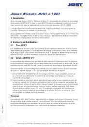
Refer to the table here to find the permitted load data for <strong>JOST</strong> fifth<br />
wheel couplings. This information is also listed in the relevant <strong>JOST</strong><br />
catalogue sheets and stamped into the type plate. The load data is<br />
applicable for proper usage pursuant to Directive 94/20 EC.<br />
If there will be additional dynamic forces, for example use on uneven<br />
road surfaces or on construction sites, do not use the complete<br />
imposed load and D value or use a stronger fifth wheel coupling or<br />
consult <strong>JOST</strong>.<br />
xx xxx xx xxxx<br />
<strong>JSK</strong> <strong>40</strong><br />
e 1<br />
1 EU approval<br />
2 Maximum D value in kN<br />
3 Maximum imposed load U in t<br />
4 Article no. and type<br />
5 Serial no.<br />
1<br />
xx xxx xx xxxx<br />
G50-X D XX U XX<br />
Every fifth wheel coupling has a serial number, which is embossed on<br />
the type plate and also underneath the type plate on the edge of the<br />
plate. This is designed to give the coupling a unique identity.<br />
xxxx<br />
4 5 <strong>JSK</strong><strong>40</strong>/07<br />
2<br />
3<br />
Permitted load data<br />
Test symbol Type Fifth wheel<br />
coupling<br />
e1 00-1245<br />
Imposed<br />
load<br />
[t]<br />
D-value<br />
[kN]<br />
30 ZDE 199 002 110 - 05/2010 <strong>JSK</strong> <strong>40</strong> & <strong>JSK</strong> <strong>42</strong><br />
<strong>JSK</strong><br />
<strong>40</strong><br />
<strong>JSK</strong> <strong>42</strong>K 20 152<br />
<strong>JSK</strong> <strong>42</strong>MK 15 126
3 Operation<br />
5<br />
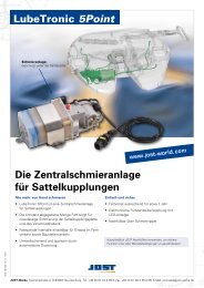
1 King pin<br />
2 Handle in forward position in driving direction<br />
3 Handle in rear position in driving direction<br />
4 Locking bar<br />
5 Lock jaw<br />
6 Coupling plate<br />
4<br />
1<br />
2<br />
6<br />
Note<br />
The following sections describe operation of the fifth wheel coupling type <strong>JSK</strong> <strong>40</strong> with the handle in the forward position in the driving direction.<br />
The operating instructions apply accordingly to the fifth wheel coupling type <strong>JSK</strong> <strong>40</strong> with the handle in the rear position.<br />
Refer to the corresponding safety information.<br />
<strong>JSK</strong> <strong>40</strong> & <strong>JSK</strong> <strong>42</strong> ZDE 199 002 110 - 05/2010 31<br />
5<br />
1<br />
4<br />
3<br />
<strong>JSK</strong><strong>40</strong>/18<br />
English
3 Operation<br />
3.1 Fifth wheel coupling closed and locked 3.2 Fifth wheel coupling ready for engagement<br />
1<br />
1 Lock jaw<br />
2 Handle<br />
3 Locking bar<br />
4 King pin<br />
4<br />
3<br />
2<br />
<strong>JSK</strong><strong>40</strong>/09<br />
1 Lock jaw<br />
2 Handle<br />
3 Locking bar<br />
4 King pin<br />
<strong>JSK</strong><strong>40</strong>/10<br />
32 ZDE 199 002 110 - 05/2010 <strong>JSK</strong> <strong>40</strong> & <strong>JSK</strong> <strong>42</strong><br />
1<br />
4<br />
3<br />
2
3 Operation<br />
3.3 To open the fifth wheel coupling 3.4 To uncouple a semi-trailer<br />
1<br />
1<br />
1<br />
b<br />
<strong>JSK</strong><strong>40</strong>/28<br />
a<br />
<strong>JSK</strong><strong>40</strong>/11<br />
<strong>JSK</strong><strong>40</strong>/12<br />
c<br />
<strong>JSK</strong><strong>40</strong>/13<br />
� Handle (1) in closed and<br />
locked position.<br />
� Pull the handle (1) until<br />
locking edge a is clear (2nd<br />
guard).<br />
� Swivel the handle (1) towards<br />
the front of the vehicle in<br />
order to release the lock b<br />
(1st guard).<br />
� Pull the handle (1) out to the<br />
end position and hook onto<br />
the edge of the plate c.<br />
� Park the vehicle on flat, firm ground.<br />
� Secure the semi-trailer to prevent its rolling away.<br />
� Extend the landing gear as described in the operating manual<br />
until the fifth wheel coupling has almost no strain on it.<br />
� Disconnect the supply lines.<br />
� Open the fifth wheel coupling (see section 3.3).<br />
� Drive the tractor unit out from under the semi-trailer.<br />
� The fifth wheel coupling is automatically ready for engagement<br />
again.<br />
3.5 To couple up a semi-trailer<br />
� Secure the semi-trailer to prevent its rolling away.<br />
� The fifth wheel coupling must be ready to engage (see section<br />
3.2). Otherwise open the fifth wheel coupling (see section 3.3).<br />
� Check the height of the semi-trailer. The skid plate must be at<br />
the same height as or preferably lower (no more than 50 mm<br />
lower) than the coupling plate on the fifth wheel coupling.<br />
� Drive the tractor unit under the semi-trailer.<br />
� The locking mechanism will close automatically.<br />
� Perform a moving-off test in a low gear.<br />
� Check the locking mechanism (see section 3.6).<br />
� Connect the supply lines.<br />
� Retract the landing gear as described in the operating manual.<br />
� Release the parking brake and remove the chocks.<br />
<strong>JSK</strong> <strong>40</strong> & <strong>JSK</strong> <strong>42</strong> ZDE 199 002 110 - 05/2010 33<br />
!<br />
Check the locking mechanism status before starting any<br />
journey (see section 3.6).<br />
English
43 Servicing Operationand<br />
testing <strong>JSK</strong> <strong>40</strong>/<strong>42</strong><br />
3.6 To check the locking mechanism<br />
1<br />
<strong>JSK</strong><strong>40</strong>/45<br />
� The indicator pin (1) on the locking edge must be within the<br />
coupling plate.<br />
1<br />
<strong>JSK</strong><strong>40</strong>/14<br />
34 ZDE 199 002 110 - 05/2010 <strong>JSK</strong> <strong>40</strong> & <strong>JSK</strong> <strong>42</strong><br />
!<br />
a<br />
<strong>JSK</strong><strong>40</strong>/15<br />
<strong>JSK</strong><strong>40</strong>/29<br />
� The locking edge a must be<br />
embedded in the coupling<br />
plate as shown.<br />
!<br />
The skid plate must rest on<br />
the fifth wheel coupling<br />
without a gap.<br />
Note<br />
To prevent the fifth wheel coupling<br />
being opened without authorisation,<br />
a security device (for example a<br />
padlock) can be inserted into the<br />
hole in the handle as shown.
4 Servicing and testing<br />
4.1 Servicing instructions<br />
The skid plate on the semi-trailer that engages with the fifth wheel<br />
coupling must meet the following conditions to provide a long service<br />
life and trouble-free function:<br />
� Max. 2 mm unevenness<br />
� Smooth and groove-free surface if possible, without weld bumps<br />
(smooth existing groove burr)<br />
� Rounded or chamfered front and side edges<br />
� Complete coverage of the fifth wheel coupling support area with<br />
an adequate reinforcement adapted to the particular application.<br />
!<br />
Effective lubrication of the top of the fifth wheel plate (apart<br />
from on the <strong>JSK</strong> with top plate liners), the lock jaw, the handle<br />
and the king pin (before using for the first time and after<br />
cleaning) is essential to ensure their long service life. In the<br />
W version, we recommend applying a thin coat of grease to<br />
the skid plate.<br />
Note<br />
When you clean the fifth wheel coupling you may produce waste that<br />
contains pollutant substances. We would like to point out that you must<br />
comply with the various national waste regulations for the disposal of<br />
this waste.<br />
4.1.1 Fifth wheel coupling with manual lubrication<br />
At short intervals, at the latest every 5,000 km:<br />
� Uncouple the semi-trailer<br />
� Clean the fifth wheel coupling and the skid plate<br />
� Lubricate the king pin, top of coupling plate (3), lock jaw (4) and<br />
locking bar (5) (see section 4.2)<br />
Every 50,000 km or every six months<br />
� Additionally lubricate the handle (1) and (2) as well as the<br />
articulated connections and guides of the levers (6) (see section<br />
4.2)<br />
The grease nipple on the edge of the coupling plate is only designed<br />
for additional greasing of the locking mechanism between service<br />
intervals. The pivot bearings of the pedestals do not need to be<br />
lubricated.<br />
4.1.2 Fifth wheel coupling with central lubrication connection<br />
(Z version)<br />
Depending on the conditions in which it is used, the grease used and<br />
metering, at the latest every 50,000 km or every six months:<br />
� Uncouple the semi-trailer<br />
� Clean the fifth wheel coupling and the skid plate<br />
� Check the function of the central lubrication system as described<br />
in the manufacturer’s instructions<br />
� Lubricate the king pin, handle (1) and (2), top of coupling plate<br />
(3), lock jaw (4), locking bar (5) as well as the articulated<br />
connections and guides of the levers (6) (see section 4.2)<br />
4.1.3 Low-maintenance fifth wheel coupling with top plate liners<br />
(W version)<br />
At the latest every 50,000 km or every six months, in harsh conditions<br />
every 25,000 km:<br />
� Uncouple the semi-trailer<br />
� Clean the skid plate and the king pin<br />
� Lubricate the king pin, handle (1) and (2), lock jaw (4), locking<br />
bar (5) as well as the articulated connections and guides of the<br />
levers (6) (see section 4.2)<br />
� Check the top plate liners for signs of wear and damage (see<br />
section 4.7)<br />
In addition, every 10,000 km grease the locking mechanism – with a<br />
trailer attached – using the grease nipple on the edge of the coupling<br />
plate.<br />
You can also install automatic lubricant dispensers. To prevent<br />
corrosion on the skid plate, we recommend that the skid plate is<br />
greased lightly during the above service intervals.<br />
4.1.4 Grease specification<br />
Extreme pressure grease (EP) with MoS2 or graphite additive, e.g.<br />
Turmogeargrease B2 supplied by Lubcon, www.lubcon.com.<br />
<strong>JSK</strong> <strong>40</strong> & <strong>JSK</strong> <strong>42</strong> ZDE 199 002 110 - 05/2010 35<br />
English
4 Servicing and testing<br />
4.2 Lubrication instructions<br />
3<br />
4<br />
5<br />
2<br />
1 Handle 3 Coupling plate 5 Locking bar<br />
2 Guide 4 Lock jaw 6 Articulated connections and guide of levers<br />
Lubricate the areas marked in yellow:<br />
� Handle (1) on side (see arrows), guide (2) as well as the articulated connections and guides of the levers (6).<br />
� Apply plenty of grease to the top (3) (except for the W version on which the top plate liners do not have to be greased).<br />
� Lubricate the lock jaw (4) and locking bar (5) with the fifth wheel coupling closed (refer to the instructions on the next page for how to close<br />
the fifth wheel coupling).<br />
Grease specification: Extreme pressure grease (EP) with MoS2 or graphite additive, e.g. Turmogeargrease B2 supplied by Lubcon,<br />
www.lubcon.com.<br />
36 ZDE 199 002 110 - 05/2010 <strong>JSK</strong> <strong>40</strong> & <strong>JSK</strong> <strong>42</strong><br />
1<br />
4<br />
5<br />
6<br />
1<br />
<strong>JSK</strong><strong>40</strong>/171
4 Servicing and testing<br />
!<br />
!<br />
1<br />
1<br />
A second person is required when closing the lock.<br />
The lock jaw (1) can be swivelled using a large flat-blade<br />
screwdriver, for example.<br />
Never swivel the lock jaw (1) by hand. Danger of crushing.<br />
1<br />
3<br />
3<br />
2<br />
<strong>JSK</strong><strong>40</strong>/166<br />
<strong>JSK</strong><strong>40</strong>/167<br />
2<br />
<strong>JSK</strong><strong>40</strong>/168<br />
� Have a second person pull<br />
the handle (2) until the lock<br />
jaw (1) is clear. Hold the<br />
handle (2) in this position.<br />
� Use a large flat-blade<br />
screwdriver, for example, to<br />
swivel the lock jaw (1)<br />
forwards until the locking bar<br />
(3) is clear.<br />
� Slowly move the handle (2)<br />
into the closed position.<br />
� Grease the lock jaw (1) and<br />
locking bar (3) on all sides.<br />
The fifth wheel coupling must be opened before the next<br />
semi-trailer is coupled up (see section 3.3).<br />
4.3 Test instructions<br />
Depending on the conditions of use, at the latest every 50,000 km or<br />
every six months, check the fifth wheel coupling, the mounting plate<br />
and/or the slider and the king pin for:<br />
� Function<br />
� Wear<br />
� Firm attachment of the fastening elements (note prescribed<br />
tightening torques)<br />
� Damage and deformation<br />
� Cracks<br />
� Corrosion<br />
� Adequate greasing<br />
� Freedom of movement of the mechanism<br />
Repair them if necessary (see the corresponding <strong>JOST</strong> repair manuals<br />
at www.jost-world.com).<br />
<strong>JSK</strong> <strong>40</strong> & <strong>JSK</strong> <strong>42</strong> ZDE 199 002 110 - 05/2010 37<br />
English
4 Servicing and testing<br />
4 Servicing and testing<br />
4.4 Wear test<br />
Fifth wheel couplings and king pins are subject to more or less wear<br />
depending on the conditions in which they are used, and this wear is<br />
noticeable by play towards the front of the vehicle.<br />
Excessive play causes shocks and may lead to instability on the road<br />
and damage to the fifth wheel coupling, mounting plate and vehicle<br />
chassis. <strong>JOST</strong> fifth wheel couplings have a manual infinite adjustment<br />
facility for the locking mechanism to extend their service lives.<br />
!<br />
The wear on the king pin must not be compensated by<br />
the adjustment facility.<br />
71-73 mm<br />
49-50,8 mm<br />
<strong>JSK</strong><strong>40</strong>/05<br />
When the wear limit on the king pin has been reached, it must be<br />
replaced.<br />
After replacing the king pin, the locking mechanism must be adjusted<br />
again.<br />
Play caused by wear on the king pin should either be accepted if within<br />
the permitted wear limit for the king pin (see illustration <strong>JSK</strong> <strong>40</strong>/05) or<br />
should be rectified by fitting a new king pin.<br />
84-82,5 mm<br />
4.5 To adjust the locking mechanism<br />
1 Lock nut<br />
2 Adjusting screw<br />
3 Lock jaw<br />
4 Handle<br />
5 Locking bar<br />
The locking mechanism must be adjusted as follows using a semitrailer<br />
without forced steering with a new king pin:<br />
� Uncouple the tractor unit on a flat, firm piece of ground.<br />
� Undo the lock nut (1).<br />
� Unscrew the adjusting screw (2) by approximately 15 turns.<br />
� Couple up the semi-trailer.<br />
� Swivel the handle (4) towards the front of the vehicle and hold it<br />
there (get somebody to assist you).<br />
� Tighten the adjusting screw (2) again until the handle (4) starts<br />
to move (have an assistant check this).<br />
� To set the recommended basic play of 0.3 mm, tighten the<br />
adjusting screw (2) by a further 1½ turns and secure it with the<br />
lock nut (1).<br />
If there is still excessive play, the wearing ring and the lock jaw must<br />
be replaced as described in the repair manual.<br />
38 ZDE 199 002 110 - 05/2010 <strong>JSK</strong> <strong>40</strong> & <strong>JSK</strong> <strong>42</strong><br />
4<br />
5<br />
3<br />
1<br />
2<br />
<strong>JSK</strong><strong>40</strong>/27
4 Servicing and testing<br />
4.6 Wear limit – locking mechanism<br />
Locking mechanism (handle forward)<br />
10<br />
0 mm<br />
0 mm<br />
0 mm<br />
0 mm<br />
<strong>JSK</strong><strong>40</strong>/99<br />
The wear limit of the lock has been reached when there is no longer any gap between the lever (10) and the coupling plate.<br />
The locking mechanism cannot be adjusted any further at this point.<br />
In this case, the wearing ring and the lock jaw must be replaced as described in the repair manual.<br />
<strong>JSK</strong> <strong>40</strong> & <strong>JSK</strong> <strong>42</strong> ZDE 199 002 110 - 05/2010 39<br />
English
4 Servicing and testing<br />
Locking mechanism (handle at the rear)<br />
0 mm<br />
16<br />
0 mm<br />
<strong>JSK</strong><strong>40</strong>/100<br />
The wear limit of the lock has been reached when there is no longer any gap between the lever (16) and the coupling plate.<br />
The locking mechanism cannot be adjusted any further at this point.<br />
In this case, the wearing ring and the lock jaw must be replaced as described in the repair manual.<br />
<strong>40</strong> ZDE 199 002 110 - 05/2010 <strong>JSK</strong> <strong>40</strong> & <strong>JSK</strong> <strong>42</strong>
4 Servicing and testing<br />
4.7 Wear limit – top plate liners<br />
2 1 2<br />
2<br />
2<br />
The top plate liners (1) and their securing bolts (2) must be checked for<br />
firm attachment, signs of wear and damage at regular intervals that<br />
depend on usage, but at least every 50,000 km or every six months.<br />
The top plate liners (1) must be replaced when they have worn to the<br />
top of the securing bolts (2).<br />
2<br />
45 Nm<br />
1<br />
<strong>JSK</strong><strong>40</strong>/06<br />
4.8 Wear limit – collars<br />
<strong>JSK</strong><strong>40</strong>/173<br />
Each of the pedestals is mounted in the fifth wheel coupling using a<br />
collar. These collars are subject to a certain amount of wear.<br />
In order to check the collars for wear, align the coupling plate by tilting<br />
it until both the “0” marks on the front and rear of the pedestal project<br />
from the coupling plate by an equal amount.<br />
Dimension “a” is reduced from the initial 5 mm to 0 mm as the wear on<br />
the collars increases.<br />
When both marks are no longer visible (a = 0 mm), this means the<br />
collars are worn and need to be renewed.<br />
<strong>JSK</strong> <strong>40</strong> & <strong>JSK</strong> <strong>42</strong> ZDE 199 002 110 - 05/2010 41<br />
”0”<br />
a<br />
English
5 Installation<br />
5.1 General installation instructions<br />
To secure the <strong>JOST</strong> fifth wheel coupling (pursuant to Directive 94/20/<br />
EC and ISO 38<strong>42</strong> / DIN 7<strong>40</strong>81) on the mounting plate or on the flitch,<br />
at least eight M16 bolts, ideally M16 x 1.5 of strength class 8.8, must<br />
be used.<br />
These must be positioned in a symmetrical pattern to the longitudinal<br />
and lateral axes of the fifth wheel coupling.<br />
If the coupling is used in harsh conditions (for example on construction<br />
sites), with trailers with forced steering or with trailers that use the full<br />
D value and/or imposed load, we recommend that you use all 12 bolts.<br />
Fifth wheel couplings with a design height of over 250 mm and a D<br />
value of over 133 kN must be secured with 12 bolts.<br />
We recommend that you use <strong>JOST</strong> mounting kits (see <strong>JOST</strong> catalogue<br />
for order numbers).<br />
The pedestals should make contact over the entire surface of the<br />
mounting plate or on the flitch as completely as possible. With<br />
undulating mounting plates, it is necessary to have a support in the<br />
middle area as well as the contact in the screw connection area (see<br />
also sections 5.2 and 5.3).<br />
We recommend securing the pedestals in the longitudinal and lateral<br />
directions and the mounting plates in the longitudinal direction by prewelded<br />
thrust plates. Use the welding methods set out by the<br />
manufacturers of the vehicle and mounting plate for this purpose.<br />
There is no need to use thrust plates, however, if it can be ensured that<br />
the correct tightening torque for the bolts and therefore the perfect<br />
friction contact can be generated and maintained at all times. The bolt<br />
connections are therefore to be designed so that the prescribed<br />
tightening torque values or prestressing forces can be applied<br />
permanently. The general rule is that the coating thickness of the<br />
paintwork around the securing area of the bolts must be no more than<br />
170 µm per component. The bolt connections are to be secured using<br />
state of the art methods to prevent them coming loose.<br />
The fifth wheel coupling must be able to move freely and must not be<br />
in contact with either the mounting plate or parts of the chassis or flitch<br />
when the vehicle is being driven.<br />
<strong>42</strong> ZDE 199 002 110 - 05/2010 <strong>JSK</strong> <strong>40</strong> & <strong>JSK</strong> <strong>42</strong>
5 Installation<br />
5.2 Installation of the fifth wheel coupling on the mounting plate<br />
1<br />
1 Fifth wheel coupling<br />
2 Flitch<br />
3 Vehicle chassis<br />
4 Mounting plate<br />
5 Thrust plates to secure the pedestals<br />
6 Thrust plates to secure the mounting plate<br />
7 Hexagonal bolt DIN EN ISO 8765/8676 (DIN 960/961) M16 x 1.5-8.8<br />
8 Washer 17 DIN 7349, 6 mm thick (min. HB150)<br />
9 Optional washer (min. HB150) or disc spring<br />
10 Hexagonal nut DIN 980 M16 x 1.5-8.8 or M20 x 1.5-8.8<br />
11 Hexagonal bolt DIN EN ISO 8765/8676 (DIN 960/961) M16 x 1.5-8.8 or M20 x 1.5-8.8<br />
12 Optional washer/disc spring<br />
Tightening torque, see section 5.4.<br />
2<br />
3<br />
4<br />
5<br />
6<br />
<strong>JSK</strong> <strong>40</strong> & <strong>JSK</strong> <strong>42</strong> ZDE 199 002 110 - 05/2010 43<br />
7<br />
8<br />
9 10<br />
11<br />
12<br />
<strong>JSK</strong><strong>40</strong>/22<br />
English
5 Installation<br />
5.3 Installation of the fifth wheel coupling on the flitch<br />
1<br />
1 Fifth wheel coupling<br />
2 Flitch<br />
3 Vehicle chassis<br />
4 Hexagonal bolt DIN EN ISO 8765/8676 (DIN 960/961)<br />
M16 x 1.5 x …-10.9 (for slot 18 x …) min. 12 pcs.<br />
M20 x 1.5 x …-10.9 (for slot 22 x …) min. 8 pcs.<br />
5 Washer 17 DIN 7349-St (min. HB250, for slot 18 x …) min. 12 pcs.<br />
Washer 21 DIN 7349-St (min. HB250, for slot 22 x …) min. 8 pcs.<br />
6 Disc spring DIN 2093<br />
A31.5 (for slot 18 x …), optionally without<br />
B<strong>40</strong> (for slot 22 x …), optionally without<br />
7 Hexagonal nut DIN EN ISO 10513 (DIN 980-V)<br />
M16 x 1.5 x 10 (for slot 18 x …) min. 12 pcs.<br />
M20 x 1.5 x 10 (for slot 22 x …) min. 8 pcs.<br />
Tightening torque, see section 5.4.<br />
2<br />
3<br />
44 ZDE 199 002 110 - 05/2010 <strong>JSK</strong> <strong>40</strong> & <strong>JSK</strong> <strong>42</strong><br />
4<br />
5<br />
6 7<br />
<strong>JSK</strong><strong>40</strong>/24
5 Installation<br />
5.4 Fastening material and tightening torque values<br />
Fastening material Strength class 8.8 Strength class 10.9<br />
Hexagonal bolt DIN EN 2<strong>40</strong>14/2<strong>40</strong>17 (DIN 931/933) standard thread M16<br />
M20<br />
Hexagonal bolt DIN EN ISO 8765/8676 (DIN 960/961) fine thread M16 x 1.5<br />
M20 x 1.5<br />
Countersunk bolt DIN 7991 M16 or M16 x 1.5<br />
M20 or M20 x 1.5<br />
210 Nm<br />
410 Nm<br />
225 Nm<br />
460 Nm<br />
170 Nm<br />
330 Nm<br />
Note<br />
The values shown above are guide values for a coefficient of friction µ tot. = 0.14. Further information is available in VDI 2230.<br />
260 Nm<br />
500 Nm<br />
280 Nm<br />
500 Nm<br />
250 Nm<br />
<strong>40</strong>0 Nm<br />
<strong>JSK</strong> <strong>40</strong> & <strong>JSK</strong> <strong>42</strong> ZDE 199 002 110 - 05/2010 45<br />
English
5 Installation<br />
5.5 To bring the handle into operating position (handle in forward position)<br />
� Undo the screw connection (1).<br />
� Swivel the handle (2) out.<br />
� Tighten the screw connection (1) again, tightening torque 46 Nm.<br />
2<br />
1<br />
46 ZDE 199 002 110 - 05/2010 <strong>JSK</strong> <strong>40</strong> & <strong>JSK</strong> <strong>42</strong><br />
1<br />
2<br />
<strong>JSK</strong><strong>40</strong>/23
5 Installation<br />
5.6 To bring the handle into operating position (handle in rear position)<br />
2<br />
� Undo the screw connection (1).<br />
� Swivel the handle (2) out.<br />
� Hook in the spring (3).<br />
� Tighten the screw connection (1) again, tightening torque 46 Nm.<br />
3<br />
1<br />
<strong>JSK</strong> <strong>40</strong> & <strong>JSK</strong> <strong>42</strong> ZDE 199 002 110 - 05/2010 47<br />
3<br />
1<br />
2<br />
<strong>JSK</strong><strong>40</strong>/25<br />
English
Siemensstraße 2, D-63263 Neu-Isenburg, Telefon +49 6102 295-0, Fax +49 6102 295-298, www.jost-world.com<br />
ZDE 199 002 110 05/2010