CIMAC Congress - Schiff & Hafen
CIMAC Congress - Schiff & Hafen
CIMAC Congress - Schiff & Hafen

Create successful ePaper yourself
Turn your PDF publications into a flip-book with our unique Google optimized e-Paper software.
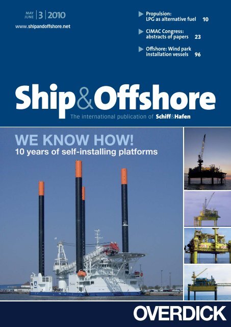
MAY<br />
JUNE | 3 | 2010<br />
www.shipandoffshore.net<br />
The international publication of<br />
� Propulsion:<br />
LPG as alternative fuel 10<br />
� <strong>CIMAC</strong> <strong>Congress</strong>:<br />
abstracts of papers 23<br />
� Off shore: Wind park<br />
installation vessels 96
����������<br />
������������������������������������<br />
�������������������������������������������������������������������������������������������������������������<br />
�������������������������������������������������������������������������������������������������<br />
��������������������������������<br />
���������������������������<br />
����� ���������� ������� �����<br />
�������������������������������<br />
�����������������������������<br />
����� ����� ���� ������ �������<br />
�������� ���������� ��������� ���<br />
��������������������������������<br />
��� �� ������ ����������� ��� ����<br />
���������������������������<br />
� � ������ � � � � � � � � � � ������ � � �<br />
�� �������� ���������� ��� �����<br />
����� ��������� ��� �����������<br />
����������� ����������� ��� ������<br />
����������� ���� ���� ���� ���� �����������������������������<br />
������������������������������ ����������������������������<br />
�������������������������������<br />
���������� �<br />
��������<br />
���������������������<br />
������������������<br />
�������������������<br />
������������������������<br />
����������<br />
��������������<br />
������������������������������<br />
�����������������<br />
��������������������������������<br />
�����������������������<br />
�����������������������<br />
���������������<br />
First Class bulk carriers: a new perspective<br />
�� � ���������� ��������<br />
Bookable days are:<br />
Tuesday, September 7th 2010<br />
Wednesday, September 8th 2010<br />
Thursday, September 9th 2010<br />
Friday, September 10th 2010<br />
SMM Daily News Advertisement<br />
The 24 th Shipbuilding, Machinery & Marine Technology International (SMM) trade fair will<br />
be staged at Hamburg Exhibition Centre from September 7 th -10 th 2010. Leading ship building<br />
companies and maritime equipment suppliers will present many innovations at this SMM.<br />
As usual, DVV Media will produce the daily trade fair newspaper SMM Daily News from<br />
Tuesday to Friday!<br />
Concept & facts you should know:<br />
SMM Daily News will be published every fair day for distribution daily to visitors<br />
and exhibitors at the SMM. At breakfast time, SMM Daily News will provide the latest<br />
news from the maritime industry to the international trade fair visitors in English.<br />
�����<br />
Here are the rates for your advertisement:<br />
183 x 251 mm<br />
1/1-page<br />
€ 4,490<br />
�������������������������������������<br />
�������������� ����������������������<br />
��<br />
�������������<br />
������������� ��<br />
������������<br />
������������<br />
����������������<br />
��������������� �������������<br />
�������������<br />
�������� �������� ��� ��� ���� ���� ����� ����� ������ ������ ������ ������ ������� ������� �������� �������� ��� ��� �� ��<br />
������������������������������<br />
������������������������������ �������������������������������<br />
�������������������������������<br />
������� ������� ��� ��� �������� �������� ����� ����� ���� ���� ����������������������������������<br />
����������������������������������<br />
�������� �������� ����� ����� ���� ���� ������ ������ ��� ��� ���� ���� ��������� ��������� ����� ����� ������ ������ ������ ������<br />
�����������������������������<br />
����������������������������� ���� ���� ��� ��� ���� ���� ��������� ��������� ������� ������� ��� ��� ��<br />
����� ����� ��� ��� ���� ���� ������ ������ ��������� ��������� �����������������������������������<br />
�����������������������������������<br />
��������������������������������<br />
�������������������������������� �����������������������������������<br />
�����������������������������������<br />
���� ���� ������ ������ ������������ ������������ ���� ���� ����� ����� ��������������������������������<br />
�������������������������������<br />
��� ��� �������� �������� ������� ������� ���� ���� ������ ����� ������� ������� ���� ���� ���� ���� ����� ����� �������� ��������<br />
�������������������������������<br />
������������������������������� ��������� ��������� ����� ����� ������� ������� ���� ���� ����� �����<br />
������ ������ ������ ������ �������� �������� ��� ��� ��� ��� ��� ��� ���������������������������������<br />
���������������������������������<br />
����������� ����������� ����� ����� ���� ���� ������� ������� ����� ��������� ���� ������ ������ ����� ����� ������ ������ ��� ���<br />
������������������������������<br />
����������������������������� ���������������������������������<br />
���������������������������������<br />
�������������������������������<br />
������������������������������� ����� ����� ����� ����� ��������� ��������� ���� ���� ����� ����� ��<br />
���������� ���������� ���� ���� �������������<br />
������������� ����������������������������������<br />
����������������������������������<br />
��������� ��������� ���� ���� ���� ���� ��� ��� �������� �������� ������������ ������������ ��� ��� ��������������<br />
�������������<br />
��������� ��������� ����������� ����������� �������� �������� ���� ����<br />
������� ������� ���������� ���������� ��� ��� �������� �������� ��������������<br />
�������������<br />
���� ���� ���������� ���������� �� �� ����������<br />
���������� �������������������<br />
�������������������<br />
����� ����� ���������� ���������� ��� ��� ������� ������� ��������������������<br />
��������������������<br />
���� ���� ��� ��� ������ ������ ��� ��� ���� ���� ����������� ���������� ��������������<br />
��������������<br />
�������������������������<br />
��������������������������<br />
�����������������������<br />
����������������������� ��������������������<br />
���������������������<br />
���������<br />
�����������<br />
183 x 125 mm<br />
1/2-page<br />
€ 2,390<br />
If you are interested in placing your advertisement in one or more issues of SMM Daily News,<br />
please contact your local representative or our office directly:<br />
Florian Visser<br />
Advertising Director<br />
Tel.: +49 – (0)40 / 237 14 –117<br />
Fax: +49 – (0)40 / 237 14 –236<br />
E-Mail: florian.visser@dvvmedia.com<br />
��<br />
���������������<br />
��������������� �����������������������<br />
�����������������������<br />
������������<br />
������������<br />
��������������������������������<br />
�������������������������������� �������������������������<br />
�������������������������<br />
���������������������������������<br />
���������������������������������<br />
������� ������� ����� ����� ����� ����� ��� ��� �������� �������� �����������������������������<br />
���� ���� �������� �������� ����������� ����������� �������� ���������<br />
������������������������������<br />
������������������������������ ��������� ��������� ��� ��� ��������� ��������� ���� ����<br />
����������������������������������<br />
��������������������������������� ��������� ��������� ���������� ���������� ���� ���� ���� ����<br />
���� ���� ������� ������� ����� ����� ����������� ����������� ���� ���� ������������� ������������� ���������� ���������� ������ ������<br />
����� ����� ���������������� ������������ ���� ����� ����� ��� ��� �����������������������������<br />
�����������������������������<br />
������ ������ ���� ���� ����� ����� ��������� ��������� ����� ���� �������������������������������<br />
�������������������������������<br />
�������������������������������<br />
������������������<br />
��������������������������������<br />
������������������������������� ����� ����� ������� ������� ���� ���� ������������<br />
������������<br />
�����������������������������<br />
����������������������������� ���� ���� ����� ����� ���������� ���������� ��� ��� �������� ��������<br />
�������������������������������<br />
�����������������������<br />
��� ��� ������� ������� ���������� ���������� ��� ��� ����� ����� ��� ���<br />
��������������������������������<br />
������������������������������� ������� ������� ����������� ����������� ���� ���� ��� ��� ���� ����<br />
������������������������������<br />
�����������������������<br />
���������� ����������<br />
����� ����� ������� ������� ������ ������ ����� ����� ������ ������ ������� ������� ���� ���� ��� ��� ��������� ��������� ������������������������������<br />
����������������������������� ����������� ��� ������� ������� ������ �������<br />
���� ���� ���� ���� ������������������������������<br />
������������������������������<br />
����������������������������������<br />
��������������������������������� ������ ������ ��������� ��������� ���� ���� ���� ���� ����� ����� �����������<br />
�����������<br />
����� ������� ����� ���� ���� �������� �������� � ��� ��� �� �� �������������������������������<br />
�������������������������������<br />
������������������������������<br />
������������������������������ ����������� ����������� �������� �������� ������� ������� ��� ���<br />
������� ��� ��� ������������ �������������<br />
��� ��� ����� ����� ��������������������������������<br />
��������������������������������<br />
����������������������������������<br />
��������������������������������� ������������������������������<br />
������������������������������ ����� ����� ���� ���� ����� ����� ����������� ����������� ����� ������� ������ ��� ��� ������� ������� � ��� ��� ��������������������������������<br />
��������������������������������<br />
������ ������ ��� ��� ����� ����� ��� ��� ���� ���� ������ ������ ����� ����� �������������������������������<br />
������������������������������� ���������� ���������� ���� ���� ���������� ���������� �� ��� �����������������������������������<br />
��������������������������<br />
���������������������������������<br />
���������������������������������<br />
����� ����� �� �� ���� ���� ������� ������� ����� ����� ����� ���� ������������������������������<br />
������������������������������ ������������������������������<br />
������������������������������ ��� ���������� ������ ��� ��� ������� �� ������ ����� ����� ��������������������������������<br />
��������������������������������<br />
�������������������������������<br />
������������������������������� �������������������������������<br />
������������������������������� ������������������������������<br />
������������������������������ �������������������������������<br />
��������������������������<br />
������������������������������<br />
������������������������������<br />
���������� ���������� �� �� ������������ ������������ ���� ���� ���� ���� ������������ ������������ ��� ��� ���������� ���������� ���������� ���������� ��� ��� ����������� ����� ������ ��� ��� �������������������������������<br />
�������������������������<br />
��������������������������������<br />
��������������������������������<br />
�������� �������� ��� ��� ����� ����� ������� ������� ����� ������ �������������� �������������� ���������� ���������� ���� ���� ����������������������������<br />
����������������������������� ������������������������������<br />
�����������������������<br />
����������������������������������<br />
����������������������������������<br />
����������������������<br />
����������������������<br />
�������������� �������������� ���� ���� ��������� ��������� ����� ����� ���������� ���������� ������ ������ ��� ��� �� ����������������������������������<br />
������������ ������������� ��������������������������������<br />
��������������������������������<br />
��������� ��������� ���������� ���������� ���� ���� ���� ���� �������������������������������<br />
������������������������������� ����������������������������������<br />
���������������������������<br />
����������������������<br />
����������������������<br />
�������������<br />
������������<br />
��������������������������������������������������������������������<br />
���� ���� ���� ���� ����� ����� ����� ����� �������� �������� ��������� ��������� ����� ����� ����� ����� ���������� ���������� ��������������������������������<br />
������������������������<br />
����� ����� ��� ��� ���� ���� ������������ ������������ ������� �������<br />
����������������������������������������������������������������<br />
�������������������<br />
������������������<br />
������� ������� �� �� ������� ������� ���� ���� ��������� ��������� ���� ���� ���������� �� �������� ��� ��� �������� �������� ��� �������� ���� ��� ��� ���� ���� �������� �������� ���� ���� �������������������������������<br />
�������������������������������<br />
���������������<br />
��������������<br />
����� ����� ������� ������� �������� �������� ���� ���� ������� ������� �����������������<br />
�����������������<br />
������������������������������<br />
�����������������������<br />
���������������������������������<br />
���������������������������������<br />
�����������������������<br />
����������������������<br />
������������������������������<br />
������������������������������<br />
������������������������������ �������� ��� ������ ����� ���� ���� ������ ����� ����� ��� ��� ��� ��� ����� ����� ������� ������� �����������������������������<br />
�����������������������������<br />
�������������������<br />
�������������������<br />
�������������������������������<br />
�����������������������������<br />
����������������������������� ������������������������������<br />
����������������������<br />
��������������������� ������� ����� ����� ������ ������ ������������<br />
������������ �������������������������������<br />
�������������������������������<br />
���������������������������<br />
��������������������������������<br />
�������������������������������� �����������������������������<br />
������������������<br />
������������������<br />
������������������������ ����������������<br />
���� ���� ��� ��� ��� ��� ����� ����� ����� ����� ���� ���� ��������� ��������� �� ��<br />
������������������������������� ����� ���� ������� ������ ��������� � ����������������������������������<br />
������������� �������������� ��������������������������<br />
��������������������������<br />
������������� ������ ��������� ��������� ������� ������ ��� ��������������������������������<br />
������������������������<br />
���� ���� ������ ������� ������� ����� ������������� ��������� ��� ������������������������������<br />
������������������������<br />
�����������������������������<br />
�������������������������������<br />
������ ������ ���� ���������� �� �����������<br />
�������������������������������<br />
�����������������������<br />
��������������������������������<br />
����������������������������������<br />
�������������������������������� ������ ������ ����� ��� ���� ������ �������������������������������<br />
������������ ������������ ��������� ���������<br />
�������������������<br />
������� ���� ���� ���� ����� ��� �����������������������������<br />
����������������������<br />
����������������������������� ���������������������������������<br />
�������������������������<br />
��<br />
����������������<br />
�����������������<br />
��������������������������������� ������������������������������� �������������������� ����������<br />
������������������������������� ����� ����� �������� ����� ����� ���������������������������������<br />
�������������������������<br />
���������������<br />
�����������������<br />
����� ���� ��������������� ������� ������������������������������ �������������������������������<br />
����������������������<br />
����������������� ����������������� �������������<br />
�������������<br />
��� �������� ��� ��� �������� ��� �� ������������ ��� ���� ���� ��� �����������������������������<br />
����������������������<br />
����������������� ����������������� ������������<br />
������������<br />
���������������� ���������������� ������ ������<br />
������ ����� ���� ���� ���� ��� ��� ������������������������������� �������������������������������<br />
����������������������<br />
������������������� ������������������� ��������� ���������<br />
����������� ������� ���� ��� ������� ����� �������� ���� ���� ���������� ������������������������������<br />
�����������������������<br />
���������������� ���������������� ������� �������<br />
������������������������������� �������� ��� �� ������� ������ �������������������������������<br />
������������������������<br />
�������������� �������������� ����������������<br />
����������������<br />
�������������������������������� ���������������� ��������� �������� ��������������������������������<br />
��������������������������<br />
��������������������� ��������������������� �������� ��������<br />
��������������������������������� �������������� ����������� ��� ��������������������������������<br />
����������������������<br />
�������������������� �������������������� ����� �����<br />
������ ������ ������� ������� �<br />
��������������������������������� ������������������������� ���������������������������������<br />
���������������������������<br />
��� �� ����������������������������������������� �������������� � ����������������� � ����<br />
������������������������������������������ �������������� � ����������������� � ���� �� ��<br />
183 x 83 mm<br />
1/3-page<br />
€ 1,650<br />
In association with<br />
YOUR logo<br />
183 x 63 mm<br />
1/4-page<br />
€ 1,240<br />
����������������������<br />
����������������������<br />
����������������������������<br />
����������������������������<br />
���� ���� ���������� ���������� ���������� ���������� �� �� ���������������������������������<br />
���������������������������������<br />
������� ������� ���������� ���������� ����� ����� ������ ������ �������������������������������<br />
�������������������������������<br />
������ ������ ���� ���� �������� �������� ���� ���� ������ ������ �������������������������������<br />
�������������������������������<br />
����� ����� �������� �������� ���� ���� ���� ���� ���� ���� �����������������������������<br />
�����������������������������<br />
�������� �������� ���� ���� ���� ���� ��������� ��������� ���� ���� ��������������������������<br />
��������������������������<br />
�����������������������������<br />
����������������������������� ���� ���� ������� ������� �����������<br />
�����������<br />
����������������������<br />
����������������������<br />
�����������������������������<br />
�����������������������������<br />
���������������������������������������������������������������<br />
��������������������������������������������������������������<br />
���� ���� ������������ ������������ ����� ����� ���� ����<br />
�������������������������<br />
�������������������������<br />
���� ���� ������ ������ ������ ������ ��� ��� ���� ���� ������ ������ ��� �� ����������� ����������� ����������� ����������� ���� ����<br />
��� ��� �������� �������� ������� ������� ����� ����� ������ ������ �������������������������������<br />
�������������������������������<br />
�������������������������<br />
������������������������� ����� ����� �������� �������� ���� ���� ������ ������ ����� ����� ����� ����� �������� �������� ����������� ����������� ��� ���<br />
������������������������������<br />
������������������������������ ����� ����� �������� �������� ��� ��� �� �� ����������� �����������<br />
��������� ��������� ��������� ��������� ��� ��� ������� ������� ���� ���� ������ ������ ��� ��� ������� ������� ���� ���� ���� ���� ��� ��� ��������� ��������� ����� ����� ���� ���� �������� �������� �������� �������� ��� ��� ��� ��� �������� �������� ���� ���� ��� ���<br />
�������������������������������<br />
������������������������������� ���� ���� ����� ����� ������� ������� ������� ������� ����� ����� ��������� ��������� ��� ��� ������ ������ ��� ��� ����� ����� ���� ���� ����������� ����������� ������������ ������������ ���� ����<br />
������� ������� ��� ��� ������ ������ ���� ���� �������� �������� ���������������� ���������������� ������������<br />
������������ ���� ���� ������� ������� ����� ����� �������� �������� ����� ����� �����������������������������<br />
�����������������������������<br />
����������� ����������� ������� ������� �������� �������� ���� ���� �������� �������� ������� ������� ��������� ��������� ���� ���� ���������������������������������<br />
��������������������������������� ������������������������������<br />
������������������������������<br />
�������������������������������<br />
������������������������������� ������������ ������������ ����� ����� ������ ������ ������� ������� �������������������������������<br />
������������������������������� ������������������������������<br />
������������������������������<br />
�������������������������������<br />
������������������������������� ���������� ���������� ����� ����� �������� �������� ������� ������� ������������������������������<br />
����������������������������� ������������������������������<br />
������������������������������<br />
����������������������������<br />
���������������������������� ����� ����� ���� ���� ���� ���� ��������� ��������� ���� ���� ������������������������������<br />
������������������������������ �����������������������������<br />
�����������������������������<br />
���������������������������������<br />
��������������������������������� ���������������������������������<br />
��������������������������������� ����� ����� ���������� ���������� ��� ��� ���������� ���������� ��� ��� ���� ���� ���������� ���������� ����� ����� ������� �������<br />
����������������������������<br />
���������������������������� �����������������������������<br />
����������������������������� ���� ���� ������� ������� ����� ����� ��� ��� �� �� ����� ����� ����� ������ �� �� ������������� ������������� ��� ��� ���� ���� ���� ���� ��� ���<br />
�������������������������<br />
������������������������� ����� ����� ��������� ��������� ������ ������ ���� ���� �� �� ���������� ���������� ��� ��� ���������� ���������� ���� ���� ��������������������������<br />
��������������������������<br />
����������������������������<br />
���������������������������� ��������������������������������<br />
�������������������������������� ������������������������������<br />
������������������������������<br />
��� ��� ���� ���� ����� ����� ���� ���� ������� ������� ���� ���� �������������������������������<br />
������������������������������� ������� ������� ������ ������ �� �� ��������� ��������� ����� ����� ��� ��� ���� ���� ���������� ���������� ������� ������� ���� ����<br />
�� ��������� ��������� ������������ ������������ ��� ��� ���������� ����������<br />
��� ��� �������� �������� ��� ��� ������ ������ ����� ����� �����������������������������<br />
�����������������������������<br />
������������������������������<br />
������������������������������ ��������� ��������� ��������� ��������� ������ ������ �� �� ������ ������ ������������ ������������ ���������� ���������� ���� ���� ��� ��� ������������������������������<br />
������������������������������<br />
�������� �������� ��� ��� �� �� ��������� ��������� ��� ��� ����� ����� ������� ������� ��� ��� ����������� ����������� ���� ���� ����� ����� ��������������������������������<br />
�������������������������������� �������� �������� ������� ������� ����� ����� �������� ��������<br />
�������� �������� ����������� ����������� ���� ���� ���� ���� ������� ������� ����� ����� �������� �������� ������� ������� ���� ���� ����������� ����������� ���� ���� �������� �������� ������ ������ ��� ��� ������� ������� ����� ����� �� �� ���� ���� �������� ��������<br />
������������ ������������ ���������� ���������� ���� ���� ������������������������������������<br />
������������������������������������ �����������������������<br />
����������������������� ����������������������������<br />
����������������������������<br />
����� ����� �������� �������� ��������� ��������� ��� ��� ������� ������� ���� ���� ������ ������ ��������� ��������� ��� ��� ����� ����� ������ ������ ������������ ������������ ������ ������ �����������������������������<br />
�����������������������������<br />
������������������������������<br />
������������������������������ ������������������������������������<br />
������������������������������������ ���� ���� ��������� ��������� ����������� ����������� ������ ������ ������������������������������<br />
������������������������������<br />
������������������������������<br />
������������������������������ ����������������������������������<br />
���������������������������������� ������������� ������������� ��� ��� ������������ ������������ ���� ���� ����� ����� ����� ����� ���� ���� ����� ����� �������� ��������<br />
������ ������ ����������� ����������� ������� ������� ���� ���� ������������������������<br />
������������������������ ���� ���� �������� �������� ������� ������� �������� �������� ����� ����� ���� ���� ��������� ��������� ����������� ����������� ����� ����� ��� ���<br />
�����������������������������<br />
�����������������������������<br />
���� ���� ����� ����� ������������ ������������ ����� ����� ��� ��� ������ ������ ��� ��� �� �� ���������� ���������� ������ ������<br />
������������������������������<br />
������������������������������ �������������������������������<br />
������������������������������ ��������������������������������<br />
�������������������������������� ����������������<br />
����������������<br />
��������� ��������� ���� ���� �������������<br />
������������� ��������������������������������<br />
�������������������������������� ���� ���� ���������� ���������� ��������� ��������� ������� �������<br />
���� ���� ������� ������� ��������� ��������� �������� �������� ����������������������������<br />
��������������������������� ���� ���� ���� ���� ������ ������ ���������� ���������� ���� ���� ����������������������<br />
����������������������<br />
��������������<br />
��������������<br />
�����������������������������<br />
����������������������������� �������������������������������<br />
������������������������������� ���������<br />
���������<br />
WIN<br />
A SAILOR 500 0 FleetBroadband FleetB<br />
terminal<br />
plus plus a crew communication communic solution and<br />
mobile internet internet et bundle bundle<br />
Visit the Inmarsat stand, hall B6, stand sta tand 111 and complete a<br />
competition entry entry form.<br />
Terms and conditions apply.<br />
The mobile satellite company TM<br />
The mobile satellite company TM<br />
�� � �������������� �������������� �� ����������������� ����������������� �� ���� ����<br />
������������������������������������������ ������������������������������������������ ��<br />
������������������������������������������������������<br />
� ����������������������������������������������<br />
�����������������������������������������������<br />
����������������������������������������������������������������������������
Leon Schulz M.Sc.<br />
Managing Editor<br />
Malta<br />
leon.schulz@dvvmedia.com<br />
This year´s 26th <strong>CIMAC</strong> <strong>Congress</strong> in Bergen, Norway, on<br />
June 14th-17th is the most important international meeting<br />
for the internal combustion engine industry.<br />
Ship&Offshore is honoured to be the only publication to<br />
offer the abstracts of the congress papers to its readers. These<br />
are impressive in terms of quantity and in particular are of<br />
excellent quality showing a very high level of competence.<br />
The papers clearly indicate that makers of engines and<br />
components are focusing their R&D efforts on reducing<br />
emissions. Given the further tightening of exhaust emission<br />
limits, the development of new or alternative environmentfriendly<br />
propulsion technologies and suitable exhaust gas<br />
treatment concepts is becoming increasingly signifi cant in<br />
shipbuilding.<br />
This is especially important with respect to the introduction<br />
of the IMO-TIER 3 limits valid for the emission control<br />
areas in 2016. These require a reduction in nitrogen oxide<br />
emissions of approx. 80% compared with current values.<br />
Particularly in view of new regulations for sulphur content<br />
in fuel or for sulphur oxide emissions, new technological<br />
approaches are required for marine diesel engine plants.<br />
Technical solutions based on exhaust gas treatment such<br />
as SCR catalysts or sulphur scrubbers as well as dual-fuel<br />
or exhaust gas recirculation concepts are currently being<br />
discussed. Several concepts are expected to be available in<br />
2016.<br />
For providing a reliable and effi cient propulsion system as<br />
well as onboard power generation, the marine diesel engine<br />
has not yet reached its development limits and has substantial<br />
potential for meeting the stringent emission regulations<br />
of the future as well as becoming even more effi cient.<br />
An interesting development for further reducing emissions<br />
is presented in an article describing the use of LPG as an<br />
alternative fuel (see page 10). With the new gas code, the use<br />
Dr.-Ing. Silke Sadowski<br />
Editor in Chief<br />
Hamburg<br />
silke.sadowski@dvvmedia.com<br />
Combustion engines<br />
for the future<br />
COMMENT<br />
of LPG (propane and butane) as a fuel for ship propulsion<br />
has thus come a step closer to marketability.<br />
In addition to emission levels, operational costs are playing<br />
a signifi cant role for the shipping industry, especially with<br />
charter rates remaining low. Lubrication is an important factor<br />
in saving costs. A fl exible way of adjusting and optimising<br />
cylinder oil consumption for two-stroke diesel engines is<br />
presented on page 12.<br />
Another important congress in the near future will be the<br />
29th International Conference on Ocean, Offshore and Arctic<br />
Engineering (OMAE 2010) in Shanghai on June 6th-11th.<br />
The organisers of this event, which has top speakers and is<br />
expected to attract 850 participants, have in addition to the<br />
traditional focal areas of offshore and ocean research technology<br />
put high priority on offshore wind energy, in line<br />
with the enormous current and future global signifi cance of<br />
this area. It is forecast that by 2013 there will already be offshore<br />
wind farms worldwide with an overall output of well<br />
over 11 GW (Gigawatt), some located in water depths of<br />
over 40m at great distances from the mainland. The installation<br />
and operation of such wind farms require extremely<br />
high technological expertise and sophisticated logistics,<br />
necessitating close cooperation between operators, offshore<br />
service providers and wind power plant makers.<br />
Larger and more powerful Jack-Up Platforms are needed in<br />
order to be able to work safely and effi ciently, even in very<br />
deep water, and meet more stringent requirements for the<br />
construction of offshore wind farms. Innovative and ever<br />
larger wind turbine installation units are necessary. Two of<br />
the world’s largest are described on page 96 and 98.<br />
Ship & Offshore | 2010 | N o 3 3
� Shipbuilding &<br />
Equipment<br />
Propulsion &<br />
manoeuvring technology<br />
10 Dual-fuel engine using LPG<br />
12 Optimizing cylinder oil<br />
consumption<br />
13 Cutting diesel engine<br />
emissions<br />
14 The world’s largest solar<br />
powered ship<br />
14 MOL develops diesel<br />
particulate fi lter<br />
15 Nozzles specifi c to performance<br />
requirements<br />
15 Promas Lite for Carnival Glory<br />
16 Norwegian Epic powered by<br />
innovative propulsion system<br />
Euro 17,50 | www.schiffundhafen.de<br />
62. Jahrgang | C 6091<br />
01|10<br />
4 Ship & Offshore | 2010 | N o 3<br />
��Maritime Wirtschaft:<br />
Jahresbilanz und Ausblick 12<br />
��<strong>Schiff</strong>sbetrieb: Condition-<br />
Based Maintenance 24<br />
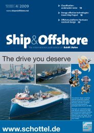
The Wake<br />
– the only emission we want to leave behind<br />
��SO X -Emissionen: Trockenes<br />
Abgasbehandlungssystem 38<br />
NO 3 INSIDE REPORT<br />
18 JANUARY<br />
2010 German yard Lloyd Werft is in talks about the entry of a new strategic investor into the company.<br />
| “We are in talks about the sale of a shareholding,” said yard chief executive Mr Werner Lüken, declining<br />
to name the possible buyer. The new investor could buy shareholdings in the yard currently<br />
owned by Italian yard Fincantieri and the yard’s management, he said. He declined to name the<br />
potential buyer. Fincantieri bought a 21 percent share in the yard in 2006 but had now given up<br />
plans to buy a majority stake and develop strategic cooperation in cruise ship modernisation, a sector<br />
both yards specialise in. The Bremen state government was also interested in selling its 13.1 percent<br />
shareholding in the yard, a state spokesman said. Managers control the rest of the shares. (See also<br />
Germany)<br />
German engineering group ThyssenKrupp is in fi nal talks on the sale of its Hamburg yard Blohm<br />
+ Voss to United Arab Emirates (UAE) buyer Abu Dhabi Mar, according to informed sources. |<br />
The two parties aim that ThyssenKrupp’s supervisory board approve the deal by end-January, the<br />
sources said. The purchase price has not been agreed yet, but insiders suggest a sum in the lower<br />
three-digit million euro range. Apart from that, Abu Dhabi Mar wants to win corvette and yacht orders.<br />
ThyssenKrupp said only that talks are continuing.<br />
Shipbuilder STX has confi rmed that some 430 jobs may be cut at its Turku shipyard in Finland. |<br />
The company adds that nearly all staff can expect working hours to be cut or compulsory holidays to<br />
be introduced at some point because of a lack of orders. Around 370 of the job cuts affect shipyard<br />
workers; another 60 offi ce jobs are to be slashed. The shipyard’s current ship order, the luxury liner<br />
Allure of the Seas, is well on its way to completion. The future of the shipyard seems rather bleak if<br />
new orders do not surface. The company launched layoff talks in early November of last year. Talks<br />
with staffs are still continuing. Some of the layoffs will be carried out this winter. The rest are expected<br />
to occur by the end of the year.<br />
South Korean shipbuilders won fewer newbuilding orders than their Chinese rivals in 2009 and<br />
China’s shipbuilding order book is now larger than Korea’s, London-based market researcher<br />
Clarkson Plc said. | Korean shipbuilders won a combined 3.15 million compensated gross tons<br />
(CGTs) in new orders last year, accounting for 40.1 percent of all new global orders, said Clarkson.<br />
New orders at Chinese shipyards totalled 3.49 million CGTs during the cited period, accounting for<br />
a dominant share of the total new world orders, Clarkson said. Market observers said Chinese shipbuilders<br />
have won new orders for cheaper, simple vessels, while South Korean shipbuilders have<br />
continued to focus on high-priced vessels and offshore oilfi eld facilities. South Korea also gave up the<br />
top position to China in the global shipbuilding industry in terms of order backlogs, according to the<br />
researcher. South Korean shipbuilders’ combined order backlogs totalled 52.83 million CGTs as of<br />
early January 2010, compared with Chinese rivals’ 53.22 million CGTs, it said.<br />
Indian shipbuilders are heading for another hard year in 2010 amidst weak demand and prospects<br />
of order cancellations as the global economy struggles to emerge from a slowdown, analysts<br />
said. | Bharati Shipyard remains a lone promising outlook for investors on expectation its recent<br />
acquisition of customer Great Offshore Ltd, an Indian offshore contractor. The takeover of Great<br />
Offshore will boost Bharati’s order book and cash fl ows as Great Offshore has major expansion plans.<br />
The Indian shipbuilding sector faced a tough 2009 as new orders collapsed. “For 2010, we do not<br />
see improved orders. The order book has been stagnant and will continue to remain so,” said Kunal<br />
Lakhan, a shipbuilding analyst at Indian analyst KR Choksey. While Lakhan expects some shipping<br />
fi rms to delay delivery to next year, others are concerned that the over-supply may lead to order cancellations<br />
for shipyards (See also India)<br />
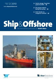
<strong>CIMAC</strong> <strong>Congress</strong><br />
The <strong>CIMAC</strong> <strong>Congress</strong>, which takes place every<br />
three years, will be held in Bergen, Norway, this<br />
time. It is devoted to the presentation of papers<br />
on engine production covering state-of-the-art<br />
technologies and applications. The number of<br />
abstracts submitted for selection is 295, which is<br />
an all-time high. 182 papers have been accepted<br />
for regular sessions and 66 for the poster session.<br />
<strong>CIMAC</strong> has a reputation for being a lively and<br />
attractive forum and is the main platform for<br />
dialogue between the engine industry’s technical<br />
experts and its customers.<br />
���������<br />
�������� | ��| ����<br />
www.shipandoffshore.net<br />
The international publication of<br />
�����������������<br />
� ���������������� 10<br />
��� ����� ��� �������<br />
��������������������������������<br />
� ������������������ 18<br />
�������������������������������<br />
���������������� 32<br />
��� ������� ����� ���������<br />
������� ���������� ��������<br />
����������� ��� ���������<br />
�������� ��� ���� ��������<br />
������������ ����������<br />
�������� ����� �� �� �� �� ���<br />
������� ��� ��������� �����<br />
��� ������� ������� �� �����<br />
���������� ��� �������� ���������<br />
��� ������� �� � ���� ����� ��<br />
„CSAV RIO MAIPO“ S. 3<br />
TANKER WIEDER FREI<br />
Reederei M. Lauterjung bringt ihren<br />
ersten Autofrachter-Neubau in Fahrt Der mit 28 Besatzungsmitgliedern<br />
gekaperte griechische Tanker „Maran<br />
FRACHTABSCHLÜSSE S. 14 Centaurus“ ist seit gestern wieder<br />
VLCC „Crude Star“ tritt Jahrescharter<br />
frei. Zuvor sollen sich an Bord dramatische<br />
Szenen abgespielt haben:<br />
bei Clearlake zu 32 000 Dollar/Tag an<br />
Nach dem Abwurf eines Lösegeldes<br />
in unbekannter Höhe nahmen sich<br />
SHIPINX S. 16<br />
rivalisierende Piratenbanden gegen-<br />
Der Indikator für die Seeverkehrsseitig<br />
unter Beschuss. Seite 13<br />
wirtschaft fi el auf 330,43 Punkte<br />
Dienstag, 19. Januar 2010 C 6612 | 63. Jahrgang Nr. 12 www.thb.info<br />
DFDS LISCO verlässt Lübecker <strong>Hafen</strong><br />
Die seit 2003 betriebene RoPax-Linie „Hansa Bridge“ von Lübeck nach Riga wird zum Monatsende eingestellt<br />
Das Jahr 2010 beginnt für<br />
der Dienst von vier auf zwei<br />
den Lübecker <strong>Hafen</strong> mit ei-<br />
Abfahrten pro Woche redunem<br />
Rückschlag. Die Reeziert<br />
worden. Zum Jahresderei<br />
DFDS LISCO verlässt<br />
wechsel entschied sich die<br />
die Hansestadt.<br />
Reedereizentrale in Kopenhagen<br />
dann für die Einstel-<br />
Die Linie „Hansa Bridge“<br />
lung der kompletten Linie,<br />
zwischen Lübeck und Riga<br />
die 2003 mit der Verlagerung<br />
wird eingestellt, teilte das<br />
von Kiel nach Lübeck gestar-<br />
Unternehmen jetzt in Kotet<br />
war. Die bislang zwischen<br />
penhagen mit. Die Fracht-<br />
Lübeck und Riga eingesetzfähre<br />
„Kaunas“ soll am 27.<br />
te „Kaunas“ wird zukünftig<br />
Januar ihre letzte Reise von<br />
als Ersatzschiff auf anderen<br />
der Trave nach Riga antre-<br />
DFDS-Linien verkehren.<br />
ten. Die Reedereiagentur<br />
Die „Hansa Bridge“ war eine<br />
in Lübeck mit sieben Mit-<br />
von zwei Lettland-Linien des<br />
arbeitern wird danach ge-<br />
Lübecker <strong>Hafen</strong>s. Die lettischlossen.<br />
Nach der Ein- Die Fähre „Kaunas“ wird zukünftig als Ersatzschiff auf anderen DFDS-Linien verkehren sche Reederei AVE ist aber<br />
stellung dieses Dienstes sol-<br />
auch von der Krise betroflen<br />
die anderen DFDS-Lini- Sassnitz – Klaipeda. Stärkste RoPax-Fähren „LISCO Glo- zwei Abfahrten. Die „Hansa fen. Ihre Fähre „AVE Liepaen<br />
nach Osteuropa gestärkt Verbindung mit weit über eiria“ und „LISCO Maxima“ Bridge“ hatte mit Beginn der ja“ hat den Fahrplan Ende<br />
werden. DFDS unterhält von ner Million Tonnen Ladung verkehren. Auf der bisher Wirtschaftskrise im Herbst 2009 vorübergehend einge-<br />
Deutschland aus drei Routen und 65 000 Passagieren pro mit einer Abfahrt pro Woche 2008 erhebliche Rückgänstellt und wartet gegenwär-<br />
ins Baltikum: Kiel – Klaipe- Jahr ist die Route Kiel – Klai- bedienten Route Sassnitz – ge bei der Ladung verzeichtig in Gdansk auf eine Besseda,<br />
Kiel – St. Petersburg und peda, auf der die modernen Klaipeda gibt es zukünftig nen müssen. Zunächst war rung der Lage. FB/ed<br />
„Zusage von höchster Ebene“<br />
Niedersachsen sieht Y-Trasse nicht gefährdet<br />
150 Capesize-<strong>Schiff</strong>e warten<br />
in Lade- und Löschhäfen<br />
Trotz angeblicher Streiverfahren werde vorbereitet.<br />
chungspläne der Deutschen Mehrere Zeitungen berichte-<br />
2010 stark erhöhte Erz- und Kohleimporte nach China erwartet<br />
Bahn sieht das Land Niederten unter Berufung auf ein insachsen<br />
den Bau der Y-Trasternes Bahnpapier, dass we- Der Capesize-Markt war Seiten und einigen Analysten liefert werden. Angekündigt<br />
se nicht gefährdet. Für den gen der staatlichen Finanz- in den ersten drei Wochen von zehn Prozent (Angebot) waren im Januar 2009 etwa<br />
Bau der milliardenteuren not wichtige Schienenprojek- des Dezembers rückläufi g. bis 40 Prozent (Forderung) 170 Einheiten. Weitere 300<br />
Schnellstrecke von Hannote auf dem Prüfstand stehen,<br />
Preiserhöhungen die Rede bis 350 Capesize-Neubauver<br />
Richtung Hamburg und darunter auch in Niedersach- Der Timecharter-Durch- war. 2010 werden stark erten sind für dieses Jahr re-<br />
Bremen gebe es die Zusage sen. Ein Bahnsprecher sagte, schnitt fi el auf 38 000 US- höhte Erz- und Kohleimporgistriert. von höchster politischer Ebe- es gebe keine Streichliste bei Dollar pro Tag. In der letzte nach China erwartet. ILS (International Logisne,<br />
sagte ein Sprecher des der Bahn. Man sehe vielmehr ten Woche des Jahres erholte Die weltweite Stahlproduktic Services) Chartering ist<br />
Verkehrsministeriums ges- einen großen Investitionsbe- sich der Markt und beendete tion verlief im vergangenen ein unabhängiger <strong>Schiff</strong>stern<br />
in Hannover. Das Plandarf beim Schienennetz. ev/jm das Jahr bei 42 000 US-Dol- Jahr sehr viel besser als ermakler mit Sitz in Hamburg<br />
lar pro Tag, teilte der <strong>Schiff</strong>s- wartet. Im Vergleich zu 2008 und spezialisiert auf inter-<br />
Foto: Behling<br />
������������ ����������� ��������<br />
����� ��������� ��������<br />
����������<br />
������������������<br />
��������� � ���������� � �����������<br />
as from page 23<br />
International Publications for Shipping, Marine and Off shore Technology<br />
Free issues<br />
available!<br />
Just send us an email:<br />
service@dvvmedia.com<br />
18<br />
Find out more at<br />
www.shipandoff shore.net<br />
or www.thb.info
� Shipbuilding &<br />
Equipment<br />
Ship’s paint & surface<br />
coating technology<br />
18 ”Multiple benefi ts” of biocidefree<br />
underwater hull protection<br />
19 Tie-coat Nexus X-Trend could<br />
save drydocking charges<br />
Industry news<br />
20 Basic Approval to ballast<br />
water management system<br />
21 Fall-pipe and rock-dumping<br />
vessel launched<br />
An advertising supplement of the DVV<br />
Media Group is enclosed to a part of the<br />
copies of this Ship & Offshore issue<br />
96<br />
� Offshore &<br />
Marine Technology<br />
Offshore windenergy<br />
96 Thor follows Odin as steel<br />
leviathan<br />
98 A titan of wind turbine<br />
installation units<br />
99 Call for EU investment<br />
99 Renewable energy<br />
New Building<br />
100 Offshore Support Vessels<br />
from Poland<br />
� Regulars<br />
COMMENT ...........................3<br />
NEWS & FACTS ...................6<br />
BUYER‘S GUIDE ...............107<br />
INDEX OF ADVERTISERS 123<br />
IMPRINT ........................... 123<br />
CONTENT | MAY/JUNE 2010<br />
Trends<br />
104 Shipping confi dence hits<br />
fi fteen-month high<br />
118<br />
� Ship &<br />
Port Operation<br />
Classifi cation<br />
105 Pilot scheme for extended<br />
drydocking<br />
Security<br />
106 Propeller Arresters to stop<br />
pirates<br />
Navigation &<br />
communications<br />
118 Intelligent integrated<br />
bridge system<br />
120 Enhanced target detection<br />
ABB Turbocharging.<br />
Setting a new<br />
standard. ABB Turbocharging introduces the all-new<br />
A100 turbocharger generation as a significant<br />
step in the development of single-stage, highefficiency,<br />
high-pressure turbocharging.<br />
www.abb.com/turbocharging<br />
Ship & Offshore | 2010 | No Ship & Offshore | 2010 | N 3 5<br />
o 3 5
INDUSTRY | NEWS & FACTS<br />
Powerful AHTS with a bollard pull of 287 t: Normand Ranger<br />
Normand Ranger delivered<br />
Ulstein Verft | AHTS Normand Ranger for Solstad<br />
Offshore ASA was recently delivered from Ulstein<br />
Verft AS, Ulsteinvik.<br />
Ulstein Verft had won the contract with GIEK<br />
and Sparebank 1 SR-Bank for completion of the<br />
anchor handling vessel last spring. The ship came<br />
to Ulstein Verft from the bankrupt shipyard Karmsund<br />
Maritime Service in August 2009.<br />
91 m long and 22 m wide Normand Ranger is an<br />
Anchor Handling Tug Supply Vessel of type VS 490<br />
designed by Vik Sandvik. The bollard pull amounts<br />
to 287 tonnes. Normand Ranger was built according<br />
OTC: High<br />
attendance<br />
Offshore Technology Conference<br />
| Attendance at the 2010<br />
Offshore Technology Conference<br />
(OTC) reached 72,900<br />
when offshore energy industry<br />
experts from around the world<br />
came together to share technological<br />
advances and innovative<br />
approaches at the world’s largest<br />
event for offshore resources<br />
development. The OTC 2010<br />
was held on May 3-6 at Reliant<br />
Park in Houston, USA. The<br />
sold-out exhibition is said to<br />
be the largest in 28 years, totalling<br />
more than 52,760 square<br />
metres. In order to increase the<br />
necessary size, OTC expanded<br />
the exhibition area to also include<br />
the Reliant Arena in addition<br />
to the Reliant Center.<br />
Covering four full days, this<br />
year’s technical program offered<br />
sessions on renewable<br />
energy sources including offshore<br />
wind and wave energy.<br />
6 Ship & Offshore | 2010 | N o 3<br />
OTC’s Spotlight on New Technology<br />
Program highlighted<br />
13 innovative technologies,<br />
which are already making the<br />
industry more effective.<br />
OTC continues to grow with<br />
two new conferences. The OTC<br />
Brazil conference is scheduled<br />
for 4-6 October 2011 in Rio<br />
de Janeiro. OTC’s fi rst Arctic<br />
Techno logy Conference will<br />
take place 7-9 February 2011<br />
in Houston, as a separate new<br />
conference focusing on both<br />
offshore and onshore technology<br />
for Arctic exploration and<br />
development.<br />
The 2011 OTC takes place 2-5<br />
May at Reliant Park.<br />
to DNV class Clean design. Also, catalytic reactors<br />
for minimum NO X emissions are installed and a<br />
Green Passport complying with IMO ship recycling<br />
scheme is issued. The 4,019 dwt new building<br />
is propelled by two large main diesel engines of<br />
8,000 kW each at 850 rpm reaching a max speed of<br />
18.5 kts. Main deck area measures 760 m² and it is<br />
equipped with two knuckle boom shipboard/harbour<br />
cranes and a multi deck handler. The AHTS<br />
was built with a hotel compliment with permanent<br />
capacity for 58 persons. Low noise and vibration<br />
levels are recorded in the accommodation.<br />
Approval for Cape Wind project<br />
Offshore windpark | The fi rst<br />
offshore wind farm in the USA<br />
recently got approval of the<br />
U.S. Department of the Interior.<br />
The project is to be constructed<br />
on Horseshoe Shoal<br />
in Nantucket Sound off the<br />
coast of Massachusetts.<br />
Looking ahead, the president<br />
of Cape Wind’s developer<br />
Energy Management Inc. Jim<br />
Gordon said, “We hope to begin<br />
construction of Cape Wind<br />
before the end of the year.”<br />
Once the project gets underway,<br />
construction is estimated<br />
to take two years.<br />
In 2009 Cape Wind had<br />
completed its State and Local<br />
permitting process with a<br />
unanimous vote of the Massachusetts<br />
Energy Facilities Siting<br />
Board to grant Cape Wind<br />
a ‘Certifi cate of Environmental<br />
Impact and Public Interest’<br />
that rolls up all State and Local<br />
permits and approvals into<br />
one ‘composite certifi cate’.<br />
FSV to NOAA<br />
Fincantieri | The NOAA (National<br />
Oceanic and Atmospheric Administration)<br />
has contracted a<br />
Fisheries Survey Vessel (FSV) with<br />
Italy based Fincantieri’s American<br />
subsidiary Marinette Marine Corporation<br />
(MMC). The research<br />
vessel is funded under the American<br />
Recovery and Reinvestment<br />
Act to be delivered in 2013 to the<br />
ship’s homebase in San Diego.<br />
The ship will serve the Southwest<br />
Fisheries Science Center (SWFSC)<br />
replacing the David Starr Jordan.<br />
63.5m long and 15.2m wide, the<br />
vessel will be equipped with a<br />
full suite of modern instrumentation<br />
for sampling and advanced<br />
navigation systems with multifrequency<br />
acoustic sensors and<br />
extensive laboratories. The vessel<br />
will be able to carry out surveys<br />
on marine fauna, including<br />
mammals, turtles and fi sh and<br />
conduct studies into the effects<br />
of climate change on the ecosystems<br />
off the west coast of North<br />
America and in the eastern tropical<br />
Pacifi c Ocean.<br />
130 wind turbines will produce<br />
up to 420 megawatts of<br />
clean, renewable energy.<br />
A meteorological tower at the<br />
Horseshoe Shoal has gathered<br />
wind, weather, and ocean<br />
data for more than three years<br />
Cape Wind has entered into<br />
an agreement with Siemens to<br />
supply its 3.6-MW turbines for<br />
the offshore wind farm and, at<br />
the same time, Siemens also<br />
announced plans to open a<br />
U.S. Offshore Wind offi ce in<br />
Boston.
Gone into service: Abel Matutes<br />
Balearia | Shipyard Hijos de<br />
J. Barreras, Vigo, recently delivered<br />
the new roro/passenger<br />
vessel Abel Matutes to the<br />
Spanis h ferry operator Baleària.<br />
She has 11 decks, fi ve of them<br />
plus one car-deck being designed<br />
for cargo purposes,<br />
and the other fi ve being superstructure<br />
ones.<br />
Abel Matutes is 190 m long and<br />
26 m wide. The ship’s capacity<br />
is indicated with totally 900<br />
people, i.e. crew and travellers.<br />
Furthermore, a modular system<br />
allows 2,235 lane metres for<br />
trailers and 1,835 lane metres<br />
for cars in the hold.<br />
The energy consumption has<br />
been optimised. Propulsion<br />
has been solved with two main<br />
engines of 9,000 kW each that<br />
allow a service speed of 22<br />
knots. The level of emissions is<br />
below the one required by the<br />
environmental regulations, as<br />
Barreras states.<br />
The bow is equipped with two<br />
electrically-driven controllable-<br />
pitch transverse propellers of<br />
1,000 kW each. In addition,<br />
the passengers‘ comfort when<br />
sailing is to be guaranteed by a<br />
set of hydraulic stabilizers with<br />
retractable wings.<br />
Abel Matutes is part of the new<br />
building programme of the<br />
Balearia+ Series to offer better<br />
comfort to passengers. The<br />
vessel has spacious exterior<br />
10 MW engine type approved<br />
MAN | The twenty-cylinder<br />
28/33D prototype engine by<br />
MAN Diesel & Turbo recently<br />
passed a series of tests on the<br />
test bed at the company’s St.<br />
Nazaire, France works, and was<br />
awarded type approval by Det<br />
Norske Veritas (DNV) classifi cation<br />
society.<br />
The MAN 28/33D diesel engine<br />
Abel Matutes, part of Balearia+ series<br />
The type approval covers a rating<br />
of 9,100 kW at 1,000 rpm<br />
for 100% MCR and an additional<br />
10% overload capacity<br />
for one hour every six hours of<br />
10,000 kW at 1,032 rpm. The<br />
four-stroke, medium speed engine<br />
is claimed to be the most<br />
powerful and fuel-effi cient diesel<br />
engine in its class worldwide.<br />
The V28/33D engine range has<br />
12-, 16- and 20-cylinder confi gurations,<br />
featuring a high power<br />
density and maintains full compliance<br />
with IMO-II and EPA<br />
Tier-II legislation.<br />
The 280-mm bore and 330-mm<br />
stroke engine with its simple,<br />
functional and compact design<br />
has a minimal number of<br />
components and is tailored for<br />
three main segments: multiple<br />
propulsion applications including<br />
all types of fast ferry, naval<br />
ships and super-yachts; an STC<br />
(sequential turbocharging) edition;<br />
and as gensets for offshore<br />
applications.<br />
terrace s to enjoy the trip. Selfservice,<br />
video games room,<br />
fi rst-class seats lounge, shop,<br />
phone system with 50 internal<br />
lines, and music and TV available<br />
in all cabins and lounges<br />
are at voyagers’ disposal.<br />
The construction of the vessel<br />
was supervised by Bureau Veritas<br />
to reach the highest standards<br />
in its category.<br />
�<br />
IN BRIEF<br />
STX Europe | STX Norway<br />
Offshore AS has signed<br />
contracts for building of<br />
three special purpose vessels<br />
for a new foreign client.<br />
The vessels will be<br />
delivered in Q4 2011, Q2<br />
2012 and Q3 2012. The vessels<br />
are designed to satisfy<br />
the general requirements of<br />
salvage, rescue and towing<br />
operations including<br />
fi re fi ghting and pollution<br />
prevention. The vessels will<br />
have a length of 86 meters<br />
and a beam of 17.50 meters.<br />
The hull will be built at<br />
STX Europe in Romania, and<br />
outfi tted at STX Europe’s<br />
yard in Brattvaag, Norway.<br />
RINA | Genoa-based classifi<br />
cation society RINA has<br />
published a new set of rules<br />
covering offshore units<br />
including FPSOs, FSRUs<br />
and MODUs. The new rules<br />
are based on experience in<br />
helping develop the world’s<br />
fi rst offshore LNG terminals,<br />
both fi xed and fl oating.<br />
Ship & Offshore | 2010 | N o 3 7
INDUSTRY | NEWS & FACTS<br />
�<br />
IN BRIEF<br />
Cavotec/Vahle | Cavotec<br />
MSL and Vahle Group have<br />
formed a cooperation with<br />
the intention to supply new,<br />
innovative systems to the<br />
Ports & Maritime industry.<br />
Vahle is the fi rst company<br />
worldwide to develop an<br />
automated entry system<br />
in container alleys without<br />
the need for additional<br />
manual connection to the<br />
conductor bar.<br />
DNV | Long active in the<br />
cruise industry in North<br />
America, DNV is to open a<br />
new facility in Miami, Florida.<br />
The Global Cruise Centre<br />
will enable DNV to respond<br />
more quickly to local customer<br />
demand and serve as<br />
a hub for a network of DNV<br />
cruise ship service centres<br />
around the world.<br />
Oceanology International<br />
2010 | The global forum<br />
for the ocean science and<br />
marine technology community<br />
saw record-breaking<br />
attendance when it was<br />
held at London’s ExCeL.<br />
Over the three days 6,921<br />
people from 75 countries<br />
attended Oceanology International<br />
(a 4% increase<br />
compared to 2008).<br />
KVH | The mini-VSAT Broadband<br />
satellite communications<br />
service has received<br />
operating authority that enables<br />
coverage of the Indian<br />
Ocean region. This is the<br />
latest step in the joint effort<br />
by KVH and ViaSat to offer<br />
seamless global broadband<br />
connectivity for vessels and<br />
aircraft, and the service in<br />
the Indian Ocean region is<br />
expected to be available in<br />
April 2010 via the JSCAT-85<br />
satellite.<br />
LR | Lloyd’s Register has<br />
updated its Ballast Water<br />
Treatment Technology<br />
guide. This third guide to<br />
Ballast Water Treatment<br />
Technology is the latest<br />
version providing independent<br />
and impartial information<br />
on commercially<br />
available and developing<br />
technologies for ballast<br />
water treatment.<br />
8 Ship & Offshore | 2010 | N o 3<br />
1 st Large Engine<br />
Symposium<br />
<strong>Congress</strong> | With respect to the<br />
introduction of IMO Tier 3 limits<br />
in 2016 in combination with<br />
regulations regarding SO X emissions<br />
new approaches have to be<br />
applied to marine diesel engines<br />
and their periphery.<br />
Against this background the 1 st<br />
Large Engine Symposium of Rostock<br />
will be held September 16 th -<br />
17 th 2010, organized by the Chair<br />
of Piston Machines and Internal<br />
Combustion Engines of Rostock<br />
University and Haus der Technik<br />
e.V. Essen. Objective is the<br />
presentation of research and development<br />
results on emission<br />
reduction technologies as well<br />
as discussing the changes in the<br />
boundary conditions for ship<br />
owners and yards. The conference<br />
is targeting R&D experts from<br />
marine engine industry, ship<br />
owners, shipbuilding industry,<br />
public authorities and experts<br />
from the fuel/oil business. More<br />
information: www.LKV-Rostock.de<br />
Posidonia 2010<br />
Trade fair | Traditional and<br />
emerging maritime markets<br />
from Asia look to set their grip<br />
on world shipping through an<br />
all-time record participation<br />
at Posidonia 2010 in Greece.<br />
To be held for the 22nd time<br />
this year, the organizers of the<br />
biannual event expect around<br />
20,000 trade visitors and 1,800<br />
exhibitors from 86 countries<br />
European service hub<br />
Austal | Henderson based shipbuilding<br />
company Austal intends<br />
to expand its European<br />
service presence with the establishment<br />
of a maintenance<br />
hub on the Strait of Gibraltar.<br />
Based in Southern Spain and<br />
Northern Morocco, the new<br />
operations will support the extensive<br />
fl eet of Austal and non-<br />
Austal high speed craft currently<br />
operating on the Strait<br />
of Gibraltar.<br />
Austal Service has extensive<br />
experience in contract maintenance,<br />
general refi t and repair,<br />
spare parts, consultancy, ship<br />
management support services,<br />
and crew familiarisation training.<br />
The new operations will support<br />
the ports of Algeciras and<br />
Tarifa in Spain as well as Tanger<br />
Ville and Tanger Med in<br />
Morocco. It will be staffed by<br />
members of Austal’s existing<br />
maintenance team as well as<br />
local personnel.<br />
Organizers have seen an increase of 12% in exhibitor space<br />
compared to 2008<br />
between the 7th and the 11th<br />
of June.<br />
Amongst those, the Far East presence<br />
at Posidonia 2010 shows<br />
an increase of 45 % compared<br />
to the last event in 2008, bringing<br />
the total fl oor space of Asian<br />
participants up to 3,166 sqm.<br />
Another highlight of Posidonia<br />
2010 is said to be the signifi -<br />
cant presence of the petroleum<br />
The announcement follows<br />
last month’s contract for the<br />
maintenance of seven large<br />
high speed craft with Oman’s<br />
National Ferries Company.<br />
Austal recently established<br />
service hubs in Egypt and<br />
Oman, with a regional offi ce<br />
in the United Arab Emirates to<br />
open in coming months.<br />
High speed trimaran at<br />
shipyard service<br />
(Photo: Brian Nordine)<br />
products industry representing<br />
suppliers of oil, bunkering and<br />
lubricants, including Avin Oil,<br />
Castrol Marine, Petrobras and<br />
Chevron Global Marine Products.<br />
Visitors and exhibitors can also<br />
attend the week-long Posidonia<br />
sports festival which this year<br />
will see the 5th anniversary edition<br />
of the Lloyds Register-sponsored<br />
Posidonia Sailing Cup,<br />
the 2nd Posidonia Shipsoccer<br />
Tournament sponsored by Castrol<br />
Marine and the inaugural<br />
Golfplay Tournament.<br />
Posidonia 2010 is sponsored<br />
by the Ministry of Economy,<br />
Competitiveness and Shipping,<br />
the Municipality of Piraeus,<br />
the Hellenic Chamber of Shipping,<br />
the Union of Greek Shipowners,<br />
the Greek Shipping<br />
Co-operation Committee, the<br />
Hellenic Shortsea Shipowners<br />
Association, the Association of<br />
Greek Passenger Shipping Companies<br />
and the Union of Marine<br />
Enterprises.
The Seven Pacifi c being launched at IHC Merwede, Krimpen aan den IJssel, The Netherlands<br />
Pipelaying vessel for Subsea<br />
IHC MERWEDE | Subsea owned<br />
Seven Pacifi c has recently<br />
been named and launched at<br />
Krimpen aan den IJssel, The<br />
Netherlands. The Seven Pacifi c<br />
is a pipelaying and construction<br />
ice-class vessel, which is<br />
Small evacuation chute<br />
for ferries<br />
VIKING | Aimed at small and<br />
medium-sized (doubled-ended)<br />
ferries sailing in protected<br />
waters, Viking Life Saving<br />
Equipment A/S launches the<br />
Viking MiniChute system,<br />
which is a lightweight, compact<br />
solution that can be installed<br />
almost anywhere on<br />
deck. Each container features<br />
two 153-person open liferafts<br />
that come ready-installed on<br />
the chute, enabling the entire<br />
system to be remotely released<br />
by one crew member.<br />
The new Viking MiniChute<br />
system being demonstrated<br />
suitable for unrestricted operation<br />
worldwide. It is capable<br />
of installing fl exible pipes<br />
and umbilicals in water up to<br />
3,000m deep.<br />
The construction work has<br />
been carried out at the IHC<br />
The new MiniChute has a<br />
reach of 4.2 to 14.5 meter and<br />
is based on the design of the<br />
full-size Viking Evacuation<br />
Chute and is claimed to be<br />
very fast evacuating 306 people<br />
within 17 minutes and 40<br />
seconds (High Speed Craft).<br />
The new system is neutral at<br />
10° trim and 20°list conditions,<br />
and features high-specifi<br />
cation electrical bowsing<br />
winches.<br />
On ferries, the number of<br />
crew members required to operate<br />
equipment is an important<br />
consideration, as there<br />
may be limited personnel on<br />
board. A simple slip hook<br />
pull releases and operates<br />
the Viking evacuation system,<br />
freeing up crew to assist evacuation<br />
fl ow elsewhere. One<br />
winch creates the right pull in<br />
the right places to ensure the<br />
liferaft is swiftly, safely and<br />
easily pulled into place ready<br />
to receive passengers.<br />
Merwede Offshore & Marine<br />
division’s facilities at Krimpen<br />
aan den IJssel. The fi nished<br />
vessel is scheduled for delivery<br />
in the fourth quarter of this<br />
year. This is the fourth vessel<br />
contracted by Subsea 7 to the<br />
IHC Merwede Offshore & Marine<br />
division, the others being:<br />
the Seven Oceans (pipelaying);<br />
the Seven Seas (pipelaying and<br />
construction); and the Seven<br />
Atlantic (dive support).<br />
The vessel’s pipelaying equipment<br />
has a tension capacity of<br />
260 tonnes and a 2,500-tonne<br />
storage capacity for fl exible<br />
pipe on the underdeck carousels.<br />
It also has a built-in deepwater<br />
dual 3,000 metre-rated<br />
work-class ROV spread and a<br />
comprehensive survey system.<br />
A large deck area of 1,700m 2<br />
has been incorporated into<br />
the Seven Pacifi c for equipment<br />
and reel storage. The ship has a<br />
6.6 kV integrated electric power<br />
generation system and is propelled<br />
by triple electric motordriven<br />
azimuth thrusters with<br />
fi xed pitch propellers in nozzles<br />
at the stern. One retractable<br />
azimuth thruster and two<br />
transverse thrusters have also<br />
been installed to the fore. The<br />
133m long and 24m wide vessel<br />
has got a draught of 6.5m.<br />
Ship & Offshore | 2010 | N o 3 9
SHIPBUILDING & EQUIPMENT | PROPULSION & MANOEUVRING TECHNOLOGY<br />
Dual-fuel engine using LPG<br />
MAN B&W ME-GI With the new gas code, the use of LPG (propane and butane) as a fuel<br />
for ship propulsion has now come one step closer, and MAN Diesel & Turbo is ready with<br />
an appropriate engine design<br />
Kjeld Aabo<br />
LPG has been used as a<br />
fuel in the car industry<br />
for many years, and now,<br />
with the dual-fuel ME-GI engine,<br />
it can also be used to propel<br />
ships. The general discus-<br />
LPG injection valve<br />
sion of, and growing interest<br />
in, lowering CO 2 , NOx, SOx,<br />
and particulate emissions have<br />
increased operators’ and ship<br />
owners’ interest in investigating<br />
future fuel alternatives.<br />
LPG vs LNG<br />
Using LPG as fuel source on<br />
the two-stroke ME-GI offers<br />
the same emission benefi ts as<br />
10 Ship & Offshore | 2010 | No 10 Ship & Offshore | 2010 | N 3 o 3<br />
with LNG, where emissions<br />
can be reduced signifi cantly<br />
compared with MDO. There<br />
are accordingly very good environmental<br />
reasons for using<br />
this fuel in coastal areas and<br />
on inland waterways. The GI<br />
system can also be applied to<br />
the small-bore ME-B engines<br />
that suit smaller tankers, carriers,<br />
container vessels and roro<br />
vessels.<br />
Because of the general need to<br />
reduce CO 2 emissions, it has<br />
already been seen in some regions,<br />
especially the Mediterranean,<br />
that a lot of traffi c is<br />
being moved from the highway<br />
to sea routes. This trend is<br />
expected to continue because<br />
sea transportation has proved<br />
to be less CO 2 -polluting than<br />
trucks and trains. This CO 2<br />
benefi t can be further improved<br />
by using gas as a fuel.<br />
Many ship owners have realised<br />
that the next fi ve to six<br />
years will most likely show an<br />
overcapacity in the LNG carrier<br />
fl eet and in LNG production.<br />
Obviously, this generates<br />
interest in using LNG and<br />
LPG as a fuel aboard ships as<br />
gas is expected to be cheaper<br />
than other types of fuels for a<br />
signifi cant period of time – a<br />
price difference that becomes<br />
even greater when compared<br />
to other types of low-sulphur<br />
fuels.<br />
Few doubt the prediction that<br />
LNG will become the fuel of<br />
the future. However, establishing<br />
LNG bunkering facilities,<br />
comprising small-size LNG<br />
terminals and a network of<br />
LNG supply ships, is costly<br />
and time-consuming and, furthermore,<br />
also subject to safety<br />
concerns and broad public<br />
debate.<br />
Currently, only a few countries<br />
have an LNG network in place<br />
to support the general use of<br />
gas as a marine fuel, for example<br />
Norway. However, unless<br />
an unrealistic price for LNG is<br />
set, its widespread use is not<br />
just around the corner.<br />
LPG as alternative<br />
Establishing an LPG supply<br />
network is far easier because<br />
LPG terminals are less costly<br />
and not such a big safety concern,<br />
simply because LPG has<br />
been around for a long time.<br />
As such, older LPG carriers<br />
could be brought into use to<br />
function as bunkering sta-<br />
tions. These all have onboard<br />
reliquefaction plants, which<br />
are less expensive to run compared<br />
to LNG reliquefaction<br />
systems. Furthermore, shipto-ship<br />
loading of LPG is uncomplicated<br />
and is a realistic<br />
prospect for bunkering LPG<br />
from an LPG carrier. Some<br />
MAN Diesel & Turbo gensets<br />
already run on LPG aboard<br />
LPG carriers.<br />
The technology behind the<br />
dual-fuel, two-stroke, MAN<br />
B&W ME-GI engine requires a<br />
gas-supply pressure of 550 bar<br />
and a temperature of 45°C.<br />
At this temperature and pressure,<br />
LPG is found in liquid<br />
state and different fuel-supply<br />
solutions are available for<br />
generating this pressure for<br />
the liquid. Hence, powered by<br />
LPG, the ME-GI engine uses<br />
liquid gas for injection, as opposed<br />
to an ME-GI engine using<br />
LNG where the methane is<br />
injected in gaseous form. All<br />
the way from tank to engine,<br />
LPG remains in liquid phase<br />
and non-cryogenic pumps can<br />
be used to generate the pressure.<br />
These pumps are standard<br />
equipment in the LPG<br />
industry, where quite a large<br />
number of suppliers operate.<br />
One safety concern with LPG<br />
is that, in gaseous form and<br />
unlike methane, both propane<br />
and butane are heavier than<br />
air and accordingly don’t disperse<br />
but, rather, drop down<br />
and pool if leaked.<br />
The ME-GI engine and LPG<br />
During the last few years, the<br />
ME-GI engine has mainly<br />
been considered for LNG carriers,<br />
but recent fl uctuations in<br />
energy prices and ever-tighter<br />
emission requirements have<br />
increased interest in using gas<br />
as an alternative fuel. In this
context, LPG as a fuel aboard<br />
LPG carriers and merchant<br />
ships is a defi nite possibility.<br />
The high-pressure, gas-injection<br />
system used by the ME-GI<br />
engine has the advantage of<br />
being insensitive to gas composition<br />
and variations in gas<br />
composition. It is well known<br />
that the engine can burn lean<br />
gas as well as gas containing<br />
higher hydrocarbons. LPG<br />
normally consists of higher<br />
hydrocarbons like propane<br />
and butane, and these can<br />
therefore be used as fuel without<br />
changing the engine’s performance<br />
in terms of speed,<br />
thermal effi ciency and power<br />
output, while maintaining<br />
the same rating as for fuel-oil<br />
burning engines.<br />
In the near future, worldwide<br />
production of LNG from gas<br />
wells is expected to increase<br />
rapidly since natural gas is being<br />
positioned as the energy<br />
source of the future in many<br />
parts of the world. LPG is a<br />
by-product of LNG production<br />
and the LPG production<br />
volume will inevitably grow<br />
much larger than today. This<br />
will lead to lower LPG prices<br />
as the LPG market is more or<br />
less constant. Therefore, in the<br />
future, the price of LPG fuel<br />
will be more competitive than<br />
today, paving the way for its<br />
adoption aboard ships.<br />
The basic ME and ME-B engine<br />
series apply to the ME-<br />
GI operating on LPG as well,<br />
and the new components and<br />
auxiliaries remain unchanged<br />
in scope when compared with<br />
the ME-GI engine type designed<br />
for NG (natural gas).<br />
Some design changes to auxiliaries<br />
and components are<br />
of course necessary, since the<br />
density of LPG in liquid form<br />
is higher than the density of<br />
NG as a gas. As a result, GI/<br />
LPG components can be designed<br />
much smaller but, simultaneously,<br />
the LPG needs<br />
to be pressurised to 550 bar<br />
compared with 250-300 bar<br />
for NG. This higher pressure is<br />
necessary to achieve a full atomisation<br />
of the liquid when<br />
leaving the nozzles of the injection<br />
valves. In comparison,<br />
HFO, which has a slightly<br />
higher density, requires an<br />
injection pressure of 600-<br />
800 bar.<br />
In 1998, the MAN B&W research<br />
engine, 4T50MX, was<br />
converted to LPG operation<br />
and a type-approval test suc-<br />
cessfully completed the same<br />
year. Six of the major classifi -<br />
cation societies witnessed the<br />
demonstration of the gas-safety<br />
system and approved the<br />
GI system. Current IMO rules<br />
do not allow the use of LPG<br />
aboard ships, however, this<br />
is shortly expected to change.<br />
MAN Diesel & Turbo recommends<br />
that owners apply for<br />
approval from the fl ag state for<br />
LPG operation on the ME-GI<br />
engine. This is the procedure<br />
Fuel type modes for the ME-GI engines operating LPG<br />
that was followed when the<br />
shuttle tanker Navion Viking<br />
was retrofi tted and approved<br />
for operation on VOC (Volatile<br />
Organic Compounds). VOC is<br />
a gas that is released during<br />
crude-oil transportation. On<br />
some tankers, this VOC is col-<br />
lected and processed into an<br />
LPG-like gas.<br />
The future<br />
Two-stroke engine technology<br />
is the most widely used and<br />
state-of-the-art solution for<br />
the optimal use of fuel when<br />
burning HFO and gas. The<br />
technology selected for the<br />
two-stroke solutions, such as<br />
high-pressure LPG pumps and<br />
type C tanks for storing of the<br />
LPG, is well proven.<br />
The ME-GI control and safety<br />
system is based on the experience<br />
garnered from working<br />
gas plants, including an MAN<br />
B&W 12K80MC-GI-S engine<br />
in Japan, followed by the development<br />
of the VOC engine<br />
in the late nineties. Classifi cation<br />
societies have contributed<br />
to the development and,<br />
furthermore, after a successful<br />
test, issued an approval for an<br />
MC-GI engine operating on<br />
an LPG/VOC mixture back in<br />
1998. Today’s two-stroke diesel<br />
engine is superior in fuel effi -<br />
ciency and especially in regard<br />
to total operating economy to<br />
older two-stroke technology.<br />
Introducing LPG as fuel on the<br />
dual-fuel GI system gains quite<br />
substantial emission benefi<br />
ts, especially with regard to<br />
SOx, CO 2 , particulate matter,<br />
and NOx emissions. Furthermore,<br />
NOx emissions are signifi<br />
cantly reduced when LPG<br />
operation is combined with<br />
either an SCR or EGR system.<br />
Operation on LPG seems also<br />
to solve the logistics problems<br />
that LNG has at this time since<br />
LPG in principle is widely accessible.<br />
Nor is cryogenic technology<br />
required, which makes<br />
the LPG auxiliary systems less<br />
expensive than LNG. The imminent,<br />
increased production<br />
of LNG will also stimulate<br />
and signifi cantly increase LPG<br />
production, which is expected<br />
to affect the price of LPG and<br />
make it competitive with MDO<br />
and MGO fuels in the future.<br />
The author:<br />
Kjeld Aabo,<br />
Director of Customer<br />
Support, Low-Speed MAN<br />
Diesel & Turbo SE,<br />
Copenhagen, Denmark<br />
Ship & Offshore | 2010 | N o 3 11
SHIPBUILDING & EQUIPMENT | PROPULSION & MANOEUVRING TECHNOLOGY<br />
Optimizing cylinder oil consumption<br />
CYLINDER LUBRICATION |<br />
Hans Jensen Lubricators has<br />
recently developed the HJ<br />
Mechtronic cylinder lubrication<br />
system following an increasing<br />
demand from ship<br />
owners and operators for a<br />
A lubricator fi tted with the<br />
Mechtronic fl ow regulator<br />
more fl exible way of adjusting<br />
and optimizing the cylinder<br />
oil consumption on two-stroke<br />
diesel engines. As the original<br />
Hans Jensen lubricator is the<br />
only system that is able to lubricate<br />
as a function of engine<br />
speed, savings in oil consumption<br />
are obtained at the same<br />
time. The equipment for the HJ<br />
Mechtronic system consists of<br />
the original Hans Jensen mechanical<br />
lubricator box and an<br />
oil fl ow regulator unit with a<br />
solenoid valve for each lubrication<br />
point. The fl ow regulator<br />
is built onto the original lubricator<br />
box pump unit. An external<br />
electronic feed rate control<br />
system is then used to calculate<br />
the necessary oil fl ow. This<br />
setup means that no modifi cation<br />
of the main engine itself<br />
has to be made. Furthermore,<br />
the HJ Mechtronic system can<br />
be installed without any disturbances<br />
in the vessel’s normal<br />
operation.<br />
The new control system by<br />
Hans Jensen Lubricators consists<br />
of a number of local fl ow<br />
controllers, normally one for<br />
each two lubricators, a main<br />
fl ow controller with a computer<br />
interface, as well as the<br />
12 Ship & Offshore | 2010 | N o 3<br />
necessary alarm functions and<br />
pick-up’s. For safety reasons,<br />
there is a built-in redundancy<br />
in all electronic key functions<br />
in the Mechtronic fl ow control<br />
system. The HJ Mechtronic cylinder<br />
oil fl ow control system<br />
makes it possible to control<br />
and regulate the cylinder oil<br />
feed rate in all the normally<br />
required modes of operations,<br />
such as RPM, MEP or KWH/<br />
BHP, and for centralized adjustment<br />
of the feed rate for the<br />
whole engine.<br />
In case of running in of piston<br />
rings and cylinder liner or of<br />
individual units, the running in<br />
feed rate settings must be done<br />
by adjusting the pump stroke<br />
length on the corresponding<br />
lubricator box.<br />
The fl ow regulator unit, which is<br />
built onto the lubricator pump<br />
unit, has a solenoid valve for<br />
each lubricator point. The purpose<br />
of the solenoid valves is<br />
to activate or deactivate the oil<br />
fl ow to the cylinder lubrication<br />
points. When activated, the<br />
oil from the pump outlets is<br />
returned to the lubricator box<br />
and the corresponding lubrication<br />
point is thereby by-passed.<br />
Mechtronic control system lay out<br />
The signal for activation or deactivation<br />
of the solenoid valve<br />
is given from the HJ Mechtronic<br />
control system according to<br />
the chosen mode of operation.<br />
The necessary signals enabling<br />
the HJ Mechtronic control system<br />
to calculate the cylinder<br />
oil feed rate according to the<br />
chosen mode of operation are<br />
the engine load index, which is<br />
taken from a main engine load<br />
index transmitter fi tted onto<br />
the fuel regulating shaft, and<br />
the engine RPM, which is taken<br />
from a RPM pick-up fi tted onto<br />
the common drive shaft for the<br />
lubricators. All other necessary<br />
parameters for the feed rate<br />
calculations are programmed<br />
into the cylinder oil fl ow controllers.<br />
The control of the feed rate in<br />
the different modes is done in<br />
the following way:<br />
�<br />
In all modes: When operat-<br />
ing at the main engine’s normal<br />
full rating, there is oil fl ow to<br />
all cylinder lubrication points.<br />
All solenoid valves in the fl ow<br />
regulator are thus deactivated.<br />
�<br />
In “RPM mode”: There will<br />
be oil fl ow to the all lubrication<br />
points at all loads.<br />
� In “MEP Mode”,“KWH/<br />
BHP Mode” or “Reduced Load<br />
Mode”: One or more of the<br />
solenoid valve(s) will be activated<br />
resulting in the fact that<br />
the corresponding lubrication<br />
point(s) are being bypassed.<br />
The activation of the solenoid<br />
valve(s) will take place in a<br />
rotating order for each engine<br />
revolution.<br />
In case of power or electronic<br />
failure in the HJ Mechtronic<br />
control system, the lubricators<br />
will all be in normal “RPM<br />
Mode” resulting in all solenoid<br />
valves in the fl ow regulator being<br />
deactivated. Accordingly,<br />
the HJ Mechtronic system is a<br />
combination of the original<br />
reliable mechanical lubricator<br />
box fi tted with a fl ow regulator,<br />
which is controlled by a simple<br />
electronic control system. This<br />
combination gives the possibility<br />
of a variable cylinder oil<br />
quantity control, a centralized<br />
cylinder oil feed rate adjustment,<br />
as well as all other normal<br />
required modes of feed<br />
rate regulation.<br />
H. H. Petersen, Hans Jensen<br />
Lubricators A/S, Hadsund,<br />
Denmark
Cutting diesel<br />
engine emissions<br />
WÄRTSILÄ / ABB | An application<br />
of two-stage turbocharging<br />
technology on Wärtsilä<br />
diesel engines has been<br />
developed through close cooperation<br />
between Wärtsilä<br />
and ABB Turbo Systems. This<br />
is said to offer signifi cant advantages<br />
in fuel consumption<br />
and engine emissions. In this<br />
programme, Wärtsilä is focusing<br />
on developing advanced<br />
engine technology, while ABB<br />
Turbo Systems is delivering the<br />
turbocharging technology with<br />
defi ned performance in terms<br />
of airfl ow, pressure ratios and<br />
effi ciency.<br />
In the new engine design, two<br />
turbochargers are arranged in<br />
series to generate increased air<br />
pressure, airfl ow and a superior<br />
turbocharging effect. This<br />
results in an effi ciency rating<br />
of up to 76%, which is notably<br />
high. The increased air pressure,<br />
combined with the advanced<br />
engine technology, improves<br />
the engine output and<br />
power density by up to 10%. At<br />
the same time, both fuel con-<br />
sumption and CO 2 emissions<br />
are reduced.<br />
Further emissions reduction<br />
can be achieved with additional<br />
engine systems or by the use<br />
of exhaust gas after-treatment.<br />
A precise combination of fuel<br />
consumption levels and reductions<br />
in CO 2 and NOx emissions<br />
can be selected through<br />
detailed systems confi guration.<br />
Intelligent engine control allows<br />
optimum operation of<br />
the advanced engine design<br />
over the whole load range, and<br />
a signifi cant reduction in NOx<br />
emissions can be reached.<br />
The signifi cant reductions in<br />
fuel consumption and emissions<br />
are the result of joint testing<br />
of the 2-stage turbocharging<br />
system on the Wärtsilä engine.<br />
The tests have taken place at<br />
Wärtsilä’s test facility in Vaasa,<br />
Finland, and the targets for the<br />
development programme have<br />
been successfully met. Wärtsilä<br />
and ABB Turbo Systems are<br />
planning to initiate a major pilot<br />
project with a customer in<br />
the near future.<br />
Illustration of two-stage turbocharger on a Wärtsilä 32 engine<br />
Driveline and Chassis Technology
SHIPBUILDING & EQUIPMENT | PROPULSION & MANOEUVRING TECHNOLOGY<br />
The solar powered catamaran PlanetSolar<br />
The world’s largest solar<br />
powered ship<br />
PLANETSOLAR | The largest ship powered<br />
by solar energy in the world, PlanetSolar, will<br />
set sail on a world cruise of approximately<br />
27,000 nm, with the aim of promoting solar<br />
energy and the use of environmentallyconscious<br />
alternative fuel for sailing.<br />
PlanetSolar is a high-tech 85-ton, 31-metre<br />
long and 15-metre wide catamaran, which is<br />
covered by 537 m² of solar panels. The futuristic-looking<br />
ship is powered by two 10 kW<br />
electric motors. On board it has the world’s<br />
largest lithium-ion battery, with a power<br />
storage capacity of 2,910 Ah and a weight<br />
of 11 tons. In total, PlanetSolar can travel<br />
540 nm without sunlight. PlanetSolar has a<br />
top speed of 14 knots and can house around<br />
40 guests. It produces zero environmental<br />
pollution and the ship moves noiselessly.<br />
The Knierim Shipyard together with HDW<br />
constructed the ship in Kiel, Germany.<br />
PlanetSolar is an initiative of Swiss national<br />
Raphaël Domjan, president and skipper of<br />
MOL develops diesel particulate fi lter<br />
EMISSIONS | Mitsui O.S.K. Lines, Ltd.<br />
(MOL) announced the joint development<br />
with Akasaka Diesels Limited of a diesel<br />
particulate fi lter (DPF) for vessels using<br />
marine heavy fuel oil.<br />
Tests showed that the device removed more<br />
than 80% of particulate matter (PM) from<br />
diesel emissions. In the test, a DPF was<br />
installed on the main engine of an MOL<br />
Group-operated coastal ferry, the Sunfl ower<br />
Kogane. This test marked the fi rst successful<br />
use of a self-regenerating DPF on a large<br />
14 Ship & Offshore | 2010 | N o 3<br />
the ship. Jean Verne, the great-grandson of<br />
Jules Verne is one of the project’s ‘godfathers’.<br />
This is the fi rst ship to undertake a<br />
cruise around the world powered entirely by<br />
solar energy. The 27,000 nm journey is expected<br />
to take 140 days at an average speed<br />
of 8 knots. The planned route is via the Atlantic<br />
Ocean, through the Panama Canal,<br />
across the Pacifi c and Indian Oceans, and<br />
home via the Suez Canal and the Mediterranean<br />
Sea. ‘Energy Consciousness Stops’<br />
will be made amongst others in New York,<br />
San Francisco, Darwin, Hong Kong, Singapore,<br />
Abu Dhabi and Marseilles.<br />
Imtech is acting as technology partner<br />
on PlanetSolar and is responsible for the<br />
project management, engineering, implementation<br />
and commissioning of the<br />
high-tech energy distribution system, the<br />
technology that provides for charging the<br />
lithium-ion battery, the alarm & monitoring<br />
system and the cable system.<br />
vessel using marine heavy fuel oil. The<br />
Sunfl ower Kogane (9,710 gt, main engine:<br />
9,267kw) is operated by The Diamond Ferry<br />
Co., Ltd., an MOL Group company.<br />
The DPF includes fi lters made of silicon<br />
carbide ceramic fi bers, which remove PM<br />
from the exhaust. An internal heating system<br />
automatically burns off accumulated<br />
PM in the fi lter to eliminate clogging. This<br />
eliminates the necessity for cleaning by seafarers<br />
and allows the fi lter to be used continuously.<br />
Diesel-electric<br />
propulsion<br />
RIVER CRUISER | The Viking Legend is<br />
the fi rst river cruise vessel that is equipped<br />
with an integrated propulsion and network<br />
system, based solely on inverter-driven<br />
asynchronous generators and propulsion<br />
motors. The system uses Vacon’s variablespeed<br />
AC drives and asynchronous generators<br />
and motors by AEM in Germany. The<br />
integrated diesel-electric network and propulsion<br />
system was developed and delivered<br />
by German-based e-powered marine<br />
solutions GmbH & Co. KG (e-ms).<br />
The main propulsion system consists of<br />
four electrically-driven Schottel rudder<br />
propellers. The required electrical power<br />
for propulsion system and ship’s network<br />
is provided by three diesel generator-sets.<br />
These are dimensioned in a way<br />
(2 x 1,000 kW, 1 x 560kW) that suffi cient<br />
power for the network and propulsion<br />
drives of the Viking Legend will mostly<br />
be provided by two diesel generator-sets<br />
only. However, reliable operation of the<br />
vessel with only one diesel generator-set<br />
is also possible.<br />
The global AC drives manufacturer Vacon<br />
has delivered AC drives to Viking Legend,<br />
the world’s fi rst river cruise vessel featuring<br />
a diesel-electric propulsion system.<br />
The diesel-electric propulsion system of<br />
the vessel facilitates the manoeuvrability<br />
of the 135-meter-vessel on narrow rivers. It<br />
is estimated that the vessel achieves a 20%<br />
boost in fuel effi ciency in comparison to<br />
any other river cruising vessel in the region.<br />
The ship also provides a quieter ride<br />
for guests by using four smaller propellers<br />
instead of two large propellers. Moreover,<br />
both engine rooms have been insulated to<br />
further reduce noise and vibration.<br />
Installation of the new DPF will potentially<br />
reduce soot emissions from vessels on<br />
ocean cargo routes as well as those entering<br />
and leaving ports and operating their<br />
engines while at berth, thus helping curtail<br />
possible effects of exhaust emissions.<br />
Following the success of the experiment,<br />
MOL and Akasaka Diesels will further upgrade<br />
the DPF to ready the device for practical<br />
installation on diesel main engines and<br />
auxiliary engines of large-scale ocean-going<br />
vessels.
Nozzles specifi c to<br />
performance requirements<br />
BERG PROPULSION | A new range of<br />
nozzles, aimed at optimising propeller effi<br />
ciency and the fl exibility of single screw<br />
vessels in different applications, is set to<br />
be launched by Berg Propulsion, following<br />
extensive computational fl uid dynamics<br />
modelling.<br />
The new Berg Effi ciency Nozzle (BEN)<br />
will be available in diameter sizes of 1m<br />
– 6m, and in two versions – in the shape<br />
of High Speed and Heavy Duty models.<br />
According to Berg, ship owners will now<br />
be able to select nozzle attributes that are<br />
entirely specifi c to their vessel performance<br />
requirements.<br />
The High Speed unit (BEN – HS) has been<br />
developed for applications where fl exibility<br />
over vessel speed is critical. It is characterised<br />
by its slender profi le, when compared<br />
to a standard ‘19A’ nozzle, for example.<br />
CFD techniques have been used to maximise<br />
effi ciency in terms of the interaction<br />
with the diffuser, in order to produce more<br />
thrust for higher speed operations. The<br />
BEN – HS nozzle can also be used when<br />
a vessel requires a combination of high<br />
speed operation and high bollard pull.<br />
For slow-steaming, the BEN-HS nozzle, together<br />
with optimised blades, is designed<br />
to maintain high propulsive effi ciency<br />
over the full speed interval. The effectiveness<br />
of the unit is increased under heavier<br />
wind and wave conditions, where it needs<br />
to work harder to maintain speed, because<br />
the infl uence of the nozzle becomes greater,<br />
with higher propeller loading.<br />
The BEN – HS nozzle can be used for both<br />
newbuildings, where the vessel requires<br />
fl exibility in “full speed - slow steaming”<br />
as well as in “high speed – bollard pull”<br />
operations, but can also be retrofi tted to<br />
The new Berg Effi ciency Nozzle<br />
vessels being converted for lower speed<br />
operations. It can be interchanged with<br />
older nozzles of any profi le. The Heavy<br />
Duty unit (BEN – HD), which can also be<br />
applied to newbuildings or retrofi tted, has<br />
been developed for applications where the<br />
aim is maximum bollard pull. Here, again,<br />
CFD techniques have been used to optimise<br />
the dimensions of the nozzle, in this case to<br />
maximise pulling force.<br />
Both the HD and the HS versions of the<br />
BEN have also been optimised for installation<br />
with the Berg Controllable Pitch<br />
(BCP) hub and to fi t the design of the<br />
gear housing in the Berg Azimuth Thruster<br />
(BAT), although Berg points out that the<br />
unit can also be retrofi tted to other hub<br />
and thruster designs.<br />
Promas Lite for<br />
Carnival Glory<br />
ROLLS-ROYCE | Carnival Cruise Lines has<br />
selected the Rolls-Royce propulsion system<br />
Promas Lite, combining propeller and rudder,<br />
for their cruise vessel Carnival Glory. A<br />
close cooperation between Carnival Cruise<br />
Lines and Rolls-Royce Marine Services resulted<br />
in a Promas Lite design tailor made<br />
to fi t the actual operational profi le of the<br />
Carnival Glory.<br />
The new twin 5.8m propulsion system<br />
has been installed during the ships regular<br />
dry docking at Grand Bahama Shipyard in<br />
February 2010. The new propeller-rudder<br />
system replaces the old fi ve bladed monoblock<br />
propellers with four bladed Rolls-<br />
Royce propellers with bolted blades, hub<br />
caps and rudder bulbs, optimized to suit<br />
the actual operational profi le that utilizes<br />
lower speed than the vessel originally<br />
was built for. Full-scale testing on Carnival<br />
Glory as well as Carnival Freedom was<br />
performed before and after installation of<br />
the new Promas Lite propeller system. The<br />
preliminary analysis of speed/power trials<br />
measurements indicates an increased propulsive<br />
effi ciency by 11-13%, reducing fuel<br />
consumption and emission accordingly.<br />
Re-equipped: Carnival Glory<br />
Ship & Offshore | 2010 | N o 3 15
SHIPBUILDING & EQUIPMENT | CRUISE & FERRIES<br />
The Norwegian Epic offers accommodation for 4,200 passengers<br />
Norwegian Epic powered by<br />
innovative propulsion system<br />
INDUCTION MOTORS | Built<br />
at STX Europe Saint-Nazaire<br />
(France), Norwegian Cruise<br />
Line’s (NCL) new 150,000 gt<br />
cruise vessel Norwegian Epic implements<br />
an innovative high<br />
power propulsion system with<br />
induction motors fed by PWM<br />
converters. France-based Converteam<br />
has supplied the electric<br />
propulsion solution, which<br />
is driven by six diesel engines<br />
from MaK-Caterpillar (12M43C)<br />
providing 80.4 MW in total. The<br />
system is based on high-torque<br />
density induction motors and<br />
PWM MV7000 converters. The<br />
ship is powered by two shaftlines,<br />
directly driven by two 24MW<br />
slow-speed induction motors,<br />
at 130 rpm. The order also includes<br />
six generators with a total<br />
power of 80 MW, to be supplied<br />
by Converteam Ltd (UK), and<br />
six electric motors for thrusters<br />
with a total power of 15 MW, to<br />
be manufactured at Converteam<br />
Motors’ Nancy plant (France).<br />
The induction motor rotor has no<br />
components, such as insulated<br />
windings, exciter, rotating diodes<br />
or permanent magnets but has<br />
copper bars short-circuited by<br />
rings instead. Furthermore, the<br />
induction motor has a reduced<br />
16 Ship & Offshore | 2010 | N o 3<br />
acoustic noise and vibration<br />
level and its simplicity decreases<br />
maintenance time and cost. Converteam<br />
has designed the dedicated<br />
marine HTD (High Torque<br />
Density) induction motor with<br />
an optimised cooling, a large air<br />
gap and a low resistive rotor cage<br />
to decrease rotor losses and a low<br />
frequency machine with dedicated<br />
number of poles.<br />
Converter and controller<br />
The PWM MV7000 converter<br />
allows electrical energy to be<br />
converted from a given level of<br />
voltage/current/frequency to<br />
another one by using the presspack<br />
Insulated Gate Bipolar<br />
Transistors (IGBT) as high level<br />
switching components.<br />
The ability to adjust, automatically<br />
as well as during operation,<br />
both PWM patterns and<br />
frequency allows the control<br />
to keep the drive output active<br />
power constant regardless of the<br />
motor power factor variation.<br />
Thus, no converter over-sizing is<br />
required, linked to motor power<br />
factor design. The press-pack<br />
IGBT technology enhances the<br />
converter effi ciency and availability.<br />
It features safest components<br />
(due to their intrinsic ca-<br />
pacity to limit any over-currents)<br />
and a high switching frequency<br />
capability (allowing low output<br />
harmonic currents).<br />
Efficiency<br />
The main benefi t of such an inverter<br />
arrangement is the low<br />
level of current harmonics,<br />
which results in the following<br />
advantages:<br />
� Reduced motor losses<br />
� AC supply harmonic level<br />
reduction<br />
�<br />
Power factor optimisation,<br />
close to 1 over the whole<br />
speed range (> 0.96).<br />
Consequently, the propulsion<br />
plant effi ciency is high (around<br />
94%) and harmonic fi lters do<br />
not need to be compliant with<br />
the maximum Total Harmonic<br />
Distortion (THD) allowed by<br />
the classifi cation societies. In addition,<br />
the size of the generators<br />
is reduced (power factor up to<br />
0.9).<br />
Redundancy<br />
The propulsion motor supply<br />
chain is fully redundant with a<br />
master/slave selection. In case<br />
of failure, the PWM MV7000<br />
converter arrangement offers<br />
the possibility to automatically<br />
operate with “half converter” at<br />
reduced torque. Due to the harmonic<br />
free PWM power supply,<br />
which avoids torque pulsation,<br />
the marine HTD induction motor<br />
is designed with a single stator<br />
winding.<br />
This arrangement provides the<br />
same level of redundancy as a<br />
conventional dual winding synchronous<br />
motor, but increases<br />
its availability when operating<br />
in half converter mode (higher<br />
torque is available due to higher<br />
current capability).<br />
The slow-speed induction motor<br />
by Converteam
The clean solution<br />
Ship & Offshore | 2010 | N o 3 17
SHIPBUILDING & EQUIPMENT | SHIP’S PAINT & SURFACE COATING TECHNOLOGY<br />
”Multiple benefi ts” of biocidefree<br />
underwater hull protection<br />
Extensive tests with underwater cleaning equipment were<br />
carried out during the project<br />
ECOSPEED | The EU Life demonstration<br />
project ECOTEC-STC<br />
was recently concluded. Over a<br />
3.5 year period the objective of<br />
this project was to evaluate the<br />
environmental and economical<br />
benefi ts of Ecospeed as a biocide-free<br />
durable hull protection<br />
and antifouling system.<br />
The project was divided into<br />
several project tasks, which<br />
were all carried out under the<br />
supervision and organization<br />
of Hydrex NV. The experimental<br />
fi ndings of the ECOTEC-STC<br />
project were then brought together<br />
to estimate the economical<br />
and environmental impact<br />
of Ecospeed in comparison to a<br />
foul release and a copper-based<br />
spc scheme. The total economical<br />
impact was compared on<br />
several aspects including the<br />
application costs and increased<br />
fuel costs. It was then estimated<br />
for a 1000-TEU container vessel<br />
which was to have its Ecospeed<br />
coating regularly treated.<br />
There may be a higher initial<br />
cost to use and apply Ecospeed.<br />
When taken over a period of ten<br />
years, which is the warranty period<br />
for Ecospeed, the fi nal cost<br />
is still claimed to be much lower<br />
as Ecospeed will only require<br />
minor touch ups whereas an spc<br />
or a foul release will require reapplication<br />
at regular intervals.<br />
Increased fuel costs are due to<br />
the added resistance character-<br />
18 Ship & Offshore | 2010 | N o 3<br />
istics of each coating system.<br />
Towing tank experiments have<br />
allowed to estimate the inherent<br />
added drag levels and the rate of<br />
increase over time is estimated<br />
roughly from data available in<br />
literature. Ecospeed’s decreased<br />
resistance is higher than for other<br />
coatings as regular underwater<br />
treatment is used preventatively<br />
to keep added drag caused by<br />
marine fouling under control.<br />
Moreover, at the same time, it<br />
will improve its surface texture<br />
and hence increase its hydrodynamic<br />
effi ciency. As a result, by<br />
adjusting the treatment interval,<br />
the increased fuel costs are minimized<br />
to signifi cantly lower<br />
levels than would be the case for<br />
an spc or foul release.<br />
When all the costs aspects are<br />
taken together, it is estimated<br />
that the overall economical impact<br />
of Ecospeed is about half of<br />
an spc and about 3/4 of a foul<br />
release for a 1000-TEU container<br />
vessel over ten years.<br />
The project ECOTEC-STC has<br />
shown that Ecospeed as a Surface<br />
Treated Coating is a valuable<br />
alternative technology to<br />
the biocidal copper based antifoulings<br />
that are currently on<br />
the market. From the project<br />
tasks that were carried out, it<br />
has been demonstrated that<br />
Ecospeed exhibits the following<br />
environmental and economical<br />
benefi ts:<br />
� There is no need for full reapplication<br />
in drydock. After supervised<br />
application, Ecospeed<br />
comes with a guaranteed lifetime<br />
of ten years and an expected<br />
lifetime of 25 years.<br />
� Ecospeed has low VOC (Volatile<br />
Organic Compounds) contents<br />
and in comparison with<br />
foul release coatings or copperbased<br />
antifoulings, far fewer<br />
VOCs are emitted with each application.<br />
� Effl uent analysis has shown<br />
that Ecospeed is 100% free of<br />
biocides and therefore environmentally<br />
safe.<br />
� Regular underwater treatment<br />
of Ecospeed is put forward<br />
as a Best Available Technology<br />
to minimize the risk of transferring<br />
non-indigenous marine<br />
species (NIS).<br />
� Advanced maintenance tools<br />
have been developed to clean<br />
and condition simultaneously.<br />
� The analysis of the roughness<br />
characteristics has demonstrated<br />
an optimization of<br />
surface characteristics by underwater<br />
treatment.<br />
� Towing tank experiments<br />
have shown that conditioned<br />
Ecospeed exhibits nearly 2%<br />
less drag than a newly applied<br />
copper-based spc.<br />
The collection of fuel consumption<br />
data is being continued<br />
in order to further demonstrate<br />
that the surface texture of<br />
Ecospeed keeps improving with<br />
each underwater treatment of<br />
combined cleaning and conditioning<br />
and therefore contrary<br />
to traditional coatings, ship performance<br />
keeps improving all<br />
through the service life of the<br />
vessel.<br />
Another important outcome of<br />
the project was the submission<br />
of the experimental results to<br />
port authorities and environmental<br />
agencies worldwide in<br />
order to allow the underwater<br />
treatment of Ecospeed. Several<br />
ports and countries have<br />
banned underwater cleaning<br />
out of concerns of pulsed release<br />
of biocides or an increased<br />
risk of transferring NIS. The<br />
experimental results and the<br />
derived criteria for environmentally<br />
safe underwater cleaning<br />
have already convinced several<br />
economically important ports<br />
to overturn the ban.<br />
The commercially signifi cant<br />
ports of Rotterdam, Antwerp,<br />
Copenhagen, Oslo and Barcelona,<br />
which maintained a ban on<br />
underwater cleaning, have all<br />
decided between mid 2009 and<br />
March 2010 to allow the underwater<br />
cleaning of hulls coated<br />
with Ecospeed. It is expected<br />
that the list will expand in the<br />
future. All these ports recognize<br />
the negative impact of biocidal<br />
paints and want to support environmentally<br />
safe solutions.<br />
Regular underwater treatment of Ecospeed is at the moment a<br />
Best Available Technology to minimize the risk of transferring<br />
non-indigenous marine species
Tie-coat Nexus X-Trend could<br />
save drydocking charges<br />
HEMPEL | A tie-coat designed<br />
specifi cally for fouling release<br />
coatings, Nexus X-Tend, makes<br />
maintenance and re-coating<br />
procedures more effi cient<br />
when a vessel with a fouling<br />
release coating comes into drydock.<br />
As a result, vessels spend<br />
a half-day to a full-day less in<br />
drydock. Hempel estimates<br />
this could save shipping companies<br />
up to $100,000 in dock<br />
rental fees, surface preparation<br />
time and vessel inactivity.<br />
Traditionally, vessels with silicone<br />
coatings undergo a multiphase<br />
maintenance procedure<br />
on touch-up and repair areas,<br />
which is a time-consuming<br />
process. With Nexus X-Tend,<br />
touching-up and repairing<br />
damaged areas can be carried<br />
out in fewer stages, saving shipping<br />
companies a signifi cant<br />
amount in drydock expenses.<br />
Nexus X-Tend comes at a convenient<br />
time for the shipping<br />
industry. A phone poll of 210<br />
shipowners carried out for<br />
Hempel by Lindberg International<br />
concludes that the fouling<br />
release market is growing.<br />
According to the poll, more<br />
shipping companies are using a<br />
mix of both fouling release and<br />
anti-fouling products for their<br />
fl eets – and the use of fouling<br />
release coatings, such as Hempasil<br />
X3, is expected to rise from<br />
less than 10% to more than 20%<br />
over the coming years.<br />
At the end of the coating’s service<br />
time, the vessel can get a<br />
fresh layer of Hempasil X3.<br />
Nexus X-Tend is designed to<br />
give shipowners fi ve more years<br />
of fuel savings from Hempasil<br />
X3, in one procedure.<br />
Sponsors:<br />
China Association of the National Shipbuilding Industry<br />
China Shipowners’ Association<br />
The Chinese Society of Naval Architects & Marine Engineers<br />
Dalian Municipal People’s Government<br />
Organizer:<br />
Dalian Xinghai Exhibitions Co., Ltd.<br />
Media Supporter:<br />
DVV Media Group GmbH<br />
With Nexus X-Tend, touching-up and repairing damaged areas<br />
can be carried out in fewer stages<br />
The Flagship Maritime Trade Fair in Northeast Asia.<br />
Shiptec China 2010<br />
26 - 28 October 2010, Dalian World Expo Center<br />
Dalian, Liaoning Province, China<br />
www.shiptec.com.cn<br />
Welcome to join us and take part in the growth of the Chinese<br />
shipbuilding in the northern region.<br />
Tel: +86-411-3991-6911 / 3991-6904 E-mail: shiptec.china@gmail.com<br />
Ship & Offshore | 2010 | N o 3 19
SHIPBUILDING & EQUIPMENT | INDUSTRY NEWS<br />
Basic Approval to ballast<br />
water management system<br />
SIEMENS | The Maritime Environmental<br />
Protection Committee (MEPC) of the<br />
United Nations’ International Maritime<br />
Organization (IMO) has granted Siemens<br />
Basic Approval for its SiCURE ballast water<br />
management system. Basic Approval<br />
indicates that the process used in the<br />
SiCURE system is suitable with respect<br />
to the safety of the ship, its crew, and the<br />
environment.<br />
The introduction of Aquatic Invasive Species<br />
(AIS) via ships’ ballast water is an increasingly<br />
disastrous ecological issue. Numerous<br />
mechanical, physical and chemical<br />
treatments that may reduce such occurrences<br />
are presently being investigated.<br />
The 2004 International Convention for the<br />
Control and Management of Ships’ Ballast<br />
TALK TO US –<br />
OUR SERVICE IS YOUR SUCCESS!<br />
Water and Sediments is the major driving<br />
force for the development and adaptation<br />
of ballast water treatment systems.<br />
The SiCURE system combines physical<br />
separation with a proprietary process<br />
of on-demand treatment with biocides<br />
produced in-situ from seawater. SiCURE<br />
proprietary control logic regulates the<br />
system’s parameters to provide treatment<br />
effi cacy while minimizing any impact on<br />
the environment and the safety of the ship<br />
and its crew. As part of the IMO approval<br />
process, the SiCURE system successfully<br />
underwent freshwater testing. It is currently<br />
being saltwater tested, which will<br />
lead to Final Approval. The last approval<br />
stage, Type Approval, is expected to be<br />
given in 2011.<br />
Compact oil water separator<br />
ENSOLVE BIOSYSTEMS | The new<br />
PetroLiminator® 200M (PL 200M) Oil<br />
Water Separator System (OWS) of Raleigh<br />
based EnSolve Biosystems, Inc. has successfully<br />
completed and passed the MEPC<br />
107(49) certifi cation tests.<br />
The PL 200M is said to have a very small<br />
footprint, thus permitting installation on<br />
any class vessel including work boats, tugs,<br />
ferries and luxury yachts. EnSolve’s patented<br />
PetroLiminator system uses a combination<br />
of physical and biological means to<br />
treat oily bilge water.<br />
Like its PL 630M predecessor, the PL 200M<br />
OWS system incorporates microorganisms<br />
to consume hydrocarbon wastes in the<br />
ship’s bilge water, so treated bilge water<br />
can be safely and legally discharged overboard.<br />
It treats both pure and emulsifi ed<br />
oil, as well as detergents, degreasers and<br />
other chemicals in the water.<br />
This technology is claimed to generate<br />
minimal hazmats and produces no harmful<br />
by-products. No fl occulant or coagulant<br />
chemicals are used, substantially reducing<br />
sludge accumulation.<br />
It is stated to work totally unattended 24<br />
hours a day. A built-in fail-safe oil content<br />
monitor ensures that no accidental discharge<br />
can occur.<br />
Sewage treatment<br />
plant<br />
RWO | To fulfi l the new guidelines for Sewage<br />
Treatment plants set by the International<br />
Maritime Organization (IMO) Resolution<br />
MEPC 159(55) for all systems installed on<br />
or after January 1 st 2010, RWO has recently<br />
enhanced its Waste Water Treatment (WWT)<br />
system. Based on this experienced technology<br />
together with progress improvements,<br />
the WWT-LC is said to represent a reliable,<br />
easy to operate and compact plug & play<br />
unit.<br />
Approved and certifi ed by the German authority<br />
Seeberufsgenossenschaft (SeeBG),<br />
the 3-chamber system operates with a Mixed<br />
Bed Biofi lm Reactor (MBBR) providing process<br />
stability and excellent effl uent results. It<br />
is suitable to treat black and grey water or<br />
black water only. Vacuum systems as well as<br />
grease traps are optionally available.<br />
A special post-treatment prevents pH adjustment<br />
challenges, which usually can occur on<br />
board due to diffi cult and varying hardness<br />
of the sewage. The WWT-LC is said to be<br />
easy to install and maintain, operates fully<br />
automatic and has low running costs.<br />
The Waste Water Treatment system<br />
WWT-LC by RWO<br />
Phone: +49 3491 635-50<br />
E-mail: info@tiptop-elbe.de<br />
Web: www.rema-tiptop.com<br />
www.tiptop-elbe.com PROTECT YOUR PEARLS.
Fall-pipe and rock-dumping<br />
vessel launched<br />
The Simon Stevin built by Construcciones Navales del Norte and powered by MAN<br />
SIMON STEVIN | Construcciones Navales<br />
del Norte (La Naval de Sestao) of Spain’s<br />
Basque country has recently delivered the<br />
Simon Stevin to Jan de Nul. The new addition<br />
to the Belgian group’s fl eet is the<br />
world’s largest fall-pipe and rock-dumping<br />
vessel with a capacity of 19,500m 3 .<br />
Construction of the ship lasted 26 months,<br />
with keel-laying taking place in April 2008<br />
and launching in March 2009. The Simon<br />
Stevin recently departed for Australia for<br />
its fi rst commercial projects.<br />
The Simon Stevin will mostly be deployed<br />
in offshore applications, such as the laying<br />
of oil and gas pipes at great depths;<br />
the vessel can level the seabed and dump<br />
rocks down to a depth of 2,000m. According<br />
to Jan de Nul, the fall pipe can process<br />
rocks with a diameter up to 400mm, a fi gure<br />
greater than any other fall-pipe vessel<br />
in service.<br />
brainwaves.de<br />
The fall pipe has an advanced, fully automatic<br />
unfolding system, featuring an<br />
ROV (Remotely Operated Vehicle) at its<br />
bottom that accurately corrects its position.<br />
The 191-metre-long vessel has a<br />
33,500 tons loading capacity, some 25%<br />
greater than the previous record-holder,<br />
and is capable of dumping 2,000 tons of<br />
rock per hour. The Simon Stevin can accommodate<br />
more than 70 persons and<br />
has its own helipad.<br />
Propulsion<br />
The Simon Stevin is powered by fi ve MAN<br />
Diesel nine-cylinder 32/40 main engines.<br />
Each delivers 4,500 kW at 720 rpm and<br />
is manufactured by STX Engine Co., Ltd.,<br />
MAN Diesel’s Korean licensee.<br />
The four-stroke engines run on HFO and<br />
are capable of continuous operation at<br />
loads down to 20%; running at even low-<br />
er loads is possible for limited periods,<br />
thanks to the engine’s optimised design.<br />
The 32/40 can also accept overloads of<br />
10% in conditions characterised by frequency<br />
variation.<br />
As the Simon Stevin is subject to a dynamic<br />
load demand, high and sharp load variations<br />
can also occur. Accordingly, each<br />
engine is fi tted with a so-called “jet assist”<br />
device that enables a quick response to<br />
such variations by injecting compressed<br />
air directly into the compressor wheels of<br />
the turbochargers.<br />
One of the stand-out characteristics of<br />
the MAN Diesel 32/40 type is said to be<br />
its low lubeoil consumption of approximately<br />
0.5 – 0.8 g/kWh, a fi gure that was<br />
considered as a design parameter for the<br />
piston liners, covers and rings.<br />
Another stand-out characteristic is the<br />
32/40’s stepped piston. Here, the crown<br />
is forged with high-quality, stable steel<br />
(with shaker cooling), while the skirt is<br />
cast in spheroidal graphite cast iron. This<br />
kind of piston, together with a fi re ring,<br />
prevents bore polishing of the cylinder<br />
liner and reduces lube-oil consumption.<br />
Furthermore, the chromium-ceramic<br />
composition of the fi rst piston ring provides<br />
a resistance that contributes to long<br />
periods between maintenance.<br />
As with all MAN Diesel engines, NOx<br />
emission levels for 32/40 engines fall below<br />
the upper limits specifi ed by the IMO<br />
without negatively affecting fuel consumption<br />
or operation. The 32/40 type<br />
can also take advantage of SCR (selective<br />
catalytic reduction) technology to meet<br />
even more stringent NOx limits.<br />
Your plant is your capital. REMA TIP TOP guards it against corrosion<br />
with protection systems that exactly match your requirements.<br />
For economic viability and success, it is enormously important that your plant operates<br />
safely, s efficiently and without problems over a long period. REMA TIP TOP offers you<br />
th the best in indus trial corrosion systems – as a complete solution tailored to your needs<br />
aand<br />
with service through out the world. Whether the demands are chemical, thermal or<br />
me mechanical in nature – we will identify the ideal materials and processing techniques<br />
for<br />
any kind of usage. And you get a protection system that does its job perfectly. So<br />
prot protect those pearls – with REMA TIP TOP.<br />
Industrie
26-28 October 2010<br />
Dubai International Convention & Exhibition Centre, UAE<br />
Under the patronage of His Highness Sheikh Mohammed bin Rashid Al Maktoum,<br />
Vice-President & Prime Minister of UAE and Ruler of Dubai<br />
Your route to Middle East shipping<br />
Principal Sponsors<br />
Supporting Organisations<br />
22 Ship & Offshore | 2010 | N o 3<br />
Register at www.seatrade-middleeast.com<br />
Sponsors<br />
Book<br />
your Early Bird<br />
conference place<br />
NOW!<br />
Early Bird deadline:<br />
18 September<br />
2010
The international publication of<br />
<strong>CIMAC</strong> <strong>Congress</strong><br />
Bergen 2010
The Wake<br />
– the only emission we want to leave behind<br />
The design of eco-friendly marine power and propulsion solutions is crucial for MAN Diesel.<br />
Power competencies are offered with the world’s largest engine programme – having outputs<br />
spanning from 190 to 87,220 kW per engine. Get up front!<br />
Find out more at www.mandiesel.com
You’ll be most welcome<br />
in Bergen<br />
<strong>CIMAC</strong> National Member Association Norway,<br />
through Cimac 2010 AS has the pleasure of organising the 26th<br />
<strong>CIMAC</strong> World <strong>Congress</strong> on Combustion Engines, scheduled for<br />
14–17 June 2010 in Bergen/Norway.<br />
It is a special honour for us to have been awarded the next congress<br />
by <strong>CIMAC</strong>, an organization which has been acting for more than<br />
50 years as a lively and attractive forum for engine and turbine<br />
builders and users. Today, <strong>CIMAC</strong> is the most important platform<br />
for the dialogue between the engine industry’s technical experts<br />
and its customers.<br />
The <strong>Congress</strong> is devoted to the presentation of papers in the fi elds<br />
of marine, power generation and locomotive engine engineering<br />
covering state-of-the-art technologies as well as the application of<br />
such engines. Moreover, the event provides the unique opportunity<br />
to meet colleagues and customers from the industry around<br />
the world.<br />
Bergen is an old city with long-standing traditions of trade connections<br />
to most cities around the North Sea. It is still a small<br />
city. The <strong>Congress</strong> hotels are located within walking distance from<br />
Grieghallen <strong>Congress</strong> Centre. With its beautiful and spectacular<br />
surroundings with seven mountains and the sea, Bergen is the very<br />
best place for an international congress and exhibition.<br />
In the Final Programme 182 papers are accepted for the 44 regular<br />
sessions and 66 for the poster session. An informative and highquality<br />
congress is guaranteed.<br />
Also panel discussions will highlight issues which are important<br />
for the engine world, among them possible confl icts of interest<br />
between legislation and sound engineering in special cases.<br />
An exhibition will complement the technical sessions. The exhibition<br />
will be located in the same building, in Grieghallen <strong>Congress</strong><br />
Centre and thus be closely integrated into the <strong>CIMAC</strong> <strong>Congress</strong>.<br />
During the social events at the <strong>Congress</strong> you and the person accompanying<br />
you will gain an impression of the special atmosphere<br />
of Bergen in the light of the Nordic summer nights.<br />
The 2010 Organising Committee invites you to the 26th <strong>CIMAC</strong><br />
World <strong>Congress</strong> on Combustion Engine Technology. We wish you<br />
a successful and enjoyable stay in Bergen.<br />
Einar W. Sundt<br />
President of the 26th <strong>CIMAC</strong> World <strong>Congress</strong><br />
Einar W. Sundt<br />
President of the<br />
26th <strong>CIMAC</strong> World <strong>Congress</strong><br />
No. 3 | 2010 | Ship & Offshore<br />
25
<strong>CIMAC</strong> CONGRESS | BERGEN 2010<br />
13:30 June 14th Room Peer Gynt Salen<br />
(1–1) Product Development –<br />
Diesel Engines – High Speed Engines<br />
MTU solutions for meeting future exhaust<br />
emissions regulations<br />
U. Dohle, Tognum AG, Germany<br />
The development activities of all major diesel engine manufacturers<br />
are focused on the exhaust emission regulations that will<br />
come into force in the future.<br />
IMO Stage 3 will limit NOx emissions to 2 g/kWh for marine<br />
engines with high nominal speed.<br />
For locomotives, the EU Stage IIIB limits NOx + HC emissions<br />
to 4.0 g/kWh (from 2012). Particulate emissions must be within<br />
0.025 g/kWh.<br />
The US EPA specifi es for prime power gensets a NOx limit of<br />
0.67 g/kWh for installations with 900 kW and above (as of<br />
2011). The particulate limit is 0.10 g/kWh.<br />
A large number of other regulatory requirements of other legislatures<br />
could be listed. MTU Friedrichshafen sells its products<br />
worldwide for a broad range of applications and therefore has to<br />
take account of the extremely heterogeneous parametersprevailing.<br />
Optimum technical concepts for minimizing lifecycle costs<br />
have been developed for every application. Depending on the<br />
emission limits applicable, recooling conditions, fuel-economy<br />
requirements and fuel qualities, different combinations of technologies<br />
can be used: fuel injection, turbocharging, valve timing,<br />
exhaust gas recirculation and exhaust aftertreatment. This<br />
paper presents the technical oncepts together with selected application<br />
examples.<br />
Development strategies for high speed<br />
marine diesel engines<br />
F. Koch, T. Seidl, O. Schnitzer, G. Oehler, A.<br />
Loettgen, S. Loeser, MAN Diesel & Turbo SE,<br />
Germany<br />
Main targets for modern marine engines are effi ciency, durability,<br />
engine size, fuel fl exibility and a suitable design for the world<br />
wide production by international licensees. Signifi cantly reduced<br />
emissions have and will set further challenges for the engine<br />
development, considering the variation of fuel quality around the<br />
world.<br />
2010 MAN has merged the High Speed Engine activities of MAN<br />
Diesel and MAN Nutzfahrzeuge into the new Business Unit<br />
”High-Speed Engines”, using the synergies between both areas:<br />
e.g. developments based on a truck engine or test strategies and<br />
cost optimized production adapted for a marine engine with a<br />
higher cylinder numbers. Product development processes have to<br />
comply with a complexity of requirements. Precise product ender<br />
specifi cations based on understanding of market demands,<br />
utilization of superior materials, tools and technologies, optimal<br />
product supply chain, management of relations with suppliers,<br />
environmental and economical aspects, and short time to market.<br />
To meet all these requirements a special simultaneous development<br />
process was applied and modern tools for 3D design and data<br />
processing for R&D and production are necessary. The extensive<br />
depth of simulation in the development process allows the<br />
transfer of knowledge form one particular engine to various types.<br />
This is strongly supported by a closed 3-D-data-structure for the<br />
complete high speed engine program. To incorporate the in-house<br />
core competences for turbo charging, injection and engine control<br />
is highly advantageous for the engine development process. The<br />
26<br />
Ship & Offshore | 2010 | No. 3<br />
high grade of integration leads to a cost effective, compact and<br />
robust design. The outstanding simultaneous engineering process<br />
of production and engine development experts create marine<br />
engines with highest performance data.<br />
The design and development of the<br />
General Electric L/V250 diesel engine<br />
K. Bailey General Electric, USA, C. Atz, J. Dowell,<br />
GE Transportation, USA,<br />
P. Raina, GE Transportation, India, K. Lierz, FEV<br />
Inc., USA,<br />
E. Reichert, FEV Motorentechnik, Germany<br />
General Electric has developed a new medium-speed diesel<br />
engine for marine and stationary applications. The engine family<br />
designation is “250”, and it is available in 6- and 8-cylinder inline,<br />
or 12- and 16-cylinder vee confi gurations. The L/V250<br />
engines were designed with the features desired by the marine<br />
marketplace, including engine-mounted auxiliaries, full power<br />
take-off from either end, provision for sea water pump and<br />
auxiliary power take off. The new engine is based on the highly<br />
successful Evolution locomotive engine that went into series<br />
production in 2005. In order to leverage production capacity<br />
and product reliability, many components of the Evolution<br />
engine are carried over to the 250-family. This component<br />
commonality allows a reduced inventory of parts and tools at<br />
the factory and at customer’s facilities. The results are lower<br />
manufacturing costs, low operating costs, high reliability, and a<br />
greater assurance for parts availability in emergency situations.<br />
This paper will describe some of the features of the new L/V250<br />
engine models, and provide information on the design and<br />
development efforts. Brief descriptions of the fi rst applications<br />
of the engine in the fi eld are also provided.<br />
The design and development of a new<br />
advanced heavy duty high speed diesel<br />
engine<br />
E. Karimi, N. Hadley, Technomot, UK<br />
This paper describes the technical features and methodologies used<br />
to design a brand new family of heavy duty diesel and dual fuel gas<br />
engines, from 6 cylinder inline to 12 cylinder Vee confi guration, up<br />
to 1800 rpm. The use of electronically controlled high pressure<br />
common rail, high effi ciency turbochargers, cross-fl ow cylinder<br />
heads with separate ports and other engine design strategies to<br />
achieve best in class fuel consumption are discussed. The<br />
development of the engine performance model describes the<br />
interaction between Design and Analysis Groups in the creation of<br />
a simulation model and component design geometry which<br />
achieves the optimum balance in performance and manufacturability.<br />
This communication between engineers is the key factor in<br />
understanding the whole engine performance process and pushing<br />
the boundaries of existing knowledge to achieve improvements in<br />
engine performance over previous engine designs. The design<br />
guidelines agreed with the client, for this engine, for factors including<br />
reliability, cost, weight, size, recyclability and performance, are<br />
described. The impact of these guidelines on components like the<br />
crankcase and ladderframe are outlined with particular design<br />
solutions for low cost manufacture with nominated suppliers,<br />
assembly sequence optimised to suit the manufacturing facilities,<br />
high durability and matching to the target market servicing strategy.<br />
The project methodologies used to design this engine are explained<br />
- particularly the use of concurrent engineering to capture the<br />
companys sum total of engine operating knowledge and feed it into
Monday, 14 June<br />
the design process at an early stage to ensure right-fi rst-time design<br />
in the shortest possible project duration. The impact of<br />
methodologies like concurrent engineering on the project, and the<br />
continuous design process improvements are also outlined. The<br />
result of this work is the development of a complete family of heavy<br />
duty, high speed engines with bestin- class fuel consumption and a<br />
good specifi c power output, demonstrating Technomots ability to<br />
introduce new products working closely with its engine<br />
manufacturing clients.<br />
13:30 June 14th Room Scene GH<br />
(8–1) Integrated Systems & Electronic Control –<br />
Engines, Turbines & Applications –<br />
Sensors & Actuators<br />
Electronics for the safety-critical<br />
application and control of combustion<br />
engines<br />
D. Eikemeier, T. Dauenhauer, MAN Diesel & Turbo<br />
SE, Germany<br />
In the recent years the reliability of modern diesel and gas engines<br />
depend more and more on reliable and robust electronics. The<br />
common rail injection is an example to meet current and future<br />
regulations and standards for emissions. The following article gives<br />
an insight to the new family of engine control electronics of MAN<br />
Diesel SE (SaCoSone - Safety and Control System on engine) and<br />
necessary considerations, implementation of processes and<br />
advanced testing of these engine controllers. In the beginning of the<br />
project, a very detailed FMEA of the complete system and each<br />
electronic control module was carried out. This identifi ed for<br />
instance the need for redundancies in several places to always<br />
remain in a safe and working condition of the engine in the case of<br />
a failure. Regarding development processes, a detailed but still<br />
fl exible development process was not only implemented for the<br />
software development, but for hardware development, too. This<br />
included an automatic versioning management in combination<br />
with a detailed and software supported change management process.<br />
Of course also the sub-suppliers and development partners have to<br />
be integrated into these processes. The control products are being<br />
extensively tested. This included of course all necessary tests<br />
according to standards like IEC or IACS: vibration, temperature,<br />
EMC. Furthermore MAN Diesel SE has also carried out a more indepth<br />
analysis of the different electronics parts both theoretically<br />
and practically. The testing is done in the laboratory with HALT /<br />
HASS (Highly Accelerated Life Testing / Highly Accelerated Stress<br />
Screening) chambers. Faults are induced by a combination of<br />
3D-vibration together with fast changing temperature cycles. The<br />
following article gives a glance into the new SaCoSone control<br />
system, together with experiences in implementing new development<br />
processes. Certain test results are explained in more detail with<br />
examples of critical electronic components, which can be replaced<br />
by different parts or discrete circuits to result in a higher reliability.<br />
Reducing fuel consumption on the fi eld by<br />
continuously measuring fuel quality on<br />
electronically fuel injected engines<br />
P. Flot, A. Meslati, Controle Mesure Regulation,<br />
France,<br />
T. Delorme, Ecole Centrale Marseille, France<br />
In order to save crude oil worldwide resources and to reduce the<br />
amount of GHG - green house gas - emissions resulting from<br />
Tuesday, 15 June Wednesday, 16 June Thursday, 17 June<br />
combustion inside engines, builders have to research new ideas<br />
for further fuel consumption reduction, and cleaner exhaust<br />
gas. That trend is not new but just more challenging and progress<br />
is becoming seldom as modern engine performances are coming<br />
closer to the Carnot effi ciency. Although increasing use of<br />
electronics on engine could support greater amount of<br />
conditions and parameters in adjusting the engine actuators for<br />
optimised combustion, like pressure and temperature of air,<br />
coolant, lub-oil, and fuel, still fuel quality is not considered, so<br />
that commercial engines are usually fi ne tuned for average<br />
quality of fuels as found on the market. As a result, engine<br />
performances on the fi eld can be affected when locally purchased<br />
fuel quality is far away from the average quality considered by<br />
the engine builder. At the same time, engine builders and<br />
authorities are asking for more stringent fuel specifi cations,<br />
when oil companies, on the opposite, would like to enlarge fuel<br />
specifi cations to help marketing and eliminating lower grades<br />
of fuels. A smart fuel sensor has been developed and its<br />
capability proven. This fuel sensor uses the patented<br />
HydroCarbon Profi ler technology, which measures the<br />
molecular structure of the fuel. This information is continuously<br />
transmitted to the Engine Control Unit allowing real time<br />
optimization of injection, combustion and post treatment for<br />
all possible fuel, including bio-fuels.<br />
This fuel quality sensor is based on a smart combination of a<br />
Near Infrared low cost hardware and powerful data treatment<br />
software. That technology is in use since end of the years 90’s at<br />
inlet, and outlet of crude oil refi neries in order to continuously<br />
adjust and control the chemical processes of the factory. But the<br />
sensors are huge and expensive: 500 kg to 1000 kg, costing<br />
nearly 1 M Euro! Although using the same principle, the new<br />
sensor has been drastically reduced in size and cost from the<br />
refi nery experience, so that the sensor can be mounted on the<br />
engine, not being bigger than a bottle of fruit juice! Then it went<br />
through various marine approval type tests to prove its<br />
robustness in engine ambient conditions, far away from those<br />
quiet ones met inside refi nery measurement room. The paper<br />
will describe the sensor hardware and software technologies<br />
and the expected engine combustion performance improvement<br />
resulting from that new parameter input. This sensor can be<br />
used as well to protect the engine against accidentally bad<br />
quality of fuel.<br />
Exhaust gas recirculation electric<br />
actuation technology<br />
A. Pintauro, Woodward Governor, USA<br />
Exhaust gas recirculation (EGR) is an effective method to reduce<br />
nitrogen oxide (NOx) emissions. There are many advantages to<br />
using electric actuation technology for both metering EGR fl ow<br />
and for waste gate control but this has been a challenge for the<br />
heavy industrial engine market without using active cooling<br />
because of the exhaust gas temperatures as high as 750°C. The<br />
paper gives a general overview of an integrated package<br />
comprising of a valve, rotary electric actuator, linkage, support<br />
bracket, and actuation technology that solves this issue. The<br />
system characteristics, technical data, models, as well as fi eld life<br />
test data are included. The modulating actuator relies on only<br />
passive cooling due to its high ambient temperature rating as<br />
well as having a unique linkage/bracket that is designed for<br />
minimal heat transfer while allowing for relative motion due to<br />
thermal expansion. This EGR electric actuation system allows for<br />
precise metering control while simplifying the fi nal installation<br />
as no customer supplied linkage is required and the valve to<br />
actuator position is pre-set at the factory. In addition, the actuator<br />
No. 3 | 2010 | Ship & Offshore 27
<strong>CIMAC</strong> CONGRESS | BERGEN 2010<br />
system has been designed to be mounted directly on engine and<br />
has the ability to withstand the associated vibration and thermal<br />
loads through the use of a vibration isolation for the integral<br />
electronics. The demonstrated vibration isolation profi les are<br />
detailed in the paper’s results.<br />
Malfunction diagnosis at marine diesel<br />
engines based on indicator cock<br />
pressure data – model based sensor<br />
reconstruction of in-cylinder pressure<br />
trace using indicator cock pressure<br />
information & fundamental<br />
investigations on malfunction diagnosis<br />
at marine diesel engines based on<br />
reconstructed in-cylinder pressure<br />
information<br />
P. Obrecht, P. Voegelin, ETH Zurich, Aerothermochemistry<br />
and Combustion Systems Laboratory,<br />
Switzerland,<br />
C. Onder, E. Oezatay, ETH Zurich, Institute for<br />
Dynamic Systems and Control, Switzerland,<br />
P. Fuchs, W. Fuchs, Peter Fuchs Technology<br />
Group AG, Switzerland<br />
Large heavy-duty diesel engines usually give access to the cylinder<br />
via a so-called indicator cock (IC). Due to the construction of the<br />
IC, the pressure signal is distorted and cannot be directly<br />
interpreted. Simplifi ed models are not precise enough for the<br />
pressure correction. Thus, a model which is parameterized with<br />
measurements is applied. Using frequency domain methods, the<br />
transfer function of the IC is determined when the engine is at<br />
the manufacturer and precise incylinder measurements are<br />
possible. Using the transfer function, the dynamics of the IC is<br />
inverted and the measured pressure is corrected and reliable<br />
information on the cylinder pressure can be used for subsequent<br />
calculations. Comparisons with various models are shown and<br />
the advantages of the presented method are demonstrated.<br />
Measurements of a large diesel engine are given and the methods<br />
are applied. The presented knowledge works as ICCA (Indicator<br />
Cock Correction Algorithm) in The Doctor DM 8-32 engine<br />
analysis tool of Fuchs Technology Group builds a basis for the<br />
second part of the paper. Fundamental investigations on<br />
malfunction diagnosis at marine diesel engines based on<br />
reconstructed in-cylinder pressure information. To fulfi l the<br />
needs of marine diesel engine customers, an engine diagnosis<br />
tool was developed which provides precise information on the<br />
actual state of the engine on the basis of cylinder pressure<br />
measurements via indicator cock. The investigation was worked<br />
out in the context of a master thesis at ETH Zurich and started<br />
with a one dimensional engine simulation model, where the<br />
indicator cock’s geometry was replicated regarding simulation of<br />
the distorted pressure at the end of the indicator path. In a next<br />
step models of common engine malfunctions were developed<br />
with the simulation software. The reconstructed in-cylinder<br />
pressure provides a basis for running the engine at the maximal<br />
designed cylinder pressure and a further thermo dynamical<br />
analysis enables malfunction diagnosis. The presented algorithms<br />
are implemented in an engine analysis system called The Doctor<br />
DM 8-32 (Fuchs Technology Group) and show a practical<br />
application of the method developed in the fi rst part of the paper.<br />
The engine diagnosis tool is represented as a light-weight<br />
computer, which can be taken on-board, comprises data gathering<br />
as well as post-processing and pressure trace interpretation.<br />
46<br />
28<br />
Ship & Offshore | 2010 | No. 3<br />
13:30 June 14th Room Troldtog<br />
(6–1) Product Development, Component &<br />
Maintenance Technology –<br />
Gas Engines – New Engines<br />
Development of the Rolls-Royce C26:33<br />
marine gas engine series<br />
T. Humerfelt, E. Johannessen, E. Vaktskjold,<br />
L.- A. Skarbö, Rolls-Royce Marine AS, Engines -<br />
Bergen, Norway<br />
The Rolls-Royce C26:33 marine gas engine is a new natural gas<br />
powered engine launched in 2010, based on the C25:33 marine<br />
diesel engine. The C26:33 marine gas engine has been identifi ed as<br />
an engine with interesting market potential for ship propulsion as<br />
a variable speed – variable load engine, with low emissions,<br />
compared to liquid fuelled engines, being the key selling point.<br />
The C26:33 marine gas engine will in this paper be described with<br />
design philosophy and qualities as follows:<br />
• Maximising profi tability through optimising swept volume of<br />
the engine, i.e. recommending an increase of bore from current<br />
Ø250 mm to Ø260 mm. The increase leads to an increased cylinder<br />
volume from 16,2 litres to 17,5 litres and will be an ample resource<br />
to either increased power without increase in break mean effective<br />
pressure, or to use as a margin for reduced emissions or indeed for<br />
improved response.<br />
• The decision to develop the C25:33 platform for gaseous fuels,<br />
implied the use of experience and technology from the K-and BVtype<br />
gas engine platforms.<br />
• Improved responsiveness of the engine in order to get<br />
propulsion engine certifi cation as well as focussing on reduced<br />
hydrocarbon emission through exploring optimisation of our<br />
current mechanical gas control & admission concept<br />
• The C26:33 marine gas engine is designed to meet both<br />
redundancy and response requirements for marine generating sets<br />
and single engine propulsion applications.<br />
• The C26:33 marine gas engine is designed to be able to run as<br />
a propulsion engine at variable speed when connected to a<br />
controllable pitch propeller. When the propeller thrust requirement<br />
is low, the propeller speed may then be reduced, effectively<br />
reducing zero pitch loss.<br />
Newly developed Mitsubishi MACH II-SI and<br />
CM-MACH gas engines, enhancing and<br />
expan ding utilization for energy and<br />
specialty gases<br />
M. Ishida, S. Namekawa, Y. Takahashi, H. Suzuki,<br />
A. Yuuki, K. Iwanaga, Mitsubishi Heavy Industries,<br />
Ltd., Japan<br />
Mitsubishi Heavy Industries, Ltd. (MHI) has developed and added<br />
the new MACHII-SI and CM (Central Mixing)-MACH models to its<br />
lineup of MACH gas series engines. The MACH-30G gas engine,<br />
formerly the MP (Micro Pilot Ignition)-type model, has delivered<br />
more than 150 units since 2001. The experience and know-how<br />
accumulated from their on-going operations have been fed back into<br />
the development process to ensure even higher reliability and<br />
performance. The MACHII-SI, whose ignition concept has been<br />
modifi ed to a spark ignition (SI) system, was developed in order to<br />
meet the demand for a simple gas engine that does not require liquid<br />
pilot fuel and an engine with improved energy utilization effi ciency.<br />
Further, the concept of CM-MACH (MP-type) was developed to<br />
expand the utilization of low calorie gases and other specialty gases as
Monday 14 June<br />
Tuesday, 15 June<br />
operational fuel. This paper describes the technology of effi ciency<br />
enhancement and the features of these new engines, including test<br />
results performed at the factory and at actual sites. Working in<br />
collaboration with the New Energy and Industrial Technology<br />
Development Organization (NEDO) and the Japan Gas Association<br />
(JGA), MHI has completed advanced development of technology to<br />
improve the effi ciency of gas engine. These improvements are focused<br />
on the optimization and control of combustion. Using these<br />
technologies, the MACHII-SI has optimized its exhaust temperature<br />
and consequently reached a total effi ciency of 66% - combined with<br />
generation effi ciency and steam effi ciency, the world’s highest for this<br />
class of engine. These same enhancement technologies have also been<br />
applied to the former MACH-30G model raising its power generation<br />
effi ciency up to 46%. Moreover, the MACHII-SI start-up time has<br />
been reduced to less than six minutes from activation to 100%<br />
loading, meeting the requirements for peak application. Intricate<br />
details combining optimum control and the diagnosis techniques for<br />
combustion greatly contribute to this performance achievement. We<br />
have been conducting rigorous verifi cation tests for start-up,<br />
performance, reliability, and overall system operation under the most<br />
severe conditions at our in-house test plant since October 2008. With<br />
the CM-MACH, low calorie gas has been achieved by means of gas<br />
supply features in both the intake port at each cylinder and the suction<br />
port before the turbocharger. This feature offers an additional safety<br />
advantage in that it keeps an appropriate concentration of air-fuel<br />
mixture in the intake system to prevent auto ignition. The fi rst engine<br />
was delivered and began operation in October of 2009.<br />
MHI believes that through our expanded lineup of MACH gas engines,<br />
we are able to meet an unprecedented diversity of customer needs.<br />
Development of large gas engine with high<br />
effi ciency (MD36G)<br />
T. Oka, M. Kondo, Mitsui Engineering and<br />
Shipbuilding Co. Ltd., Japan,<br />
T. Aiko, Daihatsu Diesel MFG. Co., Ltd., Japan<br />
Mitsui Engineering & Shipbuilding Co., Ltd. (MES) has developed<br />
a large size lean-burn gas engine MD36G with high effi ciency<br />
whose generating power output range is 2.8 - 8.1MW jointly with<br />
Daihatsu Diesel MFG. Co., Ltd. (Daihatsu) and opened business in<br />
April 2008. The base engine of MD36G is the medium-speed diesel<br />
engine Daihatsu DK-36 that has a large number of records and<br />
experiences in both land and marine engines. The engine has been<br />
developed as a series of a 1MW class as engine MD20G which had<br />
already been developed and commercialized by MES, in line with a<br />
trend of market demand for bigger generator engines. Basic concept<br />
of MD20G has been followed, and experiences and know-how<br />
obtained from operation results of MD20G have been incorporated<br />
into development. Technologies such as the Miller cycle and<br />
combustion control in addition to the direct-injection micro pilot<br />
ignition which is the most signifi cant feature of the MD-G series,<br />
are applied to the MD36G. It is possible to cope with various usages<br />
fl exibly, because the electronic control units that have abnormal<br />
combustion detection and air-fuel ratio control for stable<br />
combustion are developed by MES.<br />
The demonstration plant with this developed engine is working<br />
well as a power generation facility in Tamano works of MES, and it<br />
was confi rmed through its operation we achieved the world top<br />
class high generating effi ciency among gas engines with same<br />
output range at the mean effective pressure 2MPa. Regarding NOx<br />
emission, 300ppm (O =0%) NOx in the normal model and below<br />
2<br />
200ppm(O =0%) NOx in the low NOx model of that cycle<br />
2<br />
parameters have been changed, has been confi rmed.<br />
As a result of this development, our lineup of gas engines whose<br />
generating power output range is 0.88 ~<br />
.1MW has been completed.
<strong>CIMAC</strong> CONGRESS | BERGEN 2010<br />
Newly developed Kawasaki green gas<br />
engine – top performance GE<br />
H. Sakurai, T. Sugimoto, Y. Sakai, T. Tokuoka, Y.<br />
Nonaka, M. Honjou, T. Horie, Kawasaki Heavy<br />
Industries, Ltd., Japan<br />
Kawasaki Heavy Industries, Ltd (KHI) started the development of a<br />
high performance gas engine in 2004 for the purpose of meeting new<br />
market requirements. After various tests on the single cylinder engine<br />
in order to optimize the performance parameters, KHI completed the<br />
full-scaled fi rst engine of Green Gas Engine (GGE) at KHI Kobe works<br />
in May 2007. KHI achieved the world’s highest electrical effi ciency of<br />
48.5%, and the lowest NOx emissions level below 200ppm at 0% O 2<br />
simultaneously. Electrical effi ciency was improved by more than two<br />
percents. In addition NOx emissions level was reduced to half<br />
compared with the existing level. The power range of 5.0 to 7.8MW is<br />
covered by 12,14,16 and 18 cylinder engines. The above mentioned<br />
fi rst engine has the largest electric power among the above. The electric<br />
spark ignition system is applied and no liquid fuel is required. The<br />
fuel gas is supplied to the main combustion chamber and precombustion<br />
chamber individually by electronically controlled gas<br />
injection system where the gas injection timing, and air/fuel ratio is<br />
optimized. The cylinder pressure is measured for all cylinder, thereby<br />
misfi ring is controlled for individual cylinder in order to achieve the<br />
optimum condition for each cylinder. After the test at KHI Kobe<br />
works, the fi rst power plant was constructed at Joetsu City, Niigata<br />
prefecture<br />
in Japan and commissioned in December 2007. GGE completed<br />
4000 hours test in December 2008 and comprehensive inspection<br />
was carried out in January 2009. KHI confi rmed its high performance<br />
and reliability. In addition, KHI carried out special tests such as quick<br />
loading up test, test with various as composition, etc. to meet<br />
customer’s various demands. KHI is now constructing KG-12 in Kobe<br />
works, where activities of further new technology improvement in<br />
performance are carried out.<br />
Development of high effi cient gas engine<br />
H35/40G<br />
D. Y. Jung, J. S. Kim, J. T. Kim, E. S. Kim, Hyundai<br />
Heavy Industries Co., Ltd., Korea,<br />
A. Skipton-Carter, Ricardo UK Ltd., UK<br />
In order to implement strict emission legislations in accordance with<br />
growing concern with exhaust emissions from internal combustion<br />
engines, natural gas is a promising alternative fuel for power generation<br />
plants and marine propulsions. Hyundai Heavy Industries Co., Ltd.<br />
(HHI) has been developing a new HiMSEN gas engine H35/40G,<br />
350mm bore size and 400mm stroke length, in response to this<br />
market trend. Its design principle is based on the wellproven<br />
technology of lean burn combustion by Pre chamber Spark Ignition<br />
system (PCSI) and Pre Chamber Micro Pilot system (PCMP). Both are<br />
possible to immediately install on in-line type and V type engines.<br />
The aim of this work is to develop a new gas engine that has high<br />
effi ciency and high power combined with optimization towards<br />
environmental and economical aspects The development target of<br />
H35/40G is high thermal effi ciency of 47.2%, high power output of<br />
480kW per cylinder, break mean effective pressure of 20.8 bar at 720<br />
rpm, and low emission; 50ppm at 13% oxygen. These are achieved<br />
applying state-of-the-art technology such as PCSI and PCMP for<br />
effective lean burn combustion. In addition, the combustion<br />
performance is improved by the investigation on air inlet port<br />
geometry with optimized swirl. To avoid an increase in thermal load<br />
on the engine, the charge-air pressure is raised by developing the<br />
turbo charging system supported by the Miller cycle. H35/40G is<br />
based on the reliable H32/40 diesel engine and is increased in its bore<br />
30<br />
Ship & Offshore | 2010 | No. 3<br />
size to boost the power. Furthermore, the specially developed Engine<br />
Control System is designed to control the combustion process in each<br />
cylinder, and NOx, knocking, power, and air fuel ratio. In hence, the<br />
engine attains high effi ciency and high output complying with the<br />
lowest emission. This paper describes the design and development<br />
details of this new gas engine with the test results of the prototype<br />
engine of H35/40G. Also, the main idea concepts are proven by<br />
features and diagrams from examinations and calculations.<br />
Furthermore, a unique gas admission system and intelligent control<br />
system to achieve development target are demonstrated by HHI’s<br />
future-oriented view.<br />
13:30 June 14th Room Klokkeklang<br />
(4–1) Diesel Engines – Tribology<br />
Suction air humidity infl uence on piston<br />
running reliability in low-speed two-stroke<br />
diesel engines<br />
F. Micali, M. Weber, M. Stark, K. Raess, Wärtsilä<br />
Switzerland Ltd., Switzerland,<br />
M. Potenza, University of Salento, Italy<br />
The number of scuffi ng incidents between piston rings and cylinder<br />
liner surface of lowspeed two-stroke diesel engines recorded in<br />
climatically humid areas suggests that high ambient humidity affects<br />
the reliability of piston running in this type of engine. This paper aims<br />
at identifying the correlation between the properties of engine suction<br />
air and damages found on cylinder liners and piston rings. The<br />
authors present their campaign to study the interaction between<br />
suction air humidity, sulphuric acid generated by combustion of<br />
sulphur-containing fuels and engine characteristics, leading to the<br />
socalled sudden severe wear (SSW), which stands for unpredictable<br />
damages of piston rings and liner surface, making it – in most cases<br />
– necessary to exchange the affected parts immediately. Tests<br />
performed on large-bore two-stroke diesel engines installed on cargo<br />
vessels during regular port-to-port operation were focused on<br />
investigating effects like liquid water carry-over by scavenging air<br />
originating from the scavenging air cooler heading to the cylinder<br />
liner inlet ports and dropletevaporation phenomena in the scavenging<br />
air receiver. Further engine tests made on a 60 cm bore research engine<br />
of Wärtsilä Switzerland as well as rig tests using a Cameron Plint Test<br />
machine of Shell Global Solutions GmbH (Germany) aimed at<br />
fi nding combinations between cylinder lube oil, water and sulphuric<br />
acid, which would lead to scuffi ng between the sliding surfaces and as<br />
a consequence to SSW on a real engine. Finally, a correlation between<br />
ambient conditions and lube oil degradation is presented caused by<br />
an emulsifi cation of the lube oil on the liner surface with water, which<br />
leads to a novel scheme for diffusion of sulphuric acid in the lube oil<br />
fi lm on the cylinder liner, strongly infl uencing the acid neutralization<br />
effect of the alkaline additives in the lube oil.<br />
Lubrication challenges for distillate fuel<br />
operated two-stroke engines<br />
M. Boons, R. Brand, Chevron Oronite Technology b.v.,<br />
The Netherlands<br />
The marine world is changing faster than ever before. Marine diesel<br />
engines in ships sailing on the oceans generally burn Heavy Fuel<br />
Oil (HFO) and the average sulfur content of this fuel is a little less<br />
than 3 wt%. In light of the global movement to reduce emissions,<br />
the International Maritime Organization (IMO) has defi ned a<br />
scheme with fuel sulfur limits that ultimately will lead to a<br />
maximum of 0.5 wt% sulfur globally and 0.1 wt% in some locations
Monday, 14 June<br />
unless scrubbers are used to remove SOx from the exhaust gases. It<br />
remains to be seen if the refi ning industry will produce enough low<br />
sulfur fuel and it is also uncertain how widespread the use of<br />
exhaust gas cleaning will be. Reductions in other ship emissions<br />
will certainly add to an already complicated situation. Assuredly,<br />
there will be drastic changes in the future for a large number of<br />
diesel engines in the marine and power station industry. These<br />
changes will also no doubt impact the lubricant requirements for<br />
these engines. This paper describes how the change from HFO to<br />
low sulfur distillate fuel can lead to fi eld issues for two-stroke diesel<br />
engines. A laboratory engine test was developed that reproduces<br />
these fi eld issues and furthermore indicates an increased sensitivity<br />
to lubricant feed rate when operating on distillate fuel. It is likely<br />
that currently available lubricants are not optimal for this new<br />
situation and that new oils will need to be formulated on the basis<br />
of performance in laboratory and fi eld engines.<br />
Investigation of tribological damage<br />
mechanisms of various slide bearing<br />
materials used in medium speed and low<br />
speed diesel engines on the microscopic<br />
and macroscopic scale<br />
M. Offenbecher, W. Gärtner, G. Gumpoldsberger,<br />
R. Aufischer, Miba Gleitlager GmbH, Austria,<br />
F. Gruen, I. Godor, Montanuniversitaet Leoben,<br />
Austria<br />
In this paper we will give an overview on the damage mechanisms of<br />
the modern slide bearing materials used in diesel engines. Bimetal<br />
bearing concepts on bronze and multilayer concepts with Pb- and<br />
Sn-based respectively polymer-based overlays will be compared in<br />
detail. The damage mechanisms on the macroscopic scale, measured<br />
on a bearing test rig, and on the microscopic scale, measured on a<br />
tribometer, will be compared.<br />
Experimental investigation of lubrication<br />
regimes on piston ring – cylinder liner<br />
contacts for large two-stroke engines<br />
A. Voelund, C. Felter, MAN Diesel & Turbo SE,<br />
Denmark<br />
Friction in the piston ring package (piston, piston rings and cylinder<br />
liner) is one of the largest contributors to the overall mechanical<br />
power loss of two stroke marine diesel engines. This can be seen both<br />
from service experiments and through simulation studies. From these<br />
studies it can be concluded that the friction force in the piston rings<br />
has its maximum contribution around the two dead centres – top<br />
dead centre (TDC) and bottom dead centre (BDC). It can be shown<br />
through simulation and from service experience that the tendency of<br />
asperity contact between piston ring and cylinder liner is pronounced<br />
around TDC and BDC of the stroke. From a tribological point of view,<br />
it is the tribological mechanisms around TDC and BDC, which are<br />
the main area of interest in an experimental investigation. Since this<br />
is a diffi cult investigation to conduct on operating engines a small<br />
scale experimental setup was developed. The intent of this work is to<br />
study the tribology of the piston rings at a lab scale test rig. A<br />
reciprocating test rig was developed in collaboration with The<br />
Technical University of Denmark to study the performance of piston<br />
rings of two stroke marine diesel engines. The basic principle behind<br />
the test rig is similar to an operating engine where a piston ring<br />
segment is moving in a reciprocating motion subjected to a certain<br />
normal load. Segments of the piston ring and the cylinder liner<br />
material for the test rig were taken from the operating engines and<br />
Tuesday, 15 June Wednesday, 16 June Thursday, 17 June<br />
were machined for the dimensions of the test rig. Friction force, oil<br />
fi lm thickness and temperature distribution of the piston ring is<br />
studied as a function of crank shaft position, rotational speed, and<br />
loading of the piston ring. Furthermore electrical resistance<br />
measurements are conducted in order to investigate the transition<br />
from full separation (hydrodynamic conditions) to partial separation<br />
(boundary lubrication). Finally simulations are carried out on a<br />
selected set of experiments in order to compare the measured values<br />
with theoretical results.<br />
15:30 June 14th Room Peer Gynt Salen<br />
(1–2) Product Development –<br />
Diesel Engines – Medium Speed Engines I<br />
GE PowerHaul diesel engine development<br />
P. Flynn, R. J. Mischler, GE Transportation, USA<br />
GE Transportation has developed a new family of diesel engines to<br />
meet the challenge of high power, low weight and new emissions<br />
requirements in lightweight locomotives. The fi rst member of the<br />
family is a 16 cylinder engine that runs at 1500 rpm and produces<br />
2750 kW. Future models include a 12 cylinder engine rated at<br />
2060 kW and adaption of the engine for marine and power generation.<br />
The PowerHaul engines were derived from the successful Series 6<br />
Jenbacher gas engines. The strength of the gas engine was retained,<br />
and state of the art fuel injection, turbocharging and combustion<br />
systems were applied. A high pressure common rail system gave the<br />
fl exibility to optimize the NOx-fuel consumption tradeoff, while<br />
minimizing PM. The engine uses high pressure ratio, single stage<br />
turbochargers to supply air to support the moderate Miller Cycle<br />
combustion system. A moderate Miller Cycle inlet valve closing was<br />
employed to retain simple matched turbochargers and a conventional<br />
valve train while maintaining good acceleration and low power<br />
performance. The combustion processes were modeled and calibrated<br />
on a single cylinder research engine to evaluate several combinations<br />
of piston crown, valve timing, boost level and fuel injection nozzle<br />
geometry. This allowed a single set of multicylinder hardware to be<br />
built and directly meet the targets for power, emissions and fuel<br />
consumption. The 16 cylinder engine has been certifi ed to EU IIIa<br />
emissions levels. The base structure of the engine was modifi ed to<br />
couple closely to a locomotive alternator and to drive the lubricant<br />
and cooling pumps necessary for the locomotive cooling system. The<br />
engine is elastically mounted in the locomotive to reduce vibration<br />
transfer, but resist the shock loads experienced in locomotive<br />
applications. The engine as a whole and its major parts were validated<br />
for locomotive service by extensive component and engine endurance<br />
tests. The engine was qualifi ed with 10% overspeed and 20% overload<br />
levels. A special load cycling test was performed to qualify the engine<br />
for highly cyclic locomotive service. The fi rst application of the 16<br />
cylinder PowerHaul engine will be in the PH37ACmi locomotive for<br />
the Freightliner rail system in the UK. It represents a new standard for<br />
power, emissions, haulage, and fuel consumption in lightweight<br />
locomotive markets.<br />
Development of Niigata new medium-speed<br />
diesel engine “28AHX”<br />
K. Imai, H. Nagasawa, H. Yamamoto, S. Kato,<br />
K. Sonobe, Niigata Power Systems Co. ,Ltd., Japan<br />
Niigata Power Systems Co., Ltd. (NPS) has developed a new medium<br />
speed diesel engine ”28AHX” which covers an output range of 2070-<br />
3330kW by inline 6-9 cylinder engines. In recent years, as container<br />
ships have become bigger in size, the higher output of tug boat is<br />
demanded in the world. Also the demand of supply vessels of PSV<br />
No. 3 | 2010 | Ship & Offshore 31
<strong>CIMAC</strong> CONGRESS | BERGEN 2010<br />
(Platform Supply Vessel) and AHTS (Anchor Handling Tug Supply)<br />
vessels are increased. To accommodate to this market demand, this<br />
new engine has been developed for the main engine driving azimuth<br />
type propulsion system ”Z-peller” mainly. 28AHX has a 280mm<br />
bore and a 390mm stroke, and its maximum output is 370kW/cyl.<br />
at 800min -1 , and 345kW/cyl. at 750min -1 respectively. The engine<br />
can comply with the exhaust emission regulations in the next stage<br />
such as IMO NOx Tier II, and it is considered the performance of<br />
low load operation and transient response as a main propulsion<br />
engine. To achieve these performance targets for the environment<br />
without increase of the specifi c fuel consumption, the following<br />
technical expedients are applied.<br />
- Optimization of combustion: piston design and injection system<br />
etc.<br />
- Miller cycle and optimization of intake and exhaust valve<br />
timings<br />
- Adoption of variable intake valve timing mechanism<br />
- Improvement of a turbocharging system: air bypass and waste<br />
gate<br />
In addition, for the purpose of the decrease of engine and auxiliary<br />
equipment space in the engine room, and of easy maintenance, the<br />
following construction is designed.<br />
- ”Cylinder unit”: assembling of cylinder parts<br />
- ”Front end unit”: integrated unit of auxiliary machinery on<br />
engine front side<br />
This paper reports the design feature and engine structure of 28AHX,<br />
and also the performance and mechanical results of the prototype<br />
engine. The engine performance are well accepted, especially the<br />
quick load increase operation characteristic is very good. The fuel<br />
consumption is improved compare to existing medium size engine<br />
of Niigata, even 28AHX keeps Tier II NOx emission.<br />
Development of the new Caterpillar VM32C<br />
LE low emission engine<br />
U. Hopmann, Caterpillar Motoren GmbH und Co. KG,<br />
Germany<br />
Caterpillar Motoren’s Vee engine VM32 was originally introduced in<br />
1997 as a 12 and 16 cylinder version. This engine proved its reliability<br />
and high customer value over years. With the introduction of the “C”<br />
version in 2003, which was based on the original engine layout, this<br />
engine was IMO Tier I compliant and continued to be successful in<br />
the marine and stationary power market. In order to meet the<br />
upcoming IMO Tier II emission regulation (effective date will be<br />
January 2011) a more complex update was required. This paper<br />
describes the development of the new low emission (LE) version VM<br />
32 C LE from concept to fi nal design. Through concept studies and<br />
concept design, the overall engine layout has been conceived. The<br />
major outcome of this phase was an increase in stroke from 420 mm<br />
to 460 mm. This means, that the mean piston speed went up to<br />
11,5 m/s. This is a signifi cant increase and a fairly high value for a<br />
medium speed engine where the typical mean piston speed is<br />
between 9,5 and 10,5 m/s. In order to substantiate the concept<br />
thorough FE analysis of the main components has been carried and<br />
will be presented in this paper. Dynamic simulations as well as<br />
torsional vibration analysis (TVA) of the rotating components<br />
confi rmed the chosen engine layout. Components without design<br />
changes have been analysed to ensure reliable operation under the<br />
new load conditions. The increase in piston speed required an<br />
investigation of the fl uid dynamics in air and exhaust system. Results<br />
of the CFD analysis to improve breathing and gas exchange will be<br />
shown as well. Apart from component development, the general<br />
engine layout, engine design and new engine features will be shown.<br />
For further confi rmation, additional pretests related to high mean<br />
piston speed have been carried out and will be presented.<br />
32<br />
Ship & Offshore | 2010 | No. 3<br />
MTU’s new series 8000 gas-protected<br />
engine<br />
M. Eckstein, E. Osterloff, C. Hecker,<br />
MTU Friedrichshafen GmbH, Germany<br />
The series 8000 is the biggest and most powerful engine family of<br />
MTU, rated up to 9100 kW. It is mainly intended for main propulsion<br />
of fast military and commercial vessels. Recently, MTU added a new<br />
member to this engine family, the “gas protected engine”. Such engines<br />
have to be able to operate safely even in an environment that could be<br />
contaminated with explosive gases. This engine has been designed for<br />
the propulsion system of the new and the world’s most powerful<br />
emergency tugboat, the “Nordsee”. The “Nordsee” is currently under<br />
construction and will be operating from the beginning of 2011 in the<br />
North Sea. Equipped with two series 8000 engines it will have 200 to<br />
bollard pull capability and a maximum speed of more than 19,5 knots.<br />
Furthermore, the gas protected version of the series 8000 engines will<br />
make it able to operate in hazardous and explosive environments.<br />
MTU was awarded the contract for this boat from the “German Coast<br />
Guard Working Group” (Arbeitsgemeinschaft Kuestenschutz) after a<br />
Europe-wide invitation to tender from the German Federal Ministry<br />
for Transport, Building and Urban Affairs, because MTU is the only<br />
engine manufacturer in the world that has a long-term experience with<br />
this special technology. In the last decades, several similar boats have<br />
been equipped with smaller gas-protected MTU engines of series 396<br />
and series 4000. Giving a series 8000 engine, these special capabilities<br />
allow shipbuilders to provide faster and more powerful emergency tug<br />
boats and therefore increase the safety on sea. In mid 2009, MTU<br />
completed this development project successfully and received the fi nal<br />
certifi cate from Germanischer Lloyd for this engine. This presentation<br />
highlights the challenges of this special application as well as the<br />
technical solutions applied. The unique capabilities of the series 8000<br />
engine in this application are given. The safety concept of the engine<br />
and the electronic engine control system is also shown.<br />
15:30 June 14th Room Scene GH<br />
(3–10) Environment, Fuel & Combustion –<br />
Diesel Engines – Overview Emissions<br />
Legislative update: International<br />
requirements on next generation nonroad –<br />
marine & stationary engines (diesel & gas) &<br />
their fuels<br />
P. Scherm, P. Zepf, Euromot, Germany<br />
Exhaust emission legislation and the demand to comply to a variety of<br />
emissions regulations all over the world is a major driver of engine<br />
development. The need for globally aligned legislation is one of the<br />
essentials for being successful in the worldwide markets. For Euromot<br />
representing more than 40 CI and SI engine manufacturers in Europe<br />
and abroad it has always been one of its highest priorities to facilitate<br />
harmonisation of global legislation and to ensure that effi cient and<br />
environmentally friendly engines are available on the global markets.<br />
An overview will be given on the current revision processes of major<br />
global emissions legislation such as the technical review of the EU<br />
Directive on nonroad mobile machinery engines and amendments<br />
including rail applications and inland waterway vessels; the revision of<br />
the UNECE Gothenburg Protocol as well as the EU Directives on<br />
industrial emissions or national emission ceilings for stationary<br />
engines; the recent developments of IMO, EU or national legislation<br />
for seagoing vessels; and fi nally on the existing legislation and future<br />
environmental requirements on fossil or renewable transportation<br />
(nonroad and marine) fuels.
Monday, 14 June<br />
Large high speed diesels, quo vadis? Superior<br />
system integration, the answer to the<br />
challenge of the 2012 – 2020 emission limits<br />
A. Ludu, K. H. Foelzer, AVL List GmbH, Austria,<br />
T. Bouche, AVL List GmbH, Switzerland,<br />
M. Engelmayer, LEC - Large Engines Competence<br />
Center, Austria,<br />
B. Pemp, Institute for Internal Combustion Engines<br />
and Thermodynamics Graz University of Technology,<br />
Austria,<br />
G. Lustgarten, AVL Consultant, Switzerland<br />
The present paper treats the question of the development direction of<br />
Large High Speed Diesel Engines (with nominal speeds of 1200-<br />
2000rpm) and Multi-Application Medium Speed Engines (with<br />
nominal speeds up to 1150 rpm). The common characteristic of this<br />
engine class is their capability to serve a wide range of applications at<br />
sea but also for terrestrial application (power generation, locomotives,<br />
industrial and construction). Due to their large application footprint,<br />
they have to meet by the mid of the current decade extremely strict<br />
emission limits, mainly NOx and PM, 80-85% lower. Application<br />
diversity and market presence result in different emission compliance<br />
solutions. The present paper addresses the question of technology<br />
deployment taking into account the variety of application. This is<br />
superimposed with the possible scenarios for further power density<br />
increased. In a fi rst step, the engines under consideration are<br />
characterized by their market relevance and operational specifi cs. This<br />
classifi cation is then superimposed with the regulatory emission 2012<br />
– 2020 for the respective applications and market segments. The next<br />
step reports about the AVL approach, implemented with the help of<br />
advanced technology tools. The test carrier is a fl exible single cylinder<br />
engine system. In a fi rst step, a number of technology building blocks<br />
and their respective benefi ts for emission reduction are reviewed,<br />
such as fuel injection, EGR, Miller valve timing. These in turn, drive<br />
the need for higher air boost- and cylinder pressure. The objective is<br />
to move the NOx / PM trade-off curve of state of art engines towards<br />
a more favorable emission performance. Achieving the most<br />
demanding regulatory limits, NOx levels below 2g/kWh and PM<br />
below 0.025-0.04g/kW requires the involvement of suitable<br />
aftertreatment technology. The optimum combination of combustion<br />
and aftertreatment elevates the task to the level of superior system<br />
integration. To answer the daring question “Large High Speed and<br />
Multi Application Medium Speed Engine, where are you heading to?”<br />
one needs to take a differentiated approach: In other words, the<br />
integral system of engine, turbocharging, aftertreatment must be<br />
matched for specifi c applications. To underline the approach, the<br />
roadmaps for two relevant applications, marine and power generation<br />
are outlined. Close alignment between thermodynamic layout and<br />
the aftertreatment solutions such as CR and DPF is needed. Even<br />
more so, the selected solution impacts the engine architecture and its<br />
mechanical robustness. Two stage turbocharging and engine structures<br />
capable to take up cylinder pressures up to 250 bar and beyond are<br />
necessary in the future. Implicitly, a similar approach can be adopted<br />
for other applications such as for marine, industrial or construction.<br />
Future emission demands for ship and<br />
locomotive engines –challenges, concepts<br />
and synergies from HD-applications<br />
A. Wiartalla, L. Ruhkamp, T. Koerfer, FEV<br />
Motorentechnik GmbH, Germany,<br />
D. Tomazic, M. Tatur, E. Koehler, FEV Inc., USA<br />
Future world-wide exhaust emission legislation for ship and<br />
locomotive engines requires a drastic reduction of the relevant exhaust<br />
Tuesday, 15 June Wednesday, 16 June Thursday, 17 June<br />
gas constituents and here especially nitrogen oxide emissions. A<br />
signifi cant reduction of the tailpipe emissions while maintaining low<br />
fuel consumption is currently also the main development focus with<br />
regard to heavy-duty engines (US2010; JP ´09/NLT; EU-VI emission<br />
legislation) as well as industrial engines (Tier 4 emission legislation).<br />
Based on the experiences obtained from these developments it can be<br />
concluded, that the stringent emission levels cannot only be achieved<br />
by one technology step (internal engine measures/installation of<br />
exhaust aftertreatment purifi cation systems), but that an integral,<br />
economically attractive package must be developed consisting of low<br />
engine-out emission level plus adequate, high-effi cient exhaust<br />
aftertreatment. With regard to nitrogen oxide emission reduction<br />
mainly the SCR (Selective Catalytic Reduction) technology is currently<br />
followed up by these applications. Even if the specifi c demands and<br />
boundary conditions differ signifi cantly between ship and locomotive<br />
applications on the one hand and heavy-duty onroad as well as<br />
smaller industrial engine applications on the other hand, the<br />
experiences already obtained especially with regard to on-road<br />
applications can be used in order to develop future ship and<br />
locomotive low-emission concepts. In the fi rst section of this paper<br />
the emission legislation as well as the typical operating boundary<br />
conditions for ship and locomotive applications will be compared to<br />
heavy-duty and small industrial engine applications. Furthermore<br />
state-of-the art technologies and actual development trends for heavyduty<br />
and small industrial engine applications will be pointed out<br />
including base engine concepts (EGR, boosting, injection system,...),<br />
aftertreatment technologies (diesel oxidation catalyst, SCR, active/<br />
passive diesel particulate fi lter, particulate oxidation catalysts,...) as<br />
well as sensor and control concepts. Based on this suitable technology<br />
concepts for ship and locomotive applications will be pointed out,<br />
www.metaloterm-marine.com<br />
ONTOP is the European leader in lightweight, prefab<br />
exhaust systems for the shipbuilding industry.<br />
Manufacturer of the unique METALOTERM ® products.<br />
With more than 45 years of experience in exhaust<br />
systems.<br />
We are considered the best and most innovative<br />
company in the field.<br />
Total Solutions in Flue Systems<br />
No. 3 | 2010 | Ship & Offshore 33
<strong>CIMAC</strong> CONGRESS | BERGEN 2010<br />
which take the specifi c boundary conditions for such applications<br />
(e.g. legislative demands, fuel quality and specifi c operating profi le)<br />
into account. The future integration of base engine and aftertreatment<br />
measures will signifi cantly increase the challenges and effort with<br />
regard to system layout as well as calibration. Especially with regard to<br />
large ship and locomotive engines the number of hardware variants<br />
which can be tested in advance to the fi nal application will be<br />
extremely limited. Within this context high-effi cient development<br />
tools (such as detailed 1D-simulation of the aftertreatment system,<br />
detailed characterisation of catalysts on a synthetic gas test bench,<br />
assessment of control and sensor concepts based on simulation) as<br />
well as high-effi cient calibration procedures (such as DoE based<br />
calibration or offl ine calibration of the SCR system) which have been<br />
developed for on-road applications, can be used in order to guarantee<br />
a reliable system layout and calibration while maintaining short<br />
development and engine testing times.<br />
Large engine injection systems for future<br />
emission legislations<br />
C. Kendlbacher, P. Müller, M. Bernhaupt,<br />
G. Rehbichler, Robert Bosch AG, Austria<br />
Emissions are one of the driving factors in today’s engine development,<br />
fuel injection systems as well as exhaust aftertreatment technologies<br />
are being developed for large diesel engines. Due to the long life of<br />
large diesel engines many of them are upfi tted throughout their lives<br />
to modern fuel systems to be competitive in the market. Large diesel<br />
engines are used in many different industrial applications where they<br />
have to comply with various emission regulations (i.e. TIER, EU,<br />
IMO) over the next years. Engine internal as well as external<br />
modifi cations (exhaust aftertreatment) are re-quired to meet<br />
upcoming emission standards – on the fuel injection side common<br />
rail is the best approach to fi nd solutions to this challenge. All of the<br />
future fuel injection systems will be based on common rail technology.<br />
This is the most complex but also the most fl exible fuel injection<br />
technology on the market. Individual boundary conditions, engine<br />
design constraints and cost drive the type of common rail system<br />
which is being applied on a particular engine type and size. Bosch<br />
provides all kinds of fuel systems to its customers for small automotive<br />
engines to large diesel engines, using many different types of fuels.<br />
15:30 June 14th Room Troldtog<br />
(6–2) Product Development, Component<br />
& Maintenance Technology –<br />
Gas Engines – New Components<br />
Port inlet gas admission valves for large gas<br />
engines<br />
R. Boom, Woodward, Netherlands<br />
The paper is about the latest development in port inlet gas admission<br />
valves for large gas engines. The Solenoid Operated Gas Admission<br />
Valves (SOGAV) has been in the market since the early 1990’s and has<br />
gone through a development program to enhance the design to meet<br />
the future large gas engine requirements. The development is driven<br />
by a demand for higher mass fl ow rates and reduction of life cycle<br />
cost. The new developed generation of SOGAV has a new design to<br />
allow higher differential pressure and therefore allows a higher mass<br />
fl ow with the same valve size. The design of the new generation<br />
SOGAV has been changed to allow on engine maintenance and reconditioning.<br />
This reduces engine downtime and increases availability.<br />
The paper will describe design, development and validation testing<br />
on the new valve. Also the market trends driving new technologies<br />
34<br />
Ship & Offshore | 2010 | No. 3<br />
will be presented. The design of the new valve is based on the existing<br />
valve and operational fi eld experiences at numerous different engine<br />
types, running at different fuel gases and at different environmental<br />
conditions. The paper will give a background on the operational<br />
experiences and product improvements. The power demand from gas<br />
engines is increasing more and more. This drives a trend towards gas<br />
engines with a larger cylinder output and thus requiring a higher<br />
mass fl ow rate of the gas admission valves. Miller valve timing is<br />
reducing the amount of time for gas admission and also the<br />
requirement for lower caloric fuel gases drive the demand for higher<br />
mass fl ow rates. Maintenance and overhaul of gas admission valves<br />
have been a labor intensive activity. Complete valves have to be taken<br />
of the engine, with complete disassembling of the electrical<br />
connections. Critical stack up tolerances made it diffi cult to recondition<br />
existing valves after several thousand of hours of operation.<br />
The design has been changed to accommodate on engine replacement<br />
of critical parts. The paper will describe the design of a valve that both<br />
can deal with higher differential pressures and also can be maintained<br />
much more user friendly at lower operational cost.<br />
A new technology electronic ignition which<br />
eliminates the limitations of traditional<br />
ignition systems<br />
J. Lepley, Altronic Inc., USA,<br />
K. Brooks, D. Bell, Altronic, LLC, USA<br />
Electronic ignition systems remain the standard for internal<br />
combustion engines today, in spite of the best efforts of researchers<br />
worldwide to fi nd alternatives. The allocation of so much R&D effort<br />
to fi nd a replacment for the electronic ignition system is in part driven<br />
by a number of limitations in the current electronic ignition systems<br />
which have been seen as diffi cult, if not impossible to overcome. A<br />
new approach to electronic ignition will be described and its ability<br />
to overcome the various ignition limitations of the past described and<br />
demonstrated. The intention of this presentation is to show that in<br />
terms of electronic ignition systems ’The best is yet to come’.<br />
Development of pre-chamber spark plug for<br />
gas engine<br />
K. Yamanaka, Denso Corporation, Japan,<br />
S. Nishioka, Denso Europe B.V., Netherlands,<br />
Y. Shiraga, S. Nakai, Osaka Gas Co., Ltd., Japan<br />
Recently, CHP (Combined heat and power) systems are receiving<br />
attention because of effect they have on reducing CO 2 emissions. This<br />
is especially seen in the increasing number of gas engines used that<br />
full into the 5kW (residential use) – 10MW (industrial use) range.<br />
Many large gas engines (2MW or above) have prechambers already<br />
installed in the combustion chamber. The fl ame ignition discharged<br />
from the prechamber can achieve a high thermal effi ciency by creating<br />
rapid and stable combustion in a super lean gas mixture area.<br />
However, many medium gas engines (2MW or smaller) have open<br />
combustion chambers, and the fl ame kernel is formed by the single<br />
spark plug discharge. Therefore the lean gas mixture area is restricted<br />
to only the spark plug discharge, and improving thermal effi ciency is<br />
generally harder than in pre-chamber engines. Therefore, we designed<br />
a spark plug with its own pre-chamber (hereinafter PC plug), to<br />
achieve improved fl ame ignition for open-chamber engines similar<br />
that of the pre-chamber engine. The goal of this research is to improve<br />
thermal effi ciency by expanding the lean misfi re limit of the openchamber<br />
engine by only changing the spark plug and the engine<br />
calibration without needing to change the entire ignition system. If<br />
this is accomplished, running cost can be reduced without increasing<br />
the initial costs. However, the combustion characteristics depend on
Monday, 14 June<br />
the specifi cations of the PC plug and the fl ame ignition mechanism<br />
has not been clarifi ed. Hence the purpose of this study is to improve<br />
the thermal effi ciency of the engine up to the target value after<br />
clarifying the specifi cation of the PC plug which up to this point has<br />
not yet been specifi ed.<br />
• For this purpose, the combustion mechanism of the PC plug<br />
was verifi ed using a visible engine and CFD analysis.<br />
Based on these test results, prototypes of the PC plugs were made<br />
and then combustion period, COV, and thermal effi ciency were<br />
compared using a supercharged single cylinder engine.<br />
• Based on the results, it has been concluded that internal volume,<br />
diameter of orifi ce and sparking position greatly contribute to the<br />
combustion characteristics of the engine. The PC plug with the<br />
optimum combination of the above mentioned there factors<br />
achieved a thermal effi ciency value 1% higher than a conventional<br />
plug under 1.9Mpa of Pmi. In addition, it enhances lean limit value<br />
ramda from 1.8 to 1.85.<br />
• Enlarging the internal volume can allow the proper amount of<br />
fuel to fl ow into the prechamber. Reducing diameter of orifi ce<br />
increases the power of the fl ame jet. An optimized spark position<br />
was able to eliminate the infl uence of the residual gas forecasted by<br />
CFD, which ultimatly resulted in high ignitability.<br />
• The above results show that the PC plug can be designed to<br />
reach the targeted thermal effi ciency level in an open-chamber<br />
engine. However, because combustion characters differ, the next<br />
target is to achieve a wider coverage of engines with minimum<br />
changes to the PC plug.<br />
The gas engine of the future – Innovative<br />
combustion and high compression ratios for<br />
highest effi ciencies<br />
J. Klausner, C. Trapp, H. Schaumberger, M. Haidn,<br />
J. Lang, GE Jenbacher GmbH, Austria<br />
Gas engines are expected to play an increasingly important role<br />
within a trend towards decentralized energy supply worldwide.<br />
Today’s gas engines have already reached a high level of effi ciency<br />
thanks to lean burn combustion strategy and Miller/Atkinson valve<br />
timing in combination with steadily increasing compression ratios.<br />
However, the pressing need to further increase engine effi ciency,<br />
with the target to maximize the energy harvest from various types of<br />
gas, requires further progress. This paper describes a new highpressure<br />
turbo charging approach with advanced Miller/Atkinson<br />
timing. By increasing the turbo charger effi ciency and pressure ratio,<br />
the Miller/Atkinson cycle’s potential is more fully exploited than<br />
was hitherto possible. The paper describes the modular changes in<br />
charging, valve timing, gas exchange, ignition and combustion of<br />
the development engines.<br />
15:30 June 14th Room Klokkeklang<br />
(4–2) Diesel Engines – Tribology II<br />
Cylinder lubrication – understanding oil<br />
stress in the low speed two-stroke diesel<br />
engine<br />
J. Hammett, J. L. Garcia, Shell Global Solutions GmbH,<br />
Germany,<br />
F. Micali, M. F. Weber, Wärtsilä Switzerland Ltd.,<br />
Switzerland,<br />
A. De Risi, University of Salento, Italy<br />
The concept of oil stress in a low speed two-stroke diesel engine has yet<br />
to be tackled in the same way or depth as it has been in the four-stroke<br />
Tuesday, 15 June Wednesday, 16 June Thursday, 17 June<br />
engine. The present work illustrates a predictive model for cylinder oil<br />
stress in low speed two-stroke diesel engines based on the results from<br />
several enginetest campaigns. The experimental investigation has been<br />
carried out on Wärtsilä large bore marine diesel engines equipped<br />
with several lubrication oil systems and on the Bolnes 3(1) DNL<br />
170/600 research engine from Shell Global Solutions (Deutschland)<br />
GmbH. Acquired experimental data regarded both cylinder oil<br />
sampling techniques, chemical and physical laboratory analysis of the<br />
oil samples and optical technique to quantify the amount of oil blown<br />
off though the inlet ports from the piston ring pack. Relevant differences<br />
in used cylinder lube oil properties between samples gathered with<br />
different techniques have been found. The paper will describe these<br />
fi ndings and will propose an innovative way of looking at oil stress<br />
analysis in two-stroke engines.<br />
The piston-running behaviour monitoring of<br />
large bore low-speed marine diesel engine<br />
at sea by measurement of piston ring oil<br />
fi lm thickness and iron content in cylinder<br />
drain oil<br />
Y. Saito, T. Yamada, IHI Corporation, Japan,<br />
K. Moriyama, Diesel United, Ltd., Japan<br />
In low speed two stroke diesel engines, the scuffi ng problem of the<br />
cylinder liners and the piston rings is one of the most important<br />
subjects in order to secure reliability due to the high cylinder pressure<br />
and the low quality fuels in these days. On the other hand, the<br />
reduction of cylinder oil feeding rate is required because of the<br />
reduction of ship operation cost. Therefore, achieving coexisting of<br />
No. 3 | 2010 | Ship & Offshore 35
<strong>CIMAC</strong> CONGRESS | BERGEN 2010<br />
the high reliability and low cylinder oil feeding rate are the very<br />
important subject for engine builders. The study for revealing the<br />
factors which affects to the lubricating conditions of piston rings and<br />
cylinder liners are effective to develop the new highly reliable and<br />
low operation cost engine. This paper describes the long term<br />
continuous measurement results of the oil fi lm thickness, the contact<br />
electric resistance between the piston rings and the cylinder liner, the<br />
iron content in cylinder drain oil, and the pressure between piston<br />
rings. The oil fi lm thickness and the contact electric resistance are<br />
measured with newly developed sensors, and they are measured<br />
with same sensor by switching the electric circuit. The low speed twostroke<br />
diesel engine for the 280,000 t VLCC was selected for this<br />
measurement. The special 28 sensors which are made inhouse are<br />
installed into the drilled holes at the cylinder wall, and the<br />
circumference direction and stroke direction oil fi lm thickness<br />
distribution are measured. Automatic continuous measurement<br />
enabled to collect huge data under various engine operating<br />
condition during two years. The factors which affect to the long term<br />
oil fi lm thickness variation trend after maiden voyage, the factors<br />
which affect to the short term variation in oil fi lm thickness, contact<br />
condition between piston rings and cylinder liner, and the iron<br />
content in cylinder drain oil are clarifi ed by the data analysis.<br />
According to the factors, the actual method to improve the sliding<br />
condition of piston rings and cylinder liners are studied. As a result,<br />
the reason why the wearing speed of the coating of the 2 nd and 4 th<br />
piston ring is different, the infl uence that differential pressure at the<br />
piston rings and its variation exerts on the sliding condition, and<br />
other useful mechanism have been clarifi ed.<br />
Intelligent monitoring of journal bearings<br />
A. Valkonen, J. Juhanko, P. Kuosmanen, Helsinki<br />
University of Technology, Finland,<br />
J. Martikainen, Mikkeli University of Applied<br />
Science, Finland<br />
Journal bearing are used in demanding applications in mechanical<br />
engineering like in internal combustion engines and heavy rolls in<br />
paper and steel industry. The main guidelines in design of journal<br />
bearing are to avoid wearing of sliding surfaces and to keep power<br />
loss caused by friction reasonable. Therefore, the sliding bearings<br />
are typically designed to operate at hydrodynamic lubrication<br />
conditions. During the hydrodynamic lubrication, the pressure<br />
formed on the lubrication fi lm by sliding separates the bearing and<br />
the shaft and, thereby, keeps the wear and friction at low levels. In<br />
research and industry there is a great demand to fi nd a sensor which<br />
measures the real pressure of the lubrication fi lm and which could<br />
be used under demanding conditions, for example in bearings of<br />
an operating internal combustion engine. This measuring<br />
information could be used in online monitoring. In addition,<br />
measurements of the thickness and pressure of the lubrication fi lm<br />
could be used to verify the results of bearing simulation. The main<br />
aims presented in this paper were to introduce methods for<br />
measuring of the thickness and pressure of the lubrication fi lm, and<br />
to demonstrate the feasibility of optical pressure sensors for<br />
measuring the oil fi lm pressure. The vision in developing more<br />
sophisticated machine elements like intelligent journal bearings is<br />
to be able to indicate the key parameters continuously. This is<br />
required also in intelligent condition monitoring. The results<br />
proved that thin fi lm pressure sensors could measure quite<br />
accurately the real fi lm pressure. Measurement is easy to carry out in<br />
test bench and possible also in demanding environment like<br />
combustion engines. Anyway, the method is still new and<br />
manufacturing of sensors requires special technology, which is<br />
expensive in low quantities. Sensors are also damaged if thin<br />
insulator fi lm is worn out. Next steps are to prepare a full scale<br />
36<br />
Ship & Offshore | 2010 | No. 3<br />
sliding bearing and make the tests in dynamic bearing test rig.<br />
Optical sensor operated well in test conditions with high bearing<br />
loads, speeds and operating temperature. The relative errors in the<br />
measurement of the oil fi lm pressure was about ±5%. Signifi cant<br />
differences between the measured and simulated oil fi lm pressure<br />
distributions were found. Typically, the measured area of high<br />
pressure in the lubricating oil fi lm was wider than the simulated<br />
one. The results can be used in the development and validation of<br />
mathematical methods in hydrodynamic journal bearing research.<br />
The Universal concept: the lubrication<br />
solution to 2020 and beyond<br />
D. Lancon, V. Doyen, Total Raffinage Marketing,<br />
France<br />
Current IMO regulations have led ships to burn bunker fuel of<br />
varying sulphur contents. Future emissions regulations are likely to<br />
mandate the use of more extreme fuels with strongly varying<br />
composition and combustion quality. The drive to design engines<br />
with more power per cylinder, the advent of the electronically<br />
controlled engine and the push to minimize cylinder lubricant feed<br />
rates, all add pressure that is further increasing the performance<br />
constraint on the lubricant. An in-depth understanding of the<br />
neutralization mechanism and the interactions between two-stroke<br />
slow speed engine operation and the lubricant behaviour (1,2,3) led<br />
Total Lubmarine two years ago to introduce Talusia Universal. The<br />
formulation of this lubricant avoids the necessity for the ship<br />
operator to switch cylinder lubricant when changing from high to<br />
low sulphur fuel (4). The knowledge built with the Universal<br />
concept is now being extended to fi t the upcoming emission<br />
regulations planned for the period 2015 to 2020 and beyond. Base<br />
Number levels will decrease, yet antiwear, thermal stability, resistance<br />
to deposit formation and detergency need to be maintained to<br />
ensure good engine operation and long term reliability. This paper<br />
details several novel technical aspects related to our understanding<br />
of the degradation mechanism from new cylinder lubricant to drain<br />
oil. Deposits found in drain oil, are representative also of these<br />
found in the piston ring packs, and are of great interest in their<br />
understanding. They provide information on the transformation of<br />
cylinder lubricant during its passage down the liner wall and its<br />
degradation into drain oil. An in-depth identifi cation of the chemical<br />
nature and size distribution of particles, down to a nanoscale, is<br />
applied. Thanks to these result, a laboratory procedure has been<br />
developed to mimic the formation of these deposits. One further<br />
step is to determine the hardness of these deposits, which can differ<br />
from one formulation to another one. The paper then reviews how<br />
the lubricant formulation can interact with the degradation<br />
mechanism to maintain a safety margin from the top to the bottom<br />
of the cylinder liner. It fi nally proposes the Universal concept as a<br />
sustainable lubricating solution from now to 2020 and beyond.<br />
This concept allows the lowering of BN whilst maintaining effi cient<br />
neutralization and avoiding excessive wear.<br />
1 “From fresh cylinder lubricant to drain oil – an evaluation of its<br />
performance profi le” by D. Lancon, J.- M. Bourmaud and E. Matray,<br />
ISME Conference Tokyo 2005<br />
2 “Advanced applied research unravelling the fundamentals of<br />
2-stroke engine cylinder lubrication – an innovative on-line<br />
measurement method based on the use of radioactive tracers –” by<br />
V. Doyen, R. Drijfholt and T. Delvigne, <strong>CIMAC</strong> Conference Vienna<br />
2007<br />
3 “Engine operating and mapping – the next step in drain oil<br />
analysis” by D. Lancon, accepted for publication at ISME Conference<br />
Busan 2009<br />
4 “Talusia Universal: the perfect fi t” by J.-P. Roman, Marine<br />
Propulsion Conference London 2009
Monday, 14 June<br />
Tuesday, 15 June<br />
8:30 June 15th Room Peer Gynt Salen<br />
(1–3) Product Development –<br />
Diesel Engines – Medium Speed Engines II<br />
Continuous development of Hyundai<br />
HiMSEN engine family<br />
J. K. Park, K. H. Ahn, J. T. Kim, E. S. Kim, Hyundai<br />
Heavy Industries. Co., Ltd., Republic of Korea<br />
Since the fi rst announcement of HiMSEN H21/32 in 2001,<br />
Hyundai Heavy Industries (HHI) has been continuously<br />
developing new diesel engine models of H25/33, H17/28,<br />
H32/40, H32/40V and gas engine models of H17/24G,<br />
H35/40G, H35/40GV and compact diesel engine models of<br />
H17/28E, H21/32E as a part of HiMSEN family. All above<br />
engines have been developed with HiMSEN engine concept of a<br />
PRATICAL engine by Hi-Touch and Hi-Tech and some new<br />
diesel, gas, and dual fuel engine models are under the<br />
development with more improved HiMSEN concept for various<br />
application. Current HiMSEN diesel engine can cover the output<br />
range from 575kW of 5H17/28 to 10,000 kW of 20H32/40V<br />
and application of HiMSEN engine is marine genset, marine<br />
propulsion, and land based power plant. For marine application<br />
HiMSEN diesel engines have been continuously developed to<br />
meet the IMO NOx Tier II regulation which will come into force<br />
from January 2011 based on vessel keel laying date. And output<br />
power per cylinder of some HiMSEN engine models will be<br />
increased with adoption of IMO Tier II design. HiMSEN gas<br />
engine models have 520kW of 5H17/24G to 9600 kW of<br />
20H35/40GV output range for land power plant. The electronic<br />
(digital) fuel injection control (injection timing and amount)<br />
system for HiMSEN engine family was developed and a Hyundai<br />
own designed intelligent engine control system (HiMSEN<br />
Engine Control System: HiMECS) is under development. For<br />
the stricter future environmental requirement like IMO NOx<br />
Tier III regulation, some local restriction, HHI already has<br />
several economic and eco-friendly technologies, i.e. HHI’s<br />
unique SCR (Selective Catalytic Reduction) system and ChAM<br />
(Charge Air Moisturizer) system. In addition EGR (Exhaust Gas<br />
Recirculation) system is under the development for HiMSEN<br />
diesel engine. This paper describes the continuously developed<br />
HiMSEN engine family and HHI’s emission abatement<br />
technologies to meet the rapidly changing market demands and<br />
circumstances.<br />
Latest developments in Wärtsilä’s<br />
medium-speed engine portfolio<br />
K. Heim, Wärtsilä Corporation, Switzerland, M.<br />
Troberg, Wärtsilä Corporation, Italy,<br />
R. Ollus, M. Vaarasto, Wärtsilä Corporation,<br />
Finland<br />
Customer needs in operational economy and lifecycle cost, as<br />
well as the extending regulations in emissions and safety, are<br />
setting the goals and boundaries for engine development today.<br />
To meet those goals and boundaries, the development of<br />
Wärtsilä four-stroke engine portfolio has been focusing for the<br />
past few years on the introduction of new engines and the<br />
development of new technologies and existing products. In the<br />
lower output range, the Auxpac 26 and an upgrade of the<br />
Wärtsilä 26 have been introduced, sharing the same basic engine<br />
design. The 26cm bore Auxpac engine supplements the<br />
successful Auxpac family of standardised generating sets with<br />
easy installation, commissioning and operation. For higher<br />
Wednesday, 16 June Thursday, 17 June<br />
powers, the Vee-form confi guration of the 46F engine is now in<br />
the pilot release phase. Confi gurations with 12 and 16 cylinders<br />
have been designed for marine applications with attached<br />
turbochargers while a 20-cylinder version has been designed for<br />
power plants with separately mounted turbochargers. This<br />
paper also describes the latest updates in Wärtsilä’s gas engines,<br />
their technical features and main advantages. Their outputs<br />
range from less than 4 MW to more than 17 MW with low<br />
emissions, high effi ciency, reliability and proven technology.<br />
The 34DF is the latest, replacing the ageing 32DF. Offering fuel<br />
fl exibility, high effi ciency and low emissions it is ideal for<br />
marine applications as well as for land-based applications<br />
where fuel fl exibility is needed. Using the same well-proven<br />
technology as its predecessor, the new engine upgrades the DF<br />
engine to the same basis as the 34SG engine. The larger 50 cm<br />
bore, dual-/tri-fuel engine applies the same well-proven<br />
technology that is used in the smaller gas engines. It was the<br />
fi rst gas engine to enter the LNG carrier market competing with<br />
and offering advantages over gas turbines. It is also suitable for<br />
power plant applications. The main drivers for engine<br />
development are the further, more stringent emissions<br />
requirements for marine engines: IMO Tier II which will be in<br />
force in 2011 and Tier III in 2016. Tier II foresees a 20% reduction<br />
in NOx emissions as well as limitations for fuel sulphur content.<br />
Tier III will be a major step as the NOx emissions are to be<br />
reduced by 80% from today’s levels. The sulphur cap will go as<br />
low as 0.1% which means the variety of fuels used will be even<br />
further broadened. Various new technologies and designs have<br />
been developed to fulfi l present and coming emissions limits<br />
set by legislation. Development of existing common rail fuel<br />
injection systems and their introduction to new engine types<br />
are the main part of these technology packages. Variable Inlet<br />
valve Closing (VIC) is an important part of the IMO Tier II<br />
package on many of the engines. The next generation of engines<br />
will need a further developed control system to allow optimum<br />
tuning for the various load points. For IMO Tier III, exhaust<br />
aftertreatment will have a major role. However other advanced<br />
technologies, such as waste heat recovery and two-stage<br />
turbocharging will also impact future engine development.<br />
Introduction of the Caterpillar common<br />
rail on M32 engine family – operational<br />
experience<br />
S. Haas, Caterpillar Motoren GmbH und Co. KG,<br />
Germany<br />
To fulfi l the upcoming emission legislations the development<br />
of completely new combustion process supporting technologies<br />
is necessary. One of those technologies is a fully fl exible injection<br />
system with regard to injection timing and injection pressure to<br />
be able to adjust best engine performance to the respective load<br />
point and emission level. To achieve this target Caterpillar<br />
selected the solution of a relatively simple single fl uid common<br />
rail system comprising an electronically controlled fast injector<br />
enabling multi injections. As our today’s engines are able to<br />
reach IMO II emission levels combining a standard engine with<br />
FCT technology Caterpillar sees a clear need for common rail in<br />
future to support additional emission reductive measures. In<br />
the year 2004 Caterpillar Motoren GmbH & Co. KG in Kiel<br />
started to develop a HFO-suitable common rail injection system<br />
for their entire engine family. This system is called Caterpillar<br />
Common Rail (CCR). The fi rst engine type to be started with<br />
was the M32C. M25C and M43 are the fi rst followers. The CR<br />
system for the M32C engine type bases of L´Orange concept<br />
what was adapted according to Caterpillar’s safety, reliability<br />
No. 3 | 2010 | Ship & Offshore<br />
37
<strong>CIMAC</strong> CONGRESS | BERGEN 2010<br />
and performance standards. In March 2008 a type approval on<br />
a 8 M32 C CR was conducted successfully and three month later<br />
the fi rst 9-cylinder engine was retrofi tted in the fi eld. Meanwhile<br />
more than 4500 running hours were collected successfully. The<br />
following article will give some insights of operational<br />
experience and lessons learned so far.<br />
The 32 bore engine program from MAN<br />
Diesel-SE - the fl exible adaption in terms<br />
of concept and layout in the propulsion<br />
and stationary market for diesel- and gas<br />
operations<br />
W. Bauder, C. Vogel, G. Heider, C. Poensgen, MAN<br />
Diesel & Turbo SE, Germany<br />
The main target of the engine development is to fulfi l the<br />
emission legislation together with higher specifi c power output<br />
and at the same time lower fuel consumption and emissions.<br />
Therefore on basis of the well-established V32/40 engine,<br />
which is introduced in the market since 1994 with a high<br />
number of units, the engine concept for the series of the 32bore<br />
was comprehensively revised. Furthermore a 20-V version<br />
has been integrated in the engine program. As a result the new<br />
32/44 CR engine can be used among other purposes as ship<br />
main engine, offshore-genset and also in the power station<br />
range. With a per-cylinder output of 560 kW and an ignition<br />
pressure of 230 bar the engine has an unique selling position<br />
characteristic within the medium speed large diesel engines of<br />
the 32-bore class. Special attention on the combustion process<br />
development in the course of compliance with the emission<br />
regulations is directed toward the reduction of greenhouse<br />
gases, like CO 2 . Temperature points during the combustion<br />
above 90% are responsible for the formation of NOx. Therefore<br />
MAN Diesel develops different technologies to prevent the<br />
forming of NOx in the combustion chamber and at the same<br />
time to reduce the fuel consumption respectively to improve<br />
the effi ciency of the engines. As a further emission-reducing<br />
measure the modular engine concept, beside the proven<br />
technologies, as the CR-injection and MAN own engine control<br />
SaCoSone, is now equipped with a variable valve system. By<br />
means of the so-called Millertiming this system contributes to<br />
the internal-engine NOx reduction. Thereby the engine can be<br />
fl exibly adapted to the respective engine operating conditions<br />
both for today´s and future emission requirements in the best<br />
way. The paper shows the modifi cations of the fuel combustion<br />
process developed for this engine which has the potential to<br />
optimize NOx – SFOC soot trade off without engine-external<br />
measures. Furthermore the engine architecture of the cam shaft<br />
concept was intensively adjusted. The construction layout<br />
between L- and V-engine was extended regarding the respective<br />
applications. In accordance to MAN Diesel philosophy<br />
technical innovations are used by the customer only, if already<br />
tested in house or in the fi eld test successfully. The current<br />
results of the engine operating values as well as the validation<br />
of important technology innovations, like Common Rail and<br />
VVT system, are represented in this paper. As a consistent<br />
further step on basis of the series of the V32/44CR the concept<br />
for a pure gas engine was developed. Objective with the<br />
development of the gas engine the existing engine concept had<br />
to be modifi ed so the requirements for a pure gas-engine<br />
operation for a power plant under utilization of all possible<br />
degrees of constructive freedom could be realized. The paper<br />
gives an outlook on future gas engine concepts and the<br />
substantial modifi cations for gas engine architecture.<br />
38<br />
Ship & Offshore | 2010 | No. 3<br />
8:30 June 15th Room Scene GH<br />
(3–3) Environment, Fuel & Combustion –<br />
Diesel Engines – PM / Smoke<br />
PM emission from ships – how to measure<br />
and reduce PM during voyage<br />
K. Maeda, M. Tuda, M. Hori, National Fisheries<br />
University, Japan,<br />
K. Takasaki, Kyushu University, Japan,<br />
G. Kon, National Institute for Sea Training, Japan<br />
The issue of particulate matter measurement and reduction<br />
techniques has been widely discussed in the automotive sector and<br />
the developed measures are applicable to small size, high speed<br />
engines. Engines in the marine sector, however, show signifi cant<br />
differences compared to automotive engines not only regarding its<br />
size but also in regard to total power output and fuels applied. Marine<br />
diesel engines cover a wide operating range (low speed, medium<br />
speed and high speed engines) which may have different effects in<br />
PM generation. Further the application of multiple fuel types, such as<br />
marine diesel oil (MDO) and heavy fuel oil (HFO), which properties<br />
and characteristics differ greatly from standard gasoline or diesel used<br />
in small size engines, are believed to have signifi cant infl uence in PM<br />
emission. PM emission measurements according to the ISO method<br />
are applicable to exhaust fromfuel combustion with a fuel sulfur<br />
content of less than 0.8%. Most of the fuel used in ship engines,<br />
however, is represented by HFO with a sulfur content of more than<br />
0.8%. Therefore a new method of measuring the PM emission from<br />
engines using high sulfur fuels should be developed and investigated,<br />
using dilution tunnel measurements. Experiments:<br />
(1) A new PM measurements system has been developed by means<br />
of dilution tunnel measurements, which is valid for the application of<br />
fuels with sulfur content of above 0.8%. The system is applicable for<br />
low speed engines as well as for medium speed engines. Moreover,<br />
the apparatus is portable to allow direct onboard measurements.<br />
(2) The measurements system has been applied to the test ship<br />
“Seiun Maru” (116 m in length and 5890 GT in weight) equipped<br />
with a Mitsui MAN B&W 6L50MC engine with a power output of<br />
7722 kW running at 148 rpm. PM measurements from two types of<br />
fuels (MDO and HFO) have been conducted and compared at 25%,<br />
50% and 75% load conditions. Further the ratio of PM components,<br />
namely dry soot, soluble organic fraction (SOF) and sulfate, is<br />
examined by PM components analysis in order to examine the origin<br />
of the PM components.<br />
(3) A Diesel Particulate Filter (DPF) has been developed and<br />
investigated in order to reduce PM emission from ships. The DPF is<br />
mounted in the exhaust transfer line, fi ltering the PM components of<br />
the exhaust gas.<br />
Results:<br />
(1) The portable PM measurement system by means of dilution<br />
tunnel measurements assures an accuracy of +/- 2% for onboard<br />
measurements of all load cases and the application of MDO and<br />
HFO.<br />
(2) The comparison of the PM emission of MDO and HFO<br />
combustion at 25%, 50% and 75% has confi rmed an emission level<br />
of 0.51-0.57g/kWh for MDO and 1.08-1.54g/kWh for HFO.<br />
(3) The percentage of dry soot in the PM is small for fuel with high<br />
sulfur content due to the proportionality between sulfur content and<br />
sulfate percentage in the PM. It has been confi rmed that PM emission<br />
from low speed engines is mainly composed of SOF and sulfate.<br />
(4) The DPF is successfully applied to fi lter dry soot, however<br />
unable in SOF and sulfate fi ltering from the exhaust gas. Therefore the<br />
following measures to reduce SOF and sulfate are proposed: The<br />
authors believe that SOF in the PM mainly results from the lubrication<br />
oil and could be reduced by applying new cylinder lubrication
Monday, 14 June<br />
Tuesday, 15 June<br />
systems. Sulfate in the PM is directly related to the sulfur content of<br />
the fuel and could be reduced by applying low sulfur fuels.<br />
Chemical and physical characterization of<br />
exhaust particulate matter from a marine<br />
medium speed diesel engine<br />
J. Ristimaki, G. Hellén, Wärtsilä Finland Oy, Finland,<br />
M. Lappi, VTT, Finland<br />
During the last decades, the increased awareness of adverse health<br />
effects of polluted environment has resulted in a number of legislative<br />
measures to decrease the pollution levels from different emission<br />
sources. As airborne pollution is not limited by national borderlines,<br />
international co-operation is required. Example of one such<br />
international cooperation is the forthcoming<br />
IMO regulations that will limit the fuel<br />
sulphur content at sea. The decrease in fuel<br />
sulphur content will have an effect on<br />
especially SOx and particle emissions. The<br />
decrease in the fuel sulphur content will<br />
evidently decrease the ISO8178 defi ned<br />
particulate mass emitted by shipping as large<br />
fraction of the particulate matter emission,<br />
during residual fuel operation, is sulphate<br />
and associated water – which are directly<br />
derived from the fuel sulphur. However,<br />
particulate emission consists of many<br />
different constituents and the composition<br />
of particulate matter is signifi cantly changed<br />
when switching to low sulphur distillate<br />
fuel. In this paper, the chemical composition<br />
and physical properties of particulate matter<br />
is studied as a function of fuel quality (one<br />
distillate and two residual fuels) and engine<br />
loads (high, medium, low loads). Particulate<br />
emission was fractioned to elemental and<br />
organic carbon, sulphates and associated<br />
water and ash. Chemical fractioning revealed<br />
that the emission of all components did not<br />
decrease when switching from heavy to<br />
distillate fuel. One such component was<br />
elemental carbon. Taking into account the<br />
recent scientifi c studies [1] suggesting that<br />
the decrease in sulphate concentration of<br />
particulate emissions may actually increase<br />
the lifetime of particulates in the atmosphere<br />
and contribution of elemental carbon to<br />
global warming [2], the net benefi t from a<br />
fuel sulphur restriction, in terms of improved<br />
air quality and global warming, may be<br />
different as previously anticipated. When<br />
operating on typical marine fuels the<br />
particulate measurement result of ISO8178<br />
is dramatically affected by the dilution factor.<br />
Results showing this infl uence will be<br />
presented, concluding that ISO8178<br />
particulate measurement method seems to<br />
have signifi cant drawbacks for regulative<br />
purposes as the measured particulate result<br />
will vary a lot with the dilution ratio chosen.<br />
The investigation was performed by Wärtsilä<br />
in cooperation with VTT Technical Research<br />
Centre of Finland and was partly fi nanced by<br />
Tekes – the Finnish Funding Agency for<br />
Technology and Innovation.<br />
Wednesday, 16 June Thursday, 17 June<br />
Particle number emission from high speed<br />
diesel engine with state-of-the-art exhaust<br />
gas after treatment system<br />
S. Okada, Y. Kawabata, T. Saeki, Y. Takahata,<br />
M. Okubo, Yanmar Co., Ltd., Japan,<br />
J. Senda, Doshisha University, Japan<br />
For the sustainable development with the human activity, more and<br />
more stringent emission regulations are mandated not only to the<br />
automotive engines but also to the marine and industrial engines<br />
which are so-called off-road engines. Engines themselves are making<br />
innovative progress with the clean combustion techniques, such as<br />
homogeneous charge combustion (HCCI), low temperature<br />
combustion and so on. As for the NOx emission, IMO MARPOL<br />
There are Many Ideas to Save Fuel.<br />
KRAL Volumeter ® - Fuel Consumption<br />
Measurement System.<br />
<strong>CIMAC</strong> World <strong>Congress</strong><br />
Bergen, Booth No. 14<br />
Heavy fuel oil capable fuel<br />
consumption measurement.<br />
Fuel oil prices continue to rise<br />
more then ever. Creative engineers<br />
endlessly develop methods<br />
to save fuel, no matter if the<br />
ideas are new or a known process<br />
which can be optimized.<br />
The KRAL fuel consumption<br />
measurement is capable of<br />
measuring heavy fuel oil with<br />
such accuracy, that the result<br />
can be verifi ed right away.<br />
Experience with heavy fuel oil.<br />
The idea that precise meters<br />
are incompatible with high<br />
temperatures and abrasive<br />
heavy fuel oil components is<br />
still widely held. KRAL has<br />
many years of experience with<br />
heavy fuel oil pumps and fl owmeters.<br />
The technologies are<br />
long established and tested.<br />
Precise KRAL Volumeter ® .<br />
KRAL Volumeter is accurate to<br />
± 0,1% over a wide fl ow rate<br />
range to 100:1. That makes them<br />
the most precise positive displacement<br />
meters for marine<br />
applications such as oceangoing<br />
shipping, barges, fi shing vessels,<br />
yachts, oil drilling platforms,<br />
tug boats and supply vessels.<br />
www.kral.at<br />
www.kral-usa.com<br />
AWARDED IN THE<br />
YEARBOOK OF<br />
ADVERTISING<br />
KRAL AG, Bildgasse 40, 6890 Lustenau, Austria, Tel.: +43 / 55 77 / 8 66 44 - 0, e-mail: info@kral.at<br />
KRAL -USA, Inc., P.O. Box 2990, Matthews, NC 28106, USA, Tel.: +1 / 704 / 814 - 6164, e-mail: sales@kral-usa.com<br />
No. 3 | 2010 | Ship & Offshore<br />
39
<strong>CIMAC</strong> CONGRESS | BERGEN 2010<br />
ANNEX VI came into effect in May 2005. However, a more stringent<br />
NOx emission level is needed to be achieved for IMO Tier II emission<br />
regulation in 2011 which requires approximately 20% less NOx<br />
emission level from IMO emission regulation. Further more NOx<br />
emission regulation IMO Tier III would be applied in 2016, which<br />
claims approximately 80% less NOx emission against IMO NOx<br />
emission level. For attaining dramatic NOx emission reduction,<br />
exhaust gas recirculation (EGR) or NOx after treatment systems would<br />
employ as on-road engines. As for the particulate matter emission,<br />
stringent emission regulations are mandated especially for passenger<br />
cars, trucks, and some sorts of off-road engines. Currently, particulate<br />
matter emissions are mainly evaluated with the fi lter weighing<br />
method based on the mass collected on fi lters obtained by sampling<br />
in the diluted exhaust. From the view point of human health, socalled<br />
nano-particle is thought to be nuisance because it could reach<br />
deeper lung tissue. New emission regulation for PM number density<br />
will be introduced for passenger car since Euro 5b (2011). Such new<br />
regulation for heavy duty engine is under review in PMP (Particle<br />
Measurement Program). These stringent emission regulations, which<br />
might require diesel particulate fi lter, make exhaust gas containing<br />
less particles in particle number. If particulate matter emission from<br />
on-road engine were reduced dramatically and particulate matter<br />
emission from marine and off-road engine were majority, it is quite<br />
important to know its emission trend. However, it is diffi cult to<br />
measure and evaluate particle number density in the exhaust gas,<br />
because it deeply depends on the measurement conditions. Thus,<br />
many researches have been done and then one guideline for the<br />
measurement was proposed by PMP. A series of experiments were<br />
conducted on a high speed research diesel engine with diesel<br />
particulate fi lter and a De-NOx catalyst system (Urea-SCR). Micro<br />
dilution tunnel was used for PM measurement with conventional<br />
fi lter method. Particle number counting system (PMP recommended<br />
system) was used to make stable particle number measurements<br />
possible. The instruments yields data of particle number for a particle<br />
size range from 23 to 3000 nanometers. Gaseous emission analysis<br />
and soxhlet extraction analysis were employed to examine the exhaust<br />
emission. The data presented covers whole operating conditions<br />
including the operating modes of E3 and D2. Even at the same engine<br />
operating condition, particle number emission was changed with<br />
changing dilution air temperature. However, stable results were<br />
obtained with PMP recommended measurement condition. Changes<br />
in particle number emission according to the variation in engine<br />
operating conditions can be seen with E3 and D2 mode. This<br />
illustrates that the physical characteristics of PM is dependent on the<br />
engine operating conditions. Slight increase in particle number was<br />
observed with urea rich operation. However, dramatic reduction in<br />
particle number can be seen at tail pipe end measurement point.<br />
These results could give us a prospect of the future marine and<br />
stationary diesel engine from the view of particle number emission.<br />
Swirl combustion system for low smoke and<br />
particle emissions<br />
R. Turunen, VTT, Finland, C. Wik, A.-H. Selvaraj,<br />
Wärtsilä, Finland<br />
In large diesel engines, mixing of fuel and air in the combustion<br />
chamber is usually generated by turbulence caused by the fuel jet. At<br />
low loads, with conventional fuel injection systems, the injection<br />
pressure is, however, low resulting in weak turbulence and large<br />
droplet sizes. This is considered a main reason for high smoke and<br />
particle emissions at low load in large diesel engines. A concept with<br />
increased horizontal swirl in the combustion chamber of a mediumspeed<br />
diesel engine by modifi cation of the intake air channel shape<br />
has been developed for solving problems mentioned above.<br />
Subsequently, proper modifi cations in combustion chamber shape<br />
40<br />
Ship & Offshore | 2010 | No. 3<br />
and fuel injection spray pattern, for avoiding fuel jet – cylinder liner<br />
wall contact, has been performed utilising a CFD tool to optimise<br />
whole engine performance. A so called squish effect has been achieved<br />
with the new deep-bowl piston top intensifying the horizontal swirl<br />
and, at the same time, generating a vertical swirl motion. This effect is<br />
stronger, the smaller the clearance between the piston top and the<br />
cylinder head at top dead centre is. This means that in order to utilise<br />
it the most, a short valve overlap period has to be applied a well.<br />
Engine test result comparisons between a standard medium-speed<br />
diesel and a swirl combustion system will be presented in the paper<br />
together with aspects to consider when designing an optimised swirl<br />
combustion system. CFD results from the combustion chamber<br />
optimisation process will also be reported. This paper gives a picture<br />
regarding limitations in engine internal means for pressing down<br />
particle and smoke emissions at heavy fuel oil operation. This project<br />
has been a part of the Tekes – National Technology Agency of Finland,<br />
fi nanced LOSPAC project.<br />
8:30 June 15th Room Troldtog<br />
(6–4) Product Development, Component<br />
& Maintenance Technology –<br />
Gas Engines – Operating Experience<br />
Operational experience of the 51/60 DF from<br />
MAN Diesel SE<br />
N. Boeckhoff, G. Heider, P. Hagl, MAN Diesel & Turbo<br />
SE, Germany<br />
The 51/60DF engine is a new development of the MAN Diesel SE. The<br />
design of the engine had to consider the market requirements for<br />
marine and stationary applications. Driven by those market<br />
requirements the focus of the development was pointed on the<br />
effi ciency, emissions and fuel fl exibility and a wide range of application<br />
possibilities. The fi rst prototype engine started its test run in 2006.<br />
During the one and a half years of testing period the engine<br />
components and engine parameters were optimized to fulfi ll the<br />
costumers demands. In addition, new technologies like a turbocharger<br />
with variable turbine area were introduced and tested. The fi nal design<br />
was introduced to the serial production engines. The fi rst inline<br />
engines for a 174,000m 3 LNG carrier passed successfully the factory<br />
acceptance test in December 2008 followed by 18 V 51/60DF engines<br />
for a stationary power plant in 2009. In addition, an existing 48/60<br />
engine which ran more than 80,000 operating hours with HFO was<br />
converted to the 51/60 DF technology. This power plant in Portugal<br />
allows MAN Diesel SE to get fi eld experience and to validate the<br />
51/60DF technology. The paper will give an overview about the<br />
achieved results of the prototype engine operating on liquid fuels and<br />
gaseous fuels. The test carried out showed a very good engine<br />
performance while switching from liquid fuel to gas operation. Even<br />
using HFO as fuel, the MAN engine control was optimized, so that a<br />
direct change over without using an intermediate fuel for cleaning the<br />
combustion room is possible. After more then one year of operation<br />
the fi eld test engine is now showing an outstanding availability of<br />
97%.<br />
Wärtsilä dual fuel (DF) engines for offshore<br />
applications and mechanical drive<br />
K. Portin, Wärtsilä Finland Oy, Finland<br />
Fuel fl exibility has been and will be to a higher extent utilised in<br />
offshore applications and in the shipping industry. In order to meet<br />
this demand, Wärtsilä has been developing engines that are capable<br />
of using both gas and liquid fuel as fuel since 1987. In 1996 Wärtsilä
Monday, 14 June<br />
Tuesday, 15 June<br />
started to develop a lean burn dual fuel engine (DF). Today Wärtsilä<br />
has a product range for the DF engines ranging from 800kW to<br />
17,550kW. The dual fuel engine has the ability of combining the<br />
benefi ts from operation on both diesel and gas. In diesel mode, the<br />
engine is able to operate with a high effi ciency and at the same time<br />
meet the demands regarding NOx emissions and variation in load.<br />
In addition to this, the engine can be operated on both marine diesel<br />
oil as well as heavy fuel oil. In gas mode the engine has an even<br />
higher effi ciency and the NOx emissions are already at such a level<br />
that it will meet the coming demands for the marine industry. In<br />
order to meet the demands from the market, Wärtsilä is continuously<br />
developing the dual fuel engines regarding ability to operate in gas<br />
mode at the highest performance when the gas quality is changing.<br />
The dual fuel engine must be able to work with the highest<br />
performance though the fuel quality is changing. The paper will<br />
show how the engine can adapt to the fuel and thus be operated with<br />
a high performance. The demand for mechanical drive for the dual<br />
fuel engines is also growing in order to have an easy installation<br />
combined with a wide operation range regardless of the fuel. The<br />
mechanical drive for Wärtsilä 34DF and Wärtsilä 50DF is being<br />
developed and the paper will show features that are crucial for a dual<br />
fuel engine operating on a variable speed with a high demand on<br />
loading capabilities. Test results from operation on variable speed as<br />
well as load acceptance performance will be shown.<br />
Experiences on 1 to 6 MW class highly<br />
adaptable micro-pilot gas engines in one<br />
hundred fi elds and over fi fty thousand<br />
running hours<br />
S. Nakayama, S. Goto, T. Hashimoto, S. Takahashi,<br />
Niigata Power Systems Co., Ltd., Japan<br />
Niigata has a success story about original micro-pilot gas engines that<br />
are high-density gas engines with BMEP of 1.96MPa. Niigata 22AG<br />
series have been applied as the key hardware in cogeneration systems<br />
in Japan since 2002. The total delivered number is over 100 units, and<br />
generating power is over 200MW. The 22AG series consist on in-line<br />
type 6, 8, V-type 12, 16, 18 cylinders, which cover from 1MW to 3MW.<br />
Most of all engines have been in operation approximately 8000 hours<br />
at BMEP 1.96 MPa continuously in a year. The fi rst delivered three<br />
8L22AG engines have since been operated continuously every day,<br />
which the running hour per year corresponds to 8000 hours. There<br />
were no serious problems until now, July 2009. The total operation<br />
time is 55,000 hours and minimum engine stop maintenance interval<br />
is 4,000 hours as scheduled. The engineering fi ndings that the<br />
performance of various fi eld applications and their operation history,<br />
durability of engine parts are described in this paper. Field results for<br />
one-year experience of our 6 MW class 28AG type gas engines, which<br />
were delivered in 2008, are also described. In Japan, specifi c operation<br />
and special adjustment for individual cogeneration system is required<br />
according to the unique power supply circumstances. Niigata<br />
cogeneration system based on AG series gas engine has been<br />
progressing to have robustness in order to meet these individual<br />
requirements. Some specifi c examples are introduced here. In some<br />
region, commercial electric power failure occurs by thunder sometimes<br />
and it is a big risk for customers production. When service electricity<br />
happens to stop suddenly, normally engine-generating system is<br />
stopped according to the reason of grid system. AG cogeneration<br />
system can survive for such case with still keeping power generating.<br />
This robust operation can provide the safety plant running, for<br />
example for chemical plant being desired to keep the reaction<br />
temperature constant. Figure 1 shows the time chart of the sudden<br />
load decrease from full load to 55% load. Some factories in Japan are<br />
located in the area like mountainous region where fuel gas pipeline<br />
Wednesday, 16 June Thursday, 17 June<br />
networks do not spread enough and in such case LNG satellite supply<br />
fuel is used. Property of fuel gas evaporated from LNG is not always<br />
constant so the heating value varies with time. The property variation<br />
causes knocking phenomena. Highly reliable knocking control system<br />
with fast response is essential. Many gas engine generation systems do<br />
not only use the power generated by own gas engine systems but<br />
some quantity of commercial electricity. One of the customers needs<br />
is to keep the amount of commercial electricity consumption constant<br />
to low level. In some plant, the frequency of engine start/stop has to<br />
increase to cope with the power demand. The frequent start/stop is<br />
not good for the engine parts. Niigata patent; spark start micro-pilot<br />
system is clear function to secure frequent start/stop operation and<br />
quick power generation.<br />
Exploration of optimum design parameters<br />
for Miller-Cycle lean-burn gas engines<br />
D. Montgomery, S. Fiveland, S. Vijayaraghavan, H.<br />
Sivadas, M. Willi, Caterpillar Inc., USA<br />
Gas engines for stationary applications are rapidly expanding in<br />
popularity. In order to continue this trend, widespread attention is<br />
being paid to extend operating modes to enable higher effi ciency<br />
whilst maintaining detonation margins. A strong enabler of high<br />
effi ciency in lean burn gas engines is Miller cycle. The limits of Miller<br />
cycle operation are often imposed by production hardware limitations<br />
and valve-train dynamics. A study was undertaken to explore the<br />
fundamental limitations of Miller cycle operation. This paper explores<br />
the boundaries of Miller cycle performance augmentation in gas<br />
engines. Fundamentally, Miller cycle is used to transfer work from the<br />
compression stroke of the piston to the turbocharger. This transfer<br />
reduces pumping losses during the compression stroke and takes<br />
advantage of exhaust enthalpy that is otherwise wasted. As more<br />
compression work is transferred, the potential for higher engine<br />
effi ciency increases. Unfortunately, the exhaust stroke pumping losses<br />
increase with increasing Miller effect. Thus, an optimum exists where<br />
the exhaust pumping losses start to outweigh the gains extracted by<br />
decreasing the work done during the compression stroke. Using a<br />
proprietary Gas Engine Cycle Simulation code, the limitations of<br />
production engines were removed to explore the future feasibility of<br />
aggressive Miller cycle in lean burn natural gas engines. An optimum<br />
balance was found after manipulating turbocharger confi gurations,<br />
compression ratio and valve events.<br />
8:30 June 15th Room Klokkeklang<br />
(9–1) Turbochargers & Turbomachinery –<br />
New Products<br />
New turbochargers for more powerful<br />
engines running under stricter emissions<br />
regimes<br />
P. Neuenschwander, M. Thiele, M. Seiler, ABB Turbo<br />
Systems Ltd., Switzerland<br />
The latest and coming rounds of emissions legislation for reciprocating<br />
engines in marine, stationary and mobile applications require much<br />
cleaner exhaust gas emissions. At the same time, demand for higher<br />
engine power density and reduced life cycle costs is steadily increasing,<br />
with the latter and the volatile price of fuel translating into the<br />
underlying requirement that improvements be achieved at unchanged<br />
or reduced specifi c fuel consumption. The possible technical solutions<br />
for meeting the targets described depend on the fi eld of application of<br />
the engines. These differ widely and, with its role as a central infl uence<br />
on the combustion process, decisively affect the demands made on -<br />
No. 3 | 2010 | Ship & Offshore<br />
41
<strong>CIMAC</strong> CONGRESS | BERGEN 2010<br />
and by - the turbocharging system. The simultaneous achievement of<br />
emissions compliance, targeted power density and lowest specifi c fuel<br />
consumption are decisively affected by charge air pressure and<br />
particularly with low speed engines exhaust gas receiver pressure as a<br />
function of engine load and engine speed. Based on these values, the<br />
turbocharger air pressure ratio and effi ciency can be derived. Other<br />
parameters, like the specifi c volume fl ow of the compressor, variable<br />
elements of the turbocharging system and the design of the<br />
turbocharger itself, are mainly related to economics, servicefriendliness<br />
and reliability as well as to the physical restrictions<br />
imposed by fl ows and materials. In a fi rst step, this paper discusses the<br />
principal thermodynamic requirements of turbocharger design for<br />
diesel and gas engines with enhanced emissions, higher power density<br />
and optimised fuel consumption and how they have evolved for the<br />
three major engine types i.e. low, medium and high speed. In a second<br />
step, using the evolution of ABB’s A100 turbocharger generation as an<br />
example, the practical realisation of turbocharging systems for the<br />
fulfi lment of these requirements is described, including the product<br />
objectives reliability and service friendliness. The paper emphasises<br />
the new technical features against the background of future engine<br />
requirements but also justifi es the retention of well-proven principles<br />
from predecessor generations. Finally, the paper concludes with a<br />
summary of fi eld experience to date is given.<br />
TCA33 – the new MAN Diesel turbocharger<br />
for high-speed engines<br />
K. Bartholomae, E. Boelt, D. Balthasar, MAN Diesel &<br />
Turbo SE, Germany<br />
In summer 2008 the decision was made to develop a new turbocharger<br />
for MAN Diesel’s new high-speed engine 28/33D. This turbocharger<br />
should be tailor-made to the particular needs of this engine type. The<br />
development process should profi t from all advantages resulting<br />
from the fact that MAN Diesel engines and turbochargers are all<br />
developed under one roof so that the turbocharger is integrated to a<br />
great extent into the engine architecture. As MAN Diesel’s latest<br />
turbocharger the TCA33- 42 extends the TCA axial turbocharger<br />
series towards smaller power outputs. Being the smallest TCA<br />
turbocharger this turbocharger type combines the advantages of the<br />
well-established TCA and TCR turbocharger series. As forerunner for<br />
a new TCA 4- stroke generation the design includes all features<br />
necessary for fulfi lling the IMO Tier II regulations. The turbocharger<br />
TCA33-42 is characterized by a high power to weight ratio and high<br />
compactness. The requirement specifi cation also contained highest<br />
pressure ratios up to six in the peak as well as a low mass moment of<br />
inertia, high fl exibility for Tier I and Tier II applications to cover all<br />
cylinder numbers from 12V to 20V28/33D. Different rotors are<br />
installed in the same outlines for the different cylinder numbers in<br />
order to keep the mounting variants on the engine and hence the<br />
development effort for the engine customer at a minimum. As many<br />
modern diesel engines, the 28/33D is also designed for Miller timing,<br />
resulting in the demand of a high pressure ratio for the turbocharger.<br />
MAN Diesel has consequently developed special compressor wheels<br />
that also generate the best possible fl ow rate at a high pressure ratio.<br />
In comparison with previous turbochargers, the increased pressure<br />
ratio results in an increased air temperature and as a consequence to<br />
an increase of the compressor wheel component temperature. If,<br />
however, the use of aluminium as compressor wheel material instead<br />
of titanium should be continued, then the service life of the<br />
compressor wheel will be considerably shortened due to the<br />
accelerated material aging. An effi cient compressor wheel cooling<br />
counteracts this drawback. MAN Diesel developed a water cooling<br />
that utilizes the water from the engine circuit and has hence no<br />
infl uence on the thermodynamic parameters of the turbocharging<br />
unit. Two turbochargers TCA33-42 were mounted on an engine<br />
42<br />
Ship & Offshore | 2010 | No. 3<br />
20V28/33D and successfully tested already one year after starting the<br />
development. At the same time MAN Diesel carried out fundamental<br />
investigations and approval tests at the combustion chamber in<br />
Augsburg. The results of these fi rst operational experiences as well as<br />
the new design features of the new turbocharger are presented.<br />
Development of high-pressure ratio type<br />
turbocharger<br />
R. Murano, K. Nakano, Y. Hirata, IHI, Japan<br />
The raising of the environmental awareness in global scale over the<br />
past few years has lead to the discussion of the prevention of air<br />
pollution by exhaust gas from ship engines at International Maritime<br />
Organization (IMO). The discussion has been held at IMO for many<br />
years. And as a result, MARPOL Appendix VI was established, and the<br />
1 st stage emission regulation became effective in May 2005. The<br />
regulation value is agreed to be adjusted in every fi ve years, so the 2 nd<br />
stage regulation will become effective in Jan 2011. In the 2 nd stage<br />
regulation, NOx has to be reduced approximately 20% more,<br />
compared to the 1 st stage regulation. It is possible to achieve this<br />
desired value by applying mirror cycle timing, which is available by<br />
changing the intake air valve timing in the engine. And for<br />
turbochargers, higher pressure ratio will be demanded to take in<br />
necessary amount of suction air at shorter time. In addition to these<br />
technical demands related to environment, users also strongly require<br />
longer maintenance interval, easier handling, and reduction of life<br />
cycle cost, against turbochargers. Under these circumstances, IHI has<br />
developed the new radial type high-pressure ratio turbocharger based<br />
on a conventional type for 500kW class marine diesel engine. The<br />
main development items are the compressor wheel, the compressor<br />
housing with recirculation device, cooling system of the compressor<br />
back surface, and simplifi cation of maintenance. IHI improved<br />
pressure ratio from 3.8 to up to 5.0 at the engine operation point, by<br />
optimizing the compressor wheel, the diffuser, and also the<br />
compressor housing with recirculation device, by using CFD and so<br />
on. When rising compressor pressure ratio, the compressor wheel is<br />
heated up by the compressed air, and this gives negative effect on life<br />
duration of the compressor wheel. IHI solved this problem by<br />
developing a system to spray lubricant oil on the back plate by way of<br />
cooling the back plate and reducing the radiation heat transferred to<br />
the compressor wheel. A turbocharger for marine diesel engines<br />
requires easy maintenance by the users. This is because that a<br />
turbocharger is usually maintained several times by the users<br />
themselves while on the ship. To answer this request, IHI revised the<br />
design of the housings to make it simpler, and also applied ’seal bush’<br />
type rotor. A ’seal bush’ type rotor separates the turbine side sealing<br />
part as a ’seal bush’ from the rotor, and is easily available to replace<br />
the sealing part for maintenance. These efforts have made IHI<br />
turbochargers more convenient than the conventional. IHI’s highpressure<br />
ratio type turbocharger which has succeeded in various<br />
developments, has already been adopted as a standard model by<br />
some engine builders, and is expected to show its high-performance<br />
in the global market. IHI is continuously developing series of this<br />
turbocharger for 300kW – 400kW smaller marine diesel engines.<br />
High performance of small turbochargers<br />
J. Klima, M. Vacek, O. Tomek, PBS Turbo s.r.o.,<br />
Czech Republic<br />
The papers summarize the latest results for the development of<br />
turbochargers suitable for the latest generation of engines. The<br />
engines have to observe primary emission limits such as IMO Tier<br />
II, TALUFT, which will come into force soon. To meet these limits,<br />
most engine-makers have settled on the design concept of
Monday, 14 June<br />
Tuesday, 15 June<br />
- shortened compression in cylinder (Miller, Atkinson timing)<br />
- high power density (increased BMEP, to keep relative power<br />
price at an acceptable level)<br />
Both items specify a clear requirement for the charging group - high<br />
pressure ratio, which means a ratio higher than 5:0. The challenge<br />
was solved in larger turbochargers, but there are not so many high<br />
pressure turbochargers within the range of compressor mass fl ow<br />
0.5 – 1.2 kg/s. To keep the engine scavenging, an effi ciency of about<br />
60% is necessary for the turbocharger. This target can be reached by<br />
using the well-proven fl ow parts of the TCR family of turbochargers.<br />
PBS Turbo responded by reinforcing the capacity for simulation<br />
and by TCR turbochargers series extension to lower compressor<br />
mass fl ow. It was not just downscaling, it was necessary to respect<br />
some specifi cs and modify the design to meet the needs of our<br />
customers. A summary of the requirements and subsequent<br />
development steps forms the main content of this paper. We would<br />
like to focus primarily on the description of rotor dynamics<br />
optimization, increasing the compressor circumferential speed and<br />
the safety directly related to it. Items which are important to users<br />
of the turbocharger, such as matching, durability and maintenance<br />
will also be mentioned. From this point of view, the concept of<br />
maintaining the durability of the aluminum compressor wheel is<br />
very important. The short and long test results will be presented so<br />
as to be able to confront the prediction from the simulations and<br />
actual behaviour of the rotor and casings. The fi rst experience in the<br />
fi eld will also be mentioned. The next part of the results will focus<br />
on the thermodynamics parameters. We would like to present not<br />
only the results of the fi nal design but some of the intermediate<br />
steps to show the effect of compressor and turbine specifi cation<br />
changes and effect of the different geometry of some fl ow parts. In<br />
the conclusion, the most important results will be summarized to<br />
be able to show the technical level of the turbochargers which we<br />
plan for the coming decade.<br />
10:30 June 15th Room Peer Gynt Salen<br />
(1–4) Product Development –<br />
Diesel Engines – High & Medium Speed Engines<br />
Development of the Series 4000 Ironmen<br />
workboat engine<br />
N. Veser, R. Speetzen, C. Glowacki, MTU<br />
Friedrichshafen GmbH, Germany<br />
MTU Friedrichshafen GmbH has developed a specialized diesel<br />
engine for workboats. This new engine is a Series 4000 engine<br />
and draws on MTU’s experience dating back to 1996 in the use<br />
of heavy-duty diesel engines in the construction, industrial, rail,<br />
and marine sectors. The engine is specially adapted to workboat<br />
requirements. Therefore, the key technologies focus on benefi ts<br />
in terms of engine performance, fuel consumption, time between<br />
overhauls, and the valid worldwide marine emissions limits<br />
such as EPA Tier II and EU Stage IIIA. Optimum engine design<br />
and charge air concepts were determined by means of<br />
thermodynamic and fl uid dynamic analysis, as well as from<br />
information obtained in a thorough market survey. These were<br />
the basis for the fi nal engine design and the cylinder versions:<br />
8V, 12V and 16V. The common rail fuel injection system and<br />
combustion components were optimized in single-cylinder<br />
engine studies. These components and thermodynamic concepts<br />
were then qualifi ed on test engines for each cylinder version.<br />
Special attention was also paid to the suitability of fuel qualities<br />
available worldwide. Another key technology, the electronic<br />
engine control system, as well as the engine operating software<br />
were also updated specifi cally for workboat requirements. The<br />
Wednesday, 16 June Thursday, 17 June<br />
development process from market survey to serially produced<br />
engine and detailed information on the key technologies and<br />
engine concepts form a major part of this article about the<br />
development of Series 4000 Ironmen workboat engines.<br />
Impact of market demands and future<br />
emission legislations on medium speed<br />
engine design<br />
E. Reichert, H. Pleimling, FEV, Germany<br />
Future market demands as well as reduced NOx, HC, CO 2 and<br />
particulate emissions without drawbacks in fuel consumption/<br />
CO 2 –emissions, engine reliability and cost, will face ”Medium<br />
Speed Engine”-design with new challenges regarding mechanical<br />
and thermal loading. Depending on the engine size and the<br />
application (e.g. marine propulsion, gen-set or railroad) combined<br />
with the use of different fuels (e.g. distillate; heavy fuel oil, gas,<br />
alternative fuels) different measures like fl exibility in the injection<br />
system combined with increased injection pressure, variable valveactuation-system,<br />
higher boost system performance as well as<br />
possible exhaust after treatment systems will have to be considered.<br />
Especially the possible need for exhaust after treatments systems will<br />
have an impact on the engine package and engine room layout.<br />
After a short introduction of the emission legislations for the<br />
different applications, detailed measures to cope with this legislation<br />
and there impact on engine design will be described. The infl uence<br />
of variable valve timing, anticipated two-stage turbo-charging and<br />
higher peak cylinder pressure requirements on the design of major<br />
engine components like crankshaft, bearings, cylinder head, cylinder<br />
liner and crankcase will be discussed. Furthermore the possible need<br />
for upgraded materials and/or surface treatments will be presented.<br />
A further part of the publication will focus on the impact on engine<br />
design caused by future market demands like ”plug-in-solutions”<br />
with as much as possible on-engine accessories, power density (kW/<br />
m 3 ), life cycle cost ($/kW) and reliability. More cost effective<br />
solutions for the base engine component and subsystem design<br />
have to compensate the cost for additional emission related<br />
components like exhaust after treatment systems. An other measure<br />
to keep the life cycle cost ($/kW) on an acceptable level will be to<br />
use two-stage turbo charging for emissions compliance but also for<br />
power growth capability to ensure higher power density. Oncondition-maintenance<br />
ensured by intensive engine component<br />
and subsystem monitoring will also have to be considered during<br />
engine design. In order to ensure high engine reliability from market<br />
introduction on, intensive use of CAE tools combined with an<br />
intelligent engine testing strategy will be a key point for future<br />
engine development. The presentation will end with a short outline<br />
of a vision for the future design of ”Medium Speed Engine”.<br />
Emissions reduction opportunities on MaK<br />
engines<br />
K. Wirth, Caterpillar Motoren GmbH und Co. KG,<br />
Germany<br />
The upcoming emission legislation IMO Tier II and IMO Tier III<br />
require a further step in technology for inside the engine technologies.<br />
These will be of major interest for customers as Emission Control<br />
Areas (ECAs), state or port authorities may drive towards<br />
implementation of emissions reduction solutions from a fi nancial<br />
perspective. The pay back time for the customer after implementation<br />
can be extremely short. Caterpillar Motoren GmbH & Co. KG has<br />
developed or is on the way to develop those solutions. One of the<br />
tasks was and still is to develop these solutions to be retrofi ttable. In<br />
former presentations Caterpillar had announced that the pure IMO<br />
No. 3 | 2010 | Ship & Offshore<br />
43
<strong>CIMAC</strong> CONGRESS | BERGEN 2010<br />
Tier II technology including higher compression ratio, fl ex cam<br />
technology (FCT), updated valve and injection lopes and turbo<br />
specifi cation can be retrofi tted on MaK C-engines. This was proven by<br />
a fi eld test which was successfully carried out on a vessel called “Fure<br />
West” in October 2007 which is in operation since then meeting IMO<br />
Tier II legislation. Similar development was done to the Caterpillar<br />
Common Rail System (CCR). MaK C-engines after production date<br />
2005 are prepared such that the conventional injection system and<br />
controls can be dismantled and replaced by a set of components for<br />
common rail. There is also one fi eld test engine in successful operation<br />
since May 2008. Caterpillar Motoren is now on the way to develop a<br />
dual fuel solution for the M43 in the fi rst step. It is planned here as<br />
well to have a design and technology to retrofi t and take conventional<br />
components off and replace them by dual fuel equipment. In all these<br />
cases it is self explanatory that these solutions will be Marine Society<br />
approved. Todays MaK engines offer the opportunity to react on<br />
future emissions legislation of all kinds and are therefore a viable,<br />
environmental positive and future orientated solution for customers<br />
in the marine and electric power business.<br />
The next generation of MTU series 4000 rail<br />
engines to comply with EUIIIB emission<br />
legislation<br />
I. Wintruff, O. Bücheler, S. Huchler, MTU<br />
Friedrichshafen, Germany<br />
From 2012 on, diesel engines for locomotives will have to fulfi l the<br />
tightened emission regulations of EU non-road guideline 97/68/EG<br />
Stage IIIb. Compared to Stage IIIA, the prescriptive limits for nitrogen<br />
oxides have been reduced by 39%, the limits for particulate emissions<br />
even by 88%. The new MTU Series 4000 R44 complies with the<br />
emission limits of Stage IIIb. Initially, a 12 and 16V engine will be<br />
available from 2012, later to be followed by 8 and 20V versions. The<br />
new Series 4000 will cover a power range from 1,000kW to 3,000kW<br />
for the application in diesel-electric or diesel-hydraulic main-line<br />
locomotives and shunters. The MTU Series 4000 has been used for<br />
more than ten years as main drive (oder traction) for diesel<br />
locomotives operating worldwide. Right from the start, MTU Series<br />
4000 engines have distinguished themselves by their excellent values<br />
regarding economic effi ciency, reliability and power-to-weight ratio.<br />
The new Series 4000 R44 is a logical further development of the<br />
current Series 4000 R43 which entered the market in 2009. It is<br />
developed with the aim of retaining as much tried and tested<br />
technology of the predecessor series as possible. Customer interfaces<br />
and main dimensions of the engine are adapted only slightly and in<br />
close cooperation with the customers. All new technologies have<br />
undergone an intensive testing and qualifi cation program for several<br />
years. Until the start of standard series production in 2012, several<br />
thousand hours of prototype engine operation on the test stand and<br />
in the fi eld will be completed. The EUIIIb NOx limit (NOx+HC < 4<br />
g/kWh) is complied with exclusively by means of engine-internal<br />
technologies (without SCR catalyst) while a diesel particle fi lter<br />
makes it possible to stay below the particle limit (PM < 0.025 g/<br />
kWh). In addition to the cooled exhaust gas recirculation and an<br />
optimized valve timing (Miller cycle), the newest generation of the<br />
LEAD R common rail injection system (made by L’Orange) and the<br />
MTU two-stage turbocharger system are the outstanding features of<br />
the new engine design. Based on these advanced engine-internal<br />
technologies, it was possible to realize low particle raw emissions<br />
and an engine confi guration that is compatible with higher backpressures<br />
(coming from a loaded particle fi lter). The diesel particle<br />
fi lter design implemented on this basis, together with the regeneration<br />
strategy developed, fulfi l the exacting requirements of operators for<br />
compactness, operational safety, ease of maintenance and effi ciency.<br />
In spite of the massive reduction of exhaust gas emissions, the<br />
44<br />
Ship & Offshore | 2010 | No. 3<br />
excellent fuel consumption of the predecessor R43 has been retained.<br />
With the new engine design, MTU will continue to set the standard<br />
for diesel engines installed in main-line locomotives and shunters.<br />
Design and development of the new GE Tier<br />
3 locomotive diesel engine<br />
N. Blythe, General Electric, USA, W. D. Glenn, GE<br />
Transportation, USA<br />
In response to the 1998 promulgation of locomotive emissions<br />
regulations (effective in 2000) by the United States Environmental<br />
Protection Agency (EPA), GE embarked on the development of the<br />
GEVO engine. This new engine platform was developed to addres<br />
future emissions requirements of the US EPA and other regulatory<br />
agencies as well as address customer requirements for high<br />
reliability and low operating cost. With over 2000 Tier II Evolution<br />
Series Locomotives delivered since being launched in 2005, the<br />
GEVO engine has proven to be a very reliable and effi cient product.<br />
Designed to meet Tier II emissions, the performance of this highly<br />
successful engine has recently been extended to meet US EPA<br />
Tier III Locomotive Emission requirements. Through a combination<br />
of improved injection strategies, reduced lube oil consumption<br />
and improved air handling, a 50% reduction in particulate matter<br />
has been demonstrated, while holding NOx emissions constant<br />
and without a negative affect on fuel economy. The PM reduction<br />
was achieved through a combination of lube oil consumption<br />
reduction and injection control strategies. The oil consumption<br />
reduction was accomplished through the employment of a more<br />
aggressive piston ring pack and liner surface fi nish optimization.<br />
To quantify the impact of various power assembly design features<br />
and down select to the fi nal power assembly confi guration, an<br />
instantaneous lube oil consumption measurement system was<br />
employed. This system yielded signifi cant insight into the oil<br />
transport mechanisms associated with different operating<br />
conditions (i.e., low load, transient and high load). Further<br />
reductions in particulate emissions were achieved by implementing<br />
a new high pressure, common rail fuel injection system that<br />
enabled greater fl exibility in the scheduling of fuel injection and<br />
control of injection pressure. Specifi c fuel consumptions penalties<br />
were offset through a combination of turbocharger effi ciency<br />
improvements, the adoption of early intake valve closure and<br />
optimization of injection strategies. The fi nal confi guration was<br />
validated through extensive test bed and fi eld endurance testing.<br />
This paper will discuss the development process and design<br />
features of GE’s next generation diesel locomotive engine.<br />
10:30 June 15th Room Scene GH<br />
(3–4) Environment, Fuel & Combustion –<br />
Diesel Engines – NOx<br />
Emission control technology by Niigata, the<br />
clean marine diesel engine for low speed,<br />
medium speed and high speed<br />
T. Tagai, T. Mimura, S. Goto, Niigata Power Systems<br />
Co., Ltd., Japan<br />
In order to meet stringent emission standards for marine diesel<br />
engines, Niigata continues the development of low emission<br />
combustion technology and apply the right means to commercial<br />
engines according to the emission standard requirement. Our<br />
portfolios of marine diesel engine are widely provided. The low,<br />
medium and high speed engines which engine speeds from 290 to<br />
1950min-1 are manufactured and delivered for various types of ship
Monday, 14 June<br />
Tuesday, 15 June<br />
applications by Niigata. The low emission combustion technologies<br />
to comply with IMO NOx emission standard are required for these<br />
various products independently of engine speed. The low NOx<br />
emission technology consists of the miller cycle and the optimization<br />
of fuel injection are considered for every speed of diesel engines, and<br />
are also confi rmed the feasibility of the reduction of NOx emission<br />
to meet IMO NOx Tier II. It is confi rmed that there are the possible<br />
ways of further NOx reduction as optimizing earlier Miller timing,<br />
higher boost pressure and fuel injection timing. This emission<br />
control technology and engineering fi ndings are applied for new<br />
designed 28AHX diesel engine. This newly developed marine diesel<br />
engine, 28AHX, can be complied with IMO NOx Tier II by engine<br />
itself and also keep the good level of fuel consumption from low<br />
load to high load. The cylinder size is 280mm, the output power per<br />
cylinder is 370kW. However, the described 28AHX paper will be<br />
presented at another session on this <strong>CIMAC</strong> <strong>Congress</strong>. When the<br />
selective catalytic reduction (SCR) systems will be employed as NOx<br />
reduction method to meet IMO NOx Tier III, the SCR device should<br />
be small and compact design to appropriate with the short in height<br />
and narrow engine room for medium speed engine. Since the size of<br />
SCR device depends on reduction ratio of NOx emission, it is<br />
necessary to focus on the improvement of emission reduction of<br />
diesel engine as the small size of the SCR device. Furthermore, the<br />
engine test with extreme Miller timing and boost pressure is carried<br />
out to aim for remarkable NOx emission reduction well over the<br />
IMO NOx Tier II requirement. Through these investigations, new<br />
challenges on engine design like higher exhaust temperature are<br />
confi rmed. In this paper, the obtained results are shown as the effect<br />
of the optimized injection and Miller cycle on NOx emission,<br />
respectively. Moreover the promising emission control technologies<br />
for further emission regulation are described.<br />
SCR system for NOx reduction of medium<br />
speed marine diesel engine<br />
Y. Niki, K. Hirata, T. Kishi, T. Inaba, M. Takagi,<br />
T. Fukuda, T. Nagai, E. Muraoka, National Maritime<br />
Research Institute, Japan<br />
A marine diesel engine is available to low-quality heavy oil, and also<br />
has the advantage of high effi ciency. However, NOx emission of the<br />
marine diesel engine is grater than the other internal combustion<br />
engines on the ground, such as to use automotives and electric<br />
power plants. The NOx emission causes acid rain and photochemical<br />
smog, and it is infl uence directly to human health, such as lack of<br />
oxygen or respiratory disease. Especially, to keep environment<br />
protection in a harbour area, we must reduce the NOx emission<br />
urgently. We have started to study on a SCR (Selective Catalytic<br />
Reduction) system for a four-stroke medium speed marine diesel<br />
engine since 2007. The SCR is a reducing technology of nitrogen<br />
oxide, NOx. A general SCR system consists of a catalyst made of<br />
titanium vanadium and an injection nozzle to jet mist of urea water<br />
as a reducing agent. When the temperature of the exhaust gas is kept<br />
enough high, the urea is converted to ammonia, and NOx in the<br />
exhaust gas is converted to nitrogen and water by the catalysis. Also<br />
as the reducing agent, ammonia gas or ammonia water is able to use<br />
for the catalysis. In order to apply the SCR system to the marine<br />
application, it is necessary to estimate a basic performance of the<br />
SCR and to develop a control system of the reducing agent. In this<br />
paper, we show test results of several experimental studies in our<br />
project. One of our experimental studies, to estimate the basic<br />
performance of the SCR, we have carried out several catalyst only<br />
tests without a diesel engine. The test results are effective to design<br />
and develop a marine SCR system. As the next step, we have<br />
constructed an experimental SCR system in our laboratory. The<br />
system has a marine diesel engine, and we have examined the NOx<br />
- For 2-stroke & 4-stroke engines<br />
- Valve seat grinding/machining<br />
- Valve spindle grinding<br />
- Cylinder liner honing<br />
- Sealing surfaces grinding/machining<br />
- Portable lathes for various purposes<br />
- Special machines for workshops<br />
THE OPTIMUM SOLUTION<br />
CHRIS-MARINE ® HEAD OFFICE AND SUBSIDIARIES:<br />
SWEDEN Chris-Marine AB• +46 - 40 671 2600•info@chris-marine.com<br />
DENMARK IOP Marine A/S•+45 - 4498 3833•contact@iopmarine.dk<br />
SINGAPORE Chris-Marine (S) Pte. Ltd.• +65 - 6268 8611•chrism@chris-marine.com.sg<br />
GREECE CM Hellas Ltd.• +30 - 210 482 6060•info.gr@chris-marine.com<br />
P.R.of CHINA Chris-Marine Rep Offi ce Shanghai•+86 - 21 6575 9331•info.cn@chris-marine.com<br />
RUSSIA Chris-Marine Rep Offi ce St. Petersburg• +7 - 911 908 5482•info.ru@chris-marine.com<br />
INDIA Chris-Marine Rep Offi ce India• +91 - 712 224 2719•info.in@chris-marine.com
<strong>CIMAC</strong> CONGRESS | BERGEN 2010<br />
reduction rate at each load and the effects of a kind of the reducing<br />
agent, which are ammonia gas and urea water. As the results, it is<br />
confi rmed that the SCR system has suitable NOx reduction<br />
performance at each load. It is also clarifi ed that there is no deference<br />
by the kind of reducing agent in enough high temperature of the<br />
exhaust gas. On the other hand, we have investigated control<br />
methods with the experimental SCR system. In the control system,<br />
the reducing agent is controlled by a calculated exhaust gas fl ow rate<br />
and a measured NOx concentration. It is confi rmed that the control<br />
system has suitable performance in our early tests. Based on the<br />
above test results, we have designed and developed a SCR system for<br />
a marine Diesel generator on a ship. The SCR system is installed to<br />
the ship and examined on board at sea. In the actual ship, there is<br />
not enough wide space for the SCR. Therefore the distance between<br />
the injection nozzle and the catalyst of the SCR system must be<br />
short, though it is needed a long distance for the conversion to<br />
ammonia from urea generally. We developed a special injection<br />
nozzle for the system and achieved suitable NOx reduction<br />
performance. In conclusion, we got a lot of benefi cial results to<br />
apply a SCR system to a middle-speed marine diesel engine. In the<br />
next step, in order to develop a practical SCR system, it is necessary<br />
to develop a simple and low-cost control system and to estimate a<br />
durability performance of catalyst. Also, in order to apply the SCR<br />
system to large two-stroke diesel engine, we need to examine the<br />
SCR system performance in detail, because the engine has too low<br />
temperature of exhaust gas.<br />
Development of a NOx fast sampling<br />
system for marine diesel engines<br />
M. Ioannou, K. Xepapa, T. Stelios, N. Kyrtatos, NTUA,<br />
Greece<br />
Cylinder specifi c NOx measurements for large marine engines can<br />
provide important information for the combustion system that can<br />
be used by the engine design and development engineers. In<br />
addition, signifi cant cost savings can result from reduced test bed<br />
running times which are usually required to characterise the<br />
combustion system. Furthermore, detailed NOx measured data can<br />
be used for the development and calibration of combustion system<br />
simulation models. Emission measurement equipment that allow<br />
cylinder specifi c measurements are currently only available to<br />
automotive industry applications. Due to the size of marine diesel<br />
engines, and more specifi cally the exhaust system, this equipment<br />
needs to be suitably modifi ed in order to be used in large engines.<br />
The work reported here describes the further design and development<br />
of a NOx fast sampling system applicable to marine diesel engines<br />
towards a more reliable and robust system. The most important<br />
considerations when sampling exhaust gases from a marine engine<br />
is the strong possibility of probe’s blockage due to excessive soot<br />
deposition and the mechanical reliability, without compromising<br />
the performance of the measuring system. All these factors were<br />
considered during the design phase and the developed sampling<br />
system satisfi es all requirements successfully. The main design<br />
parameters of the sampling system were fi rst evaluated though<br />
theoretical analysis, followed by fl ow bench investigations, and the<br />
fi nal evaluation of the design was done on the test bed by performing<br />
NOx measurements on a marine diesel research engine. The<br />
emission measurements were supported by detailed measurements<br />
of the engine performance parameters. The fi nal probe design is a<br />
customised sampling system for a fast response chemiluminescence<br />
detector that can measure NOx in the exhaust gases downstream<br />
the exhaust valve of a specifi c cylinder of a marine diesel engine.<br />
The extremely fast response time of the system enables the<br />
characterization of NOx during an engine cycle with a one degree<br />
crank-angle resolution.<br />
46<br />
Ship & Offshore | 2010 | No. 3<br />
Development of sulfur-tolerant SCR type<br />
De-NOx system for marine applications<br />
Y.-M. Lee, S.-K. An, DSME, Korea, K.-H. Kang, Y.-D.<br />
Yoo, IAE, Korea, Ø. Toft, BW Fleet Management AS,<br />
Norway<br />
Nitrogen oxides (NOx) are mainly generated by combustion of<br />
fossil fuels used for marine vessels. Nowadays, a consensus has been<br />
reached internationally to limit emission of air-polluting<br />
compounds. And the NOx emission level requirements of marine<br />
diesel engine are getting more stringent these days. Especially to<br />
meet the Tier III requirement of IMO MPEC 58, external fl ue gas<br />
treatment system may be necessary as the requirements cannot be<br />
met by NOx reduction system in diesel engine boundary. One of the<br />
possible solutions of the NOx reduction could be the Selective<br />
Catalytic Reduction (SCR) type De-NOx system. However, it is well<br />
known that the SCR performance is greatly affected by the fl ue gas<br />
temperature and the existence of sulfur contents and that the<br />
temperature of exhaust gas from the marine diesel engine is relatively<br />
low and sulfur components are detrimental to the catalyst. In marine<br />
diesel oil, some amount of sulfur is contained in most of the cases.<br />
The typical contents of the sulfur in marine fuel oil could be 1.0<br />
4 ~ .5% range. It is believed that the allowable sulfur level contained in<br />
fuel oil will be gradually reduced. Nevertheless, the complete<br />
removal of the sulfur in fuel oil is impractical due to high<br />
desulfurization cost in the process of fuel oil production. With the<br />
reason, the De-NOx system which can be operated in the existence<br />
of some range of sulfur, typically 1% in fuel oil, might be practically<br />
implemented in the marine diesel engine in the near future. Daewoo<br />
Shipbuilding and Marine Engineering Co., Ltd. (DSME) and BW<br />
Group are developing “Sulfurtolerant SCR type De-NOx system for<br />
Marine Applications”. We have evaluated the durability and<br />
optimum conditions for NOx reduction performance using selected<br />
commercial catalysts and have developed SCR catalyst suitable for<br />
low temperature and existence of SOx contents with a manufacturer<br />
specialized in the SCR catalyst. The infl uences of the SOx contents<br />
and dust for the developed SCR have been compared by extensive<br />
experiments. For the verifi cation of the developed SCR, bench scale<br />
test facility has been utilized. With the facility, various performance<br />
comparisons of SOx and dust have been achieved. The test has been<br />
carried with the collaboration of Institute of Advanced Engineering<br />
(IAE). In addition to the bench scale test, we have been selected<br />
optimum combination of catalyst and SCR operational variables<br />
with the aid of computational fl uid dynamics (CFD). Through the<br />
studies, we expect sulfur-tolerant SCR element and practical De-<br />
NOx system for marine applications would be developed. Based on<br />
the results obtained from the test and CFD analysis, detailed<br />
engineering design and actual onboard tests will be carried out for<br />
targeted vessel. We expect the developed De-NOx system would<br />
contribute to the emission reduction in the marine industry.<br />
10:30 June 15th Room Troldtog<br />
(6–3) Product Development, Component<br />
& Maintenance Technology –<br />
Gas Engines – Technology, Fuels & Emissions<br />
Methane slip reduction in Wärtsilä lean<br />
burn gas engines<br />
A. Järvi, Wärtsilä, Finland<br />
Global warming set reduction needs for all greenhouse gases. Lean<br />
burn gas engines are having superior effi ciency and thanks to lowcarbon<br />
fuel, CO 2 emissions are low compared to diesel engines and<br />
gas turbines. Though the main emissions (CO 2 and NOx) are
Monday, 14 June<br />
Tuesday, 15 June<br />
generally low in lean burn gas engines, incomplete combustion leads<br />
to unburned hydrocarbon (HC) emissions, called methane slip.<br />
While methane is a 25 times more harmful greenhouse gas than<br />
CO 2 , the author’s company has a program to minimize HC emissions<br />
of lean burn gas engines. The program consists of engine testing both<br />
in laboratory and in fi eld with both primary and secondary reduction<br />
methods. There are several primary methods in engine tuning,<br />
control and operation, which reduce HC emissions from lean burn<br />
gas engines. Among primary HC reduction methods are air fuel ratio,<br />
compression ratio, skip fi ring, EGR and optimization of gas<br />
admission. Utilising fully all mentioned methods is challenging,<br />
because gas engine combustion is a compromise of several<br />
parameters, targets and especially limits. To take into account the<br />
engine as a whole, there are reasons why primary HC emission<br />
reduction methods can not eliminate methane completely from<br />
exhaust gas. Therefore also higher reduction rates can be reached at<br />
low loads due to fewer limits. The reduction mechanisms and<br />
contribution of different methods to HC emissions are presented in<br />
this paper together with most common limiting factors in engine.<br />
Load dependency of HC reduction is a consequence of different<br />
engine limits. Therefore primary reduction methods fi t better to<br />
marine applications, where engine load is typically on the range 0. .<br />
. 90%. Power plant engines operate practically on load range 90-<br />
100% and therefore a rather small primary methane slip reduction<br />
can be achieved due to combination of several limits. After treatment<br />
methods are needed to reach even lower methane emissions. These<br />
include methane oxidisation in a catalyst or in sandbed. Challenge<br />
with methane oxidization is the high temperature required for the<br />
chemical reaction to start. While exhaust gas temperature after engine<br />
is remarkably lower, special arrangements are needed. This paper<br />
also describes the working principle of both after treatment methods<br />
together with reduction rates and examples of test arrangements.<br />
Qualifying the effect of different gas<br />
mixtures on NOx emissions<br />
M. Birner, G. Wachtmeister, Technical University of<br />
Munich, Germany<br />
Strict emissions regulations force engineers to successively optimize<br />
combustion motor parts, its combustion processes and operating<br />
range. Especially gas engines are operated with a wide range of<br />
different gas mixtures dependant on the place of installation. To<br />
comply with the strict legislation of emissions –in particular NOx<br />
emissions– the effect of different kinds of gas mixtures has to be<br />
identifi ed. A short summary of the possible kinds of gas mixtures<br />
will introduce in the topic. Next the appearance of the gaseous fuels<br />
will be illustrated. At the chair of internal combustion engines (LVK)<br />
of the Technische Universitaet Muenchen a one cylinder diesel<br />
engine was retrofi tted in a former research project to run as a spark<br />
ignited, charged gas engine. The test rig enables to mix six different<br />
kinds of gases and provides all the necessary measurement equipment<br />
for the combustion products. This study will concentrate on the<br />
effect of the gas mixtures on NOx emissions. First, out of the possible<br />
gaseous fuels the four most important ones are selected. Then the<br />
sensitive motor parameters for NOx emissions are defi ned and<br />
methodically varied. In the fi rst part of the paper the measurement<br />
results will be discussed in detail. In addition to the test rig<br />
measurements the thermodynamic combustion analysis will remain<br />
as one of the essential tools during every step of the motor design.<br />
Thus the second part of the paper will focus on the effect of gas<br />
mixtures on the pressure curve analysis together with the calculation<br />
of NOx emissions. Therefore two different kinds of calculation<br />
models are tested.<br />
To summarize, this paper will discuss the effect of different gas<br />
mixtures on NOx emissions. The conducted measurements and<br />
Wednesday, 16 June Thursday, 17 June<br />
calculations provide an insight into special features of a gas engine.<br />
Additionally it will give a short prospect of the capability to<br />
quantitatively calculate NOx emissions.<br />
Knock in dual fuel engines: A comparison<br />
between different techniques for detection<br />
and control<br />
F. Millo, G. Lavarino, Politecnico di Torino, Italy,<br />
A. Cafari, Wärtsilä, Italy<br />
In dual fuel engines operating on gas mode knock represents one<br />
of the major constraints on performance and effi ciency, because it<br />
limits the maximum value of the engine compression ratio and of<br />
the boost pressure. The detection of abnormal combustion onset<br />
and the evaluation of knock intensity is therefore a crucial issue in<br />
engine development. In this work two different categories of<br />
knockdetection methods, based both on frequency domain<br />
manipulations of the cylinder pressure signal and on cylinder head<br />
vibration analysis, were extensively compared through an<br />
experimental investigation carried out on a Wärtsilä W50DF engine.<br />
After a detailed literary review, the following three knock indicators<br />
were chosen to be examined through the experimental analysis:<br />
• maximum peak to peak value of the band-pass fi ltered pressure<br />
or vibration signal;<br />
• mean square value of the band-pass fi ltered pressure or vibration<br />
signal;<br />
• integral of the absolute value of the fi rst derivative of band-pass<br />
fi ltered pressure or vibration signal.<br />
Different criteria for the identifi cation of knocking cycles were<br />
evaluated, based on the comparison of the individual cycle knock<br />
indicator level with a constant threshold or on a statistical approach.<br />
While constant threshold approach was shown to be suitable for in<br />
cylinder pressure methods at constant engine load and speed (as<br />
for genset applications), the use of a statistical approach appeared<br />
to be mandatory for a fi xed propeller pitch engine applications.<br />
Moreover the statistical approach turned out to be more reliable<br />
and robust in case of use of vibration based methods and therefore<br />
more suitable for the implementation on mass-produced engines.<br />
Finally, by means of a proper choice of fi ltering frequencies and of<br />
the accelerometer position, the infl uence of the engine transfer<br />
function on the vibration signal was remarkably reduced, thus<br />
allowing an easier and more reliable detection of knocking cycles,<br />
as well as a ranking of knocking cycles on the base of their intensity,<br />
thus paving the way to future fi ner engine control strategies<br />
development.<br />
Development of high-effi ciency gas engine<br />
through observation and simulation of<br />
knocking phenomena<br />
H. Tajima, D. Tsuru, Kyushu University, Japan,<br />
M. Kunimitsu, K. Sugiura, Mitsui Engineering and<br />
Shipbuilding Co., Ltd., Japan<br />
Large-sized gas engines are appreciated as environmentally clean<br />
power sources thanks to their sulphur-free natural gas fuel and to<br />
their much lower NOx emission under lean combustion conditions<br />
of high air excess factor. Adding to which, their higher heat-to-power<br />
ratio seems advantageous to cogeneration systems in power<br />
generation facilities in suburban areas. Their effi ciency, however,<br />
pales in comparison with that of their marine counterpart, that is,<br />
medium-speed four-stroke diesel engines. As reasonably anticipated,<br />
fl ame propagation in homogeneous premixture of natural gas and<br />
air cannot be decoupled from knocking limitation being the same<br />
with high-speed SI engines. This drawback becomes more evident in<br />
No. 3 | 2010 | Ship & Offshore<br />
47
<strong>CIMAC</strong> CONGRESS | BERGEN 2010<br />
Japan because of the higher butane content in Japanese manufactured<br />
gas, which can reach to as high as 3%. The autoignition mechanism<br />
in these large-sized gas engines should be clarifi ed in order to inhibit<br />
knocking development and to achieve higher thermal effi ciency.<br />
Unfortunately, knocking observation is awfully diffi cult especially in<br />
large engines since the high and impactive in-cylinder pressure limits<br />
the size of glass windows and thus restricts the viewing fi eld into the<br />
end-gas region. In this study, a RCEM (Rapid compression and<br />
expansion machine) was introduced to realize both the in-cylinder<br />
conditions compatible with actual gas engines and the full transversal<br />
access into the combustion chamber by utilizing a reservoir tank of<br />
compressed and preheated air. This RCEM was fi rstly motored with<br />
its intake valve closed. After it reached to its rating speed, the intake<br />
valve was activated only once synchronously with its piston motion<br />
to simulate the intake stroke of a real engine. The pre-compression<br />
and preheating of the intake air allowed lower geometric compression<br />
ratio, which enabled its clearance volume to be a square block of an<br />
opposed pair of transparent windows. The dimensions of the<br />
windows are 200mm in width and 50mm in height, whereas the<br />
compression pressure and maximum combustion pressure exceeded<br />
10 MPa and 20 MPa respectively. Visualization results revealed the<br />
autoignition phenomena in large-sized gas engine for the fi rst time.<br />
Tiny cores of autoignition were clearly captured to scatter around the<br />
whole combustion chamber over a certain range of intake<br />
temperatures. The boundaries dividing heavy knocking, mild<br />
autoignition like HCCI combustion, and premixed fl ame propagation<br />
initiated by pilot diesel fl ame were examined in detail through<br />
changing the experimental conditions precisely. KIVA 3V code<br />
coupled with CHEMKIN II package was also applied to examine the<br />
effect of Butane content in manufactured gas since Butane has the<br />
smallest octane index in the manufactured gas components and it is<br />
one of the smallest hydrocarbons that show the negative temperature<br />
gradient, which effect on ignition delay is diffi cult to simulate the<br />
effect on ignition delay. The simulations were carried out for both the<br />
RCFM and Mitsui 6MD20G engine. The results showed that 3D CFD<br />
with detailed chemical kinetics successfully reproduce the onset of<br />
knocking in the actual gas engine and it could be useful to predict the<br />
effect of some engine parameters like EGR rate to avoid knocking or<br />
abnormal combustion.<br />
10:30 June 15th Room Klokkeklang<br />
(9–2) Turbochargers & Turbomachinery –<br />
Advanced Turbocharging Systems<br />
IMO III emission regulation: Impact on the<br />
turbocharging system<br />
E. Codan, S. Bernasconi, H. Born, ABB Turbo Systems<br />
Ltd., Switzerland<br />
In combination with advanced turbocharging, a number of internal<br />
engine measures have been considered for fulfi lling the IMO Tier II,<br />
the second stage of the IMO’s regulations on exhaust emissions from<br />
marine engines. Coming into force at the beginning of 2011, IMO<br />
Tier II requires a reduction in emissions of oxides of nitrogen (NOx)<br />
of 20% compared to IMO Tier I. In order to fulfi l the requirement of<br />
the IMO Tier III stage coming into force in 2016, a major decrease in<br />
specifi c NOx emissions (about -80% compared to the IMO Tier I<br />
values) needs to be achieved in designated Emission Control Areas<br />
(ECAs). Emissions of oxides of sulphur (SOx) and particulate matter<br />
(PM) are to be controlled by limiting the sulphur content of the fuel<br />
used. An alternative measure is the use of SOx abatement equipment<br />
such as sea water scrubbers, fresh water scrubbers or a dry exhaust gas<br />
cleaning system. For IMO Tier III either external measures<br />
(aftertreatment technologies) or a combination of internal engine<br />
48<br />
Ship & Offshore | 2010 | No. 3<br />
technologies are required. This paper provides an overview of IMO<br />
Tier III solutions with regard to NOx reduction measures and their<br />
impact on the engine turbocharger system, taking into account both,<br />
single stage and 2-stage turbocharging. From a range of possible<br />
solutions, two NOx reduction technologies with high potential, SCR<br />
and EGR, have been selected for study in greater detail. Selective<br />
Catalytic Reduction (SCR) is a proven technology that basically allows<br />
any engine to fulfi l IMO Tier III. Nevertheless some confi gurations<br />
require SCR to be installed before the turbine (two-stroke engines,<br />
two-stage turbocharging), which affects transient operation. The<br />
impact on the system and an evaluation of several countermeasures<br />
are detailed based on transient simulations. Exhaust Gas Recirculation<br />
(EGR) is an established NOx-reduction technology in the automotive<br />
sector but is not yet state-of-the art for large engines. An evaluation of<br />
several strategies with regard to NOx reduction, fuel consumption,<br />
and other relevant parameters demonstrate the potential and the<br />
advantages of recirculating exhaust gases. A further challenge for the<br />
turbocharging system is the necessity to provide the variability needed<br />
to allows an engine to fulfi l the low emission limits within the ECA’s<br />
while running with the highest fuel economy elsewhere.<br />
Utilisation of cylinder air injection as a low<br />
load and load acceptance improver on a<br />
medium-speed diesel engine<br />
C. Wik, S. Hostman, Wärtsilä Finland Oy, Finland<br />
Development of engine concepts for lower NOx emissions e.g. by<br />
means of Miller valve timing (early inlet valve closure) makes<br />
loading capability worse, especially at low loads. Continuous<br />
increase of cylinder output makes the situation even worse; larger<br />
absolute load steps, as kW or bar BMEP, and larger turbochargers<br />
mean longer rotor acceleration and slower pressure increase.<br />
Furthermore, Miller timings demand higher charge air pressure, i.e.<br />
the pressure ratio capacity of the turbocharger must be greater. This<br />
causes the optimum effi ciency of turbocharger to move towards<br />
higher pressure and decreased effi ciency at low load which results in<br />
poor load response at low load. Future engine concepts will probably<br />
also include a shorter valve overlap (scavenge period), which also<br />
deteriorates low load performance. Poor load response is directly<br />
linked to high smoke and particle emissions. All this sums up in the<br />
fact that low load operation of state-of-art medium speed diesel<br />
engines is known to result in fairly high smoke emissions and<br />
thermal loads. This is a problem in transient operation and especially<br />
for auxiliary engines that need to be fast reacting generating sets.<br />
There are different means available to compensate for the transient<br />
problems, of which, air injection in different ways before the<br />
combustion starts is one. Air could be injected directly on the<br />
turbocharger compressor; so called air jet assist or into the air<br />
receiver. Both these methods, however, always give a certain time<br />
delay in load response situation, and the air receiver injection may<br />
also force the turbocharger to stall. There is one additional method<br />
that has potential in bringing large benefi ts compared to the<br />
available methods mentioned above and this is injection of<br />
pressurized air directly into the cylinders. In this paper, focus will be<br />
put on air injection into the air receiver or into the cylinders.<br />
Preliminary transient and stationary tests aimed for proving the<br />
potential on a medium speed diesel engine have been performed<br />
utilising the existing starting air valves. These tests resulted in<br />
considerable reduction of smoke opacity during engine start-up as<br />
well as ability to run 2-step load application fulfi lling classifi cation<br />
criteria. Final outcome of the tests will be presented in the paper.<br />
Design of a production system for an auxiliary engine, with its<br />
challenges, will be presented together with rig test results for system<br />
optimisation, verifi cation, and validation. Ultimate engine test<br />
results, proving the concept, will fi nally be reported upon availability.
Monday, 14 June<br />
Tuesday, 15 June<br />
This project has been a part of the Tekes, National Technology<br />
Agency of Finland, fi nanced LOSPAC project and performed in<br />
cooperation with VTT Technical Research Centre of Finland,<br />
Yrkeshoegskolan Novia, and CITEC Engineering.<br />
Design and fi rst application of a two-stage<br />
turbocharging system for a medium-speed<br />
diesel engine<br />
T. Raikio, B. Hallbäck, A. Hjort, Wärtsilä Finland Oy,<br />
Finland<br />
It is obvious that strong reductions in nitrogen oxides (NOx) and<br />
carbon dioxide (CO 2 ) are required for combustion engines in the<br />
near future. One effi cient means to achieve both targets is to apply<br />
Miller valve timing. However advanced Miller timing requires<br />
strongly increased charge air pressure. The best concept for achieving<br />
this is two-stage turbocharging, which gives more or less unlimited<br />
boost pressure with a high effi ciency level. Earlier two-stage<br />
turbocharging feasibility tests on Wärtsilä 20 engine, reported in<br />
<strong>CIMAC</strong> 2007, confi rmed the performance expectations put on<br />
advanced Miller timing and 2-stage turbocharging. Used hardware<br />
was however suitable for test purposes only, not for serial production.<br />
Parts of the turbocharging unit were located ”off-the- engine”, which<br />
cannot be regarded as the optimum production solution, merely a<br />
mediocre compromise. After the test on Wärtsilä 20 attention was<br />
directed to create a production standard design for a larger size<br />
Wärtsilä engine. Design targets:<br />
• All turbocharging modules/components preferably located on<br />
the engine<br />
• Maintain excellent engine dynamic properties<br />
• Maintain compact engine dimensions simultaneously maintaining<br />
a good serviceability<br />
• Include necessary controls (air/exhaust gas/cooling water) in the<br />
above mentioned dimensions<br />
• Necessary valve timing controls included in the design<br />
Achieving the design targets is challenging especially considering<br />
the fact that two-stage turbocharging in practise doubles the amount<br />
of turbocharging system components. Design work was supported<br />
with extensive optimisation using detailed FE-calculations, taking<br />
into consideration especially the strongly increased internal pressure.<br />
Flow channels were optimised by means of latest CFD tools. To<br />
ensure proper and easy manufacturing the design, especially castings,<br />
was reviewed and fi nalised in co-operation with suppliers. This<br />
paper presents the design project aiming at the optimum 2-stage<br />
turbocharging system for a medium-speed diesel engine. Additionally<br />
operation and performance experiences are summarised. Testing<br />
experiences are covering assembly and operational feedback of the<br />
2-stage turbocharging system specifi c components.<br />
Two-stage turbocharging – fl exibility for<br />
engine optimisation<br />
E. Codan, C. Mathey, A. Rettig, ABB Turbo Systems<br />
Ltd., Switzerland<br />
With demand for greater economy, lower emissions and higher<br />
output continuing to infl uence engine development, a wider range<br />
of fl exibility is required in modern engine designs. Two-stage<br />
turbocharging can make a signifi cant contribution towards satisfying<br />
these requirements. Parallel with its participation in different<br />
research and development projects, such as HERCULES and<br />
HERCULES-B, ABB Turbo Systems Ltd in recent years has developed<br />
turbochargers specifi cally for two-stage turbocharging. Several<br />
studies have been carried out in connection with these activities<br />
which show the potential of two-stage turbocharging on diesel and<br />
Wednesday, 16 June Thursday, 17 June<br />
gas engines, not only in terms of actual performance, but also in<br />
respect of the improved fl exibility it offers modern engine design.<br />
This paper shows and discusses some of the possibilities offered by<br />
two-stage turbocharging regarding engine output increase, emissions<br />
reduction and, last but not least, fuel consumption improvements.<br />
A large number of engine cycle simulations, some of them verifi ed<br />
by engine tests, have been performed for diesel engines in different<br />
applications as well as for gas engines of either spark-ignition or<br />
dual-fuel design. Different control modes, e.g. variable valve timing<br />
or the use of an exhaust waste gate, and emission reduction methods<br />
such as exhaust gas recirculation or selective catalytic reduction,<br />
have also been taken into account. The results of these investigations<br />
served equally well as boundary conditions for the development of<br />
the specifi c two-stage turbochargers and their major components.<br />
Also presented is the design of a newly developed two-stage<br />
turbocharging system that is currently undergoing an extensive<br />
validation and qualifi cation program in ABB’s turbocharger test<br />
centre. ABB has invested considerably in new turbocharger test rigs<br />
for two-stage turbocharging in recent years, and as a result<br />
turbocharger performance tests can be performed under realistic<br />
conditions. The design of these turbochargers with overall pressure<br />
ratios of 8 and above differs considerably from that of conventional<br />
turbochargers, especially with respect to the highpressure stage. First<br />
prototypes have already been tested on several engines. The fi rst<br />
engines with these two-stage turbocharging systems are scheduled<br />
for fi eld operation in 2010.<br />
13:30 June 15th Room Peer Gynt Salen<br />
(1–5) Product Development –<br />
Diesel Engines – Low Speed Engines<br />
Cutting edge technologies of UE engine for<br />
higher effi ciency and environment<br />
H. Sakabe, N. Hosokawa, Mitsubishi Heavy<br />
Industries, Ltd., Japan<br />
This paper describes the latest technologies of the UE engine. The<br />
UE engine program is continuously updated to meet customer<br />
demands. For this purpose, the number of types of the latest engine<br />
series, the LSE, has increased. In this paper, new LSE engines have<br />
been reported, and especially the UEC40LSE/35LSE, which have<br />
just begun development, are focused on. Also their design features<br />
with several new technologies are described. In addition,<br />
“environment” is the key word in the marine industry these days.<br />
The UE engine is an environmentally friendly engine, and some<br />
technical progress in this fi eld is introduced, such as technologies<br />
for reduction of fuel oil consumption and NOx. The design concepts<br />
of the latest UE engine series, the LSE, are excellent reliability,<br />
economy, easy maintenance and environmentally friendly, with<br />
higher engine power for faster and larger ships. The fi rst LSE engine,<br />
the UEC52LSE, was released in 1998. Since then, fi ve engine types<br />
of bore sizes from 45 to 68 cm have been added to the LSE program.<br />
Now, the UEC40LSE/35LSE engines have been introduced into the<br />
portfolio. The UEC40LSE/35LSE have been jointly developed in<br />
cooperation with Wärtsilä Switzerland to accommodate various<br />
small- and medium-sized ships such as handy bulk carriers, product<br />
tankers, and reefer vessels, which are less than 30,000 dwt. At the<br />
same time, replacement from middle-speed four-stroke engines is<br />
also targeted. Low load operation systems and waste heat recovery<br />
systems are being developed due to high crude oil prices, owner’s<br />
requirements of operation cost reduction, CO 2 reduction. In order<br />
to continuously operate an engine at low load, a special fuel valve<br />
atomizer, increase of the auxiliary blower capacity and modifi cation<br />
of the turbocharger specifi cation are applied. In addition, the one-<br />
No. 3 | 2010 | Ship & Offshore<br />
49
<strong>CIMAC</strong> CONGRESS | BERGEN 2010<br />
turbocharger-cut method is another candidate for solving this<br />
problem. Several ships with low load systems are already in service.<br />
Furthermore, a waste heat recovery system to increase total plant<br />
effi ciency will be introduced. Because the environmental issue is the<br />
most important for marine diesel engines, new technology to<br />
comply with Tier I, Tier II and treatment for existing ships has been<br />
in development for the UE engine. The appropriate engine tuning<br />
will be applied for all UE engines for Tier II. To meet Tier III<br />
regulation, application of SCR technology is supposed to be the<br />
most practical; however, other solutions, such as a water injection<br />
system, remain under consideration.<br />
The Wärtsilä low-speed engine programme<br />
for today’s and future requirements<br />
K. Heim, Wärtsilä Industrial Operations,<br />
Switzerland, P. Frigge, Wärtsilä Switzerland Ltd,<br />
Switzerland<br />
The Wärtsilä low-speed marine engine programme is being<br />
developed to meet a diverse mix of requirements. Shipowners<br />
require highly reliable engines that are economical to run.<br />
Shipbuilders need engines that provide an ideal match to ships’<br />
propulsion requirements while having an economical fi rst cost. Yet<br />
the same engine must also meet regulatory demands for low exhaust<br />
emissions of nitrogen oxides (NOx), sulphur oxides (SOx), etc.<br />
Soon carbon dioxide (CO 2 ) emissions will be in the focus, to meet<br />
the challenge of global warming. The paper reviews the latest<br />
developments in the low-speed engine programme to satisfy all<br />
these requirements. Among the larger engines we have introduced<br />
the RT-fl ex82C and RT-fl ex82T engines which take advantage of the<br />
platform concept, sharing components to give economies of scale in<br />
manufacture, storage and logistics. RT-fl ex82C and RT-fl ex82T<br />
engines were subjected to thorough testing in 2008 and 2009. Test<br />
results and the fi rst service experience are presented in the paper. The<br />
programme is also being extended to lower powers with the RTfl<br />
ex35 which is introduced in the paper. The paper describes the new<br />
features of this new engine type, such as a simplifi ed common-rail<br />
concept to suit its small size. In addition to the new engines being<br />
added to the programme, certain existing engine types are being<br />
upgraded by increasing their BMEP (brake mean effective pressure)<br />
up to 21 bar. The increased cylinder powers are allowing greater<br />
fl exibility in the matching of engines to ship propulsion requirements.<br />
Flexibility is a key attribute of the electronically controlled RT-fl ex<br />
common-rail engines. The common-rail system is already bringing<br />
benefi ts in areas such as fuel consumption, emissions control,<br />
engine setting, waste heat recovery potential and vibration control.<br />
The paper shows how the electronically controlled common-rail<br />
system has clear advantages in emissions control, particularly with<br />
respect to the latest IMO Tier II regulations for NOx emissions. The<br />
RT-fl ex engines will meet the Tier II regulations with a smaller fuel<br />
consumption penalty than other engines. Work is also progressing<br />
on meeting the next IMO Tier III NOx limits, possibly without<br />
recourse to catalytic reactors. Investigations for compliance with<br />
IMO Tiers II and III, as well as other research tasks, are being carried<br />
out on the new RTX-4 research engine. The paper reports on these<br />
tests and special features of this engine.<br />
Product development of MAN B&W twostroke<br />
diesel engines<br />
S. Kindt, MAN Diesel & Turbo SE, Denmark<br />
Ever since 1982, when the fi rst MC engine was introduced, the<br />
engines have gone through a long and stable development so as to<br />
be able to always fulfi l the requirements from the market. Not only<br />
50<br />
Ship & Offshore | 2010 | No. 3<br />
with regard to increased power and lower fuel consumption and<br />
emissions, but also with regard to optimised design, taking cost,<br />
production, reliability as well as service and maintenance into<br />
consideration. More than 17,000 MC engines have been ordered<br />
since 1982. The MC-C and ME/ME-C versions were introduced in<br />
1996 and 2003, respectively, and they have superseded the MC<br />
version as more modern versions of the very reliable MC engine<br />
design. This paper will deal with the latest developments of the<br />
MC engine; namely the ME-B8/9 engines and the 80 and 90 bore<br />
ME-C9 engines, for which service experience is now already<br />
available for K80MEC9, S40ME-B9 and S35ME-B9. These two<br />
engine designs have been optimised, utilizing the experience from<br />
earlier designs, as well as introducing brand new construction<br />
principles, for instance, the new horizontal main bearing assembly,<br />
the integrated scavenge air receiver, the integrated auxiliary blower<br />
and single-wall piping for the hydraulic oil supply. The engines<br />
have been uprated compared with previous designs. They are<br />
designed for the optimum propeller speed so as to increase<br />
propeller effi ciency and, thereby, reduce fuel costs for the ship<br />
speed chosen. With more than 100 engines on order, the ME-B<br />
design has proved its worth, showing a great benefi t for smallbore<br />
two-stroke engines with electronically operated fuel injection<br />
and camshaft-operated exhaust valve. From the above, it can be<br />
seen that the latest engine designs are only offered as electronically<br />
controlled versions, which from an overall cost point of view is<br />
the most economical solution when bearing in mind the Tier II<br />
regulations. However, if needed, the ME-C9 engines can also be<br />
designed as MC-C9/MCS9.<br />
The new Wärtsilä 820 mm-bore engine<br />
series – advanced design and fi rst running<br />
experience<br />
M. Spahni, H. Brunner, R. de Jong, Wärtsilä<br />
Switzerland Ltd., Switzerland<br />
The Wärtsilä family of 820 mm-bore marine low-speed engines<br />
arose from a need to provide more modern engines in this size<br />
range to provide ship owners and ship builders with the benefi ts of<br />
recent developments in operating economy, reliability with long<br />
times between overhauls, manufacturing, electronically controlled<br />
common-rail systems and engine installation, as well as increased<br />
unit powers. The paper presents the four 820 mm-bore lowspeed<br />
marine engine types introduced for a wide range of applications.<br />
With a piston stroke of 2646 mm, the ‘C’ versions suit Panamax<br />
container ships, with powers between 21,720 and 54,240 kW,<br />
while the ‘T’ versions of 3375 mm stroke are ideally suited for very<br />
large tankers and ore carriers with powers of 21,720 to 40,680 kW.<br />
The ‘T’ version also perfectly suits for container vessel applications<br />
if a low shaft speed is required. The paper mainly focuses on the<br />
RT-fl ex82C and RT-fl ex82T engines which incorporate the latest<br />
electronically controlled common-rail systems. Electronically<br />
controlled Wärtsilä RT-fl ex common-rail engines are proving to be<br />
very popular. They have added benefi ts for ship owners and<br />
operators, including smokeless operation at all engine speeds, low<br />
stable running speeds, low fuel consumption, and consistent<br />
engine settings for reduced maintenance. Different tunings allow<br />
perfect adaptation of an engine to its operating conditions. The<br />
RTA versions with mechanically controlled fuel injection pumps<br />
and exhaust valve drives are available for those owners preferring<br />
the traditional concept. The possibility of meeting the requirements<br />
of two distinctly different market segments with engines of the<br />
same cylinder bore and the same power of 4520kW/cylinder<br />
opened the way for the use of the platform concept with two<br />
different strokes to suit different ship applications but sharing<br />
components to give economies of scale in manufacture, storage
Monday, 14 June<br />
Tuesday, 15 June<br />
and logistics. An extended layout fi eld was introduced to offer<br />
widened fl exibility to select the most effi cient propeller speed for<br />
lowest daily fuel consumption, and the most economic propulsion<br />
equipment (propeller, shafting, etc.), together with the appropriate<br />
propeller diameter. The engines are already proving to be highly<br />
successful in the market, with orders amounting to 138 engines<br />
with an aggregate power of 5GW (6.8 million bhp). The engines<br />
are being installed in vessels constructed in South Korea, China<br />
and Germany. The fi rst examples of the RTA82C and RT-fl ex82C<br />
types were subjected in 2008 to a comprehensive testing<br />
programme. The engine performance was optimised, the calculated<br />
stresses and temperatures of all major components were verifi ed,<br />
and for future applications the tuning for IMO Tier II emission<br />
regulations was also defi ned. A type approval test was successfully<br />
passed in September 2008. The fi rst RT-fl ex82T was shoptested<br />
successfully in spring 2009, and a type approval test was passed in<br />
September 2009. In total, more than thirty 82C and 82T engines<br />
have completed their shop test. By January 2010, seventeen<br />
RTA82C, RT-fl ex82C and RT-fl ex82T engines were in service with<br />
up to 7000 running hours. The general running behaviour of the<br />
engines is very satisfactory. Piston-running, exhaust valve and main<br />
bearing behaviour are without any complaints. Only some minor<br />
modifi cations have been successfully introduced on the camshaft<br />
alignment of the RTA versions and the fi xation of the high pressure<br />
pipes of the RT-fl ex versions.<br />
13:30 June 15th Room Scene GH<br />
(3–5) Environment, Fuel & Combustion –<br />
Diesel Engines – Injection & Engine Technologies<br />
Some experimental experience gained<br />
with a medium-speed diesel research<br />
engine<br />
M. Imperato, T. Sarjovaara, M. Larmi, Helsinki<br />
University of Technology, Finland,<br />
I. Kallio, C. Wik, Wärtsilä Finland Oy, Finland<br />
The objective of this paper is to show some experimental results<br />
gained from a medium-speed research engine. The study is in fact<br />
carried out with a single-cylinder common rail diesel engine (EVE),<br />
which is used only for research purposes. Its main feature is that<br />
the gas exchange valve timing is completely adjustable with an<br />
electro-hydraulic system that uses the engine lubrication oil at 250<br />
bars to open the gas exchange valves. In addition the engine does<br />
not have a turbocharger, but a separate air compressor supply<br />
system that permits to change freely the intake charge air conditions;<br />
after the engine, a butterfl y valve tunes the exhaust back pressure.<br />
The fuel system is a common rail type: rail pressure, start of injection<br />
and injection duration are fully adjustable. The studies are carried<br />
out exploiting all the possibilities of the EVE engine: different<br />
loads, rail pressures, starts of injection and boundary conditions<br />
are modifi ed. Nevertheless the hydraulic system of the gas exchange<br />
valves is changed to test and evaluate the performance with different<br />
timings. Two studies are described in this paper. The fi rst is an<br />
application of the Miller technique, advancing the closure of the<br />
intake valve. The purpose of this work is a massive reduction of the<br />
NOx emission with no penalties in fuel consumption. The setup of<br />
the loads with Miller cycle is found with the help of a simulation<br />
model. The results show that high NOx reduction is achievable<br />
with the used strategy at every run load but the greatest decrease<br />
occurs at partial load. The major drawback is the increase of soot<br />
formation in the runs with very advanced intake valve closing. The<br />
second study is the infl uence of the injection parameters on the<br />
engine performance. Different rail pressures and starts of injection<br />
Wednesday, 16 June Thursday, 17 June<br />
Chair of Piston Machines and Internal Combustion<br />
Engines Prof. Dr.-Ing. H. Harndorf<br />
1st Large Engine Symposium<br />
of Rostock<br />
Prospectives of Large Engines regarding<br />
Emissions, Fuels and Costs<br />
Head: Prof. Dr.-Ing. H. Harndorf<br />
Chair of Piston Machines and Internal Combustion<br />
Engines, University of Rostock<br />
Organisation: Dipl.-Ing. Christian Fink<br />
Chair of Piston Machines and Internal Combustion<br />
Engines, University of Rostock<br />
Date: 16th – 17th September 2010<br />
Conference venue: Radisson SAS Hotel Rostock,<br />
Lange Straße 40, 18055 Rostock<br />
Topics:<br />
�� Technologies to fulfill future emission legislation<br />
�� Ship owners and ship builders point of view on the implementation<br />
of new exhaust gas legislations<br />
�� Demands and trends regarding fuels<br />
�� Prospects for future propulsion and energizing units<br />
Attendees:<br />
�� Researchers and developers from large engine industry<br />
�� Representatives of ship owners and ship yards<br />
�� Independent research bodies<br />
�� Representatives from fuel/oil business<br />
Notes:<br />
Early bird offer: If you register until 31.07.2010 you only pay € 890,00<br />
Attendees from university pay € 490,00<br />
Students pay € 190,00<br />
Conference fee<br />
HDT- Member: € 980,00 statement of HDT- member- No. absolutely<br />
necessary<br />
Non-Members: € 980,00<br />
including proceedings as well as lunch, beverages and evening program<br />
Detailed program and registration:<br />
Tel.: +49 201 1803-1<br />
Fax: +49 201 1803-280<br />
Mail: anmeldung@hdt-essen.de<br />
No. 3 | 2010 | Ship & Offshore<br />
51
<strong>CIMAC</strong> CONGRESS | BERGEN 2010<br />
are tested combined with both high and low engine loads. The<br />
same setup with the highest rail pressure is used for all the run<br />
loads. The results show that there is a clear dependency between<br />
the injection parameters and the engine performance. An<br />
optimization may be possible but the overall view of all the main<br />
engine outcomes has to be taken into account.<br />
Predictive simulation and experimental<br />
validation of phenomenological<br />
combustion and pollutant models for<br />
medium-speed common rail diesel engines<br />
at varying inlet conditions<br />
P. Kyrtatos, P. Obrecht, K. Boulouchos, ETH Zürich,<br />
Switzerland,<br />
K. Hoyer, Paul Scherrer Institut, Switzerland<br />
As internal combustion engines are becoming ever more complex,<br />
there is increasing need for engine parameter optimization through<br />
simulation, to avoid numerous timely and costly test-bed<br />
measurements. When performing simulations for engine<br />
performance and emission optimization, the capability of the<br />
combustion model used to accurately predict NOx emission<br />
formation as well as heat release rates at varying engine conditions<br />
becomes increasingly important. Considering the trade-off between<br />
computational cost and accuracy of predictions of diesel engine<br />
combustion and pollutant models, phenomenological models have<br />
a clear advantage compared to their CFD and simple mathematical<br />
approximation alternatives. The detailed phenomenological model<br />
used in this study is able to capture changes in fuel injection system<br />
and charge-air thermal and chemical properties for direct injection<br />
diesel motors, while being computationally effi cient. This paper<br />
aims to show the ability of these models to predict diesel combustion<br />
and emission formation during signifi cantly varying inlet charge<br />
and injection conditions, in common rail medium-speed diesel<br />
engines. Initially the phenomenological models are calibrated using<br />
measurement data from a production common rail medium-speed<br />
Wärtsilä 6L20CR diesel engine, employing a state-of-the-art<br />
turbocharging system. The model calibration includes data from<br />
experiments where injection timing and pressure as well as engine<br />
load were varied, to determine their infl uence on combustion and<br />
NOx emissions. The models are then used to predict the heat release<br />
rate and NOx formation when the inlet valve timing is changed to<br />
earlier Miller timing and the charge air pressure is raised using twostage<br />
turbocharging. Additionally, the models are embedded in a<br />
1-D simulation model of the engine to predict the resulting engine<br />
performance. The simulation results are compared with experimental<br />
results obtained from the test engine with matching hardware<br />
changes, giving an indication of the models’ ability to capture the<br />
most important combustion and emission formation characteristics.<br />
Results from the study show very good performance of the<br />
combustion and emission models, when used to perform operating<br />
map-wide simulations with varying fuel injection conditions. When<br />
the models are used to predict heat release rate in the two-stage<br />
turbocharged engine with Miller timing, the combustion rate is<br />
predicted well, with small discrepancies in ignition delay calculation.<br />
The emission model correctly forecasts the reduction in NOx<br />
emissions as a result of the advanced Miller valve timing, but<br />
underestimates the true level of NOx produced. Overall, the<br />
combustion and emission models show good performance, and<br />
their short calculation time allows them to be used for multi-variable<br />
engine optimization within the calibration ranges. With<br />
improvements in the ignition delay and NOx calculation, the<br />
models can additionally be used for preliminary engine concept<br />
design studies and turbocharger matching through simulation.<br />
52<br />
Ship & Offshore | 2010 | No. 3<br />
Emission reduction potential of 3000 bar<br />
common rail injection and development<br />
trends<br />
S. Pflaum, J. Wloka, G. Wachtmeister, Technical<br />
University of Munich, Germany<br />
Due to the introduction of new emission limits, engine developers<br />
are forced to optimize both, combustion process and peripheral<br />
equipment of diesel engines. For this purpose peripherical systems<br />
like the cooling system, the exhaust-gas-recirculationsystem (EGR)<br />
and the injection system play a major role. Beside cooling- and EGRsystem<br />
highly affecting the generation of nitrogen oxide (NOx)<br />
emissions, the soot production is primarily infl uenced by the<br />
injection system. To investigate and develop new combustion<br />
processes the Chair of Internal Combustion Engines (LVK) at the<br />
Technische Universitaet Muenchen (TUM) developed a novel singlecylinder-research-engine,<br />
equipped with a special EGR system and a<br />
3000 bar common rail system. This common rail system based on a<br />
standard 1800 bar system had to be adapted and redeveloped for<br />
the extremely high injection pressures. The LVK-Research-Engine<br />
itself was build for combustion pressures up to 300 bar, which is<br />
high above series. The fi rst engine tests with the new 3000 bar<br />
injection system showed a great correlation between the injection<br />
pressure and the emission. As the extremely high injection pressures<br />
in combination with standard injector nozzles (designed for<br />
1800 bar) did not yet produce satisfying emission results, the LVK<br />
started to adapt and design new nozzles for this high injection<br />
pressures. The development process of the new highpressure-nozzles<br />
is based on Computional Fluid Dynamic (CFD) calculations, which<br />
show the diesel fl ow in the injector nozzle holes. After adapting the<br />
calculations to the new high-pressure range, the infl uence of the<br />
different geometry parameters, like nozzle-hole number, diameter,<br />
conicity and degree of hydro erosive (HE)-rounding of the nozzle<br />
holes was studied. With consideration of the needs of a low-emission<br />
combustion process, the new, adapted nozzles for high pressures<br />
were designed by CFD and manufactured by drilling and HErounding.<br />
The high-pressure-nozzles were mounted in the LVK-<br />
Research-Engine for further investigations. The emission behaviour<br />
of the new nozzles was tested and validated in the research engine.<br />
With the new high-pressure-nozzles remarkable good emissionresults<br />
could be achieved. The 3000 bar common rail system with<br />
the new CFD-optimized nozzles showes big potential to comply<br />
with EURO VI<br />
in a distinctive area of the engine map. Beside the described<br />
development process the paper will discuss engine development<br />
trends concerning also costs, lifetime and potentials, like reduction<br />
of emission and fuel consumption by applying new, adapted highpressure-injection-systems<br />
(up to 3000 bar and above). In addition<br />
some future visions will be presented.<br />
NOx emission reduction by use of N2 diluted charge air<br />
O. Melhus, I. J. Garasen, B. Haukebo, K. K. Langnes,<br />
Ecoxy AS, Norway,<br />
D. J. Stookey, Compact Membrane Systems, Inc.,<br />
USA,<br />
J. E. Hustad, Norwegian University of Science and<br />
Technology (NTNU)<br />
In the years from 2004 to 2009 Ecoxy has tested three different ways<br />
to dilute the charge air for NOx reducing purposes. EGR is a wellknown<br />
measure to reduce NOx from diesel engines and has been<br />
extensively used for automotive diesel engines for a number of years.<br />
For marine diesel engines, which run on totally different types of
Monday, 14 June<br />
Tuesday, 15 June<br />
fuel, EGR may have draw-backs leading to a reluctant attitude among<br />
engine makers and users to this technology. The market for NOx<br />
reducing solutions for marine diesel engines in Norway was opened<br />
by the business sectors NOx fund established in May 2008. The<br />
cooperation between the pollution authorities and the industries<br />
established by this fund has been a big success for technology<br />
development and introduction of NOx reducing technologies in to<br />
the shipping market. The relation between O 2 content in the charge<br />
air and NOx emission from the engine is well known. A signifi cant<br />
reduction of NOx emission will be obtained by using air separating<br />
membranes to reducing the O 2 content of the charge air. The O 2 lean<br />
charge air thus produced is always clean without particulate matter<br />
and has ambient temperature. The paper will describe the three<br />
different solutions Ecoxy has tested. All systems use Nitrogen<br />
Enriched Air (NEA) producing membranes, but operate quite<br />
differently:<br />
1. NEA membrane system moderately pressurized by the Turbo<br />
Charger (TC) of the engine (
<strong>CIMAC</strong> CONGRESS | BERGEN 2010<br />
supply and demand indicate that oil, coal and natural gas will<br />
continue to be the predominant energy sources through 2030. As<br />
energy prices rise through market cycles, owners and operators of<br />
natural gas engines will seek ways to reduce their energy costs.<br />
This will be especially true in power generation markets where<br />
fuel costs directly affect the profi tability. This paper will focus on<br />
next generation natural gas engine oil product development<br />
utilizing leading edge synthetic technology that provides extended<br />
oil life, excellent piston deposit control and increased engine<br />
effi ciency and reduced emission benefi ts. The comprehensive<br />
bench test program which evaluated oxidation stability, high<br />
temperature thermal stability and frictional characteristics of<br />
promising candidates will be discussed. The paper will also<br />
provide highlights of the extensive engine durability test program<br />
which evaluated the oil life, piston cleanliness and wear<br />
performance in shop and fi eld applications.<br />
Controlling NOx emissions of large gas<br />
engines based on in-cylinder pressure<br />
measurement<br />
J. Eggers, S. Sofke, M. Greve, AVAT Automation<br />
GmbH, Germany<br />
In a market largely governed by economic effi ciency, engine control<br />
systems signifi cantly determine the performance of large gas<br />
engines. At this, the use of pressure indication makes an especially<br />
valuable contribution to long-term engine monitoring and closedloop<br />
control of the combustion process of each cylinder per<br />
working cycle. It allows reliable knock and misfi re detection and<br />
individual cylinder balancing of various kinds of combustion<br />
parameters such as mean indicated power, peak pressure and<br />
Center- or Duration-of-Combustion. Therefore, real-time signal<br />
processing solutions are used to ensure very precise controlling<br />
strategies to operate the engine at its limit. The operators benefi t<br />
results in increased engine durability and performance as well as<br />
safe engine operation for increased power. However, it should be<br />
emphasized that the capabilities of pressure indication are far from<br />
being fully exploited for series engine applications, yet. To establish<br />
pressure indication outside test rigs, we presented closed-loop<br />
engine control based on incylinder pressure courses at the 6 th<br />
Dessau Gas Engine Conference in 2009, whereby the proposed<br />
method can be applied to any gas engine immediately. Meanwhile,<br />
our in-cylinder pressure measurement device and engine control<br />
unit has been extended to tackle another important aim besides<br />
engine uprating in terms of power and effi ciency. In this paper, we<br />
propose a general NOx control intended for in-cylinder pressure<br />
measurement. It can be used as additional feature, when in-cylinder<br />
pressure acquisition is already available to avoid any further specifi c<br />
NOx control sensors or as replacement probably outperforming<br />
existing NOx control solutions. At this, we focused on the design<br />
approach of NOx control and outlined fundamental advantages of<br />
our method in more detail. Founded on theoretical aspects of NOx<br />
formation proposed by Zel’dovich, we initially establish a common<br />
understanding in the most relevant aspects that deal with the<br />
essential infl uence of temperature referring the NOx formation<br />
rate. In simulations, this theoretical NOx model was employed to<br />
analyze secondary infl uence parameters on NOx formation,<br />
whereby two empirical NOx control approaches were derived.<br />
Further, this proposed NOx control approaches were evaluated on<br />
acquired in-cylinder pressure courses from a single-cylinder research<br />
engine covering a wide range of representative operating points.<br />
Meaningful results in accuracy and robustness of the investigated<br />
NOx estimation strategy confi rm our assumption that it is benefi cial<br />
to use these methods for advanced emission control in series<br />
applications. When the fundamental engine control is completely<br />
54<br />
Ship & Offshore | 2010 | No. 3<br />
performed within the in-cylinder pressure domain, it overcomes<br />
typical shortcomings of existing emission control principles<br />
which are applied under limited assumptions about the internal<br />
combustion and require periodic engine and fuel specifi c<br />
calibration. With respect to a trade-off between low NOx emission<br />
levels and high engine effi ciency, an increased precision of NOx<br />
control allows for smaller safety margins and leads to more<br />
effi cient engine operation.<br />
13:30 June 15th Room Klokkeklang<br />
(9–3) Turbochargers & Turbomachinery –<br />
Advanced Turbocharging Systems II<br />
Fuel economy by load profi le optimized<br />
charging systems from MAN<br />
H. Schmuttermair, A. Fernandez, M. Witt, MAN<br />
Diesel & Turbo SE, Germany,<br />
M. Witt, MAN Turbo AG, Germany<br />
Due to exploding oil prices especially in 2008, ship owners and<br />
operators are looking for ways of reducing fuel consumption,<br />
which is taking the biggest portion in the operating costs, with<br />
highest priority. In view of the current global fi nancial crisis, the<br />
requirement of fuel economy has become increasingly a centre of<br />
attention related to all involved technical aspects. With regard to<br />
ship propulsion, MAN is covering the variety of solutions in the<br />
most comprehensive way from one source. Depending on the<br />
case, whether newbuilding or retrofi t, this can include the basic<br />
engine selection or just ship operation considerations like the<br />
immediately available “slow steaming” by reducing vessel speed.<br />
In any case, the contribution of the propulsion system effi ciency is<br />
required to gain maximum benefi ts. In this respect the charging<br />
system is regarded as a key factor, and the layout must be tailormade<br />
acc. to the application and average mission. Based on the<br />
intended time-based load profi le – if the focus is set on full load<br />
or part load operation – two main categories can be established<br />
and even a combination with full fl exibility is possible. MAN<br />
Diesel can offer the most effective solutions, which include not<br />
only the desired fuel consumption reduction but also attractive<br />
considerations of the return on the invested money. In this paper,<br />
the favoured solutions with regard to the charging system from<br />
MAN Diesel are discussed in detail. The MAN solution for high<br />
load operational profi les is the full waste heat recovery system<br />
consisting of both power turbine and steam turbine made by<br />
MAN, in combination with the high effi cient turbocharger series<br />
TCA. A step forward in engine fuel effi ciency can be expected,<br />
unreachable to this extent by other measures. The preferred<br />
solution for low load profi les is “VTA” variable turbine area<br />
technology of MAN Diesel. Further options – of course also<br />
available from MAN Diesel - in order to increase the cylinder<br />
pressure level at low load and therewith improve combustion are<br />
known, like sequential turbocharging (e.g. cut-out of one<br />
turbocharger out of min. two at part load), waste gate installation<br />
(closed at part load) or simply optimization of the turbochargers<br />
characteristics for low load. For all these methods a feasibility<br />
study is made in order to assess the economic importance. By<br />
VTA’s fl exibility, all inherent disadvantages can be avoided and the<br />
benefi ts optimized up to the limits of the available margins. Of<br />
course, the intermediate load range can be covered by both<br />
preferred options and a case by case study is essential in order to<br />
fi nd the respective best solution. To carry it to extremes, even a<br />
combination of VTA on the turbochargers as well as on a power<br />
turbine at the same time would provide fl exibility and fuel<br />
economy in all aspects – even if the load profi le is fl exible.
AVEVA Marine<br />
Integrated engineering technology for shipbuilders pbuilders<br />
Shipbuilding is the most demanding of<br />
the manufacturing industries.<br />
It brings together a multitude of technical<br />
disciplines, complex supply chains, huge<br />
quantities of materials and costly production<br />
fa faci cili liti ties es, al all of wwhi<br />
hich ch mmus<br />
ust be mman<br />
anag aged ed aand<br />
nd<br />
coordinated into an efficient workflow.<br />
And with no possibility of building a prototype,<br />
and ever-tighter delivery timescales, everything<br />
has to be ‘right first time.’<br />
AVEVA Marine is the most powerful and complete<br />
solution for the efficient delivery of these complex<br />
projects, maximising productivity at every stage<br />
from design concept to commissioning.<br />
Unlock your potential<br />
AVEVA Marine enables:<br />
❚ Ef Effi fici cien ent na nava val ar arch chit itec ectu ture re aand<br />
nd ddes<br />
esig ign an anal alys ysis is<br />
of aall<br />
ll ttyp<br />
ypes of vessel l<br />
❚ The most efficient, concurrent hull and outfitting<br />
design<br />
❚ Gl Glob obal ally ly ddis<br />
istr trib ibut uted ed, fl flex exib ible le, co coll llab abor orat ativ ive wo work rkin ing,<br />
enabling optimum use of all available resources<br />
❚ Accurate, error-free construction and the most<br />
efficient use of production facilities<br />
❚ Efficient workflow and information management<br />
throughout the shipyard and its network of suppliers<br />
and project partners<br />
Whether you are a full-service shipyard, a design agent<br />
or a subcontractor, AVEVA Marine will provide you with<br />
maximum productivity and almost unlimited opportunities<br />
for collaborative working.<br />
Find out how AVEVA Marine can make your business more competitive. competitive Visit www.aveva.com<br />
www aveva com to learn about the<br />
AVEVA Marine solutions, or www.aveva.com/events for opportunities to see them in action.<br />
Head office:<br />
High Cross, Madingley Road<br />
Cambridge CB3 0HB UK<br />
marketing.contact@aveva.com<br />
Tel +44 (0)1223 556655
<strong>CIMAC</strong> CONGRESS | BERGEN 2010<br />
Development of a large-scale turbocharger<br />
generator unit<br />
S. Tochio, R. Ide, T. Ito, T. Iwasaki, R. Suenaga, H.<br />
Shimaya, S. Tochio, Nishishiba Electric Co., Ltd.,<br />
Japan,<br />
M. Kondo, M. Kunimitsu, Mitsui Engineering and<br />
Shipbuilding Co., Ltd., Japan<br />
Mitsui Engineering & Shipbuilding Co., Ltd. and Nishishiba Electric<br />
Co., Ltd. have developed a Turbocharger Generator Unit (TGU)<br />
which can produce the electric power from the exhaust gas energy of<br />
large marine diesel engines. The continuous increase of turbocharger<br />
effi ciency has made the large marine diesel engines possible to<br />
recover the additional power through Turbo Compound System<br />
(TCS) from the surplus exhaust energy. TGU consists of a high-speed<br />
generator which is assembled to a turbocharger compressor end and<br />
an electric power control system, while a conventional power turbine<br />
system requires a reduction gear and an exhaust gas bypass line as<br />
well as a power turbine. The maximum continuous power of the<br />
developed high-speed generator is 1,300kW at 10,500min -1 that<br />
corresponds to the rated speed of the world largest turbocharger<br />
Mitsui-MAN TCA88 with high effi ciency. In order to obtain the<br />
fundamental design data prior to designing a full-scale high-speed<br />
generator, a halfsized model was designed, manufactured and tested<br />
driven by an electric motor in combination with such electric power<br />
control system as an inverter, a transformer, a harmonic fi lter and a<br />
system controller which were newly developed for a full-scale<br />
model. The full-scale high-speed generator was designed and<br />
manufactured based on the evaluation of the manufacturing and<br />
test results of the half-sized model. On the other hand, the<br />
connection between a full-scale high-speed generator and a<br />
turbocharger was carefully designed through the FEM analysis and<br />
the rotor vibration analysis. The full-scale high-speed generator was<br />
assembled to the TCA88 turbocharger for Mitsui-MAN 11K98MC-<br />
C(62,810kW × 104min -1 ), on which three sets of turbocharger are<br />
installed, after a mechanical running test driven by an electric motor<br />
and the assembly was subjected to a turbocharger burner rig test<br />
together with the above mentioned electric power control system.<br />
The generator (system) output of 1,015kW (960kW) was achieved at<br />
10,500min -1 with the generator (system) effi ciency of 94.0%<br />
(88.9%), resulting in the reduction of apparent turbocharger<br />
effi ciency by 3.8 points. The system output corresponds to 4.6% of<br />
the intended diesel engine shaft output, which yields 2.3 points<br />
increase in thermal effi ciency. It is expected through the detailed<br />
evaluation of the measured data that more output can be achieved<br />
when the turbocharger is designed for the hot cycle engines suitable<br />
for waste heat recovery. It was also confi rmed that the electric power<br />
control system works satisfactorily and the rotor runs without any<br />
harmful vibration through the whole running speed.<br />
Development of a new turbocharger<br />
technology for energy effi cient and low<br />
emission diesel power plant<br />
T. Teshima, M. Kimura, K. Shiraishi, Y. Ono,<br />
Mitsubishi Heavy Industries, Ltd., Japan<br />
All of the marine diesel engines are requiring the increasing demand<br />
for energy effi cient and low emission. Following three issues have<br />
become major concern for diesel engines.<br />
1. Increase of charging air pressure for lower NOx emission for<br />
TierII engines<br />
2. Exhaust gas waste heat recovery for lower CO 2 emission<br />
3. Flexibility of the engine for part load optimization for lower<br />
CO 2 emission<br />
To comply with engine requirement to supply very high scavenging<br />
56<br />
Ship & Offshore | 2010 | No. 3<br />
air pressure, MHI successfully developed new series of MET-MB<br />
turbochargers. In consideration to maximize exhaust gas energy<br />
recovery, MHI has developed a hybrid turbocharger system (HB TC<br />
System) for marine diesel engines because it has the advantage of a<br />
higher heat recovery effi ciency coming from the latest power<br />
electronic system. This is a turbocharger coupled directly with a high<br />
speed generator/motor. This system was originally developed for<br />
stationary gas engines to keep the charging air pressure constant in<br />
all season. The technology above could be changed for a Waste Heat<br />
Recovery system (WHR system) of marine diesel engines. This paper<br />
introduces design features and estimated calculation results of the<br />
fi rst hybrid turbocharger MET83MAG which is newly developed by<br />
MHI. As the other new technology of achieving lower fuel oil<br />
consumption at the low-load of marine diesel engine, MHI jointly<br />
proposed with shipyards and engine manufacturers an on/off<br />
sequential turbo-charging system responding to engine load,<br />
featuring two different sized turbochargers which are located in a<br />
parallel arrangement used with a single diesel engine. This new<br />
sequential turbo-charging system (STC System) can contribute for<br />
both engine optimizing points at low load and high load. MHI<br />
obtained good results at shop test. Further advantage of the system<br />
above is that it can make remarkable increase of heat recovery at part<br />
load. Usually, the WHR system is functional at engine load more<br />
than 50% engine load in case of conventional turbo-charging<br />
system. In case that the WHR system applied together with this new<br />
turbo-charging system, the WHR system is possible to be functional<br />
at lower load range than a conventional system, for example 40%<br />
engine load due to increased scavenging pressure. Authors are also<br />
proposing this system for energy effi cient and low emission diesel<br />
power plants to next generation.<br />
Multi-model adaptive wastegate control of<br />
a large medium-speed engine<br />
F. Oestman, T. Kaas, Wärtsilä Finland Oy, Finland<br />
The emission legislation for large medium-speed engines has<br />
become increasingly stricter in recent years. One of the more<br />
common ways of meeting these restrictions is to treat the exhaust<br />
gases with various external devices, such as catalysts and scrubbers.<br />
However, to ensure admissible air pollution levels throughout the<br />
life-time of the engine system, the long-term performance of the<br />
different engine control-loops needs also to be guaranteed. The<br />
dynamics of marine and power plant engines are usually dependent<br />
on many different factors, such as the operating point of the engine<br />
and external conditions. Aging, wear and clogging of mechanical<br />
components affects, furthermore, the dynamic behaviour of the<br />
engine. As a consequence, the optimal set of controller parameters<br />
varies over time and deteriorates the performance of the closed-loop<br />
control system. To consider the dynamic variations due to<br />
nonlinearities and changing conditions, gain scheduling control<br />
schemes are usually used, where the controller parameters are a<br />
function of a measured quantity, e.g. the engine load. To eliminate<br />
the need of additional measurements, adaptive control schemes<br />
could be considered. A typical problem with adaptive control<br />
methods is the drifting of the identifi ed parameters during states of<br />
insuffi cient excitation. Multi-model adaptive control scheme has<br />
been proposed as an approach which is more robust to excitation<br />
problems. The contribution of this paper is the development of a<br />
multi-model adaptive control method for waste-gate control of an<br />
internal combustion engine. Instead of using additional<br />
measurements, the dynamic changes in the process due to varying<br />
operating conditions are identifi ed using process identifi cation<br />
which are then used for adjusting the controller behaviour. The<br />
adaptive control scheme is evaluated on a 2.7MW Wärtsilä 6L34SG<br />
natural gas engine, where the dynamics variations due to the
Monday, 14 June<br />
Tuesday, 15 June<br />
wastegate and turbocharger are successfully identifi ed and used for<br />
determining the correct response of the controller.<br />
15:30 June 15th Room Peer Gynt Salen<br />
(12) Users’ Aspects –<br />
Land-based Applications<br />
(Power Generation, CHP, Oil & Gas, Rail)<br />
Exhaust emissions from A 2,850kW EMD<br />
SD60M locomotive equipped with a diesel<br />
oxidation catalyst<br />
S. Fritz, D. Osborne, J. C. Hedrick, Southwest<br />
Research Institute, USA,<br />
M. Iden, Union Pacific Railroad Company, USA,<br />
J. Galassie, Miratech Corporation, USA<br />
This paper evaluates the effectiveness and durability of a third<br />
generation experimental diesel oxidation catalyst (DOC) system on<br />
the emissions of a 2,850kW EMD SD60M US EPA Tier 0 locomotive.<br />
The locomotive was originally manufactured in 1989, and the diesel<br />
engine was last overhauled and brought into EPA Tier 0 compliance<br />
in 2005. The DOC system was positioned in the pre-turbine exhaust<br />
fl ow. Locomotive Federal Test Procedure (FTP) testing was performed<br />
on the Union Pacifi c Railroad locomotive, before and after<br />
installation of the oxidation catalyst. The locomotive was then put<br />
into revenue service in California, and worked back to SwRI after<br />
completing six months and 14 months of service for additional<br />
emissions testing and DOC inspection. Two previous generations of<br />
this DOC technology were installed on this same locomotive,<br />
starting in May 2006. Initial test results showed that the V-CAT<br />
produced a 46% reduction in brake specifi c particulate matter (PM)<br />
over the locomotive line-haul duty-cycle, and 32% reduction over<br />
the switcher duty-cycle. Hydrocarbons (HC) and Carbon Monoxide<br />
(CO) were reduced by 57 and 78%, respectively, over the US EPA<br />
line-haul cycle, and 55 and 69% over the switcher cycle. Initial<br />
testing of the V-CAT also demonstrated minimal fuel penalty, with<br />
back-to-back testing of the locomotive with and without the V-CAT<br />
showing that brake specifi c fuel consumption (BSFC) increased over<br />
the line-haul cycle by 0.5% and essentially no change over the switch<br />
cycle. Smoke opacity increased due to reduced engine breathing at<br />
Notch 6, but was well below Tier 0+ smoke limits. Testing at six and<br />
14 months showed no signifi cant degradation in emissions<br />
performance or engine performance. V-CAT inspections at six and<br />
14 months revealed that there were no major durability issues. There<br />
were also no aftertreatment maintenance performed during the 14<br />
month demonstration. Based on the results of this test program, a<br />
DOC may be a viable tool for meeting Tier 0+ PM standards for<br />
various EMD locomotive models. Additional fi eld operation of any<br />
“retrofi t” DOC on EMD locomotives would likely be necessary to<br />
further validate the long-term reliability, as these locomotive engines<br />
are typically expected to operate for seven to ten years between<br />
overhauls.<br />
Wind Diesel Hybrid Systems - engines<br />
supporting wind power<br />
C. Dommermuth, J. Dorner, MAN Diesel & Turbo SE,<br />
Germany<br />
The environmental impacts of electricity production are attracting<br />
increasing attention. Environmental friendly and low CO 2 electricity<br />
production methods are supported by worldwide policymakers as<br />
part of a strategy to stop climate change and ongoing pollution. This<br />
paper deals with an interesting opportunity especially for Internal<br />
Wednesday, 16 June Thursday, 17 June<br />
Combustion engines (IC engines) to combine the multi-fuel higheffi<br />
cient power generation with IC engines and the environmentalfriendly<br />
power generation with CO 2 neutral wind power in hybrid<br />
wind diesel solutions. No other energy generating solution has a<br />
stronger growth rate over the past 15 years than wind power - and<br />
no other prime mover technology has so much fl exibility, high<br />
availability and reliability in electricity generating than an IC engine.<br />
In modern electricity grids, e.g. the European UCTE with a high<br />
share of fl uctuating power installations like wind farms, a<br />
Transmission System Operator (TSO) takes care of transmitting<br />
electrical power from generation plants to regional or local electricity<br />
distribution operators.<br />
VOC energy recovery by gas turbine<br />
cogeneration<br />
Y. Yoshimura, S. Uji, IHI Corporation, Japan<br />
Volatile organic compounds (VOCs) are discharged during plant<br />
operation at manufacturing facilities for paints, chemicals, or plastic/<br />
resin, and can cause photochemical smog and pollution due to<br />
suspended particulate matter (SPM). In some cases several<br />
types of VOC, such as toluene and xylene, are necessary in the<br />
painting process, and there is much concern regarding disposal of<br />
VOCs after use. The waste gas containing large amounts of used<br />
VOCs must be treated by taking certain measures. In general,<br />
treatment of VOCs can be classifi ed into two types: (1) recycling by<br />
activated carbon adsorption and (2) exothermic oxidation by<br />
combustion to render the compound harmless. Although exothermic<br />
oxidation (combustion) is occasionally used, regenerative thermal<br />
oxidation and catalytic oxidation have recently become the most<br />
popular methods in large-scale processing. Suffi cient reduction of<br />
VOC emissions can be achieved using any of these methods, but<br />
there are some concerns about energy effi ciency. In an attempt to<br />
resolve these issues, we have developed a new VOC abatement<br />
system in which the chemical energy of VOC is recovered as a partial<br />
fuel for gas turbine cogeneration. The use of this system may result<br />
in a reduction in carbon dioxide (CO 2 ) emissions and also a<br />
signifi cant reduction in the operating cost of the entire VOC<br />
abatement system. In this paper, we explain the new VOC abatement<br />
system, which combines a steam-injected gas turbine with an<br />
adsorption apparatus using activated carbon.<br />
Application of an experimental EGR system<br />
to a 1,715kw EMD 12-645e3 locomotive<br />
engine<br />
J. Hedrick, S. Fritz, Southwest Research Institute,<br />
USA,<br />
S. Ted, Advanced Global Engineering, Inc., USA<br />
This paper investigates the exhaust emissions and fuel consumption<br />
benefi ts of using exhaust gas recirculation (EGR), separate circuit<br />
aftercooler, and retarded injection timing on a 1,715kW Electro-<br />
Motive Diesel (EMD), two-cycle, 12-645E3 diesel engine, which is<br />
very popular in marine and locomotive applications in North<br />
America. The use of EGR, 4 degree static injection timing retard, and<br />
minimizing manifold temperature provided a US-EPA line-haul<br />
duty cycle brake specifi c Nitrogen Oxides (NOx) emission reduction<br />
of 46% while demonstrating no increase in cycle brake specifi c fuel<br />
consumption (BSFC) when compared to the baseline test. The brake<br />
specifi c particulate matter emissions increased by only 7.5% over<br />
baseline levels. The same engine confi guration offered a 50.6%<br />
reduction in NOx over the US-EPA switcher cycle and a simultaneous<br />
2.8% improvement in fuel consumption. The switcher cycle<br />
weighted PM increased by only 12.7.<br />
No. 3 | 2010 | Ship & Offshore<br />
57
<strong>CIMAC</strong> CONGRESS | BERGEN 2010<br />
15:30 June 15th Room Scene GH<br />
(3–6) Environment, Fuel & Combustion –<br />
Diesel Engines – Emission Reduction<br />
Sailing towards IMO Tier III – Exhaust<br />
after treatment versus engine-internal<br />
technologies for medium speed diesel<br />
engines<br />
G. Tinschmann, D. Thum, S. Schlueter, P. Pelemis,<br />
G. Stiesch, MAN Diesel & Turbo SE, Germany<br />
Large engines capable of burning heavy fuel oil (HFO) offer<br />
unrivalled effi ciency in operation, long maintenance intervals<br />
and thus hold a dominant market share of over 95% as<br />
propulsion engines in merchant shipping. Taking into account<br />
of the tonnages transported ships are the most economical and<br />
lowest emissions means of transport. However, the proportion<br />
of shipping related emissions of oxides of nitrogen (NOx) und<br />
oxides of sulphur (SOx) is increasing constantly, especially on<br />
shipping routes with a high traffi c concentration and in ports.<br />
Issued by the International Maritime Organization (IMO), with<br />
MARPOL 73/78 Annex VI the fi rst internationally valid piece of<br />
legislation for the limitation of gaseous harmful emissions from<br />
marine diesel engines came into force in 2005, retroactively to<br />
1st January 2000 and is by now titled IMO Tier I in relation to<br />
its NOx limits. Scheduled for 2011, IMO Tier II targets for a 15<br />
- 22% reduction in the NOx limits to be complemented in 2016<br />
by IMO Tier III which calls for the application of a reduction in<br />
NOx emissions of 80% compared with today’s standard in<br />
certain waters yet to be defi ned – so called Emission Control<br />
Areas or “ECA’s”. For the reduction of sulphur oxide (SOx)<br />
emissions from marine engines IMO has nominated SOx-<br />
Emissions Control Areas (SECAs). In these zones, only fuels<br />
with a maximum sulphur content of today 1.5% may be used or<br />
the ship operators are required to employ an equally effective<br />
exhaust aftertreatment. Since the sulphur content of the fuel has<br />
an enormous infl uence on the particulate emissions of an<br />
engine, with the introduction of Annex VI the maximum<br />
sulphur content of marine fuels will be further limited not just<br />
for the ECA’s but worldwide. To fulfi l the limits set by the IMO<br />
MAN Diesel is focussing on technologies which are best to meet<br />
the requirements. On the one hand engines have to fulfi l IMO<br />
Tier II limits on the free ocean and it is allowed to burn heavy<br />
fuel oils with up to 3.5% sulphur until 2020. On the other hand<br />
NOx emissions must be 80% below IMO Tier I inside the ECA’s<br />
and low sulphur fuel has to be used or equivalent techniques<br />
for reducing the SOx-Emissions have to be applied. This paper<br />
describes investigations carried out at MAN Diesel SE and deals<br />
with the following questions and tasks:<br />
• What is the preferred technology for IMO Tier III having the<br />
lowest capital and operational expenditures in mind?<br />
• Is exhaust gas aftertreatment with an SCR catalyst the<br />
preferred solution to reach the NOx-limits or are there<br />
alternatives like Miller-Cycle, exhaust gas recirculation and wet<br />
methods? Are these options technically feasible and<br />
competitive?<br />
• Is a fl exible engine necessary, switching from Tier II to Tier<br />
III operation when entering ECA’s?<br />
• What’s the benefi t of an exhaust gas scrubber and which are<br />
the major challenges if we use HFO also in ECA’s?<br />
• What is the preferred solution for a small genset engine and<br />
which is the favourite for large propulsion engines?<br />
After giving a short overview of technical solutions including<br />
test results, the paper summarizes the challenges and concludes<br />
with the evaluation of several Tier III technologies..<br />
58<br />
Ship & Offshore | 2010 | No. 3<br />
Exhaust emission control of Mitsubishi UE<br />
diesel engine<br />
A. Miyanagi, K. Watanabe, J. Yanagi, Mitsubishi<br />
Heavy Industries, Ltd., Japan<br />
This paper shows our approach and perspective to exhaust emission<br />
control of Mitsubishi UE low speed two-stroke diesel engine for<br />
marine propulsion. Regulations for the emission from marine diesel<br />
engines are tightened still further. IMO Tier II regulation requires<br />
nitrogen oxides to be reduced approx. 15% by 2011 and Tier III<br />
requires them to be reduced 80% by 2016. Sulfur oxides are required<br />
the phased reduction of sulfur content in fuel. Carbon dioxide is<br />
also the matter being discussed for the future regulation. UE engine<br />
adapts to IMO Tier II with engine parameter optimization such as<br />
Miller cycle, fuel injection rate, optimization of fuel spray and swirl<br />
fl ow in combustion chamber in order to prevent large increase of<br />
carbon oxide. For IMO Tier III regulation, aftertreatment of emission<br />
is under consideration. Combination of exhaust gas re-circulation<br />
and water injection could be possible to reduce nitrogen oxides.<br />
However, this combination possibly brings some carbon dioxide<br />
increase and reliability degradation caused by sulfuric acid. For<br />
sulfur oxides, reduction of sulfur content in fuel might be well<br />
received and suitable for after treatment and EGR system because of<br />
low sulfuric oxides. In future, demand for carbon dioxide reduction<br />
will probably be strengthened. Several measures are under<br />
investigation such as waste heat recovery system, hybrid turbocharger<br />
and so on. It is assumed that this approach would be signifi cant in<br />
conjunction with shipping mode optimization.<br />
Two-stroke engine emission reduction<br />
technology: state-of-the-art<br />
M. F. Pedersen, A. Andreasen, S. Mayer, MAN Diesel<br />
& Turbo SE , Denmark<br />
Future emission regulation requires drastic reductions of harmful<br />
regulated pollutants from large diesel engines. For marine diesel<br />
engines, especially the recently adopted amendments to MARPOL<br />
Annex VI, contains signifi cantly tightened regulations in terms of<br />
emission control for both existing and new engines. Engine-out<br />
emissions can be controlled either by primary or secondary methods.<br />
Primary methods focus on the process on emission formation and<br />
involve e.g. adjustment of the engine injection equipment, injection<br />
and exhaust valve timing, as well as technologies such e.g. Water-In-<br />
Fuel emulsion (WIF) and exhaust gas recirculation (EGR). Secondary<br />
methods focus on exhaust gas after-treatment and involve for<br />
instance NOx reduction using selective catalytic reduction (SCR)<br />
and scrubber technology for washing out sulfur species as well as<br />
particulate matter. This paper will focus on primary methods. The<br />
regulation, as well as an increasing demand from various owners,<br />
operators, ports and other concerned task holders, has led to MAN<br />
Diesel using part of its R&D resources in developing retrofi t measures<br />
for existing engines. The retrofi ts are aimed at reducing NOx, but<br />
will also be benefi cial for other emission and operation aspects.<br />
Recent results on this work will be presented in the paper. Water in<br />
fuel emulsion (WIF) is an existing wellproven technology for large<br />
two-stroke engines, especially for land based stationary diesel power<br />
plants. Recently WIF has been further investigated on the 4T50ME-X<br />
test engine in Copenhagen. Both the NOx reduction potential as<br />
well as the effect on other emissions is investigated. In this paper<br />
water contents up to 90 % vol. added water have been achieved and<br />
a NOx reduction approaching 60% has been obtained. While the<br />
emission of unburned hydrocarbons (HC) increase somewhat it is<br />
shown that WIF is very effective in reducing the emission of CO.<br />
Results from investigations on exhaust gas recirculation (EGR) will
Monday, 14 June<br />
Tuesday, 15 June<br />
be presented. The results will include an overview of the potential<br />
for NOx reduction and the infl uence on other emissions such as CO<br />
and HC. High EGR ratios exceeding 40% have been achieved and it<br />
has been shown that EGR has the potential to fulfi l the IMO Tier III<br />
legislation. While the emissions of HC decrease slightly the CO<br />
emissions increase. As a result from the extensive testing of the EGR<br />
technology on the 4T50ME-X test engine, it has been decided to test<br />
the technology onboard a ship. EGR and WIF technologies can be<br />
combined for even further NOx reduction. Results from<br />
combinatorial tests are presented in the paper. Extremely low<br />
emission of NOx down to 0.2 g/kWh has been demonstrated while<br />
achieving low emission levels of both HC and CO.<br />
Theoretical and experimental study on<br />
measures to minimize the NOx -SFC tradeoff<br />
K. Sugiura, K. Shimada, Mitsui<br />
Engineering and Shipbuilding<br />
Co., Ltd., Japan,<br />
K. Takasaki, K. Okazaki, Kyushu<br />
University, Japan<br />
MES (Mitsui Engineering and Shipbuilding<br />
Co., Ltd.) and Kyushu University have<br />
been theoretically and experimentally<br />
investigating effects of some measures to<br />
clear the IMO NOx regulations for marine<br />
diesel engines, MARPOL Tier II starting<br />
from 2011 and Tier III from 2016.<br />
Formation of NOx, a product from thermal<br />
dissociation of combustion air, is strongly<br />
infl uenced by the maximum combustion<br />
temperature (fl ame temperature). For<br />
example, lowering the fl ame temperature<br />
of 200K (for example, from 2400K to<br />
2200K) realizes a NOx reduction to one<br />
tenth. On the other hand the higher the<br />
fl ame temperature, the better combustion<br />
results and the higher the maximum<br />
temperature in the thermodynamic cycle,<br />
the higher the thermal effi ciency. For that<br />
reason, NOx and specifi c fuel consumption<br />
(SFC, directly linked to CO 2 emission) are<br />
in a ’trade-off’ relation. The authors<br />
introduce some unique ’trade-off<br />
minimum’ measures, with which NOx can<br />
be reduced keeping the sacrifi ce of SFC to a<br />
minimum. Effects of the following<br />
measures have been verifi ed with<br />
visualization of spray combustion using a<br />
specially designed visual test engine and a<br />
constant volume combustion chamber<br />
(CVCC) simulating the combustion<br />
chamber of a marine diesel engine:<br />
1. Water utilization, the measures to<br />
cool the combustion fl ame and restrain<br />
NOx formation using water<br />
1-1. FWE, fuel water emulsion<br />
1-2. DWI, direct water injection (DWI is<br />
defi ned as the method of water injection<br />
into the cylinder from other injection holes<br />
than the fuel injection holes.)<br />
Applying the water technologies, following<br />
results have been derived: For FWE,<br />
30% NOx reduction by adding 30% water<br />
Headquarter uart<br />
FTI GmbH<br />
Ausserfeld 4<br />
CH-6362 Stansstad<br />
Switzerland<br />
Tel: +41 41 612 32 30<br />
Fax: +41 41 612 32 31<br />
doctor@fuchstechnology.ch<br />
www.fuchstechnology.ch<br />
Service Center<br />
FDCP AG<br />
Seewadelstrasse 22<br />
CH-8444 Henggart<br />
Switzerland<br />
Tel: +41 52 316 28 86<br />
Fax: +41 52 316 28 87<br />
Wednesday, 16 June Thursday, 17 June<br />
(100% fuel + 30% water) without any increase of SFC has been confi<br />
rmed from running tests using a medium-speed engine. Improvement<br />
of spray combustion applying FWE that compensates the bad<br />
effect of water has been clearly visualized by the visual test engine.<br />
Further MES has achieved a long-time record of FWE application to<br />
a Mitsui MAN B&W two-stroke engine for electric power generation<br />
in Guam Island. Regarding DWI, a clear drop in fl ame temperature<br />
has been found in the visual data. A 75% NOx reduction with less<br />
than 3% increase of SFC has been achieved at low load (25% load)<br />
as best record using a two-stroke test engine (400 mm bore).<br />
2. Miller cycle technique, a method to lower the maximum<br />
combustion temperature by lowering the temperature at the<br />
beginning of combustion (at the compression end).<br />
As a fundamental research work, the Miller cycle effect has been examined<br />
using the CVCC (constant volume combustion chamber).<br />
A new era of portable engine<br />
monitoring systems<br />
THE DOCTOR DM 8-32<br />
Portable multi-cylinder real-time engine performance<br />
analysis system<br />
EASY EASY · FAST FAST · ACCURAT A · ONLINE<br />
Like Like Like Like ne never before<br />
- balance engines accurately<br />
- optimize performance<br />
- save fuel<br />
- - minimize operation cost<br />
- reduce emissions<br />
- reduce service and spare<br />
part costs<br />
<strong>CIMAC</strong> <strong>CIMAC</strong><br />
14. 14. – – 17. 17. June June 2010 2010<br />
Bergen, Bergen, Stand Stand 66<br />
SMM SMM 2010 2010<br />
7. 7. – – 10. 10. September September 2010 2010<br />
Hamburg, Hamburg, Stand Stand B7.452 B7.452<br />
No. 3 | 2010 | Ship & Offshore<br />
59
<strong>CIMAC</strong> CONGRESS | BERGEN 2010<br />
And 20% NOx reduction has been confi rmed by lowering the air<br />
temperature at combustion start by 50K. This result will encourage<br />
the engine designers to apply the Miller cycle technique.<br />
3. Application of EFI (Electronically controlled fuel injection<br />
system) to achieve a “trade-off minimum”<br />
Drastic improvement of spray combustion by combining smaller<br />
injection holes and higher injection pressure (raised to 150 MPa)<br />
has been visualized. Utilizing the visual data and CFD spray combustion<br />
simulation, the “trade-off minimum” measures are being<br />
investigated. As an example, “rate-shaping”, controlling of fuel injection<br />
pressure at the beginning of injection applying EFI is introduced.<br />
A drop in fl ame temperature that leads to NOx reduction,<br />
with smaller deterioration of combustion by rate-shaping has been<br />
confi rmed, compared to the normal way like injection timing retard,<br />
by analyzing the high-speed photos taken from the visual test<br />
engine.<br />
15:30 June 15th Room Troldtog<br />
(2–5) Fundamental Engineering – Gas Engines<br />
Formation of formaldehyde in lean burn<br />
gas engines<br />
M. Bauer, G. Wachtmeister, Technical University of<br />
Munich, Germany<br />
In recent times stationary gas engines, especially those fuelled with<br />
poor gases, have shown amounts of formaldehyde emissions<br />
exceeding the given limits. In order to achieve compliance with the<br />
emission regulations for newly developed engines as well as for old<br />
sites, research was conducted at the Lehrstuhl fuer<br />
Verbrennungskraftmaschinen (LVK, Chair of Internal Combustion<br />
Engines) of the Technische Universitaet Muenchen to discover the<br />
factors infl uencing the formation of formaldehyde as gas-engine<br />
emission component. The fundamental effects of charge-air pressure,<br />
excess air ratio and ignition timings on the emissions of formaldehyde<br />
were investigated in basic experiments. A combination of high<br />
charge pressure, low excess air ratio and late ignition timings led to<br />
a decrease of the emissions of formaldehyde. On the other hand low<br />
charge pressures and lean airfuel- mixtures caused signifi cantly<br />
higher emissions of formaldehyde, partly rising with decreasing<br />
spark advance. Following the basic experiments, the infl uence of<br />
engine and operating parameters on the emissions of formaldehyde<br />
were investigated. Within these experiments the operating parameters<br />
fuel gas composition and mixture humidity and the engine<br />
parameters swirl intensity, compression ratio, shape of the<br />
combustion chamber and top land crevice’s volume were varied.<br />
The emissions of nitrogen oxides were held constant within these<br />
investigations. The characteristics of the formaldehyde emissions<br />
over ignition timing were qualitatively the same for all variations.<br />
Emitting most formaldehyde at advanced ignition, late ignition<br />
timings implicate a decrease of formaldehyde emissions and sinking<br />
engine effi ciency. The more carbon dioxide the fuel gas mixture<br />
contains, the lower are the formaldehyde emissions. A slight<br />
reduction of the formaldehyde emissions could also be achieved by<br />
reducing the compression ratio by one unit, whereas increasing it by<br />
two units caused the formaldehyde emissions to rise signifi cantly at<br />
the same time. Strikingly increased formaldehyde emissions have<br />
also been measured in tests with a piston with increased volume of<br />
the top land crevice. Compared with this swirl intensity, mixture<br />
humidity and shape of the combustion chamber did not infl uence<br />
the amount of formaldehyde emissions signifi cantly, but caused the<br />
characteristics of formaldehyde emissions over ignition timing to<br />
shift. A correlation could be found between the rate of heat release<br />
and the shifts in the formaldehyde emissions’ characteristics. The<br />
60<br />
Ship & Offshore | 2010 | No. 3<br />
temperatures of fresh mixture and coolant as well as the exhaust gas<br />
pressure were varied within short tests. When nitrogen oxide<br />
emissions were held constant, no notable infl uence on the<br />
formaldehyde emissions could be found. A short test, in which the<br />
exhaust valve clearance was reduced to zero, led to a signifi cant<br />
rising of formaldehyde emissions. Within this research project there<br />
could be found no factor capable of reducing formaldehyde<br />
emissions without negative effects on further important parameters,<br />
for example nitrogen oxides, effi ciency and exhaust gas temperatures,<br />
except a reduced volume of the top land crevice. However, a<br />
reduction of the top land crevice’s volume is structurally limited.<br />
Optimization of combustion and knocking<br />
behaviour in open chamber gas engines<br />
based on optical analysis and 3D-CFD<br />
simulation<br />
P. Christiner, G. Kogler, A. Wimmer, LEC - Large<br />
Engines Competence Center, Austria,<br />
T. Jauk, Graz University of Technology, Austria<br />
In addition to the criteria of highest possible performance, greatest<br />
effi ciency and lowest emissions, one critical development goal in<br />
the optimization of large gas engines is to apply engine concepts<br />
versatilely to a very diverse range of gases. In particular, the goal of<br />
reaching a high BMEP level with different gas qualities necessitates<br />
taking measures to shift the knocking limit. In this context, the<br />
optimization of piston geometry plays a decisive role in open<br />
chamber combustion concepts. To solve the complex problem, an<br />
integrated methodology consisting of calculation with the 3D-CFD<br />
code AVL-FIRE and experimental investigations on a single-cylinder<br />
research engine (SCRE) was chosen. To review the pre-calculations<br />
of the effects of changes in geometry on knocking behavior, a<br />
verifi cation of the simulation results for selected variants was initially<br />
conducted using a VisioKnock system from AVL, which also permits<br />
the detection of knocking in piston bowls. Based on the adapted<br />
simulation tools, optimization measures were derived, extracts of<br />
which will be presented in the article.<br />
Knock occurrence prediction by means of<br />
chemical kinetics in heavy duty dual-fuel<br />
engine<br />
G. Javadirad, M. Gorji, Nushirvani University of<br />
Technology, Iran,<br />
A. Al-Sened, Technomot Ltd., United Kingdom,<br />
M. Keshavarz, H. Safari, Iran Heavy Diesel<br />
The onset of knock is a major issue of running dual fuel engines at<br />
high loads with different gaseous fuels and ambient conditions.<br />
Two types of knock can limit the power output from dual fuel<br />
engines: diesel knock and gas (spark) knock. It is acknowledged that<br />
the ratio of diesel fuel mass to gaseous fuel mass is an important<br />
index in determining which type of knock is predominant. This<br />
paper describes the development of a two-zone predictive model for<br />
the onset of knock in a dual fuel engine. A 9-step short mechanism<br />
with 11 chemical species is used to determine the chemical reactivity<br />
of the endgas zone. The contribution of pilot diesel fuel combustion<br />
is taken into account by a heat release model. The results were fi rst<br />
validated against some published results of engine analysis and<br />
performance prediction. Secondly, a known dual-fuel development<br />
engine was simulated and, fi nally, an engine in service, which had<br />
been converted from diesel to dual-fuel, was simulated. Good<br />
agreement with existing performance data was demonstrated in all<br />
these cases.
Monday, 14 June<br />
Tuesday, 15 June<br />
Stoichiometric operation of natural gas<br />
engines for very low emissions applications<br />
J. Hiltner, M. Flory, Hiltner Combustion Systems,<br />
USA<br />
The utilization of natural gas engines for power generation and<br />
other stationary applications has grown dramatically in the last two<br />
decades, due largely to the favorable emissions characteristics, and<br />
more recently, to the favorable power density and thermal effi ciency<br />
of lean burn spark ignited engines relative to their various market<br />
competitors. With minimal required after-treatment and relatively<br />
low-cost controls, open-chamber and pre-chamber lean burn<br />
engines are capable of effi ciency and BMEP levels comparable to<br />
similar displacement diesel engines, with an order of magnitude<br />
reduction in NOx and particulate emissions. This rapid development<br />
is now threatened in many markets by proposed emissions<br />
regulations that are below the currently achievable engine out NOx<br />
capabilities of lean burn engines. While SCR aftertreatment offers a<br />
clear technical solution for larger installations where very low NOx<br />
levels are required, these systems represent a signifi cant increase in<br />
system cost and complexity and are not economically feasible for<br />
smaller installations, particularly those operating in remote areas.<br />
This combination of factors is driving many traditional natural gas<br />
engine markets, particularly in North America, away from lean burn<br />
combustion and back to stoichiometric combustion systems where<br />
3-way catalysts can be utilized to reduce overall emissions of NOx,<br />
CO, NMHC and to some extent other trace pollutants. Engines<br />
operating under stoichiometric conditions generally offer lower<br />
performance and suffer from signifi cant durability issues due to<br />
high in-cylinder and exhaust gas temperatures. This paper explores<br />
Wednesday, 16 June Thursday, 17 June<br />
the roots of the performance penalty paid for a shift to stoichiometric<br />
combustion. Engine test results from a heavy duty natural gas engine<br />
are used to illustrate the impact of heat release rate, charge<br />
thermodynamics, in-cylinder heat transfer, knock limits, engine<br />
breathing and exhaust gas temperature limits on engine performance<br />
under stoichiometric conditions. The individual effects of each of<br />
these parameters is quantifi ed through one-dimensional modeling<br />
of the test engine. The impact of cooled, low pressure EGR is also<br />
discussed in terms of its performance potential relative to<br />
stoichiometric and lean combustion systems. The loss of engine<br />
power density, increase in brake specifi c engine cost, and the increase<br />
in greenhouse gas emissions of stoichiometric engines are then<br />
quantifi ed relative to their NOx reduction potential with respect to<br />
high performance lean burn engines. This paper seeks to quantify<br />
the performance and market penalties associated with a shift to<br />
stoichiometric engine operation, as well as describing the roots of<br />
these penalties.<br />
15:30 June 15th Room Klokkeklang<br />
(9–4) Turbochargers & Turbomachinery –<br />
Aspects of Turbomachinery<br />
Turbocharger performance stability under<br />
HFO conditions<br />
V. Haueisen, T. Behr, W. Gizzi, ABB Turbo Systems<br />
Ltd., Switzerland<br />
To meet the performance and emission requirements of modern<br />
diesel and gas engines turbochargers must be built using the same<br />
����������� ������ ���� ���������� ��� ��� ������ ��������<br />
����� ���� ������ ����� �� �� ���� �� ��� ����� ������� ��� ���� ��� ������� ��<br />
��������������� ������������ ����������� ���� ������ �������� �������������<br />
����� �� �� ��� ����� ��� ��� ���<br />
��������������������<br />
No. 3 | 2010 | Ship & Offshore<br />
61
<strong>CIMAC</strong> CONGRESS | BERGEN 2010<br />
highly advanced aero- and thermodynamic design principles<br />
applicable to related turbomachinery such as gas turbines and aeroengines.<br />
Unlike these applications, however, turbochargers are not<br />
always operated with “clean” media. Under harsh conditions<br />
turbochargers can ingest oil and dust laden air on the compressor<br />
side as well as severely contaminated exhaust gases on the turbine<br />
side. Since peak aerodynamic performance is required and the<br />
geometries of the compressor and turbine stages are designed with<br />
this aim, it is evident that any contamination in the fl ow duct or on<br />
blade profi les will infl uence aerodynamics and may lead to<br />
performance deterioration. Possible consequences for the engine of<br />
a drop in turbocharger performance are higher exhaust gas and<br />
valve-seat temperatures, while for the turbocharger there is the<br />
possibility of increased rotor speed. Each of these consequences can<br />
even lead to an undesirable reduction in engine load rating.<br />
Additionally, fouling on the turbine side of the turbocharger can<br />
cause the blade wear rate exceed acceptable limits. As a result<br />
mechanical cleaning, shorter exchange intervals or premature<br />
reconditioning may be necessary, with all their economic impacts.<br />
Several cleaning procedures are available to counteract the build-up<br />
of fouling on turbocharger components and thus keep performance<br />
more or less stable. However, under certain boundary conditions,<br />
and especially on some four-stroke HFO burning engines, these<br />
measures often have only limited effect. As a result, an uncontrolled<br />
downward drift in performance is possible over a turbocharger’s<br />
operating period. Besides the drop in performance in such<br />
circumstances, there is also the disadvantage that today’s cleaning<br />
methods are not always well suited to the avoidance of turbine<br />
component wear. The present paper outlines available cleaning<br />
methods and their integration into the turbocharger design and<br />
development process in order to narrow the gap between the<br />
performance potential of turbocharger technology and the<br />
performance effectively available over standard service intervals.<br />
Current methods are described and their effi ciency documented,<br />
based on fi eld-experience. Further, the paper provides an insight<br />
into how wear due to contamination can be signifi cantly reduced<br />
and how this can have a substantial economic impact. Finally, parts<br />
of the development process are described, showing how procedures<br />
can be derived by adopting a systematic approach and how they<br />
lead to performance stability in turbochargers operating on HFO.<br />
3D-fl uid-structure interaction for an axial<br />
turbocharger turbine blade to improve the<br />
vibrational safeguard process<br />
A. Bornhorn, S. Mayr, T. Winter, MAN Diesel & Turbo<br />
SE, Germany<br />
The vibrational safeguarding of a turbine rotor blade design is still a<br />
great challenge for today’s high performance turbochargers, in<br />
particular thereby affected, that the turbocharger has to operate in a<br />
very wide rotor speed range without any critical vibrational<br />
excitation. According to the state of the art the vibrational<br />
safeguarding is an integrated process of numerical simulation and<br />
experimental verifi cation. Finite Element calculations establish the<br />
basis for experimental determination of dynamic blade load by<br />
strain gauge measurement or non intrusive measurement techniques<br />
e.g. tip timing. The measured blade loads again are a necessary input<br />
for a subsequent numerical calculation of the blades fatigue safety.<br />
As this approach is dependent on the availability of prototype<br />
hardware results can be obtained in a very late stage of the<br />
development process. In order to get decisive references about the<br />
excitability of a turbine rotor blade during the development process,<br />
a plurality of existing vibrational measurements in their critical<br />
modes were recomputed with an unsteady CFD code. The results of<br />
the CFD analysis are pointing to aerodynamic effects, which are<br />
62 Ship & Offshore | 2010 | No. 3<br />
causative for an excitation. Beside the evaluation and visualisation<br />
of the aerodynamic unsteady effects, the time depending pressure<br />
distribution on the rotor blade surfaces is the most important result<br />
of the CFD computation, as this distribution is impressed as a time<br />
depending load on a FE model. Considering, that the damping<br />
coeffi cient is not fi nally determined, the FE analysis shows<br />
tendencies, which are comparable with the measurements. Therefore<br />
it will be possible in the future to obtain valuable indications about<br />
the vibration behavior of a turbine rotor blade at a very early state of<br />
the development process.<br />
ST27: A new generation of radial turbine<br />
turbochargers for highest pressure ratios<br />
R. Drozdowski, K. Buchmann, Kompressorenbau<br />
Bannewitz GmbH, Germany<br />
The biggest challenge to future developments of medium-size and<br />
large diesel engines in marine applications, especially engines using<br />
heavy fuel, will be to comply with the tougher environmental<br />
regulations of IMO Tier II. A supercharging system offers optimum<br />
support for these developments by providing a higher boost pressure<br />
and better effi ciencies. Since its introduction, KBB’s HPR turbocharger<br />
range has been well accepted on the market. KBB will continue to<br />
face up to this challenge with the new ST27 range of radial turbine<br />
type turbochargers. Based on the successful HPR range, the new<br />
ST27 turbochargers reach pressure ratios of up to 5.5 with a high<br />
overall effi ciency. In order to meet the new demands of engine<br />
applications, the ST27 range has been extended by two additional<br />
sizes over the HPR range and will be used for gas, diesel and heavy<br />
fuel oil engines with a power output from 300 to 4800kW. However,<br />
the outline dimensions for the ST3–ST6 are equal to those of the<br />
HPR3000 – HPR6000. The ST2 is planned for smaller and the ST7<br />
for higher volume fl ow rates. The ST27 has already been launched<br />
onto the market. The full range will be available by the end of 2010.<br />
This paper describes the development of the main ST27 turbocharger<br />
features such as bearing and compressor design including<br />
temperature measurements in the rotating impeller in preparation<br />
for adopting a new air-cooling system. An extensive qualifi cation<br />
test program was successfully performed on both the turbocharger<br />
test stand and engine test benches. The paper focuses in detail on<br />
the development process for the radial turbine wheel. High<br />
rotational speeds and high temperatures, but especially blade<br />
vibration, make the turbine wheel one of the most critical parts in<br />
the turbocharger. In contrast, less time is available for developments.<br />
Effi cient and fast design and evaluation tools help reduce prototyping<br />
and experimental work to a minimum. Knowledge of the occurring<br />
peak vibratory stress is essential during the design process. In this<br />
regard, a method is presented to estimate the vibratory stress of<br />
radial turbine blades by a simple excitation model. The effects of<br />
mistuning induced by geometric differences in the blades result in a<br />
further uncertainty during the design process.<br />
The modeling and analysis of the effects of geometric-based blade<br />
mistuning and thus the relevant effect on peak vibratory stress are<br />
described in this paper along with the corresponding results of<br />
blade vibration measurements.<br />
Development of Niigata-NGT3B gas turbine<br />
for large standby generator set<br />
H. Kojima, S. Tarui, T. Kuribayashi, K. Takahashi,<br />
M. Koyama, Niigata Power Systems Co., Ltd., Japan<br />
Niigata Power Systems Co., has developed the new gas turbine<br />
NGT3B which is installed in a large standby generator set. This gas<br />
turbine engine meets a large capacity of important facilities in
Monday, 14 June<br />
Tuesday, 15 June<br />
Japanese metropolitan areas. It is installed in the CNT-3000EA<br />
generator set which generates 3000kVA. Furthermore, it is scaled up<br />
to 6000kVA by using a twin NGT3B gas turbine. Although the<br />
generator set is large, it can be quickly started within 40 seconds<br />
defi ned by the fi re defense law in Japan. An additional specifi cation<br />
of rapid restarting within 40 seconds after an engine stop increases<br />
reliability for a standby generator set. The other features are lightness,<br />
a digital control, a remote monitoring system and a low leakage<br />
lubricating system. The gas turbine engine is composed of a single<br />
shaft, two-stage centrifugal compressor, three-stage axial turbine, a<br />
single-can combustor, and a dual-fuel injector. One characteristic is<br />
turning-less for rotor cooling after the engine stops. Characteristic<br />
positions of rotor bearings realize it. The rated output power is<br />
increased from 2207kW to 2648kW by the improvement of NGT3A<br />
base model. A thermal effi ciency achieves 24.7%. On the other<br />
hand, the maximum power is 2800kW, so some margin is given to<br />
the rated output power. Durability against the heat cycle by the fast<br />
start is tested by repeated engine starts and stops. And rapid restarting<br />
tests within 40 seconds are done on the assumption that power<br />
grids are returned during the engine stops. Long no load continuous<br />
running tests improve reliabilities of early standby to blackout. Over<br />
load tests confi rm the durability of hot parts. There is no problem<br />
for durability of the engine. Any remarkable decrease in performance<br />
can be detected in the durability tests.<br />
This paper describes the design features of major engine component<br />
and a generator set for NGT3B. An engine performance and<br />
durability tests results are also shown.<br />
June 15th Exhibition area<br />
Poster Session<br />
Session 1<br />
The design of a new generation mediumspeed<br />
research engine<br />
O. Kaario, M. Imperato, A. Tilli, K. Lehto, O. Ranta, E.<br />
Antila, A. Elonheimo, T. Sarjovaara, M. Nuutinen, M.<br />
Larmi, Aalto University School of Science and<br />
Technology, Finland,<br />
T. Roennskog, S. Pisilae, Componenta Pistons Oy,<br />
Finland,<br />
J. Tiainen, I Kallio, H. Rinta-Torala, Wärtsilä Finland<br />
Oy, Finland<br />
Session 2<br />
Improving the combustion process in leanburn<br />
natural gas compressor engines<br />
R. Evans, R. Brown, A. Mezo, The University of<br />
British Columbia, Canada<br />
Combustion system design study to<br />
maximize thermal efficiency in open<br />
chamber stationary natural gas engines<br />
L. Tozzi, E. Sotiropoulou, D. Chiera, J. Adair,<br />
Woodward , USA<br />
D. Montgomery, P. Jensen, B. Hanks, A. Kim,<br />
Caterpillar, USA<br />
Wednesday, 16 June Thursday, 17 June<br />
Session 3<br />
Effects of Miller timing on the performance<br />
and exhaust emissions of a non-road diesel<br />
engine<br />
S. Niemi, University of Vaasa and Turku University<br />
of Applied Sciences, Finland,<br />
P. Nousiainen, P. Lassila, V. Tikkanen, K. Ekman,<br />
Turku University of Applied Sciences, Finland<br />
Emissions – The way ahead<br />
P. Tremuli, A. S. Carter, Ricardo UK Ltd., UK<br />
Improvements to transient response times<br />
and decreased smoke production in<br />
medium speed marine propulsion diesel<br />
engines<br />
T. Yamada, Y. Okano, K. Hanamoto, S. Shimomura,<br />
Daihatsu Diesel MFG.Co., Ltd., Japan<br />
NO formation model of a diesel engine<br />
based on quantum chemistry<br />
S. Zhou, T. Xu, Y. Zhu, Harbin Engineering University,<br />
P.R. of China<br />
Optimization of combustion system to<br />
comply with IMO Tier 2 regulation on<br />
medium speed diesel engines<br />
K. -D. Kim, W. -H. Yoon, S. -H. Ghal, H. -I. Kim,<br />
Hyundai Heavy Industries Co., Ltd., Korea,<br />
C.-S. Bae, Korea Advanced Institute of Science and<br />
Technology, Korea<br />
Session 6<br />
Wärtsilä gas engines – the green power<br />
alternative<br />
H. Sillanpaeae, U. Astrand, Wärtsilä Finland Oy,<br />
Finland<br />
Integrated cylinder pressure measurement<br />
for gas engine control<br />
S. Neumann, M. Bienwald, Imes GmbH, Germany<br />
Session 12<br />
Acid and base in engine oil and the correct<br />
determination of oil change intervals<br />
F. W. Girshick, Infineum USA, L.P., USA<br />
No. 3 | 2010 | Ship & Offshore<br />
63
<strong>CIMAC</strong> CONGRESS | BERGEN 2010<br />
8:30 June 16th Room Peer Gynt Salen<br />
(11–1) Users’ Aspects –<br />
Marine Applications – Service Experiences<br />
Service experience of MAN B&W two-stroke<br />
diesel engines<br />
S. B. Jakobsen, MAN Diesel & Turbo SE,<br />
Denmark<br />
A very large number of MC & ME engines are entering service these<br />
years. The latest development of the most successful marine engine<br />
series ever is the ME-B series of which more than hundred engines are<br />
on order or delivered. The ME-B series are targeting the small bore<br />
end (35-40-46-50 and 60) of the MAN B&W two stroke engine range.<br />
Electronically controlled low speed diesels have been part of our<br />
engine programme for several years, actually since 2001. Today more<br />
than 500 electronically controlled engines are in service and with<br />
IMO Tier II emission rules coming into force for vessels with keellaying<br />
after 1st January 2011 increased focus on the electronically<br />
engine versions are expected. Also because of this development the<br />
optimized ME-B engine range is very important and has already<br />
grabbed a lot of attention among ship owners. This paper will deal<br />
with the latest service experience obtained until now with ME/ME-C<br />
engines in service. Also early service experience for the 6S40ME-B will<br />
be dealt with. The difference between the ME-C concept and the ME-B<br />
concept will be described from a service point of view. Advantages of<br />
recent ME-software updates focussing on onboard trouble shooting<br />
will be described and related to service experience. Furthermore<br />
update on service experience on the MC/MC-C engine series will be<br />
given focusing on the engine structure. Common for both the ME/<br />
ME-C and the MC/MCC engine series is the well documented<br />
possibility to do Condition Based Overhaul (CBO) with average Time<br />
Between Overhauls (TBOs) of 32,000 hours and above. For tanker<br />
this opens up the possibility to do only major overhauls at dockings<br />
with fi ve years interval. Many ship-owners do now have the experience<br />
of CBO. Also the development in relation to the cylinder condition<br />
with focus on cylinder oil consumption will be touched upon. Due to<br />
the present economic crisis (June 2009) a lot of focus have lately been<br />
devoted to optimisation of low load operation. In early 2009 MAN<br />
Diesel issued a Service Letter dealing with the possibility of operating<br />
continuously down to 10% load. Service tests with various scavenging<br />
air pressure increasing measures at low load have also been carried<br />
out. Here tests with turbocharger cut-out and Variable Turbine Area<br />
(VTA) turbochargers are the most important ones. Result of these<br />
tests will also be dealt with.<br />
Field experience with the MWH ReliaValve<br />
with sentry rotator: a 2-stroke exhaust valve<br />
with demonstrated time between overhauls<br />
(TBO) of over fi ve years<br />
H. Fellmann, Märkisches Werk GmbH, Germany<br />
Optimizing exhaust valve service intervals has never been more critical<br />
than today. Weak global economic conditions mean that many twostroke<br />
engines are operating under low load only, as shipping<br />
companies try to reduce fuel consumption and related costs. At the so<br />
called ‘ecospeed’, the exhaust valve spindle operates under increased<br />
thermal load while under extremely harsh environmental conditions.<br />
The resulting frequent overhauls make exhaust valves cost intensive<br />
components of the engine. Hence, there is an obvious need in the<br />
market for a two-stroke exhaust valve which can achieve much<br />
extended service intervals even under very adverse operating<br />
conditions. Today, the majority of two-stroke exhaust valves have<br />
64 Ship & Offshore | 2010 | No. 3<br />
exhaust valve spindles with vane wheels. Exhaust gas fl ow actuates the<br />
vane wheel and rotates the valve during opening, resulting in a<br />
symmetrical distribution of isotherms in the exhaust valve spindle.<br />
The disadvantages of this approach include weak or absent polishing<br />
effects of the seat during closing, and risk of valve spindle sticking. As<br />
a result, most engines require overhaul of the exhaust valves after<br />
6000 to 8000 running hours. In 2002, at the request of customers,<br />
MWH began development of a novel two-stroke valve rotator, with a<br />
goal of extending the TBO to a minimum of 18,000 hrs, equal to<br />
three years. Continued development lead to the fi rst MWH ReliaValve<br />
with Sentry Rotator being brought into service in 2003, and receiving<br />
a patent in 2004. The detailed development steps and results of more<br />
than three years endurance test were reported at the 2007 <strong>CIMAC</strong><br />
conference in Vienna. Now, after over six years running time, the fi rst<br />
ReliaValves have been proven to reach a maintenance-free period of<br />
more than fi ve years. As of the last inspection, carried out in 2009<br />
without overhaul of the valve spindle, seat ring or Sentry Rotator, the<br />
MWH ReliaValve had reached nearly 32,000 running hours. The<br />
ReliaValve was installed again and is expected to reach its 40,000 th<br />
running hour in 2010. Currently, eight two-stroke engines are<br />
completely fi tted with MWH ReliaValves, while fi rm orders for fi tting<br />
another seven engines with ReliaValves are in place. Additionally,<br />
more than a dozen test installations are in operation and MWH has<br />
begun the classifi cation society’s acceptance procedure. This paper<br />
describes the latest service experience and provides fi eld description<br />
and analysis of wear effects for different exhaust valves including<br />
detailed discussion of tribology, thermal evaluations, engine load and<br />
stresses.<br />
Some reliability trends and operating issues<br />
related to exhaust gas turbochargers and<br />
diesel engine crankshaft & running gear in<br />
the marine industry – a classifi cation<br />
society view<br />
K. Banisoleiman, J. Stainsby, Lloyd´s Register EMEA,<br />
UK<br />
Lloyd’s Register, (LR), is a leading international classifi cation society<br />
with objectives of enhancing its clients’ quality, safety, environmental<br />
and business performance. In support of these objectives LR maintains<br />
technical rules and regulations for classifi cation of ships and installed<br />
machinery, including engines and turbochargers. LR’s rules for diesel<br />
engines and turbochargers stem from the International Association of<br />
Classifi cation Societies’ (IACS) Unifi ed Requirements. This paper<br />
provides the perspective of a classifi cation society on marine exhaust<br />
gas turbochargers and marine diesel engine crankshaft and running<br />
gear. The following are addressed:<br />
• The most common recurring in-service defects and their incidence<br />
statistics over the past decade for exhaust gas turbochargers, crankshaft<br />
and running gear on the main propulsion two-stroke, four-stroke and<br />
auxiliary diesel engines.<br />
• Failure investigation case-studies related to turbochargers and<br />
marine diesel engine crankshafts and running gear are presented as<br />
examples of the above. Finally, overall conclusions are drawn based<br />
on the information presented affecting exhaust gas turbochargers,<br />
engine crankshafts and running gear.<br />
Operating experience with MaK M43<br />
K. Vollrath, Caterpillar Motoren GmbH und Co. KG,<br />
Germany<br />
Example: Condition at 30,000 h overhaul<br />
At the scheduled 30,000 hour overhaul of the main engine of a
Monday, 14 June<br />
Tuesday, 15 June<br />
container feeder running on HFO 380, various components were<br />
dismantled and inspected. The components inspected included<br />
cylinder heads, inlet and exhaust valves, main and big end bearings,<br />
cylinder liners and landing surfaces, pistons, cams and rollers.<br />
Except for the cylinder liners, the named components are part of the<br />
manufacturer’s recommendations for a 30,000 hour overhaul.The<br />
cylinder heads were found in excellent overall condition, showing<br />
the expected light soiling in the combustion chamber. All hydraulic<br />
nuts, exhaust gas fl anges/clamps and plug-in connections for cooling<br />
water could be dismantled without diffi culty. All seals were in<br />
excellent condition. All measurements on the valve guides were<br />
found within tolerances. Inlet and exhaust valves were found in very<br />
good condition with slight to moderate soiling of the stems. The<br />
seat surfaces were fully intact and only a minimal material loss due<br />
to high temp. corrosion could be observed on the bottom of the<br />
exhaust valve plate. On the pistons, the combustion bowl was very<br />
clean with a clearly visible, cleanly limited injection pattern, but no<br />
measurable burn-off. The piston ring group was very clean overall<br />
and no measurable wear of the chromium layer was found. The<br />
wear of ring grooves during last 15,000 hours was measured at <<br />
0.01mm/1,000 operating hours. Together with the piston skirts<br />
where no irregularities were found as well, the piston crowns were<br />
reinstalled in as-is condition. On the complete surface of the liner<br />
the honing ridges were still present, no other wear marks such as<br />
coke abrasion etc. found. In the upper area wear rates < 0.01mm/1,000<br />
operating hours were measured. On one cylinder, the landing<br />
surface of the liner to the crankcase was inspected and no traces of<br />
relative movement between landing surface of cylinder liner and<br />
crankcase were found. All big end and main bearings were found<br />
with very good condition of the running surfaces with scarcely<br />
visible, even running pattern. No cavitation marks were found, no<br />
wear marks on the back of the bearings. The valve cams and rollers<br />
show the known wear patterns, but no ridges are perceptible. The<br />
running pattern is stable compared to earlier inspections. One<br />
complete rocking lever (lower valve drive) was dismantled and<br />
taken apart in the workshop. The check of roller, bush and pin<br />
revealed no irregularities. All inspected components safely reached<br />
the manufacturer’s expected lifetimes. Valves and bearings were<br />
exchanged because a safe operation until the next scheduled<br />
overhaul could not be guaranteed. All other inspected components<br />
could be refi tted after cleaning.<br />
8:30 June 16th Room Scene GH<br />
(2–1) Fundamental Engineering – Piston Engines<br />
HERCULES-B: The continuation of a major<br />
R&D effort towards the next generation<br />
marine diesel engines<br />
N. Kyrtatos, NTUA, Greece,<br />
L. Hellberg, Wärtsilä Corp., Finland,<br />
C. Poensgen, MAN Diesel & Turbo SE, Germany<br />
HERCULES-Beta is the second phase of the HERCULES programme,<br />
which was conceived in 2002 as a long-term strategic R&D plan. The<br />
project was initiated by Europe’s two major engine manufacturers,<br />
Wärtsilä Corporation and MAN Diesel and is jointly coordinated by<br />
ULEME EEIG. HERCULES-Beta began on September 2008 with a<br />
budget of EUR 25 million and it is planned to run for 36 months.<br />
The project consortium has 32 participants, including enginecomponent<br />
suppliers, equipment manufacturers, universities,<br />
research institutions and shipping companies from ten European<br />
countries. HERCULES-Beta comprises 56 subprojects and is funded<br />
by the European Commission’s Framework Program 7 for R&D<br />
(FP7, Theme Transport). The project’s principal aim is to reduce<br />
Wednesday, 16 June<br />
Thursday, 17 June<br />
marine diesel engine fuel consumption by 10% and to improve the<br />
effi ciency of marine diesel propulsion systems to more than 60%,<br />
signifi cantly reducing CO 2 emissions as a result. A further aim of the<br />
project is to target ultra-low exhaust emissions by eliminating 70%<br />
of NOx and 50% of particulates from marine engines by 2020. The<br />
fi rst phase of the HERCULES project concentrated on the<br />
development of tools (e.g., simulation software, measurement<br />
techniques, etc.) and the general investigation of potential avenues<br />
for reducing emissions and fuel consumption. Initially, the project<br />
established and operated prototypes. The results stemming from<br />
this indicate a great potential for signifi cantly reducing fuel<br />
consumption and emissions and reaching the project’s ambitious<br />
targets. HERCULES-Beta directly builds on the fi ndings of the fi rst<br />
phase of the HERCULES project. The tools previously established<br />
are employed to more closely investigate, understand and ultimately<br />
optimise the engines. Both analytical investigations as well as<br />
prototypes will be refi ned, based on fi rst-phase results, with the<br />
intention of achieving the ultra-low emission and fuel consumption<br />
targets. Finally, by carrying out fi eldtests on the prototypes developed<br />
in the fi rst phase, information on the important effect of real-life<br />
boundary conditions will be gathered and analysed. The paper<br />
presents the complex structure of the project, as well as some initial<br />
results.<br />
Optical and numerical investigation of the<br />
combustion process in a single cylinder<br />
medium speed diesel engine<br />
U. Waldenmaier, J. Metzger, P. Porten, G. Stiesch,<br />
MAN Diesel & Turbo SE, Germany,<br />
T. Heidenreich, U. Wagner, Institute for<br />
Reciprocating Engines (IFKM), University of<br />
Karlsruhe, Germany<br />
Strict emission regulations and the need of higher effi ciency of<br />
future diesel engines require an optimized combustion process. For<br />
getting a better understanding of the combustion process optical<br />
investigations represent a powerful tool and they are already widely<br />
used within the development process of passenger car and truck<br />
engines. For medium speed diesel engines however, optical<br />
investigations are still not common due to costs of optical test<br />
engines and technical practicability. Within the IP-Hercules Β project<br />
MAN Diesel SE in cooperation with the “Institut fuer<br />
Kolbenmaschinen” (IfKM) at the Technical University of Karlsruhe<br />
realized optical in-situ investigations of the combustion process on<br />
an MAN Diesel SE 32/44 CR single cylinder medium speed diesel<br />
engine. For the optical investigations a special optical cylinder head<br />
was developed with several optical accesses for an endoscope and<br />
also laser illumination. Endoscopic investigations were chosen<br />
because an emphasis was placed on minimum modifi cations to the<br />
combustion chamber. The defl ection of spray and combustion due<br />
to the optical instrumentation had to be minimized in order to<br />
obtain results fully representative of the standard engine as well. The<br />
fi rst optical investigations aimed on soot luminescence. For that<br />
purpose special injectors were designed for separating a single fl ame<br />
plume and spray cone respectively. Pressure and temperature<br />
conditions at start of injection were adjusted by modifi ed charge air<br />
conditions. Different marine fuels were used for the tests. The images<br />
of the combustion process were recorded with an endoscope and a<br />
high speed camera. For comparing optical images and CFD<br />
combustion simulation results, selected engine operating points<br />
were simulated with a modifi ed version of the CFD code KIVA3V-<br />
Release2 containing additional sub-models developed both at the<br />
Engine Research Center of the University of Wisconsin - Madison<br />
(ERC) and at MAN Diesel. The purpose of the comparison was to<br />
validate the CFD models with in-situ measurements inside the<br />
No. 3 | 2010 | Ship & Offshore<br />
65
<strong>CIMAC</strong> CONGRESS | BERGEN 2010<br />
combustion chamber. First results show that endoscopic in-situ<br />
investigations of the combustion process can give feasible data for<br />
validating CFD combustion simulation models. The used CFDmodels<br />
are capable of predicting standard measurement data of<br />
medium speed diesel engines like cylinder pressure, heat release rate<br />
or NOx emissions without adjustment of model parameters. The<br />
comparisons of spatially resolved data show that the used CFD<br />
models are capable of predicting important trends, but that they are<br />
not yet accurate enough for getting exact agreement with the optical<br />
images. Nevertheless, the observed deviations between spatially<br />
resolved details represent valuable information about how to further<br />
optimize the CFD models with a focus on medium speed diesel<br />
engines.<br />
Fuel injection strategies for heavy fuel<br />
medium speed engines to comply with<br />
future emission limits<br />
R. Rabe, M. Epp, H. Harndorf, E. Hassel, C. Fink,<br />
University of Rostock, Germany<br />
To fulfi l prospective emission regulations, IMO Tier III engines must<br />
be able to adjust themselves to operating conditions and to fuel<br />
quality currently applied. This requires the implementation of an<br />
optimal combustion control strategy to distinguish between HFO<br />
and distillate fuel operation. The research objective at the University<br />
of Rostock is to fi nd fuel injection strategies for effi cient and<br />
emission-minimised combustion of maritime fuels. The<br />
conventional fuel injection system of the heavyfuel capable singlecylinder<br />
research engine has been replaced with a CR injection<br />
system, a freely programmable research engine control unit and<br />
fi tted with optical accesses. With this HFO-capable, needle controlled<br />
CR injection system which allows up to fi ve independent injection<br />
events per working cycle, the medium-speed single-cylinder research<br />
engine offers ideal conditions for research. Results from other<br />
analysis facilities at the University of Rostock, i.e. the CR injection<br />
rate analyser, the high-pressure / high-temperature chamber, the<br />
optical and laser-optical research tools and the DOE-Method are<br />
validated with the single cylinder HFO- research engine. Thereby, a<br />
detailed understanding of the relationships between different CR<br />
injection strategies, fuel quality, combustion and emission formation<br />
processes is gained. This serves as a valuable foundation for future<br />
engine control strategies and engine internal emission reduction. As<br />
a result, engine-type independent basics for the functions to be<br />
integrated in engine control units are created, allowing injection<br />
adapted to the pertaining emission limits and the operation<br />
conditions of the individual fuels and fuel qualities. The test engine<br />
and the optical and laser-optical analysis tools used are presented in<br />
the paper. Furthermore, Injection Rate Analyzer studies such as the<br />
injection rate dependency on fuel viscosity and the viscosityinfl<br />
uence on fuel spray penetration depth found in the highpressure/high-temperature<br />
chamber are shown. Their effects on the<br />
engine’s emission process depending on the fuel and its conditioning<br />
are discussed. Further research projects will be presented.<br />
Experimental and computational<br />
considerations of fuel spray mixing<br />
H. J. Hillamo, V. Vuorinen, T. Sarjovaara, O. Kaario, M.<br />
Larmi, Aalto University School of Science and<br />
Technology, Finland<br />
Fuel sprays play major role in primary emission reduction of diesel<br />
engines. In this study fuel sprays have been studied in pressurized<br />
measurement chamber. Experimental fuel spray imaging results<br />
were analyzed by image processing techniques to analyze mixing<br />
66 Ship & Offshore | 2010 | No. 3<br />
and the internal structure of the sprays. The interesting features of<br />
sprays include shear layer vortices, interaction of droplets with the<br />
vortices and subsequently mixing. To support these views we offer<br />
possible explanations to mixing using Large-Eddy Simulation (LES)<br />
of a spray jet. The LES results support the experimental picture on<br />
spray formation mechanisms. In specifi c, LES reveals that droplet<br />
size is an important parameter and closely related to mixing.<br />
Turbulent diffusion of droplets is also demonstrated in the LES<br />
simulations. Measurements were performed using both laser sheet<br />
imaging and back-light imaging. The inner structures of fuel spray<br />
and turbulent mixing were of interest. Ambient conditions were<br />
non-evaporative. The tests of the common rail diesel engine injector<br />
have been done at pressurized injection test rig. In diesel sprays the<br />
inner structures of spray can have high effect on mixing and those<br />
structures are monitored. Turbulence levels in fuel sprays have high<br />
importance to mixing of fuel and air. Used procedure reveals inner<br />
structures of spray, and the growth of structure sizes of droplet<br />
clusters (more concentrated areas of spray). In the near nozzle area<br />
the occasional change in concentration of droplets is most likely<br />
dominated by nozzle effects, but after the spreading of spray and<br />
complete atomization, the more concentrated areas of spray are<br />
formed due to fl ow effects. Certain estimations of droplet size<br />
distribution can be linked to experimental data.<br />
8:30 June 16th Room Troldtog<br />
(3–7) Environment, Fuel & Combustion –<br />
Diesel Engines – Modelling I<br />
Aspects of emulsifi ed fuel spray<br />
combustion in a high-pressure and hightemperature<br />
atmosphere<br />
H. Okada, T. Tsukamoto, H. Sasaki, Tokyo University<br />
of Marine Science and Technology, Japan,<br />
T. Ohtsuka, Ibaraki Prefectual Kaiyo High School,<br />
Japan<br />
Marine diesel engine-operation with emulsifi ed fuels is an effectual<br />
method for NOx reduction as the Tier II regulation controls applied<br />
from 2011 in IMO. Previous studies revealed that the emulsifi ed fuel<br />
improved the thermal effi ciency, and suppressed the formation of<br />
thermal NO and soot particles (carbon components etc) in diesel<br />
engine due to the secondary atomization caused by the microexplosion.<br />
However, the micro-explosion phenomena and the<br />
behavior of water particles in the emulsifi ed fuel droplets are not<br />
clear enough to understand its effects on combustion. The process<br />
of spray formation, ignition and combustion of emulsifi ed fuel<br />
spray in high-pressure and high-temperature atmosphere which<br />
corresponds to burning condition in marine diesel engines was<br />
investigated by using the equipment involving a combustion<br />
chamber (386’×533), a fuel injection system was able to single<br />
diesel spray and a fuel nozzle of marine diesel engine. The<br />
experiments were conducted in a variety of conditions of ambient<br />
gas pressure up to 6.9MPa, the ambient gas temperature up to 900K,<br />
the fuel injection pressure up to 75MPa, and the nozzle opening<br />
pressure was 31.4MPa. The emulsifi ed fuel was a mixture of water<br />
particles dispersed in marine diesel fuel (MDF). We made the<br />
different water content emulsifi ed fuel oil with the emulsifi er. It was<br />
found that as follows:<br />
(1) The spray angle of fuel became wide following the increase of<br />
injection volume and ambient gas pressure regardless of water<br />
contents. Its angle of emulsifi ed-fuel became a little narrow for<br />
increasing of penetration by high density with water content in<br />
compared with MDF.<br />
(2) The position of occurring fi rst fl ame exists at the mixing part
Monday, 14 June<br />
Tuesday, 15 June<br />
of around spray, and the fl ame at downstream region spreads in case<br />
of burning with high water contents emulsifi ed fuel.<br />
(3) In the high ambient temperature, the ignition lag became<br />
short regardless of water contents in emulsifi ed fuels, and the<br />
burning periods became long.<br />
(4) As the water contents increased, the ignition lag became short<br />
whereas the burning period became short.<br />
(5) In the high ambient pressure, the ignition lag became short<br />
regardless of water contents. In the high-temperature and highpressure<br />
combustion chamber same as in high load diesel engine<br />
conditions , the differences of ignition lag between the emulsifi ed<br />
fuel and MDF become little, and the burning period of emulsifi ed<br />
fuel becomes short in compared with MDF. From these experimental<br />
results using emulsifi ed fuels, it is presumed that the combustion<br />
temperature decreases by evaporating latent heat of water, the<br />
burning period becomes short, the high temperature burning period<br />
decreases, and then, the creation of thermal NO is suppressed for<br />
them.<br />
Assessing the performance of spray and<br />
combustion simulation tools against<br />
reference data obtained in a spray<br />
combustion chamber representative of<br />
large two-stroke diesel engine combustion<br />
systems<br />
R. Schulz, K. Herrmann, G. Weisser, B. v. Rotz, S.<br />
Hensel, F. Seling, Wärtsilä Switzerland Ltd,<br />
Switzerland,<br />
Y. M. Wright, M. Bolla, K. Boulouchos, Swiss Federal<br />
Institute of Technology (ETH) Zürich, Switzerland<br />
The optimization of the combustion systems of large marine diesel<br />
engines still relies largely on extensive testing; however, it is more<br />
and more supported by computational fl uid dynamics (CFD)<br />
simulations – in spite of limitations regarding the applicability of<br />
the available spray, evaporation, combustion and emissions<br />
formation models to those systems. As combustion is particularly<br />
sensitive to the fuel vapour distribution, the accurate simulation of<br />
spray and evaporation processes is seen as a prerequisite for reliable<br />
combustion and emissions formation results. In order to enable the<br />
validation of such simulations at conditions relevant to large twostroke<br />
engines, a novel experimental setup was realized, consisting<br />
of an optically accessible, disk-shaped constant volume chamber of<br />
500 mm diameter with peripheral injection into a swirling fl ow. In<br />
this setup, thermo- and fl uid dynamic conditions similar to those<br />
applying at start of injection of an engine are obtained by feeding<br />
pressurized and heated air or nitrogen to the spray combustion<br />
chamber (SCC) via inclined intake ports. The SCC has been used<br />
extensively for visualizing spray phenomena by means of shadow<br />
imaging techniques, thereby covering a large range of operating<br />
conditions, including non-reactive and reactive cases, as well as a<br />
variety of confi gurations, specifi cally with respect to the injector<br />
nozzle. In the present paper, those data are used for the validation of<br />
different CFD sub-models for spray and evaporation, based on<br />
initial conditions at start of injection, which have been derived on<br />
the basis of comprehensive simulations of the fi lling of the chamber,<br />
verifi ed separately through fl ow measurements. Additionally, since<br />
each spray is also affected by the conditions upstream the orifi ce, the<br />
fl ow inside the injector is simulated in order to identify its effect on<br />
the injection boundary conditions, thereby taking into account the<br />
geometry of the nozzle tip actually used in the SCC tests, which is<br />
determined by means of computer tomography. This investigation<br />
hence focuses on the key aspects of spray and evaporation simulation,<br />
including different fuel modelling approaches and injector geometry<br />
Wednesday, 16 June<br />
Thursday, 17 June<br />
effects. It allows identifying the most suitable models and model<br />
combinations, thereby establishing a basis for the simulation of<br />
combustion and emissions formation, and thus represents a major<br />
step towards the application of CFD for actual combustion system<br />
optimization.<br />
Modelling of the oxidation of fuel sulphur<br />
in low speed two-stroke diesel engines<br />
A. Andreasen, S. Mayer, MAN Diesel & Turbo SE,<br />
Denmark<br />
In large marine two stroke diesel engines during combustion of<br />
sulfur containing fuel, the sulfur is oxidised to SO 2 , mainly, although<br />
substantial amounts of SO 3 and H 2 SO 4 will form as well. These<br />
latter species may cause corrosional wear of the cylinder liner if not<br />
neutralised by lube oil additives. Potential attacks is due to either<br />
condensation of sulfuric acid on the cylinder liner lube oil fi lm or<br />
direct dissolution of oxidised sulfur species in the lube oil fi lm in<br />
which reaction with dissolved water may be the source of acidic<br />
species. In order to evaluate and predict corrosional wear of the liner<br />
material, it is pivotal to have realistic estimates of the distribution/<br />
concentration of oxidised sulfur species as well as a reliable model<br />
of formation, transport and destruction of acidic species in the oil<br />
fi lm. This paper addresses the former part by invoking a detailed<br />
reaction mechanism in order to simulate the oxidation of fuel<br />
bound sulfur and predicting the concentration of SO 2 as well as the<br />
conversion fraction into SO 3 and H 2 SO 4 . The reaction mechanism is<br />
coupled to a realistic model of the combustion process in which the<br />
air entrainment into the combustion zone is accounted for. The<br />
results of the simulation are evaluated with respect to previously<br />
applied models as well as existing data on the conversion fraction of<br />
SO 2 to SO 3 and H 2 SO 4 . The conversion fraction is found to be in a<br />
range of 2.6-6.7 %.<br />
A study on the spray combustion<br />
characteristics of bio diesel fuel<br />
A. Azetsu, K.-O. Hagio, M. Aoki, Tokai University,<br />
Japan<br />
Bio-derived fuel, such as vegetable oil and so forth, is a renewable<br />
energy and obtained a considerable amount of interests as a<br />
promising alternative fuel for IC engines. Concerning the<br />
alternative fuel for diesel engine, fatty acid methyl ester, FAME, is<br />
now in the stage of practical usage. The production of FAME is<br />
examined from many vegetable oils such as palm oil, rapeseed<br />
oil, coconuts oil, etc., and there are many studies concerning the<br />
applicability of FAMEs as an alternative fuels for diesel engines.<br />
However majority of those studies are engine tests to examine the<br />
effect on engine performance and emission characteristics, and<br />
the study concerning the fundamental characteristics of spray<br />
combustion, i.e., ignition delay, fl ame temperature and soot<br />
production characteristics are still needed. From these<br />
backgrounds, the objective of our study is to understand the<br />
fundamental spray combustion characteristics of FAME mixed<br />
with diesel oil, called Bio Diesel Fuel hereafter. To examine the<br />
phenomena in detail, diesel spray fl ame formed in the constant<br />
volume high pressure vessel was visualized and the fl ame<br />
temperature and the soot concentration were analyzed by two<br />
color method of luminous fl ame. The ambient high-pressure and<br />
high-temperature conditions inside the constant volume vessel<br />
were achieved by the combustion of hydrogen in an enriched<br />
oxygen and air mixture. The composition of the mixture was such<br />
that the oxygen concentration after hydrogen combustion was<br />
approximately 21% by volume. Following hydrogen combustion,<br />
No. 3 | 2010 | Ship & Offshore<br />
67
<strong>CIMAC</strong> CONGRESS | BERGEN 2010<br />
fuel was injected into the vessel at the time when the ambient<br />
pressure reached the expected value, and the spray combustion<br />
was then examined. The fuel injection system used in the present<br />
study is an electronically controlled accumulator type fuel<br />
injection system developed by the authors. The ambient pressure<br />
and temperature were set to 3MPa and 930K, and the injection<br />
pressure was set to 100MPa, a typical ambient and injection<br />
conditions of modern diesel engine. Spray combustion was<br />
photographed using the ICCD camera and the two-color method<br />
was used to evaluate 2-D temperature and soot distributions in<br />
fl ame. In this two-color pyrometry system, a doubling prism with<br />
two different band-pass fi lters was placed in front of an ICCD<br />
camera to obtain the two spray images simultaneously. The FAMEs<br />
examined in this study are Palm Methyl Ester, PME, Rapeseed<br />
Methyl Ester, RME and Coconuts Methyl Ester, CME, and<br />
compared with the combustion characteristics of diesel oil. From<br />
the systematic experiments, it is explored that the characteristics<br />
of ignition delay is well explained by the Cetane number of bio<br />
diesel fuels and that of PME is the shortest. The fl ame temperature<br />
of bio diesel fuel is lower than that of diesel oil by 50 to 100 K,<br />
which can be explained by the C/H ratio of each fuels and the<br />
fl ame temperature of CME is the lowest. Furthermore soot<br />
production decreased drastically by using the bio diesel fuel in the<br />
order of the mass fraction of oxygen in the molecule. The soot<br />
production of CME is extremely lower than that of diesel oil,<br />
therefore CME should be an promising candidate for the fuel of<br />
clean diesel engines.<br />
8:30 June 16th Room Klokkeklang<br />
(8–4) Integrated Systems & Electronic Control –<br />
Engines, Turbines & Applications –<br />
Electronic Control Systems<br />
From remote monitoring to life-cycle<br />
asset management – The development of<br />
a new service concept<br />
J. Pensar, Wärtsilä Corporation, Finland,<br />
R. Windischhofer, Abo Akademi University, Finland<br />
During the last decades, information and communication<br />
technology has enabled a rapid development of information<br />
based services for various technical installations. At the same time,<br />
the demands of investors, owners, and authorities to improve the<br />
performance of their investments have increased, which puts new<br />
expectations and requirements on service solutions for industry.<br />
In this paper we explain the change of remote condition<br />
monitoring services from a technical expert service to a service<br />
solution which focuses on improving the overall commercial and<br />
technical performance of an industrial asset. Critical review of the<br />
evolution and current state of remote condition monitoring<br />
services gives that the expectations seldom have been realized in<br />
form of true practical achievements, and in case of success, the<br />
results have been rather limited. Typically, the solutions derive<br />
more from a technical opportunity than from a thorough<br />
understanding of the user needs. This has resulted in solutions<br />
that have been too technical, too fragmented or too limited to<br />
really utilize the possibilities to add a considerable value from a<br />
total life-cycle view. To defi ne a service concept with a real and<br />
substantial value for the life-time management of engineering<br />
assets, the service requirements have to be studied from a different<br />
point of view. We describe a framework and a concept for potential<br />
services, where substantial focus has been put on investigating the<br />
real user needs. In the study, aspects like a wide scope of services,<br />
modularity, a reduced number of applications and interfaces,<br />
68 Ship & Offshore | 2010 | No. 3<br />
synergies between technical and commercial services, information<br />
integration, operational effi ciency, risk management, as well as<br />
the means of communication within and between organizations<br />
have been considered. This concept has further on been<br />
implemented in a real-life pilot implementation, in which it has<br />
been further refi ned to match to the user needs. The paper also<br />
extends the discussion towards lacking standardization in the<br />
fi eld, the need of combining different knowledge areas, new<br />
requirements on supplier and user collaboration, and it elaborates<br />
on the possible merits and drawbacks international standards<br />
could offer in order to reach a more widespread development of<br />
real value adding services.<br />
Permanent diagnosis and optimization of<br />
large-bore marine engine operation with<br />
expert based AVL EPOSTM<br />
H. Mohr, R. Teichmann, N. Mayrhofer, AVL List<br />
GmbH, Austria,<br />
C. Pfister, AVL AUTOKUT Engineering Kft., Hungary,<br />
R. Johansen, Kongsberg Maritime AS, Norway<br />
The shipping companies are facing strong demands to reduce<br />
operational costs, fuel consumption and emissions. Beside the<br />
current economical situation new emission legislations are<br />
going to affect this business in a short term. This leads to the<br />
need for a continuous holistic ship operation optimization with<br />
special focus onto the engine room. AVL EPOSTM enables a<br />
permanent online monitoring and diagnosis of the propulsion<br />
and auxiliary engines - two-strokes and four-strokes - onboard a<br />
vessel. The outcome allows the operators a persistent engine<br />
operation optimization. This system develops its maximum<br />
performance as one heartpiece of Kongsbergs vessel performance<br />
optimizer, integrated in the respective marine automation<br />
system. The fi rst version of AVL EPOSTM was introduced together<br />
with Kongsberg Maritime into the market in June 2009. The<br />
system has been developed by utilizing AVLs typical core<br />
competencies and products from the large engine division, the<br />
instrumentation and test system division and the advanced<br />
simulation technology division in combination with extensive<br />
internal and external practical experience. AVL EPOSTM is based<br />
on well-proven in-house software tools. A big part contains the<br />
algorithms of the expert system. The software is engineered with<br />
an open platform concept allowing the integration of all kind of<br />
measurement systems for e. g. shaft torque, bearing clearance<br />
and temperature. The current version allows the online diagnosis<br />
of the fuel injection and the combustion, latter in combination<br />
with AVL cylinder pressure sensors suitable for long-term online<br />
operation with HFO, biofuel or gas. Several of these sensors are<br />
in operation on various kinds of engine types in different<br />
installations with operating times of up to 14.000 hours. Since<br />
2008 two pilot installations are in operation in the fi eld: one on<br />
the car carrier ’H¨oegh Detroit’ with a HFO-fueled slow-speed<br />
main engine and one in the stationary power plant Stendal with<br />
mainly gas-riven dual-fuel medium-speed engines. Both<br />
installations showed a very reliable behaviour delivering very<br />
accurate results and diagnoses. The cylinder pressure sensors<br />
showed no operation related failure up to now. Since mid of<br />
2009 a test installation on the container vessel ’Maersk Drury’ is<br />
in operation fulfi lling the ship owners expectations clearly.<br />
Currently several extensions of AVL EPOSTM are under<br />
development, e.g. automatic TDC correction, thermodynamical<br />
turbocharger monitoring, prediction of component behaviour<br />
and NOx modelling. As fi nal goal it is foreseen to extend AVL<br />
EPOSTM to all relevant zones and auxiliary systems for capturing<br />
the engine operation in its entireness.
Monday, 14 June<br />
Tuesday, 15 June<br />
Applying close loop control, ‘Auto-tuning’,<br />
to MAN Diesel two-stroke engines<br />
T. Moeller, MAN Diesel & Turbo SE, Denmark<br />
This paper will introduce the development and technical<br />
description of closed loop engine control, ”Auto-tuning”, and<br />
furthermore demonstrate the service experiences and conclusions<br />
gained from applying the concept to MAN Diesel two-stroke ME<br />
as well as MC engine types. The continued focus on reducing fuel<br />
oil consumption, emissions and overall operational costs has,<br />
combined with availability of new reliable technologies, allowed<br />
for development of new systems to more effectively obtain results<br />
in these areas. One of the means is the MAN Diesel ”Auto-tuning”<br />
concept, that by clever innovation addresses all of the areas,<br />
without adding considerable system complexity and installation<br />
costs - as otherwise is typically the case of other concepts. The later<br />
years progresses in sensor technology have made high accurate &<br />
reliable sensors with long life time available for two-stroke<br />
applications. The MAN Diesel ”PMI online” system for continuous<br />
cylinder pressure measuring, utilises sensors provided by either<br />
ABB or Kistler. With the MAN Diesel ”Auto-tuning” concept, our<br />
”PMI online” system is integrated into the engine control system<br />
(electronically controlled engines) for continuous close-loop<br />
tuning of the engine. This paper will discuss and present the<br />
challenges identifi ed as well as the full scale fi eld test results<br />
observed in respect to which of the traditional key parameters<br />
(Pmax, Pcomp, PI) that from a cost benefi t approach is target for<br />
being auto-tuned. Not only actual engine type and layout<br />
infl uences this targeting, also safety issues, transparency of the<br />
tuning process towards the operator, remote tuning opportunities<br />
and strategy for handling the non-linearity of the process to be<br />
adjusted is among the aspects to be taken into account. The paper<br />
primarily focuses upon applying ”Auto-tuning” to electronically<br />
controlled engines. However, the additional challenges to<br />
overcome by introducing ”Auto-tuning” also for conventional<br />
engines with camshaft operated fuel plunger and exhaust valves is<br />
outlined. For these engines, the existing VIT (Variable Injection<br />
Timing) is replaced by a continuous close loop control of the VIT<br />
actuation, integrated with the Auto-tuning system. The MAN<br />
Diesel developed concept for ”Auto-tuning” is capable of<br />
optimising operation of the engine to well within the<br />
recommended maximum deviation and operation limits, thereby<br />
allowing for an optimisation with considerable benefi ts to be<br />
gained even for engines already being operated ”well” from an<br />
traditional point of view. The optimisation is achieved even<br />
though the ”Auto-tuning” system in fact utilises the same handles<br />
as otherwise used by the operator for manual adjustment, at the<br />
same time dramatically limiting the required operator efforts to<br />
keep the engine always optimal tuned. By ensuring optimised<br />
engine tuning, we have actively lowered operational costs, and<br />
generally improved system effi ciency. Thereby, a positive effect has<br />
been achieved on the total fuel consumption as well as the overall<br />
environmental impact on the surroundings. This paper will reveal<br />
the newly developed techniques & means reaching this important<br />
target.<br />
The UNIC embedded controls – fi rst years<br />
of fi eld experience<br />
J. Pensar, Wärtsilä Corporation, Finland,<br />
J. Akerman, F. Oestman, P. Juppo, Johan Grankull,<br />
Wärtsilä Finland Oy, Finland<br />
In 2002, Wärtsilä took a decision to develop a new embedded<br />
control system for harsh environments as a strategic move to<br />
Wednesday, 16 June<br />
Thursday, 17 June<br />
ensure the performance and reliability of future products. The<br />
requirements on the system were set very high – unsurpassed<br />
reliability, high fault tolerance, extreme scalability and fl exibility<br />
as well as a cost effi cient design were some of the objectives. The<br />
outcome of the design eventually became known as UNIC –<br />
Unifi ed Controls – and was fi rst introduced on engines in the<br />
fi eld in 2005. The development of the more complex features was,<br />
however, at that time still ongoing, and the fi nal and most<br />
advanced applications went into commercial operation in 2008.<br />
The design introduced novel ideas related to sensor design,<br />
cabling, electronics, fault tolerance and redundancy that enabled<br />
a both reliable and cost effi cient design. The system also introduced<br />
new possibilities for advanced engine control, with several<br />
patented inventions related to e.g. engine speed/load control as<br />
well as fuel injection, pushing the envelope for what can be<br />
considered state-of-the-art in engine controls. It should, however,<br />
be remembered that only the real-world experience will show the<br />
actual reliability of the system. Today this system has been<br />
delivered with thousands of engines and has acquired more than<br />
fi ve million cumulative operation hours in the fi eld. This gives us<br />
now the opportunity to review how well the design ideas and<br />
assumptions have turned out in practise and how well the system<br />
has withstood the test of the realworld. This paper guides us<br />
through the project, focusing not only on the aspects and<br />
assumptions that turned out to be successful, but also on the<br />
problems, failures and rework that occurred during the<br />
introduction process. Based on this experience, some important<br />
lessons can be learned for future work. In addition, this paper also<br />
refl ects on the future development of controls, looking towards<br />
the future on both embedded controls and its relation to the Big<br />
Picture, i.e. effi cient system integration and total solutions.<br />
AVL EPOS TM – OPEN AND SCALABLE<br />
ENGINE CONDITION ANALYSIS SYSTEM<br />
� ��������� ��������� �� ��� ������ ��� ��� ����������<br />
������ ���������<br />
� �������� �� ���� ��� ������ ������ ���� ���� ���<br />
���� �� ������<br />
� ���������� �� ��������� ����������� ��������� ��� ����<br />
��� ��������� �������<br />
����������������<br />
No. 3 | 2010 | Ship & Offshore<br />
69
<strong>CIMAC</strong> CONGRESS | BERGEN 2010<br />
10:30 June 16th Room Peer Gynt Salen<br />
(11–2) Users’ Aspects –<br />
Marine Applications – Monitoring<br />
Shipboard engine performance assessment<br />
by comparing actual measured data to<br />
nominal values produced by detailed<br />
engine simulations<br />
N. Kyrtatos, E. Tzanos, NTUA, Greece,<br />
J. Coustas, D. Vastarouhas, E. Rizos, Danaos<br />
Shipping Co. Ltd., Greece<br />
During the lifetime of a ship’s engine, the original shop trials and<br />
sea trials are often the only available reference conditions, which<br />
can be used for engine performance analysis, during ship operation.<br />
In the case of container vessels, the engine actual operating point<br />
may be far away from any reference conditions. In addition,<br />
charterers may request different operating regimes for the ship. In<br />
such cases, the shipping company needs to predict, with confi dence,<br />
details about the operation and performance of the engine and its<br />
auxiliaries, in conditions where there is no measured or reference<br />
data. Extrapolation, using corrected fi gures from shop/sea trials,<br />
often results in errors. This paper presents a novel method and<br />
procedure for obtaining performance fi gures for a specifi c shipboard<br />
engine, at any possible operating point, at different operating<br />
regimes. These reference fi gures are produced by using detailed<br />
simulation models for engine performance prediction. Up to now,<br />
such detailed models are mainly used by manufacturers for engine<br />
design. The nominal performance fi gures produced by detailed<br />
simulation models can also be used as reference, to compare with<br />
any shipboard measured actual performance data, for engine<br />
performance evaluation. The paper describes the above procedure<br />
used by Danaos Shipping Co. on two different main engines of large<br />
containerships, typical of its fl eet. The implementation initially<br />
involved collection of geometric and operational data for each<br />
engine. Then the generic engine simulation software Mother (Motor<br />
Thermodynamics) was tuned and pegged using the shop test data<br />
and initially validated using the sea trials data for each specifi c<br />
engine. The results of simulation allowed prediction of all engine<br />
parameters within 3% of actual measured values at sea trials. A task<br />
force within the Danaos Technical Department was specially trained<br />
in using the simulation software. Further sets of simulations at<br />
operating conditions away from sea/shop trials, allowed the<br />
prediction of all engine parameters and comparison to measured<br />
data and thus provided a good baseline for engine performance<br />
evaluation and condition assessment.<br />
One way to condition-based survey for<br />
marine diesel engines<br />
J. Rebel, Germanischer Lloyd, Germany<br />
Particularly in times of economic crisis, availability and hence<br />
reliability is very important for cargo vessels. This is the main reason<br />
why an increasing number of shipping companies invest in<br />
condition monitoring technology and move towards conditionbased<br />
maintenance. Classifi cation societies are involved in this subject in<br />
order to support non-open-up surveys by offering respective survey<br />
arrangements. Since 2005, Germanischer Lloyd has been engaged in<br />
pilot projects for condition monitoring (CM) systems covering the<br />
crank-train of two-stroke crosshead diesel engines and other items<br />
of diesel equipment. The main engine of the test vessels C/V “Norasia<br />
Alya” and C/V “Hamburg Express” are equipped with bearing wear<br />
condition monitoring. In joint industry projects, the shipping<br />
company, the engine licenser, the manufacturers of the CM systems<br />
70 Ship & Offshore | 2010 | No. 3<br />
and the GL as the responsible classifi cation society have been<br />
working closely together in order to gain fi eld experience with these<br />
tools and to develop an effi cient way to condition-based survey<br />
procedures. The paper continues the presentation of selected results<br />
of the ongoing fi eld tests regarding the verifi cation of the condition<br />
monitoring method and the defi nition of requirements for the<br />
condition-based maintenance procedures. In case of the crank-train<br />
bearing monitoring, the condition-based survey procedure is fully<br />
developed and will be presented for both vessels.<br />
Development of a remote non intrusive<br />
diagnosis system for two stroke diesel<br />
engines<br />
F. J. Jimenez-Espadafor, J. A. Becerra Villanueva,<br />
M. Torres Garcia, T. Sanchez Lencero, Seville<br />
University, Spain,<br />
F. Fernandez-Vacas, M. Bueno del Amo, Endesa<br />
Generacion, Spain<br />
Maintenance cost and unexpected failures can be drastically reduced<br />
in low speed diesel engines using vibro-acoustic analysis. This<br />
methodology has presented as a reliable method for detection of<br />
manufacturing faults, running damages and other abnormalities in<br />
engine and its components. Continuous trending keeping deviations<br />
of monitorized parameter allows also reduction of fuel consumption,<br />
optimize exhaust emissions, and increase components life time and<br />
increase safety. This paper describes the method of vibration<br />
monitoring for fault diagnosis based on time-windowing and<br />
frequency analysis. The effectiveness is demonstrated based on the<br />
results of two year operation on a large two stroke power plant diesel<br />
engine, located in Mahon, Spain.<br />
Evaluation method of engine and<br />
propulsion shaft alignment for large vessel<br />
I. Sugimoto, T. Nakao, Hitachi Zosen Diesel and<br />
Engineering Co., Ltd., Japan<br />
Propulsion shaft alignment of large vessel is sensitive to draft change<br />
from light draft to full load draft. Each initial bearing offset of the<br />
shaft alignment changes by the fl uctuation of draft level. Especially,<br />
it presents vessels such as VLCC and large bulk carrier. The reasons<br />
include a propulsion shaft diameter stiffer and an engine main<br />
bearing center distance shorter. Those correspond to engine<br />
development trend of higher power and more compact size. The<br />
initial bearing offset change affects each bearing performance. In<br />
some cases, the change causes sever trouble to an engine and<br />
propulsion shaft. It is necessary to estimate an engine crankshaft<br />
and propulsion shaft alignment against a draft change for both<br />
engine development trend and improving reliability of bearings and<br />
shafts. Our past study was mainly focused on engine bearings in<br />
service condition. Before in service, it is indispensable for users to<br />
estimate reliability both of engine and propulsion shaft alignment<br />
against a vessel deformation and engine thermal expansion. So, an<br />
evaluation method of both engine and propulsion shaft alignment<br />
has developed for large vessel such as VLCC and bulk carrier. Input<br />
parameters are a vessel deformation information and an engine<br />
thermal expansion data. The vessel deformation is able to be given<br />
by a vessel deformation result by a FEM analysis, a directly<br />
measurement result of shaft alignment of a similar vessel or an<br />
inverse calculation result of shaft alignment of a similar vessel by<br />
using our developed software. In this tudy, an inverse calculation<br />
result is used. The evaluation values are conventional shaft alignment<br />
calculation values and engine crankshaft values. The conventional<br />
shaft alignment values include bearing load, propulsion shaft angle
Monday, 14 June<br />
Tuesday, 15 June<br />
at stern tube bearing, shaft bending moment and shaft bending<br />
stress. The engine crankshaft values are crankshaft defl ection and<br />
bearing load. Calculation parameters are intermediate shaft bearing<br />
height, engine bearing height and engine inclination, which are<br />
decided by a vessel deformation and an engine thermal expansion.<br />
The calculation procedures are as follows.<br />
(1) A certain shaft alignment for initial condition is set.<br />
(2) Shaft alignment after considered a vessel deformation for a<br />
vessel draft condition and an engine thermal expansion is<br />
calculated.<br />
(3) Output values are calculated.<br />
(4) Each output value is estimated whether to meet or not with<br />
permissible values.<br />
(5) Permissible vessel deformation and draft level is solved.<br />
By calculating the shaft alignment including the whole range of<br />
designed draft level, allowable shaft alignment area is able to be<br />
solved. The validity of this method is confi rmed that the already<br />
serviced vessel data are enough for reliability within the allowable<br />
area. It is also confi rmed that the vessel deformation and engine<br />
thermal expansion infl uence mainly engine aft side bearing. A stern<br />
tube bearing performance is determined by initial installation and<br />
is not infl uenced by a vessel deformation and engine thermal<br />
expansion. Finally, it is clarifi ed that a conventional design is<br />
essential for the stern tube bearing, and it is necessary for engine<br />
bearing to consider a vessel deformation. At a vessel under<br />
construction, this method is able to indicate the allowable value of<br />
intermediate shaft bearing height, engine bearing height and engine<br />
inclination. And for in-service vessel, by using the inverse shaft<br />
alignment calculation, safety margin of shaft alignment against<br />
vessel deformation is able to be indicated.<br />
10:30 June 16th Room Scene GH<br />
(2–2) Fundamental Engineering –<br />
Piston Engines – Mechanics<br />
Comparison of crankshaft calculation<br />
methods with reference to classifi cation<br />
societies’ requirements<br />
M. Savolainen, H. Tienhaara, Wärtsilä Oy, Finland, T.<br />
Resch, AVL List GmbH, Austria,<br />
B. Smiljanic, AVL AST d.o.o, Croatia<br />
Crankshaft strength analysis methods have signifi cantly developed<br />
since last ten years. Modern numerical methods combine fl exible<br />
multi-body dynamic simulation, Finite Element method and<br />
multiaxial fatigue criteria to predict local stresses under realistic<br />
boundary conditions very accurately. In parallel traditional,<br />
analytical methods and rules as Unifi ed Requirement M53 are still<br />
used and have their place in large engine development due to their<br />
stability and reliability. Therefore they are also used by classifi cation<br />
societies. Nevertheless, durability results between different methods<br />
can vary signifi cantly due to their different approaches, representation<br />
of structures and loads, but also material data consideration and<br />
infl uence factors. Modern numerical methods also have the<br />
disadvantage that they can be considerably dependent on the tools<br />
involved and even the user, due to high number of required input<br />
and their deviation, as well as the complexity of the usage in general.<br />
Due to the necessity for high reliability, especially for large engine<br />
crankshafts, on one hand, but new demands in sense of effi ciency<br />
and costs on the other hand, which can hardly be covered by<br />
traditional approaches, it is important to enhance the current rules<br />
to go closer to the limits and reach the new targets, but avoid loosing<br />
the stability of these methods. Therefore the relation between the<br />
methods and their results is of interest to be able to connect them or<br />
Wednesday, 16 June<br />
Thursday, 17 June<br />
further develop the traditional ones. Within the current project<br />
different methods for crankshaft fi llet strength are analyzed and<br />
compared. The present work is done within the <strong>CIMAC</strong> Working<br />
Group 4 and discusses a sequence of different approaches, starting<br />
from original UR M53 up to most complex approach using MBS,<br />
FEM-structures and multi-axial fatigue method. Each step is based<br />
on the previous one and differences in results are outlined to detect<br />
the specifi c infl uences of each approach. Focus is set on the local<br />
stresses and safety factors in pin and journal fi llets of the specifi c<br />
crankshaft. The target crankshaft is a modern 20-cylinder 4-stroke<br />
ship engine crankshaft from Wärtsilä. The examined operating<br />
condition is 600rpm with full load. Specifi c infl uences are<br />
investigated separately. Most important are stress concentration<br />
factors from analytical defi nition, via FEM based ones, up to direct<br />
evaluation of stresses, which avoids the usage of such factors, the<br />
load defi nition and the resultant local stresses. Loads are derived<br />
from analytically calculated bending moments in combination with<br />
torsional torque from separate torsional vibration analysis up to full<br />
3-dimensional and transient coupled bending and torsional ones.<br />
Effects of phasing between loads and stress components as well as<br />
mean stress infl uence are worked out. Additional infl uences from<br />
material defi nition, infl uence factors and the usage of different<br />
fatigue methods are compared.<br />
Fatigue design and optimization of diesel<br />
engine cylinder heads<br />
T. Gocmez, Institute for Combustion Engines VKA<br />
RWTH Aachen University, Germany,<br />
S. Lauer, FEV Motorentechnik GmbH, Germany<br />
Cylinder head high cycle fatigue (HCF) and thermomechanical<br />
fatigue (TMF) behavior has become more critical under today’s<br />
stringent demands, where modern engines are increasingly designed<br />
much closer to their mechanical limits. Often, the problem of critical<br />
loading of cylinder heads is solved by a material variation and/or by<br />
a design change - depending on the most critical fatigue mechanism.<br />
This leads to additional design iterations and accordingly costs.<br />
Therefore, an optimized design done in early phases of engine<br />
development lowers the cost. This paper aims to give an insight on<br />
optimization possibilities (production process, material selection,<br />
design features) and a focus on integrated cylinder head design<br />
optimization for cost effective engine development. An integrated<br />
simulation approach covering the development needs in terms of<br />
turnaround times, accuracy and reliability during the different<br />
phases of cylinder head engineering process is presented. A through<br />
understanding of fatigue mechanisms via design of experiments is<br />
provided along with primary material and design feature selection<br />
criteria, mathematical formulation of the design optimization<br />
problem and cylinder head optimization roadmap. Showing that<br />
TMF is a global problem and HCF is a local one, pre- and postoptimization<br />
measures for the former and latter are proposed,<br />
respectively. Emphasis is given to increased quality in entire<br />
development process by “do it right the fi rst time” philosophy,<br />
where analysis of mass distribution on cylinder heads and 1D heat<br />
transfer through the combustion chamber walls taking into account<br />
the coolant side boiling effects are integrated to the frontloading. A<br />
new solution for the TMF problem of heavy duty cylinder heads, by<br />
the introduction of a groove between bore diameter and sealing<br />
diameter on cylinder head fl ame deck, is presented as well. The<br />
result is maximization of effectiveness of calculation methods on<br />
the end product. The integrated usage of benchmark, empirical,<br />
analytical and fi nite element methods, which are explained<br />
throughout the paper, delivers an optimized dimensioning process<br />
of valve bridge width and thickness at concept phase and removal of<br />
local structural weaknesses on cylinder head coolant jacket side at<br />
No. 3 | 2010 | Ship & Offshore<br />
71
<strong>CIMAC</strong> CONGRESS | BERGEN 2010<br />
detailed design phase. The application of proposed methods is<br />
provided on an example high end diesel engine cylinder head with<br />
100kW/L specifi c power and 250 bar peak fi ring pressure. The initial<br />
dimensioning of the valve bridge proved to be safe in terms of TMF<br />
and 40-50% improvement in safety factors of local HCF critical<br />
regions are achieved within fi ve iterations of an automatic overnight<br />
calculation, proving the effectiveness and effi ciency of the proposed<br />
methodology. Keywords: cylinder head, high cycle fatigue,<br />
thermomechanical fatigue, TMF groove, structure optimization<br />
Fracture mechanics approach to contact<br />
problems in medium speed diesel engines<br />
C. Loennqvist, A. Maentylae, Wärtsilä Finland Oy,<br />
Finland<br />
A medium speed diesel engine contains many components that are<br />
intended to transmit high static and/or dynamic loads. To be able to<br />
transmit these loads, the components are joined to the engine block,<br />
or to sub-assemblies, with heavy-duty screws or interference fi ts. A<br />
high pre-tightening force or interference level is applied in order to<br />
obtain proper functioning of these joints. Due to complicated<br />
geometry, concentration of pre-tightening force around the screwhole,<br />
difference in compliance of the joined parts, machining errors<br />
and waviness, it is sometimes diffi cult to obtain an evenly distributed<br />
contact pressure. This, in connection with superposed cyclic external<br />
loading, may cause interfacial sliding to localize at regions where<br />
contact shear tractions reach a certain limit value: friction factor<br />
times contact pressure. This process is often referred to as fretting<br />
and may cause irreversible damage in the form of wear and/or<br />
fatigue crack nucleation at stick-slip boundaries. It is particularly<br />
perilous as it often is allowed to progress undetected until fi nal<br />
failure. Many factors, such as the material combination,<br />
microstructure, variation of friction coeffi cient, number of cycles<br />
and infl uence of steep stress gradients, make fretting especially<br />
challenging to approach from a calculation point of view. In 2004<br />
Wärtsilä therefore initiated a multi-collaborative research project<br />
with the ambitious aim to develop calculation methods and design<br />
rules that take fretting into consideration. The third and currently<br />
on-going continuation project is greatly focusing on the complete<br />
type of contacts, the category to which most of the contacts in<br />
medium speed diesel engines belong. The mating surfaces of engine<br />
block and liner, engine block and main bearing cap, counterweight<br />
and crankshaft are a few examples. In practice, analysis has to be<br />
conducted with the help of numerical methods like the fi nite<br />
element method (FEM) which allows contact-related displacement<br />
and traction fi elds of complex geometries to be solved. Sharp corners<br />
that constitute typical regions for crack nucleation, nevertheless,<br />
introduce singularities that require the use of an extremel dense<br />
mesh and an elastic-plastic material model. In this aspect, fracture<br />
mechanics and the application of generalized stress intensity factors<br />
developed by researchers at the University of Oxford offer a<br />
promising approach. This approach has an analogy with familiar<br />
linear elastic fracture mechanics, hence it assumes that the critica<br />
traction fi eld scales with a proportionality constant. The attractiveness<br />
of the method is, among other things, found in the much lighter FE<br />
model its implementation requires. Tests with sharp cornered pads<br />
were therefore conducted at the University of Oxford with the aim<br />
to obtain a test setup that resembles a fl at-on-fl at contact of actual<br />
engine components. The results show that the knock-down factor<br />
with sharp-edged corners, as in comparison with plain fatigue, may<br />
be as high as 3.8. The test outcome correlates well with the analysis<br />
results obtained from implementation of a fi ne FE model and<br />
elastic-plastic material model. Moreover, the correlation by<br />
application of critical stress intensity is also in good agreement.<br />
72 Ship & Offshore | 2010 | No. 3<br />
The infl uence of hull defl ection and<br />
propeller loading on load distribution in<br />
engine bearings<br />
B. J. Vartdal, Det Norske Veritas AS, Norway<br />
Out of damage cases reported to DNV, one of the most common<br />
machinery related damages experienced for direct coupled diesel<br />
engines are those to main engine bearings and in particular to the<br />
aft most engine bearings which are infl uenced by the alignment of<br />
the propeller shaft. The effect of the shaft alignment on the main<br />
engine bearings are to be accounted for by the shaft alignment<br />
calculation. However, historically the shaft alignment calculations<br />
have considered the only varying parameter affecting the load<br />
distribution of the main engine bearings to be due to structural<br />
changes of the main engine as caused by thermal variations. Other<br />
known parameters such as hull defl ections and propeller forces are<br />
known to affect the main engine bearing loads, but these parameters<br />
have been omitted mainly due to the complexity associated with<br />
determining such parameters. Since 2001, DNV have carried out a<br />
research project in order to quantify the infl uence of hull defl ections<br />
and propeller loads on shaft alignment and load distribution in<br />
propeller shaft and main engine bearings for direct coupled drive<br />
trains. The project included full scale measurements as well as<br />
comprehensive fi nite element and CFD analysis designed to quantify<br />
and assess the effect of such parameter variations. The measurements<br />
and analyses have been carried out for a number of vessels. Several<br />
vessels within the same vessel type have been studied as well as<br />
different vessel types. The vessel types studied are VLCC’s, container<br />
vessels and LNG’s. The part of the study presented here focuses on<br />
main engine bearings and the potential for variation of load<br />
distribution in the main engine bearings caused by feasible<br />
parameter variations experienced during vessel operation. Such<br />
parameters include hydrostatically induced hull defl ections, hull<br />
defl ections caused by tank fi lling, hull defl ections caused by<br />
hydrodynamics, propeller thrust, lateral propeller forces and thermal<br />
effects. The results of the study clearly indicate the relative importance<br />
of each of the infl uencing parameters and that the need to include<br />
the infl uence of the parameters studied depends on the shafting and<br />
the vessel type.<br />
10:30 June 16th Room Troldtog<br />
(3–9) Environment, Fuel & Combustion –<br />
Diesel Engines – Downstream Components<br />
Theoretical and practical results of engine<br />
and exhaust gas performance optimisation<br />
H. Jungbluth, A. Tippl, Innospec Ltd., Germany,<br />
D. Daniels, Innospec Fuel Specialties, USA,<br />
I. Crutchley, Innospec Limited, UK,<br />
S. Bludszuweit, H. Stueckrad, MET Motoren- und<br />
Energietechnik GmbH, Germany<br />
The economic crisis, the global target on emission reduction as well<br />
as cost speed effi ciency has led to slow steaming, which causes a<br />
higher deposit formation in the combustion process and negatively<br />
infl uences the exhaust gas equipment. The negative impact of deposit<br />
formation on internal combustion equipment effi ciency, operations,<br />
and subsequent cost is well documented in literature. This paper will<br />
not only describe this phenomenon; it will provide a theoretical<br />
calculation about the impact of the deposit formation on the<br />
turbocharger effi ciency as well as practical methods to reduce and<br />
avoid these deposits. The formation of deposits in internal<br />
combustion engines and its infl uence on fuel economy was studied
Monday, 14 June<br />
Tuesday, 15 June<br />
by developing a foresighted calculation and by practical tests onboard<br />
ships. The presented investigation of the deposit formation is, in<br />
part, described as initiating with an induction phase. This phase is<br />
immediately followed by continual deposit growth until it reaches<br />
an equilibrium phase of growth and decay. Deposit growth is<br />
infl uenced by numerous factors. These factors include but are not<br />
limited to time, combustion environment, composition of the<br />
materials that form the deposits, and physical conditions at the<br />
location of formation. Engine effi ciency can only be restored by<br />
removal of existing deposits, or more preferably by avoiding the<br />
induction phase itself. Avoiding the induction phase is best<br />
accomplished by precluding the initial formation of a liquid surface<br />
layer of deposit precursor material. The simulation as well as the fi eld<br />
trials will show that keeping the exhaust gas system clean will avoid<br />
effi ciency losses of the turbocharger system and improve<br />
environmental sustainability. A more complete combustion achieved<br />
by chemical fuel treatments will reduce deposit formation<br />
signifi cantly. By example, only a clean turbocharger will avoid<br />
effi ciency losses, which result into a fuel benefi t of approximately 2<br />
% or more depending on the equipment. These concepts will be<br />
proven by new innovative theoretical calculations and substantial<br />
fi eld evidence. There are several known cleaning procedures for the<br />
turbocharger equipment. However, the optimum, most cost effective<br />
and most convenient method of protecting the equipment is to<br />
avoid fouling.<br />
Exhaust gas heat recovery on large engines<br />
– potential, opportunities, limitations<br />
I. Vlaskos, P. Feulner, A. Alizadeh, I. Kraljevic,<br />
Ricardo Deutschland, Germany<br />
Improving effi ciency is a major development trend in all applications<br />
of energy conversion. This applies to large engines especially, since<br />
the ecological benefi t of reduced greenhouse gas emissions is going<br />
hand in hand with the economic advantage of reduced fuel cost. In<br />
recent years conversion of exhaust gas heat to useful work has become<br />
a focus of development efforts in many branches of combustion<br />
engine work. This paper looks at the potential, which can be realised<br />
by staged processes, the opportunities for utilisation on large engines<br />
and some pertinent limitations. To this end a hypothetical large<br />
engine is conceived and some options for exhaust heat recovery<br />
systems are calculated for application on this engine. Analysis is<br />
limited to operation at full load and rated speed since the positive<br />
impact of any improvement of effi ciency is greatest there and<br />
furthermore many large engines in energetic installations (power<br />
stations) are routinely operating at these conditions. Since steam and<br />
ORC systems are currently en vogue and widely covered in a great<br />
number of publications this paper will concentrate on gas cycles.<br />
Next generation of fl exible and reliable<br />
SCR-systems<br />
C. Gerhart, H.-P. Krimmer, Alzchem Trostberg GmbH,<br />
Germany,<br />
B. Schulz, NIGU Chemie GmbH, Germany,<br />
O. Kroecher, Paul Scherrer Institute, Switzerland, D.<br />
Peitz, Paul Scherrer Institute, Germany,<br />
Th. Sattelmayer, P. Toshev, Lehrstuhl fuer Thermodynamik,<br />
Technical University of Munich, Germany,<br />
G. Wachtmeister, A. Heubuch, Lehrstuhl fuer Verbrennungskraftmaschinen,<br />
Technical University of<br />
Munich, Germany<br />
Driven by upcoming tighter emission regulations for internal<br />
combustion engines selective catalytic reduction (SCR) technology<br />
Wednesday, 16 June<br />
Thursday, 17 June<br />
had become state of the art. With SCR lowest NOx levels could be<br />
reached. SCR had been adapted to mobile onroad applications from<br />
heavy duty [1] down to smaller engines in passengers cars. Now fi rst<br />
installations also for larger, nonroad or stationary engines have been<br />
realized. The integration of SCR with AdBlue R as standardized<br />
aqueous urea solution is already in operation in a variety of onroad<br />
applications [2]. Still there are reliability and operation problems to<br />
overcome concerning solid residues, mixing into the exhaust gas<br />
fl ow and effi cient decomposition upstream or directly on the SCRcatalyst.<br />
Also for nonroad engines in many cases standard AdBlue R<br />
as ammonia precursor does not fulfi l requirements in the various<br />
applications. Of interest would be a better ammonia release potential<br />
per litre, less water in the liquid solution and in some cases an<br />
improved stability concerning freezing at the lower end and less<br />
decomposition and consequently less vapour pressure at the higher<br />
end of the ambient temperature conditions. The direct use of<br />
ammonia gas from pressure vessels has already been banned in<br />
mobile onroad applications due to critical safety issues while<br />
handling and in the supply chain. Throughout the search of a safe,<br />
liquid ammonia precursor, guanidinium salts came into the focus<br />
of further investigations [3]. These high-N containing and non-toxic<br />
substances could become a new class of molecules as ammonia<br />
precursor in a variety of formulations depending on the application.<br />
Especially guanidinium formate has a extremely high solubility of<br />
more than 6 kg in 1 litre water (equal to > 0,52 kg NH 3 /l compared<br />
to 0,2 kg NH 3 /l of AdBlue R ). Guanidinium formate could be used<br />
in formulations with urea and water depending on the application:<br />
without urea as highly concentrated solution with an elevated<br />
freezing point but high stability up to 100°C or as an eutectic<br />
mixture with urea (e.g. 41% guanidinium formate, 16% urea)<br />
resulting in a freezing point below -30°C. Investigations on the<br />
hydrolysis have shown that this guanidinium salt can be completely<br />
decomposed to ammonia on a titania hydrolysis catalyst above<br />
200°C. Due to the low water content of the liquid solution about<br />
50% less energy is required for complete heating, evaporation and<br />
decomposition to ammonia compared to AdBlue R . The main<br />
difference compared to aqueous urea is the slightly elevated<br />
optimum temperature for complete decomposition. A complete,<br />
reliable and independently working system of such a next generation<br />
SCR should include a small and compact ammonia generator<br />
containing a hydrolysis catalyst operating under well defi ned<br />
conditions. A simple bypass reactor unit for the decomposition of<br />
the liquid precursor to ammonia gas could have advantages e.g. in<br />
availability of ammonia and be more independent of the exhaust or<br />
engine conditions. The complete decomposition to ammonia<br />
would occur under controlled conditions. Specifi cations and<br />
investigations on such a type of ammonia generator will be<br />
presented.<br />
Attenuation of low-frequency exhaust<br />
noise from combustion engines<br />
S. Frederiksen, C. Ammitzbo, Silentor A/S, Denmark,<br />
B. B. Jessen, Delta, Denmark<br />
There is an increased awareness about disturbance caused by lowfrequency<br />
exhaust noise from all types of combustion engines.<br />
Especially large, 2-stroke engines are characterized by a low ignition<br />
frequency which increases the risk of prominent noise at this<br />
frequency and at higher harmonics. When the frequency of a sound<br />
wave is low, there will be less attenuation at transmission through<br />
walls, windows, etc. In addition, low frequencies are associated with<br />
relatively long wavelengths that may coincide with distances between<br />
walls, whereby strong, standing waves can be set up. This increased<br />
awareness includes, not only audible sound of low frequency, but<br />
also infra-sound (below around 20 Hz), which cannot be heard, but<br />
No. 3 | 2010 | Ship & Offshore<br />
73
<strong>CIMAC</strong> CONGRESS | BERGEN 2010<br />
felt, to a degree which varies from one individual to another.<br />
Although the matter from a medical point of view is still somewhat<br />
obscure, there is scientifi c evidence that some people are sensitive to<br />
infra-sound to a degree that can documented objectively. Accordingly,<br />
some noise regulations today stipulate maximum allowable noise<br />
level within a wide frequency spectrum, including values at infrasound<br />
frequencies. Therefore, the acoustic engineer cannot ignore<br />
the issue of infra-sound, apart from disturbance caused by noise<br />
within the audible spectrum. Conventional silencers can indeed<br />
yield satisfactory attenuation at all relevant frequencies, but stringent<br />
demands regarding low-frequency performance tend to call for<br />
ample accommodation space and for an allowance to design for<br />
rather big pressure drops. This is in confl ict with the fact that<br />
available space is often narrow, for instance on board ships. Also, a<br />
high backpressure can retract from engine performance and can<br />
cause unwanted increase of thermal loading of combustion<br />
chambers. The paper presents a novel silencer concept that combines<br />
three per se well-known silencer principles in an optimal way. The<br />
fi rst of these principles is the reactive sound-refl ection principle; a<br />
silencer according to this principle in acoustic theory is sometimes<br />
referred to as a low-pass fi lter, since it attenuates noise of frequencies<br />
higher than a lower cut-off frequency. The second principle is the<br />
sound-absorptive principle which provides mainly high frequency<br />
attenuation. The third principle is the Helmholtz resonator principle<br />
in which sound confi ned to a certain frequency band is being<br />
absorbed. Each principle has its pros and cons: The reactive silencer<br />
can provide noise reduction within a wide frequency spectrum, but<br />
there is a pressure-drop penalty. A resonator, on the other hand, can<br />
be designed for an insignifi cant pressure drop, but its bandwidth is<br />
rather narrow. Additional problems with a resonator are, that its<br />
resonance frequency is sensitive to temperatur variations, and that<br />
the frequency at which maximum attenuation is needed will change<br />
with rotational speed of the engine, making exact tuning diffi cult.<br />
The various principles can be combined in such a way that the<br />
attenuation spectrum of a reactive stage is supplemented at the<br />
lower end by a resonator. Automatic tuning of the resonator can be<br />
performed by a robust feed-forward control loop which can<br />
compensate for frequency shifts caused by changed rotational speed<br />
of the engine. The paper presents the theoretical basis for the new<br />
silencer concept, supported by empirical verifi cation, as well as an<br />
evaluation of its fi tness from a practical application point of view, as<br />
related to an ongoing fi eld project.<br />
10:30 June 16th Room Klokkeklang<br />
(5–1) Component & Maintenance Technology –<br />
Piston Engines – Components<br />
Recent development in analysis and design<br />
of principal bearings of large two stroke<br />
diesel engines<br />
P. Rønnedal, H. W. Christensen, MAN Diesel & Turbo<br />
SE, Denmark<br />
The two stroke crosshead low speed diesel engine has been a preferred<br />
prime mover in the merchant marine for mostly a century. Although<br />
its basic working principle has not been changed, the demand for<br />
still higher power, produced at the lowest possible fuel consumption,<br />
from a machine occupying a minimum of space, has constantly<br />
increased the demands to its three principal bearings, main bearing,<br />
crank pin bearing, and crosshead bearing. This paper deals with<br />
design techniques for bearings as applied in modern large two stroke<br />
diesel engines. Simulation methodology as well as design verifi cation<br />
techniques by measurements are described. Most important, the<br />
actual design features, as developed using the illustrated techniques,<br />
74 Ship & Offshore | 2010 | No. 3<br />
are shown. Calculation results from in house simulation software<br />
including advanced combinations of loadgeneration and Elasto<br />
Hydro Dynamic (EHD) analysis are demonstrated, in particular for a<br />
newly developed main bearing assembly, and for the Blended- Edge<br />
(BE) main bearing applied in MAN B&W two stroke diesel engines.<br />
Also simulation results for the wide pad crosshead bearing, which<br />
has been introduced in the ME-B engine series, are given. Major<br />
design particulars, bearing application range, and service experience<br />
are illustrated in each case. The actual geometry of a bearing journal,<br />
even when produced within strict tolerances of cylindricity, may<br />
strongly infl uence the distribution of hydraulic pressure in the oil<br />
fi lm. A method of in situ measuring the shape of a main bearing<br />
journal in detail is presented, and the infl uence of typical<br />
imperfections discussed. Measurements of the oil fi lm thickness of<br />
the main bearings during full operation, made on the 4T50MX test<br />
engine in Copenhagen, are shown in correlation with the equivalent<br />
simulation results, and illustrating the development on the main<br />
bearing components. In parallel with the mechanical/geometrical<br />
development, also the issue of material properties are addressed.<br />
Traditionally Babbitt has been the preferred bearing material for a<br />
number of reasons. However stronger Tin-Alu bearings have also<br />
been used for decades. MAN B&W diesel engines use both type of<br />
materials, and recent developments aim at merging best properties<br />
for both type of materials in one. MAN has worked on this<br />
development for well over four years now, and the fi rst service trials<br />
are presented.<br />
Trends in engine design and their impact on<br />
engine bearing design and performance<br />
C. Forstner, Miba Gleitlager GmbH, Austria<br />
Latest engine designs are committed to ultimate performance and<br />
low cost of ownership which in turn means high power density and<br />
fuel effi ciency combined with engine downsizing and extended<br />
service intervals. The consequences are weight-optimized and hence<br />
more fl exible engine components as well as cost reduction at the<br />
expense of material and surface quality. At the same time engine<br />
speed, Brake Mean Effective Pressures and Exhaust Gas Recirculation<br />
rates are increasing to match the performance and emission targets.<br />
All of the above mentioned measures are directly affecting the load<br />
and operating conditions of conrod small end bushings, connecting<br />
rod big end and main bearings. In order to cope with this challenge<br />
new bearing design and material solutions have been developed.<br />
This paper will focus on late-breaking topics like recommended<br />
surface quality of crankshafts, fretting damages at conrod big end<br />
bearings and the infl uence of crankshaft torsional vibration<br />
optimization on main bearing loads. Finally specifi c bearing design<br />
changes and adaptations of existing bearing types in order to achieve<br />
the required bearing performance and operational safety will be<br />
presented.<br />
Variable valve timing – a necessity for<br />
future large diesel and gas engines<br />
C. Mathey, ABB Turbo Systems Ltd., Switzerland<br />
Variable Valve Timing (VVT) systems have been used in the<br />
automotive industry for a number of years and very different<br />
techniques, including phase-shifting, variable valve lift and exhaust<br />
valve reopening, can all be found on the market. Beside its positive<br />
impact on emissions and fuel consumption, the main marketing<br />
focus is still on driveability or, in PR language, the “joy to drive”.<br />
While these systems could be described as standard automotive<br />
equipment today, it has been rare in the past for Variable Valve<br />
Timing to be applied to large diesel and gas engines. However, the
Monday, 14 June<br />
Tuesday, 15 June<br />
coming emissions regulations as well as further development work<br />
aimed at higher brake mean effective pressures of turbocharged large<br />
engines, especially those equipped with Miller-timing, will require<br />
more fl exibility on the air management side. This paper shows and<br />
discusses some of the possibilities offered by Variable Valve Timing<br />
in respect of engine performance data, including transient behaviour,<br />
emissions and the turbocharging requirements. Also presented is the<br />
design of a newly developed variable valve train system that is<br />
currently undergoing an extensive validation and qualifi cation<br />
program. The lay-out of this VVT has a considerable degree of<br />
fl exibility, allowing it to be used on diesel and gas engines of different<br />
sizes and for different purposes and giving it the customising<br />
capability required by all large engine manufacturers. Even retrofi tting<br />
on existing engines has been taken into account. The VVT system is<br />
designed in such a way that no external power supply is required for<br />
the operation and the control can be integrated in the engine<br />
management unit. Several design features of this hydraulic mechanical<br />
VVT are based on proven automotive design elements. First test<br />
results are presented in this paper. To develop and manufacture this<br />
new VVT system ABB Turbo Systems Ltd joined forces with a large<br />
German OEM supplier; it is planned for prototypes for testing on<br />
customers’ engines to be made available by the end of 2010.<br />
Revised fatigue assessment of welded twostroke<br />
engine structures<br />
D. Bachmann, S. Soennichsen, Wärtsilä Corporation,<br />
Switzerland<br />
In this paper the strategy of Wärtsilä 2- stroke for improvement of the<br />
reliability of the welded engine structure is presented. The strategy is<br />
based on three aspects such as production friendly and mechanically<br />
optimized design, welding quality control and instruction as well as<br />
the improvement and research on the fatigue limits of welded<br />
structures. The latter is investigated in this paper in detail. Therefore<br />
a fatigue test series has been performed with weld seam variation<br />
regarding weld root quality (lack of penetration) and post weld heat<br />
treatment. The paper closes by analyzing the consequences of the<br />
fi ndings in these tests with regard to existing and future 2-stroke<br />
engine structures.<br />
Topology optimization of main mediumspeed<br />
diesel engine parts<br />
P. Böhm, D. Pinkernell, MAN Diesel & Turbo SE,<br />
Germany<br />
Due to the ongoing progress in computing power of computer<br />
hardware on the one hand and computational effi ciency of<br />
simulation programs on the other hand, optimization by simulation<br />
gains importance in the development process of medium-speed<br />
diesel engines. This paper presents two studies of main diesel engine<br />
parts where topology and shape optimization methods have been<br />
successfully integrated into the design process at an early design<br />
phase. The fi rst example describes a lightweight crankcase design of<br />
a V-engine for a whole set of cylinder numbers from 12V to 20V, the<br />
second one refers to an optimization of a crankshaft with main focus<br />
on web and counterweight design. It is demonstrated that topology<br />
optimization is an appropriate tool for lightweight design and that a<br />
weight reduction of more than twenty percent can be achieved. The<br />
method leads to new design recommendations expanding the wellknown<br />
fi eld of experience. In both examples, the goal of weight<br />
reduction is accompanied by a comprehensive set of requirements<br />
and constraints which have to be ensured by the optimization<br />
procedure automatically. As the distribution of applied material in a<br />
given design space infl uences the dynamics of the system,<br />
Wednesday, 16 June<br />
Thursday, 17 June<br />
requirements for dynamic stiffness and eigenmodes have to be<br />
incorporated into the optimization process. Geometrical properties<br />
like symmetries have to be guaranteed as well as specifi cations from<br />
manufacturing. The given examples illustrate that for main engine<br />
parts it is possible to build up a topology optimization processes<br />
including a large number of quality criteria concerning geometry,<br />
stiffness and dynamic behaviour. For example, modal frequency<br />
criteria are combined with constraints for bending and torsion. It is<br />
shown that it is feasible to defi ne an appropriate set of load cases<br />
from a large number of applied timedependent forces and moments<br />
and to balance contributions from static and dynamic forces. When<br />
necessary, the presented overall optimization process ensures<br />
requirements with respect to strength by an additional shape<br />
optimization step, as in both examples it is not possible to incorporate<br />
constraints with respect to strength directly into the topology<br />
optimization procedure. Aspects from transferring design<br />
recommendations from topology optimization into a CAD based<br />
design are addressed as well as particular needs for handling models<br />
with a very large number of degrees of freedom..<br />
13:30 June 16th Room Peer Gynt Salen<br />
(11–3) Users’ Aspects – Marine Applications – Fuels<br />
Experience with measuring cylinder oil<br />
consumption rate<br />
C. Schneider, KRAL AG, Austria<br />
This paper presents practical experience with cylinder oil<br />
consumption measurement systems. After an analysis of tank level<br />
systems for energy<br />
booster-modules<br />
fuel-water-emulsion<br />
viscosity & temperature control<br />
steam / thermal oil / hot water heaters<br />
electric heaters<br />
fuel pulsation damping<br />
technical water systems<br />
����<br />
ELWA Elektro-Wärme München<br />
A. Hilpolststeiner GmbH & CO.KG<br />
���������� �� � ������� �������<br />
��� ����������������<br />
��� �����������������<br />
��������������<br />
������������<br />
No. 3 | 2010 | Ship & Offshore<br />
75
<strong>CIMAC</strong> CONGRESS | BERGEN 2010<br />
measurements, used as reference, fi ndings regarding the fl ow scheme<br />
in cylinder oil supply lines will be discussed. This comprises two<br />
types of common electronically controlled injector systems.<br />
Measurements did reveal a surprisingly high fl ow dynamic in the<br />
low pressure feed lines which require further corrective actions to<br />
ensure precise results. The paper includes measurement results as<br />
well as a discussion of the options to further reduce cylinder oil<br />
consumption. The latter are based on the availability of real time<br />
consumption measurement results which can be used for the<br />
calibration of electronically controlled injector systems.<br />
Combustion quality of marine residual fuel<br />
– trend, control, effect on engine<br />
A. Takeda, N. Iijima, S. Umemoto, H. Miyano, Nippon<br />
Yuka Kogyo, Japan,<br />
H. Nakatani, K. Adachi, H. Nomura, K. Adachi, NYK<br />
Line, Japan,<br />
H. Tajima, Kyushu University, Japan<br />
The effectuation of the IMO/MARPOL 73/78 Annex VI and the<br />
requirement for reducing the sulfur content in accordance with<br />
future regulations have strongly infl uenced the qualities of marine<br />
residual fuels. For example, since light cycle oil (LCO) and clarifi ed<br />
light cycle oil (CLO), which are obtained in the fl uid catalytic<br />
cracking (FCC) process, contain a low level of sulfur and low<br />
viscosity, they are suitable for use as raw material for low sulfur fuels<br />
such as cutter stocks. However, a major portion of these types of oil<br />
generally contain aromatic compounds, and in the case they are<br />
blended in large quantities to marine residual fuel, its ignition and<br />
combustion quality deteriorate. As a result, lowered combustibility<br />
causes problems such as poor combustion in large two-stroke diesel<br />
engines (main propulsion engines), which can potentially result in<br />
major failures such as damage to the piston rings and the cylinder<br />
liner. However, there is no limit value or criterion regarding ignition<br />
and/or combustion quality of marine residual fuel at the current<br />
moment. Therefore, fuel oil suppliers do not need to pay attention<br />
about ignition and/or combustion in the petroleum refi nery process<br />
with which marine residual fuel MFO is made. Energy Institute (EI)<br />
had standardized the test method (IP541) of ignition and<br />
combustion characteristics for residual fuel by using constant<br />
volume combustion chamber such as Fuel Combustion Analyzer<br />
(FCA) in 2006. However, a practical evaluation method and the<br />
criterions for the ignition and combustion quality are currently<br />
under consideration in <strong>CIMAC</strong> and ISO, and are therefore not yet<br />
established. And, there are few reports on the ignition and<br />
combustion quality of a large number of marine residual fuels by<br />
IP541. Since combustion problems are increasing in recent years,<br />
the consumer takes the necessary measures to minimize engine<br />
problems caused by poor combustion quality. In this paper, we will<br />
report the results of investigation and research for ignition and<br />
combustion quality, and the experiences obtained from operations<br />
of engine.<br />
The users views of having to use lowsulphur<br />
fuels combined with slowsteaming<br />
K. Wilson, Keith Wilson and Associates, England<br />
The present world wide economic situation has meant that almost<br />
all ship operators have to employ slow steaming with their ships.<br />
Long hours, or days, with engine operation at loads of 30 per cent,<br />
or even less, bring problems with those engines and these are not<br />
easy to solve, including ensuring that the exhaust gas meets with<br />
local requirements, where necessary. At the same time, the increasing<br />
76 Ship & Offshore | 2010 | No. 3<br />
number of sea areas (SECA’s) which demand the use of low sulphur<br />
content fuels or, very low sulphur exhaust gas emissions, from all<br />
ships, present more problems for the engine operator – the User.<br />
The paper sets out to show the depth of these problems and in<br />
particular the effects on engine operation, and how the Users are<br />
dealing with them. Since the use of low sulphur content fuel oils is<br />
now mandatory in different areas, the USER has to invest in extra<br />
equipment to deal with such fuel oils at the same time as extra<br />
investment in sometimes complex adaptations of the engines, have<br />
to be made. In addition, there now seems to be a problem of how<br />
much low sulphur content fuel can be supplied in some ports,<br />
particularly where large ships are concerned. Furthermore, new<br />
regulations have been brought forward rapidly, where exhaust gas<br />
emissions are concerned, in waters off the state of California, USA.<br />
These go well beyond the present requirements laid down by the<br />
IMO to which all Users have taken considerable steps, in conjunction<br />
with the engine designers, to meet the present IMO tier requirements<br />
and the next IMO tier. The latest requirements as laid down for<br />
Californian waters, mean that each User has to invest in further<br />
equipment on board when it will only be used for a relatively short<br />
time in each voyage. The need for unilateral exhaust gas emissions<br />
across the world is paramount to the Users but there are now several<br />
authorities who demand their own exhaust gas emission levels.<br />
Apart from the larger main engines on board many of the Users’<br />
ships, the change over from heavy marine fuel to a much lighter<br />
grade of fuel oil can cause problems with auxiliary engines designed<br />
to use only one fuel oil type. For those Users operating machinery in<br />
tankers, the problem is further aggravated by having to deal with the<br />
exhaust gas emissions from the boilers where much use is made of<br />
heavy fuel oil for considerable periods since fresh water generation<br />
onboard is essential. Dealing with sulphur in the exhaust gas, on<br />
board has yet to be fully exploited.<br />
Environment-friendly operation using LPG<br />
on the MAN B&W dual fuel ME-GI engine<br />
R. S. Laursen, MAN Diesel & Turbo SE, Denmark,<br />
V. W. Rudh, Hamworthy Gas Systems AS, Norway<br />
With the new gas code, the use of LPG, i.e. propane and butane, as<br />
fuel for propulsion of ships has now come one-step closer, and<br />
MAN Diesel is ready with an engine design for this specifi c use. LPG<br />
has been used as a fuel in the car industry for many years, and now,<br />
with the dual fuel ME-GI engine, it is also possible to use LPG on<br />
ships in general. The discussion and interest in lowering CO 2 , NOx,<br />
SOx and particulate emissions have increased operators’ and ship<br />
owners’ interest in investigating future fuel alternatives. Using LPG<br />
as fuel on the two-stroke ME-GI offers the same emission benefi t as<br />
with LNG, where emissions can be reduced signifi cantly compared<br />
with MDO. Therefore, there are very good environmental reasons<br />
for using this fuel in coastal areas and on inland waterways. The GI<br />
system can also be applied on the small bore ME-B engines, which<br />
suit into smaller tankers, bulk carriers, container vessels and RoRo<br />
ships. Because of the general need to reduce CO 2 emissions, it is<br />
already seen in some regions, especially in the Mediterranean, that a<br />
lot of traffi c is being moved from the highways to the seaways. This<br />
trend is expected to continue because sea transportation has proved<br />
to be less CO 2 polluting than both trucks and trains. This CO 2<br />
benefi t can be further improved by using gas as the fuel. Many ship<br />
owners have realised that in the next fi ve to six years there will most<br />
likely be an overcapacity in the LNG carrier fl eet and in the LNG<br />
production. Obviously, this generates an interest in using LNG and<br />
LPG as a fuel on ships in general, since the gas fuel for a period is<br />
expected to be cheaper than other types of fuels, and the difference<br />
will be even bigger when comparing with other types of low-sulphur<br />
fuels. LNG is considered the fuel of the future, and very few doubt
Monday, 14 June<br />
Tuesday, 15 June<br />
this prediction. But establishing the LNG bunkering facilities,<br />
comprising small-size LNG terminals and a network of LNG supply<br />
ships, is costly and time consuming and, furthermore, it is also a<br />
subject to safety concerns and public debate in some countries.<br />
Only a few countries have an LNG network in place for general use<br />
of gas as a marine fuel, one example being Norway, but unless an<br />
unrealistic high price for the LNG can be obtained, the use of LNG<br />
is not just around the corner for ship operation. However, in due<br />
time it will be. To establish a supply network for use of LPG as a fuel<br />
is far easier because LPG terminals are less costly and not such a big<br />
safety concern, simply because LPG has been around for a long<br />
time. Older LPG carriers can be brought into use where they could<br />
function as bunkering stations. All the old LPG carriers have an<br />
onboard reliquefaction plant installed, which is less expensive to<br />
run, when compared to reliquefaction systems for LNG. Furthermore,<br />
ship to ship loading of LPG is not considered complicated, and<br />
would be a possible scenario when LPG is bunkered from an LPG<br />
carrier. Some MAN Diesel gensets are already running on LPG as the<br />
fuel on LPG carriers. Taking it now one step further, this paper<br />
describes the technology behind the ME-GI dual fuel MAN B&W<br />
two-stroke engines, using LPG as fuel, and its associated fuel supply<br />
systems. The engine requires a gas supply pressure of 550 bar and a<br />
temperature of 35°C. At this temperature and pressure, the LPG is<br />
liquid and different fuel supply solutions are available for generating<br />
this pressure for the liquid. Hence, the ME-GI for LPG will use liquid<br />
gas for injection, contrary to the ME-GI for LNG, where the methane<br />
is injected in gaseous form. All the way from tank to engine the LPG<br />
remain in liquid phase and non-cryogenic pumps can be used to<br />
generate the pressure. These pumps are standard equipment in the<br />
LPG industry, where quite a big number of suppliers are available.<br />
Safety is a concern when LPG is being used, since in gaseous form,<br />
contrary to methane, both propane and butane are heavier than air<br />
and will drop in case of leakage. This safety needs to be analysed and<br />
our safety considerations and precautions will be described in<br />
detail.<br />
Evaluation of using natural gas as a fuel for<br />
LNG carriers “Application of marine gas<br />
turbines“<br />
A. Radwan, M. Morsy, University of Alexandria,<br />
Egypt,<br />
M. Fahmy, Arab Academy for Science and<br />
Technology, Egypt<br />
Liquid natural gas (LNG) shipping industry has increased<br />
dramatically since 1959. The cargo capacity has jumped from<br />
150,000m 3 to 250,000m 3 meanwhile; the transport distance reached<br />
7000 Nmile. Numerous LNG carriers demonstrate a good experience<br />
with using their boil off gas (BOG) as a fuel for propulsion<br />
machinery, mainly steam turbines. Lately, about 40% of the new<br />
orders shifted to slow speed diesel engines with reliquefaction plant<br />
(SSDRL) and dual fuel diesel electric propulsion (DFDE). So far,<br />
marine gas turbines are not applied yet in LNG carriers. This paper<br />
discusses the applicability of using natural gas as a fuel with marine<br />
gas turbine electric propulsion (DFGE), utilizing natural boil off gas<br />
(NBOG) and forced boil off gas (FBOG) as well as investigating its<br />
economical and environmental benefi cial over other propulsion<br />
options. The benchmark ship chosen for this study has a capacity of<br />
150,000m 3 powered by conventional steam propulsion. For this<br />
purpose a spreadsheet model were developed to determine the LNG<br />
carrier operating cost for different propulsion options. This is in<br />
addition to a sensitivity analysis to study the effect of varying range,<br />
(HFO) and natural gas (NG) prices on ship operating cost. It was<br />
found that, using (NG) as a fuel with the proposed marine gas<br />
turbine cycle at current HFO and NG prices provides the highest<br />
Wednesday, 16 June<br />
Thursday, 17 June<br />
cost saving for a distance less than 4000 Nmile. With the expected<br />
changes in fuel prices, the proposed cycle achieves cost saving of 3%<br />
per round trip and this saving is directly proportional with increasing<br />
of fuel prices compared to other options.<br />
13:30 June 16th Room Scene GH<br />
(2–3) Fundamental Engineering –<br />
Piston Engines – Combustion Two Strokes<br />
In-situ optical combustion diagnostics on a<br />
large two-stroke marine diesel engine<br />
H. H. Poulsen, J. Hult, S. Mayer, MAN Diesel & Turbo<br />
SE, Denmark<br />
Large two-stroke Diesel engines offer several challenges to successful<br />
implementation of the type of optical and laser based measurement<br />
techniques which have been applied with so much success in smaller<br />
automotive engines during the last decade. In this paper we will<br />
present the fi rst steps taken towards implementing optical diagnostics<br />
in a full sized and fully operational two-stroke diesel engine for<br />
marine application. Optical ports, fi tted with sapphire windows,<br />
have been developed, which allow normal uninterrupted engine<br />
operation over several hours. Considerations connected with the<br />
design of those ports, which have window diameter up to 40 mm,<br />
are introduced. Results from several measurement campaigns<br />
undertaken on this optical test engine will also be presented. The<br />
evolution and movement of burning fuel clouds are visualized at<br />
high framing rates (18 kHz) using a high-speed CMOS camera. Two<br />
types of high-speed soot luminescence imaging have been<br />
performed. By simply recording all visible light, the structure and<br />
dynamics of the luminous regions can be studied. From such image<br />
sequences individual fl ame ignition and propagation events can be<br />
followed in a cycle-resolved fashion. In a second set of experiments<br />
two-colour pyrometry is implemented, by splitting the emitted<br />
black body radiation into two separate optical channels. These are<br />
both captured on the same highspeed camera, whereby the<br />
temperature of the soot in the fl ame envelope can be estimated<br />
from the ratio of the two signals. The latter approach thus provides<br />
complementary information on the temperature distribution of the<br />
luminous regions during the engine cycle.<br />
Study of exhaust gas separation (EGS)<br />
system on 2-stroke engine<br />
M. Takahashi, I. Tanaka, M. Ohtsu, Mitsui<br />
Engineering and Shipbuilding Co., Ltd., Japan<br />
2-stroke diesel engines have been improved to the state-of-the-art<br />
heat engine, so thermal effi ciencies of those have already been<br />
achieved to the level of more than 50% since some 15 years ago, and<br />
there seems to be no room for further substantial thermal effi ciency<br />
improvement by engine itself. On the other hand, turbocharger<br />
mounted on engine is being signifi cantly improved to be more than<br />
70% at total effi ciency, so that more and more excessive energy in<br />
exhaust gas receiver is available for other use. Accordingly, attention<br />
toward 2-stroke engine as earth friendly heat engine is focused on<br />
how to utilize the excessive energy in exhaust gas receiver, and many<br />
kinds of heat recovery equipments are under investigation and/or<br />
development. In some cases of those applications, heat recovery<br />
equipments have been already materialized. On 2-stroke engine,<br />
scavenge process in combustion chamber is performed by nearly<br />
stratifi ed fresh air through scavenge ports of cylinder liner, so exhaust<br />
gas from exhaust valve has similar profi le of gas content and<br />
temperature along time after opening of exhaust valve. If a gas<br />
No. 3 | 2010 | Ship & Offshore<br />
77
<strong>CIMAC</strong> CONGRESS | BERGEN 2010<br />
separation valve is installed just after exhaust valve, it must be easy<br />
to achieve the gas separation. The exhaust gas with mainly<br />
combustion gas shall be led into high temperature receiver and the<br />
exhaust gas with almost fresh air shall be led into low temperature<br />
receiver. The high temperature receiver is connected to turbocharger,<br />
and the low temperature receiver is connected to the scavenge<br />
receiver through EGS cooler and blower. The gas separation valve<br />
will be managed by electronic control units to adjust the valve<br />
timings for better total thermal effi ciency. As a result of EGS system<br />
application, many kinds of advantages can be produced.<br />
• Waste Heat Recovery (WHR) rate of exhaust gas energy can be<br />
drastically improved by increased gas temperature in high<br />
temperature receiver<br />
• WHR system can be downsized by the decreased gas fl ow<br />
amount and increased temperature<br />
• Turbocharger can be downsized by the decreased gas fl ow<br />
amount<br />
• Conventional Selective Catalytic Reduction (SCR) can be placed<br />
after gas outlet of turbocharger instead of before turbocharger<br />
• SCR can be downsized by the decreased gas fl ow amount and<br />
concentrated density of NOx<br />
• Engine performance at part load can be improved by adjusted<br />
gas fl ow amount with the gas separation valve timing<br />
Some pre-tests have been carried out on our test engine to clarify the<br />
possibility of EGS implementation. Simulations of engine<br />
performance have been made after the pre-test to study EGS system<br />
from the viewpoints of WHR, SCR application, and so on.<br />
This paper begins with the explanation of EGS concept and deals<br />
with pre-tests results comparing the calculation results. Furthermore,<br />
prospective improvements of WHR and SCR installation are<br />
discussed as the investigation results of engine performance<br />
calculation and heat dissipation simulation as a whole system.<br />
PIV study of the effect of piston motion on<br />
the confi ned swirling fl ow in the<br />
scavenging process in 2-stroke marine<br />
diesel engines<br />
S. Haider, K. E. Meyer, J. Schramm, Technical<br />
University of Denmark (DTU), Denmark,<br />
S. Mayer, MAN Diesel & Turbo SE, Denmark<br />
The effect of piston motion on the incylinder swirling fl ow for a low<br />
speed, large two-stroke marine diesel engine is studied using the<br />
stereoscopic PIV technique. The measurements are conducted at 5<br />
cross sectional planes along the cylinder length and at piston<br />
positions covering the air intake ports by 0%, 25%, 50% and 75%.<br />
The resulting swirling fl ow decays downstream the bulk fl ow<br />
direction and variation in Reynolds number has only effect in terms<br />
of magnitude. When the piston translates towards the top-deadcentre,<br />
it gradually starts closing the intake ports. The tangential<br />
velocity profi le changes from Rankine/ Burgers vortex to forced<br />
vortex and axial velocity profi le changes from wake-like to jet-like<br />
and then again to wake-like profi le..<br />
Design of experiments analysis of the NOx-<br />
SFOC trade-off in two-stroke marine engine<br />
A. E. Tuner, A. Andreasen, S. Mayer, MAN Diesel &<br />
Turbo SE, Denmark<br />
Conducting tests on large marine two-stroke engines is very<br />
expensive in terms of manpower, and the running costs – especially<br />
the fuel oil consumption – are signifi cant. In order to achieve high<br />
quality and steady state results, the time required per test is also a<br />
78 Ship & Offshore | 2010 | No. 3<br />
major constrain on the extent of the test plan. In order to reduce the<br />
number of tests required to map the response surface of a given<br />
number of variables, the theory of design of experiments (DOE) is<br />
applied in the present study. Further, a strategy of achieving quasi<br />
steady state in which tests are conducted fast allowing only little<br />
time for engine stabilisation upon changing parameters is utilised in<br />
order to bring down the time required per test. In the present study<br />
we present results of the mapping of the response surfaces of NOx,<br />
SFOC, and maximum cylinder pressure with respect to start of<br />
injection, exhaust valve closing, injection pressure, injection nozzle<br />
hole size, injection profi le characteristics, and turbocharger turbine<br />
area. Special emphasis is laid on the SFOC/ NOx trade-off and<br />
identifying the means to meet future NOx emissions legislation<br />
(IMO Tier II), while minimising the penalty in specifi c fuel oil<br />
consumption. Different scenarios are investigated by means of<br />
constrained optimisation mapping the results as function of usually<br />
measured performance parameters, such as scavenge pressure,<br />
compression pressure, maximum pressure, etc.<br />
13:30 June 16th Room Troldtog<br />
(3–8) Environment, Fuel & Combustion –<br />
Diesel Engines – Modelling II<br />
Combustion chamber design to control<br />
particulate matter emission<br />
P. Tremuli, A. Skipton Carter, Ricardo UK Ltd., UK<br />
This paper outlines the possibility to comply with the exhaust<br />
emissions legislation faced by medium speed engine manufacturers,<br />
considering mainly the application of primary in-cylinder<br />
technologies. The potential for reduced particulate emissions at low<br />
NOx levels is the focus. Ricardo’s development of a combustion<br />
system for engines in the range of 170 – 230 mm bore assisted by<br />
3D CFD analysis using Ricardo engine focused CFD code VECTIS is<br />
described. As well as reducing engine-out particulate matter (PM)<br />
emissions, the low soot combustion system should benefi t engine<br />
fi rst cost, whole life costs and engine and aftertreatment durability<br />
and reliability.<br />
Computational study of in-cylinder NOx<br />
reduction in a large marine diesel engine<br />
using water injection strategies<br />
C. Chryssakis, A. Frangopoulos, L. Kaiktsis, NTUA,<br />
Greece<br />
Recently imposed regulations by the International Maritime<br />
Organization (IMO) include a 16% reduction in Nitric Oxides<br />
(NOx) emissions between 2000 and 2011 for low-speed large marine<br />
Diesel engines, and an 80% reduction by 2016 for the Emission<br />
Control Areas (ECAs). Current research efforts for reducing NOx in<br />
large marine engines consider multiple injection strategies, water<br />
addition, Exhaust Gas Recirculation (EGR) and catalytic converters.<br />
In the present work, the potential for NOx emissions reduction in a<br />
large two-stroke marine diesel engine by means of Direct Water<br />
Injection (DWI), as well as intake water addition, is studied using<br />
Computational Fluid Dynamics (CFD) simulations. The modeling<br />
platform is a modifi ed version of the CFD code KIVA-3V. For a given<br />
fuel injection profi le, the effect of water mass on NOx emissions is<br />
fi rst investigated, and compared to a reference case of zero water<br />
mass. The results indicate that Direct Water Injection is substantially<br />
more effective than intake water addition. Next, a variation of fuel<br />
injection profi les (for both techniques), as well as of water injectors’<br />
locations (for DWI) is performed; the effects on NOx and soot
Monday, 14 June<br />
Tuesday, 15 June<br />
emissions, as well as on Specifi c Fuel Oil Consumption (SFOC) are<br />
quantifi ed. For the cases of unmodifi ed fuel injection, representative<br />
results indicate that a reduction in NOx of approximately 85% is<br />
achieved with DWI, and of 60% with intake water addition, for<br />
water mass levels of 50% and 200% of the injected fuel mass,<br />
respectively. Under those conditions, SFOC is increased by<br />
approximately 4.5% and 2.0%, respectively, accompanied by nonnegligible<br />
increase in the emitted soot levels. By systematically<br />
varying the locations of the water injectors, as well as fuel injection<br />
timing, it has been possible to maintain the same levels of NOx<br />
emissions reduction, with milder penalties in SFOC and soot<br />
emissions. The present detailed study suggests that: (a) the 2016<br />
NOx emission standards could be met by proper water injection<br />
strategies, (b) further improvements in emissions levels and engine<br />
performance would be feasible in terms of optimized water and fuel<br />
injection, based on rigorous optimization studies.<br />
A combined numerical and experimental<br />
study on the infl uence of the injection<br />
system on the spray, the combustion and<br />
emissions in medium speed diesel engines<br />
C. Fink, H. Harndorf, Rostock University, Germany,<br />
M. Frobenius, AVL Deutschland GmbH, Germany,<br />
R. Pittermann, WTZ Rosslau gGmbH, Germany<br />
In cooperation with several partners a project funded by the German<br />
government was initiated in order to investigate the emission<br />
reduction potential of modern common-rail injectors using different<br />
marine fuels. The experimental and numerical study focuses on<br />
engine part load and low temperature (Miller-cycle) conditions, as<br />
these conditions are mainly causing high smoke and particulate<br />
emissions. The fi rst part of the project includes the experimental<br />
and numerical analysis of injection sprays in a high pressure/high<br />
temperature research chamber at Rostock University. In order to<br />
account for nozzle internal effects, a coupled simulation method<br />
between the nozzle internal fl ow and the spray is applied. The CFD<br />
simulations have been performed using the CFD Code FIRE, which<br />
provides a modern nonlinear cavitation model combined with<br />
advanced turbulence modelling techniques to account for transient<br />
cavitation effects in the needle seat area and in the nozzle. By means<br />
of a special polymer moulding technique, real nozzle geometries<br />
were derived and considered in the simulation of the nozzle internal<br />
fl ow pattern. The obtained fl ow conditions are then used as input<br />
data for the spray simulation. Here, besides the droplet primary and<br />
secondary break-up and droplet collision models, a new advanced<br />
evaporation model considering droplet internal fl ows has been<br />
applied. The developed models have been validated against<br />
experimental data obtained in the optically accessible high pressure/<br />
high temperature research chamber at Rostock University. Different<br />
optical methods are applied in order to quantify the characteristic<br />
spray parameters penetration length, cone angle, droplet size and<br />
velocity. Good correlations of the experimental and simulation<br />
results are observed, which confi rm the applicability of the developed<br />
simulation models for the simulation of the mixture formation in<br />
the engine. In the second part of the project, the spray and mixture<br />
behaviour as well as the combustion and emission formation in a<br />
single-cylinder medium speed engine is investigated. The ECMF-3Zcombustion-model<br />
has been applied for the simulations together<br />
with an advanced NOx-model and a new developed kinetic soot<br />
model. The complex combustion and emission generation processes<br />
are investigated experimentally at the WTZ Rosslau gGmbH. A single<br />
cylinder medium speed research engine is equipped with the same<br />
common rail injector as used at Rostock University. Optical<br />
measurements of fl ame temperatures and soot concentration inside<br />
Wednesday, 16 June<br />
Thursday, 17 June<br />
the cylinder are done for several variations. Filter smoke numbers<br />
(FSN), particulates (mass, composition, size distribution) and<br />
gaseous emissions are measured giving insight into emission<br />
generation mechanisms. As smoke emissions during low loads are<br />
mainly caused by oxygen lack, those conditions were counted for by<br />
a reduced charge air pressure of the auxiliary blowers. To investigate<br />
parameters for smoke emission reduction, the infl uence of the rail<br />
pressure, the injection timing and multiple injections on the smoke<br />
reduction was analysed. Good agreement of calculated and measured<br />
incylinder pressure traces as well as pollutant formation trends<br />
could be observed for the investigated arameter variations. The<br />
combined numerical and experimental study shows the potential of<br />
further emission reductions by the use of the fl exible common-rail<br />
system. The developed coupled simulation method can improve the<br />
understanding of the infl uence of the nozzle fl ow conditions and<br />
the spray characteristics on combustion and emission behaviour.<br />
Predictive simulation of combustion and<br />
emissions in large diesel engines with<br />
multiple fuel injection<br />
G. Pirker, B. Losonczi, W. Fimml, A. Wimmer,<br />
F. Chmela, LEC - Large Engines Competencce Center,<br />
Austria<br />
Reliable simulation tools for preoptimization of the engine cycle are<br />
necessary in order to minimize the time and cost of development of<br />
a new engine and to fulfi l future requirements for performance,<br />
effi ciency and emissions. As the number of adjustable parameters in<br />
engine control continues to grow, an ever larger number of variants<br />
must be investigated when optimizing the entire system.<br />
Zerodimensional simulation processes with simple handling and<br />
short calculation times have proven to be advantageous. The shaping<br />
of the injection rate through multiple fuel injection has likewise<br />
proven to be an effective measure for reducing particulate emissions<br />
in large diesel engines, especially when using exhaust gas<br />
recirculation. Thus the reliable pre-calculation of combustion using<br />
different injection strategies is increasing in importance. A consistent<br />
simulation methodology describing the processes in internal<br />
combustion engines has been developed at the LEC in recent years.<br />
In this article, the continuing development of a combustion model<br />
for large diesel engines is presented with a special emphasis on the<br />
detailed modeling of the injection spray. An extended spray model<br />
succeeds in describing the mixing process for operating points with<br />
multiple fuel injection, which is a requirement for the prediction of<br />
burn rate and emissions. Exact knowledge of the injection parameters<br />
is essential as the basis for the burn rate calculation with multiple<br />
fuel injection in particular. To this end, a combined measuring<br />
system for determining the rate of injection, spray velocity and the<br />
amount of fuel injected has been developed at the LEC.<br />
13:30 June 16th Room Klokkeklang<br />
(5–2) Component & Maintenance Technology –<br />
Piston Engines – Wear & Monitoring<br />
Contact pressure and temperature<br />
prediction in a marine piston ring<br />
D. Grunditz, H. Pedersen, H.-G. Qvist, S. Grahn,<br />
Daros Piston Rings, Sweden<br />
A novel simulation method is proposed for predicting temperature<br />
fi eld and ring-liner contact pressure for a given top piston ring<br />
design and given engine operating conditions. The method employs<br />
AVL Excite to predict the blow-by gas fl ow rate and pressure difference<br />
No. 3 | 2010 | Ship & Offshore<br />
79
<strong>CIMAC</strong> CONGRESS | BERGEN 2010<br />
over the top piston ring. Further, Ansys CFX is used for predicting<br />
the 3-dimensional gas fl ow fi eld past the top ring and the<br />
3-dimensional temperature fi eld in the top piston ring in a set of<br />
steady-state simulations at different engine crank angles. The timeaveraged,<br />
3-dimensional temperature fi eld in the top piston ring is<br />
then predicted through a weighted average over the various crank<br />
angles. Finally the circumferential ring-liner contact pressure is<br />
predicted through the Ansys Simulation package, taking into account<br />
the computed time-averaged, 3- dimensional temperature fi eld in<br />
the top piston ring. There are different design concepts for piston<br />
rings aiming to reduce thermal load and contact pressure variation.<br />
The above model was applied to compare a traditional straight-cut<br />
piston ring design against MAN Diesels’ Controlled Pressure Release<br />
(CPR) design for the K90MC large bore, low- speed marine diesel<br />
engine. The results show that the ring with the straight-cut opening<br />
is heated on the inside near the opening due to the blow-by gas<br />
fl ow. This generates a strong thermal gradient which in turn reduces<br />
the ring-liner contact pressure near the ring opening and creates<br />
hard contact at the opening. This effect is signifi cantly reduced for<br />
the CPR design since the blowbygas fl ow is then restricted to grooves<br />
resulting in a more even temperature fi eld and a more even ringliner<br />
contact pressure. The predicted 3-dimensional temperature fi eld<br />
was validated against piston-ring mounted thermo-plug<br />
measurements made by MAN Diesel for the CPR design. The<br />
simulation results were found to compare reasonably well with<br />
measured values. A set of hypothetical temperature fi elds were<br />
applied in Ansys Simulation in order to improve the understanding<br />
of factors affecting the ring-liner contact pressure. The results show<br />
that the most important factor is the temperature difference between<br />
the inside and the outside of the ring. The average temperature of<br />
the piston ring was found to be of minor importance to the ringliner<br />
contact pressure.<br />
Cylinder condition analysis in relation to<br />
large bore engines<br />
J. W. Fogh, C. L. Felter, MAN Diesel & Turbo SE,<br />
Denmark<br />
The present design of piston ring packs and cylinder liners is a result<br />
of an ongoing development driven by environmental regulations,<br />
reliability issues and operating costs of our two-stroke engines. The<br />
use of low sulphur fuels, now a reality in several SECA areas, an<br />
increasing demand from shipowners to be able to operate the<br />
engines without major overhauls between dockings and the cost of<br />
lube oil are some of the elements which have led to the present<br />
piston ring pack design, maintaining the good cylinder condition<br />
for our two-stroke engines. This paper is focused on the development<br />
of the piston ring pack. The design and performance of the latest<br />
piston ring confi guration for our large bore engines will be discussed.<br />
A short description of the development of the other components<br />
relating to cylinder condition will also be given. A general description<br />
of the service experience over the years will be given. The conclusion<br />
which can be drawn from this service experience is used to motivate<br />
the introduction of Ceramic coating (Cermet) on the top and fourth<br />
ring in the standard ring pack. Different designs of the piston ring<br />
pack are correlated to service experience with a view on reliability.<br />
An analysis of the oil fi lm thickness, pressures and asperity contact<br />
has been carried out using our in-house piston ring programme<br />
showing the performance of piston ring/liner contact. The theoretical<br />
results are compared with the results from the service experience.<br />
Furthermore, tribological tests of different piston ring designs have<br />
been carried out, using a novel test rig and test procedure for<br />
evaluating piston ring/cylinder liner contact. The results from these<br />
tests are compared with service experience and simulation results<br />
from our in-house piston ring programme. The main conclusion<br />
80 Ship & Offshore | 2010 | No. 3<br />
from this work is that the introduction of Cermet coating on the top<br />
and forth piston rings is in fact supported by service experience as<br />
well as by the theoretical simulation results and the test rig results..<br />
Development of bearing wear monitoring<br />
system using automatic calibration<br />
technique, B-WACS<br />
J. K. Kim, U. Duk Hyung, K. Sok Ha, K. Sang Jin,<br />
Doosan Engine, Korea<br />
In this paper, bearing wear monitoring system (BWMS) that detects<br />
abnormal wear in power train bearings of marine diesel engines is<br />
developed based on automatic calibration technique. BWMS<br />
provides continuous measurement of bearing wear status from the<br />
power train bearings consists of three bearings such as main bearing,<br />
crank-pin bearing and crosshead bearing. The primary aim of BWMS<br />
is to detect a bearing failure before it develops to an extent where<br />
heat is causing damage to other parts than the bearing shell. The<br />
working principle of BWMS is based on the fact that any change in<br />
bearing wall thickness in the loaded part of one of these bearings<br />
will result in a corresponding change of bottom dead center level of<br />
one or more of the crossheads relative to the engine structure.<br />
Doosan BWMS, B-WACS(bearing warning and control system), is<br />
consists of signal capture unit (SCU), signal analysis unit (SAU) and<br />
date monitoring unit (DMU). The SCU is the processing unit for<br />
sensing distance data from inductive proximity sensor and fi nding<br />
BDC distance and sending data to SAU that analyzes the data from<br />
SCUs and determines the wear status. DMU shows bearing wear<br />
status in real time and other information such as wear data trend,<br />
system status, alarm status and temperature ets.<br />
In this paper, for achieving high accuracy of SCU, the automatic<br />
calibration technique is proposed. The idea of automatic calibration<br />
technique is compensating contactless sensor value with regards to<br />
temperature and precision laser distance sensor at once. It can realize<br />
the accuracy of SCU up to ±5μm.<br />
Development of a new evaluation method<br />
for the infl uences of catalyst fi nes on<br />
abrasive wears of marine diesel engines<br />
burning heavy fuel oil<br />
T. Yamada, H. Ukai,<br />
T. Fujii, Diesel United, Japan<br />
Catalyst fi nes in the marine heavy fuel oil may cause abrasive wear<br />
in the engines. In order to prevent problems resulting from use of so<br />
called FCC (Fluid Catalytic Cracking) fuel, content of catalyst fi nes<br />
must be put under control during whole process from refi nery to<br />
the ship. For this purpose, as a practical solution to represent the<br />
main components Al 2 O 3 and SiO 2 , quantitative analysis of Al<br />
(Aluminum) and Si (Silicon) by ICP (Inductively Coupled Plasma)<br />
method is generally adopted. The upper limit of Al + Si content in<br />
the fuel is specifi ed by engine makers and DU (Diesel United, Ltd.)<br />
specifi es 15 ppm at engine inlet. Our fi eld experiences show<br />
correlation between wear fi gures and Al + Si content in the fuel,<br />
however, with some exceptions. There are cases of high abrasive<br />
wear even with low Al + Si content. On the contrary, there are cases<br />
of normal wear with higher Al + Si content than our specifi cation.<br />
Investigations have been conducted to make clear why exceptional<br />
cases happen and our attention was focused to catalyst fi nes particle<br />
size distribution in the fuel. Meantime, attempts to develop a new<br />
evaluation method for the infl uence of catalyst fi nes on abrasive<br />
wears have been made. The new evaluation method being developed<br />
consists of two steps. The fi rst step is to produce worn particles by
Monday, 14 June<br />
Tuesday, 15 June<br />
sliding a couple of cast iron pieces in a test tube fi lled with sample<br />
HFO. The second step isto measure the iron content in the sample<br />
HFO by iron particle density sensor. Investigations whether the<br />
measured iron content can be used as the index to show degree of<br />
risk for abrasive wear in the engine have brought the following<br />
useful ideas to understand why exceptions happen.<br />
- Worn particle size distribution correlates with catalyst fi nes<br />
particle size distribution in the sample HFO.<br />
- In case large size catalyst fi nes (say 20μm) exist in the sample<br />
HFO, even if Al + Si content is low, measured worn particle size is<br />
high. This gives an idea why abrasive wear with low Al + Si fuel<br />
happens.<br />
- In case of higher Al+ Si content than our limit (15 ppm) by ICP<br />
method but the measured worn particle is low (low wear), the size<br />
of catalyst fi nes particle distributes smaller side.<br />
- Tests with fuels caused abrasive wear in engines in service showed<br />
higher measured worn particles than the fuel without problem.<br />
The above results show that not only the quantity but also the size<br />
of catalyst fi nes in the fuel is an important factor to evaluate the<br />
risk of abrasive wear on the sliding components of marine diesel<br />
engines.<br />
The new method we are developing is simple, and easy to evaluate<br />
risk of abrasive wear before the fuel is used. We believe the new<br />
evaluation method, together with the conventional method with Al<br />
+ Si content, will help preventing abrasive wears in marine diesel<br />
engines.<br />
Further development and application<br />
of MWH CrystalCoat: a mineral-metal,<br />
multi-phase coating to protect<br />
highly-loaded engine components against<br />
hot-corrosion<br />
R. Stanglmaier, Märkisches Werk GmbH,<br />
Germany<br />
A large fraction of marine and stationary engines operate on fuels<br />
that contain corrosive elements, with the result that some highlyloaded<br />
combustion chamber components, must be replaced<br />
frequently due to hot-corrosion. Most of the time, the exhaust valves<br />
for these engines must be manufacturedfrom expensive super-alloys,<br />
but even such valves suffer from hot-corrosion in highly-loaded<br />
engines. Since base materials with even higher resistance to hot<br />
corrosion are generally not available, or are extremely expensive in<br />
the cases where they are, MWH has pioneered the development of<br />
mineral-metal, multi-phase coatings for protecting highly-loaded<br />
engine components against hot-corrosion. Mineral-metal, multiphase<br />
coatings are a unique and innovative approach to improving<br />
hot-corrosion resistance in a cost-effective manner. In general, these<br />
coatings combine the benefi cial chemical and thermal attributes of<br />
ceramic coatings with the mechanical properties and substrate<br />
adhesion characteristics of a metal. Mineral-metal coatings are very<br />
durable and highly resistant to hot-corrosion, which makes them<br />
ideally suited to the harsh environment encountered within the<br />
combustion chambers of internal combustion engines. MWH<br />
initiated the development of its fi rst 2-phase mineral-metal coating<br />
system in 2004. Results of laboratory investigations and initial fi eld<br />
tests for this 2-phase coating were presented at the 2007 <strong>CIMAC</strong><br />
conference in Vienna. Since then, MWH has further developed its<br />
mineral-metal coating technology and produced a 3-phase coating<br />
system with increased resistance to hot corrosion at elevated<br />
temperatures. The 3-phase coating system (MWH CrystalCoat) has<br />
been tested extensively in and outside of the laboratory and reached<br />
the industrialization stage, so that engine components coated with<br />
MWH CrystalCoat are now produced commercially. This paper<br />
Wednesday, 16 June<br />
Thursday, 17 June<br />
describes the development of MWH CrystalCoat from initial<br />
concept, laboratory investigations, industrialization, and up through<br />
commercial application. The results of various fi eld tests, as well as<br />
the initial series products are also presented and discussed. Finally,<br />
future development opportunities and further refi nement of<br />
mineral-metal, multi-phase coatings for special applications is<br />
discussed.<br />
June 16th Exhibition area<br />
Poster Session<br />
Session 2<br />
Effect of intake channel design to cylinder<br />
charge and initial swirl<br />
A. Eero, TKK, Finland<br />
Optimization of intake port shape in<br />
a DI diesel engine using CFD fl ow<br />
simulation<br />
J. Kheyrollahi, DESA, Iran<br />
Session 3<br />
NOx formation simulation and NOx<br />
emission reduction in a marine diesel<br />
engine<br />
S. Zhou, Y. Zhu, Harbin Engineering University,<br />
P.R. of China,<br />
P. Zhou, University of Strathclyde, UK<br />
Numerical simulation of a new dual fuel<br />
(diesel-gas) D87 engine with multidimensional<br />
CFD model<br />
A. Gharehghani, M. Ghanbari, M. Mirsalim,<br />
S. A. Jazayeri, Iran Heavy Diesel Engine Mfg. (DESA),<br />
Iran<br />
Computational study of fl ow and<br />
combustion in a large marine diesel engine<br />
operating with heavy fuel oil<br />
C. Chryssakis, K. Pantazis, L. Kaiktsis, NTUA,<br />
Greece<br />
Characterising heat release in a diesel<br />
engine: A comparison between Seiliger<br />
process and Vibe model<br />
Y. Ding, D. Stapersma, H. Grimmelius,<br />
Technology University of Delft,<br />
The Netherlands,<br />
H. Knoll, Netherlands Defence Academy,<br />
The Netherlands<br />
No. 3 | 2010 | Ship & Offshore<br />
81
<strong>CIMAC</strong> CONGRESS | BERGEN 2010<br />
Application of a SCRT system at modular<br />
power plant based on ‘On Road’<br />
technology<br />
M. Himmen, I. Zirkwa, F. Kunz, HJS, Germany<br />
J. M. Lippert, HummelEnergie Systeme, Germany<br />
Session 5<br />
Introduction of Doosan water in oil<br />
monitoring system, O-WACS<br />
K. -T. Hong, J. -S. Park, M. -C. Park, S. -J. Kim,<br />
Doosan Engine, Korea<br />
New Mahle innovative steel piston<br />
designs for high performance gas<br />
engines<br />
T. Estrum, Mahle GmbH, Germany<br />
Session 11<br />
PID controller auto-tuning for ship power<br />
plant simulation system<br />
F.E.I. Jingzhou, Harbin Engineering University,<br />
China<br />
Inclusion rating of clean steels: A study<br />
on role of steel cleanliness on fatigue<br />
performance of forged steel components<br />
used in marine propulsion<br />
K.Y Sastry, J. O. Nokleby, Det Norske Veritas AS,<br />
Norway,<br />
M. Hekkanen, M. Jarl, Oerebro University,<br />
Sweden<br />
The integration of mean value fi rst<br />
principle diesel engine models in<br />
dynamic waste heat and cooling load<br />
analysis<br />
H. Grimmelius, H. Nicolai, Delft University of<br />
Technology, The Netherlands,<br />
D. Stapersma, Netherlands Defence Academy,<br />
The Netherlands<br />
8:30 June 17th Room Peer Gynt Salen<br />
(8–3) Integrated Systems & Electronic Control –<br />
Engines, Turbines & Applications –<br />
Operation & Field Experience<br />
Scavenge performance monitoring<br />
system for Wärtsilä two-stroke engines<br />
S. Nanda, Wärtsilä Switzerland, Switzerland<br />
In the last couple of decades the power output from slow speed<br />
diesel engines has increased steadily to meet the high propulsive<br />
82 Ship & Offshore | 2010 | No. 3<br />
power demands. The major challenge in the development process<br />
has been to maintain an optimum trade off between specifi c fuel<br />
oil consumption and nitrogen oxides emission levels to meet the<br />
present IMO Tier I levels and future Tier II levels. One of the incylinder<br />
measures used to control nitrogen oxides emission is<br />
internal exhaust gas re-circulation which lowers the maximum<br />
cycle temperature by controlling the rate of heat release. Such<br />
advances in thermodynamics of diesel engine technology has<br />
been possible with the use of analytical tools such as<br />
Computational Fluid Dynamics and it is now essential to develop<br />
monitoring techniques that will be able to predict its performance<br />
and identify faults. The most common parameters used to<br />
monitor the thermodynamic performance of an engine are<br />
pressure and temperature at various points on the cycle. Cylinder<br />
pressure monitoring when used with a light spring version gives<br />
insight into the gas exchange process. However, this technique<br />
can fail to indicate certain faults in the thermodynamic process as<br />
it relies only on pressure measurement which is a function of<br />
temperature and has its limitations when it comes to monitoring<br />
present day diesel engines operating with lower trapped air to<br />
fuel ratio. When operating closer to stochiometric conditions,<br />
dissociation takes place which reduces the cycle temperature. The<br />
strong infl uence of dissociation results in negligible change of<br />
cycle temperature compared to appreciable changes in air to fuel<br />
ratio. Therefore, signifi cant pressure changes are not observed<br />
when operating close to stochiometric conditions. This<br />
highlighted the need to develop a monitoring technique that<br />
could predict the trapped air to fuel ratio of individual cylinders.<br />
Flame visualisation tests were made to understand the the<br />
relationship between fl ame size and air fuel ratio, and it was<br />
concluded that measurement of oxygen concentration in the gas<br />
leaving the cylinder during the blowdown and scavenging process<br />
could act as a good indicator of combustion quality and scavenge<br />
performance. The measurement of oxygen concentration in<br />
engine exhaust is widely used in the automotive industry on<br />
spark ignition gasoline engine for fuel regulation and is commonly<br />
known as the ‘Lambda sensor’. These sensor types are typically<br />
only capable of measuring oxygen concentrations in a narrow<br />
band around stochiometric conditions and are not suitable for<br />
use on compression ignition diesel engines which operate with a<br />
high excess air ratio. A cheap and reliable lambda sensor capable<br />
of measuring such a wide band of oxygen concentration from<br />
zero to ambient air was made available in the market three years<br />
ago. The sensor is active only during the period when there is a<br />
fl ow in the duct. Oxygen concentration signals are recorded in<br />
the time or crank angle domain against the exhaust valve open/<br />
close and stroke signal. The profi le of the oxygen trace and values<br />
measured at the point of infl exion or at the instant the fl ow from<br />
the cylinder stops gives an indication of the combustion quality<br />
and the scavenging process from individual cylinders. The<br />
scavenge performance monitoring system has been successful in<br />
identifying faults that was not possible with cylinder pressure<br />
monitoring.<br />
Goal based standards in verifi cation of<br />
ship machinery<br />
E. Brodin, J. O. Nokleby, H. B. Karlsen, Det Norske<br />
Veritas, Norway<br />
This paper proposes to move the maritime industry towards a<br />
function based set of regulations, rules and standards. The<br />
intention is to take a holistic view at new designs in order to<br />
create a safe vessel by introducing an overall set of defi nitions<br />
and requirements to predefi ned main functions. Main functions<br />
are those functions being of vital importance for the safety of a
Monday, 14 June<br />
Tuesday, 15 June Wednesday, 16 June<br />
vessel; such as propulsion, steering and power generation. By<br />
introducing a function based set of rules, newdesigns and new<br />
technology will be met by a technology neutral safety regime<br />
allowing for innovation to take place within a controlled and<br />
uniform verifi cation scheme. The use of new technology and<br />
new designs is a continuous process within the maritime<br />
industry, and establishing the overall requirements to a vessel<br />
will also contribute to a common safety level for all technologies<br />
used and thus in a better way ensure that the safety regime is<br />
not favoring one or more technologies. Det Norske Veritas is in<br />
the forefront of this change towards a function based regime<br />
and this paper will give a short look into how this may be<br />
implemented.<br />
An integrated modelling<br />
framework for the design,<br />
operation and control of<br />
marine energy systems<br />
G. G. Dimopoulos, N. M. P.<br />
Kakalis, Det Norske Veritas,<br />
Greece<br />
Rapidly varying fuel costs, environmental<br />
concerns and forthcoming emissions<br />
regulations impose a pressure on ships to<br />
operate in a more effi cient, cost-effective<br />
and environmentally friendly way. The<br />
propulsion power and energy producing<br />
onboard installation– i.e. the marine<br />
energy system – is the main contributor<br />
to the overall cost-effectiveness, emissions<br />
footprint and effi ciency of the vessel. To<br />
meet those stringent and often<br />
contradicting requirements, the<br />
sophistication and, hence, complexity of<br />
modern marine energy systems increases,<br />
while operating frequently at extreme<br />
conditions and close to the design limit.<br />
The challenge of making both existing<br />
and new marine energy systems more<br />
energy effi cient and environmentally<br />
friendly imposes a need for new<br />
approaches for system confi guration,<br />
design, operation and control that are<br />
able to consider the energy production<br />
and conversion onboard ships (fuel,<br />
mechanical, electrical, thermal) in an<br />
integrated manner. At the same time,<br />
simultaneous assessment of performance,<br />
safety, and reliability of marine systems,<br />
especially under real service conditions<br />
and transient operation modes are<br />
becoming increasingly important for<br />
both ship-owners and classifi cation<br />
societies. To date, however, there is no<br />
formal methodological framework to<br />
cover the aforementioned needs in a<br />
holistic way. In this paper we present a<br />
novel approach for integrated dynamic<br />
process modelling and simulation of<br />
marine energy systems. Our methodology<br />
is based on the mathematical modelling<br />
of the dynamic thermofl uid behaviour of<br />
components including energy conversion<br />
Visit us at <strong>CIMAC</strong> <strong>Congress</strong> Bergen 2010<br />
Thursday, 17 June<br />
and rotating machinery such as heat exchangers, evaporators,<br />
compressors, turbochargers, pumps, valves, pipes, etc. The<br />
component process models are generic, reconfi gurable, suitable<br />
for different types of studies and valid for a wide range of<br />
operating conditions. Then, following a hierarchical<br />
decomposition approach the lower-level component models are<br />
used to synthesise higher level subsystems and, in turn, complete<br />
energy systems. Experimental or service data are used for model<br />
verifi cation and validation. The models are implemented in state<br />
of the art process modelling tools, where they are coupled with<br />
representations of operational scenarios/ profi les. In that manner<br />
we are able to perform a variety of model-based studies and<br />
applications like steady-state and dynamic simulation, design,<br />
optimisation and control of user-defi ned energy system<br />
confi gurations under realistic service conditions. The developed<br />
L’Orange – Leading in<br />
fuel injection technology<br />
With its pioneering achievements in injection technology, L’Orange has again and<br />
again met the most demanding challenges, setting milestones in the history of<br />
technology. As a leading supplier of injection systems in the off-highway segment,<br />
we contribute to our customers’ success with innovative technology and efficient<br />
processes. Today our injection systems are found in high-speed and mediumspeed<br />
engines from all successful manufacturers worldwide. We are committed to<br />
building on this trust as market leader and as a reliable partner to all our international<br />
customers offering unmatched expertise and innovation.<br />
L’Orange GmbH, P.O. Box 40 05 40, 70405 Stuttgart, Germany<br />
Tel. +49 711/8 26 09-0, Fax +49 711/8 26 09-61, www.lorange.com<br />
No. 3 | 2010 | Ship & Offshore<br />
83<br />
PQ 4/2010
<strong>CIMAC</strong> CONGRESS | BERGEN 2010<br />
modelling framework aims at providing model-based decision<br />
support on: a) energy and emissions optimal design of onboard<br />
machinery, b) performance evaluation under real-service<br />
dynamic conditions for the whole mission envelope of the<br />
system, and c) assessment of the potential and operational<br />
capabilities of innovative designs. The main benefi t from this<br />
holistic approach is that the steady-state design characteristics,<br />
off-design operational modes and dynamic/transient behaviour<br />
can be simultaneously assessed and/or optimised in a unifi ed<br />
and consistent modelling framework. The presented approach<br />
can signifi cantly aid the design process for new systems as well<br />
as the energy management, performance prognosis, and control<br />
optimisation and reconfi guration for existing vessels. The main<br />
characteristics and benefi ts of our methodology are illustrated<br />
via the dynamic modelling of a marine combined cycle system.<br />
Field experiences and opportunities of<br />
modern measurement techniques<br />
T. Philipp, Geislinger GmbH, Austria<br />
Condition monitoring plays an important role in modern<br />
drivelines with combustion engines in order to gain operational<br />
safety, to expand overhaul periods or to detect abnormal<br />
operating conditions. Torsional vibration measurement/<br />
monitoring is a well known and wide spread instrument to<br />
supervise the vibratory behaviour of a certain element (e.g.<br />
torsional vibration damper, torsional elastic coupling) or of the<br />
complete driveline. The Geislinger Monitoring System (GMS)<br />
was originally invented as a monitoring device for dampers and<br />
couplings in combustion engines. Its main goal was – and it<br />
still is today – the monitoring of the damper vibratory twist<br />
angle, mounted on the free end of the engine. The on-line<br />
comparison with reference-data gives direct feedback to the<br />
operator of the installation. It shows the current condition of<br />
the damper or coupling which allows not only a direct<br />
judgement regarding the current situation but also indicates the<br />
necessity of an overhaul. The GMS has proven its appropriateness<br />
in hundreds of installations, mainly on two-stroke marine<br />
applications. NowadAys the GMS is not only used as a<br />
monitoring device for couplings and dampers but as a<br />
monitoring and measurement tool for all kinds of vibratory<br />
aspects in drivelines: The detection of engine misfi ring based on<br />
the vibratory behaviour is signifi cantely faster than the widley<br />
used observation of the exhaust temperatures. In future<br />
applications the t.d.c.-signa of electronically controlled engines<br />
can be used to offer not only a faster but also a detailed<br />
information on which cylinder the misfi ring takes place.<br />
Theoretically even the detection of engine unbalance is possible<br />
using the same computational approach. A further enhancement<br />
on the capabilities of the GMS is the power-monitoring based<br />
on twist angle measurement. It allows the optimization of fuel<br />
consumption with minimized cost and installation effort<br />
compared to other power-meter solutions. Its effectiveness was<br />
already proven by various installations in wo-stroke and fourstroke<br />
applications. In critical installations the GMS can also be<br />
used as a long-term-measurement device with data storage. This<br />
feature allows the detection of stochastic and irregular load<br />
conditions as a part of failure investigations. A typical example<br />
are reciprocating compressor sets driven by combustion engines.<br />
These applications pass through various and sometimes<br />
unknown load conditions which makes a proper pre-calculation<br />
diffi cult. Long-term-measurements help to understand the<br />
special behaviour of these installations in order to select best<br />
matching and long lasting products and solutions. This paper<br />
describes the various monitoring and measurement possibilities<br />
84 Ship & Offshore | 2010 | No. 3<br />
of the GMS and possible future applications as a powerful tool<br />
for torsional vibration related problems.<br />
8:30 June 17th Room Scene GH<br />
(3–1) Environment, Fuel & Combustion –<br />
Diesel Engines – Fuels I<br />
A step to reduce SOx emission from ships<br />
– improvement in combustion of higharomatic<br />
and low-sulfur distillate fuel<br />
K. Takasaki, K. Okazaki, D. Yamanishi, Kyushu<br />
University, Japan,<br />
K. Sugiura, Mitsui Engineering and Shipbuilding<br />
Co., Ltd., Japan,<br />
S. Baba, H. Tanaka, Hitachi Zosen Corporation,<br />
Japan<br />
New regulations of the International Maritime Organization<br />
(IMO), introducing drastic reductions in fuel sulfur content, allow<br />
0.1% sulfur in fuels used in emission control areas (ECA), starting<br />
from 2015. Together with the worldwide situation of decreasing<br />
fuel resources the introduction of alternative fuels complying<br />
with future regulations displays an important research these days.<br />
Light Cycle Oil (LCO) also referred to as “Cracked gas oil”, a subproduct<br />
from the FCC process in refi ning, has the potential to be<br />
used as an alternative for current marine fuels. Due to the<br />
desulfurization in the FCC process, LCO reaches a low sulfur<br />
content of 0 to 0.2%. However, LCO shows a high content of<br />
aromatic hydrocarbons, mainly composed of one and/or two ring<br />
aromatics. As the number of fused benzene rings is rather low,<br />
LCO has a low and comparable viscosity to gas oil. The high<br />
aromaticity of LCO, 70-80%, results in a strong deterioration of<br />
the ignition and combustion properties of the fuel. Therefore<br />
experimental investigation showing the infl uence of LCO on the<br />
overall combustion characteristics is necessary in order to<br />
elaborate the feasibility of LCO as a low sulfur fuel. Experiments<br />
have been carried out in the following order:<br />
1. Properties including the aromaticity of several LCO samples<br />
from Japanese oil refi neries have been investigated. Their ignition<br />
quality has also been examined using the well known constant<br />
volume analyzer FCA (Fuel Combustion Analyzer). The results<br />
confi rmed that recent LCO samples dating from the last four years<br />
show signifi cantly poorer ignition quality compared to samples<br />
taken more than ten years ago.<br />
2. Selecting a LCO sample of average fuel quality, combustion<br />
characteristics have been investigated in detail, using a specially<br />
designed visual test engine (bore/stroke: 190/350 mm, engine<br />
speed: 400 rpm). Investigation of the fl ame images clearly<br />
confi rmed that the application of LCO leads to longer ignition<br />
delay, longer after-burning and longer spray/fl ame burnup length<br />
compared to MDO (Marine Diesel Oil) combustion.<br />
3. Selecting another LCO sample of relatively good quality,<br />
running tests, using a full-size single-cylinder low-speed test<br />
engine (bore/stroke: 400/1350 mm, engine speed: 178 rpm),<br />
have been carried out. The application of LCO in low speed<br />
engines could not clearly indicate a difference in ignition quality<br />
compared to the use of MDO. However the deterioration in<br />
combustion quality due to LCO application could be detected by<br />
analyzing the exhaust gas data.<br />
4. Unlike the case of low speed engines, LCO could have severe<br />
infl uence on medium or high-speed engines, considering not<br />
only the engine speed but also the combustion chamber size. The<br />
same LCO sample as in 3. has been tested using a high-speed<br />
turbo-charged 4-stroke marine engine (bore/stroke: 110/125 mm,
Monday, 14 June<br />
Tuesday, 15 June Wednesday, 16 June<br />
engine speed: 2400 rpm). As the high aromaticity of LCO might<br />
tend to promote PM (Particulate Matter) emission in the exhaust<br />
gas, PM and SOF (Soluble Organic Fraction) emission data have<br />
been precisely measured by a dilution tunnel system.<br />
During the test, pure LCO could not be burned at low load because<br />
of the severe diesel-knock caused by the long ignition delay and<br />
has therefore been blended to gas oil (for automobile use) with<br />
a varying percentage of 40 to 80%. The results indicate that LCO<br />
blending leads to drastically increased PM emission (especially<br />
SOF, unburned hydrocarbons).<br />
5. Especially for medium and high-speed engines, the long<br />
ignition delay, long after-burning and long fl ame-length of LCO<br />
combustion could result in trouble for the piston ring and cylinder<br />
liner causing the dry-out of the lubricating oil fi lm.<br />
Using the visual test engine of 2., some measures to avoid such<br />
problems have been investigated. It has been demonstrated that a<br />
pilot injection as an application of EFI (Electronically controlled<br />
Fuel Injection system) can be used to reduce the afterburning near<br />
the cylinder liner wall. In conclusion, pure application of LCO<br />
to highspeed engines seems to be unfeasible for all tested LCO<br />
samples. At present stage, continuous running tests by a medium-speed<br />
engine with 200-300 mm bore and engine speed of<br />
750-1200 rpm are missing. Furthermore, additional experiments<br />
of worst grade LCO combustion in low-speed engines should be<br />
carried out. Consequently the lowest grade of LCO applicable<br />
for medium-speed 4-stroke engines and for lowspeed 2-stroke<br />
engines need to be verifi ed by carrying out further studies until<br />
2015, when IMO regulation in ECA will actually start.<br />
Ignition and combustion properties of<br />
marine muels, potential problems and<br />
challenges. Will current and revised fuel<br />
specifi cations be able to ensure ignition<br />
and combustion characteristics will be<br />
adequately addressed?<br />
D. O. Halle, J. Stirling, A. Strom, DNV Petroleum<br />
Services, Norway,<br />
J. K. Paulsen, Canima Services AS, Norway<br />
Increasing use of low viscous, low sulphur blending components<br />
in order to meet commercial specifi cations and requirements for<br />
marine heavy fuel, seems to have made an adverse impact on<br />
ignition and combustion properties of HFO. The paper presents<br />
recent fi ndings and research results related to ignition and<br />
combustion properties of HFO and MDO fuels. The fi ndings are<br />
based on extensive laboratory research and development as well<br />
as ship board experience from practical operations. In addition to<br />
the CCAI parameter, a standardized method for measuring actual<br />
ignition and combustion properties is now available (IP541). The<br />
project documents the limited global correlation between CCAI<br />
and actual ignition properties expressed by the Estimated Cetane<br />
Number (ECN) which is one of the parameters from IP541<br />
combustion testing. An alternative screening method has been<br />
developed based on CCAI in combination with other easily<br />
available (low cost) analytical parameters like C, H and N. The<br />
screening method can be used to increase detection rate of<br />
potential problem fuels based on recommendations of ECN limit<br />
values from leading engine manufacturers. The method can be<br />
used to identify fuel samples that should be subject to further<br />
analysis by IP541 test method in order to verify the actual ECN<br />
values and avoid use of potential problem fuels onboard the<br />
ships. An extensive laboratory test program of Marine Distillate<br />
Fuels (DMA, DMB, DMC) has been conducted in order to get an<br />
overview of actual ignition and combustion quality of distillate<br />
Thursday, 17 June<br />
fuels on the market. The results shows large variations, and<br />
indicates that current fuel specifi cations do not seem to secure<br />
consistent levels of ignition and combustion properties of marine<br />
distillate fuels. The paper questions whether increasing demand<br />
for distillate fuels may have an adverse impact on ignition and<br />
combustion quality also for these fuels supplied to ships in the<br />
future.<br />
Optical Combustion Analyzer (OCA) for<br />
evaluation of combustion characteristics<br />
of bunker fuel oils<br />
E. Tomita, A. Yamaguchi, T. Takeuchi, Okayama<br />
University, Japan,<br />
Y. Yamamoto, K. Morinaka, Eiwa-Giken, Co. Ltd.,<br />
Japan<br />
Recently, two-stroke diesel engines with low-grade heavy oil have<br />
been used from the point of economical view because of high<br />
thermal effi ciency and cheapness of the fuel price. However, some<br />
marine diesel engines have been damaged due to less lubricant oil<br />
that leads to abnormal abrasion of the piston ring and the cylinder<br />
liner of the engine. There are many factors that affect scuffi ng of<br />
the piston rings and cylinder liners. Because of the complexity and<br />
diffi culties, however, no one can predict scuffi ng. On the other<br />
hand, nowadays, how to produce distillate and residual oils<br />
changes because of increase in demand of distillate oils. Therefore,<br />
the quality of the bunker fuel oil has become worse. It is said that<br />
CCAI value sometimes does not predict the ignitibility and there<br />
may be a link between scuffi ng and combustibility or after-burning<br />
of fuel. We have developed a constant-volume vessel and introduced<br />
in <strong>CIMAC</strong> 2004, ISME Tokyo 2005 and <strong>CIMAC</strong> 2007. In this paper,<br />
a constant-volume vessel was newly designed. It has only one long<br />
window and three photo-sensors at the opposite side of the<br />
window. Bunker fuel oils of many samples from 2007 till 2009,<br />
which were used in two-stroke cycle engines, were analyzed. This<br />
Optical Combustion Analyzer (OCA) system has several features:<br />
(1) visualization of transient spray fl ame; (2) excellent repeatability<br />
of experimental condition and sharp open and close movements<br />
of the injector; (3) variable conditions of ambient temperature<br />
and pressure; (4) control of the processes with a computer; (5)<br />
compact size of the experimental apparatus; (6) very short<br />
experimental time per one sample. A high-speed color camera,<br />
three photo-sensors as well as pressure history for analyzing rate of<br />
heat release were used to analyze the combustion characteristics.<br />
The viscosity of the fuel injected was set to 18 cSt. In this study,<br />
ignitibility, combustibility and afterburning were investigated. In<br />
particular, typical four samples were selected to compare the<br />
combustion characteristics. The ignitibility is one of the most<br />
important characteristics for diesel engine. Ignition delay was<br />
analyzed with photo-sensors and converted to OCA-CN (Cetane<br />
Number), which was compared to ECN value obtained with FCA.<br />
The combustibility was obtained to analyze the expansion rate of<br />
area of fl ame image just after the ignition. The after-burning was<br />
also obtained from image processing of equalizing. The criteria of<br />
distinguishing bad fuel from bunker fuel oils were discussed with<br />
analyzing ignitibility, combustibility and after-burning<br />
characteristics. In the present stage, the only way is to investigate<br />
the spray combustion itself. Further research should be needed to<br />
identify the fuel combustibility from the analysis of fuel properties<br />
in the future. The experimental conditions in this system are not<br />
the same as in engines. However, it is considered that this<br />
equipment is not a simulator but a detector. Then, this new OCA<br />
is considered to be an ideal equipment for testing ignitibility,<br />
combustibility and after-burning of bunker fuel oil by analyzing<br />
optical combustion characteristics.<br />
No. 3 | 2010 | Ship & Offshore<br />
85
<strong>CIMAC</strong> CONGRESS | BERGEN 2010<br />
Investigating the ignition properties<br />
of marine fuels by the Fuel Ignition Analyser<br />
and its comparison to marine engines<br />
P. de Hoog, K. Steernberg, Shell, The Netherlands, S.<br />
Forget, Shell, UK<br />
The manufacturing of marine fuels is facing increasing challenges as<br />
the result of tightening environmental legislation relating to<br />
emissions from shipping. This will affect fuel quality, mostly by the<br />
increasing demand for low sulphur fuels. At the same time the<br />
increasing demand for middle distillates for transport application,<br />
leads refi neries to increased conversion, which normally impacts the<br />
volume and quality of heavy fuel oil. Properties particularly affected<br />
are stability and the ignition and combustion qualities. Poor ignition<br />
and combustion may result in unreliable engine operation. For that<br />
reason, consideration is being given to the inclusion of some form of<br />
ignition/combustion control in the international marine fuels<br />
standard, ISO 8217, namely the Shell developed Calculated Carbon<br />
Aromaticity Index (CCAI) value, which has been widely applied<br />
already as indicator of ignition quality. Another IP method to<br />
measure ignition quality, namely the Estimated Cetane Number<br />
(ECN) measured by Fuel Ignition Analyzer (FIA) is currently being<br />
considered for next versions. When new techniques are accepted for<br />
specifi cation purposes it is important that these tests measure<br />
fundamental properties and have been subjected to a robust review<br />
process, so that a sound scientifi c basis is available that demonstrates<br />
the relationship to fuel performance and mitigates the risk of product<br />
quality incidents. First results of the evaluation of the FIA ECN by<br />
Shell Global Solutions have been presented at the <strong>CIMAC</strong> 2007<br />
congress.[1] As results were not conclusive, research in this area was<br />
continued with the purpose of further improving our knowledge of<br />
fuel oil ignition quality and better understanding the possibilities<br />
and limitations of FIA ECN. This additional work will be reviewed in<br />
this paper. The profound understanding of the infl uence of fuel<br />
composition on the ignition quality has been one of the main<br />
elements of the programme. Fit for purpose fuel is a key ingredient<br />
to have a trouble-free operation on a vessel. For that reason, the FIA<br />
ECN of a variety of refi nery residual components was compared and<br />
related to the effect on the ignition quality of the fi nal fuel oil. It was<br />
found that not all blending components can be measured directly<br />
with the FIA due to viscosity constraints of the method and that<br />
some blending components may show nonlinear blending relations.<br />
Therefore, it is not straightforward to blend to a certain ECN<br />
specifi cation and it will increase complexity and costs. The second<br />
element is the infl uence of FIA test parameters on the FIA ECN. The<br />
FIA ECN is measured at a standard temperature and pressure, which<br />
is required for comparison of fuel samples. However, engines run<br />
normally at different temperatures and pressures, therefore several<br />
fuel oil samples have been measured at the standard FIA conditions<br />
and with varying FIA test parameters in order to identify the infl uence<br />
of those parameters on the ECN. The relative ranking of the fuel oil<br />
samples is also reviewed. It was shown that the temperature can<br />
change the magnitude of the ECN differences between the fuels. This<br />
indicates that a single FIA ECN limit might not be a good indication<br />
of ignition quality for different engines that operate at changing<br />
conditions. Ultimately, the ECN should provide a result that could<br />
be used to predict reliable ignition and combustion performance in<br />
diesel engines with a high degree of confi dence. Therefore, the ECN<br />
of several fuel oils are related to the ignition data from 2- and 4-stroke<br />
engines, namely the AVL Caterpillar 1Y540 and the Bolnes 3(1) DNL<br />
170/600 research engines at Shell and the Wärtsilä 4RT-fl ex58TB<br />
research engine. The ranking of the ignition quality of the fuel oil<br />
samples in the three engines and the ECN will be compared in the<br />
paper. The experience that has been gained so far indicates that a<br />
single ECN limit cannot be used for specifi cation purposes. The<br />
86 Ship & Offshore | 2010 | No. 3<br />
range of engines and operating conditions is too large to describe the<br />
ignition performance with a single limit. It might be that one ECN<br />
limit will be ideal for one group of engines, but may be too low for<br />
another group of engines resulting in operating problems.<br />
8:30 June 17th Room Troldtog<br />
(2–6) Fundamental Engineering –<br />
Piston Engines – Mechanics II<br />
Stability of controlling operation inputs<br />
over inlet air conditions of turbocharged<br />
compression-ignition engines<br />
G. Chen, Gannon University, USA<br />
This paper investigates the operation stability and ultimate responses<br />
of turbo-charged compression-ignition engines as engine operation<br />
inputs are controlled over engine ambient and/or inlet air conditions.<br />
The in-cylinder combustion and output performances of an engine<br />
of this type are generally affected by its ambient, inlet and cylinder<br />
intake air conditions. The effects are extendedly analyzed and<br />
summarized. In consideration that an operation input, such as fuel<br />
injection/combustion-start timing, can be adjusted to alter the<br />
engine in-cylinder combustion and outputs over the ambient or inlet<br />
air condition that may usually vary, the stability of engine operation<br />
and conditions for maintaining a stable operation, as an operation<br />
input is under adjustment, are studied and analytically predicted.<br />
The study addresses various cases in which different options for<br />
taking an engine inlet and/or intake manifold air condition to<br />
execute the control are considered. Then, the consequent effects of<br />
adjusting the operation input and engine ultimate responses over<br />
the inlet/intake conditions are investigated. The criteria for achieving<br />
a stable operation and the ultimate state of operation of the engine<br />
with the optional cases are also identifi ed.<br />
Full cyclic simulation and fatigue design of<br />
conrod and crankshaft for medium-speed<br />
diesel engine<br />
J. H. Lee, S. C. An, K. H. Jung, J. H. Son, J. G. Bae,<br />
Hyundai Heavy Industries Co., Ltd., Korea<br />
Durability design of the crankshaft for marine diesel engines is not<br />
easy because a dynamic load acting on the crankshaft is combination<br />
of bending moment and torque and its magnitude and direction<br />
continuously vary in every time. It is necessary to understand a nonproportional<br />
loading of bending moment and torque as well as<br />
multi-axial fatigue theory. In a practical point of view, IACS M53<br />
guideline is popularly used and if necessary, additionally simple FE<br />
method is applied in order to evaluation the fatigue strength more<br />
conservatively. However, a basic assumption to combine bending<br />
stress and shear stress in IACS M53 is different from a real stress<br />
history of crankshaft. The variation of inertia and pressure force in<br />
fatigue analysis of the conrod is generally taken into consideration.<br />
Since a weak point of the conrod and effective loading on fatigue<br />
damage is different relatively, the fatigue strength of the conrod<br />
should be evaluated based on not the load variation but the stress<br />
history. The local and global oil fi lm pressure distribution is very<br />
important for optimum design of conrod and is resulted from the<br />
elasto-hydrodynamic bearing analysis. In this study, the durability<br />
design and verifi cation of the crankshaft and conrod was carried out<br />
based on the full cycle simulation during one cycle that is an analysis<br />
technique to consider the time-varying forces and moments in one<br />
cycle. In case of the crankshaft, the radial force and tangential force<br />
on the crank pin were calculated and also an alternating torque
Monday, 14 June<br />
Tuesday, 15 June Wednesday, 16 June<br />
predicted by the torsional vibration calculation was considered<br />
during one cycle. The whole time step was divided by 72 steps and a<br />
combined stress in every step was calculated. Fatigue safety was<br />
calculated at the crank pin fi llet, journal fi llet and oil hole and a<br />
critical damaged plane at each location was found by the FE analysis<br />
using the stress gradient method. In case of analysis for the conrod,<br />
the bearing force with more realistic oil fi lm pressure was applied to<br />
FE model. Based on the multistep analysis that the assembly<br />
procedure is taken into consideration, the effective force and stress of<br />
several weak points on fatigue damage were identifi ed and fatigue<br />
strength was evaluated.<br />
Vibration characteristics of a V20 medium<br />
speed gas engine – simulation and<br />
measurement<br />
R. Nordrik, H. Solbakken, Rolls-Royce Marine AS,<br />
Norway<br />
The paper describes the strategy for selection of ignition sequence for<br />
a multicylinder V20 engine. The optimum choice is a compromise<br />
between several parameters, among these are: free mass forces and<br />
moments, inner bending moments, guide force and main bearing<br />
force distribution. Torsional, axial and bending behaviour of the<br />
driveline system is important as well as the vibration response of the<br />
engine structure. Modern tools like Multi Body Simulation give<br />
valuable insight into the dynamic behaviour of an engine. To make<br />
proper use of this tool it is however necessaryto correlate the results<br />
with measurements. The MBS model is an assembly of individual<br />
FE-models coupled together with bolts, elastic elements, bearings,<br />
couplings etc. The characteristics of these couplings have large<br />
infl uence on the dynamic behaviour of the total system. In order to<br />
get good simulation results the model need to be tuned by measured<br />
values from an actual engine test. The paper discusses results from a<br />
fullscale test of a V20 engine genset and how this infl uence the MBS<br />
model setup and vibration results. It is demonstrated how the<br />
vibration level can be changed by introducing a number of different<br />
measures.<br />
A single-phase fl ow model based on void<br />
fraction for boiling heat transfer calculation<br />
in cylinder head<br />
Xincai Li, Shanghai Jiaotong University, Z. Chen,<br />
Shanghai Marine Diesel Engine Research Institute,<br />
P.R. China<br />
Aiming at the heat-transfer phenomenon of sub-cooled boiling in<br />
cooling water jacket of engine, a new computational model of boiling<br />
heat transfer which is based on single-phase fl ow is presented<br />
and established by means of the concept of void fraction (the percentage<br />
of vapor in unit volume). The model is based on the assumption<br />
that vapor and liquid are homogeneously mixed in the<br />
boiling liquid. Therefore, the fl uid is considered as a single-phase<br />
fl ow in which gas and fl uid are mixed homogeneously, and it can be<br />
solved by the single-phase equation and model. With respect to the<br />
boiling portion, where the two-phase fl ow can be refl ected vividly by<br />
the distribution of void fraction, the heat fl ux during the boiling heat<br />
transfer is the sum of convection heat fl ux and the boil-off heat fl ux<br />
of void fraction. The control equation with the variable of void fraction<br />
is established by analyzing the micro-unit hexahedron of the<br />
assumed homogeneous-phase fl uid. This equation is calculated by<br />
commercial computational software with some requisite subroutine.<br />
And the calculated result of this single-phase boiling model is validated<br />
with the third-party experimental results. Aiming at the application<br />
of this computational model which is applied to the design of<br />
Thursday, 17 June<br />
cylinder head, the selected arrange of the void fraction is presented<br />
and recommended, namely, the mean value of void fraction which<br />
is located from the wall to the height of 5 mm is between 0.40 and<br />
0.87. As a calculation instance, the numerical simulation on boiling<br />
heat transfer process of cooling water jacket and temperature fi eld in<br />
cylinder head of the diesel engine is carried out. Compared with the<br />
data measured on engine test bench, the calculated result indicates<br />
that this method can refl ect the boiling heat transfer in water jacket<br />
rather accurately. So, this method benefi ts to improve the computational<br />
precision in temperature fi eld computation of cylinder head.<br />
8:30 June 17th Room Klokkeklang<br />
(5–4) Component & Maintenance Technology –<br />
Piston Engines – Injection<br />
Second generation of HFO injection system<br />
for medium speed engines to fulfi l future<br />
requirements<br />
C. Senghaas, H. Schneider, S. Reinhard, L’Orange<br />
GmbH, Germany,<br />
D. Jay, K. Ehrstroem, Wärtsilä Corp., Finland<br />
Electrically-controlled common-rail fuel injection system can fl exibly<br />
manage to control fuel injection parameters (injection advanced<br />
angle, injection pressure, injection duration and multi-injection)<br />
within one working cycle of diesel engine, which helps to compromise<br />
the optimal point of the engine power characteristics, economic<br />
characteristics and emission performance. While, how to obtain a<br />
set of optimum fuel injection parameters suiting to all working<br />
condition and different operation environment of an engine is a big<br />
burden. Because the process of obtaining optimum fuel injection<br />
parameters, which is generally called of fuel injection system<br />
calibration, mainly depends nowadays on experiment calibration by<br />
bench testing experiments. The experiment calibration not only is<br />
consumption a lot of labour, time and money but also can not be<br />
performed for designing engine. A numerical calibration method is<br />
presented in this paper. From the method a set of optimum fuel<br />
injection parameters may be calculated by 1D simulation of whole<br />
diesel engine working process and parameters comparison of<br />
different calculation working condition. A 1D simulation model of a<br />
4 cylinders diesel engine with turbocharger and inter cooler was set<br />
up, which was installed an electrically-controlled commonrail fuel<br />
injection system and its MAP of injection parameters was unknown.<br />
From simulation calculations of the model, the power characteristics<br />
like indicated power and torque moment, economic characteristics<br />
like indicated specifi c fuel consumption and indicated thermal<br />
effi ciency, and emission performance like NOx and soot exhaust<br />
quantities of this engine were calculated with different fuel injection<br />
parameters. The simulation results of 25 operation conditions and<br />
surveying results of bench testing experiment in the same operation<br />
conditions of this engine were compared. With the fuel injection<br />
parameters adjusted in simulation, a change pattern of performances<br />
on power, economic and emission of the engine were calculated out.<br />
When an optimum compromise performance parameter was selected<br />
out from the change pattern of performance in a calculation working<br />
condition of the engine, the optimum performance parameter is<br />
approximately identical with experiment result at the same working<br />
condition. It is indirectly proved that the optimum fuel injection<br />
parameters calculated from simulation analysis is the optimum one<br />
of meeting the engine optimizing performances requirement. Based<br />
on the simulation model of this engine, optimum fuel injection<br />
parameters were also obtained as the engine running in extreme<br />
hard environment conditions (extreme high/low temperature and<br />
high level altitude). The simulation result shows that the power,<br />
No. 3 | 2010 | Ship & Offshore<br />
87
<strong>CIMAC</strong> CONGRESS | BERGEN 2010<br />
economic and emission performances of this engine could be kept<br />
good through optimizing fuel injection parameters when the engine<br />
running in extreme high/low environment temperature condition.<br />
However, the engine performance could be partly recovered only<br />
depending on change fuel injection parameters when the engine<br />
running at high altitude area. It is perhaps needed for diesel engine<br />
running at high altitude to optimize the performance of turbocharger<br />
also. The study work explains that numerical calibration method of<br />
electrically-controlled fuel injection system by simulation analysis of<br />
working process for whole diesel engine is an alternative method<br />
relative to experiment calibration method. The optimum injection<br />
parameters could be obtained approximately, economically and<br />
conveniently through numerical calibration method. A lot of<br />
consumption in labour, time and money may be saved from<br />
experiment calibration.<br />
Proposal on controlled spray evaporation<br />
and mixture formation by use of mutlicomponent<br />
mixing fuel spray model<br />
Y. Kobashi, Kanazawa Institute of Technology,<br />
Japan,<br />
M. Matsumoto, J. Senda, Doshisha University, Japan,<br />
E. Matsumura, Toyota Motor Corporation, Japan<br />
A novel approach to control the spray evaporation, mixture formation<br />
and combustion processes, which are leading to a reduction of diesel<br />
engine emissions by using several kinds of mixed fuels with relatively<br />
low injection pressure is proposed. In the mixed fuels, additives or<br />
lower boiling point fuels, such as CO 2 , gas fuel and gasoline<br />
component, are mixed into higher boiling point fuel such as diesel<br />
gas oil, through vapor-liquid equilibrium with a formation of twophase<br />
region in pressure-temperature diagram, where liquid and<br />
vapor phases of both components are mixed in. In this scheme, the<br />
authors intend to improve the fuel properties such as the viscosity<br />
and to control both physical process, that is the fuel vapor formation<br />
rate or spatial vapor distribution, and chemical processes, those are<br />
the mixture ignition, emission reduction of NOx and PM, and HC<br />
burn out. It is easy for mixed fuel to obtain fl ash boiling spray due to<br />
the formation of two-phase region on P-T diagram and it provides<br />
the relatively lean and homogeneous vapor mixture. In this paper,<br />
the concept of the fuel property improvement scheme with this<br />
mixing fuel application through the chemical-thermodynamics<br />
theory is introduced. Then, the practical feature and simple modeling<br />
approach for the cavitation phenomena inside the injection nozzle<br />
hole are summarized to examine the spray atomization and<br />
dispersion processes. Also, multi-component fuel spray evaporation<br />
model is developed to simulate the spatial vapor distribution of each<br />
fuel species based on multi-dimensional simulation code of KIVA. In<br />
the experiments, spatial vapor distribution of the fuels is confi rmed<br />
by applying LIF optical measurement technique. And the actual<br />
combustion performance are verifi ed using a Rapid Compression &<br />
Expansion Machine (RCEM), constant volume combustion vessel<br />
and small sized DI diesel engines.<br />
Economical and technical aspects of Duap`s<br />
fuel injection parts and systems<br />
E. Vogt, S. R. Jung, M. Poletti, Duap AG, Switzerland<br />
Today the user of an large bore engine is confronted with two major<br />
challenges: on one hand are the increasing fuel costs which are due<br />
to the volatility of the crude oil price hard to predict, on the other<br />
hand are the step-by-step more stringent international emission<br />
levels. The fuel costs are the major part of the total operational costs<br />
of a large bore engine – no matter if marine use or land based.<br />
88 Ship & Offshore | 2010 | No. 3<br />
Furthermore, there are not many alternatives to IC engines for main<br />
propulsion or power generation onboard of a vessel. Luckily, the<br />
engine for itself is sturdy and reliable; some engines are well over 30<br />
years old and still good for another one or two decades. But how to<br />
keep up with the two major challenges? As far as the fuel injection<br />
system is concerned, DUAP does have solutions. Without design<br />
changes on the fuel injection system, which would require a lot of<br />
work to renew the classifi cation tests, DUAP can provide out of the<br />
Duatop product line nozzles and pump elements for a large variety<br />
of engines. These parts are manufactured at our site in Switzerland to<br />
the highest level of quality standards and workmanship. What is the<br />
benefi t for the user? Simply spoken, saving costs. Fuel consumption<br />
can be decreased and the TBO can be extended. The following article<br />
will provide the technical background. Beside the Duatop spare<br />
parts, DUAP also provides complete common rail fuel injection<br />
systems, including the newest Electronic Engine Control Unit. Like<br />
the Duatop spare parts, they are also produced in Switzerland. Due<br />
to the wide product range of high pressures pumps, fuel rails,<br />
injectors and sensors, a large variety of engines from approx. 500kW<br />
to 12MW can be equipped. Of course this benefi ts are also for new<br />
built engines and their manufacturer available. Additionally to the<br />
fuel injection parts for MDO, MGO and HFO DUAP also provides<br />
special components for gas engines, comprising complete Micro<br />
Pilot Duarail systems as well as pre-chambers, check valves and gas<br />
injectors. Although gas engines are more niche products than<br />
mainstream, their spread will expand due to good emission levels<br />
and moderate fuel costs. The intention of this paper is to demonstrate<br />
the benefi ts Duarail and Duatop FIE parts can provide to engine<br />
OEM’s and end-users. Their technical features and new engineering<br />
results in numerical simulation like FEM or hydraulic simulation<br />
and extensive testing in DUAP’s own test facility as well as aspect<br />
regarding components for gas engines are included.<br />
The new Heinzmann common-rail and EFI<br />
engine control system for medium-speed<br />
and high-speed engines<br />
M.- T. Heller, A. Jaufmann, Heinzmann, Germany<br />
In the near future the development of diesel engines for industrial,<br />
marine, gensets and rail traction application will have to cope with<br />
considerable challenges, as forthcoming emission limits, e.g. IMO &<br />
EPA Standards, will be further reduced throughout the world. To be<br />
prepared for this global tendency holistic optimisation of complete<br />
diesel systems, consisting of high-pressure injection like commonrail<br />
technology, engine and combustion processes and exhaust gas<br />
after-treatment, is necessary. Heinzmann has more than 20 years of<br />
experience in the fi eld of digital state-of-the-art electronic fuel<br />
injection (EFI) control and monitoring systems for modern largebore<br />
engines. Building on the success of the Heinzmann Dardanos<br />
Engine Control Units, Heinzmann has added the next generation<br />
system, Odysseus, to its existing range of electronic components.<br />
Odysseus is the last word in fully-integrated fuel injection equipment<br />
(FIE); combining sophisticated injectors, high-pressure pumps,<br />
accumulators and piping. This innovative product allows Heinzmann<br />
to offer an attractive integrated solution for high-pressure marine<br />
and heavy diesel fuel injection systems to meet the demands of<br />
future emission reduction challenges. In this session Heinzmann<br />
will present their new high-performance common-rail System for<br />
medium-speed and high-speed diesel engines; for industrial power<br />
generation and marine applications. By way of interesting customer<br />
case studies, representing specifi c diesel engine projects, this<br />
technical paper will describe the achievements of using high<br />
precision components for fuel injection equipment. Functional<br />
groups such as special control valves and high-pressure elements as<br />
well as control electronic will be discussed, including endurance
Monday, 14 June<br />
Tuesday, 15 June Wednesday, 16 June<br />
bench testing and fi eld experience. The increasing challenges posed<br />
by compliance with emission thresholds and stability, throughout<br />
the application period of single components and the functional<br />
units, demands a great deal of the FIE manufacturers – especially for<br />
design, strength analysis, hydraulic simulation, new manufacturing<br />
technologies and testing. Experience with redundant technology for<br />
traction and marine application will also be demonstrated.<br />
Heinzmann quality assurance safeguards the strict requirements<br />
regarding design, material specifi cation and machining, as well as<br />
testing, approvals, auditing and certifi cations. This technical paper<br />
will illustrate results from characteristic diagrams and wear analysis<br />
of Heinzmann products.<br />
10:30 June 17th Room Peer Gynt Salen<br />
(8–2) Integrated Systems & Electronic Control –<br />
Engines, Turbines & Applications –<br />
Fuel Injection & Valve Actuation<br />
A study on numerical calibration of fuel<br />
injection parameters for diesel engine<br />
R. Li, L. Li, Southwest Jiaotong University, P. R.<br />
China<br />
Electrically-controlled common-rail fuel injection system can<br />
fl exibly manage to control fuel injection parameters (injection<br />
advanced angle, injection pressure, injection duration and multiinjection)<br />
within one working cycle of diesel engine, which helps to<br />
compromise the optimal point of the engine power characteristics,<br />
economic characteristics and emission performance. While, how to<br />
obtain a set of optimum fuel injection parameters suiting to all<br />
working condition and different operation environment of an<br />
engine is a big burden. Because the process of obtaining optimum<br />
fuel injection parameters, which is generally called of fuel injection<br />
system calibration, mainly depends nowadays on experiment<br />
calibration by bench testing experiments. The experiment calibration<br />
not only is consumption a lot of labor, time and money but also can<br />
not be performed for designing engine. A numerical calibration<br />
method is presented in this paper. From the method a set of<br />
optimum fuel injection parameters may be calculated by 1D<br />
simulation of whole diesel engine working process and parameters<br />
comparison of different calculation working condition. A 1D<br />
simulation model of a 4 cylinders diesel engine with turbocharger<br />
and inter cooler was set up, which was installed an electricallycontrolled<br />
common rail fuel injection system and its MAP of<br />
injection parameters was unknown. From simulation calculations<br />
of the model, the power characteristics like indicated power and<br />
torque moment, economic characteristics like indicated specifi c fuel<br />
consumption and indicated thermal effi ciency, and emission<br />
performance like NOx and soot exhaust quantities of this engine<br />
were calculated with different fuel injection parameters. The<br />
simulation results of 25 operation conditions and surveying results<br />
of bench testing experiment in the same operation conditions of<br />
this engine were compared. With the fuel injection parameters<br />
adjusted in simulation, a change pattern of performances on power,<br />
economic and emission of the engine were calculated out. When an<br />
optimum compromise performance parameter was selected out<br />
from the change pattern of performance in a calculation working<br />
condition of the engine, the optimum performance parameter is<br />
approximately identical with experiment result at the same working<br />
condition. It is indirectly proved that the optimum fuel injection<br />
parameters calculated from simulation analysis is the optimum one<br />
of meeting the engine optimizing performances requirement. Based<br />
on the simulation model of this engine, optimum fuel injection<br />
parameters were also obtained as the engine running in extreme<br />
Thursday, 17 June<br />
hard environment conditions (extreme high/low temperature and<br />
high level altitude). The simulation result shows that the power,<br />
economic and emission performances of this engine could be kept<br />
good through optimizing fuel injection parameters when the engine<br />
running in extreme high/low environment temperature condition.<br />
However, the engine performance could be partly recovered only<br />
depending on change fuel injection parameters when the engine<br />
running at high altitude area. It is perhaps needed for diesel engine<br />
running at high altitude to optimize the performance of turbocharger<br />
also. The study work explains that numerical calibration method of<br />
electrically-controlled fuel injection system by simulation analysis<br />
of working process for whole diesel engine is an alternative method<br />
relative to experiment calibration method. The optimum injection<br />
parameters could be obtained approximately, economically and<br />
conveniently through numerical calibration method. A lot of<br />
consumption in labor, time and money may be saved from<br />
experiment calibration.<br />
More than 100,000 running hours fi eld test<br />
experience in HFO operation with CR<br />
injection systems on MAN medium speed<br />
diesel engines – basis for reliable and<br />
effi cient propulsion engines to reach IMO<br />
Tier II and IMO Tier III legislation<br />
G. Heider, T. Kremser, T. Gritzko, MAN Diesel &<br />
Turbo SE, Germany<br />
In 1996 MAN Diesel SE started the development of a CR-system for<br />
medium speed engines for HFO operation up to fuel viscosity of<br />
700 cSt. 2004 the fi rst fi eld test engine, a 7L 32/40 GenSet was put<br />
into service as a retrofi t and collected up to now more than 20,000<br />
running hours operated on HFO on a large container vessel.<br />
Meanwhile several L32/40 CR gensets, L32/44 CR, V48/60 CR and<br />
L21/31 CR engines collected more than 100,000 running hours in<br />
HFO operation before MAN Diesel started up the serial production<br />
of the new 32/44 CR and 48/60 CR engines. All of these engines are<br />
still in service. The paper will give an overview about the fi eld<br />
experience and countermeasures which were necessary to develop a<br />
reliable product which fulfi ls the customers’ demands concerning<br />
low fuel oil consumption, invisible smoke over the whole load<br />
range, low emission levels and maintenance costs. The experience<br />
was made in a wide range of applications such as genset, cruise<br />
vessel main propulsion and ferry main propulsion running 24h/<br />
day. The fi eld test engines reached an availability of more than 90 %<br />
per year. The paper also will point out the win/win situation for the<br />
manufacturer and customer to participate in the development of the<br />
CR technology. For customers satisfaction MAN Diesel provides<br />
help for easy handling like online access per satellite connection,<br />
easy leakage detection and operator training at site or at the new<br />
built academies. The fl exibility of the CR-system is the base frame<br />
for the future development of engines which fulfi lls IMO Tier II and<br />
IMO Tier III with high effi ciency. The necessary reliability, a must,<br />
has been proven in the fi eld under real conditions.<br />
A new fuel injection and exhaust valve<br />
actuation system for a two-stroke engine<br />
family in the 30 to 50 cm bore segment<br />
E. Boletis, A. Kyrtatos, T. Yildirim, Y. Jia, Wärtsilä<br />
Switzerland, Switzerland<br />
Two-stroke electronically controlled engines have been successfully<br />
introduced in the marine segment, powering a large number of<br />
merchant vessels in the last decade. The fuel and exhaust valve<br />
No. 3 | 2010 | Ship & Offshore<br />
89
<strong>CIMAC</strong> CONGRESS | BERGEN 2010<br />
actuation systems are key characteristics of this technology. From<br />
Wärtsilä side, the RT-fl ex family of engines has been designed,<br />
providing performance and operational advantages to ship owners<br />
and operators alike. The engines are equipped with an accumulator<br />
type fuel system where the injection pressure and start of injection can<br />
be individually selected at each operational point. Moreover, the<br />
timing of the exhaust valve movement is fully controlled through a<br />
dedicated actuation system providing additional operational fl exibility.<br />
It has already been demonstrated that this fl exibility provides<br />
signifi cant advantages throughout the engine operational envelope.<br />
This fl exibility will become even more signifi cant in the future as the<br />
variability of fuel types and fuel quality are increasing and the exhaust<br />
gas emission legislation becomes more severe. Based on the current<br />
fi eld experiences and the available technological advancements, new<br />
system architectures are proposed in the 30 cm to 50 cm bore segment.<br />
The systems are designed for low lifetime costs and high reliability.<br />
Stringent emission requirements can be fulfi lled, with the engines<br />
fully prepared for future IMO Tier 3 emission legislation, without<br />
modifi cations of the above mentioned systems. Additionally, it is<br />
possible to make full use of existing system components and sub-<br />
systems which have demonstrated reliability and lifetime in other<br />
marine applications, using the same type of marine fuels and at severe<br />
operational conditions. This is important due to the challenging<br />
development schedules for the systems of new engine programs.<br />
The fuel system is characterized by:<br />
• Two injectors per cylinder, each with embedded single circuit<br />
solenoid valve<br />
• Injection timing and quantity control embedded in the injector<br />
• An accumulator (common rail) system based on a volume<br />
optimized, multi-element, double wall rail<br />
• A fuel supply system based on engine driven, inlet throttle<br />
controlled, multi-element pumps validated for two-stroke<br />
applications<br />
• System pressure which is potentially up to 50% higher than those<br />
currently applied on two-stroke engines.<br />
The exhaust valve actuation is characterized by:<br />
• A 300 bar servo- oil actuating medium<br />
• Optimized solenoid valve actuation allowing continuous control<br />
of exhaust valve closure.<br />
Both fuel and valve actuation systems are supported by a new electronic<br />
control system.<br />
The proposed paper presents our experiences from the development<br />
of these critical systems by providing a detailed insight on the<br />
following:<br />
• The market requirements and their fulfi lment;<br />
• The advancement between the current RT- fl ex technology on<br />
larger bore segments and the new system;<br />
• The major sizing, design and development challenges;<br />
• The hydraulic system analysis used for the complete, multi-<br />
cylinder engine;<br />
• The system integration at engine level;<br />
• The overall system and component performance.<br />
Valve train with learning control features<br />
M. Herranen, T. Virvalo, K. Huhtala, Tampere<br />
University of Technology, Finland,<br />
T. Glader, I. Kallio, Wärtsilä Finland Oy, Finland<br />
The electro-hydraulic valve actuator (EHVA) system of a diesel engine<br />
has a fully controllable gas exchange valve lift and valve timing. The<br />
EHVA system can be utilized to follow existing valve lift profi les and<br />
provides possibility for utilization of modifi ed or new valve lift profi les.<br />
Fast testing of different camshaft profi les is benefi cial when new<br />
combustion concepts are tested or when new valve timing specifi cations<br />
needs to be studied or optimized with existing components.<br />
90 Ship & Offshore | 2010 | No. 3<br />
Comparison and testing of the different profi les with EHVA system is<br />
effi cient, since all necessary changes can be done electrically. Therefore<br />
the system should be able to follow the pregenerated valve lift curves<br />
as precise as possible. It is known, that traditional controllers are<br />
having problems to achieve reasonable good tracking due to dynamics<br />
of the hydraulic system. This can be improved by using more complex<br />
and advanced controllers, but tuning of parameters of such controller<br />
is very time consuming. One solution is to use an adaptive or a learning<br />
controller. In this study a controller with a learning feature is<br />
investigated and introduced. The modifi cation of the reference signal<br />
is based on the detected errors during the valve event, which is suitable<br />
method for a repeating work cycle. Performance of the controller is<br />
simulated and some experimental tests are presented. The EHVA<br />
system is additionally integrated with security features for stopping<br />
and starting control processes when needed. The lift profi les of the gas<br />
exchange valves can be changed or modifi ed without need of stopping<br />
the engine. If only opening and closing moment needs to be adjusted,<br />
the controller system allows this without infl uence to curve shape. The<br />
controller was found capable to keep the tracking error of the gas<br />
exchange valve lift within acceptable range and capable to respond to<br />
changes in the running conditions within adequate time.<br />
10:30 June 17th Room Scene GH<br />
(3–2) Environment, Fuel & Combustion –<br />
Diesel Engines – Fuels II<br />
Medium speed diesel engines operated<br />
on alternative fuels: Lessons learned and<br />
remaining questions<br />
S. Verhelst, R. Sierens, Ghent University, Belgium, L.<br />
Vervaeke, T. Berckmoes, L. Duyck, Anglo Belgian<br />
Corporation nv, Belgium<br />
Rudolf Diesel demonstrated his compression ignition engine at the<br />
World Fair in Paris in 1900, with the engine running on peanut oil.<br />
One year earlier, the fi rst diesel engine outside of Germany was built<br />
under license by the Carels Brothers in Ghent, Belgium. In 1912, this<br />
license was brought into the founding of the Anglo Belgian Corporation<br />
(ABC). Diesel engines have undergone tremendous progress since<br />
then, which has gone hand in hand with the development of fuel<br />
standards, both for light and heavy fuels. Currently, with increasing<br />
focus on noxious emissions, energy security and greenhouse gas<br />
emissions, there is great interest in the use of alternative fuels, mostly<br />
biofuels (biodiesel, straight vegetable oils, animal fats, . . . ). However,<br />
it is unclear what the specifi cations for these fuels should be. Ghent<br />
University has recently started research to defi ne suitable fuel<br />
specifi cations for the current and future engine technologies, in<br />
correspondence with one of the priorities set by the European Biofuels<br />
Technology Platform (BTP). Working group 3 of the BTP focuses on<br />
the R&D needs concerning the end-use of the biofuels. It states that a<br />
systematic verifi cation and profound knowledge of the impact of the<br />
fuel properties on the fueling system, engine technology, exhaust gas<br />
aftertreatment etc., is an absolute prerequisite for the formulation of<br />
fuel standards. Diesel engine manufacturer ABC, also located in Ghent,<br />
has done pioneering work in demonstrating the use of several biofuels,<br />
including biogases, with installations running on palm oil, frying oil,<br />
tallow, biodiesel, pitch, bone fat, syngas, etc., and has gathered data<br />
from long-term tests. Ghent University and ABC are cooperating in<br />
analyzing this data and correlating it with the biofuels’ chemical and<br />
physical properties. Furthermore, a constant volume combustion<br />
chamber is being set up to study the spray and combustion<br />
characteristics of these fuels. This paper discusses the initial fi ndings<br />
when operating on different kinds of biofuels – which problems were<br />
encountered and how they were solved – using several case studies.
Monday, 14 June<br />
Tuesday, 15 June Wednesday, 16 June<br />
The effects of fuel viscosity, fuel bound oxygen, phosphor content,<br />
insaturation, free fatty acids, etc., on ignition delay, deposit formation,<br />
polymerization, emissions, corrosion etc. will be discussed.<br />
Marine distillate fuels specifi cations –<br />
today and tomorrow<br />
Ø. Buhaug, Statoil ASA, Norway<br />
When MARPOL Annex VI entered into force in 2005, it marked not<br />
only the end of a long struggle by IMO to regulate harmful emissions<br />
from international shipping, its entry into force also immediately<br />
triggered a review of the regulation with a view to tighten emissions<br />
standards established in the original Annex VI. As known to many<br />
readers, strict future IMO regulations on NOx and SOx emissions are<br />
agreed. The new regulations which will be implemented in steps from<br />
1. July 2010 towards 2020 will have far reaching implications for<br />
marine fuels and diesel engines. In particular, a global limit of 0.5%<br />
sulphur is part if the new IMO regulation. Production of residual fuels<br />
with 0.5% sulphur is believed to be economically unattractive. This<br />
has lead to the description of the global cap of 0.5% S as ‘end of heavy<br />
fuels’ or ‘global distillates’. These future distillates are likely to be very<br />
different from present distillates, however, and the characteristics of<br />
these fuels remain unclear. This paper presents data on present day<br />
marine distillates and discusses issue relevant to the use of distillate<br />
fuels including:<br />
• Fuel lubricity<br />
• Fuel particle contamination<br />
• Fuel water and microbial contamination<br />
• Distillate safety issues<br />
SINOx® Emissions Control<br />
for Marine Applications<br />
• SCR Catalysts & Systems<br />
• 2/4-stroke engines & boilers<br />
• Large tankers to small fi shing vessels<br />
• IMO Tier III compliant<br />
• 90% NOx reduction<br />
• 180+ successful installations<br />
Johnson Matthey Catalysts (Germany) GmbH<br />
Stationary Emissions Control,<br />
Bahnhofstraße 43, 96257 Redwitz, Germany<br />
T: +49 95 74 81 879, sinox-systems@matthey.com<br />
www.jmsec.com<br />
Thursday, 17 June<br />
• Distribution and quality control<br />
• Fuel additives<br />
The paper ends with a discussion on the need for research and strategies<br />
for distillate fuels towards 2020.<br />
High cetane number paraffi nic diesel fuels<br />
and emission reduction in engine<br />
combustion<br />
A. Tilli, M. Imperato, M. Larmi, T. Sarjovaara, Aalto<br />
University School of Science and Technology, Finland,<br />
P. Aakko-Saksa, VTT Technical Research Center,<br />
Finland,<br />
M. Honkanen, Neste Renewable Fuels Oy, Finland<br />
The objective of this study is to discuss and demonstrate the emission<br />
reduction potential of high cetane number paraffi nic diesel fuels in<br />
engine peration. The idea behind the study is to utilize the physical<br />
and chemical renewable fuel properties, that are different from those<br />
of the traditional crude oil based fuels. The ultimate goal is then to<br />
develop optimum combustion technologies for these new fuels and<br />
make a remarkable emission reduction in engine combustion. These<br />
new fuels do not suffer from storage and low temperature problems,<br />
as the Fatty Acid Methyl Ester (FAME) fuels, often called “biodiesel”,<br />
often do. The very high cetane number, the absence of Polyaromatic<br />
Hydrocarbons (PAH) and the absence of Sulphur allow far more<br />
advanced combustion strategies than have been possible with current<br />
fossil fuels. Due to these advantageous properties, these new<br />
combustion technologies allow us to reduce signifi cantly Nitrogen<br />
Oxide (NOx) emission without suffering from traditional trade-off<br />
No. 3 | 2010 | Ship & Offshore<br />
91
<strong>CIMAC</strong> CONGRESS | BERGEN 2010<br />
between Particulate Matter (PM) and NOx. The paper will fi rst tell<br />
about previous studies in Helsinki University of Technology TKK and<br />
emission reduction in a standard heavy duty diesel engine. Then the<br />
studies in a corresponding single-cylinder research engine “EVE” will<br />
be presented. In the single-cylinder EVE engine advanced cycles like<br />
Miller cycle and interrnal exhaust gas recirculation (EGR) have been<br />
studied. Also the possible benefi ts of blending oxygenates with the<br />
fuels have been considered. The fi rst part of the paper concentrates<br />
on high cetane number paraffi nic diesel fuels and their oxygenate<br />
blends: previous studies on their properties and effect on engine<br />
emissions. The second part describes the ongoing research in Aalto<br />
University School of Science and Technology (previously TKK,<br />
Helsinki University of Technology). In the studies, potential for<br />
emission reduction has been estimated to be 70% or more and<br />
promising preliminary results have been reached in the fi rst test runs.<br />
This study is part of “ReFuel”–project, which is an IEA collaborative<br />
task of IEA Combustion Agreement program and a collaboration<br />
framework between IEA Combustion Agreement and IEA AMF<br />
(Advance Motor Fuels) Agreement.<br />
EMI MIN – a government funded research<br />
program to reduce emissions<br />
U. Schlemmer-Kelling, S. Watzek, Caterpillar<br />
Motoren GmbH & Co. KG, Germany<br />
There is an ongoing worldwide legislative trend to reduce the<br />
emissions of medium speed diesel engines [1]. For this reason, a<br />
joint research program was established in 2002. Partners of the socalled<br />
EMI MINI program were AVL Germany, L’Orange, University<br />
of Rostock, WTZ and Caterpillar Motoren. The program was funded<br />
by the German Ministry of Economics. The development target was<br />
to reduce the emission of diesel engines by 50% without using aftertreatment<br />
solutions. Meanwhile, the second phase of this program<br />
(EMI MINI II) is nearly fi nished. The team worked to defi ne the<br />
strategy [2] and the fi nal solution was demonstrated on a multicylinder,<br />
turbocharged 6 M 32C engine in Kiel. Using the strategy,<br />
Caterpillar Motoren was able to reach the emissions target by tuning<br />
the combustion process. The fuel and air systems were modifi ed to<br />
reduce NOx and soot emission for both steady state and transient<br />
operation. The major building blocks of the concept were a common<br />
rail fuel system which was able to operate under heavy fuel conditions<br />
and a fl exible valve drive which allowed the Miller cycle to be turned<br />
on and off. A DoE tool was used to fi nd the optimal settings for the<br />
injection system at each load point. With the strategy, a 50 % NOx<br />
reduction was achieved with invisible soot emission. However, a<br />
slight loss in fuel effi ciency was also measured. A two-stage turbo<br />
charging system could be used to improve effi ciency, but this was not<br />
within the program scope and was not tested. The simulation results<br />
have shown that the target of constant fuel effi ciency can be achieved<br />
with the addition of two-stage turbo charging.<br />
10:30 June 17th Room Troldtog<br />
(2–4) Fundamental Engineering –<br />
Piston Engines – Thermodynamics<br />
Advanced heat transfer modelling with<br />
application to CI engine CFD simulations<br />
M. Nuutinen, O. Kaario, M. Larmi, Aalto<br />
University School of Science and Technology,<br />
Finland<br />
The purpose of the work is to implement and further develop an<br />
advanced wall function formalism in conjunction with a modifi ed<br />
92 Ship & Offshore | 2010 | No. 3<br />
low Reynolds number turbulence model in Star-CD, a CFD<br />
software suitable for in-cylinder fl ow and conjugate heat transfer<br />
simulations. This advanced method has already been demonstrated<br />
to give predictions superior to standard methods when compared<br />
to measured heat transfer values and DNS data in strongly heated<br />
compressible fl ows, Nuutinen et al. [1]. Besides superior accuracy,<br />
the advanced method has a desirable feature of being free from<br />
the near wall grid resolution restrictions associated with the low<br />
and high Reynolds number turbulence models. The acquired<br />
computational tool is then used to simulate conjugate heat<br />
transfer in realistic compression ignition (CI) engines. The<br />
manufacturers of large CI engines are striving for increasing<br />
cylinder pressures which in turn results in elevated heat transfer<br />
rates and surface temperatures. As a consequence, accurate heat<br />
transfer simulation is becoming increasingly important. With the<br />
new computational tool it is possible to obtain more accurate<br />
results on heat transfer that can be utilized in engineering<br />
processes, e.g., in material choices and geometry design. In<br />
addition to improving the overall accuracy of simulations (energy<br />
balance) the more accurate temperature and heat fl ux predictions<br />
may be further utilized, e.g., to simulate thermal stresses in solid<br />
engine parts and heat transfer to the coolant.<br />
Piston surface heat transfer during<br />
combustion in large marine diesel engines<br />
M. V. Jensen, J. H. Walther, Technical University<br />
of Denmark, Denmark<br />
In the design process of large marine diesel engines information<br />
on the maximum heat load on the piston surface experienced<br />
during the engine cycle is an important parameter. The peak heat<br />
load occurs during combustion when hot combustion products<br />
impinge on the piston surface. Although the maximum heat<br />
load is only present for a short time of the total engine cycle, it<br />
is a severe thermal load on the piston surface. At the same time,<br />
cooling of the piston crown is generally more complicated than<br />
cooling of the other components of the combustion chamber.<br />
This can occasionally cause problems with burning off piston<br />
surface material. In this work the peak heat load on the piston<br />
surface of large marine diesel engines during combustion was<br />
investigated. Measurements of the instantaneous surface<br />
temperature and surface heat fl ux on pistons in large marine<br />
engines are diffi cult due to expensive instrumentation and high<br />
engine running costs compared to automotive engines. Therefore<br />
the investigation in this work was carried out numerically with<br />
the use of a computational fl uid dynamics (CFD) code. At the<br />
same time, numerical work on detailed in-cylinder wall heat<br />
transfer in engines has been quite limited. The numerical<br />
investigation focused on the simulation of a hot turbulent gas<br />
jet impinging on a wall under very high pressure, thus<br />
approximating the process of the actual impingement of hot<br />
combustion gasses on the piston surface during combustion.<br />
The surface heat fl ux at the wall was calculated under different<br />
conditions in the numerical setup in order to obtain information<br />
of the actual peak heat fl ux experienced at the piston in large<br />
marine diesel engines during combustion. The variation of<br />
physical parameters infl uencing the heat transfer during<br />
combustion included a variationof pressure, temperatures, jet<br />
velocity and jet turbulence intensity. The variation in heat fl ux<br />
predictions resulting from application of different turbulence<br />
models was also investigated by performing calculations with<br />
three different models: the V2F model, a k-ε RNG model and a<br />
low-Re k-ε model. The obtained results indicate peak heat fl uxes<br />
in the order of 5−10MW/m 2 on the piston surface during the<br />
combustion phase of the engine cycle.
Monday, 14 June<br />
Combining dual stage turbocharging with<br />
extreme Miller timings to achieve NOx<br />
emissions reductions in marine diesel<br />
engines<br />
F. Millo, M. Gianoglio, Politecnico di Torino, Italy,<br />
D. Delneri, Wärtsilä, Italy<br />
Tuesday, 15 June Wednesday, 16 June<br />
In this work, the potential of extreme Miller cycles, combined<br />
with two stages turbocharging, was analyzed by means of 1-D<br />
simulation code for a Wärtsilä six cylinder 4-stroke medium speed<br />
diesel engine. By means of extreme Miller timings, with Early<br />
Intake Valve Closures (up to 100 crank angle degrees before BDC),<br />
followed by an in-cylinder expansion of the charge during the last<br />
portion of the intake stroke, lower temperatures at the start of<br />
injection can be obtained, and thanks to the cooler combustion<br />
process, the NOx specifi c emissions can be effi ciently reduced.<br />
However, the reduction of the effective intake stroke demands<br />
high intake manifold pressures, exceeding single stage<br />
turbocharging capabilities, and mandatory requiring dual stage<br />
turbo charging. Since turbines and compressor effi ciencies, as<br />
well as the pressure ratio between HP and LP stages are crucial<br />
factors for a successful application of the extreme Miller timings,<br />
a careful selection of the more suitable turbomachines is extremely<br />
important. The use of numerical simulation allows indeed a<br />
detailed and extensive evaluation of the effects on engine<br />
performance, fuel consumption, NOx emissions and thermal and<br />
mechanical loads on engine components of the combination of<br />
different intake valve profi les and intake valve closure timings<br />
with different boost levels. Moreover, aiming to achieve further<br />
reduction in NOx emissions, different valve overlap values were<br />
also evaluated, trying to reduce the engine scavenging effect and<br />
increase the internal EGR. By combining early intake valve<br />
closures with reduced overlaps higher exhaust gas residuals in the<br />
combustion chamber were achieved, further reducing NOx<br />
emissions. Boost pressures up to 12 bar were evaluated that<br />
combined with extreme Miller timings (up to 100 crank angle<br />
degrees before BDC) allowed up to 50 % NOx reduction compared<br />
to conventional, single stage turbocharger architecture, with only<br />
moderate BSFC worsening.<br />
10:30 June 17th Room Klokkeklang<br />
(5–3) Component & Maintenance Technology –<br />
Piston Engines – Noise & Vibration<br />
Noise reductions for low speed diesel<br />
engines and application of noise<br />
measurement using spherical<br />
beamforming technique<br />
S. Kajihara, Mitsui Engineering and Shipbuilding<br />
Co., Ltd., Japan,<br />
K. Takashima, Nittobo Acoustic Engineering Co.,<br />
Ltd., Japan,<br />
J. Hoejgaard, M. Roegild, MAN Diesel & Turbo SE,<br />
Denmark<br />
The noise level in engine rooms of general merchant ships is<br />
relatively higher than in other facilities for transportation. In<br />
the engine room, the noise from a main engine, mainly of low<br />
speed diesel types, greatly infl uences noise levels. Actually at<br />
some positions on large bore engines with big turbochargers, it<br />
is not rare for the noise level to reach close to the IMO<br />
requirement of 110 dB(A). Under such situations, various efforts<br />
have been done to reduce the noise level aiming towards the<br />
Thursday, 17 June<br />
improvement of livability and also work environment of the<br />
crew in engine room. In this paper, fi rstly, we report a noise<br />
characteristic of low speed diesel engine and also the present<br />
status of the noise level in the engine room. Secondly, we report<br />
some samples of the countermeasures for noise reduction<br />
including the application of Helmholtz resonators and<br />
absorption materials. Finally, we report on the newly introduced<br />
spherical beamforming technique with its principle and<br />
effectiveness in noise measurement. Contents:<br />
1. Present noise measurement methods and IMO noise<br />
requirements for engine room<br />
2. Noise characteristics of low speed diesel engine<br />
Usually, noise level is measured higher at the scavenging area,<br />
that is, around the turbocharger, air cooler, scavenging pipe and<br />
its connection part. The dominating sound source are the<br />
turbochargers, especially the compression noise. It’s caused by<br />
the recurring compression shocks and emitted as air born sound<br />
through the air intake silencers on the one hand but also trough<br />
to high-pressure-side (compressor outlet) over the connected<br />
pipes (like expansion bellow, air cooler, scavenging air pipe).<br />
The frequency spectrum is dominated by the compressor wheels<br />
blade passing frequency and (in some cases) his fi rst harmonic.<br />
It corresponds with the number of main blades multiplied by<br />
the turbocharger rotor speed (and twice that frequency).<br />
3. Countermeasures of low speed diesel engine noise<br />
The countermeasures are mainly applied in the turbocharger<br />
and the scavenging area. We report the present countermeasures<br />
and their effects in noise reduction such as introducing low<br />
noise turbochargers and additional insulation of diffuser pipes<br />
between the turbocharger compressor outlets and air coolers<br />
and scavenging air pipes. Further, we report new countermeasures<br />
and confi rmation test results as follows.<br />
Example 1:<br />
Silencers of Helmholtz resonators and absorption materials<br />
M/E Mitsui-MAN B&W 11K98MC (62,920kW x 94rpm), T/C 3<br />
x ABB TPL85B for a 6350 TEU container vessel: The<br />
countermeasures consisted of resonance type silencers (called<br />
CoRes) designed by ABB in the expansion bellow between the<br />
turbocharger compressor outlet and diffuser pipe and inside<br />
noise absorption in the area above the air cooler elements<br />
(called CABS).<br />
Example 2:<br />
New Silencers of Helmholtz resonators<br />
M/E Mitsui-MAN B&W 12K98MC(68,640kW x 94rpm), T/C 3 x<br />
MAN TCA88 for an 8250 TEU container vessel: The new<br />
resonance type silencers designed by MAN Diesel were located<br />
at diffuser pipes. Test results will be reported.<br />
5. New noise measurement by using spherical beamforming<br />
technique<br />
The noise measurement technique using spherical beamforming<br />
has been developed for identifying and visualizing the noise<br />
sources as well as analyzing their characteristics (frequencies<br />
and levels) within a very short time. This technique has been<br />
recently used for investigations of noise sources for automobiles,<br />
etc.<br />
New low noise solutions for medium<br />
speed diesel engines<br />
H. Tienhaara, M. Aura, S. Jussila, Wärtsilä Finland<br />
Oy, Finland,<br />
F. Degano, Wärtsilä Italia S.p.A, Italy,<br />
A. Karjalainen, Machinery Acoustics Oy, Finland<br />
Customer requirements and excpectations of engine room<br />
noise and its characteristics are increasing importance. This is<br />
No. 3 | 2010 | Ship & Offshore<br />
93
<strong>CIMAC</strong> CONGRESS | BERGEN 2010<br />
due to evolving interest in occupational health and safety issues<br />
and tightening legislations. Wärtsilä product development<br />
organization, in close co-operation with their partners and<br />
contractors, has answered the challenge and expectations. Low<br />
noise solutions suitable for the existing and future engines have<br />
been designed. This paper describes diesel engine noise control<br />
measures applied to Wärtsilä 4-stroke diesel engines. In the past<br />
fi ve years, an increasing effort has been concentrated on noise<br />
and vibration related work in Wärtsilä R&D. The ultimate aim is<br />
to reduce noise radiation of medium speed 4-stroke diesel<br />
engines. This persistent hard work has resulted in knowledge of<br />
the major engine noise sources, in a deeper understanding of<br />
the structureborne noise transmission through the engine block<br />
and fi nally, in a defi nition of effective noise control measures.<br />
The measures are the heart of the newly developed noise<br />
reduction package. The package includes various enclosure and<br />
lagging solutions and cover structures. The solutions are based<br />
on add-on methods and structural component design<br />
improvements. Tonal noise from turbocharger is reduced by<br />
means of sound and heat insulation enclosures and laggings.<br />
Noise radiated from the side of the engine is effectively reduced<br />
by improved structural design of the covers. The fl ywheel end<br />
and the top part of the engine are enclosed in order to reduce<br />
the noise emitted from the subsurface. The beauty of the<br />
developed measures is that they can be adapted to any Wärtsilä<br />
4-stroke diesel engine, existing or yet to come, large and even<br />
larger ones. Noise control measures, as a package, enables even<br />
5 dB(A) engine noise reduction, depending slightly on engine<br />
confi guration. Furthermore, the noise control package can be<br />
combined with engine room acoustic design to achieve even<br />
greater noise reduction.<br />
Two node torsional vibration control of<br />
the multi-cylinder two-stroke diesel<br />
engine<br />
S. J. Hwang, K.T. Yoo, STX Heavy Industries,<br />
Korea, U. K. Kim, Korea Maritime University,<br />
Korea<br />
Marine engines have been required higher power to fi t the<br />
bigger and faster ships aiming at economical operation. To<br />
produce higher power, cylinder bore has been larger and the<br />
number of the cylinder has been increased. On the other hand,<br />
it has been continuously tried to develop components which<br />
has infl uence on engine power, as turbocharger, and to introduce<br />
a new fuel injection method etc. For this reason, the shafting<br />
system of the large scale diesel engine is getting complicated<br />
such that it is impossible to control the vibration in a simple<br />
way as before. By increasing the number of cylinders, the<br />
torsional vibration encounters another problem, 2-node<br />
torsional vibration in a crankshaft at the engine above seven<br />
cylinders [1]. As a solution of the problem caused by 2-node<br />
torsional vibration, a vibration damper [2] has been usually<br />
applied. However, in the future, the vibration damper might<br />
not be able to solve the problem by only itself because the<br />
power of the engine will be much higher than now. If the engine<br />
has a higher power than present engine, the size of the damper<br />
could be bigger to have higher damping coeffi cient [3], which<br />
affects bearings due to heavy weight and the damper’s life would<br />
be shorter by the infl uence of the big mass moment of inertia of<br />
the inertia ring. In this study, the methods of increasing the<br />
crank section [4] and changing the excitation characteristics<br />
which can be adopted as an alternative solution to cope with<br />
the future requirements have been investigated. The basic<br />
concepts of these methods are as follows; the fi rst concept is to<br />
94 Ship & Offshore | 2010 | No. 3<br />
lead to increase the modulus of section of a part of the crankshaft<br />
by increasing the diameters of one crank. With the increased<br />
section modulus, the torsional stress can be reduced. The second<br />
is to have proper excitation characteristics by changing the fi ring<br />
order. The fi ring order can infl uence on the sub-harmonic<br />
resonance. Generally, 2-node vibration is problem with minor<br />
order. So it could be effective to change the critical order. By<br />
these concepts, the combination of the proper diameters of the<br />
crank and the fi ring order has been found. To select the crank of<br />
which section to be increased, the variation tendencies of the<br />
torsional stress and the node position by the variation of the<br />
crank section, fl ywheel and tuning wheel mass moment of<br />
inertia have been investigated. Also, since the external force, the<br />
external moment [5] and the guide force moment [6] by the<br />
change of fi ring order can induce high excitation of engine, it<br />
has been also confi rmed. In the result of the investigation, the<br />
node location becomes more distance from the crank which the<br />
diameter is increased due to the stiffness increase by the<br />
diameter change of the crank. On the other hand, the node<br />
location approaches the wheel which the mass moment of<br />
inertia is increased. Accordingly, the node movement by the<br />
stiffness increase could be controlled by changing the wheel’s<br />
mass moment of inertia, so it could make the suggested method<br />
more effectively to control the 2-node vibration. Based on the<br />
above results, these methods have been applied at eight cylinder<br />
engine shafting system and the effects have been confi rmed.<br />
Modern ultrasonic quality evaluation of<br />
large crankshafts<br />
A. Silvonen, P. Halla-aho, Wärtsilä Finland Oy,<br />
Finland,<br />
T. Hakkarainen, Inspecta Oy, Finland<br />
New developments carried out by crankshaft manufacturers in<br />
order to fulfi l more strict material strength requirements set by<br />
engine builders is causing new challenges in crankshaft quality<br />
control. Higher stress amplitudes in engine operation and the<br />
fact that higher strength materials tend to have smaller allowable<br />
fl aw size against metal fatigue call for more effi cient nondestructive<br />
evaluation (NDE) of the crankshafts. Wärtsilä has<br />
together with its partners carried out a development work with<br />
the intention in implementing new hardware and detection<br />
guidelines to safeguard the high-level reliability of the crankshaft<br />
material. Introducing of ultra-clean steels already has a very<br />
high contribution in crankshaft safety, but in parallel with that<br />
new NDE methods are needed with improved accuracy and<br />
detection level. The most essential applied stresses in the shaft<br />
from the reliability point of view are highly concentrated in a<br />
relatively small material volume in the vicinity of the crank<br />
fi llets. Finite element and fracture mechanical analyses give<br />
essential information about the critical defect sizes in function<br />
of applied stresses and location, and further, information about<br />
the needed accuracy of the used NDE system. As a result of<br />
analyses carried out it is possible to guide the ultrasonic NDE in<br />
different phases. High performance, but more time consuming<br />
techniques, will be applied in critical areas, and, conventional<br />
techniques in other parts of the shaft. Based on the required<br />
accuracy, i.e. minimum detectable imperfection size, the phased<br />
array techniques has been used in the project as a highest<br />
accuracy evaluation method.<br />
This paper reports the results of the stress and strength analyses<br />
made and material tests determining the fracture-mechanical<br />
data of modern crankshaft steels, and, fi nally reports benefi ts of<br />
the phased array NDE method over to conventional nondestructive<br />
ultrasonic methods when applied in either as forged
Monday, 14 June<br />
Tuesday, 15 June Wednesday, 16 June<br />
pre-machined or in fi nish-ground shafts, including visualization<br />
of detectable imperfections. Practical experience of NDE is also<br />
discussed including selection of probes; especially for diffi cult<br />
geometries, accuracy and reliability of the methods, option for<br />
automated detection, inspection data handling and relative<br />
costs.<br />
June 17th Exhibition area<br />
Poster Session<br />
Session 2<br />
Comparison of several methods of<br />
improving the part-load performance of a<br />
medium-speed engine with a two-stage<br />
turbocharging system<br />
J. Bucher, BBB, Germany<br />
Life assessment of the camshaft in a heavy<br />
duty diesel engine using fl exible multibody<br />
dynamic<br />
M. Mehrgou, Iran Heavy Diesel Engine Mfg Co.<br />
(DESA), Iran<br />
Session 3<br />
New application and modeling of low<br />
ignitability fuel for marine engines<br />
D. Struckmeier, D. Tsurum, H. Tajima, Kyushu<br />
University, Japan<br />
Characterisation of residual fuel oil<br />
combustion properties and the appropriate<br />
selection of marine fuel additives to<br />
improve combustion<br />
M. Vermeire, Chevron, Belgium, L. Audoire, W. Ang,<br />
Infineum UK Ltd., England<br />
Syngas production from plasma stabilized<br />
diesel partial oxidation<br />
A. Nikipelov, A. Rakitin, Y. Leonov, NeqLab Research<br />
BV, Netherlands,<br />
A. Starikovskii, Drexel Plasma Institute, USA,<br />
Non vegetable origin biofuels as a<br />
combustibility improver<br />
L. Stor, A. Prada, Petrobras SA, Brazil<br />
Session 4<br />
Thursday, 17 June<br />
The use of tribology and wear metal<br />
analysis in two-stroke engines to optimize<br />
oil feed rates and reduce liner wear<br />
M. Winkler, Kittiwake GmbH, Germany<br />
Online oil condition monitoring sensors<br />
S. Lunt, Kittiwake Developments Ltd., UK<br />
The relationship between the oil analyses<br />
results and the running surface conditions<br />
of machinery – A report of marine fi eld<br />
engineer<br />
T. Hashimoto, M. Kawabata, Y. Sasaki, Tribotex Co.<br />
Ltd., Japan<br />
Development of a new lead-free bearing<br />
material for low speed two-stroke diesel<br />
engines<br />
M. Yamada, W. Zhong, N. Kawakami, A. Ono, Daido<br />
Metal Co., Ltd., Japan<br />
Slide bearing monitoring system:<br />
Recognizing friction before noticeable<br />
mechanical damage occurs; a fi eld report<br />
H. R. Uebel, M. Theobald, Schaller Automation<br />
GmbH Co. KG, Germany<br />
Session 5<br />
Development of integrated vibration<br />
analysis and monitoring system for<br />
marine diesel engines and<br />
ship machineries<br />
D. Lee, K. Joo, T. Nam, Mokpo National Maritime<br />
University, Korea,<br />
E. Kim, S. Kim, Vitech, Korea<br />
Effects of inertia and gas torques on the<br />
crankshaft in determining vibration<br />
amplitudes for condition monitoring in<br />
preventive maintenance<br />
J. C. Orji, Starzs Marine, Nigeria<br />
Sound fi eld adjustment using sound<br />
absorber in the ISO type sound insulation<br />
test facilities<br />
M.-S. Kim, STX Heavy Industries, Korea<br />
No. 3 | 2010 | Ship & Offshore<br />
95
OFFSHORE & MARINE TECHNOLOGY | OFFSHORE WINDENERGY<br />
The Jack-Up Platform Thor for Hochtief<br />
Four years elapsed between<br />
the fi rst concept<br />
and basic design to the<br />
completion of the Thor Jack-Up<br />
Platform. Hochtief began the<br />
internal designing of the second<br />
Jack-Up Platform in April<br />
2006. The company Overdick<br />
GmbH & Co.KG of Hamburg<br />
was commissioned with the<br />
planning and the design of<br />
the ship’s hull which started<br />
in spring 2007. During this<br />
period, Germanischer Lloyd<br />
(GL) reviewed the basic design<br />
of Thor. In 2007 and 2008, a<br />
range of external partners was<br />
assigned with the design and<br />
the detailed engineering of the<br />
individual ship systems (insulation,<br />
sprinkler system, air<br />
conditioning and ventilation<br />
systems, power supply, electrical<br />
work, piping, fi tting of the<br />
cabins and other rooms, etc).<br />
The design of Thor was optimized<br />
so that the originally<br />
planned payload of 2,500 t was<br />
exceeded by almost one third.<br />
Hochtief Construction managed<br />
the complete design and<br />
implementation planning and<br />
coordinated the construction<br />
process in close collaboration<br />
with Crist Shipyards in Poland.<br />
Hochtief Construction in Ham-<br />
96 Ship & Offshore | 2010 | N o 3<br />
burg’s competence centre for<br />
harbour construction and maritime<br />
works – Civil Engineering<br />
and Marine Works (CEM) – has<br />
offi ces for the offshore market<br />
and its own plant and equipment<br />
management. A team of<br />
engineers, construction managers<br />
and experts from the CEM<br />
business unit of Hochtief Construction<br />
was responsible for<br />
the complex processes involved<br />
in the entire project.<br />
Technical and logistic<br />
challenges<br />
The steel structural work for<br />
Thor was initiated in Greece. After<br />
concluding the contract with<br />
Hellenic Shipyard at the end of<br />
2007, most of the steel required<br />
for construction was ordered<br />
and delivered to Athens. The<br />
fi rst steel sheets were cut there,<br />
and individual blocks of the<br />
Jack-Up Platform were partially<br />
manufactured.<br />
In January 2009, the Polish Crist<br />
Shipyard was commissioned to<br />
build Thor. After delivery of the<br />
steel parts from Greece to Poland,<br />
the actual ship-building<br />
process began in February 2009<br />
in Gdansk. The logistic task of<br />
preparing the individual parts<br />
for transportation and shipping<br />
Thor follows<br />
Odin as steel<br />
leviathan<br />
JACK-UP PLATFORM In order to be able to<br />
work safely and effi ciently, even in deeper<br />
waters, up to 50m and to fulfi l the high demands<br />
for the installation of offshore wind<br />
farms, larger and more powerful Jack-Up<br />
Platforms are required. Following Hochtief’s<br />
fi rst own Jack-Up Platform Odin in 2004, the<br />
company has now expanded with the Jack-Up<br />
Platform Thor.<br />
Rolf Koletzek, Christian Bauer, Ulrich Trottnow<br />
them from Athens to Gdansk<br />
was highly complex. The particular<br />
challenge for the remaining<br />
steel construction as part of the<br />
building process was assembling<br />
several thousand individual steel<br />
components to a whole.<br />
The ship’s hull was initially<br />
built by Crist Shipyards in<br />
Gdynia. After undocking Thor’s<br />
pontoons in Gdynia in July<br />
2009, the journey continued<br />
to the Crist Shipyard in neigh-<br />
bouring Gdansk, where the remainder<br />
of the assembly work<br />
on Thor was completed. The<br />
special challenge in this second<br />
and longest construction phase<br />
was to coordinate all detailed<br />
designs and manufacturing, delivery<br />
and provision of all components<br />
on time, such as the<br />
jack-up system (MUNS jacking<br />
system), the drive for positioning<br />
Thor on-site, and the<br />
helicopter deck. The outfi tting<br />
Classifi cation GL �100 A5 Self Elevating Unit + A - MC Aut<br />
Length, width, height 70m, 40m, 6m<br />
Draft (without spudcans) 3.50m<br />
Draft (with spudcans) 7.40m<br />
Max. operating depth 50m<br />
Payload 3,300 t (subject to SSA)<br />
Deck load 15.00 t/m2 Hoisting capacity 10,000 t<br />
Hoisting speed up to 1.20 m/min<br />
2 Moon Pools Øi 0.90m<br />
Open deck area 1,850m2 � TECHNICAL DATA<br />
Leg dimensions:<br />
Length 82m<br />
Diameter 3.70m<br />
Spudcans<br />
Mooring winches<br />
Ø 8.50m<br />
4 Single winches, pull<br />
Power supply: diesel/electric<br />
30.00 t/each<br />
Total output 5,010 kW<br />
Accommodation 48 persons
phase also included the mounting<br />
of further ship fi ttings, such<br />
as pumps, workshop, ventilation<br />
and wastewater treatment<br />
plant, mooring and anchoring<br />
systems, oil separators, tanks,<br />
diesel generator, garbage compactor,<br />
all electrical systems and<br />
other shipping systems.<br />
In January 2010, the partially<br />
pre-assembled heavy-duty crane<br />
was delivered and installed. The<br />
500 t offshore crane (Lieb herr<br />
BOS 14000), made up of three<br />
parts, was installed on Thor at<br />
the beginning of February 2010<br />
and confi gured for its future applications.<br />
In early March 2010, the almost<br />
fully completed Thor was towed<br />
from Gdansk to Gdynia to have<br />
the legs fi tted. The four 82m<br />
long and 550 t cylindrical steel<br />
columns with a diameter of<br />
3.7m were fi nally fi tted in the<br />
Crist Shipyard. They were built<br />
by EEW in Rostock, while LMG<br />
in Lübeck undertook the interior<br />
work. Some higher quality<br />
steel was used to prepare Thor<br />
for the tough conditions expected<br />
in offshore construction. For<br />
this reason, parts of Thor’s legs<br />
are made of S690 steel. The jack<br />
housings, which contain the<br />
hydraulic lifting cylinders, via<br />
which the platform is moved<br />
up and down on the legs, consist<br />
in part of S550 steel.<br />
Building the platform in extreme<br />
weather conditions presented<br />
other diffi culties. For<br />
example, during the winter of<br />
2009/2010, work continued at<br />
temperatures as low as -22°C<br />
and during persistent snowfall.<br />
One advantage of Thor is its<br />
size, as it was designed to operate<br />
in greater depths of water,<br />
and another is its maximum<br />
load bearing capacity, which, at<br />
3,300 tons, is almost quadruple<br />
that of the Odin Jack-Up Platform<br />
(900 t). Thor is also unique<br />
in its rapid elevating speed of<br />
1.2m per minute. Combined<br />
with its 500-ton crane, the new<br />
elevating platform is at present<br />
the only one of its kind on the<br />
market. Thor can rise up from<br />
depths of 50m. Its over 80m<br />
long legs are pushed into the<br />
sea bed, lifting the 70 by 40m<br />
pontoon out of the water. The<br />
permanently installed heavyduty<br />
crane has a capacity of<br />
500 tons. With a payload of<br />
3,300 tons, 1,850 square meters<br />
of open deck space and a<br />
deck load capacity of 15 tons<br />
per square meter, the new Jack-<br />
Up Platform enables maximum<br />
working effi ciency. Hochtief<br />
thus provides the technical and<br />
economic conditions for accessing<br />
new offshore markets.<br />
Approximately 6,400 tons of<br />
steel, 150 tons of piping and<br />
118 kilometers of cable were<br />
used to build it. Over 320 planning<br />
documents were required<br />
for the detailed design of the<br />
Thor with all specifi cations. The<br />
experience gained in building<br />
and operating Odin formed the<br />
basis for this. Building on this,<br />
new standards were defi ned for<br />
the jack-up system, drives, ship<br />
systems and, not least, for the<br />
crew accommodation.<br />
Four moveable thrusters enable<br />
Thor to position itself independently<br />
on-site. The helicopter<br />
deck allows the crew to<br />
be transported faster and more<br />
easily. As an added comfort, the<br />
comprehensive cabin furnishings<br />
and recreation areas are exceptional<br />
for ships of this size.<br />
Thor provides all requirements<br />
for port building, working<br />
on existing shipping routes,<br />
pile foundations of large-scale<br />
bridges and for the development<br />
of new offshore projects.<br />
Following fi nal test runs off the<br />
coast of Gdansk and in Gdynia<br />
port, the Jack-Up Platform was<br />
transported by tugboats across<br />
the Öresund, via Helsingborg<br />
and Skagen to Bremerhaven<br />
in April 2010, and performed<br />
its fi rst job at the same time: It<br />
carried lifting decks for building<br />
the Kaiserschleuse lock in<br />
Bremerhaven.<br />
The authors:<br />
Rolf Koletzek, Head of Plant and Equipment Management,<br />
and Christian Bauer, Construction Manager,<br />
Hochtief Construction AG Civil Engineering and Marine<br />
Works, Hamburg;<br />
Ulrich Trottnow, Communications Offi cer, Hochtief<br />
Construction AG, Essen<br />
Jack-Up Platform Odin: deployed during anchoring works of<br />
foundations for alpha ventus<br />
The supplier of<br />
• Switchboards and Consoles<br />
• Power Management Systems<br />
• Alarm/ Monitoring and Safety Systems<br />
• Navigation- and Communication Systems<br />
• Installation and Test/ Commissioning<br />
for the Jack up Platform „THOR“<br />
Schwertfegerstraße 12<br />
23556 Lübeck · Germany<br />
Phone +49 (451) 89002-0<br />
Fax +49 (451) 892103<br />
E-Mail: Luebeck@rs-stolze.net<br />
Electronics for Shipbuilding<br />
Ship & Offshore | 2010 | No Ship & Offshore | 2010 | N 3 97<br />
o 3 97
OFFSHORE & MARINE TECHNOLOGY | OFFSHORE WINDENERGY<br />
A titan of wind turbine<br />
installation units<br />
Two NG-9000C are under construction at Lamprell for Fred Olsen<br />
GUSTOMSC | The latest additions<br />
to the fl eet of Wind Turbine<br />
Installation Units are the<br />
NG-9000C class units of the<br />
NG series by GustoMSC. The<br />
NG series are GustoMSC proprietary<br />
designs characterized<br />
as 4-legged units with DP2 positioning,<br />
high jacking speeds,<br />
effi cient cranes and large variable<br />
load and deck space.<br />
The requirements for a Wind<br />
Turbine Installation Units can<br />
be highlighted as:<br />
�<br />
Effi cient installation se-<br />
quence for foundation, transition<br />
piece, tower, nacelle and<br />
hub plus rotors,<br />
� Installation objective for<br />
either foundation or tower/nacelle<br />
1 – 2 days,<br />
� Positioning preferred on<br />
DP, no mooring lines,<br />
�<br />
Logistics with sailing speed<br />
and variable load.<br />
The variable load and the large<br />
net deck space of the NG-<br />
9000C unit enables ten sets of<br />
3.6 MW wind turbines to be<br />
transported in one haul. For<br />
the different projects one can<br />
see that the selection of the<br />
hub and more specifi cally the<br />
hub port largely determines<br />
the sailing time of the vessel.<br />
With all new fi eld developments,<br />
these hub ports are also<br />
under development. In general,<br />
sailing distances of 300 miles<br />
98 Ship & Offshore | 2010 | N o 3<br />
should be considered. Consequently<br />
the transit speed of the<br />
vessels is to be optimized.<br />
The NG-9000C has a proven<br />
hull shape and with the three<br />
3,500 kW azimuthing thrusters,<br />
a transit speed of 12 knots<br />
can be achieved. Thus for a<br />
300 miles haul, the transit time<br />
is approximately 30 hours.<br />
Arriving on location, the vessel<br />
is equipped with a DP2 dynamic<br />
positioning system, enabling<br />
the vessel to position at the desired<br />
location. The DP system<br />
capability is tuned towards<br />
the maximum jacking condition.<br />
In 1.8m signifi cant waves,<br />
14 m/s wind and 1 m/s current,<br />
the vessel can remain on location<br />
with the legs lowered near<br />
to the seabed. DP is a must for<br />
fast and effi cient operations, as<br />
no tug boats and/or mooring<br />
system is to be deployed.<br />
The vessel is powered by<br />
four diesel generator sets of<br />
4,300 kW each. The dieselelectric<br />
system is powering the<br />
6.6 kV main bush bars. The<br />
thrusters, HPU’s and main<br />
crane are powered through the<br />
690V switchboards. The 440V<br />
and 220V switchboards complete<br />
the electric system.<br />
The accommodation deckhouse<br />
is situated at the forward<br />
end of the vessel, while the engine<br />
rooms are located in the<br />
ship’s center – away from the<br />
accommodation spaces.<br />
Continuous cylinder jacking<br />
system<br />
The vessel is equipped with<br />
the latest development of the<br />
GustoMSC continuous cylinder<br />
jacking system. This pin-inhole<br />
system operates with four<br />
jacks per leg of which three<br />
systems are engaged (elevating<br />
or lowering) while one system<br />
is in the recycle mode. This<br />
jacking system realizes a lifting<br />
speed of 29 m/hr at maximum<br />
elevated weight. Leg handling<br />
speed is up to 40 m/hr.<br />
After touchdown of the legs,<br />
the preloading operation<br />
takes place to secure the vessel.<br />
The advantage of the four<br />
legged unit is the fast diagonal<br />
preloading. In elevated condition,<br />
the vessel can withstand<br />
with full variable load the year<br />
round survival condition of<br />
10.8m signifi cant waves, 41m/s<br />
wind and 1.25m/s current at<br />
a maximum water depth of<br />
45m.<br />
„Wrap around the leg“<br />
cranes<br />
The “Wrap around the leg”<br />
column crane is the answer for<br />
effi cient installation lifts and<br />
freeing the deck for storage of<br />
wind turbine modules.<br />
�<br />
MAIN DATA NG-9000C<br />
When locating the crane at the<br />
edge of the free deck area, the<br />
deck area served by the crane<br />
hook is maximized. Positioning<br />
the crane close to the side<br />
of the jack-up the crane outreach<br />
is most effectively used.<br />
However, the obstruction of<br />
the work space by the nearby<br />
legs is still present. Observing<br />
this, the mind-step to arrange<br />
the crane around one of the<br />
jack-up legs is easily made.<br />
Since the jack-up leg penetrates<br />
the centre of the crane, the<br />
bogie-wheel bearing system<br />
was selected. A relatively large<br />
diameter circular bulkhead<br />
supporting the bogie-wheels<br />
is designed on top of the jack<br />
house, thus providing suffi -<br />
cient internal free opening for<br />
the leg to penetrate. The fi tting<br />
of individual bogie-sets<br />
to compose the bearing system<br />
also very conveniently decouples<br />
the construction of crane<br />
and jack-up leg.<br />
Three units of the NG-9000C<br />
Wind Turbine Installation<br />
Units are under construction<br />
at two yards. Drydrocks World<br />
SEA started the construction<br />
of the fi rst NG-9000C in December<br />
2009 for delivery early<br />
2012 and Fred. Olsen Windcarrier<br />
has ordered two units at<br />
Lamprell Shipyard Ltd., Dubai,<br />
for delivery mid 2012.<br />
Length 130 m<br />
Width 39 m<br />
Height 9 m<br />
Power 4 x 4,300 kW generator sets<br />
1 x 600 kW emergency set thrusters<br />
3 x 3,500 kW azimuthing<br />
3 x 1,750 kW bow tunnel<br />
Accommodation 90 POB<br />
Variable load 6,500 t<br />
Crane type GLC-800-ED<br />
Main hoist 800 t @ 24 m<br />
Whip hoist 50 t @ 90 m
Call for EU investment<br />
OFFSHORE WIND POWER |<br />
The Community of European<br />
Shipyards’ Association (CESA)<br />
and the European Wind Energy<br />
Association (EWEA) are calling<br />
on the European Commission<br />
and the European Investment<br />
Bank (EIB) to support the<br />
building of new ships to serve<br />
the expanding offshore wind<br />
energy market over the coming<br />
years.<br />
CESA and EWEA urge the European<br />
Commission to develop<br />
programmes and funding<br />
mechanisms, and for the European<br />
Investment Bank to take<br />
the necessary measures to support<br />
the risk related to the necessary<br />
signifi cant investments,<br />
to ensure that a suffi cient<br />
number of wind park installation<br />
vessels are available to the<br />
offshore wind industry.<br />
They also argue that the offshore<br />
wind power industry<br />
KEEP COOL AT<br />
SEA WITH AN<br />
ENERGY-SAVING<br />
SOLUTION<br />
CUE<br />
– frequency converter.<br />
should be identifi ed as a key industry<br />
in the EU’s 2020 strategy<br />
for smart, green growth.<br />
Investments in new installation<br />
ships totalling 2.4 billion<br />
Euro are needed for the<br />
predicted growth of offshore<br />
wind. By 2020, the installation<br />
of thousands of offshore wind<br />
turbines, as well as the necessary<br />
substructures and cables<br />
is foreseen by EWEA, equivalent<br />
to building as much as<br />
40,000 MWs per year.<br />
This is said to require ten to<br />
twelve new heavy lift vessels,<br />
other vessels for transporting<br />
foundations, towers, nacelles<br />
and blading systems. New ports<br />
will have to be built across Europe<br />
as well.<br />
The offshore wind industry<br />
in Europe currently employs<br />
19,000 people, a level which is<br />
expected to rise to 156,000 jobs<br />
by 2020.<br />
PACO VLS<br />
– handles all water services<br />
aboard marine vessels.<br />
Renewable energy<br />
ORECCA | A European initiative<br />
called ORECCA (Offshore<br />
Renewable Energy Conversion<br />
platforms Co-ordination Action)<br />
has come into operation<br />
on March 1, 2010. ORECCA is<br />
a project developed under the<br />
EU’s 7 th Framework Programme<br />
for research and development,<br />
and brings together 28 partners<br />
comprising individual<br />
companies, technology centres<br />
and universities from twelve<br />
EU countries in a scheme to<br />
develop deep-water structures,<br />
which can exploit wind, wave,<br />
tidal and ocean current energy<br />
sources. It will last eighteen<br />
months and receives a fi nancial<br />
contribution from the EU of<br />
1.59 mil. Euros.<br />
ORECCA aims to create a framework<br />
for knowledge sharing by<br />
developing a research roadmap<br />
for activities in the context of<br />
offshore renewable energy. This<br />
will help defi ne strategic investment<br />
opportunities, R&D priorities<br />
and the regulatory and<br />
socio-economic factors which<br />
need to be addressed in order<br />
to achieve a strategy for a European<br />
policy on development of<br />
the offshore renewable energy<br />
sector. ORECCA is also designed<br />
to overcome the knowledge<br />
fragmentation, which exists in<br />
Europe in connection with offshore<br />
renewable energy. Genoabased<br />
classifi cation society RINA<br />
has confi rmed its participation.<br />
Its role in ORECCA is to lead the<br />
workgroup in charge of reviewing<br />
and benchmarking available<br />
and proposed technology, with<br />
a view to achieving state-of-theart<br />
defi nition and establishing<br />
the applicability of the rules<br />
to each type of structure in the<br />
offshore wind energy, wave and<br />
tidal energy, as well as in the oil<br />
& gas sectors.<br />
If you are looking to reduce energy consumption at sea, the PACO VLS pump is<br />
the obvious solution. Equipped with an external frequency converter, the<br />
pump automatically adjusts its speed according to the temperature of the sea.<br />
This means that you do not waste energy cooling the engine at maximum<br />
speed when there is no need for it. Instead you can rely entirely on Grundfos’<br />
advanced technology to save you both energy and money at sea.<br />
Please visit www.grundfos.com for more information on our E-solutions.
OFFSHORE & MARINE TECHNOLOGY | NEW BUILDING<br />
The NED 8167L design Kohoe Tide<br />
Offshore Support Vessels<br />
from Poland<br />
AHTS | The history of in-house designed AHTS vessels at the Remontowa Group dates back to<br />
2005, when the fi rst unit was delivered for Tidewater Marine. As many as 23 units have been<br />
ordered since, and the original NED 8167 design has been further refi ned into the most recent<br />
NED 8167L design.<br />
The Remontowa yard<br />
originally developed a<br />
design in response to<br />
Tidewater’s invitation for bids<br />
for vessels capable of 80, 100<br />
and 120 t bollard pull while<br />
operating in shallow waters<br />
with draught of 4.6m. The<br />
design was conceived by Naval<br />
Engineering & Design<br />
Ltd – NED ship design and<br />
consultancy belonging to the<br />
Remontowa Group. Important<br />
design objectives were<br />
simple construction and low<br />
operating costs. In order to<br />
100 Ship & Offshore | 2010 | N o 3<br />
minimize the vessel’s operating<br />
costs the yard focused on<br />
improving speed, deadweight<br />
and cargo capacity and based<br />
its design on the initially assumed<br />
size of the propulsion<br />
plant. The new hull was designed<br />
and tested in cooperation<br />
with the Gdansk Ship<br />
Research Centre (Centrum<br />
Techniki Okretowej – CTO).<br />
It was found suitable for various<br />
OSV type vessels offering<br />
the benefi ts of increased<br />
load and speed. Greater load<br />
capacity and the ability to<br />
increase the number of trips<br />
in a given time thanks to increased<br />
speed at comparable<br />
fuel consumption has been<br />
seen as an important outcome<br />
of the design process.<br />
An additional benefi t for the<br />
ship operator is the fl exibility<br />
of the vessel, as it can operate<br />
both in shallow waters as well<br />
as in deep sea.<br />
The order book kept growing<br />
owing to contract extensions<br />
from Tidewater and attracting<br />
other renowned ship<br />
owners. Thus, as many as 23<br />
units have been ordered so<br />
far, which is a great success<br />
for a design not coming from<br />
one of the traditional leaders<br />
in OSV designs. The AHTS<br />
vessels have been ordered by<br />
widely known names, such<br />
as Tidewader Marine Inc. of<br />
New Orleans in the fi rst place<br />
(16 units, ranging in bollard<br />
pull from 90 t, through 125<br />
to 155 t) as well as two further<br />
US based operators Edison<br />
Chouest Offshore LLC (three<br />
units of 155 t bollard pull)<br />
and GulfMark Offshore Inc
(120 t bollard pull version)<br />
and Marnavi Offshore (Marnavi<br />
SpA) of Italy (each of the<br />
latter ordering two ships).<br />
The fi rst two vessels were J.<br />
Hugh Roff Jr. and Big Joe Tide.<br />
They represented the NED<br />
8167 design. Commencing<br />
from Du Moulin Tide and<br />
Leonard Tide, the NED 8167L<br />
has been introduced. The latter<br />
was based on the NED<br />
8167 project, being improved<br />
on the basis of the experiences<br />
gained during operation of<br />
the initial units, but with bollard<br />
pull increased to 120 t<br />
and with a ship’s length of up<br />
to 70.00m, while keeping her<br />
breadth of 15.50m and depth<br />
to the main deck of 6.60m<br />
unchanged. Simultaneously,<br />
the vessel capacities were increased.<br />
The most recent AHTS,<br />
named Sea Victor, destined<br />
for Houston based GulfMark<br />
Offshore, is currently being<br />
outfi tted and its delivery is<br />
expected around mid 2010.<br />
Of the two units ordered by<br />
Italian operator Marnavi, one<br />
has been delivered, while the<br />
other one is currently undergoing<br />
sea trials.<br />
The NED 8167L design appears<br />
so fl exible that it is also<br />
available in versions featuring<br />
bollard pull upgraded to 165 T<br />
by using different type of engines<br />
and bigger propellers.<br />
Remontowa SA and its ship<br />
design offi ce Naval Engineering<br />
& Design – NED are preparing<br />
and/or already have on<br />
offer new designs of anchorhandlers<br />
with 180-250 t range<br />
of bollard pull, which, at the<br />
same time, are conforming to<br />
new rules and regulations –<br />
especially the Clean Design.<br />
Also available is the Clean<br />
Design version of AHTS vessels<br />
based on the hull of 70-<br />
155 t bollard pull. Also other<br />
AHTS and PSV (Platform Supply<br />
Vessels) designs are available<br />
from Naval Engineering<br />
& Design - NED for construction<br />
at Remontowa’a Gdansk<br />
based Northern Shipyard.<br />
The propulsion for the typical<br />
NED 8167L design vessel<br />
delivered to Tidewater Inc.<br />
is based on Caterpillar 16-<br />
C280 type two stroke twin<br />
diesel main engines delivering<br />
5,060 kW each to nozzled<br />
controllable pitch propellers<br />
through reduction gears.<br />
The machinery is calculated<br />
to provide service speed of 13<br />
knots, although maximum<br />
speed is expected to exceed<br />
15 knots.<br />
The overall power plant effi -<br />
ciency is improved by adopting<br />
1,740 kW shaft generators.<br />
The vessel features a<br />
DP-2 class dynamic positioning<br />
system, so three side<br />
thrusters of 800 HP each as<br />
well as two auxiliary generator<br />
sets, 250 kW each, were<br />
fi tted to satisfy the increased<br />
power demand for DP mode<br />
of operation.<br />
A waterfall-type, low pressure<br />
driven, 350 t dynamic<br />
load towing winch based on<br />
two declutchable towing and<br />
anchor-handling drums, each<br />
with the holding capacity<br />
for 1,500m of 72m diameter<br />
wire, is installed. Towing outfi<br />
t includes a double storage<br />
reel to accommodate 1,000m<br />
of 64mm wire, and two tugger<br />
winches of 10 t pull each,<br />
500 t shark jaw and towing<br />
pins. The stern roller dimensions<br />
are 4.0m of length and<br />
2.5m of diameter and should<br />
accommodate 400 tones of<br />
�<br />
TECHNICAL DATA<br />
the design load. The ship has<br />
a contractual bollard pull of<br />
155 t, although almost 160 t<br />
was achieved at trials.<br />
In addition to anchor handling<br />
and towing functions,<br />
the NED 8167L type ship is<br />
adopted to rig and platform<br />
supply services by means of an<br />
open deck capacity for 1,000 t<br />
of equipment and other load,<br />
together with tanks for drill<br />
water, potable water, liquid<br />
mud, fuel oil and dry bulks<br />
(cement, bentonite, barites<br />
etc.), to be located under 1 st<br />
deck. Moreover, vessels of<br />
this design offer the possibility<br />
to be used as supporting<br />
fi re fi ghters with their two<br />
1,200 m 3 fi re monitors provided<br />
on the superstructure.<br />
Type of vessel AHTS<br />
Length over all 70.00 m<br />
Length between perpendiculars 63.60 m<br />
Breadth moulded 15.50 m<br />
Depth to 1-st Deck 6.60 m<br />
Design draught 5.10 m<br />
Scantling draught 5.30 m<br />
Main Engine MCR 2x5,060 kW<br />
Speed (at 5.0 m draught) 14.0 kn<br />
Bollard pull 155 t<br />
Deadweight at 5.1 m 1970 t<br />
Deadweight at 5.3 m 2000 t<br />
Gross tonnage 2301<br />
What do you expect from your<br />
Engineering Simulation Software?<br />
������������� Flow Assurance<br />
���� ���������� & Performance<br />
Improvement<br />
Flow, Thermal, Stress<br />
3D Simulation Software & Services<br />
�����������������������������������������<br />
�������������������������������������������<br />
������������������������<br />
Productivity<br />
Accuracy<br />
Flexibility<br />
Expertise<br />
Ship & Offshore | 2010 | N o 3 101
OFFSHORE & MARINE TECHNOLOGY | INDUSTRY NEWS<br />
Solstad offshore vessels converted<br />
GIBDOCK | Solstad Offshore<br />
is redeploying two platform<br />
supply vessels as potable water<br />
and fuel oil carriers to service<br />
102 Ship & Offshore | 2010 | N o 3<br />
Brazil’s offshore rig market for<br />
Petrobras, after completion of<br />
a major conversion project at<br />
Gibdock.<br />
Normand Trym and Normand Vibran side by side<br />
The four week project saw<br />
the 2006-built Normand Trym<br />
(3,326 dwt) in drydock and<br />
the 2008-built Normand Vibran<br />
(3,376 dwt) alongside at the Gibraltar<br />
yard, in order that mud<br />
tanks on each 74m long by 16m<br />
wide UT755 LN vessel could be<br />
converted to store 1,500m 3 of<br />
fresh water storage, with other<br />
tanks converted for 800m 3 of<br />
fuel oil carriage.<br />
This was said to be an extensive<br />
job in terms of planning and<br />
complexity, while limited access<br />
to tanks made welding challenging<br />
and restricted the number of<br />
men on board at any given time,<br />
dictating the pace of work.<br />
As well as general steelwork, the<br />
job included installation of steel<br />
tank fl oors, which were prefab-<br />
New criteria for fl oating offshore<br />
liquefi ed gas terminals<br />
ABS | Classifi cation society ABS<br />
has announced the release of its<br />
latest Guide for Floating Offshore<br />
Liquefi ed Gas Terminals,<br />
refl ecting the latest structural<br />
design and analysis developments<br />
in gas handling, storage<br />
and transportation.<br />
The new Guide provides criteria<br />
that can be applied to the classifi<br />
cation of the hull structure of<br />
fl oating offshore liquefi ed gas<br />
terminals (FLGTs) with membrane<br />
tanks or independent<br />
prismatic tanks.<br />
The newly released criteria from<br />
ABS addresses liquefi ed gas terminals<br />
with ship-shaped or<br />
barge-shaped hull forms, having<br />
single center cargo tanks<br />
or two cargo tanks abreast arranged<br />
along the centerline of<br />
the terminal’s hull.<br />
This new release is based on the<br />
design and analyses experience<br />
gained by the society from classing<br />
membrane tank LNG carriers,<br />
liquefi ed LNG and LPG gas<br />
carriers with independent tanks<br />
and FPSOs (Floating Production<br />
Storage and Offl oading) .<br />
Structural design challenges are<br />
being driven by the increase in<br />
the size of terminal hulls, shallow<br />
water load effects, frequent<br />
partial fi lling, offl oading operations<br />
and critical interfaces<br />
between the hull and topside<br />
structure and between the hull<br />
and position mooring system.<br />
FLGT concepts have broached<br />
the possibility of hull structures<br />
up to 450m in length and 70m<br />
in breadth, which would make<br />
them the largest ship-shaped<br />
units to be built. With the hull<br />
structure so large, designs with<br />
two cargo tanks abreast are being<br />
proposed to minimize the<br />
internal load effects, particularly<br />
from sloshing within the<br />
partially-fi lled tanks during<br />
loading and discharge operations.<br />
The onsite environment is typically<br />
close to shore so shallow<br />
water effects, which can place<br />
more severe environmental<br />
loads on the hull structure<br />
than when it is in deeper water<br />
depth, need to be considered.<br />
Frequent partial tank fi lling is<br />
also an important factor in establishing<br />
adequate strength to<br />
resist the dynamic loads from<br />
sloshing.<br />
Two other important considerations<br />
in the structural analysis<br />
include offl oading operations<br />
and hull and topside interface.<br />
Offl oading operations, either<br />
side-by-side or in tandem, have<br />
an impact on a fl oating terminal’s<br />
response motions as the<br />
coupling effects and relative<br />
motions between the terminal’s<br />
hull and offl oading vessel<br />
must be taken into consideration.<br />
Analyses of the hull and<br />
topside interface are said to be<br />
critical as the size and weight of<br />
the topsides modules is signifi -<br />
cant.<br />
To support the technical guidance<br />
it is now providing for<br />
FLGTs, ABS has developed<br />
proprietary software. The soft-<br />
ricated by Gibdock in order to<br />
minimize the need to weld in<br />
position. A 600 mm cofferdam<br />
arrangement needed to be built<br />
into the tank bottoms on both<br />
vessels to satisfy class requirements.<br />
All converted tanks were blasted<br />
and coated, with a specialized<br />
500 micron thick Sigma paint<br />
applied in a single operation.<br />
The job also saw the No:1A ballast<br />
water tank (Forepeak Tank)<br />
blasted and coated for carriage<br />
of fresh water.<br />
According to Gibdock the modernization<br />
of existing pipe and<br />
valve work and the installation<br />
of new pipe work for fresh water<br />
carriage proved a demanding<br />
task as well, involving galvanization.<br />
ware provides calculations for<br />
evaluating structures considering<br />
buckling, yielding, ultimate<br />
strength and fatigue strength.<br />
Importantly, the fl oating terminal<br />
structural criteria takes<br />
into account low cycle fatigue<br />
which factors in the cyclic and<br />
more frequent loading and discharge<br />
nature of a fl oating terminal<br />
as compared to a trading<br />
LNG carrier.<br />
ABS’ evaluation of a fl oating<br />
gas project is based upon the<br />
application of prescriptive requirements,<br />
sea-keeping studies,<br />
structural strength and<br />
fatigue analysis, assessment of<br />
the containment system, including<br />
sloshing analyses and<br />
an evaluation of the station<br />
keeping systems. As applicable,<br />
ABS will review the topsides,<br />
the gas processing and<br />
liquefaction plants or the regasifi<br />
cation modules and use<br />
advanced risk analysis to verify<br />
that accepted safety standards<br />
are attained.
My Vision Ambitious and challenging offshore installations in harsh<br />
environments have to be designed and optimized totally from an operational<br />
point of view taking into consideration the full range of determining factors,<br />
such as technical possibilities, investment requirements, lifecycle and<br />
operational costs. This sounds unpretentiously simple. So why is this still a<br />
remarkable vision or philosophy?<br />
SEA2ICE<br />
DR.-ING. WALTER L. KUEHNLEIN<br />
Stadthausbruecke 1-3<br />
D-20355 Hamburg<br />
Services<br />
� Operational optimized design philosophies and<br />
concepts for offshore installations in harsh<br />
environments, especially in ice covered waters<br />
� Evacuation concepts for ice covered waters<br />
� Supervision of numerical simulations and model<br />
tests in ice and open waters<br />
Currently, offshore projects<br />
are mostly designed from<br />
an engineering point of view,<br />
i.e. the most reasonable<br />
solution is developed. It is<br />
essential to develop a holistic<br />
concept at a very early<br />
stage of a project. This makes<br />
it possible to formulate<br />
new offshore concepts and<br />
dramatically cuts construction<br />
and lifecycle costs. Cost<br />
reductions of up to 50% are<br />
achievable particularly for<br />
projects in ice covered waters.<br />
SE SEA2 A2 A IC I E . DR DR.- .- .-IN IN ING. G. G W<br />
W WWAL<br />
AL A TE T R L. L KUE U HNLEIN IN I |<br />
S<br />
SSta<br />
ta t dt dtha ha haus us usbr br brue ue ueck ck cke e 1- 1 3 | D-2035 355 5 Ha H mb mbur ur u g | ad advi vi vice ce ce@s @s @sea ea ea2i 2i 2 ce ce.c .c . om o | wwww<br />
ww w .s .sea ea ea2i 2i 2ice ce ce.c .com com<br />
|<br />
Ha Hamb mb mbur ur urg g +4 + 9- 9 40 -2 -226 2 26 2 1 46 4 33 3 | | H HHou<br />
H ou oust st ston on o +1- 1- 1 28 281- 1- 1 97 973 3 61 6146 46 4 |<br />
| H<br />
HHon<br />
on ong g Ko K ng +852-81 8170 70 3<br />
322 22 223 3 | Lo L nd ndon on +44 44 44-2 -20- 2 0- 0-81 81 8133 33 3 614 146 | Singapore e +6 +65- 5- 5 31 3108 08 0055<br />
55 559<br />
Ship & Offshore | 2010 | N o 3 103
SHIP & PORT OPERATION | TRENDS<br />
Shipping confi dence hits<br />
fi fteen-month high<br />
FREIGHT MARKET | A survey<br />
undertaken by Moore Stephens<br />
revealed that owners, managers<br />
and charterers were all more<br />
confi dent of making a major<br />
investment over the next twelve<br />
months, while there was a noticeable<br />
rise in the numbers of<br />
respondents expecting to see<br />
an increase in freight rates in<br />
the tanker and container ship<br />
sectors. On a scale of 1 to 10,<br />
the average confi dence level expressed<br />
by respondents in the<br />
markets in which they operate<br />
was 5.9, compared to 5.7 in the<br />
previous survey in November<br />
2009, which itself equalled the<br />
highest recorded level for twelve<br />
months. The overall confi dence<br />
level achieved in the fi rst Moore<br />
Stephens survey in May 2008,<br />
meanwhile, was 6.8. Ship managers<br />
expressed the most signifi -<br />
cant increase in confi dence over<br />
the latest three-month period,<br />
up from 5.8 to 6.2, the highest<br />
score recorded by any category<br />
of respondent since May 2008.<br />
Confi dence was also up during<br />
the period among owners (from<br />
5.7 to 5.9) and charterers (5.6<br />
to 5.8), while brokers were the<br />
only category in which confi -<br />
dence dropped, from 5.7 to 5.5.<br />
Geographically speaking, confi -<br />
dence was up in the four main<br />
regions covered by the survey<br />
– Asia, Europe, North America<br />
and Latin America. Europe is the<br />
only region which has reported<br />
increased confi dence in each<br />
of the last fi ve surveys, during<br />
which time it has risen from 5.2<br />
to 5.8.<br />
A number of responses to the<br />
survey exhibited continued<br />
confi dence in shipping’s ability<br />
to bounce back in line with the<br />
traditionally cyclical nature of<br />
the markets, pointing to signifi -<br />
cant growth trends in emerging<br />
Asian, Indian and African<br />
markets as a springboard for<br />
recovery elsewhere, principally<br />
in Europe and North America.<br />
But many respondents still exhibited<br />
a high level of concern<br />
104 Ship & Offshore | 2010 | N o 3<br />
An increase is expected in the container ship sector<br />
about the state of shipping and<br />
the economy in general.<br />
Expectations on the part of respondents<br />
of making a major<br />
investment or signifi cant development<br />
over the next twelve<br />
months were up overall to their<br />
highest level since May 2008, at<br />
5.3 out of a possible maximum<br />
of 10.0. Managers recorded the<br />
highest level of expectation,<br />
their score rising from 5.0 to<br />
5.7, while charterers and owners<br />
also reported increased expectations.<br />
The increase was evident<br />
across all four main geographic<br />
regions, but was most pronounced<br />
in Asia, where it rose<br />
from 5.0 to 5.6.<br />
For the fi fth survey in succession,<br />
respondents identifi ed<br />
demand trends (27% overall) as<br />
the single most important factor<br />
likely to affect their business<br />
performance over the coming<br />
year, although it was noticeable<br />
that both managers and<br />
charterers considered it of less<br />
importance than at the time<br />
of the previous survey. In their<br />
view, competition had assumed<br />
increasing importance over the<br />
latest three-month period. And<br />
it was once again competition<br />
(18%) and the cost and availability<br />
of fi nance (17%) which<br />
fi gured as the two other most<br />
signifi cant factors likely to affect<br />
the performance of respondents<br />
overall. Tonnage supply and operating<br />
cost continue to assume<br />
increasing importance in the<br />
thinking of respondents over the<br />
life of the survey to date.<br />
Owners, charterers, managers<br />
and brokers all expected fi nance<br />
costs to rise over the next twelve<br />
months, the overall fi gure for all<br />
respondents in this regard rising<br />
fi ve percentage points from 48%<br />
to 53%. While the overall expectation<br />
was at its highest level<br />
since October 2008, there was a<br />
difference of opinion geographically,<br />
with more respondents in<br />
Europe (50% from 44%) and<br />
North America (69% from 58%)<br />
expecting an increase in costs<br />
compared to last time, while<br />
such expectations decreased in<br />
Asia (55% from 58%) and Latin<br />
America (36% from 50%). So<br />
far as the markets are concerned,<br />
there was a noticeable turnaround<br />
in opinion, with a rise in<br />
the number of respondents who<br />
believed that rates in the tanker<br />
and container ship sectors were<br />
likely to be higher in twelve<br />
months’ time, in the latter case<br />
by almost 20 percentage points,<br />
while the overall expectation of<br />
improved rates in the dry bulk<br />
trades remained unchanged.<br />
Despite the increased level of<br />
optimism, there was still a high<br />
level of concern about the current<br />
state of the markets.<br />
In the tanker market, the number<br />
of respondents overall who expected<br />
rates to go up rose from<br />
42% to 46% this time, with the<br />
most signifi cant shift in opinion<br />
being expressed by charterers,<br />
where there was a 37 percentage<br />
point rise (to 59%) in the<br />
number of respondents who<br />
thought rates would increase<br />
over the coming year – this following<br />
a 13 percentage point fall<br />
in the previous survey on the August<br />
2009 fi gures. Expectations<br />
of higher rates, on a more modest<br />
scale, were also expressed by<br />
both owners and managers.<br />
In the dry bulk market, meanwhile,<br />
expectation of rate increases<br />
was pegged at 38%<br />
overall. Charterers were alone<br />
in anticipating that rates would<br />
increase signifi cantly, rising by<br />
9 percentage points to 42%. A<br />
number of respondents felt that<br />
the bulk sector was overbuilt far<br />
beyond demand. One quoted<br />
unoffi cial fi gures suggesting that<br />
between 30 and 50% of bulker<br />
newbuilding orders had been<br />
cancelled and suggested that, if<br />
that was the case, and given continued<br />
demand from China for<br />
tonnage, the market would be<br />
strong and healthy.<br />
It was in the container ship sector,<br />
however, that the biggest<br />
changes were to be found. There<br />
was a 19% increase overall to<br />
45% in the number of respondents<br />
expecting rate increases<br />
over the next twelve months. All<br />
categories of respondent were<br />
agreed on this point. In the case<br />
of charterers and owners, the increases<br />
compared to the previous<br />
survey were 22 and 21 percentage<br />
points respectively at 45% and<br />
46%, and, in the case of brokers,<br />
no less than 26 percentage<br />
points at 48%. Moore Stephens<br />
shipping partner, Richard Greiner,<br />
comments, “The increase in<br />
confi dence in shipping markets<br />
worldwide is excellent news. Of<br />
course, serious concerns persist<br />
about the business climate for<br />
the international shipping industry.<br />
Being optimistic about rate<br />
increases is not the same thing as<br />
rates actually going up, but it is<br />
a start. Confi dence breeds more<br />
confi dence, which in turn can<br />
breed success.”
SHIP & PORT OPERATION | CLASSIFICATION<br />
Pilot scheme for extended drydocking<br />
LIBERIAN REGISTRY / GL |<br />
The Liberian Registry has developed<br />
a pilot scheme to extend<br />
compulsory drydocking intervals<br />
to seven-and-a-half-year<br />
intervals to help provide the<br />
fl exibility urgently required by<br />
shipowners and operators in<br />
the current diffi cult economic<br />
climate.<br />
The intervals or periods between<br />
external inspection of<br />
ships’ bottoms which are specifi<br />
ed in SOLAS and in classifi cation<br />
society regulations provide<br />
that a minimum of two exterior<br />
inspections of the ship’s bottom<br />
should be held during the<br />
fi ve-year validity period of the<br />
Safety Construction Certifi cate.<br />
But it is widely recognised, by<br />
classifi cation societies and by<br />
others, that hull coatings have<br />
advanced over the years and<br />
that new products are now<br />
available which are more durable<br />
and which last longer<br />
than the products and technology<br />
which were available<br />
when these rules were drafted.<br />
The result is a reduction in the<br />
need for frequent drydocking<br />
to maintain and repaint, and<br />
a recognition that drydocking<br />
cycles are no longer inexorably<br />
linked to class renewal cycles.<br />
While the extended drydocking<br />
offers tremendous fl exibility<br />
and savings in positioning and<br />
docking costs, it also reduces<br />
the off-hire times and allows<br />
owners to bring additional<br />
scheduling options to the table<br />
during charter party negotiations.<br />
The programme, unveiled<br />
at the Annual General Meeting<br />
of the Liberian Shipowners’<br />
Council in Hamburg, defi nes<br />
the requirements which need to<br />
be fulfi lled so that owners can<br />
keep their ships in lay-up with<br />
valid statutory certifi cates, or<br />
keep them running in order to<br />
earn money. The class renewal<br />
would be done via in-water<br />
surveys and the ships could get<br />
authorisation to be dry-docked<br />
later. The scheme will require a<br />
qualifi ed ship to be dry-docked<br />
at seven-and-a-half-year intervals<br />
provided that two consecutive<br />
in-water surveys are<br />
satisfactorily conducted during<br />
the intervening period. Liberia<br />
has already co-operated with<br />
Germanischer Lloyd, ClassNK,<br />
and Det Norske Veritas. The<br />
scheme would continue until<br />
the ship reaches fi fteen years<br />
of age, but could possibly<br />
be extended to twenty years,<br />
subject to satisfactory service<br />
experience. Flag administration<br />
and classifi cation society<br />
approval would be required in<br />
each case. Preparatory reviews,<br />
suitably documented, would<br />
be required prior to the introduction<br />
of the scheme, covering<br />
items such as service experience<br />
with high-resistance<br />
hull coating systems and with<br />
applicable rudder and sternbearing<br />
arrangements, and a<br />
range of condition and maintenance<br />
reports.<br />
SIGNIFICANT SHIPS<br />
EDD by GL<br />
The new extended drydocking<br />
(EDD) option from fi ve<br />
to seven-and-a-half-years for<br />
container vessel, general cargo<br />
ships and multi-purpose dry<br />
cargo vessels has already been<br />
introduced by Germanischer<br />
Lloyd (GL) to acknowledge<br />
longer lasting coatings. To assure<br />
the highest levels of quality<br />
and safety, only ships meeting<br />
GL’s entry requirements are<br />
allowed into the programme.<br />
These requirements include<br />
fl ag state programme approval<br />
and the fi tting out of the ship<br />
with GL class notation IW (inwater).<br />
All ships must have a<br />
GL-approved planned maintenance<br />
system for the hull (e.g.<br />
GL HullManager) as well as<br />
for machinery. In addition, the<br />
ship must be fi tted with a shaft<br />
bearing and sealing system of<br />
approved design with implementation<br />
of regular monitoring<br />
procedures. For newbuildings,<br />
the hull dry fi lm thickness<br />
must be a minimum of 300μm,<br />
excluding anti-fouling, and the<br />
ship must be fi tted with anodes<br />
prepared for seven and a half<br />
years and/or have an impressed<br />
current system installed and<br />
maintained. For fl eet in service<br />
ships, ballast water tanks must<br />
maintain a “good” condition<br />
according to IACS Rec. 87, and<br />
the vessel must be free of any<br />
condition of class concerning<br />
underwater parts. In all cases,<br />
GL reserves the right to sus-<br />
pend the programme at any<br />
time if it is determined that an<br />
out-of-water inspection is necessary.<br />
In addition, this new<br />
scheme only works together<br />
with owner, fl ag state and class.<br />
In the case of a change in owner<br />
or fl ag, the EDD approval may<br />
be waved and a drydocking is<br />
immediately due/required. The<br />
GL EDD programme places<br />
great importance on planned<br />
hull maintenance, and ships<br />
for which a system has already<br />
been implemented will require<br />
GL approval as a condition of<br />
acceptance. For those ships<br />
without a planned hull maintenance<br />
system, GL Maritime<br />
Software offers GL HullManager.<br />
The tool supports the management<br />
of asset integrity for<br />
the ship’s hull, the implementation<br />
of an inspection strategy,<br />
the input of thickness measurement<br />
results from GL Pegasus,<br />
the marking and assessing of<br />
fi ndings in 3D, the attachment<br />
of photos to the 3D model, the<br />
synchronising of onboard and<br />
onshore databases, and the<br />
planning of repairs.<br />
With GL HullManager, EDD<br />
programme participants benefi<br />
t from detailed knowledge<br />
of where and when inspections<br />
and repairs must be performed,<br />
early warning of degraded hull<br />
condition that helps to avoid<br />
costly surprises in dry-dock,<br />
and an overview of fl eet status<br />
that allows avoidance of similar<br />
problems with sister vessels.<br />
The Royal Institution of Naval Architects published the 20th edition of its annual<br />
Signifi cant Ships series in February 2010. Produced in our usual technicallyorientated<br />
style, Signifi cant Ships of 2009 presents approximately 50 of the<br />
most innovative and important commercial designs delivered during the year<br />
by shipyards worldwide. Emphasis is placed on newbuildings over 100m in<br />
length, Each ship presentation comprises of a concise technical description,<br />
extensive tabular principal particulars including major equipment suppliers,<br />
detailed general arrangement plans and a colour ship photograph.<br />
Price: £46 (RINA member £40) including p+p<br />
available in printed or cd-rom format<br />
E-mail: publications@rina.org.uk www.rina.org.uk/sigships.html<br />
The Marketing Department, Royal Institution of Naval Architects,<br />
10 Upper Belgrave Street, London, SW1X 8BQ, UK.<br />
Tel:+44 (0)20 7235 4622 Fax +44 (0)20 7259 5912<br />
Ship & Offshore | 2010 | N o 3 105
SHIP & PORT OPERATION | SECURITY<br />
Improved security in<br />
the Gulf of Aden<br />
REPORTING SYSTEM | A<br />
new Ship Security Reporting<br />
System (SSRS), which went<br />
live in the Gulf of Aden in the<br />
fi rst week of January 2010, uses<br />
the existing mandatory Ship<br />
Security Alert System (SSAS)<br />
to improve the response time<br />
of naval forces to reported pirate<br />
attacks. This system is said<br />
to be a global extension to the<br />
SSAS regulation, which helps<br />
to give the master, crew and<br />
the company security offi cer a<br />
level of confi dence.<br />
By using SSRS, ships under attack<br />
will be directly connected<br />
to Task Forces via the relevant<br />
Naval Co-ordination Centres,<br />
so enabling the possibility of<br />
deployment of a rapid, co-ordinated<br />
response. The company<br />
security offi cer is copied on<br />
all alerts sent to the Naval Coordination<br />
Centres (providing<br />
a clear incentive to validate the<br />
authenticity of the alert). Pole<br />
Star was approached by fl ag<br />
administrations and EUNAV-<br />
Propeller Arresters to stop pirates<br />
MMWC | The Merchant Maritime<br />
Warfare Centre (MMWC),<br />
a UK based maritime anti-piracy<br />
organisation, has launched<br />
106 Ship & Offshore | 2010 | N o 3<br />
FOR command to develop a<br />
solution that could improve<br />
response time to pirate attacks<br />
and provide real time tracking<br />
of ships under attack.<br />
SSRS, which includes MSC-<br />
HOA command in any SSAS<br />
alert transmissions, enabling<br />
the naval forces in the Gulf to<br />
check the validity of the alert,<br />
assign the nearest naval asset<br />
and provide a fast response to<br />
pirate attacks. SSRS is designed<br />
to work with existing SSAS systems,<br />
requiring no hardware<br />
installation and minimal software<br />
intervention. Users need<br />
only add the address of MSC-<br />
HOA to their SSAS alerts. The<br />
defi ned SSRS methodology<br />
is said to be easily integrated<br />
into existing ISPS Ship Security<br />
Plan and Best Management<br />
Practice procedures. Its developers<br />
believe SSRS can reduce<br />
the time taken to report a pirate<br />
attack to naval authorities<br />
from hours to as little as 30<br />
minutes.<br />
Towing ropes prevent pirates to get close to the vessel<br />
their latest countermeasure, the<br />
MMWC Propeller Arresters.<br />
The Propeller Arresters have<br />
been developed as an inte-<br />
Counter piracy<br />
training package<br />
SEAGULL | A completely<br />
new training package to assist<br />
seafarers in their continuing<br />
battle against piracy has<br />
been launched by Seagull AS.<br />
A computer-based training<br />
(CBT) module plus accompanying<br />
workbook has been<br />
developed, giving full procedural<br />
advice to assist crew<br />
preparedness for attacks by<br />
pirates.<br />
Designed to cultivate best<br />
practice in a piracy situation,<br />
the new Seagull CBT package<br />
offers guidance on how to reduce<br />
the possibility of pirates<br />
or armed robbers getting on<br />
board the vessel, how to manage<br />
a situation where pirates<br />
or armed robbers gain access<br />
to a vessel, and provides an<br />
understanding of how to react<br />
should pirates actually seize<br />
control of a ship.<br />
IMO circular MSC.1/Circ.1334<br />
provides guidance to ship<br />
owners and operators, masters<br />
and crews on preventing<br />
gral component of a layered<br />
defence system advocated by<br />
MMWC but unlike traditional<br />
countermeasures used in this<br />
method, their onboard deployment<br />
creates an on-water<br />
impenetrable security perimeter<br />
around a vessel. When<br />
crossed the Propeller Arrestor<br />
causes failure of the attacking<br />
vessel’s propulsion, rendering<br />
it disabled and no longer a<br />
threat.<br />
The Propeller Arresters is<br />
claimed to enable ships to<br />
prevent attacking vessels getting<br />
close enough to attempt<br />
boarding or make themselves<br />
such an unattractive target<br />
that the pirates will look for<br />
alternatives.<br />
Rigged to heavy duty booms<br />
and deployed prior to entry<br />
and suppressing acts of piracy<br />
and armed robbery against<br />
ships. It recommends the carriage<br />
of additional crew members<br />
when a ship is scheduled<br />
to operate in waters at high<br />
risk of piratical attack and increased<br />
emphasis on security<br />
training and drills.<br />
Seagull’s new counter piracy<br />
training package is said to<br />
have drawn on the IMO recommendations,<br />
but also on<br />
advice from Intertanko, the<br />
IMB, the Maritime Security<br />
Centre and P&I Clubs. While<br />
there are no mandatory requirements<br />
covering seafarer<br />
training in the skills required<br />
to prepare for attacks by pirates,<br />
Seagull believes that<br />
such steps would become inevitable.<br />
The course is principally<br />
aimed at support and operation<br />
level personnel, although<br />
management should be thoroughly<br />
familiar with the topic<br />
as well.<br />
of high risk area, the Propeller<br />
Arresters release lines of<br />
strong buoyant rope that fl oat<br />
on the surface of the water.<br />
The forward movement of the<br />
deploying vessel maintains<br />
their extension without interference<br />
to the vessel’s own<br />
propeller and is unaffected<br />
by the vortex’s created. Their<br />
specialist design is said to enable<br />
them to be deployed in<br />
approximately 30 seconds<br />
with minimal man power<br />
and remain effective when left<br />
unattended regardless of vessel<br />
speed, design, cargo and<br />
weather conditions. When the<br />
vessel arrives in safe waters,<br />
the Propeller Arresters can be<br />
wound back onto the drums<br />
and stored onboard ready for<br />
use again when required.
Ship&Offshore<br />
Buyer´s Guide<br />
The Buyers Guide serves as market review and source of supply listing.<br />
Clearly arranged according to references, you find the offers of international<br />
shipbuilding and supporting industry in the following 17 columns.<br />
1 Shipyards<br />
2 Propulsion plants<br />
3 Engine components<br />
4 Corrosion protection<br />
5 Ships´equipment<br />
6 Hydraulic + pneumatic<br />
7 On-board power supplies<br />
8 Measurement<br />
9 Navigation<br />
+<br />
control devices<br />
+<br />
communication<br />
10 Ship´s operation systems<br />
11 Deck equipment<br />
12 Construction + consulting<br />
13 Cargo handling technology<br />
14 Alarm + security equipment<br />
15<br />
16<br />
17<br />
18<br />
Port construction<br />
Offshore + Ocean<br />
Technology<br />
Maritime services<br />
Buyer‘s Guide<br />
Information<br />
Ship&Offshore Buyer´s Guide
Ship&Offshore Buyer´s Guide<br />
II<br />
1 Shipyards<br />
1.06 Repairs + conversions<br />
Heise <strong>Schiff</strong>sreparatur &<br />
Industrie Service GmbH<br />
Hoebelstrasse 55<br />
D-27572 Bremerhaven<br />
Phone +49(0)471 972 88-0 • Fax +49(0)471 972 88-188<br />
e-mail: info@heise-schiffsreparatur.de<br />
Internet: www.heise-schiffsreparatur.de<br />
Steel Construction, Pipe Works, Mechanical<br />
Engineering, Machining Technology, Berth: 220 m<br />
MWB Motorenwerke Bremerhaven AG<br />
Barkhausenstraße 60<br />
D 27568 Bremerhaven<br />
Tel. (0471) 9450-202 • Fax (0471) 9450-260<br />
E-Mail: Franz-Peter.Becker@mwb.ag<br />
Internet: www.mwb.ag<br />
2 floating docks 167m x 24m, +PANMAX size,<br />
1.000m pier facilities<br />
1.09 Offshore vessels<br />
OFFSHORE & SPECIALIZED VESSELS<br />
1.10 Equipment<br />
for shipyards<br />
AVEVA Group plc<br />
High Cross, Madingley Rd<br />
Cambridge CB3 0HB<br />
England<br />
Tel: +44 1223 556655<br />
marketing.contact@aveva.com • www.aveva.com<br />
Engineering design and information management<br />
solutions for the Plant and Marine industries<br />
2 Propulsion<br />
plants<br />
2.01 Engines<br />
SCHIFFSDIESELTECHNIK KIEL GmbH<br />
Kieler Str. 177<br />
D-24768 Rendsburg<br />
Tel. +49(0)4331 / 4471 0<br />
Fax +49(0)4331 / 4471 199<br />
e-mail: info@sdt-kiel.de • www.sdt-kiel.de<br />
mtu, John Deere,Perkins and Sisu engines<br />
Generating Sets<br />
2.02 Gears<br />
REINTJES GmbH<br />
Eugen-Reintjes-Str. 7<br />
D-31785 Hameln<br />
Tel. +49 (0)5151 104-0<br />
Fax +49 (0)5151 104-300<br />
info@reintjes-gears.de • www.reintjes-gears.de<br />
Ships' propulsion systems from 250 to 30.000 kW<br />
SCHIFFSDIESELTECHNIK KIEL GmbH<br />
Kieler Str. 177<br />
D-24768 Rendsburg<br />
Tel. +49(0)4331 / 4471 0<br />
Fax +49(0)4331 / 4471 199<br />
e-mail: info@sdt-kiel.de • www.sdt-kiel.de<br />
ZF - Gears<br />
Your representative for<br />
Denmark, Finland, Norway and Sweden<br />
ÖRN MARKETING AB<br />
Phone +46 411 18400 • Fax +46 411 10531<br />
E-mail: marine.marketing@orn.NU<br />
2.03 Couplings + brakes<br />
KTR Kupplungstechnik GmbH<br />
Rodder Damm 170 • D-48432 Rheine<br />
Tel. +49(0)59 71 798 0<br />
Fax +49(0)59 71 798 698<br />
e-mail: mail@ktr.com • www.ktr.com<br />
Couplings<br />
REICH-KUPPLUNGEN<br />
Dipl.-Ing. Herwarth Reich GmbH<br />
Vierhausstraße 53 • D-44807 Bochum<br />
Tel. +49 (0)234 959 16 0<br />
Fax +49 (0)234 959 16 16<br />
e-mail: mail@reich-kupplungen.de<br />
www.reich-kupplungen.de<br />
highly flexible, flexible and rigid couplings<br />
R+W Antriebselemente GmbH<br />
Alexander Wiegand Straße 8<br />
D-63911 Klingenberg / Germany<br />
Fon: +49 (0)9372-9864-0<br />
Fax: +49 (0)9372-9864-20<br />
email: rw@rwcouplings.com<br />
www.rwcouplings.com<br />
Couplings, seawater resistent<br />
Voith Turbo GmbH & Co. KG<br />
Voithstr. 1<br />
74564 Crailsheim/Germany<br />
Tel. +49 (0)7951 32 - 0<br />
Fax +49 (0)7951 32 500<br />
E-mail: industry@voith.com<br />
Internet: www.voithturbo.com/industry<br />
Fluid couplings, Highly flexible couplings,<br />
Universal joint shafts, Safety couplings<br />
VULKAN Kupplungs - und Getriebebau<br />
B. Hackforth GmbH & Co. KG<br />
Heerstraße 66<br />
D-44653 Herne<br />
Phone: + 49 (0)2325 922 - 0<br />
Fax: + 49 (0)2325 71110<br />
e-mail: info.vkg@vulkan.com<br />
www.vulkan.com<br />
Highly flexible couplings, dampers, elastic<br />
mounts and driveline components<br />
www.shipandoffshore.net<br />
2.04 Shaft + shaft systems<br />
SCHOTTEL-<strong>Schiff</strong>smaschinen GmbH<br />
Kanalstraße 18<br />
D 23970 Wismar<br />
Tel. +49 (0) 3841 / 20 40<br />
Fax +49 (0) 3841 / 20 43 33<br />
e-mail: info-ssw@schottel.de • www.schottel.de<br />
Controllable-pitch propeller units,<br />
Shaft lines<br />
Am Altendeich 83 • D-25348 Glückstadt<br />
Tel. +49(0)4124 91 68-0 • Fax +49(0)4124 37 16<br />
e-mail: pein@piening-propeller.de<br />
Internet: www.piening-propeller.de<br />
Fixed and Controlable Pitch Propellers,<br />
Shaft Gears, Gearboxes<br />
2.05 Propellers<br />
Inline Thruster - The Compact Propulsor<br />
Contur ® AIR<br />
Fertigung -Technologie GmbH & Co. KG<br />
Industriestr. 12 • 18069 Rostock<br />
Tel: +49 (0) 381 403344-0<br />
Fax: +49 (0) 38 295 – 77 78 40<br />
E-Mail: info@air-composite.com<br />
www.air-composite.com<br />
-, Vector-, Industrie-Propeller<br />
ANDRITZ HYDRO GmbH<br />
Escher-Wyss-Str. 25<br />
D-88212 Ravensburg<br />
Tel. +49(0)751 29511 0<br />
Fax +49(0)751 29511 679<br />
e-mail: cpp@andritz.com<br />
www.escherwysspropellers.com<br />
Controllable Pitch Propellers<br />
SCHOTTEL-<strong>Schiff</strong>smaschinen GmbH<br />
Kanalstraße 18<br />
D 23970 Wismar<br />
Tel. +49 (0) 3841 / 20 40<br />
Fax +49 (0) 3841 / 20 43 33<br />
e-mail: info-ssw@schottel.de • www.schottel.de<br />
Controllable-pitch propeller units,<br />
Shaft lines
Voith Turbo Schneider<br />
Propulsion GmbH & Co. KG<br />
Postfach 20 11<br />
D-89510 Heidenheim/Germany<br />
Tel. +49 7321 37-6595 • Fax +49 7321 37-7105<br />
E-Mail: vspmarine@voith.com<br />
www.voithturbo.com/marine<br />
Voith Schneider Propeller<br />
2.06 Rudders +<br />
rudder systems<br />
HATLAPA<br />
Uetersener Maschinenfabrik GmbH & Co. KG<br />
Tel.: +49 4122 711-0<br />
Fax: +49 4122 711-104<br />
info@hatlapa.de<br />
www.hatlapa.de<br />
Steering Gears, Shaft-Ø from 120 up to 1.000 mm<br />
Rotary vane up to 2.000 kNm<br />
Hans-Böckler-Str. 50 • D-28217 Bremen<br />
Tel. +49(0)421-39030 • Fax +49(0)421-3903 291<br />
e-mail: info@macor-marine.com<br />
Internet: www.macor-marine.com<br />
Hatch Covers • Passenger Vessel-, Yacht-,<br />
Ro/Ro-Equipment • Rudder Systems<br />
Wilhelm-Bergner-Str. 15 • D-21509 Glinde<br />
Tel.: +49-40 711 80 20 • Fax: +49-40 711 00 86<br />
e-mail: oceangoing@vdvelden.com<br />
www.vdvelden.com<br />
BARKE ® Rudders and COMMANDER Steering Gears<br />
- High-Tech Manoeuvring Equipment -<br />
2.07 Manoeuvring aids<br />
Jastram GmbH & CO. KG<br />
Billwerder Billdeich 603 • D-21033 Hamburg<br />
Tel. +49 40 725 601-0 • Fax +49 40 725 601-28<br />
e-mail: info@jastram.net<br />
Internet: www.jastram-group.com<br />
Transverse Thrusters,<br />
Azimuth Grid Thrusters<br />
SCHOTTEL GmbH<br />
Mainzer Str. 99<br />
D-56322 Spay/Rhein<br />
Tel. + 49 (0) 2628 / 6 10<br />
Fax + 49 (0) 2628 / 6 13 00<br />
e-mail: info@schottel.de • www.schottel.de<br />
Rudderpropellers, Transverse Thrusters,<br />
Pump-Jets<br />
2.09 Exhaust systems<br />
H+H Umwelt- und Industrietechnik GmbH<br />
Industriestr. 3-5<br />
D-55595 Hargesheim<br />
Tel. +49 (0)671 92064-10<br />
Fax +49 (0)671 92064-20<br />
E-mail: Herbert.Roemich@HuHGmbH.com<br />
Internet: www.HuHGmbH.com<br />
Catalytic Exhaust Gas Cleaning for<br />
Combustion Engines on Ships<br />
Johnson Matthey Catalysts (Germany) GmbH<br />
Bahnhofstr. 43 • 96257 Redwitz / Germany<br />
Tel. +49 9574 81- 879 • Fax +49 9574 81 98 879<br />
e-mail: sinox-systems@matthey.com<br />
www.jmcatalysts.com<br />
Complete SCR and Oxidation Catalyst-Systems<br />
2.10 Special propulsion units<br />
SCHOTTEL GmbH<br />
Mainzer Str. 99<br />
D-56322 Spay/Rhein<br />
Tel. + 49 (0) 2628 / 6 10<br />
Fax + 49 (0) 2628 / 6 13 00<br />
e-mail: info@schottel.de • www.schottel.de<br />
Rudderpropellers, Twin-Propellers,<br />
Navigators, Combi-Drives, Pump-Jets<br />
2.11 Water jet propulsion units<br />
SCHOTTEL GmbH<br />
Mainzer Str. 99<br />
D-56322 Spay/Rhein<br />
Tel. + 49 (0) 2628 / 6 10<br />
Fax + 49 (0) 2628 / 6 13 00<br />
e-mail: info@schottel.de • www.schottel.de<br />
Pump-Jets for main<br />
and auxiliary propulsion<br />
2.12 Diesel service<br />
+ spare parts<br />
Chris-Marine AB<br />
Box 9025<br />
SE-200 39 Malmö, Sweden<br />
Tel: +46 40 671 2600<br />
Fax: +46 40 671 2699<br />
info@chris-marine.com • www.chris-marine.com<br />
FOR DIESEL ENGINE MAINTENANCE<br />
Kaiser-Wilhelm-Straße 115 • D-20355 Hamburg<br />
Tel. +49(0)40 413 496 0 • Fax +49(0)40 413 496 20<br />
e-mail: contact@gold-engine.com<br />
Internet: www.gold-engine.com<br />
Technical Service and Consulting<br />
for marine and power industry<br />
HHM<br />
Hudong Heavy Machinery<br />
see NIPPON Diesel Service<br />
KOBE DIESEL<br />
see NIPPON Diesel Service<br />
Mares Shipping GmbH<br />
Bei dem Neuen Krahn 2<br />
D-20457 Hamburg<br />
Tel. +49 (0)40 / 37 47 84 0<br />
Fax: +49 (0)40 / 37 47 84 46<br />
E-Mail: sales@mares.de • www.mares.de<br />
Ship Spare Parts for Diesel Engines,<br />
Compressors, Pumps, Separators etc.<br />
MITSUBISHI DIESEL/TURBOCHARGER<br />
see NIPPON Diesel Service<br />
MWB Motorenwerke Bremerhaven AG<br />
Barkhausenstraße 60<br />
D 27568 Bremerhaven<br />
Tel. (0471) 9450-301 • Fax (0471) 9450-220<br />
E-Mail: Thorsten.Hau@mwb.ag<br />
Internet: www.mwb.ag<br />
Development, modification and<br />
maintenance of engines<br />
NIPPON Diesel Service<br />
Hermann-Blohm-Strasse 1<br />
D-20457 Hamburg<br />
Tel. +49 (0)40 31 77 10-0<br />
Fax +49 (0)40 31 15 98<br />
e-mail: info@nds-marine.com • www.nds-marine.com<br />
After Sales Service - Spare Parts<br />
Distribution - Technical Assistance<br />
SCHIFFSDIESELTECHNIK KIEL GmbH<br />
Kieler Str. 177<br />
D-24768 Rendsburg<br />
Tel. +49(0)4331 / 4471 0<br />
Fax +49(0)4331 / 4471 199<br />
e-mail: info@sdt-kiel.de • www.sdt-kiel.de<br />
Repairs - Maintenance<br />
on-board service - after sales<br />
3 Engine<br />
TAIKO KIKAI INDUSTRIES CO.,LTD<br />
see NIPPON Diesel Service<br />
3.04 Stuffing boxes<br />
for piston rods<br />
YANMAR DIESEL<br />
see NIPPON Diesel Service<br />
components<br />
3.01 Heat exchangers<br />
Hauptstraße 11 • D-38271 Baddeckenstedt<br />
Tel. +49 (0)5062-9641973<br />
Fax +49 (0)5062-9641975<br />
e-mail: info@is-service.de • www.is-service.de<br />
Maintenance and optimisation of plate heat exchangers,<br />
separators and fresh water generators<br />
POLYVERIX - H. & G. Meister AG<br />
Eugen-Huberstr. 11 • CH-8048 Zürich<br />
Tel. +41 - 44 - 431 56 46<br />
Fax +41 - 44 - 431 15 20<br />
e-mail: info@polyverix.ch<br />
Internet: www.polyverix.ch<br />
Gland- & Stuffing Boxes / Piston cooling<br />
parts / various sealing items<br />
III<br />
Ship&Offshore Buyer´s Guide
Ship&Offshore Buyer´s Guide<br />
IV<br />
3.05 Starters<br />
DÜSTERLOH Fluidtechnik GmbH<br />
Abteilung Pneumatik Starter<br />
Im Vogelsang 105<br />
D-45527 Hattingen<br />
Tel. +49 2324 709 - 0 • Fax +49 2324 709 -110<br />
E-mail: info@duesterloh.de • www.duesterloh.de<br />
Air Starters for Diesel and<br />
Gas Engines up to 9.000 kW<br />
3.06 Turbochargers<br />
TURBO CADIZ S.L.<br />
Pol.Ind. PELAGATOS - C/ del Progreso<br />
Parcela 17A - 20A<br />
11130 Chiclana de la Fra. (Cadiz) España<br />
Tel. +34 956 407 949/50<br />
Fax +34 956 407 951<br />
e-mail: tc@turbocadiz.com • www.turbocadiz.com<br />
Maintenance and Repair of Industrial and Marine<br />
Turbochargers and Heat Exchangers in Spain<br />
3.07 Filters<br />
BOLL & KIRCH Filterbau GmbH<br />
Siemensstr. 10-14 • D-50170 Kerpen<br />
Tel.: +49 2273 562-0 • Fax: +49 2273 562-223<br />
info@bollfilter.de • www.bollfilter.de<br />
FIL-TEC Rixen GmbH<br />
Osterrade 26 • D-21031 Hamburg<br />
Tel. +49 (0)40 656 00 61<br />
+49 (0)40 656 856-0<br />
Fax +49 (0)40 656 57 31<br />
info@fil-tec-rixen.com • www.fil-tec-rixen.com<br />
Filter spare parts and accessories, bilge water<br />
elements, maintenance, repair and service.<br />
Georg Schünemann GmbH<br />
Buntentorsdeich 1<br />
28201 Bremen / Germany<br />
Tel. +49 (0)421 55 90 9-0<br />
Fax +49 (0)421 55 90 9-40<br />
e-mail: info@sab-bremen.de<br />
Internet: www.sab-bremen.de<br />
We filter, control and<br />
secure liquids and gases<br />
3.08 Separators<br />
GEA Westfalia Separator Systems GmbH<br />
Werner-Habig-Straße 1 • 59302 Oelde (Germany)<br />
Phone +49 2522 77-0 • Fax: +49 2522 77-1778<br />
E-mail: ws.systems@geagroup.com<br />
Internet: www.westfalia-separator.com<br />
Treatment plants for fuel and lube oil<br />
Hauptstraße 11 • D-38271 Baddeckenstedt<br />
Tel. +49 (0)5062-9641973<br />
Fax +49 (0)5062-9641975<br />
e-mail: info@is-service.de • www.is-service.de<br />
Maintenance and optimisation of plate heat exchangers,<br />
separators and fresh water generators<br />
3.09 Fuel treatment plants<br />
ELWA-ELEKTROWÄRME-MÜNCHEN<br />
A.Hilpoltsteiner GmbH & Co KG<br />
Postfach 0160<br />
D-82213 Maisach<br />
Tel. +49 (0)8141 22866-0<br />
Fax +49 (0)8141 22866-10<br />
e-mail: sales@elwa.com • www.elwa.com<br />
Viscosity Control Systems EVM 3<br />
Standard Booster Modules<br />
MARINE TECHNIK<br />
Manfred Schmidt GmbH<br />
Postfach 1763<br />
D-27768 Ganderkesee<br />
Tel. +49-4222-6104 • Fax -5502<br />
e-mail: office@marine-technik-schmidt.de<br />
Internet: www.marine-technik-schmidt.de<br />
Fuel oil supply modules for diesel engines<br />
„PAPS“ Pulsation Damper<br />
3.12 Indicators<br />
ABB AB<br />
Force Measurement<br />
Tvärleden 2<br />
SE-721 59 Västerås<br />
Sweden<br />
Phone: +46 21 32 50 00 • Fax: +46 21 34 00 05<br />
pressductor@se.abb.com • www.abb.com/pressductor<br />
Cylmate ® Diesel Engine Performance<br />
Monitoring Systems (MIP)<br />
LEHMANN & MICHELS GmbH<br />
Sales & Service Center<br />
Siemensstr. 9 • D-25462 Rellingen<br />
Tel. +49 (0)4101 5880-0<br />
Fax +49 (0)4101 5880-129<br />
e-mail: lemag@lemag.de<br />
www.lemag.de<br />
Schillerstr. 14 • 21365 Adendorf<br />
Tel. +49(0)4131 959-0 • Fax 959-111<br />
E-mail: sales.maritime@leutert.com<br />
Internet: www.leutert.com<br />
Digital Pressure Indicator Type DPI 2<br />
Engine Indicators System Maihak<br />
Friedrich-Barnewitz-Str. 4c • D-18119 Rostock<br />
Tel. +49 381 77893880 • Fax +49 381 77893889<br />
E-mail: maridis@maridis.de • www.maridis.de<br />
Maritime Diagnostic & Service<br />
3.13 Preheaters<br />
ELWA-ELEKTROWÄRME-MÜNCHEN<br />
A.Hilpoltsteiner GmbH & Co KG<br />
Postfach 0160<br />
D-82213 Maisach<br />
Tel. +49 (0)8141 22866-0<br />
Fax +49 (0)8141 22866-10<br />
e-mail: sales@elwa.com • www.elwa.com<br />
Oil and Cooling Water Preheating<br />
Hotstart GmbH<br />
Mottmannstrasse 1-3<br />
53842 Troisdorf / Germany<br />
Tel. +49 (0) 2241 97398 282<br />
Fax +49 (0) 2241 97398 281<br />
e-mail: europe@hotstart.com<br />
www.hotstart.com<br />
Engine heaters for diesel engines and dual fuel<br />
electric driven propulsion systems<br />
4 Corrosion<br />
protection<br />
4.01 Paintings<br />
International Farbenwerke GmbH<br />
AKZO NOBEL<br />
®<br />
Postfach 80 04 49 • D-21004 Hamburg<br />
Tel. +49 40 720 03-0 • Fax +49 40 720 8744<br />
e-mail: uwe.meier@uk.akzonobel.com<br />
Internet: www.international-marine.com<br />
Marine and Protective Coatings<br />
4.02 Coatings<br />
Steelpaint GmbH · Am Dreistock 9<br />
D-97318 Kitzingen · Tel.: +49 (0) 9321/3704-0<br />
Fax: +49 (0) 9321/3704-40<br />
mail@steelpaint.com · www.steelpaint.com<br />
1-component polyurethane corrosion coating<br />
systems for ports, sheet pilings, bridges,<br />
shipbuilding, ballast tanks.<br />
4.03 Surface treatment<br />
www.shipandoffshore.net<br />
4.04 Cathodic protection<br />
Balver Zinn Josef Jost GmbH & Co. KG<br />
Blintroper Weg 11 • D-58802 Balve<br />
Tel. +49(0)2375 915 0<br />
Fax +49(0)2375 915 114<br />
CIA@Balverzinn.com • www.Balverzinn.com<br />
zinc anodes, zinc-aluminum anodes, magnesium<br />
anodes, anodes for electroplating finishing
4.05 Anodic protection<br />
Balver Zinn Josef Jost GmbH & Co. KG<br />
Blintroper Weg 11 • D-58802 Balve<br />
Tel. +49(0)2375 915 0<br />
Fax +49(0)2375 915 114<br />
CIA@Balverzinn.com • www.Balverzinn.com<br />
zinc anodes, zinc-aluminum anodes, magnesium<br />
anodes, anodes for electroplating finishing<br />
TILSE Industrie- und <strong>Schiff</strong>stechnik GmbH<br />
Sottorfallee 12<br />
D-22529 Hamburg<br />
Tel. +49 (0)40 56 10 14<br />
Fax +49 (0)40 56 34 17<br />
E-mail: tilse@tilse.com • www.tilse.com<br />
Anti marine growth and corrosion system<br />
MARELCO<br />
5 Ships´<br />
equipment<br />
5.02 Insulating technology<br />
R&M Ship Technologies GmbH<br />
Witternstraße 2<br />
21107 Hamburg, Germany<br />
Tel. +49 40 7524440 • Fax +49 40 75244460<br />
e-mail: contact@shiptec.info • www.shiptec.info<br />
Insulation • Interior outfitting • Accommodation<br />
systems • HVAC • Marine furniture<br />
5.03 Refrigeration • HVAC<br />
DLK Ventilatoren GmbH<br />
Ziegeleistraße 18<br />
D-74214 Schöntal-Berlichingen<br />
Germany<br />
Phone +49 (0)7943-9102-0<br />
Fax +49 (0)7943-9102-10<br />
E-mail: info@dlk.com • www.pollrichdlk.com<br />
Axial- and centrifugal fans<br />
for marine applications<br />
Freudenberg<br />
Filtration Technologies KG<br />
Tel.+49 (0)6201/80-6264 | Fax +49 (0)6201/88-6299<br />
Weinheim / Germany<br />
viledon@freudenberg-filter.com<br />
www.viledon-filter.com<br />
Filters for intake air filtration of gas turbines,<br />
turbo chargers and HVAC systems<br />
R&M Ship Technologies GmbH<br />
Witternstraße 2<br />
21107 Hamburg, Germany<br />
Tel. +49 40 7524440 • Fax +49 40 75244460<br />
e-mail: contact@shiptec.info • www.shiptec.info<br />
Insulation • Interior outfitting • Accommodation<br />
systems • HVAC • Marine furniture<br />
5.04 Sanitary equipment<br />
Jets Vacuum AS<br />
Myravegen 1<br />
NO-6060 Hareid<br />
Norge<br />
Phone: +47-700 39 100 • Fax: +47-700 39 101<br />
post@jets.no • www.jets.no<br />
JETSTM sanitary system is the preferred<br />
solution for vessels of all types<br />
5.06 Furniture + interior<br />
fittings<br />
R&M Ship Technologies GmbH<br />
Witternstraße 2<br />
21107 Hamburg, Germany<br />
Tel. +49 40 7524440 • Fax +49 40 75244460<br />
e-mail: contact@shiptec.info • www.shiptec.info<br />
Insulation • Interior outfitting • Accommodation<br />
systems • HVAC • Marine furniture<br />
S&B Beschläge GmbH<br />
Gießerei und Metallwarenfabrik<br />
Illingheimer Str. 10<br />
D-59846 Sundern<br />
Tel. +49 (0)2393 22000 • Fax +49 (0)2393 1074<br />
info@sub-beschlaege.de<br />
www.sub-beschlaege.de<br />
Ship, boat and yacht hardware<br />
In brass and stainless steel material<br />
G. Schwepper Beschlag GmbH & Co.<br />
Velberter Straße 83<br />
D 42579 Heiligenhaus<br />
Tel. +49 2056 58-55-0<br />
Fax +49 2056 58-55-41<br />
e-mail: schwepper@schwepper.com<br />
www.schwepper.com<br />
Lock and Hardware Concepts<br />
for Ship & Yachtbuilders<br />
Thermopal GmbH<br />
Wurzacher Str. 32<br />
D-88299 Leutkirch<br />
Tel. +49 (0)7561 89-0 • Fax +49 (0)7561 89 232<br />
e-mail: info@thermopal.com<br />
Internet: www.thermopal.com<br />
Decorative boards and High Pressure<br />
Laminates for interior applications<br />
5.07 Ship’s doors + windows<br />
Alarichstraße 22a • D-42281 Wuppertal<br />
Tel.: +49 (0)202/94695-0 • Fax: +49 (0)202/94695-10<br />
Email: info@wigo-metall.de • www.wigo-metall.de<br />
Watertight / Gastight / Pressure Ship doors,<br />
Hatches, Flaps, Vent heads, Fans<br />
Steel Doors - Fire Doors - Ship Doors<br />
Podszuck GmbH<br />
Klausdorfer Weg 163 • D-24148 Kiel<br />
Tel. +49 (0) 431 6 61 11-0<br />
Fax +49 (0) 431 6 61 11-28<br />
info@podszuck.eu • www.podszuck.eu<br />
A 30/60 Class hinged and sliding doors<br />
TEDIMEX GmbH<br />
Hittfelder Kirchweg 21 • D-21220 Seevetal<br />
Tel. +49-4105-59862-10 • Fax +49-4105-59862-20<br />
e-mail: sales@tedimex.de<br />
Internet: www.tedimex.de<br />
glare protection<br />
sun protection and black-outs<br />
TILSE Industrie- und <strong>Schiff</strong>stechnik GmbH<br />
Sottorfallee 12<br />
D-22529 Hamburg<br />
Tel. +49 (0)40 56 10 14<br />
Fax +49 (0)40 56 34 17<br />
E-mail: tilse@tilse.com • www.tilse.com<br />
FORMGLAS SPEZIAL ® Yacht glazing<br />
bent and plane, with installation<br />
5.08 Supplying equipment<br />
DVZ-SERVICES GmbH<br />
Boschstrasse 9<br />
D-28857 Syke<br />
Tel. +49(0)4242 16938-0<br />
Fax +49(0)4242 16938 99<br />
e-mail: info@dvz-group.de<br />
internet: www.dvz-group.de<br />
Oily Water Seperators, Oil-in-Water - Monitors, Sewage Treatment<br />
Plants, Ballast Water Treatment, R/O - Systems<br />
5.09 Waste disposal systems<br />
DVZ-SERVICES GmbH<br />
Boschstrasse 9<br />
D-28857 Syke<br />
Tel. +49(0)4242 16938-0<br />
Fax +49(0)4242 16938 99<br />
e-mail: info@dvz-group.de<br />
internet: www.dvz-group.de<br />
Oily Water Seperators, Oil-in-Water - Monitors, Sewage Treatment<br />
Plants, Ballast Water Treatment<br />
5.10 Oil separation<br />
DVZ-SERVICES GmbH<br />
Boschstrasse 9<br />
D-28857 Syke<br />
Tel. +49(0)4242 16938-0<br />
Fax +49(0)4242 16938 99<br />
e-mail: info@dvz-group.de<br />
internet: www.dvz-group.de<br />
Oily Water Seperators, Oil-in-Water - Monitors, Sewage Treatment<br />
Plants, Ballast Water Treatment<br />
Your representative for Eastern Europe<br />
Wladyslaw Jaszowski<br />
PROMARE Sp. z o.o.<br />
Tel.: +48 58 6 64 98 47<br />
Fax: +48 58 6 64 90 69<br />
E-mail: promare@promare.com.pl<br />
5.11 Ballast water<br />
management<br />
DVZ-BALLAST-SYSTEMS GmbH<br />
Boschstrasse 9<br />
D-28857 Syke<br />
Tel. +49(0)4242 16938-0<br />
Fax +49(0)4242 16938 99<br />
e-mail: info@dvz-group.de<br />
internet: www.dvz-group.de<br />
N.E.I. VOS Venturi Oxygen Stripping<br />
Ballast Water Treatment<br />
V<br />
Ship&Offshore Buyer´s Guide
Ship&Offshore Buyer´s Guide<br />
VI<br />
5.12 Yacht equipment<br />
Hans-Böckler-Str. 50 • D-28217 Bremen<br />
Tel. +49(0)421-39030 • Fax +49(0)421-3903 291<br />
e-mail: info@macor-marine.com<br />
Internet: www.macor-marine.com<br />
Hatch Covers • Passenger Vessel-, Yacht-,<br />
Ro/Ro-Equipment • Rudder Systems<br />
Your Representative for Germany<br />
Austria and Switzerland<br />
Friedemann Stehr<br />
Tel. +49 6621 9682930<br />
E-mail: fs@friedemann-stehr.de<br />
5.14 Shock +<br />
vibration systems<br />
Sebert Schwingungstechnik GmbH<br />
Hans-Böckler-Str. 35<br />
D-73230 Kirchheim<br />
Tel. +49 (0)7021 50040<br />
Fax +49 (0)7021 500420<br />
E-mail info@sebert.org • www.sebert.de<br />
subsidiaries in Bremen, France, Netherlands, Rumania<br />
More than 25 years experience<br />
in shock and vibration systems<br />
6 Hydraulic<br />
+ pneumatic<br />
6.01 Pumps<br />
von-Thünen-Str. 7<br />
D-28307 Bremen<br />
Tel. +49 421 486 81-0 • Fax +49 421 486 81-11<br />
e-mail: info@behrenspumpen.de<br />
Internet: www.behrenspumpen.de<br />
Ship Centrifugal Pumps<br />
Bornemann GmbH<br />
Industriestraße 2 • D-31683 Obernkirchen<br />
Phone: +49 (0)5724 390 0 • Fax: +49 (0)5724 390 290<br />
info@bornemann.com • www.bornemann.com<br />
Twin-Screw Pumps, Progressive Cavity<br />
Pumps, High Pressure Pumps<br />
Körting Hannover AG<br />
Badenstedter Str. 56<br />
D-30453 Hannover<br />
Tel. +49 511 2129-247 • Fax +49 511 2129-223<br />
Internet: www.koerting.de<br />
Büro <strong>Schiff</strong>bau: Tel. +49 4173 8887 Fax: +49 4173 6403<br />
e-mail: kulp@koerting.de<br />
Water jet ejectors • Bilge ejectors<br />
KRACHT GmbH<br />
Gewerbestr. 20 • D-58791 Werdohl<br />
Tel. +49(0)2392.935 0 • Fax +49(0)2392.935 209<br />
info@kracht.eu • www.kracht.eu<br />
Transfer pumps – Flow measurement<br />
Mobile hydraulics – Industrial hydraulics<br />
KRAL AG<br />
Bildgasse 40, 6890 Lustenau, Austria<br />
www.kral.at, e-mail: info@kral.at<br />
KRAL Screw Pumps for Low Sulfur Fuels.<br />
Magnetic Coupled Pumps.<br />
Markgrafenstr. 29-39 D 90459 Nürnberg<br />
Tel. +49 911 4306-0 Fax +49 911 4306-490<br />
pumpen@leistritz.com www.leistritz.com<br />
Screw Pumps & Systems<br />
Next Buyer’s Guide<br />
August 2010<br />
6.02 Compressors<br />
Steintorstr. 3 • D-37115 Duderstadt<br />
Tel. +49 (0)5527 72572 • Fax +49 (0)5527 71567<br />
e-mail: info@dhv-gmbh.eu<br />
www.dhv-palmai.de<br />
Spare parts for water and air-cooled compressors<br />
HATLAPA<br />
Uetersener Maschinenfabrik GmbH & Co. KG<br />
Tel.: +49 4122 711-0<br />
Fax: +49 4122 711-104<br />
info@hatlapa.de<br />
www.hatlapa.de<br />
Water- and air-cooled compressors<br />
Neuenhauser Kompressorenbau GmbH<br />
Hans-Voshaar-Str. 5<br />
D-49828 Neuenhaus<br />
Tel. +49(0)5941 604-0 • Fax +49(0)5941 604-202<br />
e-mail: nk@neuenhauser.de<br />
www.neuenhauser.de • www.nk-air.com<br />
Air- and water-cooled compressors, air receivers<br />
with valve head, bulk head penetrations<br />
Water- and air-cooled compressors<br />
6.04 Valves<br />
FAK-ARMATUREN GmbH<br />
Lademannbogen 53<br />
D-22339 Hamburg<br />
Tel. +49 40 538949-0<br />
Fax +49 40 538949 92<br />
E-mail: info@fak-armaturen.de<br />
Internet: www.fak-armaturen.de<br />
Marine valves, indication,<br />
remote controls, ship spare parts<br />
Industriestraße<br />
D-25795 Weddingstedt<br />
Tel. +49 (0)481 903 - 0<br />
Fax +49 (0)481 903 - 90<br />
info@goepfert-ag.com<br />
www.goepfert-ag.com<br />
Valves and fittings for shipbuilding<br />
Ritterhuder Armaturen GmbH & Co.<br />
Armaturenwerk KG<br />
Industriestr. 7-9<br />
D-27711 Osterholz-Scharmbeck<br />
Tel. +49 4791 92 09-0 • Fax +49 4791 92 09-85<br />
e-mail: contact@ritag.com • www.ritag.com<br />
Wafer Type Check Valves,<br />
Wafer Type Duo Check Valves, Special Valves<br />
ARMATUREN • ANTRIEBE • STEUERUNGEN • AUTOMATISATION<br />
VALVES • ACTUATORS • REMOTE CONTROL SYSTEMS • AUTOMATION<br />
Tel.: 04 21 - 4 86 03 - 0 • Fax: 04 21 - 4 86 03 - 89<br />
info@sander-fertigung.de • www.sander-fertigung.de<br />
Valves delivery ex stock<br />
48 hours service<br />
Wilhelm Schley (GmbH & Co.) KG<br />
Valve manufacturer<br />
Carl-Zeiss-Str. 4 • D 22946 Trittau<br />
Phone: +49 4154 80810 • Fax: +49 4154 82184<br />
Mail: info@wilhelm-schley.com • www.wilhelm-schley.com<br />
Reducing valves, Overflow valves, Ejectors,<br />
Safety valves, Shut-off valves, etc.<br />
Schubert & Salzer<br />
Control Systems GmbH<br />
Postfach 10 09 07<br />
D-85009 Ingolstadt<br />
Tel. +49 841 96 54-0 • Fax +49 841 96 54-590<br />
E-mail: info.cs@schubert-salzer.com<br />
Internet: www.schubert-salzer.com<br />
Georg Schünemann GmbH<br />
Buntentorsdeich 1<br />
28201 Bremen / Germany<br />
Tel. +49 (0)421 55 90 9-0<br />
Fax +49 (0)421 55 90 9-40<br />
e-mail: info@sab-bremen.de<br />
Internet: www.sab-bremen.de<br />
We filter, control and<br />
secure liquids and gases
6.05 Piping systems<br />
aquatherm GmbH<br />
Biggen 5<br />
D-57439 Attendorn<br />
Tel. +49 2722 950-0 • Fax +49 2722 950-100<br />
e-mail: info@aquatherm.de<br />
Internet: www.aquatherm.de<br />
fusiotherm ® piping systems for shipbuilding<br />
- Approval by GL, RINA + BV<br />
Heise <strong>Schiff</strong>sreparatur &<br />
Industrie Service GmbH<br />
Hoebelstrasse 55<br />
D-27572 Bremerhaven<br />
Phone +49(0)471 972 88-0 • Fax +49(0)471 972 88-188<br />
e-mail: info@heise-schiffsreparatur.de<br />
Internet: www.heise-schiffsreparatur.de<br />
Steel Construction, Mechanical Engineering<br />
Pipe Works on ships, Repair + Newbuilding<br />
KME Germany AG & Co. KG<br />
Klosterstraße 29 • D-49074 Osnabrück<br />
Tel. +49 (0) 541 321 3011<br />
Fax +49 (0) 541 321 3020<br />
e-mail: info-maritime@kme.com<br />
Internet: www.marine-applications.com<br />
OSNA ® - 10 pipes and components<br />
of CuNi 90/10 for seagoing vessels<br />
R&M Ship Technologies GmbH<br />
Witternstraße 2<br />
21107 Hamburg, Germany<br />
Tel. +49 40 7524440 • Fax +49 40 75244460<br />
e-mail: contact@shiptec.info • www.shiptec.info<br />
Insulation • Interior outfitting • Accommodation<br />
systems • HVAC • Marine furniture<br />
Straub Werke AG<br />
Straubstrasse 13<br />
CH 7323 Wangs<br />
Tel. +41 81-725 41 00 • Fax +41 81-725 41 01<br />
E-mail: straub@straub.ch<br />
Internet: www.straub.ch<br />
Pipe coupling with guaranteed quality<br />
STRAUB – the original<br />
7 On-board<br />
power supplies<br />
7.01 Generating sets<br />
SCHIFFSDIESELTECHNIK KIEL GmbH<br />
Kieler Str. 177<br />
D-24768 Rendsburg<br />
Tel. +49 4331 / 4471 0<br />
Fax +49 4331 / 4471 199<br />
e-mail: info@sdt-kiel.de • www.sdt-kiel.de<br />
Individual generating sets with<br />
mtu, MAN, Deutz, Volvo and other engines<br />
Jürgen Thiet GmbH<br />
Gutenbergstr. 3 • D-26632 Ihlow-Riepe<br />
Tel. +49 (0)4928-9192-0 • Fax +49 (0)4928-9192-40<br />
e-mail: info@thiet.de • www.thiet.de<br />
7.06 Cable + pipe transits<br />
8 Measurement<br />
Vermietung • Verkauf • Service<br />
Emergency power plants, generators,<br />
transformers 5 - 2000 kVA, 400 V - 20 kV, 50/60 Hz<br />
AIK Flammadur Brandschutz GmbH<br />
Otto-Hahn-Strasse 5<br />
D-34123 Kassel<br />
Phone : +49(0)561-5801-0<br />
Fax : +49(0)561-5801-240<br />
e-mail : info@aik-flammadur.de<br />
GEAQUELLO® + FLAMMADUR®<br />
Fire protection systems<br />
+<br />
control devices<br />
8.04 Level measurement<br />
systems<br />
TILSE Industrie- und <strong>Schiff</strong>stechnik GmbH<br />
Sottorfallee 12<br />
D-22529 Hamburg<br />
Tel. +49 (0)40 56 10 14<br />
Fax +49 (0)40 56 34 17<br />
E-mail: tilse@tilse.com • www.tilse.com<br />
pneumatic, electric und el.-pn. tank level<br />
gauging with online transmission<br />
Your Representative for Germany<br />
Austria and Switzerland<br />
Friedemann Stehr<br />
Tel. +49 6621 9682930<br />
E-mail: fs@friedemann-stehr.de<br />
8.05 Flow measurement<br />
KRACHT GmbH<br />
Gewerbestr. 20 • D-58791 Werdohl<br />
Tel. +49(0)2392.935 0 • Fax +49(0)2392.935 209<br />
info@kracht.eu • www.kracht.eu<br />
Transfer pumps – Flow measurement<br />
Mobile hydraulics – Industrial hydraulics<br />
KRAL AG<br />
Bildgasse 40, 6890 Lustenau, Austria<br />
www.kral.at, e-mail: info@kral.at<br />
Fuel Consumption and Lube Oil<br />
Measurement for Diesel Engines.<br />
8.06 Automation equipment<br />
Schaller Automation GmbH & Co. KG<br />
Industriering 14 • D-66440 Blieskastel<br />
Tel. +49 (0)6842 508-0 • Fax +49 (0)6842 508-260<br />
e-mail: info@schaller.de • www.schaller.de<br />
VISATRON Oil Mist Detection Systems<br />
against Engine Crankcase Explosions<br />
8.09 Test kits<br />
Martechnic GmbH<br />
Adlerhorst 4<br />
D-22459 Hamburg<br />
Tel. +49 (0)40 85 31 28-0<br />
Fax +49 (0)40 85 31 28-16<br />
E-mail: info@martechnic.com<br />
Internet: www.martechnic.com<br />
Test kits, autom. monitoring systems,<br />
sampling devices, ultrasonic cleaning<br />
9 Navigation<br />
+<br />
communication<br />
9.04 Navigation systems<br />
Am Lunedeich 131<br />
D-27572 Bremerhaven<br />
Tel.: +49 (0)471-483 999 0<br />
Fax: +49 (0)471-483 999 10<br />
e-mail: sales@cassens-plath.de<br />
www.cassens-plath.de<br />
Manufacturers of Nautical Equipment<br />
Gerhard D. WEMPE KG<br />
Division Chronometerwerke<br />
Steinstraße 23 • D-20095 Hamburg<br />
Tel.: + 49 (0)40 334 48-899<br />
Fax: + 49 (0)40 334 48-676<br />
E-mail: chrono@wempe.de<br />
www.chronometerwerke-maritim.de<br />
Manufacturer of finest marine chronometers,<br />
clocks and electrical clock systems<br />
Next Buyer’s Guide<br />
August 2010<br />
9.05 Echo sounders<br />
communications<br />
ELAC Nautik GmbH<br />
Postfach 25 20 • D-24024 Kiel<br />
Tel. +49 431 883-0 • Fax +49 431 883-224<br />
e-mail: marketing@elac-nautik.com<br />
Internet: www.elac-nautik.com<br />
Single & multibeamsounders<br />
VII<br />
Ship&Offshore Buyer´s Guide
Ship&Offshore Buyer´s Guide<br />
9.08 Telephone systems<br />
Neue A-TECH<br />
Advanced Technology GmbH<br />
Litzowstr. 15<br />
D-22041 Hamburg<br />
Tel. +49(0)40 32 29 26 • Fax +49(0)40 32 69 04<br />
e-mail: mail@neueatech.de<br />
9.11 Bridge equipment<br />
10.03 Loading + stability<br />
computer systems<br />
VIII<br />
Communication Systems<br />
Pörtner GmbH<br />
Werther Str. 274<br />
D-33619 Bielefeld<br />
Tel. +49 (0) 521 10 01 09<br />
Fax +49 (0) 521 16 04 61<br />
E-Mail: info@poertner-gmbh.de<br />
internet: www.poertner-gmbh.de<br />
Marine seat systems for yachts<br />
and commercial ships<br />
10<br />
Next Buyer’s Guide<br />
August 2010<br />
Ship‘s operation<br />
systems<br />
10.01 Fleet management<br />
systems<br />
CODie software products e.K.<br />
isman@codie.com • www.codie-isman.com<br />
Integrated Fleet/Ship Management System<br />
Safety and Quality Management Maintenance<br />
Ms Logistik Systeme GmbH<br />
A GL Group Company<br />
Tel.: +49 381 6731 130<br />
www.msls.de<br />
info@msls.de<br />
Maritime Software Systems<br />
GL ShipManager (Fleet Management Suite)<br />
GL SeaScout (Optimized Routing)<br />
Müller+Blanck Software GmbH<br />
Gutenbergring 38<br />
22848 Norderstedt / Germany<br />
Phone : +49 (0) 40 500 171 0<br />
Fax : +49 (0) 40 500 171 71<br />
E-Mail : info@MplusB.de • www.Capstan3.com<br />
Capstan3 – the planners best friend<br />
C3-Obi – the onboard system<br />
Local Interface – Baplie/read and write<br />
11 Deck equipment<br />
11.01 Cranes<br />
BESCO<br />
Nordheimstr.149<br />
D-27476 Cuxhaven<br />
Tel. +49 (0) 4721 / 50 80 08-0<br />
Fax +49 (0) 4721 / 50 80 08-99<br />
E-Mail: info@besco.de • www.besco.de<br />
Cranes - Lashings - Survival equipment<br />
d-i davit international gmbh<br />
Sandstr. 20<br />
D-27232 Sulingen<br />
Tel. (04271) 9 32 70 • Fax (04271) 93 27 27<br />
e-mail: info@davit-international.de<br />
Internet: www.davit-international.de<br />
Cranes, davits and free-fall systems<br />
Global Davit GmbH<br />
Graf-Zeppelin-Ring 2<br />
D-27211 Bassum<br />
Tel. +49 (0)4241 93 35 0<br />
Fax +49 (0)4241 93 35 25<br />
e-mail: info@global-davit.de<br />
Internet: www.global-davit.de<br />
Survival- and Deck Equipment<br />
11.02 Winches<br />
HATLAPA<br />
Uetersener Maschinenfabrik GmbH & Co. KG<br />
Tel.: +49 4122 711-0<br />
Fax: +49 4122 711-104<br />
info@hatlapa.de<br />
www.hatlapa.de<br />
Anchor, mooring, spezial and research winches<br />
Anchor-handling and towing winches<br />
Your representative for Eastern Europe<br />
Wladyslaw Jaszowski<br />
PROMARE Sp. z o.o.<br />
Tel.: +48 58 6 64 98 47<br />
Fax: +48 58 6 64 90 69<br />
E-mail: promare@promare.com.pl<br />
11.03 Lashing +<br />
securing equipment<br />
GERMAN LASHING<br />
Robert Böck GmbH<br />
Marcusallee 9 • D-28359 Bremen<br />
Tel. +49 (0)421 17 361-5<br />
Fax: +49 (0)421 17 361-99<br />
E-Mail: info@germanlashing.de<br />
Internet: www.germanlashing.de<br />
SEC Ship's Equipment<br />
Centre Bremen GmbH<br />
Speicherhof 5<br />
D-28217 Bremen<br />
Tel. (0421) 39 69 10 • Fax (0421) 38 53 19<br />
e-mail: info@sec-bremen.de<br />
Internet: www.sec-bremen.de<br />
For container, RoRo and timber cargo<br />
Layout and optimization of lashing systems<br />
11.04 RoRo facilities<br />
Hans-Böckler-Str. 50 • D-28217 Bremen<br />
Tel. +49(0)421-39030 • Fax +49(0)421-3903 291<br />
e-mail: info@macor-marine.com<br />
Internet: www.macor-marine.com<br />
Hatch Covers • Passenger Vessel-, Yacht-,<br />
Ro/Ro-Equipment • Rudder Systems<br />
11.05 Hatchcovers<br />
Hans-Böckler-Str. 50 • D-28217 Bremen<br />
Tel. +49(0)421-39030 • Fax +49(0)421-3903 291<br />
e-mail: info@macor-marine.com<br />
Internet: www.macor-marine.com<br />
Hatch Covers • Passenger Vessel-, Yacht-,<br />
Ro/Ro-Equipment • Rudder Systems<br />
Your representative for<br />
Denmark, Finland, Norway and Sweden<br />
ÖRN MARKETING AB<br />
Phone +46 411 18400 • Fax +46 411 10531<br />
E-mail: marine.marketing@orn.NU<br />
11.06 Container cell guides<br />
SEC Ship's Equipment<br />
Centre Bremen GmbH<br />
Speicherhof 5<br />
D-28217 Bremen<br />
Tel. (0421) 39 69 10 • Fax (0421) 38 53 19<br />
e-mail: info@sec-bremen.de<br />
Internet: www.sec-bremen.de<br />
Layout, 3D-design, delivery and installations<br />
of container related constructions<br />
Industriestr. 59 • D-21107 Hamburg<br />
Tel. +49 40 414354 0 • Fax +49 40 414354 24<br />
e-mail: info@wader-mcp.de<br />
Internet: www.wader-mcp.de<br />
Turn Key Supply: Cell Guides, Lashing<br />
Bridges, Stanchions, Fixed Equipment etc.<br />
11.07 Anchors<br />
+ mooring equipment<br />
Norderelbstr. 15 • D-20457 Hamburg<br />
Tel. +49 40 311 88-0 • Fax +49 40 311 88 155<br />
E-mail: service@barthels-lueders.com<br />
www.barthels-lueders.com<br />
Anchor Type SPEK (SR), HHP AC 14 (SR), HHP<br />
SN (SR) ...chains up to dia.127mm, B+V Swivel
Cosalt GmbH<br />
Winsbergring 8<br />
D-22525 Hamburg<br />
Tel. +49 (0)40 675096-0<br />
Fax +49 (0)40 675096-11<br />
germany@cosalt.com • www.cosalt.com<br />
Mooring ropes and<br />
Emergency Towing Systems<br />
Drahtseilwerk GmbH<br />
Auf der Bult 14-16<br />
D-27574 Bremerhaven<br />
Tel. +49 471 931 89 0<br />
Fax +49 471 931 89 39<br />
mail@drahtseilwerk.de • www.drahtseilwerk.de<br />
Steel wire ropes up to 84 mm,<br />
ATLAS ropes, DURA-Winchline<br />
SEACAT-Schmeding<br />
International GmbH<br />
Peuter Elbdeich 1 • D-20539 Hamburg<br />
Tel.+49(0)40 373646 • Fax +49(0)40 367373<br />
hamburg@seacat-schmeding.com<br />
www.seacat-schmeding.com<br />
11.08 Tank cleaning systems<br />
Antonie-Möbis-Weg 4 • D-22523 Hamburg<br />
Tel. +49 40 - 41 91 88 46<br />
Fax +49 40 - 41 91 88 47<br />
e-mail: consulting@mkecb.com<br />
Internet: www.mkecb.com<br />
Single + multi nozzle, programmable tank<br />
cleaning machines, fix mounted or portable<br />
12 Construction<br />
MANAGING RISK<br />
14 Classification and service beyond class<br />
+ consulting<br />
12.01 Consulting engineers<br />
AVEVA Group plc<br />
High Cross, Madingley Rd<br />
Cambridge CB3 0HB<br />
England<br />
Tel: +44 1223 556655<br />
marketing.contact@aveva.com • www.aveva.com<br />
Engineering design and information management<br />
solutions for the Plant and Marine industries<br />
SDC Sh i p De S i g n & Co n S u l t gm bh<br />
Naval Architectural Consultant and Calculation Services<br />
www.shipdesign.de<br />
e-mail: sdc@shipdesign.de<br />
Bramfelder Str. 164 - D-22305 Hamburg<br />
T.:+49(40)6116209-0 - F:+49(40)61162 09-18<br />
Design – Construction – Consultancy<br />
Stability calculation – Project management<br />
Dr.-Ing. Walter L. Kuehnlein<br />
Stadthausbruecke 1-3 • D-20355 Hamburg<br />
Tel. +49-40-22614633 • Fax +49-40-180248037<br />
advice@sea2ice.com • www.sea2ice.com<br />
Design and concepts for offshore structures<br />
in ice and open waters, evacuation concepts<br />
S.M.I.L.E.<br />
Techn. Büro GmbH<br />
Winkel 2 • D-24226 Heikendorf<br />
Tel. +49 (0)431 21080 10<br />
Fax +49 (0)431 21080 29<br />
e-mail: info@smile-consult.de<br />
Internet: www.smile-consult.de<br />
Basic Design - Detailed Design<br />
Outfitting - CAD/CAM - Technical Documentation<br />
S.M.I.L.E. FEM GmbH<br />
Winkel 2 • D-24226 Heikendorf<br />
Tel. +49 (0)431 21080 20<br />
Fax +49 (0)431 21080 29<br />
e-mail: info@smile-fem.de<br />
Internet: www.smile-fem.de<br />
FEM - Coupling - Optimization<br />
CFD - FSI - SHOCK - CRASH<br />
12.02 Ship model basins<br />
Bramfelder Str. 164 • D-22305 Hamburg<br />
Tel. +49 (0) 40 69 20 30<br />
Fax +49 (0) 40 69 20 3-345<br />
e-mail: info@hsva.de • www.hsva.de<br />
THE HAMBURG SHIP MODEL BASIN<br />
DESIGN • EXPERIMENTS • ANALYSIS<br />
12.03 Classification<br />
societies<br />
DNV Germany GmbH<br />
Bei den Mühren 1 • 20457 Hamburg<br />
Tel.: +49(0)40 890 590 0<br />
Fax: +49(0)40 890 590 30<br />
hamburg@dnv.com • www.dnv.com<br />
Germany GmbH<br />
Schellerdamm 2 • D 21079 Hamburg<br />
Tel +49 40 284 193 550 • Fax +49 40 284 193 551<br />
E-mail: hamburg.office@rina.org • www.rina.org<br />
together for excellence<br />
12.04 Research + development<br />
Nordseetaucher Gmbh<br />
Bramkampweg 9 • D-22949 Ammersbek<br />
Tel. +49 (0)4102 23180<br />
Fax +49 (0)4102 231820<br />
E-mail: info@nordseetaucher.de<br />
Internet: www.nordseetaucher.eu<br />
Offshore • Inshore • Nuclear<br />
Deep Tunneling • Underwater Wet Welding<br />
13<br />
13.02 Cranes<br />
Cargo handling<br />
technology<br />
Drahtseilwerk GmbH<br />
Auf der Bult 14-16<br />
D-27574 Bremerhaven<br />
Tel. +49 471 931 89 0<br />
Fax +49 471 931 89 39<br />
mail@drahtseilwerk.de • www.drahtseilwerk.de<br />
Steel wire ropes up to 84 mm,<br />
special ropes for hoisting and luffing<br />
13.03 Grabs<br />
MRS Greifer GmbH<br />
Talweg 11 • D-74921 Helmstadt<br />
Tel. +49 7263 91 29 0<br />
Fax +49 7263 91 29 12<br />
e-mail: info@mrs-greifer.de<br />
Internet: www.mrs-greifer.de<br />
Rope Grabs, Hydraulic Grabs,<br />
Motor Grabs with Electro Hydraulic Drive<br />
www.shipandoffshore.net<br />
Alarm + safety<br />
equipment<br />
14.01 Lifeboats + davits<br />
d-i davit international gmbh<br />
Sandstr. 20<br />
D-27232 Sulingen<br />
Tel. (04271) 9 32 70 • Fax (04271) 93 27 27<br />
e-mail: info@davit-international.de<br />
Internet: www.davit-international.de<br />
Cranes, davits and free-fall systems<br />
Global Davit GmbH<br />
Graf-Zeppelin-Ring 2<br />
D-27211 Bassum<br />
Tel. +49 (0)4241 93 35 0<br />
Fax +49 (0)4241 93 35 25<br />
e-mail: info@global-davit.de<br />
Internet: www.global-davit.de<br />
Survival- and Deck Equipment<br />
IX<br />
Ship&Offshore Buyer´s Guide
Ship&Offshore Buyer´s Guide<br />
TEDIMEX GmbH<br />
Hittfelder Kirchweg 21 • D-21220 Seevetal<br />
Tel. +49-4105-59862-10 • Fax +49-4105-59862-20<br />
e-mail: sales@tedimex.de<br />
Internet: www.tedimex.de<br />
UV- and whitelight searchlights<br />
4 Buyer's Guide<br />
effective from January 1st, 2010<br />
X<br />
14.02 Life jackets<br />
CM Hammar AB<br />
August Barks gata 15<br />
SE-421 32 Västra Frölunda<br />
Phone +46 31 709 65 50 • Fax +46 31 49 70 23<br />
info@cmhammar.com • www.cmhammar.com<br />
BETTER SOLUTIONS FOR SAFETY AT SEA<br />
14.04 Fire protection<br />
Neue A-TECH<br />
Advanced Technology GmbH<br />
Litzowstr. 15<br />
D-22041 Hamburg<br />
Tel. +49(0)40 32 29 26 • Fax +49(0)40 32 69 04<br />
e-mail: mail@neueatech.de<br />
Fire Detection Systems • Safety Systems<br />
14.06 Searchlights<br />
Price per entry per issue:<br />
Size I Size II<br />
H 30/B 58mm H 40/B 58mm<br />
1 Keyword € 90,– € 120,–<br />
2 Keywords each € 85,– each € 115,–<br />
3 Keywords each € 80,– each € 110,–<br />
4 Keywords each € 75,– each € 105,–<br />
5 Keywords each € 70,– each € 100,–<br />
from 6 Keywords each € 65,– each € 95,–<br />
16<br />
The Buyer’s Guide provides a market overview and an index of supply<br />
sources. It is clearly organised according to key words. Every entry<br />
in the Buyer’s Guide includes your company logo (4 colour), address<br />
and communications data plus a concise description of product or<br />
services offered.<br />
Target<br />
regions<br />
Issues<br />
16.07 Arctic + polar<br />
technology<br />
Europe International Select<br />
Germany/<br />
Central Europe<br />
Worldwide Vietnam, China<br />
January – –<br />
– February February / Vietnam<br />
April April –<br />
June June June / China<br />
– August –<br />
September – –<br />
– October –<br />
November – November / China<br />
– December –<br />
Time span and discounts:<br />
Minimum time span for your<br />
booking is one year in one target<br />
region! Each target region<br />
can be booked individually. For<br />
bookings in several regions we<br />
offer the following rebate off<br />
the total price:<br />
Two target regions / year: 10%<br />
Three target regions / year: 20%<br />
Online: In addition to the printed issues, the Buyers‘ Guide also appears<br />
online. The premium online entry, including an active link, logo, email<br />
and is free of charge for all customers of the Buyer’s Guide print issue.<br />
Offshore + Ocean<br />
Technology<br />
Dr.-Ing. Walter L. Kuehnlein<br />
Stadthausbruecke 1-3 • D-20355 Hamburg<br />
Tel. +49-40-22614633 • Fax +49-40-180248037<br />
advice@sea2ice.com • www.sea2ice.com<br />
Design and concepts for offshore structures<br />
in ice and open waters, evacuation concepts<br />
16.08 Subsea technology<br />
Nordseetaucher Gmbh<br />
Bramkampweg 9 • D-22949 Ammersbek<br />
Tel. +49 (0)4102 23180<br />
Fax +49 (0)4102 231820<br />
E-mail: info@nordseetaucher.de<br />
Internet: www.nordseetaucher.eu<br />
Offshore • Inshore • Nuclear<br />
Deep Tunneling • Underwater Wet Welding<br />
In this categories you can advertise:<br />
1 Shipyards<br />
Werften<br />
2<br />
Propulsion systems<br />
Antriebsanlagen<br />
3<br />
Engine components<br />
Motorenkomponenten<br />
4<br />
Corrosion protection<br />
Korrosionsschutz<br />
5<br />
Ships´ equipment<br />
<strong>Schiff</strong> sausrüstung<br />
6<br />
Hydraulik + pneumatik<br />
Hydraulik & Pneumatik<br />
7<br />
On-board power supplies<br />
Bordnetze<br />
8<br />
Measurement + control devices<br />
Mess- und Regeltechnik<br />
9<br />
Navigation + communication<br />
Navigation & Kommunikation<br />
For further information please contact:<br />
16.09 Marine equipment<br />
+ components<br />
17 Maritime<br />
Services<br />
17.06 Professional<br />
Commercial Diver<br />
10<br />
11<br />
12<br />
13<br />
14<br />
Ship´s operation systems<br />
<strong>Schiff</strong> sführungssysteme<br />
Hệ thống điều khiển tàu<br />
Deck equipment<br />
Decksausrüstung<br />
Construction + consulting<br />
Konstruktion & Consulting<br />
Cargo handling technology<br />
Umschlagtechnik<br />
Kỹ thuật vận hành hàng hóa<br />
Alarm + safety equipment<br />
Warn- und Sicherheitsausrüstung<br />
15 Shipyards<br />
<strong>Hafen</strong>bau<br />
16<br />
17<br />
Off shore + ocean technology<br />
Off shore&Meerestechnik<br />
Off shore + và công nghệ hải dương<br />
Maritime services<br />
Maritime Dienstleistungen<br />
Dịch vụ hàng hải<br />
18 Information<br />
Buyer´s Guide<br />
DVV Media Group GmbH • Nordkanalstraße 36 • D-20097 Hamburg<br />
Phone +49 40 2 37 14 -117 • Fax +49 40 2 37 14 -236<br />
florian.visser@dvvmedia.com • fs@friedemann-stehr.de<br />
CEMET LTD SP. Z O.O.<br />
GDAŃSK - POLAND<br />
tel. +48 58 301-41-68<br />
e-mail: g.lewandowski@cemet.com.pl<br />
www.cemet.com.pl<br />
Production of elements and mipulators<br />
on offshore platforms and vessels<br />
Nordseetaucher Gmbh<br />
Bramkampweg 9 • D-22949 Ammersbek<br />
Tel. +49 (0)4102 23180<br />
Fax +49 (0)4102 231820<br />
E-mail: info@nordseetaucher.de<br />
Internet: www.nordseetaucher.eu<br />
Offshore • Inshore • Nuclear<br />
Deep Tunneling • Underwater Wet Welding
SHIP & PORT OPERATION | NAVIGATION & COMMUNICATIONS<br />
Hydrographic survey in Straits<br />
of Malacca and Singapore<br />
ENC | A key hydrographic survey<br />
within the Traffi c Separation<br />
Scheme (TSS) of the Straits<br />
of Malacca and Singapore is<br />
now underway, as part of the<br />
Marine Electronic Highway<br />
(MEH) Demonstration Project,<br />
a regional project that IMO is<br />
executing for the Global Environment<br />
Facility (GEF)/World<br />
Bank. The purpose is to produce<br />
an updated electronic navigation<br />
chart of the area.<br />
The specially-refi tted survey<br />
vessel Arifah Adni sailed to the<br />
survey site, with surveyors/crew<br />
from GEMS Survey Limited<br />
and the MEH Project Oversight<br />
Team, which includes six hydrographers<br />
from Indonesia<br />
(Dinas Hidro Oceanografi c Offi<br />
ce (DISHIDROS)), Malaysia<br />
(National Hydrographic Centre)<br />
and Singapore (Maritime<br />
and Port Authority of Singapore).<br />
The surveyors will use shallow-water<br />
multi-beam and<br />
side-scan sonar technology to<br />
acquire accurate hydrographic<br />
survey data, including the location<br />
of any obstructions such<br />
as wrecks, covering an area<br />
of 621.28 squarekilometres<br />
around the One Fathom Bank<br />
area, representing around 14<br />
per cent of the total area of the<br />
TSS. The target area to be surveyed<br />
has a depth of less than<br />
25 metres. Some parts of the<br />
target area have been resurveyed<br />
at various times between<br />
1972 and 2005, but the survey<br />
will provide completely up-todate<br />
data.<br />
The MEH Project aims to establish<br />
a regional mechanism in<br />
the Straits of Malacca and Sin-<br />
gapore for enhanced maritime<br />
safety and marine environment<br />
protection, in a co-operative arrangement<br />
with the three littoral<br />
States (Indonesia, Malaysia<br />
and Singapore) as well as the<br />
Republic of Korea, the International<br />
Hydrographic Organization<br />
(IHO), the International<br />
Chamber of Shipping (ICS) and<br />
the International Association of<br />
Independent Tanker Owners<br />
(INTERTANKO).<br />
The demonstration project<br />
will link shore-based marine<br />
information and communication<br />
infrastructure with the<br />
corresponding navigational<br />
and communication facilities<br />
aboard transiting ships, while<br />
also being capable of incorporating<br />
marine environmental<br />
management systems. The<br />
MEH is being built on a net-<br />
Smaller lower-cost satellite<br />
data transceiver<br />
IRIDIUM | The new Iridium<br />
9602 is a full-duplex shortburst<br />
data (SBD) transceiver<br />
designed for embedded applications<br />
in the rapidly growing<br />
market for remote asset<br />
tracking and monitoring solutions.<br />
The product, which is<br />
the culmination of a two-year<br />
R&D program, has completed<br />
prototype testing, and Iridium<br />
expects to begin commercial<br />
deliveries in June.<br />
The smaller, lower-cost Iridium<br />
9602 is said to serve as<br />
the data communication engine<br />
for a wide range of portable<br />
tracking and monitoring<br />
devices, leveraging Iridium’s<br />
global coverage and low-latency,<br />
two-way data links. Service<br />
partners are already testing<br />
prototypes in their Iridium<br />
9602-based solutions for ap-<br />
plications such as tracking soldiers<br />
and military vehicles in<br />
the fi eld, tele metry from unattended<br />
sensors, fl eet management,<br />
enterprise logistics and<br />
supply-chain visibility, as well<br />
as personal two-way navigation<br />
and mapping devices.<br />
The matchbox-sized Iridium<br />
9602 is 69% smaller, 74%<br />
lighter and considerably less<br />
expensive than the fi rst-generation<br />
Iridium 9601 SBD<br />
modem. The small form factor<br />
and low power consumption<br />
offers greater fl exibility<br />
to value-added manufacturers<br />
(VAM) and resellers (VAR) embedding<br />
the Iridium 9602 into<br />
their products.<br />
A unique feature of the Iridium<br />
9602 is its built-in GPS<br />
input/output ports, which will<br />
permit system integrators to<br />
interface with an external GPS<br />
receiver, using a single dualmode<br />
L-Band antenna for GPS<br />
and Iridium SBD, saving the<br />
cost of an antenna in their applications.<br />
The duplex data links provided<br />
by the Iridium 9602 will<br />
permit two-way communications<br />
to and from the remote<br />
devices, allowing users to reprogram<br />
the unit, adjust its<br />
reporting intervals and send<br />
on-demand queries for specifi<br />
c data updates. It will also<br />
enable fi rst responders and<br />
search-and-rescue authorities<br />
to respond to emergency distress<br />
signals from personal location<br />
and tracking devices.<br />
According to a November 2009<br />
report by TMF Associates, the<br />
number of low data rate mobile<br />
satellite service (MSS) de-<br />
work of electronic navigational<br />
charts using electronic chart display<br />
and information systems<br />
(ECDIS) and environmental<br />
management tools, all combining<br />
in an integrated platform<br />
covering the region that allows<br />
the maximum amount of information<br />
to be made available<br />
both to ships and shipmasters<br />
as well as to shore-based users,<br />
such as vessel traffi c services.<br />
The overall system – which<br />
will also include positioning<br />
systems and real-time navigational<br />
information like tide<br />
and current data, as well as<br />
providing meteorological and<br />
oceanographic information –<br />
is designed to assist in the overall<br />
traffi c management of the<br />
Straits and provide the basis for<br />
sound marine environmental<br />
protection and management.<br />
vices is projected to grow from<br />
1.5 million active terminals at<br />
the end of 2009 to more than<br />
3.1 million active terminals by<br />
the end of 2013, a compound<br />
annual growth rate of 21%.<br />
Smaller and lighter than the<br />
fi rst generation: Iridium 9602<br />
Ship & Offshore | 2010 | N o 3 117
SHIP & PORT OPERATION | NAVIGATION & COMMUNICATIONS<br />
Intelligent integrated<br />
bridge system<br />
RAYTHEON ANSCHÜTZ A new, more intelligent generation of an integrated bridge<br />
system is brought on the market by Raytheon Anschütz. The new integration platform<br />
and intelligent multifunction displays increase both ease of operation and the degree<br />
of integration on the bridge.<br />
In navigation, greater effi<br />
ciency, ease of operation<br />
and economical ship operation<br />
are more important than<br />
ever before. These demands<br />
are fulfi lled when all necessary<br />
functions can be integrated<br />
intelligently and fl exibly<br />
into one bridge system. Today<br />
multifunction displays already<br />
combine the nautical functions<br />
of Radar, Chart Radar,<br />
ECDIS and Conning on one<br />
workstation. All functions use<br />
uniform operator interfaces;<br />
change-over of colour palettes<br />
and dimming of all screens on<br />
the bridge can be carried out<br />
centrally from every multifunction<br />
display.<br />
For the new bridge, Raytheon<br />
Anschütz has developed a<br />
modern integration platform,<br />
118 Ship & Offshore | 2010 | N o 3<br />
which further improves both<br />
the nautical and the economical<br />
operation of the ship<br />
through intelligent integration<br />
of functions. The new platform<br />
makes possible not only the<br />
integration of additional applications<br />
such as automation<br />
data indication, DP system or<br />
load- and ballast calculator,<br />
but also the full scalability and<br />
future expandability of the<br />
The new intelligent Integrated bridge system will be shown at SMM in Hamburg<br />
bridge system. Intelligent multifunction<br />
displays provide the<br />
ship’s command with the optimal<br />
nautical task at the right<br />
time as well as other ship control<br />
functions, at any desired<br />
workplace.<br />
With the integration platform<br />
Raytheon Anschütz can offer<br />
solutions incorporating equipment<br />
from the most varied<br />
partners fl exibly and with a<br />
high degree of integration. The<br />
use of standardized hardware<br />
and software simplifi es the design<br />
of individual bridge systems<br />
and reduces the costs of<br />
installation and spare parts logistics.<br />
Based on this concept,<br />
modular system solutions are<br />
possible, from the tanker or<br />
containership, the offshore<br />
supply ship and the mega yacht<br />
on up to the aircraft carrier and<br />
cruise ship.<br />
Operating safety is considerably<br />
increased by a newly developed<br />
distribution of the navigation<br />
data and system confi guration<br />
within the bridge system. The<br />
new Consistent Common Reference<br />
System (CCRS) continuously<br />
monitors the sensor data<br />
available on board with regard<br />
to validity, consistency and accuracy<br />
and rates the data with<br />
a quality indicator. From this<br />
information a set of the best<br />
sensor data is compiled, which<br />
is then distributed in the Integrated<br />
Bridge. In addition, the<br />
new Health Monitoring system<br />
checks the status of each individual<br />
console and regulates,<br />
if necessary, take-over of the<br />
navigational task at another<br />
workplace on the Integrated<br />
Bridge or restarting of the console<br />
itself. In this way the highest<br />
possible availability of data<br />
and functions is guaranteed on<br />
the bridge.<br />
In order to counteract the<br />
high stress on board, Raytheon<br />
Anschütz has outfi tted the<br />
Integrated Bridge with an intelligent<br />
Alarm Management<br />
system. Under the auspices of<br />
a German research project a<br />
concept was advanced which<br />
is based on the classifi cation<br />
of alarms with respect to their<br />
relevance in the whole system.<br />
This study was further refi ned,<br />
optimized and now forms the<br />
core of an intelligent Alarm<br />
Management system in the<br />
new bridge generation.<br />
On the basis of the system<br />
confi guration and the status<br />
of the attached sensors, the<br />
system checks whether the error<br />
of an individual sensor is<br />
suffi ciently critical to set off<br />
an alarm, or whether the error<br />
only needs to be indicated to<br />
the watch offi cer for information.<br />
The ship’s command is<br />
thus relieved by having fewer<br />
blinking displays or continuous<br />
beeping to attend to and<br />
concentration on really important<br />
alarms is increased.<br />
Raytheon Anschütz integrates<br />
the operator interface of the
Alarm Management in the<br />
new and expanded Conning.<br />
It can be operated from any<br />
workplace using the multifunction<br />
displays. The Conning<br />
also provides the operator<br />
interface for the new CCRS<br />
and shows the quality of the<br />
sensors as well as the active set<br />
of sensor data. Alternatively<br />
to automatic sensor selection,<br />
manual sensor selection remains<br />
possible to enable the<br />
navigator to choose the sensors<br />
himself. The central presentation<br />
of the alarms, the<br />
sensor quality and having all<br />
navigation data available on<br />
every multifunction display<br />
make the Integrated Navigation<br />
easy to see at a glance and<br />
simplify operation and monitoring.<br />
The new bridge system builds<br />
on the product line of Anschütz<br />
BridgeControl®. Besides<br />
the intelligent multifunction<br />
displays, which are expanded<br />
by additional functions for<br />
At the forefront of<br />
Mobile Satellite<br />
Services for 30 years<br />
The world’s most powerful alliance for FleetBroadband<br />
• On-demand solutions for any size or type of maritime<br />
operation, anywhere in the world<br />
• 24/7 global customer support<br />
• World-leading suppliers through one of the<br />
most trusted and experienced providers<br />
System confi guration for the new IBS by Raytheon Anschütz<br />
Radar and ECDIS, a new bus<br />
control and the new adaptive<br />
Trackpilot NP5000 belong to<br />
the new generation. Raytheon<br />
Anschütz thus presents a<br />
Innovative solutions to<br />
enhance standard<br />
satellite communications<br />
concept which combines the<br />
know-how from a broad palette<br />
of individual navigation<br />
products in one cohesively developed<br />
bridge system.<br />
See how we can enhance your maritime satellite communications experience – contact Marlink<br />
Tel (24/7) +32 70 233 220 · Fax +32 2 332 33 27 · information@marlink.com<br />
Raytheon Anschütz will introduce<br />
the new generation of the<br />
Integrated Bridge to the public<br />
for the fi rst time at the SMM<br />
2010 in Hamburg.<br />
Offering customers the most<br />
comprehensive product<br />
portfolio on the market<br />
www.marlink.com<br />
Ship & Offshore | 2010 | No OSLO • LONDON • HAMBURG • BRUSSELS • ATHENS • DUBAI • SINGAPORE • TOKYO • WASHINGTON DC • 3 HOUSTON 119
SHIP & PORT OPERATION | NAVIGATION & COMMUNICATIONS<br />
Web-based container tracking<br />
INTTRA | A next generation,<br />
web-based container tracking<br />
application for shippers<br />
and freight forwarders called<br />
INTTRA Act Track and Trace 2.0<br />
has been launched to quickly<br />
and easily track in-transit containers.<br />
Any user making bookings<br />
and any identifi ed party<br />
on an INTTRA Booking or Bill<br />
of Lading can track containers<br />
across multiple carriers and locations<br />
all from one webpage.<br />
For most multi-carrier shippers<br />
and forwarders, tracking<br />
in-transit ocean containers has<br />
meant visiting multiple websites<br />
and gathering information<br />
from various sources. This new<br />
release is said to be easier and<br />
faster for users in the INTTRA<br />
network to search available<br />
tracking data for their containers<br />
in one place. INTTRA Act<br />
120 Ship & Offshore | 2010 | N o 3<br />
Track and Trace 2.0 offers an online<br />
solution to track container<br />
events provided electronically<br />
by carriers on the INTTRA platform.<br />
Users can easily search by<br />
container, Bill of Lading, carrier<br />
booking number, carrier name,<br />
date range to mention some.<br />
Results can be fi ltered making<br />
multi-carrier container tracking<br />
faster than obtaining information<br />
by visiting individual carrier<br />
sites.<br />
In addition to an improved<br />
user interface, Track and Trace<br />
2.0 includes the following features:<br />
�<br />
Track containers for 30+<br />
ocean carriers providing track<br />
and trace data via a single Web<br />
interface<br />
�<br />
Search by: PO, carrier, date<br />
range, latest country or event,<br />
vessel, and voyage.<br />
Enhanced target detection<br />
RADAR TECHNOLOGY | Kelvin<br />
Hughes has recently launched<br />
“Enhanced Target Detection”<br />
(ETD) as an enhancement to its<br />
MantaDigital range of widescreen<br />
radars. This new facility<br />
is said to signifi cantly enhance<br />
the display of slow-moving or<br />
stationary targets without interfering<br />
with the normal radar<br />
appearance or operation. ETD<br />
treats stationary and moving<br />
returns differently, highlighting<br />
the moving ones by displaying<br />
them in a different colour.<br />
ETD combined with the dual<br />
PPI mode provided by Manta-<br />
Digital enables the operator to<br />
continue using the radar in the<br />
normal way with the addition<br />
of a simultaneous advanced<br />
detection view available on the<br />
secondary PPI without cluttering<br />
the main display. Kelvin<br />
Hughes says they originally developed<br />
the mode for detecting<br />
ice but have found it is equally<br />
useful for detecting small targets,<br />
which might otherwise be<br />
seen only intermittently or not<br />
� One Click Tracking – a simple,<br />
standardized screen for<br />
tracking containers. One Click<br />
allows users to search by container<br />
number, BL, carrier, PO,<br />
booking number, and all references.<br />
� Advanced Tracking – users<br />
search by location, vessel, trading<br />
partner, date range, latest<br />
event, location of last container<br />
move, and vessel and voyage<br />
� Container List View – Users<br />
fi lter and sort search results to<br />
focus and organize data<br />
� Multiple language support –<br />
Interface is available in English,<br />
Portuguese and Spanish<br />
� Fast access to shipment status<br />
– results returned in seconds<br />
� Dedicated 24/6 INTTRA customer<br />
service support<br />
� Full access to INTTRA Act<br />
Booking 2.0 shipments.<br />
“Normal” “Satellite” ETD Mode<br />
In ETD Mode, moving targets are displayed in a different colour<br />
at all. Navigators are said to<br />
appreciate the clarity provided<br />
by removing unwanted clutter<br />
and by painting moving<br />
targets in a different colour.<br />
Controls are provided to enable<br />
the operator to change the<br />
weightings between fi xed and<br />
moving targets to achieve the<br />
best possible picture in varying<br />
conditions.<br />
The ETD mode is available as<br />
a software upgrade and is an<br />
option on the complete range<br />
of MantaDigital radar.<br />
Bandwidth<br />
on<br />
demand<br />
MARLINK | Comtech Vipersat<br />
Bandwidth & Capa city<br />
management platform has<br />
been introduced to Marlink’s<br />
Sealink TM VSAT customers.<br />
The integration of the Vipersat<br />
technology is said to provide<br />
an extensive range of<br />
enhanced features, including<br />
effi cient management of bandwidth<br />
allocation between vessels,<br />
global automatic roaming<br />
between C-band coverage<br />
spots and improved quality<br />
of service for both voice and<br />
data services.<br />
The integration of the Vipersat<br />
technology is claimed to make<br />
Marlink the only provider of<br />
maritime satellite communications<br />
to offer both Vipersat<br />
and Vados platforms.<br />
The new Vipersat technology<br />
enables Sealink TM to allocate<br />
bandwidth on demand, benefi<br />
tting customers that operate<br />
multiple vessels within one<br />
bandwidth pool per satellite<br />
beam.<br />
Where some vessels within<br />
the bandwidth pool do not<br />
require full bandwidth capacity,<br />
Vipersat enables Sealink TM<br />
to reallocate the spare bandwidth<br />
capacity to other vessels<br />
in the pool. This provides the<br />
vessels with additional bandwidth<br />
and ensures effi cient<br />
use of bandwidth between<br />
vessels.<br />
Additionally, Vipersat provides<br />
Sealink TM customers<br />
with global automatic roaming.<br />
When a vessel cruises<br />
towards the outer limit of the<br />
coverage, Vipersat automatically<br />
prepares for switching<br />
to a new satellite beam. When<br />
the vessel reaches the position,<br />
which is determined for<br />
satellite beam switch, Vipersat<br />
automatically switches to the<br />
next satellite. This eliminates<br />
the need for manual intervention<br />
from the crew onboard<br />
and causes no service interruption<br />
during switching.
Attitude determination sensor<br />
KONGSBERG SEATEX | A new<br />
Motion Reference Unit, the<br />
MRU 5+, has been launched<br />
The new MRU 5+ by<br />
Kongsberg Seatex<br />
Scanning sonar DST<br />
TRITECH | A new addition to<br />
the SeaKing family of imaging<br />
scanning sonar products has<br />
been launched by Tritech International.<br />
The new Sea King<br />
Hammerhead scanning sonar is<br />
said to be able to create higher<br />
resolution imagery than comparative<br />
mechanical scanning<br />
imaging sonars by utilising a<br />
large transducer aperture, very<br />
fi ne mechanical step size and<br />
proven Digital Sonar Technology<br />
(DST).<br />
As standard the SeaKing Hammerhead<br />
sonar has two fre-<br />
Pier structure captured by<br />
SeaKing Hammerhead sonar<br />
by Kongsberg Seatex, It builds<br />
on the technology employed<br />
in previous MRU generations<br />
and is able to take roll, pitch<br />
and heave measurements with<br />
documented roll and pitch accuracy<br />
of 0.01° RMS.<br />
The new accuracy provided<br />
by the MRU 5+ is achieved<br />
through use of sophisticated<br />
inertial sensors including linear<br />
accelerometers and Micro-<br />
Electro-Mechanical-Systems<br />
- MEMS - rate gyros specially<br />
developed for maritime use<br />
by Kongsberg Seatex. The new<br />
MEMS rate gyro, of which<br />
there are three in each MRU,<br />
is claimed to combine very<br />
low noise, excellent bias stability<br />
and outstanding gain accuracy.<br />
Solid-state sensors with<br />
no moving parts, combined<br />
with the respected electrical<br />
and mechanical construction<br />
quencies of operation: a high<br />
chirped 935 kHz frequency<br />
to enable high resolution imagery,<br />
and a second chirped<br />
frequency, 675 kHz, to allow<br />
for long range capability. The<br />
wide transducer allows for a<br />
very narrow horizontal beam<br />
to be created on both frequencies,<br />
to increase image resolution.<br />
The Hammerhead has a builtin<br />
attitude sensor, which<br />
makes the unit ideal for tripod<br />
deployment, giving the user a<br />
clear indication of the position<br />
of the unit relative to the<br />
seabed. In addition to the attitude<br />
sensor, the unit also has<br />
an integrated three axis compass,<br />
to allow the sonar image<br />
bearing to be continually displayed<br />
and updated.<br />
The Hammerhead unit can<br />
easi ly be networked with existing<br />
SeaKing equipment; or if<br />
operated on its own, the unit<br />
will automatically establish<br />
communications with little<br />
input required from the user.<br />
of Kongsberg Seatex’s previous<br />
MRU generations, enables high<br />
lifetime reliability across all applications,<br />
which include:<br />
�<br />
�<br />
Motion compensation of<br />
single and multi-beam echo<br />
sounders<br />
High speed craft motion<br />
�<br />
control and damping systems<br />
Heave compensation of offshore<br />
cranes<br />
� Hydro acoustic positioning<br />
� Ship motion monitoring<br />
� Ocean wave measurements<br />
� Antenna motion compensation<br />
and stabilization.<br />
Installation and confi guration<br />
of the MRU 5+ is said<br />
to be straightforward, thanks<br />
to further development of its<br />
Windows based confi guration<br />
and data presentation software,<br />
MRC. The MRC software<br />
is fl exible, and includes data<br />
protocols for the most commonly<br />
used single and multibeam<br />
echo sounder systems. A<br />
series of simple menu prompts<br />
allows the user to choose the<br />
optimum confi guration for a<br />
specifi c application ensuring<br />
that the MRU 5+ will always<br />
provide maximum performance.<br />
Further, the MRU 5+ makes it<br />
easy to distribute the MRU data<br />
to multiple users on board the<br />
vessel via Ethernet, whilst output<br />
protocols for commonly<br />
used survey equipment are<br />
available on two individually<br />
confi gurable serial lines and<br />
Ethernet/UDP. Further connections<br />
include external input of<br />
speed and heading information<br />
on separate serial lines for<br />
improved accuracy in heave,<br />
roll and pitch during measurements<br />
turns and acceleration.<br />
Ship & Offshore | 2010 | N o 3 121
SHIP & PORT OPERATION | INDUSTRY NEWS<br />
IBIA dispels confusion<br />
EU DIRECTIVE | The International<br />
Bunker Industry Association<br />
(IBIA) has moved<br />
quickly to dispel the apparent<br />
confusion currently surrounding<br />
implementation of the EU<br />
directive requiring all ships to<br />
use low-sulphur fuel while at<br />
berth in EU ports.<br />
EU Directive 2005/33/EC requires<br />
that, with effect from<br />
January 1, 2010, member states<br />
must take all necessary steps<br />
to ensure that ships at berth<br />
in EU ports do not use marine<br />
fuels with a sulphur content<br />
exceeding 0.1 per cent by mass.<br />
Although reports have been<br />
circulating in the industry that,<br />
because of the potential safety<br />
risks associated with the switchover<br />
on ships with unmodifi ed<br />
boilers, the deadline may have<br />
been put back, IBIA stresses<br />
that such is not the case.<br />
Ships are not exempt on the<br />
ground that the fuel changeover<br />
is unsafe because modifi -<br />
cations have not been made to<br />
its boilers, or to the ship itself.<br />
Similarly, there is no automatic<br />
dispensation for ships, which<br />
OOCL Luxembourg<br />
has gone into service<br />
OOCL | A new 8063 TEU container<br />
vessel recently went into<br />
service for shipping line OOCL,<br />
subsidiary of Orient Overseas<br />
(International) headquartered<br />
in Hong Kong. OOCL Luxem-<br />
Group photo of the naming<br />
ceremony of the OOCL Luxembourg,<br />
Geoje Island, Korea<br />
122 Ship & Offshore | 2010 | N o 3<br />
have made arrangements to<br />
carry out the necessary modifi -<br />
cations but have not yet implemented<br />
them.<br />
There are said to be very few exceptions<br />
to the rules. Although<br />
the European Commission has<br />
signifi ed its awareness of the<br />
potential dangers associated<br />
with the switchover to lowsulphur<br />
fuel while in port, and<br />
has recommended to member<br />
states that they enforce<br />
the regulations with a degree<br />
of fl exibility for a transitional<br />
period in those cases where<br />
there is detailed evidence of<br />
the existence of an approved<br />
plan for vessel and/or boiler<br />
modifi cation, the directive is<br />
nevertheless now in force and<br />
EU member states are obliged<br />
to enforce it.<br />
IBIA concludes by emphasising<br />
that the operator of any ship<br />
bound for an EU port unable<br />
safely to comply with the EU<br />
directive should check with the<br />
relevant local authorities what<br />
control measures might be taken<br />
while the ship is berthed,<br />
before entering that port.<br />
bourg is the last unit in a series<br />
of sixteen built at South Korean<br />
shipyard Samsung Heavy Industries<br />
on Geoje Island.<br />
The OOCL Luxembourg has<br />
a length of 322.97m and a<br />
breadth of 42.8m and measures<br />
99,653 dwt. She was classifi<br />
ed by American society ABS.<br />
The new building is deployed<br />
on the EU Loop C service, in<br />
response to the rapid recovery<br />
of demand on the Asia-Europe<br />
trade. The port rotation is: Rotterdam<br />
/ Hamburg / Southampton<br />
/ Singapore / Shekou<br />
/ Hong Kong / Kaohsiung /<br />
Ningbo / Shanghai / Xiamen /<br />
Kaohsiung / Hong Kong / Shekou<br />
/ Singapore / Port Kelang /<br />
Southampton and back to Rotterdam<br />
in a 70-day round trip.<br />
Watch alarm system<br />
UNI-SAFE | A new Bridge<br />
Navigational Watch Alarm<br />
System (BNWAS) called BW-<br />
800 has been launched by<br />
Uni-Safe Electronics A/S,<br />
which complies with IMO<br />
MSC. 128(75) and the new<br />
IEC 62616 performance<br />
standard from February 2010.<br />
Uni-Safe expects to be the<br />
fi rst company in the world<br />
to present a type approval of<br />
a Bridge Navigational Watch<br />
Alarm System complying<br />
with the new IEC 62616 performance<br />
standard. DNV has<br />
carried out the performance<br />
test.<br />
The BW-800 system is designed<br />
for easy installation<br />
on both new vessels as well<br />
as on the retrofi t market. The<br />
BW-800 Bridge Watch Alarm<br />
System will be environmental<br />
tested according to specifi ca-<br />
tions from all major classifi cation<br />
societies.<br />
New regulations from IMO’s<br />
Maritime Safety Committee<br />
(MSC) will require carriage of<br />
a Bridge Navigational Watch<br />
Alarm System (BNWAS) complying<br />
with IMO performance<br />
standards. For existing ships,<br />
the equipment should be installed<br />
in connection with the<br />
fi rst survey after the following<br />
deadlines:<br />
� Existing passenger ships<br />
and ships over 3,000 GT: 1 July<br />
2012.<br />
� Existing ships over 500 GT:<br />
1 July 2013.<br />
�<br />
Existing ships over 150 GT:<br />
1 July 2014.<br />
New ships over 150 GT and all<br />
new passenger ships constructed<br />
after 1 July 2011 shall be<br />
equipped with a Bridge Navigational<br />
Watch Alarm System.<br />
Guide for environmental<br />
notations<br />
ABS | The classifi cation society<br />
ABS has published a guide for<br />
shipowners seeking to obtain<br />
its optional class notations EN-<br />
VIRO and ENVIRO+ denoting<br />
adherence to enhanced standards<br />
for environmental protection.<br />
The standards are contained in<br />
the recently released ABS Guide<br />
for the Environmental Protection<br />
Notation for Vessels. They<br />
include procedures and requirements<br />
for ballast water and sewage<br />
management, anti-fouling<br />
applications, airborne pollutant<br />
discharges, fuel oil and the use<br />
of exhaust gas cleaning systems,<br />
refrigerants and the Green Passport<br />
for ship recycling.<br />
To further assist shipowners to<br />
keep pace with the steady fl ow<br />
of new environmentally-oriented<br />
regulations, ABS has brought<br />
together a dedicated group of<br />
individuals, each with particular<br />
knowledge and experience<br />
in these differing areas, within<br />
its technology department.<br />
They will be contributing to an<br />
increased schedule of free, environmentally-related<br />
seminars<br />
to be held around the world in<br />
the coming months.<br />
The ENVIRO notation integrates<br />
ABS requirements with<br />
those needed for compliance<br />
with international conventions,<br />
principally MARPOL, Ballast<br />
Water Management and Ship<br />
Recycling. For the ENVIRO+<br />
notation, the guide establishes<br />
more stringent criteria related<br />
to design characteristics, management<br />
and support systems as<br />
well as discharges to water and<br />
air. The new ABS guide is for<br />
the use of designers, builders,<br />
shipowners and operators in<br />
the marine industry and specifi<br />
es the ABS requirements and<br />
criteria for obtaining the two<br />
notations. Compliance with<br />
the applicable requirements<br />
of Annexes I, II, IV, V and VI<br />
to the International Maritime<br />
Organization (IMO) MARPOL<br />
Convention is a prerequisite<br />
of obtaining both the ENVIRO<br />
and ENVIRO+ notations.
The international publication of<br />
� IMPRINT<br />
PUBLISHER<br />
DVV Media Group GmbH<br />
Postbox 10 16 09, D-20038 Hamburg<br />
Nordkanalstraße 36, D-20097 Hamburg<br />
Phone: +49 (0) 40 2 37 14 - 02<br />
MANAGEMENT<br />
Dr. Dieter Flechsenberger (CEO)<br />
Detlev K. Suchanek (Publishing Director)<br />
Email: detlev.suchanek@dvvmedia.com<br />
EDITOR IN CHIEF<br />
Dr.-Ing. Silke Sadowski<br />
Phone: +49 (0) 40 237 14-143<br />
Email: silke.sadowski@dvvmedia.com<br />
MANAGING EDITOR<br />
M.Sc. in Mech.Eng. Leon Schulz<br />
Phone: +356 - 999 184 00<br />
Email: leon.schulz@dvvmedia.com<br />
ADVISOR (OFFSHORE)<br />
Dr.-Ing. Walter L. Kuehnlein<br />
Phone: +49 (0) 40 2261 4633<br />
Email: advice@sea2ice.com<br />
ADVERTISING<br />
Florian Visser<br />
Phone: +49 (0) 40 2 37 14 - 117<br />
Email: fl orian.visser@dvvmedia.com<br />
Advertising rate card: No 2 valid from January, the 1st , 2010<br />
READERS‘ AND SUBSCRIBERS‘ SERVICE<br />
Phone: +49 (0) 40 2 37 14 - 260<br />
Email: riccardo.distefano@dvvmedia.com<br />
ANNUAL SUBSCRIPTION RATES<br />
Print version Germany EUR 60,00 (plus 7% VAT) and world mail EUR 68,50<br />
Cancellation is possible at the end of a billing period (12 months) with a notice of six weeks.<br />
COPYRIGHT<br />
by DVV Media Group, Hamburg, Germany<br />
ISSN: 1868-1271<br />
�<br />
ADVERTISERS<br />
ABB Turbo Systems AG, CH-Baden. . . . . . . . . . . . . . . . . . 5<br />
AVEVA Group plc, GB-Cambridge . . . . . . . . . . . . . . . . . 55<br />
AVL-LIST GmbH, AT-Graz . . . . . . . . . . . . . . . . . . . . . . 69<br />
Cassens & Plath GmbH, D-Bremerhaven . . . . . . . . . . . . 121<br />
Chris-Marine AB, SE-Malmö . . . . . . . . . . . . . . . . . . . . 45<br />
Computational Dynamics Ltd., CD-adapco, D-Nürnberg . . . . 101<br />
Dalian Xinghai Exhibitions Co., Ltd., PRC-Dalian. . . . . . . . . . 19<br />
DVV Media Group GmbH, D-Hamburg . . . . . . . . . . . . . . U2,4<br />
ELWA München GmbH & Co KG, D-Maisach. . . . . . . . . . . . 75<br />
Federal-Mogul Friedberg GmbH, D-Burscheid . . . . . . . . . . . 61<br />
Peter Fuchs Technology Group AG, CH-Stansstad. . . . . . . . . 59<br />
Grundfos International A/S, DK-Bjerringbro . . . . . . . . . . . . 99<br />
Hamburg Messe und <strong>Congress</strong> GmbH, D-Hamburg . . . . . . . . U4<br />
HATLAPA, Uetersener Maschinenfabrik GmbH & Co., D-Uetersen . 7<br />
Haus der Technik e.V., Fachbereich 3, D-Essen . . . . . . . . . . 51<br />
Hijos de J. Barreras S.A., ES-Vigo . . . . . . . . . . . . . . . . . . 9<br />
Jets Vacuum A.S., NO-Hareid. . . . . . . . . . . . . . . . . . . . 15<br />
ADVERTISING REPRESENTATIVES<br />
Germany, Austria, Switzerland<br />
Friedemann Stehr<br />
Phone: +49 (0)6621 9682930, Email: fs@friedemann-stehr.de<br />
Scandinavia<br />
Örn Marketing AB<br />
Phone: +46 (0)411 18400, Email: marine.marketing@orn.nu<br />
UK, Ireland<br />
Bernard Steel<br />
Phone: +44 (0)1444 414293, Email: bernardsteel@uktpl.com<br />
France<br />
Janie Durand<br />
Phone: +33 (0)6 11729019, Email: durand.janie@wanadoo.fr<br />
The Netherlands, Belgium, Romania<br />
Peter Niemantsverdriet<br />
Phone: +31 180 313448, Email: p.m.c.niemantsverdriet@casema.nl<br />
Poland, Eastern Europe<br />
Wladyslaw Jaszowski<br />
Phone: +48 (0)58 6649847, Email: promare@promare.com.pl<br />
USA, Canada<br />
Brett Keil<br />
Phone: +1 954 8489955, Email: brett.keil@dvvmedia.com<br />
China<br />
Tian Liqun<br />
Phone: +86 21 64456391, Email: ad@maee-epo.com<br />
MEMBER<br />
Ship&Offshore is Offi cial Organ of the Associations:<br />
Gesellschaft für<br />
Maritime Technik e. V.<br />
Center of Maritime<br />
Technologies e. V.<br />
KRAL AG, AT-Lustenau . . . . . . . . . . . . . . . . . . . . . . . 39<br />
Friedrich Leutert GmbH & Co.KG, D- . . . . . . . . . . . . . . . . 35<br />
L’Orange GmbH, D-Stuttgart . . . . . . . . . . . . . . . . . . . . 83<br />
MAN Diesel & Turbo, DK-Kopenhagen . . . . . . . . . . . . . . . 24<br />
Marlink AS, NO-Lysaker . . . . . . . . . . . . . . . . . . . . . 118<br />
Johnson Matthey Catalysts (Germany) GmbH, D-Redwitz. . . . . 91<br />
MEIKO Maschinenbau GmbH & Co. KG., D-Offenburg . . . . . . . 17<br />
MTU Friedrichshafen GmbH, D-Friedrichshafen . . . . . . . . . . 29<br />
Ontop Abgastechnik GmbH, D-Wiehl . . . . . . . . . . . . . . . 33<br />
Overdick GmbH & Co. KG, D-Hamburg. . . . . . . . . . . . . . . U1<br />
REMA TIP TOP GmbH, Werk Poing, D-Poing . . . . . . . . . . 20,21<br />
Sea2Ice, D-Hamburg . . . . . . . . . . . . . . . . . . . . . . . 103<br />
Stolze AG Elektrotechnik <strong>Schiff</strong>bau, D-Lübeck . . . . . . . . . . 97<br />
The Naval Architect, GB-London . . . . . . . . . . . . . . . . . 105<br />
The Seatrade Organisation, GB-Colchester . . . . . . . . . . . . 22<br />
ZF Padova S.R.l., IT-Caselle D.Selvazzano . . . . . . . . . . . . . 13<br />
www.shipandoffshore.net<br />
www.dvvmedia.com
www.smm-hamburg.com<br />
53° 33' 47" N, 9° 58' 33" E<br />
hamburg<br />
keeping the course<br />
7–10 sept 2010<br />
hamburg<br />
shipbuilding • machinery & marine technology<br />
international trade fair<br />
info@smm-hamburg.com<br />
start<br />
planning<br />
your<br />
visit