

Inspecta X-Ray PDF - Allen Woods & Associates Allen Woods Group
Inspecta X-Ray PDF - Allen Woods & Associates Allen Woods Group
Inspecta X-Ray PDF - Allen Woods & Associates Allen Woods Group

You also want an ePaper? Increase the reach of your titles
YUMPU automatically turns print PDFs into web optimized ePapers that Google loves.
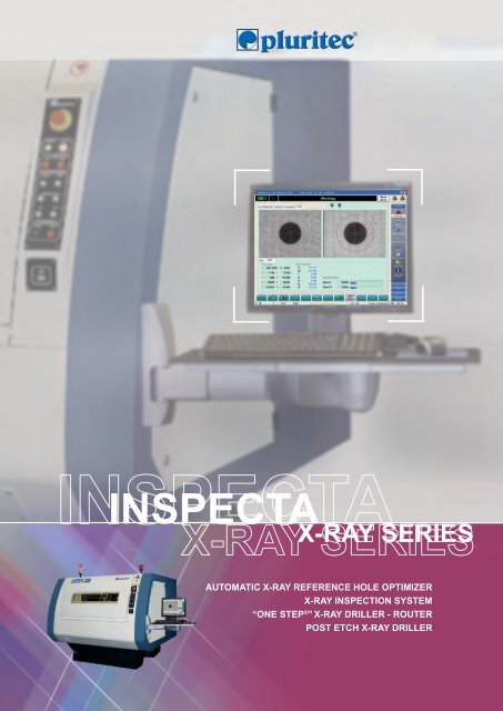
INSPECTA<br />
X-RAY SERIES<br />
AUTOMATIC X-RAY REFERENCE HOLE OPTIMIZER<br />
X-RAY INSPECTION SYSTEM<br />
“ONE STEP ® ” X-RAY DRILLER - ROUTER<br />
POST ETCH X-RAY DRILLER
2<br />
X-RAY SERIES<br />
ALL AXES WITH LINEAR MOTORS<br />
INSPECTA is the new Pluritec ® X-<strong>Ray</strong> drilling/routing<br />
machine.<br />
INSPECTA L<br />
INSPECTA HPL<br />
The wide range of confi gurations allows to have not<br />
only an X-<strong>Ray</strong> optimizer but also a real drilling machine<br />
assisted by X-<strong>Ray</strong>.<br />
ALL AXES WITH<br />
THE X-RAY SERIES<br />
INSPECTA L or HPL<br />
X-<strong>Ray</strong> inspection<br />
machine for optimized<br />
reference hole drilling<br />
This means maximum versatility and fl exibility that, in<br />
combination with a large working area, make<br />
INSPECTA the perfect tool to process multilayers<br />
boards.<br />
INSPECTA is designed to grant high accuracy and<br />
productivity (up to 5 panels/min).<br />
The machine can be equipped with 1 or 2 spindles.
X - RAY SERIES<br />
LINEAR MOTORS<br />
MAIN VERSIONS:<br />
INSPECTA COMBO L or HPL<br />
X-<strong>Ray</strong> inspection system with<br />
“ONE STEP ® ” drilling - routing<br />
package<br />
INSPECTA (COMBO), thanks to the ONE STEP ® system<br />
in combination with the independent heads and the<br />
versatility of the Pluritec CNC control it’s not only an<br />
X-<strong>Ray</strong> optimizer but also a driller and/or router.<br />
Very large panels can be processed by parking one head<br />
and using the other to cover the larger working area.<br />
Different spindles types are available.<br />
The main available<br />
confi gurations are:<br />
• INSPECTA L<br />
• INSPECTA HPL<br />
• INSPECTA COMBO L<br />
• INSPECTA COMBO HPL<br />
INSPECTA can be also used as a<br />
Post Etch Drilling machine<br />
INSPECTA<br />
X-RAY SERIES<br />
COMBO L<br />
Spindle<br />
CCD Camera<br />
Tooling plate<br />
X-<strong>Ray</strong> source<br />
COMBO HPL<br />
Spindle<br />
CCD Camera<br />
Tooling plate<br />
X-<strong>Ray</strong> source<br />
3
4<br />
Basement<br />
Independent heads<br />
X-<strong>Ray</strong> Camera<br />
A cast structure machine basement assures high<br />
stability to the X,Y, Z and X-<strong>Ray</strong> sources axes<br />
movement on linear motors.<br />
The Y axis movement is based on a Gantry system,<br />
thus allowing the X-<strong>Ray</strong> sources to cover the<br />
entire working area under the tooling plate.<br />
Two high speed air bearing spindles (drilling and/<br />
or routing) and two CCD Cameras provide a nearly<br />
simultaneous pads detection, to ensure an high<br />
productivity.<br />
Each spindle is housed on a structure that moves on two linear<br />
guides with four sliding blocks. This solution assures the highest Z<br />
axis movement accuracy.<br />
A high sensitive resolution X-<strong>Ray</strong> camera, with an<br />
integrated scintillator and a controller is able to:<br />
• Perform CCD over-exposure (for very thick panels).<br />
• Reduce the noise effect by averaging the process.<br />
All parameters are controlled by software.<br />
A special soft brushes pressure foot around the Camera has the<br />
important function to press the panel fl at against the tooling plate<br />
avoiding planarity problems that might affect the vision accuracy.<br />
X-<strong>Ray</strong> sources<br />
X-<strong>Ray</strong> microfocus sources are driven by linear motors.<br />
Thin and thick panels can be processed setting the<br />
parameters programmable inside the part-program.
X - RAY SERIES<br />
Vacuum device for panel locking<br />
Tool magazine<br />
Working area<br />
The panel is locked using of a vacuum device (Venturi<br />
system) that operates in the centre of the working<br />
area.<br />
Two laser beams, guide the operator to position the<br />
panel on machine table.<br />
In case of thin panels or inner layers a special<br />
vacuum system is available in order to keep the<br />
panel fl at and uniform on the tooling plate before<br />
processing it.<br />
A cassette (one for each spindle) holds 140 tools.<br />
Drill bit height, diameter and run-out are measured<br />
by a laser station during every tool change operation.<br />
INSPECTA<br />
X-RAY SERIES<br />
The maximum inspection area is 760 mm x 690 mm (29.92” x 27.2”) excluded a central area of<br />
150 mm (5.9”). Optionally a larger area is available.<br />
The drilling area is up to 1397 mm x 835 mm (55’’ x 32,9’’) excluded a central area of 150 mm x<br />
260 mm (5.9” x 10.24”).<br />
690 mm (27,2’’)<br />
Inspection area<br />
760 mm<br />
(29,92’’)<br />
150 mm (5,9’’)<br />
Forbidden area<br />
Drillng area<br />
1397 mm (55’’)<br />
150 mm (5,9’’)<br />
Customized “dead zone area”<br />
According to the customer needs the “dead zone area” can be customized in order to process<br />
any kind of panel on any internal area, i.e. when using multiple reference pads for the<br />
optimization of all internal patterns.<br />
260 mm (10,24’’)<br />
835 mm (32,9’’)<br />
5
6<br />
COMBO with “ONE STEP ® ” drilling-routung package<br />
The COMBO version is equipped with “ONE STEP ® ” the<br />
drilling - routing package (ONE STEP software, dedicated<br />
tooling plate, air bearing spindle, contact drilling system,<br />
surface CCD camera).<br />
Drilling/routing spindle<br />
According to the relevant confi guration, the machine can<br />
be equipped with a microdrilling spindle on one head and a<br />
routing spindle on the other head.<br />
The machine can also be use as regular two head drilling -<br />
routing machine.<br />
Contact drilling<br />
This system allows both, broken bit detection and controlled<br />
depth drilling.<br />
Any breakage/chipping of small diameter drill bits can be<br />
detected in real time.<br />
Pressure foot<br />
The spindle can be equipped with automatic bush exchange<br />
pressure foot.<br />
Surface Camera<br />
System for automatic alignment of single stack after the<br />
loading on the table. This provides the “ultimate” in perfect<br />
drilling of multilayer stacks, so eliminating any error due to<br />
the tooling plate.<br />
Moreover, the vision system allows the processing of<br />
particular applications, such as the drilling of holes related<br />
to the position of specifi ed targets (i.e. BGA products) and<br />
the routing of patterns related to the position of specifi ed<br />
references.<br />
Machine confi gurations<br />
INSPECTA<br />
MACHINE<br />
TYPE<br />
L 1<br />
HEADS<br />
SPINDLE TYPE<br />
Spindle1 | Spindle2<br />
180 krpm<br />
HPL 2 Independent 180 krpm<br />
COMBO L<br />
COMBO HPL<br />
1<br />
drilling and/or routing<br />
2 Independent<br />
drilling and/or routing<br />
Drilling:<br />
180 or 200 or 250 krpm<br />
Routing:<br />
80 or 125 krpm<br />
Drilling:<br />
180 or 200 or 250 krpm<br />
Routing:<br />
80 or 125 krpm<br />
-<br />
-<br />
X-RAY<br />
SOURCE<br />
1<br />
2<br />
1<br />
1
X - RAY SERIES<br />
Inspection methods<br />
Multiple inspection<br />
Rejection criteria<br />
The inspection methods available in the machine standard<br />
confi guration are:<br />
• Two symmetrical overlapped and staggered targets<br />
• More than two symmetrical or asymmetrical overlapped<br />
targets<br />
• More than two symmetrical or asymmetrical overlapped<br />
and staggered targets<br />
• Anti-rotation target<br />
Overlapped method is the most commonly adopted, while<br />
the staggered one is normally used to generate feed-back<br />
data either to the lamination process in case the machine<br />
inspects the Multilayer panels, or to the etching process in<br />
case the machine inspects the innerlayer in the post-etch<br />
drilling.<br />
New software capability for the inspection of multiple<br />
targets which allows the drilling of multiple reference<br />
optimized holes or, in case of the “one step X-<strong>Ray</strong> drilling/<br />
routing” application, directly compensate (offset + rotation<br />
+ scaling) the drilling/routing program on every single<br />
pattern of the circuit.<br />
During the inspection step (before drilling),<br />
INSPECTA cheks if the panel geometry is within the<br />
tolerances set by the operator.<br />
The causes of panel rejection can<br />
be as follows:<br />
• Dispersion tolerance<br />
• Pad to pad distance tolerance<br />
• Global tolerance<br />
INSPECTA<br />
X-RAY SERIES<br />
7
8<br />
Main features<br />
Control unit<br />
Drill on pad with/without offset<br />
In addition to the standard holes (drilled in the reference system<br />
based on the acquired targets) it is possible to drill exactly in the<br />
middle of target or with a given offset from it. This function is<br />
useful to drill the laser-via reference holes.<br />
Extended zone target search<br />
The extended zone search allows to process panels positioned on<br />
the working table with high misalignments (for instance panels<br />
with “fl ashes”). This function allows to search in surrounding<br />
areas when no pad is detected in the initial position with the<br />
standard fi eld of view.<br />
Panel shifting<br />
This is a very useful function that avoids the drilling burr on the<br />
bottom side of the panel (due to the repeated drilling in the<br />
same area which creates the absence of “backup material” under<br />
the panel to be drilled).<br />
The “panel shifting” automatically guides the placement of<br />
the panels and makes each time different their position on the<br />
working table equipped with backup panel.<br />
Classifi ed panels<br />
This useful function allows processed panels to be classifi ed<br />
according to three or more classes of user-defi ned tolerance.<br />
Example:<br />
Class A = ± 0.025 mm (1 mil)<br />
Class B = ± 0.050 mm (2 mils)<br />
Class C = ± 0.075 mm (3 mils)<br />
The panel classifi cation is made by drilling the processed panels<br />
with one or more dedicated holes according to the measured<br />
errors.<br />
Very powerful Pluritec® PCB Control<br />
CNC, with customized working cycles,<br />
integrated vision system, interactive graphic<br />
programming and online statistical analysis.
X - RAY SERIES<br />
APPLICATIONS<br />
One step X-<strong>Ray</strong> drilling/routing<br />
Flip Drilling<br />
The unique and sophisticated software package allows processing<br />
a multilayer panel in one step only.<br />
The panel is fi xed on the machine table via two pins and before<br />
running the drilling or routing program (like on a standard<br />
drilling or routing machine) the machine will detect and measure<br />
(via the X-<strong>Ray</strong> system) the reference targets in order to directly<br />
compensate (rotation, offset and possible scaling) the measured<br />
deformation.<br />
This new and unique capability allows to use the machine like a<br />
very accurate one spindle drilling/routing machine equipped with<br />
CCD camera; the big advantage is the very high drilling/routing<br />
accuracy that could not be achieved with the standard processes.<br />
The “Flip drilling” system is applied in presence of very small<br />
trough holes and thick multilayer panels. The drill bit fl ute length<br />
of small tools, in fact, does not allow the drilling of trough holes .<br />
Two or more references are measured by the X-ray vision system<br />
before starting the drilling of the top side and before the drilling<br />
of the bottom side of the panel.<br />
Manual measuring<br />
By means of a dedicated joy stick it is possible to execute manual<br />
X-ray measurements on multilayer panel, such as minimum<br />
annular ring (automatic calculation of the error), distances<br />
between holes, pads and others.<br />
Panel thickness measuring<br />
A special measuring device, available with the automatic<br />
Loading/Unloading system only, measures the thickness<br />
of the panel during panel pick-up operation; if the<br />
measured value is out of tolerance the panel is marked<br />
for its identifi cation.<br />
INSPECTA<br />
X-RAY SERIES<br />
1 . 5 6 2<br />
9
10<br />
Post Etch Drilling<br />
Automation<br />
<strong>Inspecta</strong> can be used also as a Post Etch<br />
Drilling machine.<br />
Compared to others post etch drilling<br />
machines available in the market<br />
<strong>Inspecta</strong> has a big advantage: the x-ray<br />
system.<br />
When processing a multilayer core, the<br />
possible mis-alignment between the top<br />
and bottom layers is compensated and<br />
the reference holes for the multilayer<br />
build-up are extremely accurate.<br />
In addition, a dedicated thin panel<br />
management system allows to place<br />
and remove an “entry panel” in order<br />
to grant:<br />
1) Flatness uniformity on the machine<br />
tooling plate for a very good drilling<br />
accuracy.<br />
2) Rigidity during the drilling for a very<br />
good hole quality.<br />
The entry panel is automatically placed<br />
on the innerlayer before drilling and<br />
automatically removed after the end of<br />
cycle.<br />
<strong>Inspecta</strong> L or HPL can be equipped<br />
with an automatic Loading/Unloading<br />
system that makes the machine very<br />
productive.<br />
The automation system in composed by:<br />
• Loading station where the panels<br />
to be processed are positioned on a<br />
moveable trolley.<br />
• Unloading station with a moveable<br />
trolley where the processed panels<br />
are positioned.<br />
• Rejection station where the rejected<br />
panels (out of tolerance) are<br />
positioned.<br />
Automatic entry panel<br />
management system<br />
Automatic entry panel<br />
management system<br />
Entry panel<br />
Vacuum system<br />
Vacuum system<br />
Machine table
X - RAY SERIES<br />
TECHNICAL SPECIFICATIONS<br />
INSPECTA<br />
X-RAY SERIES<br />
TECHNICAL FEATURES INSPECTA L/COMBO L INSPECTA HPL/COMBO HPL<br />
Inspection methods - Two symmetrical overlapped and staggered targets<br />
- More than two symmetrical or asymmetrical overlapped targets<br />
- More than two symmetrical or asymmetrical overlapped and staggered targets<br />
- Anti-rotation target<br />
- Multiple targets (multiple patterns) for independent drilling optimization<br />
Reference pad shape and diameter Circular 0.5 to 3.5 mm (0.0196” to 0.1378”)<br />
Panel rejection criteria Pad to pad, dispersion, global and overall tolerances<br />
Panel thickness From 0.1 mm** (0.00393”) up to 10 mm (0.4”)<br />
XL, XR and Y axes positioning speed 60 m/min (2362 in/min) with linear motors<br />
XL, XR and Y axes acceleration 1.5 g<br />
X-Y axes positioning accuracy 0.005 mm (0.196 mils) *<br />
X-Y axes positioning repeatability 0.004 mm (0.157 mils) *<br />
Z axis positioning speed 35 m/min (1378 in/min)<br />
Z axis acceleration 3 g<br />
DRILLING UNITS<br />
Air bearing drilling spindle<br />
180 krpm (standard) - 200 krpm - 250 krpm (option)<br />
Number of spindles<br />
1 2<br />
Routing spindle (option) 80 krpm - 125 krpm - HCT 60 Krpm synchronous<br />
Broken bit detection Contact drill (STD)<br />
Drilling diameters 0.1 ~ 6.35 mm (0.004” ~ 0.250”)<br />
TOOL CHANGE<br />
Number of tools available 140 drill bits on cassette (standard) 280 drill bits on cassette per spindle (option)<br />
Laser station For drill bit height, diameter and dynamic run-out measuring<br />
CCD CAMERA AND X-RAY SYSTEM<br />
CCD Camera<br />
High resolution CCD Camera with integrated high resolution scintillator and controller<br />
Active area: 9.6 x 12.8 mm (0.3779” x 0.5039”) - Resolution: 15LP/mm, 33um<br />
Number of CCD Camera<br />
X-<strong>Ray</strong> system<br />
Number of X-<strong>Ray</strong> sources<br />
1 2 (<strong>Inspecta</strong> HPL) - 1 or 2 (COMBO HPL)<br />
X-<strong>Ray</strong> micro-focus sources driven by linear motors<br />
Focal spot size, optical: 50 m x 50 m (1.97 x 1.97 mils) - Wave angle: 20°<br />
1 2 (<strong>Inspecta</strong> HPL) - 1 or 2 (COMBO HPL)<br />
CONTROL UNIT<br />
CNC type Pluritec ® PCB Control<br />
Operatng system Windows 7 professional based O.S. and proprietary platform for integrated<br />
machine/axis/vision management<br />
Monitor 17” LCD colour monitor<br />
CPU Intel Pentium Dual Core 1.8 GHZ<br />
GENERAL SPECIFICATIONS<br />
Electrical power supply 400 V - 50 Hz - 3 phase - different power supply on request<br />
Power requirements 6.5 kVA (manual machine)<br />
8 kVA (manual machine)<br />
8 kVA (with automation)<br />
9.5 kVA (with automation)<br />
Compressed air pressure 7 bar (102 PSI)<br />
Air consumption 450 NI/min (15.9 CFM) manual machine 600 NI/min (21.2 CFM) manual machine<br />
1250 NI/min (44.1 CFM) with automation 1400 NI/min (49.4 CFM) with automation<br />
Machine dimensions 2820 x 2140 x 2300 mm (111” x 84.3” x 90.6”)<br />
Noise level < 75 dB<br />
Total weight (base machine) 3100 kg (6800 Ib) 3200 kg (7000 Ib)<br />
Total weight with L/U system 5600 kg (12330 Ib) 5700 kg (12550 Ib)<br />
(*) According to ISO 230/2<br />
Data is not binding. Pluritec ® reserves the right to change the present information without notice.<br />
11