

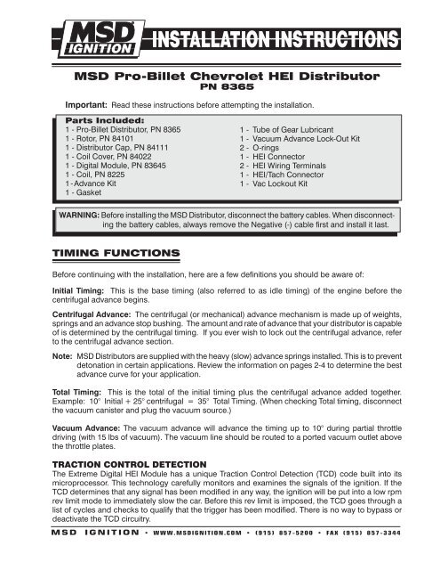
MSD Pro-Billet Chevrolet HEI Distributor PN 8365 - Set your timing
MSD Pro-Billet Chevrolet HEI Distributor PN 8365 - Set your timing
MSD Pro-Billet Chevrolet HEI Distributor PN 8365 - Set your timing

You also want an ePaper? Increase the reach of your titles
YUMPU automatically turns print PDFs into web optimized ePapers that Google loves.
<strong>MSD</strong> <strong>Pro</strong>-<strong>Billet</strong> <strong>Chevrolet</strong> <strong>HEI</strong> <strong>Distributor</strong><br />
<strong>PN</strong> <strong>8365</strong><br />
Important: Read these instructions before attempting the installation.<br />
Parts Included:<br />
1 - <strong>Pro</strong>-<strong>Billet</strong> <strong>Distributor</strong>, <strong>PN</strong> <strong>8365</strong><br />
1 - Rotor, <strong>PN</strong> 84101<br />
1 - <strong>Distributor</strong> Cap, <strong>PN</strong> 84111<br />
1 - Coil Cover, <strong>PN</strong> 84022<br />
1 - Digital Module, <strong>PN</strong> 83645<br />
1 - Coil, <strong>PN</strong> 8225<br />
1 - Advance Kit<br />
1 - Gasket<br />
TIMING FUNCTIONS<br />
1 - Tube of Gear Lubricant<br />
1 - Vacuum Advance Lock-Out Kit<br />
2 - O-rings<br />
1 - <strong>HEI</strong> Connector<br />
2 - <strong>HEI</strong> Wiring Terminals<br />
1 - <strong>HEI</strong>/Tach Connector<br />
1 - Vac Lockout Kit<br />
WARNING: Before installing the <strong>MSD</strong> <strong>Distributor</strong>, disconnect the battery cables. When disconnecting<br />
the battery cables, always remove the Negative (-) cable first and install it last.<br />
Before continuing with the installation, here are a few definitions you should be aware of:<br />
Initial Timing: This is the base <strong>timing</strong> (also referred to as idle <strong>timing</strong>) of the engine before the<br />
centrifugal advance begins.<br />
Centrifugal Advance: The centrifugal (or mechanical) advance mechanism is made up of weights,<br />
springs and an advance stop bushing. The amount and rate of advance that <strong>your</strong> distributor is capable<br />
of is determined by the centrifugal <strong>timing</strong>. If you ever wish to lock out the centrifugal advance, refer<br />
to the centrifugal advance section.<br />
Note: <strong>MSD</strong> <strong>Distributor</strong>s are supplied with the heavy (slow) advance springs installed. This is to prevent<br />
detonation in certain applications. Review the information on pages 2-4 to determine the best<br />
advance curve for <strong>your</strong> application.<br />
Total Timing: This is the total of the initial <strong>timing</strong> plus the centrifugal advance added together.<br />
Example: 10° Initial + 25° centrifugal = 35° Total Timing. (When checking Total <strong>timing</strong>, disconnect<br />
the vacuum canister and plug the vacuum source.)<br />
Vacuum Advance: The vacuum advance will advance the <strong>timing</strong> up to 10° during partial throttle<br />
driving (with 15 lbs of vacuum). The vacuum line should be routed to a ported vacuum outlet above<br />
the throttle plates.<br />
TracTIon conTrol DeTecTIon<br />
The Extreme Digital <strong>HEI</strong> Module has a unique Traction Control Detection (TCD) code built into its<br />
microprocessor. This technology carefully monitors and examines the signals of the ignition. If the<br />
TCD determines that any signal has been modified in any way, the ignition will be put into a low rpm<br />
rev limit mode to immediately slow the car. Before this rev limit is imposed, the TCD goes through a<br />
list of cycles and checks to qualify that the trigger has been modified. There is no way to bypass or<br />
deactivate the TCD circuitry.<br />
M S D I G N I T I O N • www.msdignition.com • (915) 857-5200 • FAX (915) 857-3344
CHOOSING AN ADVANCE CURVE<br />
INSTALLATION INSTRUCTIONS<br />
The function of the advance curve is to match the ignition <strong>timing</strong> to the burning rate of the fuel and<br />
speed (rpm) of the engine. Any factor that changes the burning rate of the fuel or the engine speed<br />
can cause a need for an ignition <strong>timing</strong> change. Figure 1 shows some of the factors that will affect<br />
engine <strong>timing</strong>.<br />
FACTOR Advance Timing Retard Timing<br />
For For<br />
Cylinder Pressure Low High<br />
Vacuum High Low<br />
Energy of Ignition Low High<br />
Fuel Octane High Low<br />
Mixture (Air/Fuel) Rich Lean<br />
Temperature Cool Hot<br />
Combustion Chamber Shape Open Compact<br />
Spark Plug Location Offset Center<br />
Combustion Turbulence Low High<br />
Load Light Heavy<br />
Figure 1 Ignition Timing Factors.<br />
As you can see from the chart, most factors will change throughout the range of the engine operation.<br />
The <strong>timing</strong> mechanism of the distributor must make <strong>timing</strong> changes based on these factors.<br />
Example: An engine has 11:1 compression with a high energy ignition. With the specifications given,<br />
you will have to retard the <strong>timing</strong> for the high compression and high energy ignition. By comparing<br />
the engine’s specifications against the chart, a usable <strong>timing</strong> guideline can be found. Engines with<br />
a combination of items from both columns will require a <strong>timing</strong> that is set in the mid range.<br />
Obviously a full technical explanation of correct ignition <strong>timing</strong> would be very complicated. The best<br />
way to arrive at a suitable ignition curve for <strong>your</strong> engine is to use the Ignition Timing Factors Chart<br />
as a guide and compare it to the Advance Graphs in Figure 4 until a suitable curve is found. When<br />
selecting <strong>your</strong> advance curve, use detonation (engine ping) as an indicator of too much advance,<br />
and a decrease in power as an indicator of too little advance.<br />
TIPs on selecTIng an aDvance curve<br />
• Use as much initial advance as possible without encountering excessive starter load.<br />
• Start the centrifugal advance just above the idle rpm.<br />
• The starting point of the centrifugal advance curve is controlled by the installed length and<br />
tension of the spring.<br />
• How quickly the centrifugal advance (slope) comes in is controlled by the spring stiffness. The<br />
stiffer the spring, the slower the advance curve.<br />
• The amount of advance is controlled by the advance bushing. The bigger the bushing, the<br />
smaller the amount of advance.<br />
M S D I G N I T I O N • www.msdignition.com • (915) 857-5200 • FAX (915) 857-3344
INSTALLATION INSTRUCTIONS<br />
CENTRIFUGAL ADVANCE CURVE<br />
selecTIng The aDvance sPrIngs<br />
The rate, or how quick the advance comes in<br />
is determined by the type of springs which are<br />
installed on the distributor. The <strong>MSD</strong> distributors<br />
are equipped with two Heavy Silver springs<br />
installed. These will give you the slowest advance<br />
curve possible (Figure 2). The parts kit contains<br />
two additional sets of springs which can be used<br />
to match the advance curve to <strong>your</strong> particular<br />
application. Refer to the Spring Combination<br />
Chart (Figure 3) for combinations that can be<br />
achieved.<br />
To change the springs, remove the cap and rotor<br />
and use needlenose pliers to remove the springs.<br />
Be sure the new springs seat in the groove on<br />
the pin.<br />
Figure 4 Advance Curves.<br />
Timing Curve From Factory<br />
Figure 2 The Factory Equipped Curve.<br />
SPRING COMBINATION RATE OF ADVANCE FIGURE 4<br />
2- Heavy Silver SLOWEST A<br />
1- Heavy Silver B<br />
1- Light Blue<br />
1-Heavy Silver C<br />
1-Light Silver<br />
2- Light Blue D<br />
1- Light Silver E<br />
1- Light Blue<br />
2- Light Silver FASTEST F<br />
Figure 3 Spring Combination Chart.<br />
M S D I G N I T I O N • www.msdignition.com • (915) 857-5200 • FAX (915) 857-3344
selecTIng The aDvance sToP<br />
BushIng<br />
Three different advance stop bushings are supplied<br />
in the distributor kit. The distributor comes with a<br />
Blue (21°) bushing already installed. If a different<br />
amount of centrifugal advance is desired, follow the<br />
next procedure to change the bushings. The chart<br />
in Figure 5 gives the size and approximate degrees<br />
for the corresponding bushings.<br />
changIng The aDvance sToP<br />
BushIngs<br />
1. Remove the distributor cap and rotor.<br />
2. Remove the locknut and washer on the bottom<br />
of the advance assembly (Figure 6).<br />
3. Remove the bushing and install the new one.<br />
Install the washer and locknut.<br />
lockIng ouT The cenTrIfugal<br />
aDvance<br />
1. Remove the advance components including the<br />
springs, weights and the advance stop bushing<br />
from the advance assembly.<br />
2. Remove the roll-pin from the drive gear and<br />
remove the gear from the shaft.<br />
3. Slide the shaft two inches out of the housing.<br />
4. Rotate the shaft 180° and insert the advance stop<br />
bushing pin into the small hole on the advance<br />
plate (Figure 7).<br />
5. Install the locknut and washer to the advance stop<br />
bushing pin. This locks the advance in place.<br />
6. Install the drive gear and roll-pin.<br />
Note: If you want to lock out the vacuum advance<br />
of the <strong>Distributor</strong>, see page 7.<br />
INSTALLATION INSTRUCTIONS<br />
BUSHING SIZE APPROXIMATE<br />
CRANKSHAFT<br />
DEGREES<br />
Red-Smallest 28<br />
Silver 25<br />
Blue 21<br />
Black-Largest 18<br />
Figure 5 Advance Stop Bushing Chart.<br />
Figure 6 Changing the Advance Stop Bushing.<br />
Figure 6 Locking Out the Centrifugal Advance.<br />
Figure 7 Locking Out the Advance.<br />
M S D I G N I T I O N • www.msdignition.com • (915) 857-5200 • FAX (915) 857-3344
INSTALLATION INSTRUCTIONS<br />
INSTALLING THE DISTRIBUTOR<br />
1. Remove the existing distributor cap without<br />
disconnecting any of the spark plug wires.<br />
2. With the cap off, crank the engine until the<br />
rotor is aimed at a fixed point on the engine or<br />
firewall. Note this position by making a mark<br />
(Figure 8).<br />
3. Place the distributor cap back on and note<br />
which plug wire the rotor is pointing to. MARK<br />
THE SPARK PLUG WIRES and remove the<br />
distributor cap.<br />
4. Disconnect the wiring from the distributor.<br />
5. Loosen the distributor hold down clamp and<br />
slide the clamp out of the way.<br />
6. Lift the distributor out of the engine. Note that<br />
the rotor rotates as you lift the distributor out.<br />
This is due to the helical cut gear and should<br />
be taken into consideration when installing the<br />
new distributor.<br />
7. Install the gasket and apply a liberal amount of<br />
the supplied lubricant to the distributor gear.<br />
(The supplied O-rings can only be used if<br />
the block has been modified as shown in<br />
Figure 9.)<br />
8. Install the distributor making sure that the<br />
rotor comes to rest pointing at the same<br />
fixed mark. If the distributor will not fully seat<br />
with the rotor pointing to the marked position,<br />
you may need to rotate the oil pump shaft<br />
until the rotor lines up and the distributor fully<br />
seats.<br />
9. Position and tighten the hold down clamp onto<br />
the distributor.<br />
10. Install the distributor cap and spark plug wires<br />
one at a time to ensure correct location.<br />
11. Connect a switched 14-gauge wire from<br />
a 12 volt source to the B+ terminal of the<br />
<strong>Distributor</strong> Cap (Figure 10).<br />
Figure 8 Marking the Rotor Location.<br />
Figure 9 Modified Block for use with O-Rings.<br />
M S D I G N I T I O N • www.msdignition.com • (915) 857-5200 • FAX (915) 857-3344
Figure 10 General Wire Installation.<br />
Figure 11 Wiring to an <strong>MSD</strong> Ignition Control.<br />
INSTALLATION INSTRUCTIONS<br />
M S D I G N I T I O N • www.msdignition.com • (915) 857-5200 • FAX (915) 857-3344
INSTALLATION INSTRUCTIONS<br />
vacuuM aDvance lockouT<br />
If you do not want to use the vacuum advance canister,<br />
<strong>MSD</strong> has supplied a lockout mechanism.<br />
1. Remove the three Phillips screws that hold the<br />
advance canister (Figure 12).<br />
2. Remove the aluminum hex shaped spacer from<br />
the housing.<br />
3. Install the longer hex spacer supplied in the parts<br />
bag in the threaded hole next to where the original<br />
spacer was mounted. Use the same Phillips<br />
screw.<br />
4. Install the plastic cover to seal the distributor<br />
housing using the original advance hold down<br />
screws (Figure 13).<br />
Note: Do not forget to plug the original vacuum<br />
advance hose.<br />
aDjusTaBle rev lIMITer<br />
The Extreme Output <strong>HEI</strong> Module features an<br />
adjustable rev limiter. The limit is adjusted through<br />
the small rotary dial on the end of the module (Figure<br />
14). This limiter is adjustable from 5,000 - 10,000<br />
rpm. Turning the rotary dial clockwise raises the<br />
limit, CCW lowers the rpm limit. It doesn’t take much<br />
movement for changes so it is recommended to start<br />
low and bump the rev limit up a little at a time.<br />
HEX<br />
sPACER<br />
Figure 12 Removing the Vacuum Canister.<br />
VACUUM ADVANCE HOLE<br />
(NOt UsED)<br />
LONGER<br />
HEX sPACER<br />
Figure 13 Vacuum Lockout Installed.<br />
Figure 14 Adjusting the Rev Limiter.<br />
CANistER<br />
sCREws<br />
LOCKOUt<br />
COVER<br />
M S D I G N I T I O N • www.msdignition.com • (915) 857-5200 • FAX (915) 857-3344
TECH NOTES<br />
_________________________________________________________________________________________________________________________<br />
_________________________________________________________________________________________________________________________<br />
_________________________________________________________________________________________________________________________<br />
_________________________________________________________________________________________________________________________<br />
_________________________________________________________________________________________________________________________<br />
_________________________________________________________________________________________________________________________<br />
_________________________________________________________________________________________________________________________<br />
_________________________________________________________________________________________________________________________<br />
_________________________________________________________________________________________________________________________<br />
_________________________________________________________________________________________________________________________<br />
_________________________________________________________________________________________________________________________<br />
_________________________________________________________________________________________________________________________<br />
_________________________________________________________________________________________________________________________<br />
_________________________________________________________________________________________________________________________<br />
_________________________________________________________________________________________________________________________<br />
service<br />
In case of malfunction, this <strong>MSD</strong> component will be repaired free of charge according to the terms of the warranty.<br />
When returning <strong>MSD</strong> components for warranty service, <strong>Pro</strong>of of Purchase must be supplied for verification. After<br />
the warranty period has expired, repair service is based on a minimum and maximum fee.<br />
All returns must have a Return Material Authorization (RMA) number issued to them before<br />
being returned. To obtain an RMA number please contact <strong>MSD</strong> Customer Service at 1 (888) <strong>MSD</strong>-7859 or<br />
visit our website at www.msdignition.com/rma to automatically obtain a number and shipping information.<br />
When returning the unit for repair, leave all wires at the length in which you have them installed. Be sure to include<br />
a detailed account of any problems experienced, and what components and accessories are installed on the vehicle.<br />
The repaired unit will be returned as soon as possible using Ground shipping methods (ground shipping is covered<br />
by warranty). For more information, call <strong>MSD</strong> Ignition at (915) 855-7123. <strong>MSD</strong> technicians are available from 7:00<br />
a.m. to 6:00 p.m. Monday - Friday (mountain time).<br />
limited Warranty<br />
<strong>MSD</strong> IGNITION warrants this product to be free from defects in material and workmanship under its intended normal<br />
use*, when properly installed and purchased from an authorized <strong>MSD</strong> dealer, for a period of one year from the date<br />
of the original purchase. This warranty is void for any products purchased through auction websites. If found to be<br />
defective as mentioned above, it will be repaired or replaced at the option of <strong>MSD</strong> Ignition. Any item that is covered<br />
under this warranty will be returned free of charge using Ground shipping methods.<br />
This shall constitute the sole remedy of the purchaser and the sole liability of <strong>MSD</strong> Ignition. To the extent permitted<br />
by law, the foregoing is exclusive and in lieu of all other warranties or representation whether expressed or implied,<br />
including any implied warranty of merchantability or fitness. In no event shall <strong>MSD</strong> Ignition or its suppliers be liable<br />
for special or consequential damages.<br />
*Intended normal use means that this item is being used as was originally intended and for the original application<br />
as sold by <strong>MSD</strong> Ignition. Any modifications to this item or if it is used on an application other than what <strong>MSD</strong> Ignition<br />
markets the product, the warranty will be void. It is the sole responsibility of the customer to determine that this item<br />
will work for the application they are intending. <strong>MSD</strong> Ignition will accept no liability for custom applications.<br />
M S D I G N I T I O N • www.msdignition.com • (915) 857-5200 • FAX (915) 857-3344<br />
© 2007 Autotronic Controls Corporation<br />
FRM28975 Revised 09/07 Printed in U.S.A.