“ giflex ® ” ge-t flexible couplings
“ giflex ® ” ge-t flexible couplings
“ giflex ® ” ge-t flexible couplings

You also want an ePaper? Increase the reach of your titles
YUMPU automatically turns print PDFs into web optimized ePapers that Google loves.
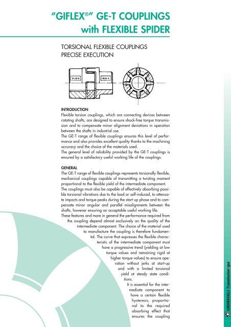
<strong>“</strong>GIFLEX <strong>®</strong> <strong>”</strong> GE-T COUPLINGS<br />
with FLEXIBLE SPIDER<br />
TORSIONAL FLEXIBLE COUPLINGS<br />
PRECISE EXECUTION<br />
INTRODUCTION<br />
Flexible torsion <strong>couplings</strong>, which are connecting devices between<br />
rotating shafts, are designed to ensure shock-free torque transmission<br />
and to compensate minor alignment deviations in operation<br />
between the shafts in industrial use.<br />
The GE-T ran<strong>ge</strong> of <strong>flexible</strong> <strong>couplings</strong> ensures this level of performance<br />
and also provides excellent quality thanks to the machining<br />
accuracy and the choice of the materials used.<br />
The <strong>ge</strong>neral level of reliability provided by the GE-T <strong>couplings</strong> is<br />
ensured by a satisfactory useful working life of the <strong>couplings</strong>.<br />
GENERAL<br />
The GE-T ran<strong>ge</strong> of <strong>flexible</strong> <strong>couplings</strong> represents torsionally <strong>flexible</strong>,<br />
mechanical <strong>couplings</strong> capable of transmitting a twisting moment<br />
proportional to the <strong>flexible</strong> yield of the intermediate component.<br />
The <strong>couplings</strong> must also be capable of effectively absorbing possible<br />
torsional vibrations due to the load or self-induced, to attenuate<br />
impacts and torque peaks during the start-up phase and to compensate<br />
minor angular and parallel misalignments between the<br />
shafts, however ensuring an acceptable useful working life.<br />
These features and more in <strong>ge</strong>neral the performance required from<br />
the coupling depend almost exclusively on the quality of the<br />
intermediate component. The choice of the material used<br />
to manufacture the coupling is therefore fundamental.<br />
The curve that expresses the <strong>flexible</strong> characteristic<br />
of the intermediate component must<br />
have a progressive trend (yielding at low<br />
torque values and remaining rigid at<br />
higher torque values) to ensure operation<br />
without jerks at start-up<br />
and with a limited torsional<br />
yield at steady state conditions.<br />
It is essential for the intermediate<br />
component to<br />
have a certain <strong>flexible</strong><br />
hysteresis, proportional<br />
to the required<br />
absorbing effect that<br />
ensures the coupling<br />
CHIARAVALLI Trasmissioni spa
CHIARAVALLI Trasmissioni spa<br />
<strong>“</strong>GIFLEX <strong>®</strong> <strong>”</strong> GE-T FLEXIBLE COUPLINGS<br />
can efficiently absorb possible torsional oscillations. Furthermore,<br />
the useful working life of the coupling depends on the <strong>flexible</strong> yield<br />
of the material comprising the intermediary component. The physical<br />
characteristics as described above are frequently in contrast<br />
with each other and compared with other basic mechanical and<br />
technological parameters. The performance of the intermediary<br />
component therefore cannot be adapted to the variety of operating<br />
conditions when only one type of material is used and therefore the<br />
materials adopted for the <strong>flexible</strong> ring <strong>ge</strong>ar must be differentiated.<br />
A selected thermoplastic elastomer is selected to meet medium level<br />
needs in the basic execution. This refers to an elastomer with<br />
medium rigidity, characterised by an optimum internal dampening<br />
effect, resistant to a<strong>ge</strong>ing, to fatigue, to abrasion, as well as<br />
hydrolysis and to the principal chemical a<strong>ge</strong>nts with special reference<br />
to oils and ozone. Operating temperatures lying between<br />
–40°C and +125°C with brief peaks of up to 150°C are permitted<br />
in the case of <strong>couplings</strong> in the base execution. Alternative mixes<br />
capable of meeting every practical need have been designed and<br />
are available on request for use in extremely demanding operating<br />
conditions, or for needs that exceed avera<strong>ge</strong> requirements.<br />
OPERATING AND ASSEMBLY CONDITIONS<br />
Operation of the <strong>flexible</strong> torsion <strong>couplings</strong>, such as the GE-T type<br />
or similar <strong>couplings</strong> is characterised by a proportional feature<br />
between the twisting torque and the torsion angle and by the ability<br />
to compensate limited angular and radial misalignments.<br />
Key features of equal importance, but which are more difficult to<br />
interpret are represented by the absorbing factor and the natural<br />
frequency or resonance. To qualify its <strong>couplings</strong>, CHIARAVALLI<br />
Trasmissioni spa declares permitted twisting torque values correlated<br />
to well defined torsion angle values, which has the limiting<br />
value of 5° corresponding to the maximum torque value. This provides<br />
a valid guide for the progressive characteristic of the <strong>flexible</strong><br />
curve. The maximum permitted values are shown in the case of the<br />
angular and radial misalignments, with the warning that these refer<br />
to extreme values that cannot be added to<strong>ge</strong>ther (only angular<br />
compensation or only radial compensation) and apply to<br />
"standard" operating conditions characterised by the following:<br />
operating torque not exceeding the nominal<br />
torque, a rotating speed of less than 1,450 r.p.m<br />
and coupling temperature not exceeding<br />
40°C. The maximum rotating speed<br />
expressed in r.p.m. that corresponds to<br />
a maximum peripheral speed of 30<br />
m/sec. is indicated for each coupling<br />
of the GE-T ran<strong>ge</strong>. This<br />
speed can be achieved with a<br />
sufficient safety margin<br />
compared to the dan<strong>ge</strong>r of<br />
failure due to centrifugal<br />
force stress thanks to<br />
the characteristics of<br />
the material used. Class<br />
G 2.5 dynamic balancing<br />
in compliance with
<strong>“</strong> GIFLEX <strong>®</strong> <strong>”</strong> GE-T FLEXIBLE COUPLINGS<br />
ISO 1940 is recommended despite the fact that the half-<strong>couplings</strong><br />
are fully machined on both external surfaces, if the actual operating<br />
speed exceeds 2.800 r.p.m.<br />
COUPLING SELECTION AND SIZING CRITERIA<br />
Couplings are sized on the basis of the physical laws of mechanics<br />
and the resistance of the materials and also complies with the<br />
provisions established in the DIN 740 standards Sheet 2.<br />
The coupling is selected on the basis of the criteria, which establishes<br />
that the maximum permitted stress is never exceeded even in<br />
the most demanding operating conditions. It follows that the nominal<br />
torque declared for the coupling must be compared with a<br />
reference torque that takes into account the overloads due to the<br />
way the load is exerted and the operating conditions. The reference<br />
torque is obtained by multiplying the operating torque by a<br />
series of multiplying factors depending on the nature of the load<br />
or on the ambient temperature conditions.<br />
Symbols:TKN = coupling maximum torque (Nm)<br />
TK max = coupling maximum torque (Nm)<br />
TKw = torque with coupling inversion (Nm)<br />
TLN = driven side operating torque (Nm)<br />
TLs = driven side static torque (Nm)<br />
TAs = motor side static torque (Nm)<br />
Ts = plant static torque (Nm)<br />
PLn = driven side operating power (kW)<br />
nLn = driven side rotating speed (r.p.m.)<br />
St = temperature factor<br />
SA = motor side impact factor<br />
SL = driven side impact factor<br />
Sz = start-up factor<br />
MA = control side mass factor<br />
ML = driven side mass factor<br />
LOAD DUE TO NOMINAL TORQUE<br />
The permitted nominal coupling torque TKN must<br />
apply for any operating temperature value equal<br />
to or greater than the driven side operating<br />
torque TLN.<br />
TLN = 9549 ( PLn ) [Nm]<br />
nLn<br />
JL<br />
JA+JL<br />
JA<br />
JA+JL<br />
The following condition must<br />
be satisfied, where St represents<br />
the temperature factor,<br />
to take into account<br />
overloads due to the<br />
operating temperature<br />
for the coupling.<br />
TKN = > TLN * St<br />
CHIARAVALLI Trasmissioni spa
CHIARAVALLI Trasmissioni spa<br />
<strong>“</strong> GIFLEX <strong>®</strong> <strong>”</strong> GE-T FLEXIBLE COUPLINGS<br />
NAME<br />
LOAD<br />
CONDITION<br />
START-UP LOAD<br />
The drive motor delivers a drive torque during the start-up transient<br />
period, which is a multiple of the nominal torque and depends on<br />
the way the masses are distributed. A similar situation occurs in the<br />
braking phase therefore, these two phases are characterised by<br />
torque impacts that have an intensity which depends on the distribution<br />
of the masses on the drive side MA and on the driven side<br />
ML, as well as the frequency of the number of start-ups on which<br />
the start-up factor Sz depends. The static torques for the drive side<br />
and the driven side are expressed by the following relationships:<br />
- drive side TS = TAS *MA *SA<br />
- driven side TS = TLS *MM *SL<br />
MA and ML are assumed to be equal to 1, to a first approximation,<br />
and if the distribution of the masses is unknown. The SA factor<br />
can be assumed as being equal to the relationship between the<br />
start-up torque and the nominal torque in the case of drives based<br />
on an electric motor.<br />
LOAD CAUSED BY TORQUE IMPACTS<br />
The permitted nominal coupling torque TKN max must be equal to<br />
or greater than the start-up torque increased by the temperature<br />
factor and by St and by the start-up factor Sz for any operating<br />
temperature value.<br />
TKN max > TS *St *Sz<br />
Consult the CHIARAVALLI Trasmissioni Technical Department for<br />
operating conditions that foresee periodic variations or torque<br />
inversions, as well as alternate torsional stresses.<br />
INDICATIVE VALUES FOR ADJUSTMENT FACTORS:<br />
SYMBOL DEFINITION<br />
Temperature St. St. 1 1.2 1.4 1.8<br />
Factor °C -30<br />
+30<br />
+40 +80 +120<br />
Start-up Sz.<br />
Number of start-ups per hour<br />
Factor Start-up/hr. 100 200 400 800<br />
Sz. 1 1.2 1.4 1.6<br />
Impact SA/SL<br />
Factor Minor start-up impacts<br />
Medium start-up impacts<br />
Major start-up impacts<br />
OPERATING CONDITIONS<br />
SERVICE FACTORS<br />
TYPE OF DRIVE<br />
Electric motor Diesel engine<br />
UNIFORM Regular operation without impacts or overloads 1.25 1.5<br />
LIGHT Regular operation with minor and infrequent impacts and overloads 1.50 2.0<br />
MEDIUM Irregular operation with medium overloads for a short duration and frequent but moderate impacts 2.0 2.5<br />
HEAVY Markedly irregular operation with very frequent impacts and overloads and of major intensity. 2.5 3.0<br />
SA/SL<br />
1.5<br />
1.8<br />
2.2
<strong>“</strong> GIFLEX <strong>®</strong> <strong>”</strong> GE-T FLEXIBLE COUPLINGS<br />
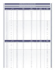
94 SHORE A BLACK SPIDER THERMOPLASTIC RUBBER<br />
TYPE<br />
19/24<br />
24/32<br />
28/38<br />
38/45<br />
42/55<br />
48/60<br />
55/70<br />
65/75<br />
75/90<br />
90/100<br />
Max.<br />
R.p.m.<br />
No.<br />
(min -1 )<br />
14000<br />
10600<br />
8500<br />
7100<br />
6000<br />
5600<br />
4750<br />
4250<br />
3550<br />
2800<br />
Torsion<br />
Angle<br />
TKN TKmax<br />
3.0° 5°<br />
Toothed<br />
Star<br />
Hardness<br />
TECHNICAL DATA (G 25 CAST IRON HUBS)<br />
TKN<br />
Norm.<br />
Twisting Moment<br />
MAX<br />
TKmax<br />
TKW<br />
with<br />
Inversion<br />
1.0<br />
TKN<br />
Torsional Rigidity<br />
(kNm/rad)<br />
0.75<br />
TKN<br />
0.5<br />
TKN<br />
0.25<br />
TKN<br />
b<br />
mm<br />
Maximum<br />
misalignment<br />
Radial<br />
b<br />
mm<br />
94 10 20 2.6 0.68 0.57 0.44 0.28 1.2 0.2 1.2°<br />
94 35 70 9 2.19 1.82 1.40 0.90 1.4 0.2 0.9°<br />
94 95 190 25 5.20 4.31 3.32 2.12 1.5 0.25 0.9°<br />
94 190 380 49 10.00 8.30 6.39 4.08 1.8 0.28 1.0°<br />
94 265 530 69 17.00 14.11 10.86 6.94 2.0 0.32 1.0°<br />
94 310 620 81 20.00 16.59 12.77 8.16 2.1 0.36 1.1°<br />
94 410 820 105 21.99 18.25 14.05 8.98 2.2 0.38 1.1°<br />
94 625 1250 163 28.20 23.39 18.01 11.51 2.6 0.42 1.2°<br />
94 975 1950 254 67.99 56.41 43.44 27.75 3.0 0.48 1.2°<br />
94 2400 4800 624 110.0 91.26 70.27 44.89 3.4 0.50 1.2°<br />
Axial<br />
displacement<br />
Angular<br />
γ°<br />
CHIARAVALLI Trasmissioni spa
CHIARAVALLI Trasmissioni spa<br />
<strong>“</strong> GIFLEX <strong>®</strong> <strong>”</strong> GE-T FLEXIBLE COUPLINGS<br />
96 SHORE A RED SPIDER THERMOPLASTIC RUBBER<br />
96 SHORE A YELLOW SPIDER POLYURETHANE<br />
TYPE<br />
19/24<br />
24/32<br />
28/38<br />
38/45<br />
42/55<br />
48/60<br />
55/70<br />
65/75<br />
75/90<br />
90/100<br />
Max.<br />
R.p.m.<br />
n.<br />
(min -1 )<br />
14000<br />
10600<br />
8500<br />
7100<br />
6000<br />
5600<br />
4750<br />
4250<br />
3550<br />
2800<br />
Torsion<br />
Angle<br />
TKN TKmax<br />
3.0° 5°<br />
Toothed<br />
Star<br />
Hardness<br />
TECHNICAL DATA (G 25 CAST IRON HUBS)<br />
TKN<br />
Norm.<br />
Twisting Moment<br />
MAX<br />
TKmax<br />
TKW<br />
with<br />
Inversion<br />
1.0<br />
TKN<br />
Torsional Rigidity<br />
(kNm/rad)<br />
0.75<br />
TKN<br />
0.5<br />
TKN<br />
0.25<br />
TKN<br />
Maximum<br />
misalignment<br />
Radial<br />
b<br />
mm<br />
96 17 34 4.4 1.09 0.90 0.68 0.42 1.2 0.2 1.2°<br />
96 60 120 16 3.70 3.04 2.31 1.44 1.4 0.2 0.9°<br />
96 160 320 42 9.5 7.80 5.92 3.68 1.5 0.25 0.9°<br />
96 325 650 85 29.0 23.8 18.06 11.24 1.8 0.28 1.0°<br />
96 450 900 117 40.5 33.24 25.21 15.70 2.0 0.32 1.0°<br />
96 525 1050 137 48.56 39.86 30.23 18.82 2.1 0.36 1.1°<br />
96 625 1250 163 52.78 43.32 32.86 20.46 2.2 0.38 1.1°<br />
95 640 1280 166 57.5 47.19 35.80 22.29 2.6 0.42 1.2°<br />
95 1465 2930 381 150.0 123.12 93.39 58.14 3.0 0.48 1.2°<br />
95 3600 7200 936 250.0 205.19 155.65 96.90 3.4 0.50 1.2°<br />
Axial<br />
displacement<br />
b<br />
mm<br />
Angular<br />
γ°
<strong>“</strong> GIFLEX <strong>®</strong> <strong>”</strong> GE-T FLEXIBLE COUPLINGS<br />
ELECTRIC<br />
MOTOR<br />
TYPE<br />
Motor power<br />
output at 50 Hz.<br />
n = 3000 min.<br />
P<br />
(kW)<br />
T<br />
(Nm)<br />
COUPLING<br />
GE-T<br />
TYPE<br />
Fs<br />
Motor power<br />
output at 50 Hz.<br />
n = 1500 min.<br />
P<br />
(kW)<br />
GE-T COUPLINGS designed for CEI standardised motors<br />
T<br />
(Nm)<br />
COUPLING<br />
GE-T<br />
TYPE<br />
Fs<br />
Motor power<br />
output at 50 Hz.<br />
n = 1000 min.<br />
P<br />
(kW)<br />
T<br />
(Nm)<br />
COUPLING<br />
GE-T<br />
TYPE<br />
Fs<br />
Motor power<br />
output at 50 Hz.<br />
n = 750 min.<br />
P<br />
(kW)<br />
T<br />
(Nm)<br />
COUPLING<br />
GE-T<br />
TYPE<br />
Fs<br />
Shaft<br />
end<br />
dxl (mm)<br />
3000
CHIARAVALLI Trasmissioni spa<br />
<strong>“</strong> GIFLEX <strong>®</strong> <strong>”</strong> GE-T PRECISION RANGE<br />
Code interpretation<br />
Example:<br />
GE-T 19A - 24B = with hub A +hub B<br />
GE-T 19A - 19A = with 2 hubs A<br />
GE-T 24B - 24B = with 2 hubs B<br />
COUPLING<br />
TYPE<br />
Material: G25 CAST IRON * STEEL<br />
WITHOUT<br />
BORE<br />
A B<br />
d<br />
max.<br />
Finished<br />
bore d<br />
(3)<br />
d1<br />
max.<br />
Measurements in mm.<br />
DIMENSIONS<br />
The characteristic size of the coupling is defined by the maximum bore diameter.<br />
MEASUREMENTS - WEIGHTS<br />
Normal ran<strong>ge</strong><br />
C D E<br />
(1)<br />
F M M1N R S L<br />
Flexible<br />
Component<br />
Mass Kg.<br />
GE-T 19A-24B* - - 19 24 25 40 16 18 30 40 12 19 2 66 0.004 0.18 0.25 0.8<br />
GE-T 24A-32B - - 24 32 30 55 18 27 40 55 14 24 2 78 0.014 0.36 0.55 3<br />
GE-T 28A-38B - - 28 38 35 65 20 30 48 65 15 27.5 2.5 90 0.025 0.60 0.85 7<br />
GE-T 38A-45B - - 38 45 45 80 24 38 66 78 18 36.5 3 114 0.042 1.35 1.65 20<br />
GE-T 42A-55B - - 42 55 50 95 26 46 75 94 20 40 3 126 0.066 2.00 2.30 50<br />
GE-T 48A-60B - - 48 60 56 105 28 51 85 104 21 45 3.5 140 0.088 2.75 3.10 80<br />
GE-T 55A-70B - - 55 70 65 120 30 60 98 118 22 52 4 160 0.116 4.20 4.50 160<br />
GE-T 65A-75B - - 65 75 75 135 35 68 115 134 26 61 4.5 185 0.172 6.50 6.80 310<br />
GE-T 75A-90B - - 75 90 85 160 40 60 135 158 30 69 5 210 0.325 10.00 10.80 680<br />
GE-T 90A-100B 38 38 90 100 100 200 45 100 160 180 34 81 5.5 245 0.440 14.00 15.80 1590<br />
(1) Assembly distances<br />
(2) Coupling inertia moment with hubs A-B and max. bore Ø<br />
(3) On request: Finished bore in compliance with ISO standards, H7 tolerance, keyway DIN 6885, sheet 1, JS9 tolerance.<br />
Dowel bore.<br />
Hub<br />
A<br />
Hub<br />
B<br />
(2)<br />
J<br />
Kg.<br />
cm 2<br />
Hubs<br />
A+B
<strong>“</strong> GIFLEX <strong>®</strong> <strong>”</strong> GE-T PRECISION RANGE<br />
EXECUTION WITH TAPER-LOCK <strong>®</strong> BUSH<br />
Code interpretation<br />
Example:<br />
GE-T 28I - 38E = with hub I + hub E<br />
GE-T 28I - 28I = with 2 hubs I<br />
GE-T 38E - 38E = with 2 hubs E<br />
Material: G25 CAST IRON<br />
COUPLING<br />
TYPE<br />
Taper<br />
Lock<br />
Bush<br />
d<br />
max.<br />
Finished<br />
bore d<br />
(3)<br />
d1<br />
max.<br />
Measurements in mm.<br />
C D<br />
(1)<br />
E F<br />
Normal ran<strong>ge</strong><br />
M N R S L<br />
Mass Kg.<br />
Flexible<br />
Component<br />
GE-T28-38 B1-TL 1108 9 28 23 65 20 30 65 15 2.5 66 0.025 0.50 7<br />
GE-T38-45 B1-TL 1108 9 28 23 80 24 38 78 18 3 70 15 0.042 0.88 26<br />
GE-T42-55 B1-TL 1610 14 42 26 95 26 46 94 20 3 78 16 0.066 1.40 36<br />
GE-T48-60 B1-TL 1615 14 42 39 105 28 51 104 21 3.5 106 28 0.088 2.33 78<br />
GE-T55-70 B1-TL 2012 14 50 33 120 30 60 118 22 4 96 20 0.116 2.42 12<br />
GE-T75-90 B1-TL 2517 16 60 52 160 40 80 158 30 5 144 36 0.325 6.80 630<br />
(1) Assembly distances<br />
(2) Coupling inertia moment with hubs I and E max. bore<br />
MEASUREMENTS - WEIGHTS<br />
DIMENSIONS<br />
Hubs B 1<br />
Max.<br />
Bore<br />
J<br />
Kg. cm 2<br />
Hubs<br />
B 1<br />
(2)<br />
CHIARAVALLI Trasmissioni spa
CHIARAVALLI Trasmissioni spa<br />
<strong>“</strong> GIFLEX <strong>®</strong> <strong>”</strong> GE-T PRECISION RANGE<br />
ALUMINIUM ALLOY EXECUTION<br />
Code interpretation<br />
Example:<br />
GE-T 19A - 24B/AL = with hub A + hub B<br />
GE-T 19A - 19A/AL = with 2 hubs A<br />
GE-T 24B - 24B/AL = with 2 hubs B<br />
COUPLING<br />
TYPE<br />
Material: ALUMINIUM ALLOY<br />
WITHOUT<br />
BORE<br />
A B<br />
d<br />
max.<br />
Finished<br />
bore d<br />
(3)<br />
d1<br />
max.<br />
MEASUREMENTS - WEIGHTS<br />
Measurements in mm.<br />
DIMENSIONS<br />
Normal ran<strong>ge</strong><br />
C D E<br />
(1)<br />
F M M1N R S L<br />
Flexible<br />
Component<br />
Mass Kg.<br />
GE-T 19A-24B/AL _ 10 19 24 25 40 16 18 30 40 12 19 2 66 0.005 0.07 0.08 0.4<br />
GE-T 24A-32B/AL 8 14 24 32 30 55 18 27 40 55 14 24 2 78 0.014 0.13 0.18 1.0<br />
GE-T 28A-38B/AL 10 16 28 38 35 65 20 30 48 65 15 27.5 2.5 90 0.025 0.22 0.30 3.0<br />
GE-T 38A-45B/AL 12 20 38 45 45 80 24 38 66 78 18 36.5 3 114 0.042 0.48 0.55 8.0<br />
(1) Assembly distances<br />
(2) Coupling inertia moment with hubs A and B and max. bore Ø<br />
(3) On request: Finished bore in compliance with ISO standards, H7 tolerance, keyway DIN 6885, sheet 1, JS9 tolerance.<br />
Dowel bore.<br />
N.B.: use of a polyurethane elastomer is recommended<br />
Hub<br />
A<br />
Hub<br />
B<br />
(2)<br />
J<br />
Kg.<br />
cm 2<br />
Hubs<br />
A+B
CHIARAVALLI Trasmissioni spa<br />
<strong>“</strong>GIFLEX <strong>®</strong> <strong>”</strong> GF COUPLINGS<br />
with POLYAMIDE SLEEVE<br />
DUAL CURVATURE<br />
FLEXIBLE TOOTHED COUPLINGS<br />
PRESENTATION<br />
The GIFLEX ran<strong>ge</strong> of <strong>flexible</strong> toothed <strong>couplings</strong> are commercial<br />
<strong>couplings</strong> for <strong>ge</strong>neral applications, which are however manufactured<br />
to a high quality standard and offer technical and performance<br />
features that are typical of industrial <strong>couplings</strong>.<br />
The specific application sector refers to power transmissions for the<br />
<strong>flexible</strong> connection of rotating parts, with the possibility of compensating<br />
radial and angular misalignments and absorbing axial<br />
slippa<strong>ge</strong>.<br />
The performance is in line with this class of <strong>couplings</strong>, rendered<br />
more demanding and better suited to the needs of industrial requirements<br />
by the design criteria adopted and the precision with<br />
which the <strong>couplings</strong> are machined and systematically tested.<br />
CONSTRUCTION<br />
In structural terms, the <strong>flexible</strong> toothed <strong>couplings</strong> consist of two<br />
symmetrical steel hubs and a synthetic resin sleeve, which ensures<br />
the coupling and power transmission between the two hubs.<br />
The two hubs are manufactured from low carbon content steel and<br />
have been subjected to anti-corrosion surface treatment and are<br />
each fitted with a toothed ring.<br />
The hollow sleeve with internal toothing formed by injection moulding<br />
comprises a high molecular weight semi-crystalline technical<br />
polymer, guaranteed by certification at origin, thermally conditioned<br />
and char<strong>ge</strong>d with a solid lubricant that contributes to<br />
enhance the self-lubricating features typical of the polymer.<br />
The toothing of the two hubs has a progressive<br />
dual curvature, produced using a<br />
Numerically Controlled machine tool,<br />
which ensures the coupling provides<br />
optimum performance. This solution<br />
enables dynamic type angular and<br />
radial misalignments to be compensated<br />
ALSO UNDER LOAD<br />
CONDITIONS. The specific<br />
<strong>ge</strong>ometry of the tooth for a<br />
given transmitted twisting<br />
moment significantly<br />
reduces the surface<br />
pressure, thereby<br />
increasing the coupling's<br />
capacity to
transmit the load and fatigue resistance.<br />
The polymer's relative insensitivity to atmospheric humidity and its<br />
capacity to withstand temperatures between –20° and + 120° with<br />
brief peaks of up to +150° enable the coupling to withstand<br />
demanding working conditions also in an aggressive environment.<br />
CHARACTERISTICS<br />
The <strong>couplings</strong> provide the following performance in practical<br />
applications:<br />
- Reduced overall dimensions, weight and inertia moment;<br />
- Constant velocity behaviour at speed;<br />
- Silent operation and the ability to absorb impacts and vibrations<br />
flexibly;<br />
- Withstand the most common aggressive chemical a<strong>ge</strong>nts and<br />
moderate heat, max. temp. 80°;<br />
- Self-lubricating, electrically insulated and maintenance-free;<br />
- Inexpensive, easily assembled and are suited to a variety of<br />
applications, also in demanding conditions.<br />
CHIARAVALLI Trasmissioni spa
CHIARAVALLI Trasmissioni spa<br />
<strong>“</strong>GIFLEX <strong>®</strong> <strong>”</strong> GF FLEXIBLE COUPLINGS<br />
Code interpretation<br />
Example:<br />
GF - 14-NN = with 2 normal hubs<br />
GF - 14-NL = with one normal hub and a long hub<br />
GF - 14-LL = with 2 long hubs<br />
DIMENSIONS<br />
The coupling's characteristic size is defined by the maximum bore diameter.<br />
COUPLING<br />
TYPE<br />
WITHOUT<br />
BORE<br />
Finished<br />
bore d<br />
nom. max.<br />
(3)<br />
MEASUREMENTS - WEIGHTS<br />
Measurements in mm.<br />
Normal ran<strong>ge</strong> Long Ran<strong>ge</strong><br />
(1) (1) (2)<br />
(2)<br />
B C ØD E ØF G M L S<br />
Sleeve<br />
Mass Kg.<br />
GF-14 - 6 14 38 6.5 25 23.5 41 4 51 30 64 0.022 0.10 0.13<br />
GF-19 - 8 19 38 8.5 32 25.5 48 4 55 40 84 0.028 0.18 0.28<br />
GF-24 - 10 24 42 7.5 36 26.5 52 4 57 50 104 0.037 0.23 0.42-<br />
GF-28 - 10 28 48 19 45 41 68 4 86 60 124 0.086 0.54 0.79<br />
GF-32 - 12 32 48 18 50 40 75 4 84 60 124 0.104 0.66 0.97<br />
GF-38 - 14 38 50 17 58 40 85 4 84 80 164 0.131 0.93 1.83<br />
GF-42 - 20 42 50 19 63 42 95 4 88 110 224 0.187 1.10 2.76<br />
GF-48 - 20 48 50 27 68 50 100 4 104 110 224 0.198 1.50 3.21<br />
GF-55 - 25 55 65 29.5 82 60 120 4 124 110 224 0.357 2.63 5.12<br />
GF-65 - 25 65 72 36 95 70 140 4 144 140 284 0.595 4.02 7.92<br />
(1) Assembly distances.<br />
(2) Couplings with hub lengths to fully cover normal shafts for the UNEL-MEC ran<strong>ge</strong> of motors.<br />
(3) On request: finished bore in compliance with ISO standards, H7 tolerance, keyway DIN 6885, sheet 1, JS9 tolerance.<br />
Dowel bore.<br />
Normal<br />
Hub<br />
Long<br />
Hub
<strong>“</strong> GIFLEX <strong>®</strong> <strong>”</strong> GF FLEXIBLE COUPLINGS<br />
MISALIGNMENTS<br />
COUPLING SELECTION<br />
Torque based selection: the coupling must be selected so<br />
that the max motor torque does not exceed the coupling's<br />
permitted peak twisting moment.<br />
COUPLING<br />
TYPE<br />
POWER FACTOR<br />
KW<br />
r.p.m.<br />
TORQUE<br />
Nm<br />
norm. max. norm. max.<br />
POWER TRANSMITTED IN KW AT R.P.M.<br />
(1) Normal coupling reference complete with maximum bore without keyway.<br />
(2) Per hub.<br />
750<br />
norm. max.<br />
1000<br />
norm. max.<br />
TECHNICAL DATA<br />
ASSEMBLY GUIDELINES<br />
a) Position the two semi-<strong>couplings</strong> on the shafts, taking care that the internal surfaces are in line with the shaft ends.<br />
b) Insert the sleeve on the two semi-<strong>couplings</strong> adjusting their distance (distance <strong>“</strong>G<strong>”</strong>), while the two shafts are aligned<br />
at the same time.<br />
c) Clamp the two parts to be coupled to<strong>ge</strong>ther in position.<br />
d) Check that the sleeve is free to move in an axial direction before the coupling is rotated.<br />
1500<br />
norm. max.<br />
3000<br />
norm. max.<br />
Max.<br />
R.P.M.<br />
Mass<br />
Kg.<br />
(1) (1)<br />
J<br />
Kg cm 2<br />
Maximum<br />
misalignment<br />
for each hub Axial<br />
Angular<br />
α (2)<br />
displacement<br />
Radial<br />
mm. mm.<br />
GF-14 0.0011 0.0023 11.5 23 0.8 1.5 1.1 2.0 1.6 3.0 3.3 6.0 14000 0.166 0.27 ±2° 0.7 ±1<br />
GF-19 0.0019 0.0037 18.5 36.5 1.3 2.7 1.8 3.7 2.7 5.5 5.4 11.1 12000 0.276 0.64 ±2° 0.8 ±1<br />
GF-24 0.0023 0.0047 23 46 1.7 3.5 2.3 4.7 3.4 7.0 6.9 14.1 10000 0.312 0.92 ±2° 0.8 ±1<br />
GF-28 0.0053 0.0106 51.5 103.5 3.9 7.9 5.2 10.6 7.8 15.9 15.6 31.8 8000 0.779 3.45 ±2° 1 ±1<br />
GF-32 0.0071 0.0142 69 138 5.2 10.5 7.0 14.1 10.5 21.1 21.0 42.3 7100 0.918 5.03 ±2° 1 ±1<br />
GF-38 0.0090 0.0181 88 176 6.7 13.5 9.0 18.0 13.5 27.0 27.0 54.0 6300 1.278 9.59 ±2° 0.9 ±1<br />
GF-42 0.0113 0.0226 110 220 8.4 16.8 11.2 22.5 16.8 33.7 33.6 67.5 6000 1.473 13.06 ±2° 0.9 ±1<br />
GF-48 0.0158 0.0317 154 308 11.8 23.6 15.8 31.6 23.7 47.4 47.4 94.8 5600 1.777 18.15 ±2° 0.9 ±1<br />
GF-55 0.029 0.058 285 570 21.7 43.5 29.0 58.0 43.5 87.0 87.0 174.0 4800 3.380 49.44 ±2° 1.2 ±1<br />
GF-65 0.0432 0.0865 420 840 32.1 64.3 42.9 85.8 64.3 128.7 128.7 257.4 4000 4.988 106.34 ±2° 1.3 ±1<br />
CHIARAVALLI Trasmissioni spa
CHIARAVALLI Trasmissioni spa<br />
<strong>“</strong>GIFLEX <strong>®</strong> <strong>”</strong> GFA-GFAS<br />
COUPLINGS with STEEL SLEEVE<br />
DUAL CURVATURE,<br />
FLEXIBLE TOOTHED COUPLINGS<br />
GFA GFAS<br />
PRESENTATION<br />
The <strong>“</strong>GIFLEX<strong>”</strong> GFA - GFAS ran<strong>ge</strong> of <strong>flexible</strong> <strong>couplings</strong> represent<br />
<strong>couplings</strong> designed with a compact structure for industrial applications,<br />
torsionally rigid and capable of compensating angular,<br />
parallel and combined misalignments.<br />
The special configuration with the single-piece sleeve and the seals<br />
at the two ends renders the <strong>couplings</strong> suitable for use in aggressive<br />
environments and in particularly demanding operating conditions.<br />
The performance complies with the characteristics of a dual<br />
articulation, constant-velocity coupling intended to be used both for<br />
<strong>ge</strong>neral and specific applications and with the possibility of also<br />
being mounted on shafts with a lar<strong>ge</strong> free gap.<br />
The operating limits defined by the maximum torque, by the rotating<br />
speed and the permitted angular misalignment are the result of<br />
a design based on a tar<strong>ge</strong>ted choice of materials, the heat treatment<br />
and the toothing <strong>ge</strong>ometry.<br />
The reliability of the stated operating limits has been confirmed<br />
by testing the fatigue limits both at the surface<br />
pressure (Hertzian pressure) and at bending<br />
and to destructive wear in accordance<br />
with calculation schemes based on the<br />
most authoritative international standards.<br />
The CHIARAVALLI Trasmissioni<br />
Technical Department is available<br />
however, to examine problems<br />
that relate to the<br />
choice, application and<br />
maintenance of <strong>couplings</strong><br />
in collaboration<br />
with users.<br />
On specific request,<br />
special <strong>couplings</strong> by
their shape, execution and performance can be offered and produced,<br />
as an alternative to the normal execution <strong>couplings</strong>. For<br />
example:<br />
- Couplings designed for high angular and parallel misalignments.<br />
- Couplings manufactured using high resistance steel and with<br />
surface hardening heat treatment.<br />
- Couplings with case hardened and hardened hubs and<br />
toothing finished by machine tools after heat treatment (skiving<br />
using a hard metal tool).<br />
- Special <strong>couplings</strong> manufactured to a drawing.<br />
STRUCTURAL CHARACTERISTICS<br />
The GFA ran<strong>ge</strong> of compact <strong>couplings</strong>, comprise two toothed hubs<br />
and an external connecting single-piece sleeve.<br />
The lubricant seal inside the coupling is ensured by two ring<br />
gaskets, arran<strong>ge</strong>d at the two ends of the sleeve and held in position<br />
by spring washers (See<strong>ge</strong>r washers).<br />
Two threaded dowels arran<strong>ge</strong>d radially on the sleeve in a counterposition<br />
allow a solid lubricant to be adopted.<br />
The toothing adopted for the two hubs is profile corrected and has<br />
a progressive dual curvature achieved by machine the toothing on<br />
a fully Numerically Controlled <strong>ge</strong>ar cutting machine.<br />
The sleeve’s profile corrected toothing, which has a parallel <strong>ge</strong>neratrix,<br />
is obtained using a shaping tool.<br />
The toothing is produced to category 7 precision, in compliance<br />
with DIN 3972 and has a degree of finish with a surface roughness<br />
of not more than Ra = 1.4 micrometres, thanks to the machining<br />
technology adopted.<br />
Both the hubs and the sleeve are manufactured using hardened<br />
and tempered carbon steel with a tensile stress resistance of 800<br />
N/mm. The <strong>couplings</strong> are subjected to a surface hardening thermo-chemical<br />
treatment at the end of the machining sta<strong>ge</strong>, which<br />
ensures a high resistance to wear and seizure and also confers a<br />
high resistance to corrosion caused by atmospheric a<strong>ge</strong>nts.<br />
The perfect seal achieved by the gaskets ensures the required lubricant<br />
containment and prevents penetration of contaminating elements<br />
from outside, thereby contributing to increase the avera<strong>ge</strong><br />
useful working life of the coupling, even if operating in an<br />
aggressive environment.<br />
The two toothed hub bands are positioned at the<br />
maximum distance permitted by the sleeve<br />
length. This arran<strong>ge</strong>ment ensures a minimum<br />
angular misalignment for a given<br />
parallel misalignment and enhances<br />
the coupling's constant-velocity features.<br />
CHIARAVALLI Trasmissioni spa
CHIARAVALLI Trasmissioni spa<br />
<strong>“</strong> GIFLEX <strong>®</strong> <strong>”</strong> GFA FLEXIBLE COUPLINGS<br />
Code interpretation<br />
Example:<br />
GFA - 25-NN = with 2 normal hubs<br />
GFA - 25-NL = with one normal hub and a long hub<br />
GFA - 25-LL = with 2 long hubs<br />
DIMENSIONS<br />
The coupling's characteristic size is defined by the maximum bore diameter.<br />
COUPLING<br />
TYPE<br />
BORE<br />
Finished<br />
bore d<br />
nom. max.<br />
(3)<br />
MEASUREMENTS - WEIGHTS<br />
Measurements in mm.<br />
Normal ran<strong>ge</strong> Long Ran<strong>ge</strong><br />
(1) (1) (2)<br />
(2)<br />
B C ØD E ØF G M L S<br />
Mass Kg<br />
GFA-25 - 25 28 61 12 42 41 68 3 85 60 123 0.72 0.48 0.69<br />
GFA-32 - 32 38 73 13.5 55 48.5 85 3 100 80 163 1.14 0.99 1.58<br />
GFA-40 - 40 48 82 16.5 64 56 95 3 115 80 163 1.68 1.49 2.10<br />
GFA-56 - 56 60 97 21.5 80 68 120 4 140 100 204 2.86 2.96 4.22<br />
GFA-63 - 63 70 108 22.5 100 74.5 140 4 153 119.5 243 3.75 4.90 7.67<br />
GFA-80 - 80 90 125 22.5 125 82.5 175 5 170 140 285 5.58 8.72 14.26<br />
GFA-100 - 100 110 148 34 150 105 198 6 216 174.5 355 6.63 15.76 25.40<br />
(4) GFA-125 40 125 140 214 39 190 140 245 8 288 207.5 423 17.70 32.60 49.50<br />
(4) GFA-155 40 155 175 240 64 240 180 300 10 370 245 498 28.30 65.50 91.40<br />
(1) Assembly distances.<br />
(2) Couplings with hub lengths to fully cover normal shafts for the UNEL-MEC ran<strong>ge</strong> of motors.<br />
(3) On request: finished bore in compliance with ISO standards, H7 tolerance, keyway DIN 6885, sheet 1, JS9 tolerance.<br />
Dowel bore.<br />
(4) Construction material: hardened and tempered 39NiCrMo3.<br />
Sleeve<br />
Normal<br />
Hub<br />
Long<br />
Hub
<strong>“</strong> GIFLEX <strong>®</strong> <strong>”</strong> GFA FLEXIBLE COUPLINGS<br />
Code interpretation<br />
Example:<br />
GFAS - 25-NN = with cone and a normal hub<br />
GFAS - 25-NL = with cone and a long hub<br />
GFAS - 25-LN = with long cone and normal hub<br />
GFAS - 25-LL = with long cone and long hub<br />
DIMENSIONS<br />
The coupling's characteristic size is defined by the maximum bore diameter.<br />
COUPLING<br />
TYPE<br />
WITHOUT<br />
BORE<br />
Finished<br />
bore d<br />
(3)<br />
nom. max.<br />
MEASUREMENTS - WEIGHTS<br />
Measurements in mm.<br />
Normal ran<strong>ge</strong> Long Ran<strong>ge</strong><br />
A B C ØD ØD1 E ØF<br />
(1)<br />
G H<br />
(1)<br />
M<br />
(2)<br />
I<br />
(2)<br />
L O P R<br />
(2)<br />
S T<br />
GFAS-25 - 25 28 13 43 29 42 40 41 70 3 41 85 60 60 32 48 104 104 123<br />
GFAS-32 - 32 38 16 49 35 55 55 48.5 85 3 48.5 100 80 80 47.5 66.5 131.5 131.5 163<br />
GFAS-40 - 40 48 18.5 54.5 42 64 64 56 95 3 56 115 80 80 42.5 66 139 139 163<br />
GFAS-56 - 56 60 27 60 45 80 80 68 120 4 60 132 100 100 59 85 172 164 204<br />
GFAS-63 - 63 75 31 63 46 100 100 74.5 140 4 61.5 140 119.5 119.5 76 104 198 185 243<br />
GFAS-80 - 80 90 26 76 51 125 125 82.5 175 5 65.5 153 138 140 83.5 123.5 225.5 210.5 283<br />
GFAS-100 - 100 110 38 92 71 150 150 105 198 6 90 201 162 174.5 107.5 143 273 270.5 342.5<br />
Mass Kg.<br />
(1) Assembly distances.<br />
(2) Couplings with hub lengths to fully cover normal shafts for the UNEL-MEC ran<strong>ge</strong> of motors.<br />
(3) On request: finished bore in compliance with ISO standards, H7 tolerance, keyway DIN 6885, sheet 1, JS9 tolerance.<br />
Dowel bore.<br />
Normal<br />
cone<br />
Normal<br />
Hub<br />
Long<br />
Cone<br />
Long<br />
Hub<br />
1.03 0.48 1.30 0.69<br />
1.75 0.99 2.50 1.58<br />
2.71 1.49 3.40 2.10<br />
4.43 2.96 6.10 4.22<br />
6.62 4.90 10.20 7.67<br />
10.50 8.68 17.90 14.22<br />
28.20 15.70 38.10 25.30<br />
CHIARAVALLI Trasmissioni spa
CHIARAVALLI Trasmissioni spa<br />
COUPLING SELECTION<br />
AND SIZING CRITERIA<br />
The satisfactory operation and the useful working life of <strong>flexible</strong><br />
toothed <strong>couplings</strong> depends on the correct selection of the <strong>couplings</strong>,<br />
as well as on the compatibility of the operating conditions with the<br />
performance provided by the coupling.<br />
It is essential therefore, to highlight the limiting performance of the<br />
<strong>couplings</strong> and to clarify the actions of the external loads that are<br />
exerted on the corresponding <strong>couplings</strong>.<br />
The basic design ensures that all the <strong>couplings</strong> are capable of compensating<br />
a static angular or assembly misalignment equal to 1<br />
degree and this is ensured by the minimum construction tolerance<br />
between the teeth.<br />
The dynamic angular or operating misalignment must never be<br />
greater than 0.5 degrees, even if the recommended values should<br />
not be greater than 0.25 degrees.<br />
The declared nominal torque values and the maximum rotating<br />
speeds indicated refer to an angular or composite misalignment<br />
that does not exceed 1/12 of a degree (5 prime divisions).<br />
The ‘exceptional’ torque values that can be supported as a transient<br />
and during the acceleration phases must not be exerted for more<br />
than 10-15 seconds and must not occur for more than 5<br />
events/hour.<br />
Fatigue durations are calculated for a conventional limit of 50 million<br />
cycles, considering two load cycles for each revolution of the<br />
coupling.<br />
Misalignments exceeding 1/8 degrees (7.5 prime divisions) penalise<br />
by decreasing the nominal torque and the maximum rotating<br />
speed declared for the individual <strong>couplings</strong>.<br />
The performance of the coupling in terms of torque, limiting speed<br />
and useful working life will decrease or increase compared with the<br />
declared values in the case of operating conditions that differ from<br />
the conditions specified above or for "fixed-term" durations.<br />
The design data has been tested for the purpose of ensuring a reasonable<br />
safety margin. The declared performance therefore, is to<br />
be understood as valid for a Service Factor equal to 1.<br />
Use of the prescribed lubricants and compliance with the<br />
recommended restore time intervals represent the preconditions<br />
to achieve the performance as described<br />
in the catalogue.<br />
The CHIARAVALLI Trasmissioni Technical<br />
Department is available to advise users<br />
in selecting the type of coupling most<br />
appropriate for the actual operating<br />
conditions and to make recommendations<br />
in relation to special<br />
operating conditions.
COUPLING<br />
TYPE<br />
POWER FACTOR<br />
KW<br />
r.p.m.<br />
TORQUE<br />
Nm<br />
norm. except. norm. except.<br />
DATI TECNICI<br />
POWER TRANSMITTED IN KW<br />
AT R.P.M.<br />
750 1000<br />
norm. norm.<br />
TECHNICAL DATA<br />
1500 3000<br />
norm. norm.<br />
(1) Referred to the normal coupling complete with maximum bore without keyway.<br />
N.B. Class G 2.5 dynamic balancing in compliance with ISO 1940 is recommended for actual operating speeds that exceed 3,600 r.p.m.<br />
Couplings can operate with a parallel misalignment value that is double the sug<strong>ge</strong>sted value and assembly with a misalignment value that is four<br />
times greater than the sug<strong>ge</strong>sted value in exceptional cases.<br />
Max.<br />
R.P.M.<br />
R.P.M.<br />
Recomme<br />
nded<br />
limit<br />
Max.<br />
radial<br />
misalignment<br />
mm.<br />
Mass<br />
Kg.<br />
J<br />
Kg cm 2<br />
GFA-25<br />
0.20 1.36 8.68<br />
0.061 0.157 600 1524 45 61 91 183 6000 5000<br />
GFAS-25 - 1.35 7.31<br />
GFA-32<br />
0.26 2.51 25.10<br />
0.103 0.259 1000 2520 77 103 154 309 5000 4000<br />
GFAS-32 - 2.43 19.15<br />
GFA-40<br />
0.32 3.55 44.82<br />
0.128 0.322 1250 3125 96 128 192 384 4200 3000<br />
GFAS-40 - 3.64 34.13<br />
GFA-56<br />
3500 2200 0.37 6.15 132.60<br />
0.257 0.639 2500 6200 192 257 385<br />
GFAS-56 - 6.07 96.56<br />
GFA-63<br />
3000 1600 0.40 9.91 278.20<br />
0.412 0.985 4000 9260 309 412 618<br />
GFAS-63 - 10.00 207.32<br />
GFA-80<br />
2600 1200 0.48 16.20 558.6<br />
0.773 1.855 7500 18000 579 773<br />
GFAS-80 - 19.18 492.6<br />
GFA-100<br />
1400 700 0.65 23.00 1044.50<br />
1.236 2.937 12000 28500 927<br />
GFAS-100 - 28.00 1064.00<br />
GFA-125 2.431 5.795 23600 56250 1823 950 460 0.70 49.15 3650<br />
GFA-155 4.121 9.273 40000 90000 3090 700 350 0.80 91.30 9982<br />
COUPLING SIZE SELECTION INSTRUCTIONS<br />
The torque, speed and useful working life data declared for the<br />
<strong>couplings</strong> are to be understood as valid referred to a Service Factor<br />
SF = 1.<br />
The service factor must be determined therefore, based on the type<br />
of load, the load intensity and the ran<strong>ge</strong> factor that characterises<br />
the type of load exerted on the coupling.<br />
The values shown in the following table can be considered as a<br />
precautionary measure in the absence of reliable service factor<br />
design data.<br />
It is appropriate to multiply the service factor taken from the table<br />
by an increasing factor equal to 1.4 in the case of continuously<br />
reversible operations under load.<br />
LOAD<br />
SERVICE FACTORS<br />
CONDITION<br />
OPERATING CONDITIONS<br />
TYPE OF DRIVE<br />
Electric motor Diesel engine<br />
UNIFORM Regular operation without impacts or overloads 1.25 1.5<br />
LIGHT Regular operation with minor and infrequent impacts and overloads 1.50 2.0<br />
MEDIUM Irregular operation with medium overloads for a short duration and frequent but moderate impacts 2.0 2.5<br />
HEAVY Markedly irregular operation with very frequent impacts and overloads and of major intensity. 2.5 3.0<br />
CHIARAVALLI Trasmissioni spa
CHIARAVALLI Trasmissioni spa<br />
TEST BASED ON THE POWER TO BE TRANSMITTED<br />
Use the following formula to calculate the value of the operating<br />
torque (Me) expressed in Nm, considering the drive motor power<br />
output (P) in kW and the operating speed (n) in r.p.m.<br />
Me =<br />
9549 x P<br />
n<br />
Establish the nominal torque to be transmitted (Mn) based on the<br />
service factor taken from the table.<br />
Mn = Me x Sf<br />
Select the coupling with a nominal torque which is GREATER than<br />
the value calculated.<br />
WARNING<br />
The declared nominal torques must be progressively decreased for<br />
angular misalignments that exceed 0.125 degrees.<br />
TEST BASED ON THE SHAFT DIAMETER<br />
Check that the lar<strong>ge</strong>st of the shafts to be connected has a diameter<br />
equal to or less than the nominal bore declared for the coupling.<br />
Adopting the maximum permitted diameter for the selected coupling<br />
should be limited to UNIFORM or LIGHT load conditions.<br />
TEST BASED ON THE ROTATING SPEED<br />
The maximum rotating speed indicated for each coupling represents<br />
an operating limit calculated for an angular misalignment that<br />
does not exceed 1/12 of a degree. Both the nominal torque and<br />
the permitted rotating speed are reduced for greater angular misalignments.<br />
Adopt a coefficient equal to 1.12 to increase the service<br />
factor and select the coupling as described previously when both<br />
the misalignment and the operating speed are less than the sug<strong>ge</strong>sted<br />
reference values, but are close to these values. Contact<br />
our Technical Services for operating conditions with<br />
misalignments and operating speeds that exceed the<br />
sug<strong>ge</strong>sted reference values.
COUPLING<br />
TYPE<br />
POS. 1 POS. 2 POS. 3 POS. 4 POS. 5<br />
Description<br />
No.<br />
of<br />
pieces<br />
Description<br />
No.<br />
of<br />
pieces<br />
Seal ring<br />
Corteco NBR<br />
DIN 3760 A<br />
No.<br />
of<br />
pieces<br />
Flexible ring<br />
for bores<br />
DIN 472<br />
No.<br />
of<br />
pieces<br />
Flat dowel<br />
UNI 5923<br />
No.<br />
of<br />
pieces<br />
Allen<br />
wrench<br />
GFA-25 Sleeve 1 Hub 2 BA 42x56x7 2 56 I 2 M6x8 2 D.3 1<br />
GFA-32 Sleeve 1 Hub 2 BA 55x72x8 2 72 I 2 M6x8 2 D.3 1<br />
GFA-40 Sleeve 1 Hub 2 BA 64x80x8 2 80 I 2 M6x8 2 D.3 1<br />
GFA-56 Sleeve 1 Hub 2 BA 80X100X10 2 100 I 2 M6x8 2 D.3 1<br />
GFA-63 Sleeve 1 Hub 2 BA 100x125x12 2 125 I 2 M6x8 2 D.3 1<br />
GFA-80 Sleeve 1 Hub 2 BA 125x160x12 2 160 I 2 M6x8 2 D.3 1<br />
GFA-100 Sleeve 1 Hub 2 SMIM 150x180x12 2 180 I 2 M6x8 2 D.3 1<br />
GFA-125 Sleeve 1 Hub 2 SM 190x220x15 2 220 I 2 M6x8 2 D.3 1<br />
GFA-155 Sleeve 1 Hub 2 SMIM 240X280X15 2 280 I 2 M6x8 2 D.3 1<br />
COUPLING<br />
TYPE<br />
POS. 1 POS. 2 POS. 3 POS. 4 POS. 5<br />
Description<br />
No.<br />
of<br />
pieces<br />
TEST BASED ON THE REQUIRED USEFUL WORKING LIFE<br />
Couplings are calculated for a standard operating lifespan under<br />
nominal operating conditions (torque, misalignment and rotating<br />
speed). Operating lifespans that exceed the standard duration<br />
cause the nominal torque to decrease.<br />
The service factor must be multiplied by a lifespan coefficient defined<br />
as follows if a given operating lifespan, which exceeds the<br />
standard working lifespan, is required.<br />
OPERATING LIFESPAN IN HOURS 3.800 4.000 6.000 8.000 12.000 20.000<br />
LIFESPAN COEFFICIENT 1 1.06 1.17 1.26 1.39 1.58<br />
The nominal torque verified for the lifespan must be further decreased<br />
in the fairly improbable circumstance in which the actual operating<br />
speed is greater than the maximum permitted operating<br />
speed for the misalignment conditions of the coupling when in operation.<br />
Description<br />
COMPONENT PARTS OF THE <strong>“</strong>GIFLEX <strong>®</strong> <strong>”</strong> GFA COUPLING<br />
COMPONENT PARTS OF THE <strong>“</strong>GIFLEX <strong>®</strong> <strong>”</strong> GFA COUPLING<br />
No.<br />
of<br />
pieces<br />
Seal ring<br />
Corteco NBR<br />
No.<br />
of<br />
pieces<br />
Flexible ring<br />
for bores<br />
DIN 471<br />
No.<br />
of<br />
pieces<br />
Flat dowel<br />
UNI 5923<br />
No.<br />
of<br />
pieces<br />
Allen<br />
wrench<br />
GFAS-25 Sleeve 1 Hub 1 UM 60X40X10 1 40 E 1 M6x8 2 D.3 1<br />
GFAS-32 Sleeve 1 Hub 1 UM 75x55x10 1 55 E 1 M6x8 2 D.3 1<br />
GFAS-40 Sleeve 1 Hub 1 UM 85x65x10 1 65 E 1 M6x8 2 D.3 1<br />
GFAS-56 Sleeve 1 Hub 1 UM 100x80x10 1 80 E 1 M6x8 2 D.3 1<br />
GFAS-63 Sleeve 1 Hub 1 UM 120x100x10 1 100 E 1 M6x8 2 D.3 1<br />
GFAS-80 Sleeve 1 Hub 1 UM 155x125x15 1 125 E 1 M6x8 2 D.3 1<br />
GFAS-100 Sleeve 1 Hub 1 UM 180x150x15 1 150 E 1 M6x8 2 D.3 1<br />
No.<br />
of<br />
pieces<br />
No.<br />
of<br />
pieces<br />
CHIARAVALLI Trasmissioni spa
CHIARAVALLI Trasmissioni spa<br />
ASSEMBLY INSTRUCTIONS<br />
GFA ASSEMBLY<br />
A) Insert the stop ring (4) and the seal ring (2) on the shaft.<br />
B) Assemble the hubs (2) on the relative shafts.<br />
C) Sleeve (1) is to be fitted on the lon<strong>ge</strong>st shaft.<br />
D) Position the shafts close to<strong>ge</strong>ther and check that the distance G<br />
corresponds to the value indicated in the table.<br />
E) Align the shafts and check the parallelism then tighten the hubs<br />
on the shaft.<br />
F) Fill the toothing and the gap between the hubs with grease.<br />
G) At this sta<strong>ge</strong> slide the sleeve (1) down and position the sealing<br />
rings (3) in its place and tighten the stop rings (4) in their seat.<br />
H) Proceed as follows for disassembly: remove the stop rings (4)<br />
using a pair of pliers, separate the sleeve (1) from the hubs (2) and<br />
the GFA coupling is fully disassembled.<br />
MAINTENANCE<br />
Unscrew both plugs (5) then introduce grease using the grease gun<br />
through the greasing holes until the grease exits from the other hole<br />
positioned at 180°. Replace the plugs. Repeat this operation every<br />
1.000 working hours.<br />
GFAS ASSEMBLY<br />
A) The seal ring (3) and stop ring (4) are already fitted on the<br />
extractable hub (2).<br />
B) Assembly in closed cone mode only requires the<br />
sleeve (1) to be fixed onto one shaft and the<br />
extractable hub (2) to be tightened on the<br />
other shaft.<br />
C) Then arran<strong>ge</strong> the shafts to be connected<br />
closely to<strong>ge</strong>ther, positioning<br />
the hub (2) over the sleeve (1).<br />
D) To disassemble, separate<br />
the shafts then extract the<br />
hub (2) from the sleeve (1).
Couplings require lubrication with grease, the quantity of grease<br />
used should half fill the available gap.<br />
Use of Lithium soap grease with a base mineral oil and consistency<br />
index 2 (in compliance with NLGI) is recommended for<br />
moderate loads and normal operating conditions.<br />
Use Barium complex soap grease, PAO synthetic base oil and<br />
consistency index 2 for heavy-duty operating conditions as<br />
regards temperatures and with heavy loads.<br />
Contact the CHIARAVALLI Trasmissioni spa Technical Department<br />
for extreme operating conditions.<br />
The lubricant complying with the formulation and with the recommended<br />
characteristics can be selected from among the ran<strong>ge</strong> of<br />
products indicated below by consulting the Producer.<br />
Equivalent recommended greases are as<br />
follows:<br />
TYPE PRODUCER<br />
Sovarex L-O MOBIL OIL<br />
Gulfrown EP-O GULF OIL<br />
Alesia EP-2 SHELL OIL<br />
Litholine Multi-Purpose SINCLAIR<br />
PGX-2 API<br />
Mariax 1 TEXACO<br />
GR MUIEP2 AGIP<br />
SPHEEROL EPL 2 CASTROL<br />
SUPERGREASE 2<br />
N.B. - The technical characteristics, the dimensions and<br />
all other data contained in this catalogue are not binding.<br />
CHIARAVALLI Trasmissioni spa reserves the<br />
right to chan<strong>ge</strong> the measurements indicated at any<br />
time and without notice. CHIARAVALLI Trasmissioni spa