GV-AS Controller User Manual - ApexCCTV
GV-AS Controller User Manual - ApexCCTV
GV-AS Controller User Manual - ApexCCTV

You also want an ePaper? Increase the reach of your titles
YUMPU automatically turns print PDFs into web optimized ePapers that Google loves.
<strong>GV</strong>-<strong>AS</strong> <strong>Controller</strong><br />
Before attempting to connect or operate this product, please<br />
read these instructions carefully and save this manual for future use.<br />
Installation Guide<br />
<strong>AS</strong>HV1124-A-EN
© 2011 GeoVision, Inc. All rights reserved.<br />
Under the copyright laws, this manual may not be copied, in whole or in part,<br />
without the written consent of GeoVision.<br />
Every effort has been made to ensure that the information in this manual is<br />
accurate. GeoVision, Inc. makes no expressed or implied warranty of any kind<br />
and assumes no responsibility for errors or omissions. No liability is assumed<br />
for incidental or consequential damages arising from the use of the information<br />
or products contained herein. Features and specifications are subject to<br />
change without notice.<br />
GeoVision, Inc.<br />
9F, No. 246, Sec. 1, Neihu Rd.,<br />
Neihu District, Taipei, Taiwan<br />
Tel: +886-2-8797-8377<br />
Fax: +886-2-8797-8335<br />
http://www.geovision.com.tw<br />
Trademarks used in this manual: GeoVision, the GeoVision logo and <strong>GV</strong><br />
series products are trademarks of GeoVision, Inc. Windows and Windows XP<br />
are registered trademarks of Microsoft Corporation.<br />
September 2011
Contents<br />
Welcome................................................................................................................... vi<br />
Optional Devices ..................................................................................................... vi<br />
Types of Door Access Control ............................................................................. viii<br />
Installation Considerations................................................................................... viii<br />
1. <strong>GV</strong>-<strong>AS</strong>100 <strong>Controller</strong> ............................................................................................ 1<br />
1.1 Introduction .................................................................................................................2<br />
1.1.1 Main Features..................................................................................................4<br />
1.1.2 Packing List .....................................................................................................4<br />
1.1.3 <strong>GV</strong>-<strong>AS</strong>100 Board Layout .................................................................................5<br />
1.2 Installation...................................................................................................................6<br />
1.2.1 Connecting a Wiegand Reader .......................................................................7<br />
1.2.2 Connecting Input Devices................................................................................7<br />
1.2.3 Connecting Output Devices.............................................................................8<br />
1.2.4 Connecting the PC ..........................................................................................9<br />
1.2.4.A RS-485 Connection..................................................................................9<br />
1.2.4.B Network Connection...............................................................................10<br />
1.2.4.C Switches ................................................................................................10<br />
1.2.5 Connecting the Power ...................................................................................11<br />
1.2.6 Fitting the Battery ..........................................................................................11<br />
1.3 Programming Mode ..................................................................................................12<br />
1.3.1 Quick Reference of Programming Table .......................................................14<br />
1.3.2 Accessing the Card Manager ........................................................................15<br />
1.3.2.A Adding a Card ........................................................................................15<br />
1.3.2.B Deleting a Card ......................................................................................15<br />
1.3.2.C Resetting the APB Function...................................................................16<br />
1.3.3 Accessing the Security Mode ........................................................................16<br />
1.3.3.A Enabling the Security Mode ...................................................................16<br />
1.3.3.B Disabling the Security Mode ..................................................................16<br />
1.3.4 Setting Parameters........................................................................................17<br />
1.3.5 Displaying System Information ......................................................................19<br />
1.3.6 Restoring Factory Defaults ............................................................................20<br />
1.4 Web-Based Configurations.......................................................................................21<br />
1.5 <strong>GV</strong>-<strong>AS</strong>100 Specifications .........................................................................................22<br />
2. <strong>GV</strong>-<strong>AS</strong>110 <strong>Controller</strong> .......................................................................................... 23<br />
2.1 Introduction ...............................................................................................................24<br />
2.1.1 Main Features................................................................................................26<br />
2.1.2 Packing List ...................................................................................................26<br />
i
ii<br />
2.2 Installation.................................................................................................................26<br />
2.2.1 Connecting a Wiegand Reader .....................................................................28<br />
2.2.2 Connecting Input Devices..............................................................................28<br />
2.2.3 Connecting Output Devices...........................................................................29<br />
2.2.4 Connecting to the PC ....................................................................................30<br />
2.2.4.A RS-485 Connection................................................................................30<br />
2.2.4.B Network Connection...............................................................................31<br />
2.2.5 Connecting the Power ...................................................................................31<br />
2.3 Programming Mode ..................................................................................................32<br />
2.3.1 Adding and Deleting Cards............................................................................32<br />
2.3.1.A Adding a Card ........................................................................................33<br />
2.3.1.B Deleting a Card ......................................................................................33<br />
2.3.2 Programming the <strong>GV</strong>-<strong>AS</strong>110.........................................................................34<br />
2.4 Web-Based Configurations.......................................................................................37<br />
2.5 LED Status and Beeper ............................................................................................38<br />
2.6 <strong>GV</strong>-<strong>AS</strong>110 Specifications .........................................................................................40<br />
3. <strong>GV</strong>-<strong>AS</strong>120 <strong>Controller</strong> .......................................................................................... 41<br />
3.1 Introduction ...............................................................................................................42<br />
3.1.1 Main Features................................................................................................44<br />
3.1.2 Packing List ...................................................................................................44<br />
3.2 Installation.................................................................................................................44<br />
3.2.1 Connecting a Wiegand Reader .....................................................................46<br />
3.2.2 Connecting Input Devices..............................................................................46<br />
3.2.3 Connecting Output Devices...........................................................................47<br />
3.2.4 Connecting to the PC ....................................................................................48<br />
3.2.4.A RS-485 Connection................................................................................48<br />
3.2.4.B Network Connection...............................................................................50<br />
3.2.5 Connecting the Power ...................................................................................50<br />
3.3 Programming Mode ..................................................................................................51<br />
3.3.1 Adding and Deleting Cards............................................................................51<br />
3.3.1.A Adding a Card ........................................................................................52<br />
3.3.1.B Deleting a Card ......................................................................................52<br />
3.4 Web-Based Configurations.......................................................................................52<br />
3.5 LED Status and Beeper ............................................................................................53<br />
3.6 <strong>GV</strong>-<strong>AS</strong>120 Specifications .........................................................................................54<br />
4. <strong>GV</strong>-<strong>AS</strong>400 <strong>Controller</strong> .......................................................................................... 55<br />
4.1 Introduction ...............................................................................................................56<br />
4.1.1 Main Features................................................................................................56
4.1.2 Packing List ...................................................................................................56<br />
4.2 Installation.................................................................................................................58<br />
4.2.1 Connecting Card Readers .............................................................................58<br />
4.2.1.A Wiegand Readers ..................................................................................59<br />
4.2.1.B RS-485 Readers ....................................................................................60<br />
4.2.2 Connecting Input Devices..............................................................................61<br />
4.2.3 Connecting Output Devices...........................................................................62<br />
4.2.3.A Outputs 1 ~ 8 .........................................................................................62<br />
4.2.3.B Outputs 9 ~ 16 .......................................................................................63<br />
4.2.4 Connecting the PC ........................................................................................65<br />
4.2.5 Connecting the Power ...................................................................................65<br />
4.2.6 Connecting the External I/O Box ...................................................................66<br />
4.2.7 Fitting the Battery ..........................................................................................67<br />
4.3 Other Settings...........................................................................................................68<br />
4.3.1 Network Configuration Switch .......................................................................68<br />
4.3.2 Resetting the <strong>GV</strong>-<strong>AS</strong>400 ...............................................................................68<br />
4.3.3 Restoring Factory Defaults ............................................................................69<br />
4.3.4 Upgrading Firmware ......................................................................................70<br />
4.4 Web-Based Configurations.......................................................................................72<br />
4.4.1 Installing on the Network ...............................................................................72<br />
4.4.2 Basic Setting..................................................................................................72<br />
4.4.3 Advanced Settings.........................................................................................73<br />
4.4.3.A Function Setting .....................................................................................74<br />
4.4.3.B Parameter Setting ..................................................................................76<br />
4.4.3.C Time Setting...........................................................................................80<br />
4.4.3.D Input Function ........................................................................................81<br />
4.4.3.E Output Function .....................................................................................83<br />
4.4.3.E.a Output Function Settings .........................................................................84<br />
4.4.3.E.b Output Condition Settings........................................................................86<br />
4.4.3.F Wiegand Function ..................................................................................87<br />
4.4.4 Extended Device ...........................................................................................88<br />
4.4.4.A Extended Reader ...................................................................................88<br />
4.4.4.B Extended I/O ..........................................................................................89<br />
4.5 Optional <strong>GV</strong>-<strong>AS</strong>Keypad ............................................................................................90<br />
4.5.1 Installation .....................................................................................................90<br />
4.5.2 Operation.......................................................................................................91<br />
4.5.2.A Setting Parameters ................................................................................91<br />
4.5.2.B Displaying System Information ..............................................................92<br />
4.6 <strong>GV</strong>-<strong>AS</strong> Power Board.................................................................................................93<br />
iii
iv<br />
4.6.1 Main Features................................................................................................93<br />
4.6.2 Connecting Output Devices...........................................................................94<br />
4.6.3 Connecting the Power ...................................................................................95<br />
4.6.4 Connecting Backup Battery ...........................................................................96<br />
4.7 <strong>GV</strong>-<strong>AS</strong>400 Specifications .........................................................................................97<br />
5. Optional Devices ................................................................................................ 98<br />
5.1 Optional <strong>GV</strong>-<strong>AS</strong>Box ..................................................................................................99<br />
5.1.1 Main Features................................................................................................99<br />
5.1.2 Packing List ...................................................................................................99<br />
5.1.3 <strong>GV</strong>-<strong>AS</strong>Box Board Layout.............................................................................100<br />
5.1.4 Installation ...................................................................................................101<br />
5.1.4.A Connecting <strong>GV</strong>-<strong>AS</strong>100/<strong>GV</strong>-<strong>AS</strong>110/<strong>GV</strong>-<strong>AS</strong>120 ....................................101<br />
5.1.4.B Connecting a Wiegand Reader............................................................102<br />
5.1.4.C Connecting <strong>GV</strong>-Readers and <strong>GV</strong>-GF Fingerprint Readers .................102<br />
5.1.4.D Connecting Input Devices....................................................................103<br />
5.1.4.E Connecting Output Devices .................................................................104<br />
5.1.4.F Other Settings ......................................................................................106<br />
5.1.4.F.a Web Setting Switch................................................................................106<br />
5.1.4.F.b Resetting the <strong>GV</strong>-<strong>AS</strong>Box .......................................................................106<br />
5.1.4.F.c Restoring Factory Defaults ....................................................................106<br />
5.1.5 Web-Based Configurations of <strong>GV</strong>-<strong>AS</strong>100/<strong>GV</strong>-<strong>AS</strong>110/<strong>GV</strong>-<strong>AS</strong>120 ...............107<br />
5.1.5.A Installing <strong>GV</strong>-<strong>AS</strong>100/<strong>GV</strong>-<strong>AS</strong>110/<strong>GV</strong>-<strong>AS</strong>120 on a Network ..................108<br />
5.1.5.A.a Fixed IP Connection ..............................................................................108<br />
5.1.5.A.b DHCP Connection .................................................................................110<br />
5.1.5.B System Setup.......................................................................................116<br />
5.1.5.C Updating Firmware ..............................................................................117<br />
5.1.5.D Changing Login ID and Password .......................................................118<br />
5.1.5.E Advanced Settings ...............................................................................119<br />
5.1.5.E.a Function Setting.....................................................................................120<br />
5.1.5.E.b Parameter Setting..................................................................................123<br />
5.1.5.E.c Status Monitor........................................................................................127<br />
5.1.5.E.d Card Information....................................................................................128<br />
5.1.5.E.e Time Setting ..........................................................................................129<br />
5.1.5.E.f In/Out Function .......................................................................................130<br />
5.1.5.E.g Extended Reader...................................................................................137<br />
5.1.6 <strong>GV</strong>-<strong>AS</strong>Box Specifications ............................................................................138<br />
5.2 Optional <strong>GV</strong>-<strong>AS</strong>Net.................................................................................................139<br />
5.2.1 Main Features..............................................................................................139<br />
5.2.2 Packing List .................................................................................................139
5.2.3 <strong>GV</strong>-<strong>AS</strong>Net Overview....................................................................................140<br />
5.2.4 Installation ...................................................................................................141<br />
5.2.4.A Connecting <strong>GV</strong>-<strong>AS</strong>100/<strong>GV</strong>-<strong>AS</strong>110/<strong>GV</strong>-<strong>AS</strong>120 ....................................141<br />
5.2.4.B Connecting <strong>GV</strong>-Readers and <strong>GV</strong>-GF Fingerprint Readers..................142<br />
5.2.4.C Other Settings......................................................................................143<br />
5.2.4.C.a Web Setting Switch ...............................................................................143<br />
5.2.4.C.b Restoring Factory Defaults....................................................................143<br />
5.2.4.C.c Power Status LED .................................................................................143<br />
5.2.5 Web-Based Configurations of <strong>GV</strong>-<strong>AS</strong>100/<strong>GV</strong>-<strong>AS</strong>110/<strong>GV</strong>-<strong>AS</strong>120 ...............144<br />
5.2.5.A Basic Setting ........................................................................................144<br />
5.2.5.B Advanced Settings ...............................................................................145<br />
5.2.5.B.a Function Setting.....................................................................................145<br />
5.2.5.B.b Parameter Setting..................................................................................148<br />
5.2.5.B.c Card Information ....................................................................................152<br />
5.2.5.B.d Time Setting ..........................................................................................153<br />
5.2.5.B.e Extended Reader Setting ......................................................................154<br />
5.2.6 <strong>GV</strong>-<strong>AS</strong>Net Specifications.............................................................................155<br />
6. <strong>GV</strong>-<strong>AS</strong>Manager Quick Start Guide ................................................................. 156<br />
6.1 Introduction .............................................................................................................157<br />
6.2 Installation...............................................................................................................158<br />
6.2.1 System Requirement ...................................................................................158<br />
6.2.2 Installing the <strong>GV</strong>-<strong>AS</strong>Manager ......................................................................159<br />
6.2.3 Logging in ....................................................................................................161<br />
6.3. The Main Screen of <strong>GV</strong>-<strong>AS</strong>Manager ......................................................................163<br />
6.3.1 Main Screen ................................................................................................163<br />
6.3.2 Toolbar ........................................................................................................164<br />
6.4 Basic Setup.............................................................................................................166<br />
6.4.1 Configuring a <strong>Controller</strong>...............................................................................166<br />
6.4.2 Configuring a Door ......................................................................................168<br />
6.4.3 Adding Cards...............................................................................................170<br />
6.4.3.A Adding a Single Card ...........................................................................170<br />
6.4.3.B Adding a Group of Cards .....................................................................173<br />
7. Troubleshooting .............................................................................................. 174<br />
v
Welcome<br />
This user manual includes three types of <strong>GV</strong>-<strong>AS</strong> <strong>Controller</strong>s and a quick start guide to <strong>GV</strong>-<br />
<strong>AS</strong>Manager:<br />
• <strong>GV</strong>-<strong>AS</strong>100: One door controller and standalone system with LCD display and keypad.<br />
See page 1.<br />
• <strong>GV</strong>-<strong>AS</strong>110: One door controller and standalone system with keypad. See page 23.<br />
• <strong>GV</strong>-<strong>AS</strong>120: One door controller and standalone system. See page 41.<br />
• <strong>GV</strong>-<strong>AS</strong>400: Four-door controller. See page 55.<br />
• <strong>GV</strong>-<strong>AS</strong>Manager: Access control software that controls up to 255 <strong>GV</strong>-<strong>AS</strong> <strong>Controller</strong>s.<br />
See page 156.<br />
Optional Devices<br />
Optional devices can expand the capabilities and versatilities of your <strong>GV</strong>-<strong>AS</strong> <strong>Controller</strong>s.<br />
Consult your sales representative for more information.<br />
vi<br />
<strong>GV</strong>-<strong>AS</strong>Keypad<br />
<strong>GV</strong>-Battery<br />
<strong>GV</strong>-Reader<br />
<strong>GV</strong>-GF Fingerprint<br />
Reader<br />
<strong>GV</strong>-<strong>AS</strong>Box<br />
<strong>GV</strong>-<strong>AS</strong>Keypad with LCD display is a hot-swapping device, giving<br />
you convenience to configure <strong>GV</strong>-<strong>AS</strong>400.<br />
The battery is an uninterruptible power supply (UPS) device,<br />
designed to continuously supply <strong>GV</strong>-<strong>AS</strong> <strong>Controller</strong>s’ power during<br />
power failure.<br />
The reader has both Wiegand and RS-485 outputs that can be<br />
connected to any standard access control panel. 125kHz and<br />
13.56MHz <strong>GV</strong>-Readers are available.<br />
The reader supports three operation modes: Fingerprint Only,<br />
Fingerprint + Card and Card Only. In Fingerprint Only mode, the<br />
fingerprints are enrolled through <strong>GV</strong>-<strong>AS</strong>Manager software. In<br />
Fingerprint + Card mode, the fingerprint templates are stored on the<br />
user card. In Card Only mode, the users only need to swipe the<br />
card to be granted access. Readers with optical and capacitance<br />
sensors are available.<br />
Only works with <strong>GV</strong>-<strong>AS</strong>100, <strong>GV</strong>-<strong>AS</strong>110 and <strong>GV</strong>-<strong>AS</strong>120. The<br />
device can add Network function, 1 Wiegand interface, 8 additional<br />
inputs and outputs to <strong>GV</strong>-<strong>AS</strong>100, <strong>GV</strong>-<strong>AS</strong>110 and <strong>GV</strong>-<strong>AS</strong>120.
<strong>GV</strong>-<strong>AS</strong>Net<br />
<strong>GV</strong>-IO Box<br />
Cabinet<br />
Push Button<br />
Switch<br />
Electric Lock<br />
<strong>GV</strong>-<strong>AS</strong> ID Card &<br />
<strong>GV</strong>-<strong>AS</strong> ID Tag<br />
Only works with <strong>GV</strong>-<strong>AS</strong>100, <strong>GV</strong>-<strong>AS</strong>110 and <strong>GV</strong>-<strong>AS</strong>120. This<br />
device can add Network function to <strong>GV</strong>-<strong>AS</strong>100, <strong>GV</strong>-<strong>AS</strong>110 and <strong>GV</strong>-<br />
<strong>AS</strong>120.<br />
Only works with <strong>GV</strong>-<strong>AS</strong>400. Includes the options of 4, 8 and 16<br />
ports. Can expand <strong>GV</strong>-<strong>AS</strong>400’s capability to up to 64 inputs and 64<br />
outputs.<br />
With the cabinet, <strong>GV</strong>-<strong>AS</strong> <strong>Controller</strong>s can be mounted directly to a wall<br />
or recessed into the wall. Two types of cabinet dimensions are<br />
available: 383.5 (W) x 443.5 (H) x 112.2 (D) mm (15.1 x 17.5 x 4.4 in)<br />
and 300 (W) x 420 (H) x 86 (D) mm (11.8 x 16.5 x 3.4 in).<br />
The push button switch can be integrated with access control system,<br />
allowing door exit by momentarily activating or deactivating the<br />
electric locking device. Both American standard and European<br />
standard push buttons are available.<br />
Three types of electric locks are available: electromagnetic lock,<br />
electric bolt and electric strike.<br />
<strong>GV</strong>-<strong>AS</strong> ID Cards and <strong>GV</strong>-<strong>AS</strong> ID Tags are ideal for business and<br />
residential environment, where access control is important for security<br />
reasons. 125kHz and 13.56MHz cards and tags are available.<br />
vii
Types of Door Access Control<br />
<strong>GV</strong>-<strong>AS</strong> <strong>Controller</strong>s can be configured to support the following types of door access control.<br />
By default, <strong>GV</strong>-<strong>AS</strong> 100 / <strong>GV</strong>-<strong>AS</strong>110 / <strong>GV</strong>-<strong>AS</strong>120 <strong>Controller</strong>s are set to one-way control and<br />
<strong>GV</strong>-<strong>AS</strong>400 <strong>Controller</strong>s are set to two–way control.<br />
• One-way control: A door is equipped with one card reader for entry. For example, a<br />
user may swipe a card to open the door of office and push a button to leave from the<br />
same door.<br />
• Two-way control: A door is equipped with two card readers. The outer reader is<br />
defined as entry reader and the inner reader is defined as exit reader. For example, a<br />
user may swipe a card to gain access to a laboratory, and swipe a card to exit from the<br />
same door.<br />
• Mixed control: A mix of One-Way and Two-Way Control applications. Some doors are<br />
equipped with one card reader for entry and some doors are equipped with two card<br />
readers for entry and exit. For example, a building includes both office and laboratory<br />
applications.<br />
• One-way traffic: Two doors are applied for entry and exit separately. For example, in a<br />
parking lot, a user may swipe a card at the entrance and swipe a card again at the exit.<br />
Installation Considerations<br />
1. There are distance limitations for Wiegand and RS-485 communications. Please note:<br />
• Wiegand interface: 30 meters (98.43 feet)<br />
• RS-485 interface: 600 meters (1968.50 feet)<br />
• Recommended cable: standard 485 cable (a twisted pair of 24 AWG wires)<br />
2. <strong>GV</strong>-<strong>AS</strong>Manager software is used to manage <strong>GV</strong>-<strong>AS</strong>100/<strong>GV</strong>-<strong>AS</strong>110/<strong>GV</strong>-<strong>AS</strong>120/<strong>GV</strong>-<strong>AS</strong>400<br />
<strong>Controller</strong>s. There is a limit for the number of controllers connected to <strong>GV</strong>-<strong>AS</strong>Manager<br />
based on communication modes.<br />
• Through the network, up to 255 <strong>GV</strong>-<strong>AS</strong>100/<strong>GV</strong>-<strong>AS</strong>110/<strong>GV</strong>-<strong>AS</strong>120/<strong>GV</strong>-<strong>AS</strong>400<br />
<strong>Controller</strong>s can connect to <strong>GV</strong>-<strong>AS</strong>Manager.<br />
• Through RS-485 connection, up to 16 <strong>GV</strong>-<strong>AS</strong>100/<strong>GV</strong>-<strong>AS</strong>110/<strong>GV</strong>-<strong>AS</strong>120 <strong>Controller</strong>s<br />
can connect to the same COM port on a computer running <strong>GV</strong>-<strong>AS</strong>Manager.<br />
viii
1. <strong>GV</strong>-<strong>AS</strong>100 <strong>Controller</strong>
1.1 Introduction<br />
Working as a standalone solution, <strong>GV</strong>-<strong>AS</strong>100 is a card reader with a LCD display and also a<br />
single door controller. It is possible to add one more card reader to <strong>GV</strong>-<strong>AS</strong>100 for entry and<br />
exit applications. <strong>GV</strong>-<strong>AS</strong>100 has the capability to store up to one thousand cards. When <strong>GV</strong>-<br />
<strong>AS</strong>100 is being used as a standalone unit, the programming is either done on the keypad or<br />
from the software <strong>GV</strong>-<strong>AS</strong>Manager through the RS-485 connection.<br />
<strong>GV</strong>-<strong>AS</strong>100 is suitable not only for any normal door control but also for parking gate and<br />
elevator control.<br />
2<br />
Figure 1-1
1<br />
<strong>GV</strong>-<strong>AS</strong>100 <strong>Controller</strong><br />
<strong>GV</strong>-<strong>AS</strong>100 can make network connection to <strong>GV</strong>-<strong>AS</strong>Manager using the optional <strong>GV</strong>-<strong>AS</strong>Box<br />
or <strong>GV</strong>-<strong>AS</strong>Net. With <strong>GV</strong>-<strong>AS</strong>Box, two-door control is also possible as illustrated below.<br />
Figure 1-2 Through <strong>GV</strong>-<strong>AS</strong>Box<br />
Figure 1-3 Through <strong>GV</strong>-<strong>AS</strong>Net<br />
3
1.1.1 Main Features<br />
• 1,000 / 40,000 cards (standalone / networked or RS-485 mode)<br />
• Easy programming from keypad<br />
• Anti-Passback (APB) support<br />
• Built-in 3 digital inputs and 2 relay outputs<br />
• 1 Wiegand output (26 ~ 64 bits) for extra reader programming<br />
• 1 door expandable to 2 doors with optional <strong>GV</strong>-<strong>AS</strong>Box<br />
• Built-in tampering alarm<br />
1.1.2 Packing List<br />
• <strong>GV</strong>-<strong>AS</strong>100<br />
• Power Adaptor 12V DC<br />
• Power Cable<br />
• Master Card<br />
• <strong>GV</strong>-<strong>AS</strong>Manager Software CD<br />
4
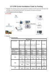
1.1.3 <strong>GV</strong>-<strong>AS</strong>100 Board Layout<br />
Figure 1-4<br />
1<br />
<strong>GV</strong>-<strong>AS</strong>100 <strong>Controller</strong><br />
5
1.2 Installation<br />
Please open <strong>GV</strong>-<strong>AS</strong>100 cabinet and wire the necessary connections to the terminal block as<br />
illustrated below.<br />
6<br />
Figure 1-5<br />
Pin Function Pin Function Pin Function<br />
1 12V Power 9 12V Power Supply 17 Door COM<br />
2 GND 10 GND 18 Door NC<br />
3<br />
RS-485 A+ for <strong>AS</strong>Box /<br />
<strong>AS</strong>Net or PC connection<br />
11 Sensor IN1 19 Door NO<br />
4<br />
5<br />
6<br />
RS-485 A-for <strong>AS</strong>Box /<br />
<strong>AS</strong>Net or PC connection<br />
RS-485 B+ for <strong>GV</strong>-<br />
Reader connection<br />
RS-485 B- for <strong>GV</strong>-<br />
Reader connection<br />
12 Button IN2<br />
13 Fire IN3<br />
14 IN COM<br />
7 Wiegand Data 0 15 Alarm COM<br />
8 Wiegand Data 1 16 Alarm NO
1.2.1 Connecting a Wiegand Reader<br />
1<br />
<strong>GV</strong>-<strong>AS</strong>100 <strong>Controller</strong><br />
<strong>GV</strong>-<strong>AS</strong>100 provides one Wiegand input for connection of the Wiegand reader ranging from<br />
26 to 64 bits. Through the <strong>GV</strong>-<strong>AS</strong>100 keypad, you can set the Wiegand reader as the entry<br />
or exit reader. To define the reader, see the <strong>AS</strong>100 Function option in 1.3.4 Setting<br />
Parameters.<br />
The table below shows the pin assignments of the Wiegand input on <strong>GV</strong>-<strong>AS</strong>100. Please<br />
consult the documentation of your Wiegand reader for wiring.<br />
Pin Function<br />
7 Wiegand Data 0<br />
8 Wiegand Data 1<br />
9 12V Power Supply<br />
10 GND<br />
1.2.2 Connecting Input Devices<br />
<strong>GV</strong>-<strong>AS</strong>100 supports 3 types of inputs:<br />
1. Sensor inputs, e.g. door status sensor<br />
2. Button inputs, e.g. door opener<br />
3. Fire Sensor inputs, e.g. fire detector<br />
All inputs are dry contact and can be configured as normally open (NO) or normally closed<br />
(NC) through the <strong>GV</strong>-<strong>AS</strong>100 keypad. The default value is NO. To change the input status,<br />
see the Set Contact Type option in 1.3.4 Setting Parameters.<br />
The table below shows the pin assignments of input connectors on <strong>GV</strong>-<strong>AS</strong>100.<br />
Pin Function<br />
11 Sensor IN1<br />
12 Button IN2<br />
13 Fire Sensor IN3<br />
14 IN COM<br />
7
1.2.3 Connecting Output Devices<br />
<strong>GV</strong>-<strong>AS</strong>100 supports 2 types of outputs:<br />
1. Alarm outputs, e.g. siren or bell<br />
2. Door outputs, e.g. electronic lock<br />
The table below shows the pin assignments of output connectors on <strong>GV</strong>-<strong>AS</strong>100.<br />
8<br />
Pin Function<br />
15 Alarm COM<br />
16 Alarm NO<br />
17 Door COM<br />
18 Door NC<br />
19 Door NO<br />
Check if your output device meets the following absolute maximum ratings before<br />
connecting it to the Door outputs.<br />
Breakdown Voltage 240V AC, 30V DC<br />
Continuous Load Current 5A (NO), 3A (NC)<br />
Note: Absolute Maximum Ratings are those values beyond which damage to <strong>GV</strong>-<br />
<strong>AS</strong>100 circuit board may occur. Continuous operation of <strong>GV</strong>-<strong>AS</strong>100 at the absolute<br />
rating level may affect <strong>GV</strong>-<strong>AS</strong>100 reliability.<br />
To connect an output device:<br />
The example below illustrates the connection of a locking device to <strong>GV</strong>-<strong>AS</strong>100. Connect the<br />
(+) point on the locking device to the Door COM on <strong>GV</strong>-<strong>AS</strong>100, connect the two (-) points of<br />
the locking device and the external power supply together, and connect the (+) point on the<br />
external power supply to the Door NO or Door NC on <strong>GV</strong>-<strong>AS</strong>100 based on the state of the<br />
locking device.<br />
Locking Device<br />
-<br />
+ -<br />
External<br />
Power Supply<br />
+<br />
Figure 1-6<br />
Door<br />
19 NO<br />
Door<br />
18 NC<br />
Door<br />
17 COM
1.2.4 Connecting the PC<br />
1<br />
<strong>GV</strong>-<strong>AS</strong>100 <strong>Controller</strong><br />
The computer running <strong>GV</strong>-<strong>AS</strong>Manager software can be used to monitor the access<br />
information and alarm messages from <strong>GV</strong>-<strong>AS</strong>100. The communication link between the<br />
computer and <strong>GV</strong>-<strong>AS</strong>100 can be either through RS-485 or network. For network connection,<br />
an optional <strong>GV</strong>-<strong>AS</strong>Box or <strong>GV</strong>-<strong>AS</strong>Net is required.<br />
IMPORTANT: To enable connecting to PC, Switch 1 must be turned on. See 1.2.4.C<br />
Switches.<br />
1.2.4.A RS-485 Connection<br />
The figure below illustrates the RS-485 connection to the computer. For this connection, a<br />
RS-485 to RS-232 converter between <strong>GV</strong>-<strong>AS</strong>100 and the computer is required. You can use<br />
<strong>GV</strong> accessories, such as <strong>GV</strong>-Hub, <strong>GV</strong>-COM and <strong>GV</strong>-NET/IO Card, as the RS-485/RS-232<br />
converter.<br />
Figure 1-7<br />
The table shows the pin assignments of related RS-485 connectors on <strong>GV</strong>-<strong>AS</strong>100.<br />
Pin Function<br />
3 RS-485 A+<br />
4 RS-485 A-<br />
Note: When connecting multiple <strong>GV</strong>-<strong>AS</strong>100 through RS-485 connection, you can use the<br />
keypad on <strong>GV</strong>-<strong>AS</strong>100 to program every unit’s ID. See 1.3.4 Setting Parameters.<br />
9
1.2.4.B Network Connection<br />
The figure below illustrates the network connection to the computer. For this connection, the<br />
optional product <strong>GV</strong>-<strong>AS</strong>Box or <strong>GV</strong>-<strong>AS</strong>Net is required.<br />
10<br />
Figure 1-8<br />
Connect two power wires and two RS-485 wires from <strong>GV</strong>-<strong>AS</strong>Box/<strong>GV</strong>-<strong>AS</strong>Net to <strong>GV</strong>-<strong>AS</strong>100.<br />
The table below shows the pin assignments of related connectors on <strong>GV</strong>-<strong>AS</strong>100.<br />
Pin Function Pin Function<br />
1 Power In 12V 3 RS-485 A+<br />
2 GND 4 RS-485 A-<br />
Also see 4.1.4.A Connecting <strong>GV</strong>-<strong>AS</strong>100/<strong>GV</strong>-<strong>AS</strong>110/<strong>GV</strong>-<strong>AS</strong>120.<br />
1.2.4.C Switches<br />
Switch 1: When Switch 1 is ON, <strong>GV</strong>-<strong>AS</strong>100 can connect to <strong>GV</strong>-<strong>AS</strong>Manager, <strong>GV</strong>-<strong>AS</strong>Box or<br />
<strong>GV</strong>-<strong>AS</strong>Net. When Switch 1 is OFF, the connection is unavailable. By default Switch 1 is set<br />
to ON.<br />
Switch 2: When the RS-485 connection between <strong>GV</strong>-<strong>AS</strong>100 and computer is longer than<br />
600 meters (1968.50 feet), the RS-485 signal may become weak. In this case, turn Switch 2<br />
ON to have a 120-Ohm resistor.<br />
Figure 1-9
1.2.5 Connecting the Power<br />
1<br />
<strong>GV</strong>-<strong>AS</strong>100 <strong>Controller</strong><br />
The supplied AC adaptor can be connected to any power source supplying from 100 to 240V.<br />
Using the supplied power cord and adaptor, connect <strong>GV</strong>-<strong>AS</strong>100 to the power.<br />
Note: Power should only be applied to the unit when all connections are completed and<br />
tested.<br />
1.2.6 Fitting the Battery<br />
<strong>GV</strong>-<strong>AS</strong>100 includes a 3V lithium battery, providing power to <strong>GV</strong>-<strong>AS</strong>100 settings and realtime<br />
clock circuitry. When the power in the battery becomes low, the message “Low Battery”<br />
will appear on <strong>GV</strong>-<strong>AS</strong>100 LCD. In this case, please replace the battery. All settings on <strong>GV</strong>-<br />
<strong>AS</strong>100 will disappear about 10 hours after the battery stops working, and <strong>GV</strong>-<strong>AS</strong>100 will be<br />
restored to default settings.<br />
Figure 1-10<br />
Note:<br />
1. Make sure the plastic insulation film under the battery is removed.<br />
2. It is recommended to replace the battery annually.<br />
11
1.3 Programming Mode<br />
After powering on <strong>GV</strong>-<strong>AS</strong>100, you must create a Master Card first. It is required to present<br />
the Master Card and enter its PIN code every time before programming <strong>GV</strong>-<strong>AS</strong>100.<br />
Note: The card complying with ISO 14443A standard for smart card technology can be<br />
formatted as a Master Card. Only one Master Card can be created.<br />
To create a Master Card:<br />
1. Power on the unit. The LCD displays Enter Master Card.<br />
2. Present a card to be the Master Card. The LCD displays Master PIN Code: 1234.<br />
3. Keep the default PIN code as 1234, and press #. The LCD displays Succeed.<br />
12<br />
Alternatively, you can press any four digits on the keypad to change the default value.<br />
The double confirmation of the new PIN code is required. After this, the LCD should<br />
display the message of success.<br />
After the Master Card is created, <strong>GV</strong>-<strong>AS</strong>100 will run a self test and display the message<br />
“Master Memory Test”. After it is finished, you can see the message of <strong>GV</strong>-<strong>AS</strong>100 online or<br />
offline followed by a date and time. Then you can start programming <strong>GV</strong>-<strong>AS</strong>100.<br />
The table below shows the codes to start various programming and display system<br />
information.<br />
Code Function<br />
*227 (*CAR) Accesses the Card Manager function.<br />
*276 (*ARM) Accesses Security Mode.<br />
*347 (*DIS) Displays system information.<br />
*738 (*SET) Accesses parameter settings.<br />
*737 (*RES) Restores <strong>GV</strong>-<strong>AS</strong>100 to factory defaults.<br />
*837 (*TES) Tests numeral keys to see if they can be displayed properly.
Before programming <strong>GV</strong>-<strong>AS</strong>100, you also need to know the following keys.<br />
Key Function<br />
* Used to cancel the selection, or go back to the previous page.<br />
1<br />
<strong>GV</strong>-<strong>AS</strong>100 <strong>Controller</strong><br />
# Used to save the data that was modified or programmed in the<br />
system and quit.<br />
0 Used to go to the next page.<br />
13
1.3.1 Quick Reference of Programming Table<br />
Card Manger<br />
Add New Card 1) N, 2) A, 3) B, 4) S<br />
Del Card Data<br />
Reset Card’s APB<br />
Display System<br />
Door’s Auth Mode<br />
Door’s Event<br />
<strong>AS</strong>Box Comm. State<br />
Memory’s State<br />
ID & IP Address<br />
Display Version<br />
Set Parameter<br />
Set Local Time<br />
Set <strong>AS</strong>100 ID<br />
Set Auth. Mode<br />
Auth. Schedule<br />
Fixed Card Mode<br />
Fixed Card + PIN<br />
Fixed Card Common<br />
Local Unlock Mode<br />
Local Lock Mode<br />
<strong>AS</strong>100 Function<br />
<strong>GV</strong>-<strong>AS</strong>Box<br />
Control Type Door Entry Type Anti-Passback<br />
Door Exit Type Anti-Passback<br />
Parking Entry Type Anti-Passback<br />
Parking Exit Type Anti-Passback<br />
Elevator Control<br />
Master PIN Change<br />
Local Rest Time<br />
Set Held Open Time<br />
Set Alarm Event<br />
Held Open Alarm<br />
Force Open Alarm<br />
Fire Alarm<br />
Tamper Alarm<br />
Access Denied<br />
Set Fire Action<br />
Unlock Door/Gate<br />
Lock Door/Gate<br />
Unchanged<br />
Set Contact Type<br />
Door/Car Sensor<br />
Door/Gate Button<br />
Fire Sensor<br />
14
1.3.2 Accessing the Card Manager<br />
1<br />
<strong>GV</strong>-<strong>AS</strong>100 <strong>Controller</strong><br />
The Card Manager option is used to add cards, delete cards and reset the card’s APB<br />
function.<br />
Note:<br />
1. <strong>GV</strong>-<strong>AS</strong>Manager cannot manage the cards enrolled on <strong>GV</strong>-<strong>AS</strong>100, since the card data will<br />
not be transmitted to <strong>GV</strong>-<strong>AS</strong>Manager.<br />
2. The cards added through <strong>GV</strong>-<strong>AS</strong>Manager cannot be deleted on <strong>GV</strong>-<strong>AS</strong>100.<br />
1.3.2.A Adding a Card<br />
Up to 1,000 cards can be enrolled on <strong>GV</strong>-<strong>AS</strong>100 directly without needing additional software.<br />
When working with <strong>GV</strong>-<strong>AS</strong>Manager software, <strong>GV</strong>-<strong>AS</strong>100 can support up to 40,000 cards.<br />
1. Press the code *227 (*CAR).<br />
2. Present the Master Card and enter its PIN code. The LCD displays Add New Card.<br />
3. Press #. The LCD displays Enter New Card.<br />
4. To add a card, you can either press the card number or present the card to the unit. The<br />
LCD displays the card number and these options: 1)N 2)A 3)B 4)S.<br />
N stands for a normal card; A stands for a two-person A card; B stands for a two-person<br />
B card; S stands for a security card.<br />
5. Select a card type, and enter and confirm a PIN code for the new card.<br />
The LCD displays Store New Card, 1. Yes? 2. No?.<br />
6. Press 1 to save and exit.<br />
1.3.2.B Deleting a Card<br />
1. Press the code *227 (*CAR).<br />
2. Present the Master Card and enter its PIN code. The LCD displays Add New Card.<br />
3. Press 0. The LCD displays Del Card Data.<br />
4. Press #. The LCD displays Enter Del Card.<br />
5. You can either press the card number or present the card to the unit.<br />
The LCD displays: Delete, 1. Yes? 2. No?.<br />
6. Press 1 to save and exit.<br />
15
1.3.2.C Resetting the APB Function<br />
You can reset the anti-passback (APB) function of a card to allow a user to re-access the<br />
entry or exit reader.<br />
1. Press the code *227 (*CAR).<br />
2. Present the Master Card and enter its PIN code. The LCD displays Add New Card.<br />
3. Press 0 several times. The LCD displays Reset Card’s APB.<br />
4. Press #. The LCD displays Enter Card.<br />
5. You can either press the card number or present the card to the unit.<br />
16<br />
The LCD displays: Reset, 1. Yes? 2. No?.<br />
6. Press 1 to save and exit.<br />
1.3.3 Accessing the Security Mode<br />
The security mode is used to arm <strong>GV</strong>-<strong>AS</strong>100. In the arm mode, no cards can be granted<br />
access and no one can program the unit. Only the security card that is associated with a PIN<br />
code can be used to disarm the unit.<br />
1.3.3.A Enabling the Security Mode<br />
Before you can access the security mode, you need to create a security card first.<br />
1. To create a security card, follow the steps 1 to 4 in 1.3.2.A Adding a Card, select 4)S as<br />
card type and create a PIN code for the security card.<br />
2. To access security mode, press the code *276 (*ARM).<br />
The LCD displays Start Arm? Enter PIN Code.<br />
3. Press the PIN code of the security card.<br />
The LCD displays Start Arm? Enter Security Card.<br />
4. Present the security card. The security mode is enabled.<br />
1.3.3.B Disabling the Security Mode<br />
To disable the security mode, press any key, enter the PIN code of the security card and<br />
present the security card.
1.3.4 Setting Parameters<br />
You can define the parameters of some features on <strong>GV</strong>-<strong>AS</strong>100.<br />
1<br />
<strong>GV</strong>-<strong>AS</strong>100 <strong>Controller</strong><br />
IMPORTANT: Once connecting to <strong>GV</strong>-<strong>AS</strong>100, <strong>GV</strong>-<strong>AS</strong>Manager will load its parameters to<br />
<strong>GV</strong>-<strong>AS</strong>100. That means some of parameters you set up here may be overwritten by <strong>GV</strong>-<br />
<strong>AS</strong>Manager later.<br />
1. Press the code *738 (*SET).<br />
2. Present the Master Card and enter its PIN code. The LCD displays Set Local Time.<br />
3. Press 0 to change the options. Press # to select the option for further programming.<br />
Option Function<br />
Set Local Time Sets the time, time zone and enables daylight saving.<br />
Set <strong>AS</strong>100 ID Sets the ID of <strong>GV</strong>-A100 from 1 to 255.<br />
Set Auth. Mode Sets an authentication mode for the door/gate.<br />
� Auth. Schedule: Follows the authentication schedule set on<br />
<strong>GV</strong>-<strong>AS</strong>Manager.<br />
� Fixed Card Mode: Grants access after the card is presented.<br />
Ignores the authentication schedule of <strong>GV</strong>-<strong>AS</strong>Manager.<br />
� Fixed Card + PIN: Grants access after the user presents the<br />
card and then enters the card’s PIN code. Ignores the<br />
authentication schedule of <strong>GV</strong>-<strong>AS</strong>Manager.<br />
� Fixed Card/Common: Grants access after the user presents<br />
the card or enters the door’s password. Enter the door’s<br />
password after the LCD displays Common Password. Ignores<br />
the authentication schedule of <strong>GV</strong>-<strong>AS</strong>Manager.<br />
� Local Unlock Mode: Remains open. The held-open state<br />
cannot be cleared through <strong>GV</strong>-<strong>AS</strong>Manager.<br />
� Local Lock Mode: Remains locked. The locked state cannot<br />
be cleared through <strong>GV</strong>-<strong>AS</strong>Manager.<br />
17
<strong>AS</strong>100 Function � <strong>GV</strong>-<strong>AS</strong>Box: Enables or disables the connection to <strong>GV</strong>-<strong>AS</strong>Box /<br />
<strong>GV</strong>-<strong>AS</strong>Net.<br />
18<br />
� Control Type:<br />
� Door Entry Type: Sets <strong>GV</strong>-<strong>AS</strong>100 as entry reader of a<br />
door. The Wiegand reader connected will be set as exit<br />
reader.<br />
� Door Exit Type: Sets <strong>GV</strong>-<strong>AS</strong>100 as exit reader of a door.<br />
The Wiegand reader connected will be set as entry reader.<br />
� Parking Entry Type: Sets <strong>GV</strong>-<strong>AS</strong>100 as entry reader of a<br />
parking gate.<br />
� Parking Exit Type: Sets <strong>GV</strong>-<strong>AS</strong>100 as exit reader of a<br />
parking gate.<br />
� Elevator Type: <strong>GV</strong>-<strong>AS</strong>100 reader is installed in the<br />
elevator for access control.<br />
� Anti-Passback: Enables or disables the Anti-Passback<br />
function.<br />
Master PIN Change Changes the PIN code of the Master Card.<br />
Local Rest Time Sets the time (1 to 255 sec.) that a door/gate remains open after<br />
which the door will automatically be locked.<br />
Set Held Open<br />
Time<br />
Sets the time (5 to 9999 sec.) that a door/gate can be held open<br />
before an alarm is generated.<br />
Set Alarm Event Enables or disables the alarm settings.<br />
Set Fire Action Locks or unlocks the door/gate, or remains the current state when a<br />
fire condition occurs.<br />
Set Contact Type Sets the inputs to be normally open (NO) or normally closed (NC).<br />
Note: The Parking Entry Type and Parking Exit Type only work when the sensor input of<br />
Car Detection is activated. When the card is present but the sensor inputs are not activated,<br />
the message “No Car In Zone” will appear in the <strong>GV</strong>-<strong>AS</strong>100’s LCD.
1.3.5 Displaying System Information<br />
To display system information, press the code *347 (*DIS).<br />
Option Function<br />
Door’s Auth. Mode Displays the authentication mode of the door.<br />
Door’s Event Displays what kind of event happened at the door.<br />
1<br />
<strong>GV</strong>-<strong>AS</strong>100 <strong>Controller</strong><br />
<strong>AS</strong>Box Comm. State Displays the connection status with <strong>GV</strong>-<strong>AS</strong>Box/<strong>GV</strong>-<strong>AS</strong>Net.<br />
� <strong>User</strong> Disenable: The connection to <strong>GV</strong>-<strong>AS</strong>Box/<strong>GV</strong>-<strong>AS</strong>Net<br />
is not enabled.<br />
� Comm. Fail: The connection to <strong>GV</strong>-<strong>AS</strong>Box/<strong>GV</strong>-<strong>AS</strong>Net<br />
failed.<br />
� Comm. Normal: The connection to <strong>GV</strong>-<strong>AS</strong>Box/<strong>GV</strong>-<strong>AS</strong>Net<br />
succeeded.<br />
Memory’s State Displays the memory usage of <strong>GV</strong>-<strong>AS</strong>100.<br />
� Capacity: Displays the total number of events that can be<br />
recorded on <strong>GV</strong>-<strong>AS</strong>100. The maximum number is 65536.<br />
<strong>GV</strong>-<strong>AS</strong>100 will overwrite the oldest events when the limit is<br />
reached. When <strong>GV</strong>-<strong>AS</strong>100 is connected to <strong>GV</strong>-<strong>AS</strong>Manager,<br />
the event data will be uploaded to the server and the buffer<br />
of <strong>GV</strong>-<strong>AS</strong>100 will be cleared.<br />
� Stored: Displays the number of events that has been<br />
recorded.<br />
ID & IP Address Displays the ID and IP address of <strong>GV</strong>-<strong>AS</strong>100.<br />
Display Version Displays the firmware version of <strong>GV</strong>-<strong>AS</strong>100.<br />
19
1.3.6 Restoring Factory Defaults<br />
The restore function is used to clear all configured options and cards from <strong>GV</strong>-<strong>AS</strong>100<br />
memory and bring back the unit to factory defaults.<br />
IMPORTANT: Restoring default settings will delete all cards enrolled on <strong>GV</strong>-<strong>AS</strong>100.<br />
1. Press the code *737 (*RES).<br />
2. Present the Master Card and enter PIN Code.<br />
20<br />
The LCD displays Default Setting 1. Yes? 2. No?.<br />
3. Press 1. The LCD displays Default Setting Memory Test…<br />
4. When the unit returns to factory defaults, the LCD displays Enter Master Card.
1.4 Web-Based Configurations<br />
1<br />
<strong>GV</strong>-<strong>AS</strong>100 <strong>Controller</strong><br />
Through <strong>GV</strong>-<strong>AS</strong>Box or <strong>GV</strong>-<strong>AS</strong>Net, <strong>GV</strong>-<strong>AS</strong>100 can communicate with <strong>GV</strong>-<strong>AS</strong>Manager over<br />
the network. Using <strong>GV</strong>-<strong>AS</strong>Box or <strong>GV</strong>-<strong>AS</strong>Net, you can also access the Web interface of <strong>GV</strong>-<br />
<strong>AS</strong>100.<br />
Refer to Chapter 5 Optional Devices to see how to connect a <strong>GV</strong>-<strong>AS</strong>Box or <strong>GV</strong>-<strong>AS</strong>Net and<br />
how to access the Web interface of <strong>GV</strong>-<strong>AS</strong>100.<br />
21
1.5 <strong>GV</strong>-<strong>AS</strong>100 Specifications<br />
CPU 8-bit RISC microprocessor<br />
Number of <strong>User</strong> Cards<br />
22<br />
1,000 / 40,000 cards (standalone / networked or RS-<br />
485 mode)<br />
Event Buffer 65,536 events and log data<br />
Power 100 ~ 240V AC, 50 ~ 60Hz<br />
Wiegand Interface<br />
Communication Protocol RS-485<br />
Digital I/O<br />
1 Wiegand interface, 26 ~ 64 bit format<br />
12V DC Power Supply, 200mA<br />
Input 3 inputs, dry contact, NO / NC<br />
Output 2 outputs<br />
Operating Temperature 0 ~ 65°C / 32 ~ 149°F<br />
Operating Humidity 10% ~ 90% RH (non-condensing)<br />
Dimensions of <strong>GV</strong>-<strong>AS</strong>100 Board<br />
(W X H X D)<br />
Weight 250 g / 0.55 Ib<br />
96 x 137 x 27 mm / 13.78 x 5.39 x 1.06 in<br />
Certification IP54, CE, FCC, RoHS
2. <strong>GV</strong>-<strong>AS</strong>110 <strong>Controller</strong>
2.1 Introduction<br />
Working as a standalone solution, <strong>GV</strong>-<strong>AS</strong>110 is a card reader and also a single door<br />
controller. It is possible to add one more card reader to <strong>GV</strong>-<strong>AS</strong>110 for entry and exit<br />
applications. <strong>GV</strong>-<strong>AS</strong>110 has the capability to store up to one thousand cards. When <strong>GV</strong>-<br />
<strong>AS</strong>110 is being used as a standalone unit, the programming is either done on the keypad or<br />
from the software <strong>GV</strong>-<strong>AS</strong>Manager through the RS-485 connection.<br />
<strong>GV</strong>-<strong>AS</strong>110 is suitable not only for any normal door control but also for parking gate and<br />
elevator control. <strong>GV</strong>-<strong>AS</strong>110 is an economic solution for access control.<br />
24<br />
Figure 2-1<br />
1 2 3<br />
4 5 6<br />
7 8 9<br />
* 0 #
2<br />
<strong>GV</strong>-<strong>AS</strong>110 <strong>Controller</strong><br />
<strong>GV</strong>-<strong>AS</strong>110 can make network connection to <strong>GV</strong>-<strong>AS</strong>Manager using the optional <strong>GV</strong>-<strong>AS</strong>Box<br />
or <strong>GV</strong>-<strong>AS</strong>Net. With <strong>GV</strong>-<strong>AS</strong>Box, two-door control is also possible as illustrated below.<br />
Figure 2-2 Through <strong>GV</strong>-<strong>AS</strong>Box<br />
1 2 3<br />
4 5 6<br />
7 8 9<br />
* 0 #<br />
Figure 2-3 Through <strong>GV</strong>-<strong>AS</strong>Net<br />
25
2.1.1 Main Features<br />
• 1,000 / 40,000 cards (standalone / networked or RS-485 mode)<br />
• Easy programming from keypad<br />
• Anti-Passback (APB) support<br />
• Built-in 3 digital inputs and 2 relay outputs<br />
• 1 Wiegand output (26 ~ 64 bits) for extra reader programming<br />
• 1 door expandable to 2 doors with optional <strong>GV</strong>-<strong>AS</strong>Box<br />
• Built-in tampering alarm<br />
2.1.2 Packing List<br />
• <strong>GV</strong>-<strong>AS</strong>110<br />
• Power Adaptor 12V DC<br />
• Power Cable<br />
• Enroll Card<br />
• Delete Card<br />
• <strong>GV</strong>-<strong>AS</strong>Manager Software CD<br />
2.2 Installation<br />
The wire assignment of the <strong>GV</strong>-<strong>AS</strong>110 cable data are illustrated below.<br />
26<br />
Front View Rear View<br />
Figure 2-4
Wire color Definition<br />
Red 12V<br />
Black GND<br />
Green Wiegand Data 0<br />
White Wiegand Date 1<br />
Blue RS485+<br />
Light Blue RS485-<br />
Yellow Door Sensor IN1<br />
Orange Button IN2<br />
LRed Fire Sensor IN3<br />
Brown IN COM (GND)<br />
Purple Alarm COM<br />
Gray Alarm NO<br />
Brown White Door COM<br />
Black White Door NC<br />
Light Green Door NO<br />
2<br />
<strong>GV</strong>-<strong>AS</strong>110 <strong>Controller</strong><br />
27
2.2.1 Connecting a Wiegand Reader<br />
<strong>GV</strong>-<strong>AS</strong>110 provides one Wiegand input for connection to the Wiegand reader ranging from<br />
26 to 64 bits. Through the <strong>GV</strong>-<strong>AS</strong>110 keypad, you can set the Wiegand reader as the entry<br />
or exit reader. To define the reader, see the Door/Gate Function option in 2.3.2<br />
Programming the <strong>GV</strong>-<strong>AS</strong>110.<br />
The table below shows the wire assignments of the Wiegand input on <strong>GV</strong>-<strong>AS</strong>110. Please<br />
consult the documentation of your Wiegand reader for wiring. You will need to set up a<br />
separate power source to power the Wiegand reader.<br />
Wire color Definition<br />
Green Wiegand Data 0<br />
White Wiegand Date 1<br />
2.2.2 Connecting Input Devices<br />
<strong>GV</strong>-<strong>AS</strong>110 supports 3 types of inputs:<br />
1. Sensor inputs, e.g. door status sensor<br />
2. Button inputs, e.g. door opener<br />
3. Fire Sensor inputs, e.g. fire detector<br />
All inputs are dry contact and can be configured as normally open (NO) or normally closed<br />
(NC) through the <strong>GV</strong>-<strong>AS</strong>110 keypad. The default value is NO. To change the input status,<br />
see the Select Input Contact Type option in 2.3.2 Programming the <strong>GV</strong>-<strong>AS</strong>110.<br />
The table below shows the wire assignments of input connectors on <strong>GV</strong>-<strong>AS</strong>110.<br />
Wire color Definition<br />
Yellow Door Sensor IN1<br />
Orange Button IN2<br />
LRed Fire Sensor IN3<br />
Brown IN COM (GND)<br />
28
2.2.3 Connecting Output Devices<br />
<strong>GV</strong>-<strong>AS</strong>110 supports 2 types of outputs:<br />
1. Alarm outputs, e.g. siren or bell<br />
2. Door outputs, e.g. electronic lock<br />
The table below shows the wire assignments of output connectors on <strong>GV</strong>-<strong>AS</strong>110.<br />
Wire color Definition<br />
Purple Alarm COM<br />
Gray Alarm NO<br />
Brown & White Door COM<br />
Black & White Door NC<br />
Light green Door NO<br />
Check if your output device meets the following absolute maximum ratings before<br />
connecting it to the Door outputs.<br />
Breakdown Voltage 250V AC, 220V DC<br />
Continuous Load Current 1A (30V DC), 0.3A (125V AC)<br />
2<br />
<strong>GV</strong>-<strong>AS</strong>110 <strong>Controller</strong><br />
Note: Absolute Maximum Ratings are those values beyond which damage to <strong>GV</strong>-<br />
<strong>AS</strong>110 circuit board may occur. Continuous operation of <strong>GV</strong>-<strong>AS</strong>110 at the absolute<br />
rating level may affect <strong>GV</strong>-<strong>AS</strong>110’s reliability.<br />
To connect an output device:<br />
The example below illustrates the connection of a locking device to <strong>GV</strong>-<strong>AS</strong>110. Connect the<br />
(+) point on the locking device to the Door COM wire on <strong>GV</strong>-<strong>AS</strong>110, connect the two (-)<br />
points of the locking device and the external power supply together, and connect the (+)<br />
point on the external power supply to the Door NO or Door NC wire on <strong>GV</strong>-<strong>AS</strong>110 based on<br />
the state of the locking device.<br />
Locking Device<br />
+ -<br />
External<br />
Power Supply<br />
- +<br />
Light Green, Door NO<br />
Black & White, Door NC<br />
Brown & White, Door COM<br />
Figure 2-5<br />
1 2 3<br />
4 5 6<br />
7 8 9<br />
* 0 #<br />
29
2.2.4 Connecting to the PC<br />
The computer running <strong>GV</strong>-<strong>AS</strong>Manager software can be used to monitor the access<br />
information and alarm messages from <strong>GV</strong>-<strong>AS</strong>110. The communication link between the<br />
computer and <strong>GV</strong>-<strong>AS</strong>110 can be either through RS-485 or network. For RS-485 connection,<br />
a RS-485 to RS-232 converter is required. For network connection, an optional <strong>GV</strong>-<strong>AS</strong>Box<br />
or <strong>GV</strong>-<strong>AS</strong>Net is required.<br />
2.2.4.A RS-485 Connection<br />
The figure below illustrates the RS-485 connection to the computer. For this connection, a<br />
RS-485 to RS-232 converter between <strong>GV</strong>-<strong>AS</strong>110 and the computer is required. You can use<br />
<strong>GV</strong> accessories, such as <strong>GV</strong>-Hub, <strong>GV</strong>-COM and <strong>GV</strong>-NET/IO Card, as the RS-485/RS-232<br />
converter.<br />
30<br />
1 2 3<br />
4 5 6<br />
7 8 9<br />
* 0 #<br />
Figure 2-6<br />
The table shows the wire assignments of RS-485 connection on <strong>GV</strong>-<strong>AS</strong>110.<br />
Wire color Definition<br />
Blue RS485 A+<br />
Light Blue RS485 A-<br />
Note: When connecting multiple <strong>GV</strong>-<strong>AS</strong>110 through RS-485 connection, you can use the<br />
keypad on <strong>GV</strong>-<strong>AS</strong>110 to program every unit’s ID. See 2.3.2 Programming the <strong>GV</strong>-<strong>AS</strong>110.
2.2.4.B Network Connection<br />
2<br />
<strong>GV</strong>-<strong>AS</strong>110 <strong>Controller</strong><br />
The figure below illustrates the network connection to the computer. For this connection, a<br />
<strong>GV</strong>-<strong>AS</strong>Box or <strong>GV</strong>-<strong>AS</strong>Net is required.<br />
1 2 3<br />
4 5 6<br />
7 8 9<br />
* 0 #<br />
Figure 2-7<br />
Connect two power wires and two RS-485 wires from <strong>GV</strong>-<strong>AS</strong>110 to <strong>GV</strong>-<strong>AS</strong>Box/<strong>GV</strong>-<strong>AS</strong>Net.<br />
The table below shows the wire assignments of RS-485 connection on <strong>GV</strong>-<strong>AS</strong>110.<br />
Wire color Definition<br />
Red 12V<br />
Black GND<br />
Blue RS485 A+<br />
Light Blue RS485 A-<br />
See 4.1.5.A Connecting <strong>GV</strong>-<strong>AS</strong>100/<strong>GV</strong>-<strong>AS</strong>110/<strong>GV</strong>-<strong>AS</strong>120 or 4.2.4A Connecting <strong>GV</strong>-<br />
<strong>AS</strong>100/<strong>GV</strong>-<strong>AS</strong>110/<strong>GV</strong>-<strong>AS</strong>120 to see how to connect to <strong>GV</strong>-<strong>AS</strong>Box or <strong>GV</strong>-<strong>AS</strong>Net.<br />
2.2.5 Connecting the Power<br />
The supplied AC adaptor can be connected to any power source supplying from 100 to 240V.<br />
Connect 12V and GND wires to the supplied power adapter and then connect the power<br />
adapter to a power source. The table below shows the pin assignments of the power<br />
connectors on <strong>GV</strong>-<strong>AS</strong>110.<br />
Wire color Definition<br />
Red 12V<br />
Black GND<br />
Note: Power should only be applied to the unit when all connections are completed and<br />
tested.<br />
31
2.3 Programming Mode<br />
After powering on <strong>GV</strong>-<strong>AS</strong>110, you must create two cards first, an Enroll Card and a Delete<br />
Card. The Enroll Card is used for adding new cards and the Delete Card is used for deleting<br />
cards. Either card will allow you to program the various configurations on <strong>GV</strong>-<strong>AS</strong>110.<br />
Note: The card complying with ISO 14443A standard for smart card technology can be<br />
formatted as an Enroll Card or Delete Card.<br />
To create the Enroll Card and the Delete Card:<br />
1. Power on the unit. The LED flashes blue.<br />
2. Present a card to be the Enroll Card.<br />
3. Present a card to be the Delete Card.<br />
4. The <strong>GV</strong>-<strong>AS</strong>110 will automatically load default, and the LED will flash blue and yellow.<br />
After 1 to 2 minutes, the LED should be a constant blue light to indicate READY.<br />
2.3.1 Adding and Deleting Cards<br />
Using the two cards, you can add new cards to <strong>GV</strong>-<strong>AS</strong>110 and delete existing cards on <strong>GV</strong>-<br />
<strong>AS</strong>110.<br />
Note:<br />
1. <strong>GV</strong>-<strong>AS</strong>Manager cannot manage the cards enrolled on <strong>GV</strong>-<strong>AS</strong>110, since the card data<br />
will not be transmitted to <strong>GV</strong>-<strong>AS</strong>Manager.<br />
2. The cards added through <strong>GV</strong>-<strong>AS</strong>Manager cannot be deleted on <strong>GV</strong>-<strong>AS</strong>110.<br />
32
2.3.1.A Adding a Card<br />
2<br />
<strong>GV</strong>-<strong>AS</strong>110 <strong>Controller</strong><br />
Up to 1,000 cards can be enrolled on <strong>GV</strong>-<strong>AS</strong>110 directly without needing additional software.<br />
When working with <strong>GV</strong>-<strong>AS</strong>Manager software, <strong>GV</strong>-<strong>AS</strong>110 can support up to 40,000 cards.<br />
1. Present the Enroll Card.<br />
2. Enter a 4-digit PIN code for the new card, reenter the same 4-digit PIN code and then<br />
enter the command code for a desired type of card listed below. The LED will blink green<br />
and red for about 10 seconds. You must finish entering the PIN code twice and the card<br />
command code within the 10 seconds.<br />
Code Types of Cards Description<br />
0 Normal Card The door unlocks after a card is presented. Normal<br />
Cards will not be granted access when Two Person<br />
Entrance/Exit or Security Mode is enabled.<br />
1 Two-person A Card In the Two Person Entrance/Exit mode, the door<br />
unlocks only when two-person B card is also<br />
presented together.<br />
2 Two-person B Card In the Two Person Entrance/Exit mode, the door<br />
unlocks only when two-person A card is also<br />
presented together.<br />
3 Security Card The Security Card is used for launching the Security<br />
Mode, in which no cards can be granted access and<br />
no one can program the unit. Only the Security Card<br />
will be able to disable the Security Mode.<br />
3. Present the card you want to add to the <strong>GV</strong>-<strong>AS</strong>110.<br />
4. The <strong>GV</strong>-<strong>AS</strong>110 will produce a long beep if the card has been added successfully and<br />
three short beeps if the adding procedure has failed.<br />
If you do not want to customize a password, you can simply present the Enroll Card and<br />
then present the card you would like to add. The default password will be 1234 and the card<br />
will automatically be set to a Normal Card.<br />
2.3.1.B Deleting a Card<br />
1. Present the Delete Card.<br />
2. Present the card you want to delete.<br />
3. The <strong>GV</strong>-<strong>AS</strong>110 will produce a long beep if the card has been deleted successfully and<br />
three short beeps if the deleting procedure has failed.<br />
33
2.3.2 Programming the <strong>GV</strong>-<strong>AS</strong>110<br />
The command codes used to program various functions on <strong>GV</strong>-<strong>AS</strong>110 are listed below. All<br />
command codes will start with an asterisk * to clear all previous commands and end with a<br />
number sign # to send the command. After typing the command code, present the Enroll<br />
Card or the Delete Card.<br />
IMPORTANT: Once connecting to <strong>GV</strong>-<strong>AS</strong>110, <strong>GV</strong>-<strong>AS</strong>Manager will load its parameters to<br />
<strong>GV</strong>-<strong>AS</strong>110. That means some of settings you program here may be overwritten by <strong>GV</strong>-<br />
<strong>AS</strong>Manager later.<br />
Function Command Code Description<br />
Set Password<br />
Lock Reset<br />
Time<br />
Held Open<br />
Time<br />
Set Fire Action<br />
Local Anti-<br />
Passback<br />
34<br />
*779_ _ _ _ _ _ _ _ #<br />
4-8 digits<br />
*578_ _ _ #<br />
1-255 seconds<br />
*468_ _ _ _ #<br />
5-9999 seconds<br />
*732_#<br />
Unchanged�0<br />
Unlock Door�1<br />
Lock Door�2<br />
*527_#<br />
0�Disable<br />
1�Enable<br />
You can set a password to open the door using<br />
this password. The Authentication Mode must<br />
be set to Fixed Card/Common mode. Refer to<br />
the Set Authentication Mode function below.<br />
For example, to set the door’s password as<br />
12345, press *77912345# on the keypad.<br />
Sets a time that the door/gate will remain open<br />
after which the door will automatically be<br />
locked.<br />
For example, to set the lock reset time to be<br />
120 seconds, press *578120#<br />
Sets the time that a door/gate can be held open<br />
before an alarm is generated. If the number of<br />
seconds is less than 4 digits, add zeros in front<br />
of the number to make it 4 digits.<br />
For example, to set the held open time to be<br />
180 seconds, enter *4680180#<br />
This function locks or unlocks the door/gate, or<br />
maintains the current status when a fire<br />
emergency occurs.<br />
For example, to unlock door during a fire<br />
emergency, press *7321#<br />
Local Anti-passback prevents card sharing by<br />
not allowing a card to go through an entry twice<br />
before first exiting.<br />
For example, to enable Local Anti-passback,<br />
press *5271#
Set Alarm<br />
Event<br />
Door/Gate<br />
Function<br />
Set<br />
Authentication<br />
Mode<br />
*723_ _ _ _#<br />
Held Open � 0<br />
Forced Open � 1<br />
Tamper � 2<br />
Fire Alarm � 3<br />
Access Denied � 4<br />
Alarm Time � 1-10 sec<br />
*343_#<br />
Door Entry Type�0<br />
Parking Entry Type�1<br />
Door Exit Type�2<br />
Parking Exit Type�3<br />
Elevator Type�4<br />
*526_#<br />
Schedule Mode�0<br />
Fixed Card Mode�1<br />
Local Lock Mode�2<br />
Local Unlock Mode�3<br />
Fixed Card + PIN�4<br />
Fixed Card/Common�5<br />
2<br />
<strong>GV</strong>-<strong>AS</strong>110 <strong>Controller</strong><br />
For the first blank digit, enter a number from<br />
options 0 to 4. For the second blank digit, type<br />
1 to enable the option and 0 to disable the<br />
option. For the third and fourth blank digits, type<br />
the number of seconds the alarm will sound.<br />
For example, to enable the fire alarm for 3<br />
seconds, press *7233103#<br />
� Door Entry Type: Sets <strong>GV</strong>-<strong>AS</strong>110 as entry<br />
reader of a door. The Wiegand reader<br />
connected will be set as exit reader.<br />
� Parking Entry Type: Sets <strong>GV</strong>-<strong>AS</strong>110 as<br />
entry reader of a parking gate.<br />
� Door Exit Type: Sets <strong>GV</strong>-<strong>AS</strong>110 as exit<br />
reader of a door. The Wiegand reader<br />
connected will be set as entry reader.<br />
� Parking Exit Type: Sets <strong>GV</strong>-<strong>AS</strong>110 as exit<br />
reader of a parking gate.<br />
� Elevator Type: <strong>GV</strong>-<strong>AS</strong>110 reader is<br />
installed in the elevator for access control.<br />
For example, to set the <strong>GV</strong>-<strong>AS</strong>110 as an exit<br />
reader of a door, press *3432#<br />
� Schedule Mode: Follows the<br />
authentication schedule set on <strong>GV</strong>-<br />
<strong>AS</strong>Manager.<br />
� Fixed Card Mode: Grants access after the<br />
card is presented. Ignores the<br />
authentication schedule of <strong>GV</strong>-<strong>AS</strong>Manager.<br />
� Local Lock Mode: Remains locked. The<br />
locked state cannot be cleared through <strong>GV</strong>-<br />
<strong>AS</strong>Manager.<br />
� Local Unlock Mode: Remains open. The<br />
held-open state cannot be cleared through<br />
<strong>GV</strong>-<strong>AS</strong>Manager.<br />
� Fixed Card + PIN: Grants access after the<br />
user presents the card and then enters the<br />
card’s PIN code. Ignores the authentication<br />
schedule of <strong>GV</strong>-<strong>AS</strong>Manager.<br />
� Fixed Card/Common: Grants access after<br />
card is presented or after the door’s<br />
password is entered. Ignores the<br />
authentication schedule of <strong>GV</strong>-<strong>AS</strong>Manager.<br />
35
Open door<br />
with card<br />
number and<br />
PIN code<br />
Set ID<br />
Security Mode<br />
Two Person<br />
Entrance<br />
Two Person<br />
Exit<br />
Select Input<br />
Contact Type<br />
36<br />
*_ _ _ _ _ _ _ _(_ _ _ _)#<br />
Enter the 8-digit card<br />
number and enter its 4-<br />
digit PIN code.<br />
*743_ _ _#<br />
Enter an ID number<br />
between 0 and 255.<br />
*276_ _ _ _#<br />
4 digits PIN code of the<br />
security card.<br />
*873_#<br />
Disable�0<br />
Enable�1<br />
*879_#<br />
Disable�0<br />
Enable�1<br />
*426_ _ _#<br />
NO�1<br />
NC�0<br />
Load Default *362#<br />
For example, to enable the Fixed Card + PIN<br />
mode, press *5264#.<br />
To open the door without presenting a card,<br />
enter the 8-digit card number on the back of the<br />
individual card and its 4-digit PIN code.<br />
Set an ID number for <strong>GV</strong>-<strong>AS</strong>110 to a number<br />
between 0 and 255.<br />
For example, to set the ID number to be 3,<br />
press *743003#<br />
In the Security Mode, no cards can be granted<br />
access and no one can program the unit. Only<br />
the Security Card can disable the Security<br />
Mode.<br />
To enable the Security Mode, press *276,<br />
enter the PIN code of the Security Card and<br />
press #. Present the Security Card.<br />
To disable the Security Mode, simply press the<br />
PIN code of the Security Card and present the<br />
Security Card.<br />
When Two Person Entrance mode is enabled,<br />
both Two Person A Card and Two Person B<br />
Card must be presented to unlock the entrance.<br />
To enable Two Person Entrance, press *<br />
8731#<br />
When Two Person Exit mode is enabled, both<br />
Two Person A Card and Two Person B Card<br />
must be presented to unlock the exit.<br />
To enable Two Person Exit, press *8791#<br />
Specify the input contact type of the door<br />
sensor in the first blank digit, button in the<br />
second blank digit and fire sensor in the third<br />
blank digit. The default value is normally<br />
opened (NO).<br />
For example, to set the input contact type for<br />
door sensor to be normally open (NO), button to<br />
be normally closed (NC), and fire sensor to be<br />
normally open (NO), press *426101#.<br />
To restore <strong>GV</strong>-<strong>AS</strong>110 to factory default, press<br />
*362#. All configured settings will be cleared<br />
and all cards will be deleted from <strong>GV</strong>-<strong>AS</strong>110.<br />
Note: The Parking Entry Type and Parking Exit Type only work when the sensor input of<br />
Car Detection is activated.
2.4 Web-Based Configurations<br />
2<br />
<strong>GV</strong>-<strong>AS</strong>110 <strong>Controller</strong><br />
Through <strong>GV</strong>-<strong>AS</strong>Box or <strong>GV</strong>-<strong>AS</strong>Net, <strong>GV</strong>-<strong>AS</strong>110 can communicate with <strong>GV</strong>-<strong>AS</strong>Manager over<br />
the network. Using <strong>GV</strong>-<strong>AS</strong>Box or <strong>GV</strong>-<strong>AS</strong>Net, you can also access the Web interface of <strong>GV</strong>-<br />
<strong>AS</strong>110.<br />
Refer to Chapter 5 Optional Devices to see how to connect a <strong>GV</strong>-<strong>AS</strong>Box or <strong>GV</strong>-<strong>AS</strong>Net and<br />
how to access the Web interface of <strong>GV</strong>-<strong>AS</strong>110.<br />
37
2.5 LED Status and Beeper<br />
Normally, the LED on <strong>GV</strong>-<strong>AS</strong>110 is blue during standby mode and the LED flashes green<br />
when a card is granted access or when the operation was successful. A red LED indicates<br />
access denied or the operation was unsuccessful. The LED status and beeper under<br />
different conditions are listed below.<br />
Condition LED Beeper<br />
Card + PINCode Mode Flashes blue Silent<br />
Card Mode Constant blue Silent<br />
Release Mode Flashes green Silent<br />
Force Unlock Mode Flashes green Silent<br />
Fire Unlock Mode Flashes green Silent<br />
Force Lock Mode Flashes red Silent<br />
Fire Lock Mode Flashes red Silent<br />
Security Mode enabled Yellow One long beep<br />
Security Mode disabled Returns to the LED status<br />
of the previous mode<br />
Tamper /Forced Open<br />
Alarm<br />
38<br />
One long beep<br />
Flashes green and red Constant beep until alarm<br />
cancelled<br />
Fire Alarm Red Constant beep until alarm<br />
cancelled<br />
Held Open Alarm Unchanged Constant beep until alarm<br />
cancelled<br />
Access Denied Alarm Flashes red momentarily Short beep for the number of<br />
seconds specified<br />
Access Denied Flashes red momentarily Two short beeps<br />
Access Granted Flashes green momentarily One short beep<br />
Enroll Card Flashes green momentarily Two long beeps<br />
Delete Card Flashes red momentarily Two long beeps<br />
Enrolled/Deleted card<br />
successfully<br />
Displays green LED<br />
momentarily<br />
Enroll/Delete card failed Displays red LED<br />
momentarily<br />
One long beep<br />
Three short beeps
Firmware update Flashes red, green and<br />
blue<br />
Silent<br />
Firmware update failed Flashes purple Constant beep<br />
Factory default Flashes blue Silent<br />
2<br />
<strong>GV</strong>-<strong>AS</strong>110 <strong>Controller</strong><br />
39
2.6 <strong>GV</strong>-<strong>AS</strong>110 Specifications<br />
CPU 32-bit RISC microprocessor<br />
Number of <strong>User</strong> Cards<br />
40<br />
1,000 / 40,000 cards (standalone / networked or RS-<br />
485 mode)<br />
Event Buffer 65,536 events and log data<br />
Power 100 ~ 240V AC, 50 ~ 60Hz<br />
Wiegand Interface<br />
Communication Protocol RS-485<br />
Digital I/O<br />
1 Wiegand interface, 26 ~ 64 bit format<br />
12V DC Power Supply, 200mA<br />
Input 3 inputs, dry contact, NO / NC<br />
Output 2 outputs<br />
Operating Temperature -20 ~ 60°C / -4 ~ 140°F<br />
Operating Humidity 10% ~ 90% RH (non-condensing)<br />
Dimensions (W X H X D) 95 x 108 x 23mm / 3.74 x 4.25 x 0.91 in<br />
Weight 200 g / 0.44 Ib<br />
Certification IP54, CE, FCC, RoHS
3. <strong>GV</strong>-<strong>AS</strong>120 <strong>Controller</strong>
3.1 Introduction<br />
Working as a standalone solution, <strong>GV</strong>-<strong>AS</strong>120 is a card reader and also a single door<br />
controller. It is possible to add one more card reader to <strong>GV</strong>-<strong>AS</strong>120 for entry and exit<br />
applications. <strong>GV</strong>-<strong>AS</strong>120 has the capability to store up to one thousand cards. When <strong>GV</strong>-<br />
<strong>AS</strong>120 is being used as a standalone unit, the programming is done from the software <strong>GV</strong>-<br />
<strong>AS</strong>Manager through the RS-485 connection.<br />
<strong>GV</strong>-<strong>AS</strong>120 is suitable not only for any normal door control but also for parking gate and<br />
elevator control. <strong>GV</strong>-<strong>AS</strong>120 is an economic solution for access control.<br />
42<br />
Figure 3-1
3<br />
<strong>GV</strong>-<strong>AS</strong>120 <strong>Controller</strong><br />
<strong>GV</strong>-<strong>AS</strong>120 can make network connection to <strong>GV</strong>-<strong>AS</strong>Manager using the optional <strong>GV</strong>-<strong>AS</strong>Box<br />
or <strong>GV</strong>-<strong>AS</strong>Net. With <strong>GV</strong>-<strong>AS</strong>Box, two-door control is also possible as illustrated below.<br />
Figure 3-2 Through <strong>GV</strong>-<strong>AS</strong>Box<br />
Figure 3-3 Through <strong>GV</strong>-<strong>AS</strong>Net<br />
43
3.1.1 Main Features<br />
• 1,000 / 40,000 cards (standalone / networked or RS-485 mode)<br />
• Built-in 2 digital inputs and 1 relay output<br />
• 1 Wiegand output (26 ~ 64 bits) for extra reader programming<br />
• 1 door expandable to 2 doors with optional <strong>GV</strong>-<strong>AS</strong>Box<br />
• Built-in tampering alarm<br />
3.1.2 Packing List<br />
• <strong>GV</strong>-<strong>AS</strong>120<br />
• Power Adaptor 12V DC<br />
• Power Cable<br />
• Screw x 3<br />
• Screw Anchor x 2<br />
• Security Torx<br />
• Enroll Card<br />
• Delete Card<br />
• <strong>GV</strong>-<strong>AS</strong>Manager Software CD<br />
3.2 Installation<br />
The wire assignment of the <strong>GV</strong>-<strong>AS</strong>120 cable data are illustrated below.<br />
44<br />
Front View Rear View<br />
Figure 3-4
Wire color Definition<br />
Red 12V<br />
Black GND<br />
Green Wiegand Data 0<br />
White Wiegand Date 1<br />
Blue RS485+<br />
Light Blue RS485-<br />
Brown IN COM (GND)<br />
Yellow Door Sensor IN1<br />
LRed Button IN2<br />
Purple Door COM<br />
Orange Door NC<br />
Gray Door NO<br />
3<br />
<strong>GV</strong>-<strong>AS</strong>120 <strong>Controller</strong><br />
45
3.2.1 Connecting a Wiegand Reader<br />
<strong>GV</strong>-<strong>AS</strong>120 provides one Wiegand input for connection to the Wiegand reader ranging from<br />
26 to 64 bits. Through the Web interface of <strong>GV</strong>-<strong>AS</strong>120, you can set the Wiegand reader as<br />
the entry or exit reader. To define the reader, see 5.1.5.E.a Function Setting when<br />
connecting through <strong>GV</strong>-<strong>AS</strong>Box or see 5.2.5.E.a Function Setting when connecting through<br />
<strong>GV</strong>-<strong>AS</strong>Net.<br />
The table below shows the wire assignments of the Wiegand input on <strong>GV</strong>-<strong>AS</strong>120. Please<br />
consult the documentation of your Wiegand reader for wiring. You will need to set up a<br />
separate power source to power the Wiegand reader.<br />
Wire color Definition<br />
Green Wiegand Data 0<br />
White Wiegand Date 1<br />
3.2.2 Connecting Input Devices<br />
<strong>GV</strong>-<strong>AS</strong>120 supports 2 types of inputs:<br />
1. Sensor inputs, e.g. door status<br />
2. Button inputs, e.g. door opener<br />
All inputs are dry contact and can be configured as normally open (NO) or normally closed<br />
(NC) through the <strong>GV</strong>-<strong>AS</strong>120 Web interface. The default value is NO. To change the input<br />
status, see 5.1.5.E.f In/Out Function when connecting through <strong>GV</strong>-<strong>AS</strong>Box or see 5.2.5.E.f<br />
In/Out Function when connecting through <strong>GV</strong>-<strong>AS</strong>Net.<br />
The table below shows the wire assignments of input connectors on <strong>GV</strong>-<strong>AS</strong>120.<br />
Wire color Definition<br />
Yellow Door Sensor IN1<br />
LRed Button IN2<br />
Brown IN COM (GND)<br />
46
3.2.3 Connecting Output Devices<br />
<strong>GV</strong>-<strong>AS</strong>120 supports 1 type of output: Door outputs, e.g. electronic lock<br />
The table below shows the wire assignments of output connectors on <strong>GV</strong>-<strong>AS</strong>120.<br />
Wire color Definition<br />
Purple Door COM<br />
Orange Door NC<br />
Gray Door NO<br />
Check if your output device meets the following absolute maximum ratings before<br />
connecting it to the Door outputs.<br />
Breakdown Voltage 250V AC, 220V DC<br />
Continuous Load Current 1A (30V DC), 0.3A (125V AC)<br />
3<br />
<strong>GV</strong>-<strong>AS</strong>120 <strong>Controller</strong><br />
Note: Absolute Maximum Ratings are those values beyond which damage to <strong>GV</strong>-<br />
<strong>AS</strong>120 circuit board may occur. Continuous operation of <strong>GV</strong>-<strong>AS</strong>120 at the absolute<br />
rating level may affect <strong>GV</strong>-<strong>AS</strong>120’s reliability.<br />
To connect an output device:<br />
The example below illustrates the connection of a locking device to <strong>GV</strong>-<strong>AS</strong>120. Connect the<br />
(+) point on the locking device to the Door COM wire on <strong>GV</strong>-<strong>AS</strong>120, connect the two (-)<br />
points of the locking device and the external power supply together, and connect the (+)<br />
point on the external power supply to the Door NO or Door NC wire on <strong>GV</strong>-<strong>AS</strong>120 based on<br />
the state of the locking device.<br />
Figure 3-5<br />
47
3.2.4 Connecting to the PC<br />
The computer running <strong>GV</strong>-<strong>AS</strong>Manager software can be used to monitor the access<br />
information and alarm messages from <strong>GV</strong>-<strong>AS</strong>120. The communication link between the<br />
computer and <strong>GV</strong>-<strong>AS</strong>120 can be either through RS-485 or network. For RS-485 connection,<br />
a RS-485 to RS-232 converter is required, such as a <strong>GV</strong>-Hub, <strong>GV</strong>-COM or <strong>GV</strong>-NET/ IO<br />
Card V3.1. For network connection, an optional <strong>GV</strong>-<strong>AS</strong>Box or <strong>GV</strong>-<strong>AS</strong>Net is required.<br />
3.2.4.A RS-485 Connection<br />
The figure below illustrates the RS-485 connection to the computer. For this connection, a<br />
RS-485 to RS-232 converter between <strong>GV</strong>-<strong>AS</strong>120 and the computer is required. You can use<br />
<strong>GV</strong> accessories, such as <strong>GV</strong>-Hub, <strong>GV</strong>-COM and <strong>GV</strong>-NET/IO Card, as the RS-485/RS-232<br />
converter.<br />
48<br />
Figure 3-6<br />
The table shows the wire assignments of RS-485 connection on <strong>GV</strong>-<strong>AS</strong>120.<br />
Wire color Definition<br />
Blue RS485 A+<br />
Light Blue RS485 A-
3<br />
<strong>GV</strong>-<strong>AS</strong>120 <strong>Controller</strong><br />
To define ID number, control type and authentication mode<br />
Using the <strong>GV</strong>-<strong>AS</strong>120 Setting AP in the <strong>GV</strong>-<strong>AS</strong>Manager folder, you can define the ID<br />
number of multiple <strong>GV</strong>-<strong>AS</strong>120 connected through RS-485 interface, as well as set the<br />
control type and authentication mode.<br />
1. Go to C:\Access Control\<strong>AS</strong>Manager\ and double-click <strong>GV</strong>-<strong>AS</strong>120 SetupAP<br />
V100.exe. This dialog box appears.<br />
Figure 3-7<br />
2. Select the COM port that is connected to <strong>GV</strong>-<strong>AS</strong>120 and click Open COM. The red<br />
square next to the COM port box should change to blue to indicate the COM port is<br />
correct.<br />
Note: To verify the COM port that is connected to <strong>GV</strong>-<strong>AS</strong>120, go to Windows Device<br />
Manager. In the Ports (COM & LPT) field, you should see the entry for Prolific USB-to-<br />
Serial Comm Port. The COM port shown in parenthesis indicates the COM number<br />
currently in use.<br />
3. Select an ID number for the <strong>GV</strong>-<strong>AS</strong>120.<br />
4. Use the drop-down list to define the Control Type and Authentication Mode. Refer to<br />
Door / Gate Function and Set Authentication Mode in 2.3.2 Programming the <strong>GV</strong>-<strong>AS</strong>110<br />
for more details on each type of Control Type and Authentication Mode.<br />
5. Click Setup GO. The settings are sent to <strong>GV</strong>-<strong>AS</strong>120.<br />
49
3.2.4.B Network Connection<br />
The figure below illustrates the network connection to the computer. For this connection, a<br />
<strong>GV</strong>-<strong>AS</strong>Box or <strong>GV</strong>-<strong>AS</strong>Net is required.<br />
50<br />
Figure 3-8<br />
Connect two power wires and two RS-485 wires from <strong>GV</strong>-<strong>AS</strong>120 to <strong>GV</strong>-<strong>AS</strong>Box/<strong>GV</strong>-<strong>AS</strong>Net.<br />
The table below shows the wire assignments of RS-485 connection on <strong>GV</strong>-<strong>AS</strong>120.<br />
Wire color Definition<br />
Red 12V<br />
Black GND<br />
Blue RS485 A+<br />
Light Blue RS485 A-<br />
See 5.1.5.A Connecting <strong>GV</strong>-<strong>AS</strong>100/<strong>GV</strong>-<strong>AS</strong>110/<strong>GV</strong>-<strong>AS</strong>120 or 5.2.4A Connecting <strong>GV</strong>-<br />
<strong>AS</strong>100/<strong>GV</strong>-<strong>AS</strong>110/<strong>GV</strong>-<strong>AS</strong>120 to see how to connect to <strong>GV</strong>-<strong>AS</strong>Box or <strong>GV</strong>-<strong>AS</strong>Net.<br />
3.2.5 Connecting the Power<br />
The supplied AC adaptor can be connected to any power source supplying from 100 to 240V.<br />
Connect 12V and GND wires to the supplied power adapter and then connect the power<br />
adapter to a power source. The table below shows the pin assignments of the power<br />
connectors on <strong>GV</strong>-<strong>AS</strong>120.<br />
Wire color Definition<br />
Red 12V<br />
Black GND<br />
Note: Power should only be applied to the unit when all connections are completed and<br />
tested.
3.3 Programming Mode<br />
3<br />
<strong>GV</strong>-<strong>AS</strong>120 <strong>Controller</strong><br />
After powering on <strong>GV</strong>-<strong>AS</strong>120, you must create two cards first, an Enroll Card and a Delete<br />
Card. The Enroll Card is used for adding new cards and the Delete Card is used for deleting<br />
cards. Either card will allow you to program the various configurations on <strong>GV</strong>-<strong>AS</strong>120.<br />
Note: The card complying with ISO 14443A standard for smart card technology can be<br />
formatted as an Enroll Card or Delete Card.<br />
To create the Enroll Card and the Delete Card:<br />
1. Power on the unit. The LED flashes blue.<br />
2. Present a card to be the Enroll Card.<br />
3. Present a card to be the Delete Card.<br />
4. The <strong>GV</strong>-<strong>AS</strong>120 will automatically load default, and the LED will flash blue and yellow.<br />
After 1 to 2 minutes, the LED should be a constant blue light to indicate READY.<br />
3.3.1 Adding and Deleting Cards<br />
Using the two cards, you can add new cards to <strong>GV</strong>-<strong>AS</strong>120 and delete existing cards on <strong>GV</strong>-<br />
<strong>AS</strong>120.<br />
Note:<br />
1. <strong>GV</strong>-<strong>AS</strong>Manager cannot manage the cards enrolled on <strong>GV</strong>-<strong>AS</strong>120, since the card data<br />
will not be transmitted to <strong>GV</strong>-<strong>AS</strong>Manager.<br />
2. The cards added through <strong>GV</strong>-<strong>AS</strong>Manager cannot be deleted on <strong>GV</strong>-<strong>AS</strong>120.<br />
51
3.3.1.A Adding a Card<br />
Up to 1,000 cards can be enrolled on <strong>GV</strong>-<strong>AS</strong>120 directly without needing additional software.<br />
When working with <strong>GV</strong>-<strong>AS</strong>Manager software, <strong>GV</strong>-<strong>AS</strong>120 can support up to 40,000 cards.<br />
1. Present the Enroll Card.<br />
2. Present the card you want to add to the <strong>GV</strong>-<strong>AS</strong>120.<br />
3. The <strong>GV</strong>-<strong>AS</strong>120 will produce a long beep if the card has been added successfully and<br />
three short beeps if the adding procedure has failed.<br />
The default password will be 1234 and the card will automatically be set to a Normal Card.<br />
You can change the password and set the card to different card types such as Patrol Card<br />
or Two-person A/B Card using <strong>GV</strong>-<strong>AS</strong>Manager. Refer to 6.4.3 Adding Cards for more details.<br />
Note: <strong>GV</strong>-<strong>AS</strong>120 does not support cards set up as Security Cards.<br />
3.3.1.B Deleting a Card<br />
1. Present the Delete Card.<br />
2. Present the card you want to delete.<br />
3. The <strong>GV</strong>-<strong>AS</strong>120 will produce a long beep if the card has been deleted successfully and<br />
three short beeps if the deleting procedure has failed.<br />
3.4 Web-Based Configurations<br />
Through <strong>GV</strong>-<strong>AS</strong>Box or <strong>GV</strong>-<strong>AS</strong>Net, <strong>GV</strong>-<strong>AS</strong>120 can communicate with <strong>GV</strong>-<strong>AS</strong>Manager over<br />
the network. Using <strong>GV</strong>-<strong>AS</strong>Box or <strong>GV</strong>-<strong>AS</strong>Net, you can also access the Web interface of <strong>GV</strong>-<br />
<strong>AS</strong>120.<br />
Refer to Chapter 5 Optional Devices to see how to connect a <strong>GV</strong>-<strong>AS</strong>Box or <strong>GV</strong>-<strong>AS</strong>Net and<br />
how to access the Web interface of <strong>GV</strong>-<strong>AS</strong>120.<br />
52
3.5 LED Status and Beeper<br />
3<br />
<strong>GV</strong>-<strong>AS</strong>120 <strong>Controller</strong><br />
Normally, the LED on <strong>GV</strong>-<strong>AS</strong>120 is blue during standby mode and the LED flashes green<br />
when a card is granted access or when the operation was successful. A red LED indicates<br />
access denied or the operation was unsuccessful. The LED status and beeper under<br />
different conditions are listed below.<br />
Condition LED Beeper<br />
Card Mode Constant blue Silent<br />
Release Mode Flashes green Silent<br />
Force Unlock Mode Flashes green Silent<br />
Force Lock Mode Flashes red Silent<br />
Tamper / Forced Open<br />
Alarm<br />
Flashes green and red Constant beep until alarm<br />
cancelled<br />
Held Open Alarm Unchanged Constant beep until alarm<br />
cancelled<br />
Access Denied Alarm Flashes red momentarily Short beep for the number of<br />
seconds specified<br />
Access Denied Flashes red momentarily Two short beeps<br />
Access Granted Flashes green momentarily One short beep<br />
Enroll Card Flashes green momentarily Two long beeps<br />
Delete Card Flashes red momentarily Two long beeps<br />
Enrolled/Deleted card<br />
successfully<br />
Displays green LED<br />
momentarily<br />
Enroll/Delete card failed Displays red LED<br />
momentarily<br />
Firmware update Flashes red, green and<br />
blue<br />
One long beep<br />
Three short beeps<br />
Silent<br />
Firmware update failed Flashes purple Constant beep<br />
Factory default Flashes blue Silent<br />
53
3.6 <strong>GV</strong>-<strong>AS</strong>120 Specifications<br />
CPU 32-bit RISC microprocessor<br />
Number of <strong>User</strong> Cards<br />
54<br />
1,000 / 40,000 cards (standalone / networked or RS-<br />
485 mode)<br />
Event Buffer 65,536 events and log data<br />
Power 100 ~ 240V AC, 50 ~ 60Hz<br />
Wiegand Interface<br />
Communication Protocol RS-485<br />
Digital I/O<br />
1 Wiegand interface, 26 ~ 64 bit format<br />
12V DC Power Supply, 200mA<br />
Input 2 inputs, dry contact, NO / NC<br />
Output 1 output<br />
Operating Temperature -20 ~ 60°C / -4 ~ 140°F<br />
Operating Humidity 10% ~ 90% RH (non-condensing)<br />
Dimensions (W X H X D) 65.8 x 115.6 x 20.5 mm / 2.6 x 4.6 x 0.8 in<br />
Weight 138 g / 0.3 Ib<br />
Certification IP66, CE, FCC, RoHS
4. <strong>GV</strong>-<strong>AS</strong>400 <strong>Controller</strong>
4.1 Introduction<br />
4.1.1 Main Features<br />
• 4 doors<br />
• Support 8 Wiegand card readers of 26 to 64 bits<br />
• Support 8 units of <strong>GV</strong>-Readers and <strong>GV</strong>-GF Fingerprint Readers<br />
• Built-in 16 digital inputs and 16 relay outputs<br />
• I/O capability expandable to 64 digital inputs and 64 relay outputs with <strong>GV</strong>-IO Box<br />
56<br />
connected<br />
• Suitable for door, parking and elevator access control<br />
• Built-in tampering alarm<br />
4.1.2 Packing List<br />
• <strong>GV</strong>-<strong>AS</strong>400<br />
• <strong>GV</strong>-<strong>AS</strong> Power Board<br />
• Power Adaptor 24V DC<br />
• <strong>GV</strong>-<strong>AS</strong>Manager Software CD
4.1.3 <strong>GV</strong>-<strong>AS</strong>400 Board Layout<br />
RS-485<br />
ON EGE<br />
1 2 3 4 5 6 7 8<br />
ON EGE<br />
1 2 3 4 5 6 7 8<br />
4<br />
<strong>GV</strong>-<strong>AS</strong>400 <strong>Controller</strong><br />
Wiegand A Wiegand B Wiegand C Wiegand D Wiegand E Wiegand F Wiegand G Wiegand H<br />
Figure 4-1<br />
NO<br />
NC<br />
COM<br />
NO<br />
NC<br />
COM<br />
NO<br />
NC<br />
COM<br />
NO<br />
NC<br />
COM<br />
NO<br />
NC<br />
COM<br />
NO<br />
NC<br />
COM<br />
NO<br />
NC<br />
COM<br />
NO<br />
NC<br />
COM<br />
57
4.2 Installation<br />
When you wire any devices to <strong>GV</strong>-<strong>AS</strong>400 circuit board, please note:<br />
• Carefully remove the blue terminal block and note the block’s terminal markings on the<br />
circuit board. After wring the necessary connections to the terminal block, reinsert it onto<br />
the circuit board.<br />
4.2.1 Connecting Card Readers<br />
<strong>GV</strong>-<strong>AS</strong>400 supports two types of card reader interfaces: Wiegand and RS-485. The<br />
Wiegand interface is compatible with any Wiegand card readers of 26 to 64 bits. The RS-<br />
485 interface is only compatible with <strong>GV</strong>-Readers and <strong>GV</strong>-GF1901/1902 reader. The card<br />
readers of the two interfaces can be used together to work with <strong>GV</strong>-<strong>AS</strong>400.<br />
58<br />
GND<br />
RS485 -<br />
RS485 +<br />
12V<br />
GND<br />
D0<br />
D1<br />
12V<br />
GND<br />
D0<br />
D1<br />
12V<br />
GND<br />
D0<br />
D1<br />
12V<br />
GND<br />
D0<br />
D1<br />
12V<br />
Figure 4-2<br />
GND<br />
D0<br />
D1<br />
12V<br />
GND<br />
D0<br />
D1<br />
12V<br />
GND<br />
D0<br />
D1<br />
12V<br />
GND<br />
D0<br />
D1<br />
12V
4.2.1.A Wiegand Readers<br />
4<br />
<strong>GV</strong>-<strong>AS</strong>400 <strong>Controller</strong><br />
<strong>GV</strong>-<strong>AS</strong>400 provides 8 Wiegand inputs (Wiegand A to Wiegand H) for connection of Wiegand<br />
readers ranging from 26 to 64 bits. The table below shows the pin assignments of Wiegand<br />
inputs on <strong>GV</strong>-<strong>AS</strong>400. Please consult the documentation of your Wiegand reader for wiring.<br />
Pin Function<br />
GND GND of the Power Supply<br />
D0 Wiegand Data 0<br />
D1 Wiegand Data 1<br />
12V 12V Power Supply<br />
If your Wiegand reader is equipped with LED or beeper that can be controlled externally, you<br />
can connect the control wires to outputs 9 ~ 16 on <strong>GV</strong>-<strong>AS</strong>400. For the connection, see<br />
4.2.3.B Outputs 9 ~ 16.<br />
59
4.2.1.B RS-485 Readers<br />
For long-distance connection and non-Wiegand card readers, you can choose the RS-485<br />
connection. Up to 8 units of <strong>GV</strong>-Readers and <strong>GV</strong>-GF1901/1902 readers can be connected<br />
together with a single RS-485 cable to the RS-485 interface on <strong>GV</strong>-<strong>AS</strong>400.<br />
When multiple readers are connected together, an extra power supply to each unit is<br />
required. Use 12V power output and GND on the Wiegand connectors to power on each unit.<br />
60<br />
Figure 4-3<br />
To connect <strong>GV</strong>-Readers:<br />
Refer to the following pin assignment for <strong>GV</strong>-Reader wiring.<br />
Electric Wires on <strong>GV</strong>-Reader RS-485 on <strong>GV</strong>-<strong>AS</strong>400<br />
Red 12V<br />
Blue RS-485 +<br />
Light Blue RS-485 -<br />
Black GND
4.2.2 Connecting Input Devices<br />
4<br />
<strong>GV</strong>-<strong>AS</strong>400 <strong>Controller</strong><br />
<strong>GV</strong>-<strong>AS</strong>400 provides up to 16 inputs. All inputs are dry contact that can be configured as<br />
normally open (NO) or normally closed (NC).<br />
Each input has an LED indicator that turns ON to provide a visual indication that the input<br />
device is activated.<br />
Figure 4-4<br />
Use the switch, as shown below, to change the input state for NO or NC. When the switch is<br />
pushed up, the state is NC. When the switch is pushed down, the state is NO. SW2 is used<br />
for inputs 1 to 8 and SW3 is for inputs 9 to 16.<br />
ON EGE<br />
1 2 3 4 5 6 7 8<br />
ON EGE<br />
1 2 3 4 5 6 7 8<br />
Figure 4-5<br />
Besides having the on-board capability of monitoring 16 inputs, <strong>GV</strong>-<strong>AS</strong>400 can be expanded<br />
to 64 inputs if 4 units of <strong>GV</strong>-IO Boxes (16 Ports) are connected. For details, see 4.2.6<br />
Connecting External I/O Box.<br />
Note: <strong>GV</strong>-<strong>AS</strong>400 does not support the input devices of wet contact.<br />
61
4.2.3 Connecting Output Devices<br />
<strong>GV</strong>-<strong>AS</strong>400 provides up to 16 outputs. They are divided into two groups, outputs 1 ~ 8 and<br />
outputs 9 ~16, located at opposite sides of <strong>GV</strong>-<strong>AS</strong>400. The two groups of outputs have<br />
different absolute maximum ratings. If the current of the output device exceeds 130mA, you<br />
will need to connect the device and an external power supply to outputs 1-8. If the current of<br />
the output device is under 130mA, you can use outputs 9-16, which only accept the 12V DC<br />
internal power supply from <strong>GV</strong>-<strong>AS</strong>400 circuit board. In a real application, you may connect<br />
door locks to outputs 1-8, and connect LED and Beeper wires of the card reader, powered<br />
by <strong>GV</strong>-<strong>AS</strong>400, to outputs 9-16.<br />
Each output has an LED indicator that turns ON to provide a visual indication that the output<br />
device is activated.<br />
Besides having the on-board capability of monitoring 16 outputs, <strong>GV</strong>-<strong>AS</strong>400 can be<br />
expanded to 64 outputs if 4 units of <strong>GV</strong>-IO Boxes (16 Ports) are connected. For details, see<br />
4.2.6 Connecting External I/O Box.<br />
4.2.3.A Outputs 1 ~ 8<br />
Check if your output device meets the following absolute maximum ratings before<br />
connecting it to any of outputs 1 ~ 8.<br />
Breakdown Voltage 277V AC, 30V DC<br />
Continuous Load Current 5A (NO), 3A (NC)<br />
Note: Absolute Maximum Ratings are those values beyond which damage to <strong>GV</strong>-<br />
<strong>AS</strong>400 circuit board may occur. Continuous operation of <strong>GV</strong>-<strong>AS</strong>400 at the absolute<br />
rating level may affect <strong>GV</strong>-<strong>AS</strong>400 reliability.<br />
62
4<br />
<strong>GV</strong>-<strong>AS</strong>400 <strong>Controller</strong><br />
To connect an output device:<br />
Connect the (+) point on the output device to COM on <strong>GV</strong>-<strong>AS</strong>400, connect the two (-) points<br />
of the output device and the external power supply together, and connect the (+) point on the<br />
external power supply to the NO or NC of <strong>GV</strong>-<strong>AS</strong>400 based on the state of the output device.<br />
4.2.3.B Outputs 9 ~ 16<br />
Figure 4-6<br />
Outputs 9 ~ 16 only accept the power from <strong>GV</strong>-<strong>AS</strong>400 circuit board. Check if your output<br />
device meets the following absolute maximum ratings before connecting it to any of outputs<br />
9 ~ 16.<br />
Breakdown Voltage 350V DC / AC<br />
Continuous Load Current 130mA<br />
Power Dissipation 500mW<br />
Note: Absolute Maximum Ratings are those values beyond which damage to <strong>GV</strong>-<strong>AS</strong>400<br />
circuit board may occur. Continuous operation of <strong>GV</strong>-<strong>AS</strong>400 at the absolute rating level may<br />
affect <strong>GV</strong>-<strong>AS</strong>400 reliability.<br />
WANRING: Do not connect any external power supply to outputs 9 ~ 16; otherwise damage<br />
to <strong>GV</strong>-<strong>AS</strong>400 circuit board may occur.<br />
63
If your card readers are equipped with LED or beeper that can be controlled externally,<br />
connect the control wires to outputs 9 ~ 16. The following figure and table shows how to<br />
connect the beeper wire of <strong>GV</strong>-Reader to <strong>GV</strong>-<strong>AS</strong>400.<br />
64<br />
+OUT09-<br />
GND<br />
RS485 -<br />
RS485 +<br />
12V<br />
Figure 4-7<br />
GND<br />
D0<br />
D1<br />
12V<br />
Electric Wires on <strong>GV</strong>-Reader Output on <strong>GV</strong>-<strong>AS</strong>400<br />
Yellow (Beeper) Output +<br />
Black (GND) Output -<br />
The SW1 on <strong>GV</strong>-Reader must be turned OFF so that the beeper can be controlled by <strong>GV</strong>-<br />
<strong>AS</strong>400.
4.2.4 Connecting the PC<br />
Figure 4-8<br />
4<br />
<strong>GV</strong>-<strong>AS</strong>400 <strong>Controller</strong><br />
The connected computer is used to program <strong>GV</strong>-<strong>AS</strong>400. Also, the computer running <strong>GV</strong>-<br />
<strong>AS</strong>Manager software can be used to monitor the access information and alarm messages<br />
from <strong>GV</strong>-<strong>AS</strong>400. If the computer is offline, <strong>GV</strong>-<strong>AS</strong>400 stores this information on the<br />
database for later transmission.<br />
4.2.5 Connecting the Power<br />
The supplied AC adaptor can be connected to any power source supplying from 100 to 250V.<br />
Using the supplied power cord and adaptor, connect <strong>GV</strong>-<strong>AS</strong>400 to the power. The power<br />
LED on <strong>GV</strong>-<strong>AS</strong>400 should glow.<br />
Note: Power should only be applied to the unit when all connections are completed and<br />
tested.<br />
GND<br />
RS485 -<br />
RS485 +<br />
12V<br />
GND<br />
D1<br />
D0<br />
12V<br />
GND<br />
D1<br />
D0<br />
12V<br />
Figure 4-9<br />
GND<br />
D1<br />
D0<br />
12V<br />
65
4.2.6 Connecting the External I/O Box<br />
To enhance the controller’s I/O capability, up to 4 units of <strong>GV</strong>-IO Boxes can be optionally<br />
connected to <strong>GV</strong>-<strong>AS</strong>400. The choices of the <strong>GV</strong>-IO Boxes include:<br />
• <strong>GV</strong>-IO Box 4 Ports: 4 ports of inputs and outputs respectively<br />
• <strong>GV</strong>-IO Box 8 Ports: 8 ports of inputs and outputs respectively<br />
• <strong>GV</strong>-IO Box 16 Ports: 16 ports of inputs and outputs respectively<br />
Connect <strong>GV</strong>-IO Box to the RS-485 connectors as illustrated below. Multiple <strong>GV</strong>-IO Boxes of<br />
different port types can be connected on a single RS-485 cable to work with <strong>GV</strong>-<strong>AS</strong>400.<br />
66<br />
Figure 4-10<br />
The RS-485 cable has the limit in communication distance. As the distance becomes greater,<br />
the communication signal may become weak. In this case, decrease the resistance value by<br />
using the switch as shown below.<br />
Switch No. Resistance Value Switch No. Resistance Value<br />
0 ∞ 4 30Ω<br />
1 120Ω 5 24Ω<br />
2 60Ω 6 20Ω<br />
3 40Ω 7 17.14Ω
4.2.7 Fitting the Battery<br />
4<br />
<strong>GV</strong>-<strong>AS</strong>400 <strong>Controller</strong><br />
<strong>GV</strong>-<strong>AS</strong>400 includes a 3V lithium battery, providing power to <strong>GV</strong>-<strong>AS</strong>400 settings and realtime<br />
clock circuitry. When the power in the battery becomes low, the message “Low Battery”<br />
will appear on <strong>GV</strong>-<strong>AS</strong>Keypad. In this case, please replace the battery. All settings on <strong>GV</strong>-<br />
<strong>AS</strong>400 will disappear about 10 hours after the battery stops working, and <strong>GV</strong>-<strong>AS</strong>400 will be<br />
restored to default settings.<br />
Battery<br />
Figure 4-11<br />
Note:<br />
1. Make sure the plastic insulation film under the battery is removed.<br />
2. It is recommended to replace the battery annually.<br />
67
4.3 Other Settings<br />
4.3.1 Network Configuration Switch<br />
When the Network Configuration switch is set to the left position, you can modify<br />
Advanced Settings of <strong>GV</strong>-<strong>AS</strong>400 through its Web interfaces. When the switch is set to the<br />
right position, Advanced Settings are not accessible. For details on Advanced Settings, see<br />
4.4 Web-Based Configurations.<br />
68<br />
Figure 4-12<br />
4.3.2 Resetting the <strong>GV</strong>-<strong>AS</strong>400<br />
1. To reset <strong>GV</strong>-<strong>AS</strong>400, press the Reset button in the upper center of <strong>GV</strong>-<strong>AS</strong>400 circuit<br />
board for three seconds.<br />
2. To reset the Ethernet module of <strong>GV</strong>-<strong>AS</strong>400, press the EM Reset button located on the<br />
Ethernet module for three seconds.<br />
Figure 4-13
4.3.3 Restoring Factory Defaults<br />
4<br />
<strong>GV</strong>-<strong>AS</strong>400 <strong>Controller</strong><br />
You can choose to restore only Basic Settings or All Settings to factory default values. For<br />
the contents of Basic Setting, see 4.4 Web-Based Configurations.<br />
To restore Basic Settings to factory defaults:<br />
Press the Default button, between the output 16 and RS-485 connectors, for 3 seconds.<br />
After this it may take up to 3 minutes to restore Basic Settings of <strong>GV</strong>-<strong>AS</strong>400 to default<br />
factory values.<br />
To restore All Settings to factory defaults:<br />
1. Remove the jumper cap from JP6 to JP7.<br />
Figure 4-14<br />
2. Press the Reset button in the upper center of <strong>GV</strong>-<strong>AS</strong>400 circuit board. All input LEDs<br />
should light on.<br />
3. Remove the jumper cap from JP7 back to JP6.<br />
After above steps, it may take up to 3 minutes to restore all settings to factory default values.<br />
If <strong>GV</strong>-<strong>AS</strong>Keypad is connected, the message “Memory Test on Keypad” will appear indicating<br />
the default loading is in progress.<br />
Figure 4-15<br />
69
4.3.4 Upgrading Firmware<br />
To upgrade the firmware of <strong>GV</strong>-<strong>AS</strong>400, you need to either prepare a Jumper or use <strong>GV</strong>-<br />
<strong>AS</strong>Keypad.<br />
1. Prepare a Jumper and plug it into JP7, or plug <strong>GV</strong>-<strong>AS</strong>Keypad to <strong>GV</strong>-<strong>AS</strong>400.<br />
70<br />
Figure 4-16<br />
2. On the Web interface of <strong>GV</strong>-<strong>AS</strong>400 <strong>Controller</strong>, click Firmware Update from the left<br />
menu. This dialog box appears.<br />
Figure 4-17<br />
3. Click the Browse button to open the firmware file (*.bin).<br />
4. Click the Upload button. This upgrade procedure may take 60 seconds to complete.
5. When the Upgrade is complete, the following dialog box appears.<br />
Figure 4-18<br />
6. Click OK. The <strong>GV</strong>-<strong>AS</strong>400 <strong>Controller</strong> will restart automatically.<br />
4<br />
<strong>GV</strong>-<strong>AS</strong>400 <strong>Controller</strong><br />
Note: It is required to restart <strong>GV</strong>-<strong>AS</strong>400 <strong>Controller</strong> after firmware upgrade. Without<br />
restarting, the firmware upgrade is not complete.<br />
71
4.4 Web-Based Configurations<br />
You can easily configure <strong>GV</strong>-<strong>AS</strong>400 through its Web interface. Three categories of settings<br />
are involved in the Web based configurations: Basic Setting, Advanced Setting and<br />
Extended Device. They are described later in this section.<br />
4.4.1 Installing on the Network<br />
<strong>GV</strong>-<strong>AS</strong>400 must be assigned an IP address to make it accessible on the network.<br />
1. Connect the network cable to the Ethernet port on <strong>GV</strong>-<strong>AS</strong>400.<br />
2. Use a computer on the same LAN with <strong>GV</strong>-<strong>AS</strong>400 to assign an IP address.<br />
72<br />
• The default address of <strong>GV</strong>-<strong>AS</strong>400 is https://192.168.0.100<br />
• The default <strong>User</strong>name and Password for login are admin<br />
Note the computer used to set the IP address must be at the same network or subnet<br />
sequence assigned to <strong>GV</strong>-<strong>AS</strong>400.<br />
3. <strong>GV</strong>-<strong>AS</strong>400 is able to support two network environments: Fixed IP and DHCP. Based on<br />
your network, see 5.1.5 Installing <strong>GV</strong>-<strong>AS</strong>100/<strong>GV</strong>-<strong>AS</strong>110/<strong>GV</strong>-<strong>AS</strong>120 on a Network for<br />
setup.<br />
4.4.2 Basic Setting<br />
The Basic Setting consists of four types of settings:<br />
Category Setting Description<br />
Basic Setting<br />
Network Setting There are different methods to install <strong>GV</strong>-<br />
<strong>AS</strong>400 on the network. See 5.1.5.A Installing<br />
<strong>GV</strong>-<strong>AS</strong>100/<strong>GV</strong>-<strong>AS</strong>110/<strong>GV</strong>-<strong>AS</strong>120 on a<br />
Network.<br />
Other Setting See 5.1.5.B System Setup.<br />
Firmware Upgrade See 5.1.5.C Upgrading Firmware.<br />
Account Setting See 5.1.5.D Changing Login ID and<br />
Password.
4.4.3 Advanced Settings<br />
4<br />
<strong>GV</strong>-<strong>AS</strong>400 <strong>Controller</strong><br />
You can execute and edit door/Wiegand operations and settings, turn on Alarms, set the<br />
device time and edit the input/output functions.<br />
The changes in some of the Advanced Settings page will effect the options available on<br />
other pages. Below is a diagram drawing the relationships between each Advanced Settings<br />
page.<br />
The Relationship Diagram between each Advanced Setting Page<br />
Effects<br />
Effects<br />
Effects<br />
Figure 4-19<br />
Effects<br />
73
4.4.3.A Function Setting<br />
In the left menu, click Function Setting. This <strong>AS</strong>400 Function Configuration page<br />
appears.<br />
[ID]<br />
74<br />
Figure 4-20<br />
Enter the ID number for <strong>GV</strong>-<strong>AS</strong>400. This ID is used by <strong>GV</strong>-<strong>AS</strong>Manager to differentiate<br />
among multiple units of <strong>GV</strong>-<strong>AS</strong>400. ID number can only be between 1 and 255.<br />
[Door/Gate #]<br />
Select the function type and authentication mode for the use of Door/Gate A, B, C and D.<br />
� Function: Select the function for the reader connected to Door/Gate A.<br />
� Door Control: The reader is installed in a general door for access control.<br />
� Parking Control: The reader is installed in a parking place for access control.<br />
� Elevator Control: The reader is installed in an elevator for access control.
4<br />
<strong>GV</strong>-<strong>AS</strong>400 <strong>Controller</strong><br />
� Authentication Mode: Select the authentication mode for the Door/Gate A, B, C and D.<br />
� Local Unlock Mode: Remains open. The held-open state cannot be cleared<br />
through <strong>GV</strong>-<strong>AS</strong>Manager.<br />
� Local Lock Mode: Remains locked. The locked state cannot be cleared through<br />
<strong>GV</strong>-<strong>AS</strong>Manager.<br />
� Fixed Card Mode: Gants access after the card is presented and ignores the<br />
authentication schedule of <strong>GV</strong>-<strong>AS</strong>Manager.<br />
� Fixed Card + PIN Mode: Grants access after the user presents the card and enters<br />
the card’s PIN code, and ignores the authentication schedule of <strong>GV</strong>-<strong>AS</strong>Manager.<br />
� Fixed Card/Common mode: Grants access after the user presents the card or<br />
enters the door’s password, and ignores the authentication schedule of <strong>GV</strong>-<br />
<strong>AS</strong>Manager.<br />
� Authentication Schedule Mode: Follows the authentication schedule set on <strong>GV</strong>-<br />
<strong>AS</strong>Manager.<br />
[Anti-Passback]<br />
This option lets you set the Anti-Passback function across multiple door controllers. The Anti-<br />
Passback means that a card used on an entry door cannot access the same entry door again<br />
unless it has been used on a corresponding exit door. For details on setup, see Chapter 6<br />
Anti-Passback on <strong>GV</strong>-<strong>AS</strong>Manger <strong>User</strong>’s <strong>Manual</strong>.<br />
� Enable/Disable: Enables or disables the Anti-Passback function.<br />
� Info IP: Enter the IP address of the next corresponding <strong>GV</strong>-<strong>AS</strong>400.<br />
Click Submit button to save the changes, or click Cancel button to return the changes to its<br />
previous state.<br />
75
4.4.3.B Parameter Setting<br />
In the left menu, click Parameter Setting. This <strong>AS</strong>400 Parameter Configuration page<br />
appears. The contents of Parameter Setting change based on your settings for Door/Gate #<br />
in the Function Setting page (Figure 4-20).<br />
76<br />
Figure 4-21<br />
IMPORTANT: Once connecting to <strong>GV</strong>-<strong>AS</strong>400, <strong>GV</strong>-<strong>AS</strong>Manager will load its parameters to<br />
<strong>GV</strong>-<strong>AS</strong>400. That means some of the Parameter Settings you have configured here may be<br />
rewritten by <strong>GV</strong>-<strong>AS</strong>Manager later.
4<br />
<strong>GV</strong>-<strong>AS</strong>400 <strong>Controller</strong><br />
[Interlock] When the option is enabled, the two mentioned doors will be interlocked,<br />
allowing only one door to be opened at a time.<br />
[Events]<br />
Set the parameters for the events.<br />
• When Door Control is selected in the Function Setting page (Figure 4-20), these<br />
options become available:<br />
Option Description<br />
Anti-Passback Enables or disables the Anti-Passback function.<br />
Lock Reset Time Sets the time (1 to 255 sec.) that a door remains open after which<br />
the door will automatically be locked.<br />
Held Open Time Sets the time (5 to 9999 sec.) that a door can be held open before<br />
an alarm is generated.<br />
Fire Action Locks or unlocks the door when a fire condition occurs. Otherwise,<br />
remains the door’s current state by selecting Unchanged.<br />
Alarm Continuous<br />
Time<br />
Sets the time (1 to 10 sec.) that the alarm will continuously go off<br />
before it ends.<br />
• When Parking Control is selected in the Function Setting page (Figure 4-20), these<br />
options become available:<br />
Option Description<br />
Anti-Passback See the same option above.<br />
Relay On Time Sets the time (1 to 255 sec.) that a gate remains open after which<br />
the gate will automatically be closed.<br />
Held Open Time<br />
Fire Action<br />
Alarm Continuous<br />
Time<br />
See the same option above.<br />
• When Elevator Control is selected in the Function Setting page (Figure 4-20), these<br />
options become available:<br />
Option Description<br />
Relay on Time<br />
Fire Action<br />
Alarm Continuous<br />
Time<br />
See the same option above.<br />
See the same option above.<br />
77
[Alarm]<br />
Select Yes or No to enable or disable the alarm function. If you have defined the alarm<br />
conditions in the Input Setting page (Figure 4-24), remember to activate the corresponding<br />
alarms here; otherwise, even though the alarm conditions are met, the expected alarm will<br />
not be triggered. The default settings for all the alarms are set to NO.<br />
• When Door Control is selected in the Function Setting page (Figure 4-20), these<br />
options become available:<br />
Option Description<br />
Held Open This alarm activates whenever the door is held open over the set<br />
period of time.<br />
Forced Open This alarm activates whenever the door is opened by force.<br />
Fire Alarm This alarm activates whenever fire is detected.<br />
Access Denied This alarm activates whenever entry is denied due to using the<br />
wrong card or entering the wrong password.<br />
Tamper This alarm activates whenever vandalism occurs, e.g. the opening<br />
of controller’s cabinet.<br />
• When Parking Control is selected in the Function Setting page (Figure 4-20), these<br />
options become available:<br />
Option Description<br />
Held Open<br />
Tamper<br />
Fire Alarm<br />
Access Denied<br />
78<br />
See the same option above.<br />
• When Elevator Control is selected in the Function Setting page (Figure 4-20), these<br />
options become available:<br />
Option Description<br />
Tamper<br />
Fire Alarm<br />
Access Denied<br />
See the same option above.
[Common Password]<br />
4<br />
<strong>GV</strong>-<strong>AS</strong>400 <strong>Controller</strong><br />
When Fixed Card/Common Mode is selected as Authentication Mode in the Function<br />
Setting page (Figure 4-20), you can gain access by using a card or entering this Common<br />
Password (door’s password).<br />
Figure 4-22<br />
Click Submit button to save the changes, or click Cancel button to return the changes to its<br />
previous state.<br />
79
4.4.3.C Time Setting<br />
In the left menu, click Time Setting. This Time Configuration page appears.<br />
[System Local Time]<br />
80<br />
Figure 4-23<br />
� Local Time: Displays the current date and time of <strong>GV</strong>-<strong>AS</strong>400.<br />
� Time Zone: Displays the current time zone of <strong>GV</strong>-<strong>AS</strong>400.<br />
[Local Time]<br />
� Disable: Disable the manual configuration of time and date.<br />
� Setup: Enable the manual configuration of Time Zone, Date and Time for <strong>GV</strong>-<strong>AS</strong>400.<br />
[Daylight Savings Time (DST)]<br />
� Disable: Disable the manual configuration of DST.<br />
� Time Zone: Enable the manual configuration of DST by setting the Start Time and Stop<br />
Time for the DST period.<br />
Click Submit button to save the changes, or click Cancel button to return the changes to its<br />
previous state.
4.4.3.D Input Function<br />
4<br />
<strong>GV</strong>-<strong>AS</strong>400 <strong>Controller</strong><br />
In the left menu, click Input Function. This <strong>AS</strong>400 Input Configuration page appears.<br />
Figure 4-24<br />
Here you can name and define each sensor input that is connected to <strong>GV</strong>-<strong>AS</strong>400. Select the<br />
most fitting Input Type (No. 1, Figure 4-25) and Input Function (No. 2, Figure 4-25) to<br />
describe the sensor input. Through the sensor input, an alarm event can be detected and<br />
the event may also trigger the alarm.<br />
Figure 4-25<br />
1 2<br />
1. Input Type: Configure the input type. Input Type defines the type of sensor that is<br />
connected to the input of <strong>GV</strong>-<strong>AS</strong>400. Options available for the input type change based<br />
on your settings of Door/Gate # in the Function Setting page (Figure 4-20).<br />
2. Input Function: Configure the input function. Options available for the input function<br />
change based on the settings of Input Type above.<br />
81
Input Type Input Function Description<br />
Normal Input Enable Latch<br />
82<br />
Disable Latch<br />
Door # Fire Zone<br />
Tamper Zone<br />
Exit Button<br />
Door Contact<br />
Gate # Fire Zone<br />
Tamper Zone<br />
Exit Button<br />
Car Detection<br />
Relay # Fire Zone<br />
Tamper Zone<br />
The Normal Input is used for a normal<br />
detection mode in which the input is set to<br />
trigger an output. Instead of constant output<br />
alarm in N/O and N/C, the Enable Latch<br />
option provides a momentary alarm when<br />
triggered.<br />
Depending on the type of sensor and the<br />
location where it is installed, select the best<br />
Input Function name to fit the sensor<br />
description. When the sensor is activated, an<br />
alarm event may occur and it can also trigger<br />
alarms. For the type of alarm, see [Alarm],<br />
3.4.3.B Parameter Setting.<br />
For example, when the Door Contact sensor<br />
detects unauthorized access, a “Force Open”<br />
type of event occurs and the event may<br />
trigger the “Force Open” alarm.<br />
See the “Door #” Input Type above.<br />
For example, when the Car Detection sensor<br />
detects any car driving by, a “Park Entry” or<br />
“Park Exit” type of event occurs and the<br />
parking gate will respond the event<br />
accordingly.<br />
See the “Door #” Input Type above.<br />
For example, the Tamper Zone sensor is<br />
installed on <strong>GV</strong>-<strong>AS</strong>400. So whenever there is<br />
any attempt to open the <strong>GV</strong>-<strong>AS</strong>400’s cabinet,<br />
the “Tamper” type of event occurs and the<br />
event may trigger the “Tamper” alarm.<br />
Note:<br />
1. For alarm outputs, the corresponding alarms must be enabled (YES) in the Parameter<br />
Setting page (Figure 4-21). If alarms are set to be disabled (NO), then the alarm<br />
function here will not work when triggered.<br />
2. After upgrading <strong>GV</strong>-<strong>AS</strong>400 from previous firmware versions to version 1.03, you must<br />
first load default to be able to name the sensor inputs.
4.4.3.E Output Function<br />
4<br />
<strong>GV</strong>-<strong>AS</strong>400 <strong>Controller</strong><br />
In the left menu, click Output Function. This <strong>AS</strong>400 Output Configuration page appears.<br />
Figure 4-26<br />
Here you can name and define each output device that is connected to <strong>GV</strong>-<strong>AS</strong>400, such as<br />
locking devices and Exit Button. Select from the drop-down list to configure the Output Type<br />
(No. 1, Figure 4-27). Depending on the chosen Output Type, either Output Function (No. 2,<br />
Figure 4-27) or Output Conditions (No. 3, Figure 4-27) will become available.<br />
Figure 4-27<br />
Note: After upgrading <strong>GV</strong>-<strong>AS</strong>400 from previous firmware versions to version 1.03, you<br />
must first load default to be able to name the sensor outputs.<br />
83
4.4.3.E.a Output Function Settings<br />
When Output Type (No. 1, Figure 4-27) is set to be Door #, Gate # or Relay #, the options<br />
similar to the figure below become available.<br />
84<br />
Figure 4-28<br />
Below is the explanation based on the numbers marked on the above figure.<br />
1. Output Type: Configure the output type. Options available for the output type change<br />
based on your settings of Door /Gate # in the Function Setting page (Figure 4-20).<br />
2. Output Function: Configure the output function. Options available for the output<br />
function change based on your setting of Output Type above.<br />
• When Door # is selected as Output Type, these Output Functions become available:<br />
Output # Output Type Output Function Description<br />
Output 01 ~ 08 Door # Electric Lock Output is triggered when the card<br />
is presented to open the locking<br />
device.<br />
Output 09 ~ 16<br />
Door #<br />
Event Alarm Output is triggered when the<br />
defined alarm events occur.<br />
Security Card Output is triggered when the<br />
security card is presented.<br />
Entry Card Output is triggered when the card<br />
is presented to enter the door.<br />
Exit Card Output is triggered when the card<br />
is presented to exit the door.<br />
Door Open Alarm Output is triggered when the door<br />
is open.<br />
Beeper<br />
Green LED<br />
Red LED<br />
These Output Functions are only<br />
available for Output 9~ 16<br />
because these outputs on <strong>GV</strong>-<br />
<strong>AS</strong>400 cannot accept external<br />
power supply.
<strong>GV</strong>-<strong>AS</strong>400 <strong>Controller</strong><br />
• When Gate # is selected as Output Type, these Output Functions become available:<br />
Output # Output Type Output Function Description<br />
Output 01 ~ 08<br />
Gate #<br />
Output 09 ~16 Gate #<br />
Electric Lock<br />
Event Alarm<br />
Security Card<br />
4<br />
See the same function above.<br />
Entry Card Output is triggered when the card<br />
is presented to enter the parking<br />
gate.<br />
Exit Card Output is triggered when the card<br />
is presented to exit the parking<br />
gate.<br />
Gate Open Alarm Output is triggered when the<br />
parking gate is open.<br />
Beeper<br />
Green LED<br />
Red LED<br />
See the same function above.<br />
• When Relay is selected as Output Type, these Output Functions become available:<br />
Output # Output Type Output Function Description<br />
Output 01 ~08<br />
Relay #<br />
Output 09 ~ 16 Relay #<br />
Electric Lock<br />
Event Alarm<br />
Security Card<br />
See the same function above.<br />
Entry Card Output is triggered when the card<br />
is presented to enter the elevator.<br />
Exit Card Output is triggered when the card<br />
is presented to exit the elevator.<br />
Beeper<br />
Green LED<br />
Red LED<br />
See the same function above.<br />
85
4.4.3.E.b Output Condition Settings<br />
When Output Type (No. 1, Figure 4-27) is set to be Normal, Toggle or Pulse, the options<br />
similar to the figure below become available.<br />
86<br />
Figure 4-29<br />
There can be a maximum of 4 conditions that can be set up to trigger an output. 2 conditions<br />
are Door/Gate/Relay conditions and 2 conditions are Input/Reader conditions. Each<br />
condition is related to each other through AND/OR. AND means that all conditions with AND<br />
must be triggered before the output is triggered. OR means that only 1 of the condition with<br />
OR is needed to be triggered before the output is triggered. It is also valid to have certain<br />
conditions as AND and certain conditions as OR.<br />
For Pulse output type, the output is triggered for the amount of time set in the Sec field<br />
(seconds).<br />
In the Output Condition settings, these Output Type and Output Condition become<br />
available:<br />
Output Type<br />
Normal<br />
Toggle<br />
Pulse<br />
Output Condition<br />
Door # Gate # Relay # Input/Reader<br />
Access Granted Access Granted Access Granted<br />
Access Denied Access Denied Access Denied<br />
Fire Alarm Fire Alarm Fire Alarm<br />
Tamper Tamper Tamper<br />
Duress Event Duress Event Duress Event<br />
Held Open Held Open<br />
Forced Open Forced Open<br />
Exit Button Exit Button<br />
Door Contact Car Detection<br />
Select None to<br />
disable the<br />
condition, or<br />
select between<br />
Input 1 and<br />
Input 8,<br />
Wiegand A and<br />
Wiegand H, or<br />
Reader 00 to<br />
Reader 03 to<br />
trigger the<br />
output.
4<br />
<strong>GV</strong>-<strong>AS</strong>400 <strong>Controller</strong><br />
Click Reset button to return the Normal, Toggle or Pulse triggered state to be normal.<br />
Note: The Reset button is more commonly used for the Toggle output because once<br />
triggered, the output will go on forever. A Reset button is needed to turn it off.<br />
Click Submit button to save the changes, or click Cancel button to return the changes to its<br />
previous state.<br />
4.4.3.F Wiegand Function<br />
In the left menu, click Wiegand Setting. This <strong>AS</strong>400 Wiegand Configuration page appears.<br />
Use the drop-down list to select the location where the Wiegand reader is installed.<br />
Figure 4-30<br />
87
4.4.4 Extended Device<br />
You can define <strong>GV</strong>-Reader, <strong>GV</strong>-GF Fingerprint Reader and <strong>GV</strong>-I/O Box connected to <strong>GV</strong>-<br />
<strong>AS</strong>400.<br />
4.4.4.A Extended Reader<br />
In the left menu, click Extended Reader. This <strong>AS</strong>400 Extended Reader Configuration<br />
page appears.<br />
88<br />
Figure 4-31<br />
[<strong>GV</strong>-Reader Function] Define each <strong>GV</strong>-Reader connected to <strong>GV</strong>-<strong>AS</strong>400. If you are using a<br />
<strong>GV</strong>-RK1352 Reader, type the serial number found on the back of the reader. Leave the<br />
field blank if you are using other types of readers. Next, use the drop-down list to select the<br />
function that the <strong>GV</strong>-Reader is used for.
4<br />
<strong>GV</strong>-<strong>AS</strong>400 <strong>Controller</strong><br />
[GeoFinger Function] Define each <strong>GV</strong>-GF Fingerprint Reader connected to <strong>GV</strong>-<strong>AS</strong>400.<br />
Type Serial Number found on <strong>GV</strong>-GF Fingerprint Reader, and select the function that the<br />
<strong>GV</strong>-GF Fingerprint Reader is used for. Click Submit to detect <strong>GV</strong>-GF Fingerprint Reader. If<br />
any <strong>GV</strong>-GF Fingerprint Reader is detected, a green mark will appear in the Setting Status<br />
field.<br />
4.4.4.B Extended I/O<br />
In the left menu, click Extended I/O. This <strong>AS</strong>400 Extended I/O Configuration page<br />
appears. The page defines the inputs and outputs on the <strong>GV</strong>-I/O Box which is connected to<br />
<strong>GV</strong>-<strong>AS</strong>400. The options in this page are the same as those mentioned in Input Setting and<br />
Output Setting pages.<br />
Figure 4-32<br />
89
4.5 Optional <strong>GV</strong>-<strong>AS</strong>Keypad<br />
<strong>GV</strong>-<strong>AS</strong>Keypad is an optional device for an administrator to control and manage <strong>GV</strong>-<strong>AS</strong>400.<br />
An administrator can carry <strong>GV</strong>-<strong>AS</strong>Keypad around to access <strong>GV</strong>-<strong>AS</strong>400 installed at different<br />
locations.<br />
Features:<br />
• 2 Lines x 16 English Characters<br />
• 4 x 4 Keys<br />
4.5.1 Installation<br />
1. Flip both clips of the 26-pin connector on <strong>GV</strong>-<strong>AS</strong>400.<br />
2. Using the supplied 26-pin ribbon cable, connect <strong>GV</strong>-<strong>AS</strong>Keypad to <strong>GV</strong>-<strong>AS</strong>400.<br />
90<br />
Figure 4-33<br />
Note: <strong>GV</strong>-<strong>AS</strong>Keypad is a hot-swapping product. You can plug or unplug the 26-pin ribbon<br />
cable while <strong>GV</strong>-<strong>AS</strong>400 is operating.
4.5.2 Operation<br />
4<br />
<strong>GV</strong>-<strong>AS</strong>400 <strong>Controller</strong><br />
<strong>GV</strong>-<strong>AS</strong>Keypad allows you to configure basic settings and view system information. Press the<br />
following codes on the keypad to start operating.<br />
Code Function<br />
*738 Sets parameters.<br />
*347 Displays system information<br />
*737 Restores the Advanced Settings of <strong>GV</strong>-<strong>AS</strong>400 to factory defaults.<br />
Note: Press to display the symbol *<br />
4.5.2.A Setting Parameters<br />
Through <strong>GV</strong>-<strong>AS</strong>Keypad, you can program <strong>GV</strong>-<strong>AS</strong>400.<br />
IMPORTANT: Once connecting to <strong>GV</strong>-<strong>AS</strong>400, <strong>GV</strong>-<strong>AS</strong>Manager will load its parameters to<br />
<strong>GV</strong>-<strong>AS</strong>400. That means some of configurations you have configured may be overwritten by<br />
<strong>GV</strong>-<strong>AS</strong>Manager later.<br />
1. Press the code *738.<br />
2. Press the default PIN code 1234.<br />
3. To set parameters:<br />
• Use the Up and Down arrow buttons to select options, or change doors for settings.<br />
• Press to start setting, or apply settings.<br />
• Press to return to the home page.<br />
Option Function<br />
Set Local Time Sets the time and specify the time zone of <strong>GV</strong>-<strong>AS</strong>400.<br />
Set <strong>AS</strong>400 ID Sets the ID of <strong>GV</strong>-<strong>AS</strong>400 from 1 to 255.<br />
Set Auth. Mode Sets an authentication mode for each door. For types of<br />
authentication modes, see 4.4 Web-Based Configurations.<br />
Press the Right and Left arrow buttons to change modes.<br />
91
<strong>AS</strong>400 Function Sets the function for each door. For types of functions, see 3.4<br />
Web-Based Configurations.<br />
92<br />
Press the Right and Left arrow buttons to change functions.<br />
Master PIN Change Changes the PIN code of <strong>GV</strong>-<strong>AS</strong>400.<br />
Lock Reset Time Sets the time (1 to 255 sec.) that a door can remain open, after<br />
which the door will automatically be locked.<br />
Set Held Open<br />
Time<br />
Sets the time (5 to 9999 sec.) that a door can be held open before<br />
an alarm is generated.<br />
Set Alarm Event Enables or disables the alarm settings for each door. For types of<br />
alarm events, see 4.4 Web-Based Configurations.<br />
Press the Right and Left arrow buttons to select one event type.<br />
Set Fire Action Locks or unlocks the door/gate when a fire condition occurs.<br />
Set Wiegand<br />
Function<br />
Sets the door/gate to be exit or entry. For the same function, see<br />
4.4 Web-Based Configurations.<br />
4.5.2.B Displaying System Information<br />
To display system information, press the code *347. To change options or view the status<br />
of each door, use the Up and Down arrow buttons.<br />
Option Function<br />
Door’s Auth. Mode Displays the authentication mode of each door.<br />
Door’s Event Displays what kind of event happened at each door.<br />
Memory’s State Displays the memory usage of <strong>GV</strong>-<strong>AS</strong>400.<br />
� Capacity: Displays the total number of events that can be<br />
recorded on <strong>GV</strong>-<strong>AS</strong>400. The maximum number is 65536. <strong>GV</strong>-<br />
<strong>AS</strong>400 will overwrite the oldest events when the limit is<br />
reached. When <strong>GV</strong>-<strong>AS</strong>400 is connected to <strong>GV</strong>-<strong>AS</strong>Manager, the<br />
event data will be uploaded to the server and the buffer of <strong>GV</strong>-<br />
<strong>AS</strong>400 will be cleared.<br />
� Stored: Displays the number of events that has been recorded.<br />
ID & IP Address Displays the ID and IP address of <strong>GV</strong>-<strong>AS</strong>400.<br />
Display Version Displays the firmware version of <strong>GV</strong>-<strong>AS</strong>400.
4.6 <strong>GV</strong>-<strong>AS</strong> Power Board<br />
4<br />
<strong>GV</strong>-<strong>AS</strong>400 <strong>Controller</strong><br />
<strong>GV</strong>-<strong>AS</strong> Power Board is designed for <strong>GV</strong>-<strong>AS</strong>400 to provide additional power supply for output<br />
devices, such as locking devices and lights. Because <strong>GV</strong>-<strong>AS</strong>400 circuit board only supplies<br />
12V power, combining with <strong>GV</strong>-<strong>AS</strong> Power Board, <strong>GV</strong>-<strong>AS</strong> 400 can directly drive output<br />
devices of 24V AC/DC and 10V to 13V DC.<br />
Additionally, <strong>GV</strong>-<strong>AS</strong> Power Board supports the battery backup to ensure the normal<br />
operations of vital output devices during power failure.<br />
4.6.1 Main Features<br />
• 2 power outputs of 24V AC/DC<br />
• 6 power outputs of 10V to 13V DC<br />
• Support for battery backup<br />
• Support for AC and DC power inputs<br />
93
4.6.2 Connecting Output Devices<br />
<strong>GV</strong>-<strong>AS</strong> Power Board provides two types of power outputs: 24V AC/DC, 10V to 13V DC. The<br />
figure below illustrates the locations of these power outputs.<br />
94<br />
Figure 4-34<br />
• 24V AC/DC: <strong>GV</strong>-<strong>AS</strong> Power Board provides two power outputs of 24V AC/DC. The power<br />
current AC or DC is based on the input power source and Vout Swtich you turned on. If<br />
the input power source is AC but the Vout Swtich is switched to DC Output, the two<br />
power outputs of 24V DC will be enlarged to 30V DC.<br />
• 10V to 13V DC: <strong>GV</strong>-<strong>AS</strong> Power Board provides six power outputs of 10V to 13V DC in<br />
order to power on the output devices of low current.<br />
Before connecting any output devices, note the following electrical specifications.<br />
Voltage Output Maximum<br />
Current<br />
2 Power Outputs<br />
(24V AC/DC)<br />
6 Power Outputs<br />
(10 to 13V DC)<br />
Absolute Combined<br />
Maximum<br />
1.85A (each) 1.85A (24V AC Power In)<br />
2A (24V DC Power In)<br />
1.85A (each) 2A (24V AC Power In)<br />
4A (24V DC Power In)<br />
Absolute Combined<br />
Wattage<br />
63W
4<br />
<strong>GV</strong>-<strong>AS</strong>400 <strong>Controller</strong><br />
To connect an output device:<br />
Connect the (+) point on the output device to COM on <strong>GV</strong>-<strong>AS</strong>400, connect the two (-) points<br />
of the output device and <strong>GV</strong>-<strong>AS</strong> Power Board together, and connect the (+) power output on<br />
<strong>GV</strong>-<strong>AS</strong> Power Board to the NO or NC on <strong>GV</strong>-<strong>AS</strong>400 based on the state of the output device.<br />
4.6.3 Connecting the Power<br />
Figure 4-35<br />
<strong>GV</strong>-<strong>AS</strong> Power Board accepts the power input of either 24V AC or 24V DC. After wiring the<br />
power source to the proper connectors on <strong>GV</strong>-<strong>AS</strong> Power Board, turn the Vout Switch to the<br />
power current that is connected.<br />
Note:<br />
Figure 4-36<br />
1. If the power input is 24V AC and the Vout Switch is set to DC Output, the voltage of <strong>GV</strong>-<br />
<strong>AS</strong> Power Board supplies will be enlarged to 30V DC.<br />
2. Power should only be applied to the unit when all connections are completed and tested.<br />
95
4.6.4 Connecting Backup Battery<br />
<strong>GV</strong>-<strong>AS</strong> Power Board supports any battery of 12V 5Ah to provide battery backup when the<br />
mains supply fails. When the battery is connected, the Power and Charging LEDs will light.<br />
When the mains supply is removed and the battery voltage level is above 10.2V, the<br />
Discharging LED will light and the battery will support normal operation.<br />
96<br />
Figure 4-37<br />
Note: An internal battery verification will cut the battery power if the battery voltage level falls<br />
below 10.2V.
4.7 <strong>GV</strong>-<strong>AS</strong>400 Specifications<br />
CPU 8-bit RISC microprocessor<br />
Number of <strong>User</strong> Cards 40,000 cards<br />
Event Buffer 65,536 events and log data<br />
Power 100~250V AC, 50~60Hz<br />
RS-485 Interface<br />
Wiegand Interface<br />
Communication TCP/IP<br />
4<br />
<strong>GV</strong>-<strong>AS</strong>400 <strong>Controller</strong><br />
1 RS-485 interface only for <strong>GV</strong>-Readers and <strong>GV</strong>-GF<br />
Fingerprint Readers (max. 8 readers)<br />
8 Wiegand interfaces, 26 ~ 64 bit format<br />
12V DC power supply, 200mA<br />
Input 16 inputs, dry contact, NO / NC<br />
Output<br />
8 relay outputs<br />
8 photo relay outputs<br />
Operating Temperature 0 ~ 65°C / 32 ~ 149°F<br />
Operating Humidity 10% ~ 90% RH (non-condensing)<br />
Dimensions of <strong>GV</strong>-<strong>AS</strong>400 Board<br />
(W X H X D)<br />
Weight 400 g / 14.11 Ib<br />
Certification CE, FCC, RoHS<br />
210 x 170 x 30 mm / 8.27 x 6.69 x 1.18 in<br />
97
5. Optional Devices
5.1 Optional <strong>GV</strong>-<strong>AS</strong>Box<br />
5<br />
Optional Devices<br />
The optional <strong>GV</strong>-<strong>AS</strong>Box is the I/O and network expansion module for <strong>GV</strong>-<strong>AS</strong>100, <strong>GV</strong>-<strong>AS</strong>110<br />
and <strong>GV</strong>-<strong>AS</strong>120. With the <strong>GV</strong>-<strong>AS</strong>Box, additional network connectivity, 8 inputs, 8 outputs and<br />
1 Wiegand reader can be added to <strong>GV</strong>-<strong>AS</strong>100, <strong>GV</strong>-<strong>AS</strong>110 or <strong>GV</strong>-<strong>AS</strong>120.<br />
5.1.1 Main Features<br />
• Add TCP/IP networking capability to <strong>GV</strong>-<strong>AS</strong>100/<strong>GV</strong>-<strong>AS</strong>110/<strong>GV</strong>-<strong>AS</strong>120<br />
• Extend <strong>GV</strong>-<strong>AS</strong>100/<strong>GV</strong>-<strong>AS</strong>110/<strong>GV</strong>-<strong>AS</strong>120 from 1-door to 2-door controller<br />
• Support 1 Wiegand reader of 26 to 64 bits<br />
• Support 8 digital inputs and 8 relay outputs<br />
• 4 special outputs for lighting control and energy saving<br />
• Access <strong>GV</strong>-<strong>AS</strong>100/<strong>GV</strong>-<strong>AS</strong>110/<strong>GV</strong>-<strong>AS</strong>120’s features through Web-based interfaces<br />
• Route digital I/O controls from <strong>GV</strong>-<strong>AS</strong>100/<strong>GV</strong>-<strong>AS</strong>110/<strong>GV</strong>-<strong>AS</strong>120 to avoid tamper and<br />
enhance security level<br />
• Support 4 units of <strong>GV</strong>-Readers and <strong>GV</strong>-GF Fingerprint Readers<br />
5.1.2 Packing List<br />
• <strong>GV</strong>-<strong>AS</strong>Box<br />
• Power Adaptor 12V DC<br />
• Battery power cable<br />
99
5.1.3 <strong>GV</strong>-<strong>AS</strong>Box Board Layout<br />
100<br />
COM1<br />
NO1<br />
NC1<br />
COM2<br />
NO2<br />
NC2<br />
RS-485_A TERM<br />
RS-485_B TERM<br />
SW1<br />
COM3<br />
NO3<br />
NC3<br />
12V<br />
D0<br />
D1<br />
GND<br />
A+<br />
A-<br />
B+<br />
B-<br />
<strong>GV</strong>-Readers<br />
<strong>GV</strong>-<strong>AS</strong>100/110/120<br />
COM4<br />
NO4<br />
DI1<br />
NC4<br />
Weigand<br />
Figure 5-1<br />
Com.A<br />
DI4<br />
DI3<br />
DI2<br />
Ethernet<br />
GND<br />
12V<br />
Com.B<br />
Com.B<br />
DI8<br />
DI7<br />
DI6<br />
DI5<br />
Com.A<br />
ON<br />
OFF<br />
Web Setting<br />
Battery<br />
+<br />
-
5.1.4 Installation<br />
This section describes how to connect other devices to <strong>GV</strong>-<strong>AS</strong>Box.<br />
5.1.4.A Connecting <strong>GV</strong>-<strong>AS</strong>100/<strong>GV</strong>-<strong>AS</strong>110/<strong>GV</strong>-<strong>AS</strong>120<br />
5<br />
Optional Devices<br />
The table and figure below show the pin assignments of related connectors on <strong>GV</strong>-<strong>AS</strong>Box<br />
for connection to <strong>GV</strong>-<strong>AS</strong>100, <strong>GV</strong>-<strong>AS</strong>110 and <strong>GV</strong>-<strong>AS</strong>120.<br />
ON<br />
1 2<br />
RS-485_A TERM<br />
RS-485_B TERM<br />
A+<br />
A-<br />
B+<br />
B-<br />
<strong>GV</strong>-Readers<br />
<strong>GV</strong>-<strong>AS</strong>100/110/120<br />
Figure 5-2<br />
GND<br />
12V<br />
Pin Function Pin Function Pin Function<br />
12V<br />
GND<br />
12V Power Supply to<br />
<strong>GV</strong>-<strong>AS</strong>100/110/120<br />
GND for Power Supply to<br />
<strong>GV</strong>-<strong>AS</strong>100/110/120<br />
A+<br />
A-<br />
<strong>GV</strong>-<strong>AS</strong>100/110/120<br />
Connection<br />
<strong>GV</strong>-<strong>AS</strong>100/110/120<br />
Connection<br />
B+<br />
B-<br />
<strong>GV</strong>-Readers<br />
Connection<br />
<strong>GV</strong>-Readers<br />
Connection<br />
For connection to <strong>GV</strong>-<strong>AS</strong>100/110/120, two switches (RS-485_A Term and RS-485_B Term)<br />
must be turned ON.<br />
101
5.1.4.B Connecting a Wiegand Reader<br />
<strong>GV</strong>-<strong>AS</strong>Box provides one Wiegand input for connection of the Wiegand-compatible reader<br />
ranging from 26 to 64 bits. The connected Wiegand reader can either work with <strong>GV</strong>-<strong>AS</strong>100<br />
/<strong>GV</strong>-<strong>AS</strong>110/<strong>GV</strong>-<strong>AS</strong>120 to carry out entry and exit applications on a single door, or be<br />
installed on another door for the two-door application.<br />
The table below shows the pin assignments of the Wiegand input on <strong>GV</strong>-<strong>AS</strong>Box. Please<br />
consult the documentation of your Wiegand reader for wiring.<br />
Pin Function<br />
GND GND for the Power Supply<br />
D0 Wiegand Data 0<br />
D1 Wiegand Data 1<br />
12V 12V Power Supply<br />
To define the reader, you need to use the <strong>GV</strong>-<strong>AS</strong>100/<strong>GV</strong>-<strong>AS</strong>110/<strong>GV</strong>-<strong>AS</strong>120 Web interface.<br />
See 5.1.5.E.b Parameter Setting.<br />
5.1.4.C Connecting <strong>GV</strong>-Readers and <strong>GV</strong>-GF Fingerprint Readers<br />
You can connect up to 4 units of <strong>GV</strong>-Readers and <strong>GV</strong>-GF1901/1902 readers to <strong>GV</strong>-<strong>AS</strong>Box.<br />
Multiple <strong>GV</strong>-Readers and <strong>GV</strong>-GF Fingerprint Readers can be connected with a single RS-<br />
485 cable to separate RS-485 interfaces on <strong>GV</strong>-<strong>AS</strong>Box.<br />
Since Wiegand communication distance is shorter than RS-485’s, you can choose <strong>GV</strong>-<br />
Reader and <strong>GV</strong>-GF Fingerprint Reader supporting RS-485 communication to add another<br />
door control and meet the need of long-distance installation.<br />
Use the RS-485 B+ B- to connect to <strong>GV</strong>-Readers and use the RS-485 interface to connect<br />
<strong>GV</strong>-GF Fingerprint Readers. Refer to the figure below to see where the RS-485 interfaces<br />
are located. When multiple readers are connected together, an extra power supply to each<br />
unit is required. Use the auxiliary power output of 12V and GND on <strong>GV</strong>-<strong>AS</strong>Box to power on<br />
each unit.<br />
102
Figure 5-3<br />
5<br />
Optional Devices<br />
To define each <strong>GV</strong>-Reader and <strong>GV</strong>-GF Fingerprint Reader, you need to use the <strong>GV</strong>-<br />
<strong>AS</strong>100/<strong>GV</strong>-<strong>AS</strong>110/<strong>GV</strong>-<strong>AS</strong>120 Web interface. See 5.1.5.E.g Extended Reader Setting.<br />
Note: The RS-485 connector on <strong>GV</strong>-<strong>AS</strong>Box is only designed for the connection of <strong>GV</strong>-<br />
Readers and <strong>GV</strong>-GF Fingerprint Readers.<br />
5.1.4.D Connecting Input Devices<br />
<strong>GV</strong>-<strong>AS</strong>Box provides 8 inputs (DI1 to DI8). All inputs are dry contact and can be configured<br />
as normally open (NO) or normally closed (NC) through the Web interface. The default value<br />
is NO.<br />
The figure below shows the pin assignments of input connectors on <strong>GV</strong>-<strong>AS</strong>Box. The 8 inputs<br />
are divided into two terminals. Terminal A consists of DI1 to DI4, and terminal B includes DI5<br />
to DI8. Every terminal has two COM (Common) points; connect the Common wire to any of<br />
the two COM points on the related terminal.<br />
Figure 5-4<br />
103
5.1.4.E Connecting Output Devices<br />
<strong>GV</strong>-<strong>AS</strong>Box provides 8 outputs and 2 auxiliary power outputs of 12V DC. The outputs are<br />
divided into two groups, outputs 1 ~ 4 and outputs 5 ~ 8. Before connecting, make sure if<br />
your output device meets any of the two different absolute maximum ratings listed below.<br />
Additionally, you can wire the light switch to the outputs 5 ~ 8 for lighting control. When<br />
the access is granted, the light is turned on; when the exit is granted, the light is turned off.<br />
See To combine door access with relay activation below.<br />
104<br />
Figure 5-5<br />
Outputs 1-4: Absolute Maximum Ratings<br />
Breakdown Voltage 277V AC, 30V DC<br />
Continuous Load Current 5A (NO), 3A (NC)<br />
Note: Absolute Maximum Ratings are those values beyond which damage to <strong>GV</strong>-<br />
<strong>AS</strong>Box circuit board may occur. Continuous operation of <strong>GV</strong>-<strong>AS</strong>Box at the absolute<br />
rating level may affect <strong>GV</strong>-<strong>AS</strong>Box reliability.<br />
Outputs 5-8: Absolute Maximum Ratings<br />
Breakdown Voltage 240V AC, 30V DC<br />
Continuous Load Current 16A (NO), 8A (NC)<br />
Note: Absolute Maximum Ratings are those values beyond which damage to <strong>GV</strong>-<br />
<strong>AS</strong>Box circuit board may occur. Continuous operation of <strong>GV</strong>-<strong>AS</strong>Box at the absolute<br />
rating level may affect <strong>GV</strong>-<strong>AS</strong>Box reliability.
5<br />
Optional Devices<br />
To connect an output device:<br />
<strong>GV</strong>-<strong>AS</strong>Box provides two auxiliary power outputs of 12V DC at a maximum current of 1A. If<br />
your output device requires higher current, you must have the power supplied from an<br />
external power supply. Connect the (+) point on the output device to COM on <strong>GV</strong>-<strong>AS</strong>Box,<br />
connect the (-) points on the output device and the external power supply together, and<br />
connect the (+) point on the external power supply to the NO or NC of <strong>GV</strong>-<strong>AS</strong>Box based on<br />
the state of the output device.<br />
External Power<br />
Output Device<br />
Supply<br />
+ - - +<br />
Figure 5-6<br />
NO5<br />
COM5<br />
NC5<br />
NO6<br />
COM6<br />
NC6<br />
To combine door access with relay activation:<br />
You can combine door access with relay activation for light control, machine control, etc., so<br />
that these will only be active when access is granted. For example, the light is turned on<br />
when a user is granted access to a room; the light is turned off when the user exits from the<br />
room. For this function, wire the relay switch to output 5 ~ 8.<br />
105
5.1.4.F Other Settings<br />
The figure below shows the location of the Web Setting Switch, Reset Button and Default<br />
Button.<br />
5.1.4.F.a Web Setting Switch<br />
106<br />
Figure 5-7<br />
When the Web Setting switch is set to ON, you can modify Advanced Settings of <strong>GV</strong>-<br />
<strong>AS</strong>100, <strong>GV</strong>-<strong>AS</strong>110 and <strong>GV</strong>-<strong>AS</strong>120 through the Web interface. When the switch is set to<br />
OFF, Advanced Settings are not accessible. For details on Advanced Settings, see 5.1.5.E<br />
Advanced Settings.<br />
5.1.4.F.b Resetting the <strong>GV</strong>-<strong>AS</strong>Box<br />
To reset <strong>GV</strong>-<strong>AS</strong>Box, press the Reset EN button on <strong>GV</strong>-<strong>AS</strong>Box for 3 seconds.<br />
5.1.4.F.c Restoring Factory Defaults<br />
To restore factory default values, press the Default button on <strong>GV</strong>-<strong>AS</strong>Box for 3 seconds. After<br />
this it may take up to 3 minutes to restore <strong>GV</strong>-<strong>AS</strong>Box to default values.
5.1.5 Web-Based Configurations of <strong>GV</strong>-<strong>AS</strong>100/<strong>GV</strong>-<br />
<strong>AS</strong>110/<strong>GV</strong>-<strong>AS</strong>120<br />
5<br />
Optional Devices<br />
Through <strong>GV</strong>-<strong>AS</strong>Box, <strong>GV</strong>-<strong>AS</strong>100, <strong>GV</strong>-<strong>AS</strong>110 or <strong>GV</strong>-<strong>AS</strong>120 can communicate with <strong>GV</strong>-<br />
<strong>AS</strong>Manager over the network. Also through <strong>GV</strong>-<strong>AS</strong>Box, you can access the <strong>GV</strong>-<strong>AS</strong>100/<strong>GV</strong>-<br />
<strong>AS</strong>110/<strong>GV</strong>-<strong>AS</strong>120’s Web interface.<br />
Designed for use on the network, <strong>GV</strong>-<strong>AS</strong>Box must be assigned an IP address to make it<br />
accessible. Follow these steps to network <strong>GV</strong>-<strong>AS</strong>Box:<br />
1. Connect the network cable to the Ethernet port on <strong>GV</strong>-<strong>AS</strong>Box.<br />
2. Use a computer on the same LAN with <strong>GV</strong>-<strong>AS</strong>Box to assign the IP address.<br />
• The default address of <strong>GV</strong>-<strong>AS</strong>Box is https://192.168.0.100<br />
• The default <strong>User</strong>name and Password for login are admin<br />
Note the computer used to set the IP address must be at the same network or subnet<br />
sequence assigned to <strong>GV</strong>-<strong>AS</strong>Box.<br />
3. <strong>GV</strong>-<strong>AS</strong>Box is able to support two network environments: Fixed IP and DHCP. See<br />
5.1.5.A Installing <strong>GV</strong>-<strong>AS</strong>100/<strong>GV</strong>-<strong>AS</strong>110/<strong>GV</strong>-<strong>AS</strong>120 on a Network for further setup.<br />
4. To configure the Advanced Setting on the Web configuration interface, set the Web<br />
Setting switch on <strong>GV</strong>-<strong>AS</strong>Box to be ON.<br />
107
5.1.5.A Installing <strong>GV</strong>-<strong>AS</strong>100/<strong>GV</strong>-<strong>AS</strong>110/<strong>GV</strong>-<strong>AS</strong>120 on a Network<br />
Based on your network environment, choose Fixed IP for a static IP address or DHCP for a<br />
dynamic IP address such as those assigned by an ISP or other DHCP server.<br />
5.1.5.A.a Fixed IP Connection<br />
If your network environment supports a static IP address, the wiring is illustrated as below:<br />
108<br />
Figure 5-8<br />
To assign <strong>GV</strong>-<strong>AS</strong>100/<strong>GV</strong>-<strong>AS</strong>110/<strong>GV</strong>-<strong>AS</strong>120 to a fixed IP:<br />
1. Open an Internet browser, and type the default IP address https://192.168.0.100. This<br />
dialog box appears.<br />
Figure 5-9
5<br />
Optional Devices<br />
2. Click default value admin for both <strong>User</strong> name and Password, and click OK. This page<br />
appears.<br />
Figure 5-10<br />
3. In the DHCP Client section, click Disable. Type the static IP address information,<br />
including IP Address, Subnet Mask, Default Gateway and Domain Name Server.<br />
4. Click Submit. When the setting is complete, the Status field will indicate Register<br />
Success. Then <strong>GV</strong>-<strong>AS</strong>100/<strong>GV</strong>-<strong>AS</strong>110/<strong>GV</strong>-<strong>AS</strong>120 can be accessed with this fixed IP<br />
address.<br />
Note: If you like to use the domain name instead of IP address, you may use Domain<br />
Name Service as well. For details on domain name service, see 5.1.5.A.b DHCP<br />
Connection.<br />
109
5.1.5.A.b DHCP Connection<br />
If your network environment is using the dynamic IP address from a DHCP server, please<br />
use one of the following DDNS servers to map a dynamic IP address to a static domain<br />
name or device name:<br />
• For LAN connection, <strong>GV</strong> LocalDDNS Server is provided.<br />
• For Internet connection, two DDNS servers are supported: GeoVision DDNS Server and<br />
Dynamic Network Services Inc. (DynDNS).<br />
Connection over LAN<br />
The <strong>GV</strong>-developed “LocalDDNS Server” can map a device name to the varying IP address<br />
of your <strong>GV</strong>-<strong>AS</strong>100/<strong>GV</strong>-<strong>AS</strong>110/<strong>GV</strong>-<strong>AS</strong>120, by which the <strong>GV</strong>-<strong>AS</strong>Manager can access <strong>GV</strong>-<br />
<strong>AS</strong>100/<strong>GV</strong>-<strong>AS</strong>110/<strong>GV</strong>-<strong>AS</strong>120 by using the device name.<br />
The Local DDNS Server can be installed in either <strong>GV</strong>-<strong>AS</strong>Manager or a separate computer.<br />
The wiring of the LocalDDNS application is illustrated as below.<br />
Installing LocalDDNS Server<br />
110<br />
Figure 5-11<br />
To install the LocalDDNS Server in a computer, insert the Software CD. It will run<br />
automatically and a window appears. Select Install GeoVision V2.3 Access Control<br />
System, click GeoVision Dynamic DNS Service and follow the on-screen instructions.
After Installation, the program will be minimized to the system tray.<br />
Configuring <strong>GV</strong>-<strong>AS</strong>100/<strong>GV</strong>-<strong>AS</strong>110/<strong>GV</strong>-<strong>AS</strong>120 on LAN<br />
5<br />
Optional Devices<br />
After running the LocalDDNS Server, configure <strong>GV</strong>-<strong>AS</strong>100/<strong>GV</strong>-<strong>AS</strong>110/<strong>GV</strong>-<strong>AS</strong>120 on LAN:<br />
1. Open an Internet browser, and type the default IP address https://192.168.0.100. The<br />
login dialog box (Figure 5-9) appears.<br />
2. In the <strong>User</strong> Name and Password fields, type default value admin and admin<br />
respectively. Click OK. The Network Configuration page (Figure 5-12) appears.<br />
3. Click Enable, and select Send to Local DDNS.<br />
4. In the Server IP fields, type the IP address of the LocalDDNS Server.<br />
5. In the Device Name field, keep the default setting or change it to match that of the <strong>GV</strong>-<br />
<strong>AS</strong>Manager.<br />
Figure 5-12<br />
6. Click Submit to send the information to the LocalDDNS Server. When the setting is<br />
complete, the Status field will indicate: Register Success. Then <strong>GV</strong>-<strong>AS</strong>100/<strong>GV</strong>-<br />
<strong>AS</strong>110/<strong>GV</strong>-<strong>AS</strong>120 can be accessed with the device name.<br />
111
Note:<br />
1. The default value of Device Name is user. If more than one <strong>GV</strong>-<strong>AS</strong> <strong>Controller</strong> is<br />
112<br />
connected to the <strong>GV</strong>-<strong>AS</strong>Manager, assign each controller a different device name.<br />
2. To access the Device Name on <strong>GV</strong>-<strong>AS</strong>Manager, open the <strong>Controller</strong> Setup dialog box,<br />
and select LocalDDNS in the Network drop-down list.<br />
Figure 5-13
Connection over Internet<br />
5<br />
Optional Devices<br />
DDNS (Dynamic Domain Name System) provides another way of accessing <strong>GV</strong>-<strong>AS</strong>100/<strong>GV</strong>-<br />
<strong>AS</strong>110/<strong>GV</strong>-<strong>AS</strong>120 when using a dynamic IP. DDNS assigns a domain name to <strong>GV</strong>-<br />
<strong>AS</strong>100/<strong>GV</strong>-<strong>AS</strong>110/<strong>GV</strong>-<strong>AS</strong>120, so the <strong>GV</strong>-<strong>AS</strong>Manager can always access the <strong>GV</strong>-<strong>AS</strong><br />
<strong>Controller</strong> by using the domain name.<br />
To enable the DDNS function, you should first apply for a domain name from the website of<br />
the DDNS service provider. There are 2 providers listed in <strong>GV</strong>-<strong>AS</strong>100/<strong>GV</strong>-<strong>AS</strong>110/<strong>GV</strong>-<strong>AS</strong>120:<br />
GeoVision DDNS Server and DynDNS.org. To register at the GeoVision DDNS Server, see<br />
the following instructions. For details on DynDNS, please consult them at www.dyndns.org.<br />
Figure 5-14<br />
Registering a DDNS Domain Name<br />
To obtain a domain name from the GeoVision DDNS Server:<br />
1. Click the GeoVision DDNS button on the Network Configuration page (Figure 5-12). Or<br />
open an Internet browser, and type the Web address<br />
http://ns.dipmap.com/register.aspx. This page appears.<br />
Figure 5-15<br />
113
2. In the <strong>User</strong>name field, type a name. <strong>User</strong>name can be up to 16 characters with the<br />
114<br />
choices of “a ~ z”, “0 ~9”, and “-”. Note that space or “-” cannot be used as the first<br />
character.<br />
3. In the Password filed, type a password. Passwords are case-sensitive and must be at<br />
least 6 characters. Type the password again in the Re-type Password field for<br />
confirmation.<br />
4. In the Word Verification section, type the characters or numbers shown in the box. For<br />
example, type i8UCY in the required field. Word Verification is not case-sensitive.<br />
5. Click the Send button. When the registration is complete, this page will appear. The<br />
Hostname is the domain name, consisting of the registered username and<br />
“dipmap.com”, e.g. somerset01.dipmap.com.<br />
Figure 5-16<br />
Note: The registered username will be invalid when it is not used for one month.
Configuring <strong>GV</strong>-<strong>AS</strong>100/<strong>GV</strong>-<strong>AS</strong>110/<strong>GV</strong>-<strong>AS</strong>120 on Internet<br />
5<br />
Optional Devices<br />
After acquiring a domain name from the DDNS Server, you need to configure the registered<br />
domain name on <strong>GV</strong>-<strong>AS</strong>100/<strong>GV</strong>-<strong>AS</strong>110/<strong>GV</strong>-<strong>AS</strong>120 <strong>Controller</strong> so that <strong>GV</strong>-<strong>AS</strong>Manager can<br />
access <strong>GV</strong>-<strong>AS</strong> <strong>Controller</strong> by the domain name on Internet.<br />
1. Open an Internet browser, and type the default IP address https://192.168.0.100. The<br />
login dialog box (Figure 5-9) appears.<br />
2. In the <strong>User</strong> Name and Password fields, type default value admin and admin<br />
respectively. Click OK. The Network Configuration page (Figure 5-17) appears.<br />
3. Click Enable, and select Send to DDNS.<br />
4. Type Host Name, <strong>User</strong> Name and Password that are registered on the DDNS Server. If<br />
you select GeoVision DDNS, the system will automatically bring up the Host Name.<br />
Figure 5-17<br />
5. Click Submit. When the setting is complete, the Status field will indicate: Register<br />
Success. Then <strong>GV</strong>-<strong>AS</strong> <strong>Controller</strong> can be accessed with the domain name.<br />
115
5.1.5.B System Setup<br />
In the left menu, click Other Setting. This page appears.<br />
116<br />
Figure 5-18<br />
� 3DES Code 1-3: Stands for Triple DES (Data Encryption Standard). Type up to three<br />
different keys for data encryption. The default 3DES Code1 is 12345678.<br />
� Device Port: Keeps the default value 4000. Or modify it to match that of <strong>GV</strong>-<strong>AS</strong>Manager.<br />
� Mac Address: Indicates the MAC address of the network medium.<br />
� Firmware Version: Indicates the current firmware version of <strong>GV</strong>-<strong>AS</strong>100/<strong>GV</strong>-<strong>AS</strong>110/<strong>GV</strong>-<br />
<strong>AS</strong>120.<br />
� Reboot System: Performs a warm boot of <strong>GV</strong>-<strong>AS</strong>100/<strong>GV</strong>-<strong>AS</strong>110/<strong>GV</strong>-<strong>AS</strong>120. This<br />
operation will keep the current configuration.<br />
� Default Value: Resets all configuration parameters to their factory settings. This may<br />
take 5 seconds to complete.
5.1.5.C Updating Firmware<br />
To update the firmware of <strong>GV</strong>-<strong>AS</strong>100/<strong>GV</strong>-<strong>AS</strong>110/<strong>GV</strong>-<strong>AS</strong>120:<br />
1. In the left menu, click Firmware Update. This page appears.<br />
Figure 5-19<br />
2. Click the Browse… button to open the firmware file (*.bin)<br />
5<br />
Optional Devices<br />
3. Click the Upload button. This update procedure may take 60 seconds to complete.<br />
4. When the Update is complete, a dialog box appears and asks you to reboot the system.<br />
Figure 5-20<br />
5. Click OK. <strong>GV</strong>-<strong>AS</strong>100/<strong>GV</strong>-<strong>AS</strong>110/<strong>GV</strong>-<strong>AS</strong>120 starts the Reboot operation.<br />
Note: It is required to reboot <strong>GV</strong>-<strong>AS</strong>100/<strong>GV</strong>-<strong>AS</strong>110/<strong>GV</strong>-<strong>AS</strong>120 after firmware update.<br />
Without rebooting, the firmware update is not complete.<br />
117
5.1.5.D Changing Login ID and Password<br />
To change the login ID and password:<br />
1. In the left menu, click Account Setting.<br />
2. On the Security Configuration page, modify the login name and password. The password<br />
is case sensitive and is limited to alphabets and numbers.<br />
118<br />
Figure 5-21
5.1.5.E Advanced Settings<br />
5<br />
Optional Devices<br />
You can execute and edit door/Wiegand operations and settings, turn on Alarms, view status,<br />
display card information stored in <strong>GV</strong>-<strong>AS</strong>100/<strong>GV</strong>-<strong>AS</strong>110/<strong>GV</strong>-<strong>AS</strong>120, set the device time and<br />
edit the input/output functions.<br />
The changes in some of the Advanced Setting page will effect the options available on other<br />
pages. Below is a diagram drawing the relationships between each Advanced Setting page.<br />
The Relationship Diagram between each Advanced Setting Page<br />
Effects<br />
Effects<br />
Effects<br />
Figure 5-22<br />
Effects<br />
Effects<br />
119
5.1.5.E.a Function Setting<br />
In the left menu, click Function Setting. This <strong>AS</strong>100/<strong>AS</strong>110/<strong>AS</strong>120 Function<br />
Configuration page appears.<br />
[ID]<br />
120<br />
Figure 5-23<br />
Enter the ID number for <strong>GV</strong>-<strong>AS</strong>100, <strong>GV</strong>-<strong>AS</strong>110 or <strong>GV</strong>-<strong>AS</strong>120. This ID is used by <strong>GV</strong>-<br />
<strong>AS</strong>Manager to differentiate among multiple units of <strong>GV</strong>-<strong>AS</strong>100/<strong>GV</strong>-<strong>AS</strong>110/<strong>GV</strong>-<strong>AS</strong>120. ID<br />
number can only be between 1 and 255.<br />
[<strong>AS</strong>Box Wiegand]<br />
Select the function for Wiegand Input on <strong>GV</strong>-<strong>AS</strong>Box from the drop-down list.<br />
� No Function: Wiegand Input is not in use.<br />
� Door/Gate A Entry: Wiegand Input becomes the entry point for Door/Gate A.<br />
� Door/Gate A Exit: Wiegand Input becomes the exit point for Door/Gate A.<br />
� Door/Gate B: Wiegand Input becomes Door/Gate B.
[Door/Gate A]<br />
Select the function type and authentication mode for the use of Door/Gate A.<br />
5<br />
Optional Devices<br />
� Function: Select the function for <strong>GV</strong>-<strong>AS</strong>100/<strong>GV</strong>-<strong>AS</strong>110/<strong>GV</strong>-<strong>AS</strong>120 on Door/Gate A.<br />
� Door Entry Control: Sets <strong>GV</strong>-<strong>AS</strong>100/<strong>GV</strong>-<strong>AS</strong>110/<strong>GV</strong>-<strong>AS</strong>120 as entry reader on the<br />
Door A. The Wiegand reader connected on <strong>GV</strong>-<strong>AS</strong>100/<strong>GV</strong>-<strong>AS</strong>110/<strong>GV</strong>-<strong>AS</strong>120 will be<br />
set as exit reader.<br />
� Door Exit Control: Sets <strong>GV</strong>-<strong>AS</strong>100/<strong>GV</strong>-<strong>AS</strong>110/<strong>GV</strong>-<strong>AS</strong>120 as exit reader on the<br />
Door A. The Wiegand reader connected on <strong>GV</strong>-<strong>AS</strong>100/<strong>GV</strong>-<strong>AS</strong>110/<strong>GV</strong>-<strong>AS</strong>120 will be<br />
set as entry reader.<br />
� Parking Entry Control: Sets <strong>GV</strong>-<strong>AS</strong>100/<strong>GV</strong>-<strong>AS</strong>110/<strong>GV</strong>-<strong>AS</strong>120 as entry reader on<br />
the parking Gate A.<br />
� Parking Exit Control: Sets <strong>GV</strong>-<strong>AS</strong>100/<strong>GV</strong>-<strong>AS</strong>110/<strong>GV</strong>-<strong>AS</strong>120 as exit reader on the<br />
parking Gate A.<br />
� Elevator Control: <strong>GV</strong>-<strong>AS</strong>100/<strong>GV</strong>-<strong>AS</strong>110/<strong>GV</strong>-<strong>AS</strong>120 is installed in the elevator for<br />
access control.<br />
Note: The Parking Entry Control and Parking Exit Control only work when the sensor<br />
input of Car Detection is activated. When the card is present but the sensor input is not<br />
activated, the message “No Car In Zone” will appear in the <strong>GV</strong>-<strong>AS</strong>100 LCD.<br />
� Authentication Mode: Select the authentication mode for the Door/Gate A.<br />
� Local Unlock Mode: Remains open. The held-open state cannot be cleared<br />
through <strong>GV</strong>-<strong>AS</strong>Manager.<br />
� Local Lock Mode: Remains locked. The locked state cannot be cleared through<br />
<strong>GV</strong>-<strong>AS</strong>Manager.<br />
� Fixed Card Mode: Grants access after the card is presented, and ignores the<br />
authentication schedule of <strong>GV</strong>-<strong>AS</strong>Manager.<br />
� Fixed Card + PIN Mode: Grants access after the user presents the card and then<br />
enters the card’s PIN code, and ignores the authentication schedule of <strong>GV</strong>-<br />
<strong>AS</strong>Manager.<br />
� Fixed Card/Common mode: Grants access after the user presents the card or<br />
enters the door’s password, and ignores the authentication schedule of <strong>GV</strong>-<br />
<strong>AS</strong>Manager.<br />
� Authentication Schedule Mode: Follows the authentication schedule set on <strong>GV</strong>-<br />
<strong>AS</strong>Manager.<br />
121
[Door/Gate B]<br />
This option becomes available only after Door/Gate B is selected from the <strong>AS</strong>Box Wiegand<br />
option above.<br />
Select the function type and authentication mode for the use of Door/Gate B. The Function<br />
and Authentication Mode options are the same as those of Door/Gate A. But remember that<br />
the settings here are used to define the Wiegand reader connected to <strong>GV</strong>-<strong>AS</strong>Box.<br />
[Anti-Passback]<br />
This setting lets you perform Anti-Passback applications across multiple <strong>GV</strong>-<strong>AS</strong> <strong>Controller</strong>s.<br />
Anti-Passback prevents use of a card to gain successive entries without exit to a controlled<br />
area. For details on setup, see Chapter 6 Anti-Passback on <strong>GV</strong>-<strong>AS</strong>Manger <strong>User</strong>’s <strong>Manual</strong>.<br />
� Enable/Disable: Enables or disables the Anti-Passback function.<br />
� Info IP: Enter the IP address of the next corresponding <strong>GV</strong>-<strong>AS</strong>100/<strong>GV</strong>-<strong>AS</strong>110/<strong>GV</strong>-<br />
<strong>AS</strong>120.<br />
[Delete MasterCard]<br />
� Delete: Click the Delete button to delete the current MasterCard information.<br />
Click Submit button to save the changes, or click Cancel button to return the changes to its<br />
previous state.<br />
122
5.1.5.E.b Parameter Setting<br />
5<br />
Optional Devices<br />
In the left menu, click Parameter Setting. This <strong>AS</strong>100/<strong>AS</strong>110/<strong>AS</strong>120 Configuration page<br />
appears. The contents of Parameter Setting change based on your settings for Door/Gate A<br />
and Door/Gate B in the Function Setting page (Figure 5-23).<br />
Figure 5-24<br />
IMPORTANT: Once connecting to <strong>GV</strong>-<strong>AS</strong>100/<strong>GV</strong>-<strong>AS</strong>110/<strong>GV</strong>-<strong>AS</strong>120, <strong>GV</strong>-<strong>AS</strong>Manager will<br />
load its parameters to the <strong>GV</strong>-<strong>AS</strong> <strong>Controller</strong>. That means some of the Parameter Settings<br />
you have configured here may be rewritten by <strong>GV</strong>-<strong>AS</strong>Manager later.<br />
123
[Events]<br />
Set the parameters for the events.<br />
124<br />
Figure 5-25<br />
• When Door Entry/Exit Control or Parking Entry/Exit Control is selected in the<br />
Function Setting page (Figure 5-23), these options become available:<br />
Option Description<br />
Anti-Passback Enables or disables the Anti-Passback function. The option is only<br />
available for Door/Gate A.<br />
Gate Open Time Sets the time (1 to 255 sec.) that a parking gate remains open after<br />
which the gate will automatically be locked. The option is only<br />
available when Parking Entry/Exit Control is selected.<br />
Lock Reset Time Sets the time (1 to 255 sec.) that a door remains open after which<br />
the door will automatically be locked. The option is only available<br />
when Door Entry/Exit Control is selected.<br />
Held Open Time Sets the time (5 to 9999 sec.) that a door/gate can be held open<br />
before an alarm is generated.<br />
Fire Action Locks or unlocks the door/gate when a fire condition occurs.<br />
Otherwise, remains the door’s current state by selecting<br />
Unchanged.<br />
Alarm Continuous<br />
Time<br />
Sets the time (1 to 10 sec.) that the alarm will continuously go off<br />
before it ends.<br />
• When Elevator Control is selected in the Function Setting page (Figure 5-23), these<br />
options become available:<br />
Option Description<br />
Relay on Time Sets the time (1 to 255 sec.) that an elevator door remains open<br />
after which the door will automatically be closed.<br />
Fire Action<br />
Alarm Continuous<br />
Time<br />
See the same option above.
[Alarm]<br />
5<br />
Optional Devices<br />
Select Yes or No to enable or disable the alarm function. If you have defined the alarm<br />
conditions in [Output Function] of the In/Out Function page (Figure 5-31), remember to<br />
activate the corresponding alarms here; otherwise, even though the alarm conditions are<br />
met, the expected alarm will not be triggered. The default settings for all the alarms are set<br />
to NO.<br />
Figure 5-26<br />
• When Door Entry/Exit Control or Parking Entry/Exit Control is selected in the<br />
Function Setting page (Figure 5-23), these options become available:<br />
Option Description<br />
Held Open This alarm activates whenever the door is held open over the set<br />
period of time.<br />
Forced Open This alarm activates whenever the door is opened by force.<br />
Fire Alarm This alarm activates whenever fire is detected.<br />
Access Denied This alarm activates whenever entry is denied due to using the<br />
wrong card or entering the wrong password.<br />
Tamper This alarm activates whenever vandalism occurs, e.g. the opening<br />
of <strong>Controller</strong>’s cabinet.<br />
• When Elevator Control is selected in the Function Setting page (Figure 5-23), these<br />
options become available:<br />
Option Description<br />
Fire Alarm<br />
Access Denied<br />
Tamper<br />
See the same option above.<br />
125
[Common Password]<br />
When Fixed Card/Common Mode is selected as Authentication Mode in the Function<br />
Setting page (Figure 5-23), you can gain access by using the card or entering this Common<br />
Password (door’s password).<br />
[<strong>AS</strong>100 Input Name]<br />
Rename the input names.<br />
126<br />
Figure 5-27<br />
Click Submit button to save the changes, or click Cancel button to return the changes to its<br />
previous state.
5.1.5.E.c Status Monitor<br />
In the left menu, click Status Monitor. This page appears.<br />
Figure 5-28<br />
5<br />
Optional Devices<br />
[Status Monitor]<br />
Status Monitor displays the current status of each input, output and alarm. Control Mode<br />
will change depending on the chosen Door/Gate’s Authentication Mode in the Function<br />
Setting page (Figure 5-23). The listed number of outputs will change depending on the<br />
chosen Output Type in the In/Out Function page (Figure 5-31).<br />
= Indicates the current input/output device is triggered.<br />
= Indicates the current input/output source is not triggered.<br />
= Indicates the current event is triggered.<br />
= Indicates the current light is on.<br />
= Indicates the current light is off.<br />
Note: Outputs must be turned on in the In/Out Function page to be monitored here.<br />
127
5.1.5.E.d Card Information<br />
In the left menu, click Card Information. This Card Configuration page appears.<br />
[Card Database]<br />
128<br />
Figure 5-29<br />
Shows the number of cards currently stored in <strong>GV</strong>-<strong>AS</strong>100/<strong>GV</strong>-<strong>AS</strong>110/<strong>GV</strong>-<strong>AS</strong>120.<br />
[Card List]<br />
Displays the list of cards stored in <strong>GV</strong>-<strong>AS</strong>100/<strong>GV</strong>-<strong>AS</strong>110/<strong>GV</strong>-<strong>AS</strong>120. If there are many<br />
pages, you can choose to jump to any page by entering the page number in the Page field.<br />
Click Previous Page button to go to the previous page of the Card List, or click Next Page<br />
button to go to the next page of the Card List.
5.1.5.E.e Time Setting<br />
In the left menu, click Time Setting. This Time Configuration page appears.<br />
[System Local Time]<br />
Figure 5-30<br />
5<br />
Optional Devices<br />
� Local Time: Displays the current date and time of <strong>GV</strong>-<strong>AS</strong>100/<strong>GV</strong>-<strong>AS</strong>110/<strong>GV</strong>-<strong>AS</strong>120.<br />
� Time Zone: Displays the current time zone of <strong>GV</strong>-<strong>AS</strong>100/<strong>GV</strong>-<strong>AS</strong>110/<strong>GV</strong>-<strong>AS</strong>120.<br />
[Local Time]<br />
� Disable: Disable the manual configuration of time and date.<br />
� Setup: Enable the manual configuration of Time Zone, Date and Time for <strong>GV</strong>-<br />
<strong>AS</strong>100/<strong>GV</strong>-<strong>AS</strong>110/<strong>GV</strong>-<strong>AS</strong>120.<br />
[Daylight Savings Time (DST)]<br />
� Disable: Disable the manual configuration of DST.<br />
� Time Zone: Enable the manual configuration of DST by setting the Start Time and Stop<br />
Time for the DST period.<br />
Click Submit button to save the changes, or click Cancel button to return the changes to its<br />
previous state.<br />
129
5.1.5.E.f In/Out Function<br />
In the left menu, click In/Out Function. This <strong>AS</strong>Box IO Configuration page appears.<br />
[Input Function]<br />
130<br />
Figure 5-31<br />
Here you can define each sensor input that is connected <strong>GV</strong>-<strong>AS</strong>Box and select the most<br />
fitting Input Type (No. 3, Figure 5-32) and Input Function (No. 4, Figure 5-32) to describe<br />
the sensor input. Through the sensor input, an alarm event can be detected and it can then<br />
trigger the alarm device.<br />
1 2 3 4<br />
Figure 5-32<br />
Below is the explanation based on the numbers marked on the above figure.<br />
1. <strong>AS</strong>BOX Input #: Edit the name of the Input.<br />
2. NO/NC: Configure the input to NC (normally closed) or NO (normally open) mode.
5<br />
Optional Devices<br />
3. Input Type: Configure the input type. Input Type defines the type of sensor that is<br />
connected to the input of <strong>GV</strong>-<strong>AS</strong>Box. Options available for the input type change based<br />
on your settings of Door/Gate A and Door/Gate B in the Function Setting page (Figure<br />
5-23).<br />
4. Input Function: Configure the input function. Options available for the input function<br />
change based on the settings of Input Type above.<br />
• When Door Entry/Exit Control is selected in the Function Setting page (Figure 5-23),<br />
these Input Type and Input Function become available:<br />
Input Type Input Function Description<br />
Normal Input Enable Latch<br />
Disable Latch<br />
Door A or B Fire Zone<br />
Tamper Zone<br />
Exit Button<br />
Door Contact<br />
The Normal Input is used for a normal<br />
detection mode in which the input is set to<br />
trigger an output. Instead of constant output<br />
alarm in N/O and N/C, the Enable Latch<br />
option provides a momentary alarm when<br />
triggered.<br />
Depending on the type of sensor and the<br />
location where it is installed, select the best<br />
Input Function name to fit the sensor<br />
description. When the sensor is activated, an<br />
alarm event occurs and the alarm device can<br />
be triggered. For alarm events, see [Alarm],<br />
5.1.5.E.b Parameter Setting.<br />
For example, when the Door Contact sensor<br />
detects unauthorized access, a “Force Open”<br />
event occurs and it can trigger the “Force<br />
Open” alarm.<br />
• When Parking Entry/Exit Control is selected in the Function Setting page (Figure 5-<br />
23), these Input Type and Input Function become available:<br />
Input Type Input Function Description<br />
Normal Input Enable Latch<br />
Disable Latch<br />
Gate A or B Fire Zone<br />
Tamper Zone<br />
Exit Button<br />
Car Detection<br />
See the same Input Type above.<br />
See the “Doo A or Door B” Input Type above.<br />
For example, when the Car Detection sensor<br />
detects any car driving by, a “Parking Entry”<br />
or “Parking Exit” event occurs and the parking<br />
gate will respond the event accordingly.<br />
131
• When Elevator Control is selected in the Function Setting page (Figure 5-23), these<br />
132<br />
Input Type and Input Function become available:<br />
Input Type Input Function Description<br />
Normal Input Enable Latch<br />
Disable Latch<br />
Relay A or B Fire Zone<br />
[Output Function]<br />
Tamper Zone<br />
See the same Input Type above.<br />
See the “Door A or Door B” Input Type above.<br />
For example, the Tamper Zone sensor is<br />
installed on <strong>GV</strong>-<strong>AS</strong>Box. So whenever there is<br />
any attempt to open the Box, the “Tamper” event<br />
occurs and it may trigger the “Tamper” alarm.<br />
Note: For alarm outputs, the corresponding alarms must be enabled (YES) in the<br />
Parameter Setting page (Figure 5-24). If alarms are set to be disabled (NO), the alarm<br />
function here will not work when triggered.<br />
Here you can define each output device that is connected to <strong>GV</strong>-<strong>AS</strong>Box, such as locking<br />
devices, various alarms or Exit Button. Only Output 5 to Output 8 can be connected to<br />
Lights.<br />
Select from the drop-down list to configure Output Type (No. 1, Figure 5-33). Depending on<br />
the chosen Output Type, either Output Function (No. 2, Figure 5-33) or Output<br />
Conditions (No. 3, Figure 5-33) will become available.<br />
1<br />
1<br />
Output Type<br />
2<br />
3<br />
Output Function<br />
Output Conditions<br />
Figure 5-33
Output Function Settings:<br />
5<br />
Optional Devices<br />
When Output Type (No. 1, Figure 5-33) is set to be Door #, Gate # or Relay #, the options<br />
similar to the figure below become available.<br />
1<br />
2 3<br />
Figure 5-34<br />
Below is the explanation based on the numbers marked on the above figure.<br />
1. <strong>AS</strong>BOX Output #: Edit the name of the Output.<br />
2. Output Type: Configure the output type. Options available for the output type change<br />
based on your settings of Door/Gate A and Door/Gate B in the Function Setting page<br />
(Figure 5-23).<br />
3. Output Function: Configure the output function. Options available for the output<br />
function change based on your setting of Output Type above.<br />
• When Door Entry/Exit Control is selected in the Function Setting page (Figure 5-23),<br />
these Output Type and Output Function become available:<br />
Output Type Output Function Description<br />
Door #<br />
Electric Lock Output is triggered when the card is<br />
presented to open the locking device.<br />
Alarm Event Output is triggered when the defined alarm<br />
events occur.<br />
Entry Card Output is triggered when the card is<br />
presented to enter the door.<br />
Exit Card Output is triggered when the card is<br />
presented to exit the door.<br />
133
• When Parking Entry/Exit Control is selected in the Function Setting page (Figure 5-<br />
134<br />
23), these Output Type and Output Function become available:<br />
Output Type Output Function Description<br />
Gate #<br />
Electric Lock<br />
Alarm Event<br />
See the same function above.<br />
Security Card Output is triggered when the security card is<br />
presented.<br />
Entry Card Output is triggered when the card is<br />
presented to enter the parking gate.<br />
Exit Card Output is triggered when the card is<br />
presented to exit the parking gate.<br />
• When Elevator Control is selected in the Function Setting page (Figure 5-23), these<br />
Output Type and Output Function become available:<br />
Output Type Output Function Description<br />
Relay #<br />
Electric Lock<br />
Alarm Event<br />
Security Card<br />
See the same function above.
Output Condition Settings:<br />
5<br />
Optional Devices<br />
When Output Type (No. 1, Figure 5-33) is set to be Normal, Toggle, Pulse, Normal<br />
Lighting, Toggle Lighting or Pulse Lighting, the options similar to the figure below<br />
become available.<br />
Available in<br />
Pulse/Lighting<br />
2 x Door/Gate/Relay Conditions 2 x Input Conditions<br />
Figure 5-35<br />
There can be a maximum of 4 conditions that can be set up to trigger an output. 2 conditions<br />
are Door/Gate/Relay conditions and 2 conditions are Input conditions. Each condition is<br />
related to each other through AND/OR. AND means that all conditions with AND must be<br />
triggered before the output is triggered. OR means that only 1 of the condition with OR is<br />
needed to be triggered before the output is triggered. It is also valid to have certain<br />
conditions as AND and certain conditions as OR.<br />
Only Output 5 ~ 8 can be connected to Lights. So Normal Lightning, Toggle Lighting and<br />
Pulse Lighting can only be selected from Output 5 ~ 8. For Pulse and Pulse Lighting, the<br />
output is triggered for the amount of time set in the Sec field (seconds).<br />
135
In the Output Condition Settings, these Output Type and Output Condition options<br />
become available:<br />
Output Type<br />
Normal<br />
Toggle<br />
Pulse<br />
Normal Lighting<br />
Toggle Lighting<br />
Pulse Lighting<br />
136<br />
Output Condition<br />
Door A or B Gate A or B Relay A or B Input (x2)<br />
Access Granted Access Granted Access Granted<br />
Access Denied Access Denied Access Denied<br />
Fire Alarm Fire Alarm Fire Alarm<br />
Tamper Tamper Tamper<br />
Duress Event Duress Event Duress Event<br />
Held Open Held Open<br />
Forced Open Forced Open<br />
Exit Button Exit Button<br />
Door Contact Car Detection<br />
Select None to<br />
disable the<br />
condition, or<br />
select between<br />
Input 1 and<br />
Input 8 to<br />
trigger the<br />
output.<br />
Click Reset button to return the Normal, Toggle, Pulse, Normal Lighting, Toggle Lighting<br />
or Pulse Lighting triggered state to be normal.<br />
Note: The Reset button is more commonly used for the Toggle or Toggle Lighting output.<br />
Because once triggered, the output will go on forever. A Reset button is needed to turn it<br />
off.<br />
Click Submit button to save the changes, or click Cancel button to return the changes to its<br />
previous state.
5.1.5.E.g Extended Reader<br />
5<br />
Optional Devices<br />
In the left menu, click Extend Reader. This Extend Reader Configuration page appears.<br />
Figure 5-36<br />
Define each <strong>GV</strong>-Reader and <strong>GV</strong>-GF Fingerprint Reader connected to <strong>GV</strong>-<strong>AS</strong>100/<strong>GV</strong>-<br />
<strong>AS</strong>110/<strong>GV</strong>-<strong>AS</strong>120.<br />
1. Select which door that the <strong>GV</strong>-Reader/<strong>GV</strong>-GF Fingerprint Reader is installed.<br />
2. If you are using a <strong>GV</strong>-RK1352 Reader or <strong>GV</strong>-GF Fingerprint Reader, type the serial<br />
number. Leave the field blank if you are using other types of readers.<br />
3. Click Submit to detect the <strong>GV</strong>-Reader/<strong>GV</strong>-GF Fingerprint Reader. If any <strong>GV</strong>-<br />
Reader/<strong>GV</strong>-GF Fingerprint Reader is detected, a green mark will appear in the Status<br />
field; if not, a red mark will appear.<br />
137
5.1.6 <strong>GV</strong>-<strong>AS</strong>Box Specifications<br />
CPU 8-bit RISC microprocessor<br />
Power 100 ~ 240V AC, 50 ~ 60Hz<br />
Battery 12V, 5Ah<br />
RS-485 Interface<br />
Wiegand Interface<br />
Communication Protocol RS-485<br />
Digital I/O<br />
138<br />
2 separate interfaces for <strong>GV</strong>-Readers and <strong>GV</strong>-GF<br />
Fingerprint Readers (Max. 4 readers)<br />
1 Wiegand interface, 26 ~ 64 bit format<br />
12V DC Power Supply, 200mA<br />
Input 8 inputs, dry contact, NO / NC<br />
Output 8 outputs<br />
Operating Temperature 0 ~ 65°C / 32 ~ 149°F<br />
Operating Humidity 10% ~ 90% RH (non-condensing)<br />
Board Dimensions (W X H X D) 214 x 206 x 48.5 mm / 8.43 x 8.11 x 1.91 in<br />
Weight 850 g / 1.83 Ib<br />
Certification CE, FCC, RoHS
5.2 Optional <strong>GV</strong>-<strong>AS</strong>Net<br />
5<br />
Optional Devices<br />
The optional <strong>GV</strong>-<strong>AS</strong>Net is the network expansion module for <strong>GV</strong>-<strong>AS</strong>100, <strong>GV</strong>-<strong>AS</strong>110 and<br />
<strong>GV</strong>-<strong>AS</strong>120. With the <strong>GV</strong>-<strong>AS</strong>Net, <strong>GV</strong>-<strong>AS</strong>100/<strong>GV</strong>-<strong>AS</strong>110/<strong>GV</strong>-<strong>AS</strong>120 can be connected to the<br />
<strong>GV</strong>-<strong>AS</strong>Manager and you can access the Web interface of <strong>GV</strong>-<strong>AS</strong>100/<strong>GV</strong>-<strong>AS</strong>110/<strong>GV</strong>-<strong>AS</strong>120.<br />
5.2.1 Main Features<br />
• Add TCP/IP networking capability to <strong>GV</strong>-<strong>AS</strong>100, <strong>GV</strong>-<strong>AS</strong>110 and <strong>GV</strong>-<strong>AS</strong>120<br />
• Access <strong>GV</strong>-<strong>AS</strong>100, <strong>GV</strong>-<strong>AS</strong>110 and <strong>GV</strong>-<strong>AS</strong>120’s features through Web-based interfaces<br />
• Support 2 units of <strong>GV</strong>-Readers and <strong>GV</strong>-GF Fingerprint Readers<br />
5.2.2 Packing List<br />
• <strong>GV</strong>-<strong>AS</strong>Net<br />
• Power Adaptor 12V DC<br />
• Battery Power Cable<br />
139
5.2.3 <strong>GV</strong>-<strong>AS</strong>Net Overview<br />
140<br />
Front View Rear View<br />
No. Name Function<br />
Figure 5-37<br />
1 DC Power Input (12V) Connects to power supply.<br />
2 Web Setting Enables the Advanced Settings on Web interface of <strong>GV</strong>-<br />
<strong>AS</strong>100/<strong>GV</strong>-<strong>AS</strong>110/<strong>GV</strong>-<strong>AS</strong>120.<br />
3 Micro SD The Micro SD slot is not functional at this point.<br />
4 Ethernet Connects to the network.<br />
5 12V+/12V- Battery Power supply for <strong>GV</strong>-<strong>AS</strong>100/<strong>GV</strong>-<strong>AS</strong>110/<strong>GV</strong>-<strong>AS</strong>120.<br />
6 RS485A+/RS485A- Connects to <strong>GV</strong>-<strong>AS</strong>100/<strong>GV</strong>-<strong>AS</strong>110/<strong>GV</strong>-<strong>AS</strong>120.<br />
7 RS485B+/RS485B- Connects to <strong>GV</strong>-Readers.<br />
8 Terminal A/B Enables RS-485 interface.<br />
9 Default button Resets all configurations to factory defaults.<br />
10 Power LED Shows the power source and battery charging status of the<br />
<strong>GV</strong>-<strong>AS</strong>Net. See 5.2.4.C Other Settings for more details.
5.2.4 Installation<br />
This section describes how to connect other devices to <strong>GV</strong>-<strong>AS</strong>Net.<br />
5.2.4.A Connecting <strong>GV</strong>-<strong>AS</strong>100/<strong>GV</strong>-<strong>AS</strong>110/<strong>GV</strong>-<strong>AS</strong>120<br />
5<br />
Optional Devices<br />
The table and figure below show the pin assignments of related connectors on the rear view<br />
of the <strong>GV</strong>-<strong>AS</strong>Net for connection to <strong>GV</strong>-<strong>AS</strong>100/<strong>GV</strong>-<strong>AS</strong>110/<strong>GV</strong>-<strong>AS</strong>120.<br />
Figure 5-38<br />
Pin Function Pin Function<br />
12V+<br />
12V Power Supply to<br />
<strong>GV</strong>-<strong>AS</strong>100/110/120<br />
RS485A+ <strong>GV</strong>-<strong>AS</strong>100/110/120<br />
Connection<br />
12V-<br />
RS485A-<br />
GND for Power Supply to<br />
<strong>GV</strong>-<strong>AS</strong>100/110/120<br />
<strong>GV</strong>-<strong>AS</strong>100/110/120<br />
Connection<br />
For connection to <strong>GV</strong>-<strong>AS</strong>100/<strong>GV</strong>-<strong>AS</strong>110/<strong>GV</strong>-<strong>AS</strong>120, Terminal A and Terminal B must be<br />
turned ON.<br />
141
5.2.4.B Connecting <strong>GV</strong>-Readers and <strong>GV</strong>-GF Fingerprint Readers<br />
You can connect up to 2 units of <strong>GV</strong>-Readers and <strong>GV</strong>-GF1901/1902 readers to <strong>GV</strong>-<strong>AS</strong>Net.<br />
Multiple <strong>GV</strong>-Readers and <strong>GV</strong>-GF Fingerprint Readers can be connected with a single RS-<br />
485 cable to the RS485 B+ and B- on <strong>GV</strong>-<strong>AS</strong>Net. You will need to connect the <strong>GV</strong>-Readers<br />
or <strong>GV</strong>-GF Fingerprint Readers to external power supply.<br />
The figure and table shows the pin assignments for related connectors.<br />
142<br />
Figure 5-39<br />
Pin Function Pin Function<br />
RS485B+<br />
<strong>GV</strong>-Reader / <strong>GV</strong>-GF<br />
Fingerprint Readers<br />
Connection<br />
RS485B-<br />
<strong>GV</strong>-Reader / <strong>GV</strong>-GF<br />
Fingerprint Readers<br />
Connection<br />
To define each <strong>GV</strong>-Reader and <strong>GV</strong>-GF Fingerprint Reader, you need to use the <strong>GV</strong>-<br />
<strong>AS</strong>100/<strong>GV</strong>-<strong>AS</strong>110/<strong>GV</strong>-<strong>AS</strong>120 Web interface. See 5.2.5.B.g Extended Setting.
5.2.4.C Other Settings<br />
5<br />
Optional Devices<br />
The figure below shows the location of the Web Setting Switch, Default Button and Power<br />
Status LED.<br />
Front View Rear View<br />
5.2.4.C.a Web Setting Switch<br />
Figure 5-40<br />
When the Web Setting switch is set to ON, you can modify Advanced Settings of <strong>GV</strong>-<br />
<strong>AS</strong>100/<strong>GV</strong>-<strong>AS</strong>110/<strong>GV</strong>-<strong>AS</strong>120 through the Web interface. When the switch is set to OFF,<br />
Advanced Settings are not accessible. For details on Advanced Settings, see 5.2.5.B<br />
Advanced Settings.<br />
5.2.4.C.b Restoring Factory Defaults<br />
To restore factory default values, press the Default button on <strong>GV</strong>-<strong>AS</strong>Net for 6 seconds. After<br />
this it may take up to 3 minutes to restore <strong>GV</strong>-<strong>AS</strong>Net to default values.<br />
5.2.4.C.c Power Status LED<br />
The three LED located on the right of the rear panel indicate the power status of the <strong>GV</strong>-<br />
<strong>AS</strong>Net. When the power LED is red, it indicates that the <strong>GV</strong>-<strong>AS</strong>Net is powered. When the<br />
main power source is off and that the <strong>GV</strong>-<strong>AS</strong>Net is running on battery, the battery LED<br />
turns green. An orange charging LED means that the battery is being charged.<br />
143
5.2.5 Web-Based Configurations of <strong>GV</strong>-<strong>AS</strong>100/<strong>GV</strong>-<br />
<strong>AS</strong>110/<strong>GV</strong>-<strong>AS</strong>120<br />
Through <strong>GV</strong>-<strong>AS</strong>Net, <strong>GV</strong>-<strong>AS</strong>100, <strong>GV</strong>-<strong>AS</strong>110 and <strong>GV</strong>-<strong>AS</strong>120 can communicate with <strong>GV</strong>-<br />
<strong>AS</strong>Manager over the network. Using <strong>GV</strong>-<strong>AS</strong>Net, you can also access the <strong>GV</strong>-<strong>AS</strong>100/<strong>GV</strong>-<br />
<strong>AS</strong>110/<strong>GV</strong>-<strong>AS</strong>120’s Web interface.<br />
Designed for use on the network, <strong>GV</strong>-<strong>AS</strong>Net must be assigned an IP address to make it<br />
accessible. Follow these steps to network <strong>GV</strong>-<strong>AS</strong>Net:<br />
1. Connect the network cable to the Ethernet port on <strong>GV</strong>-<strong>AS</strong>Net.<br />
2. Use a computer on the same LAN with <strong>GV</strong>-<strong>AS</strong>Net to assign the IP address.<br />
144<br />
• The default address of <strong>GV</strong>-<strong>AS</strong>Net is https://192.168.0.100<br />
• The default <strong>User</strong>name and Password for login are admin<br />
Note the computer used to set the IP address must be at the same network or subnet<br />
sequence assigned to <strong>GV</strong>-<strong>AS</strong>Net.<br />
3. <strong>GV</strong>-<strong>AS</strong>Net is able to support two network environments: Fixed IP and DHCP. See<br />
5.1.5.A Installing <strong>GV</strong>-<strong>AS</strong>100/<strong>GV</strong>-<strong>AS</strong>110/<strong>GV</strong>-<strong>AS</strong>120 on a Network for further setup.<br />
4. To configure the Advanced Setting on the Web configuration interface, set the Web<br />
Setting switch on <strong>GV</strong>-<strong>AS</strong>Net to be ON.<br />
5.2.5.A Basic Setting<br />
The Basic Setting consists of four types of settings:<br />
Category Setting Description<br />
Basic Setting<br />
Network Setting There are different methods to install <strong>GV</strong>-<br />
<strong>AS</strong>Net on the network. See 5.1.5.A Installing<br />
<strong>AS</strong>100/<strong>GV</strong>-<strong>AS</strong>110/<strong>GV</strong>-<strong>AS</strong>120 on a Network.<br />
Other Setting See 5.1.5.B System Setup.<br />
Firmware Upgrade See 5.1.5.C Upgrading Firmware.<br />
Account Setting See 5.1.4.D Changing Login ID and<br />
Password.
5.2.5.B Advanced Settings<br />
5<br />
Optional Devices<br />
You can execute and edit door operations and settings, turn on Alarms, display card<br />
information stored in <strong>GV</strong>-<strong>AS</strong>100/<strong>GV</strong>-<strong>AS</strong>110/<strong>GV</strong>-<strong>AS</strong>120 and set the device time.<br />
5.2.5.B.a Function Setting<br />
In the left menu, click Function Setting. This <strong>AS</strong>100/<strong>AS</strong>110/<strong>AS</strong>120 Function<br />
Configuration page appears.<br />
[ID]<br />
Figure 5-41<br />
Enter the ID number for <strong>GV</strong>-<strong>AS</strong>100, <strong>GV</strong>-<strong>AS</strong>110 or <strong>GV</strong>-<strong>AS</strong>120. This ID is used by <strong>GV</strong>-<br />
<strong>AS</strong>Manager to differentiate among multiple units of <strong>GV</strong>-<strong>AS</strong>100/<strong>GV</strong>-<strong>AS</strong>110/<strong>GV</strong>-<strong>AS</strong>120. ID<br />
number can only be between 1 and 255.<br />
[Door/Gate A]<br />
Select the function type and authentication mode for the use of Door/Gate A.<br />
� Function: Select the function for <strong>GV</strong>-<strong>AS</strong>100/<strong>GV</strong>-<strong>AS</strong>110/<strong>GV</strong>-<strong>AS</strong>120 on Door/Gate A.<br />
� Door Entry Control: Sets <strong>GV</strong>-<strong>AS</strong>100/<strong>GV</strong>-<strong>AS</strong>110/<strong>GV</strong>-<strong>AS</strong>120 as entry reader on the<br />
Door A. The Wiegand reader connected on <strong>GV</strong>-<strong>AS</strong>100/<strong>GV</strong>-<strong>AS</strong>110/<strong>GV</strong>-<strong>AS</strong>120 will be<br />
set as exit reader.<br />
� Door Exit Control: Sets <strong>GV</strong>-<strong>AS</strong>100/<strong>GV</strong>-<strong>AS</strong>110/<strong>GV</strong>-<strong>AS</strong>120 as exit reader on the<br />
Door A. The Wiegand reader connected on <strong>GV</strong>-<strong>AS</strong>100/<strong>GV</strong>-<strong>AS</strong>110/<strong>GV</strong>-<strong>AS</strong>120 will be<br />
set as entry reader.<br />
145
146<br />
� Parking Entry Control: Sets <strong>GV</strong>-<strong>AS</strong>100/<strong>GV</strong>-<strong>AS</strong>110/<strong>GV</strong>-<strong>AS</strong>120 as entry reader on<br />
the parking Gate A.<br />
� Parking Exit Control: Sets <strong>GV</strong>-<strong>AS</strong>100/<strong>GV</strong>-<strong>AS</strong>110/<strong>GV</strong>-<strong>AS</strong>120 as exit reader on the<br />
parking Gate A.<br />
� Elevator Control: <strong>GV</strong>-<strong>AS</strong>100/<strong>GV</strong>-<strong>AS</strong>110/<strong>GV</strong>-<strong>AS</strong>120 is installed in the elevator for<br />
access control.<br />
Note: The Parking Entry Control and Parking Exit Control only work when the sensor<br />
input of Car Detection is activated. When the card is present but the sensor input is not<br />
activated, the message “No Car In Zone” will appear in the <strong>GV</strong>-<strong>AS</strong>100 LCD.<br />
� Authentication Mode: Select the authentication mode for the Door/Gate A.<br />
� Local Unlock Mode: Remains open. The held-open state cannot be cleared<br />
through <strong>GV</strong>-<strong>AS</strong>Manager.<br />
� Local Lock Mode: Remains locked. The locked state cannot be cleared through<br />
<strong>GV</strong>-<strong>AS</strong>Manager.<br />
� Fixed Card Mode: Grants access after the card is presented, and ignores the<br />
authentication schedule of <strong>GV</strong>-<strong>AS</strong>Manager.<br />
� Fixed Card + PIN Mode: Grants access after the user presents the card and then<br />
enters the card’s PIN code, and ignores the authentication schedule of <strong>GV</strong>-<br />
<strong>AS</strong>Manager.<br />
� Fixed Card/Common mode: Grants access after the user presents the card or<br />
enters the door’s password, and ignores the authentication schedule of <strong>GV</strong>-<br />
<strong>AS</strong>Manager.<br />
� Authentication Schedule Mode: Follows the authentication schedule set on <strong>GV</strong>-<br />
<strong>AS</strong>Manager.<br />
[Anti-Passback]<br />
This setting lets you perform Anti-Passback applications across multiple <strong>GV</strong>-<strong>AS</strong> <strong>Controller</strong>s.<br />
Anti-Passback prevents use of a card to gain successive entries without exit to a controlled<br />
area. For details on setup, see Chapter 6 Anti-Passback on <strong>GV</strong>-<strong>AS</strong>Manger <strong>User</strong>’s <strong>Manual</strong>.<br />
� Enable/Disable: Enables or disables the Anti-Passback function.<br />
� Info IP: Enter the IP address of the next corresponding <strong>GV</strong>-<strong>AS</strong>100/<strong>GV</strong>-<strong>AS</strong>110/<strong>GV</strong>-<br />
<strong>AS</strong>120.
[Delete MasterCard]<br />
� Delete: Click the Delete button to delete the current MasterCard information.<br />
5<br />
Optional Devices<br />
Click Submit button to save the changes, or click Cancel button to return the changes to its<br />
previous state.<br />
147
5.2.5.B.b Parameter Setting<br />
In the left menu, click Parameter Setting. This <strong>AS</strong>100/<strong>AS</strong>110/<strong>AS</strong>120 Configuration page<br />
appears. The contents of Parameter Setting change based on your settings for Door/Gate A<br />
in the Function Setting page (Figure 5-41).<br />
148<br />
Figure 5-42<br />
IMPORTANT: Once connecting to <strong>GV</strong>-<strong>AS</strong>100/<strong>GV</strong>-<strong>AS</strong>110/<strong>GV</strong>-<strong>AS</strong>120, <strong>GV</strong>-<strong>AS</strong>Manager will<br />
load its parameters to <strong>GV</strong>-<strong>AS</strong>100/<strong>GV</strong>-<strong>AS</strong>110/<strong>GV</strong>-<strong>AS</strong>120. That means some of the<br />
Parameter Settings you have configured here may be rewritten by <strong>GV</strong>-<strong>AS</strong>Manager later.
[Events]<br />
Set the parameters for the events.<br />
Figure 5-43<br />
5<br />
Optional Devices<br />
• When Door Entry/Exit Control or Parking Entry/Exit Control is selected in the<br />
Function Setting page (Figure 5-41), these options become available:<br />
Option Description<br />
Anti-Passback Enables or disables the Anti-Passback function. The option is only<br />
available for Door/Gate A.<br />
Gate Open Time Sets the time (1 to 255 sec.) that a parking gate remains open after<br />
which the gate will automatically be locked. The option is only<br />
available when Parking Entry/Exit Control is selected.<br />
Lock Reset Time Sets the time (1 to 255 sec.) that a door remains open after which<br />
the door will automatically be locked. The option is only available<br />
when Door Entry/Exit Control is selected.<br />
Held Open Time Sets the time (5 to 9999 sec.) that a door/gate can be held open<br />
before an alarm is generated.<br />
Fire Action Locks or unlocks the door/gate when a fire condition occurs.<br />
Otherwise, remains the door’s current state by selecting<br />
Unchanged.<br />
Alarm Continuous<br />
Time<br />
Sets the time (1 to 10 sec.) that the alarm will continuously go off<br />
before it ends.<br />
• When Elevator Control is selected in the Function Setting page (Figure 5-41), these<br />
options become available:<br />
Option Description<br />
Relay on Time Sets the time (1 to 255 sec.) that an elevator door remains open<br />
after which the door will automatically be closed.<br />
Fire Action<br />
Alarm Continuous<br />
Time<br />
See the same option above.<br />
149
[Alarm]<br />
Select Yes or No to enable or disable the alarm function. The default settings for all the<br />
alarms are set to NO.<br />
150<br />
Figure 5-44<br />
• When Door Entry/Exit Control or Parking Entry/Exit Control is selected in the<br />
Function Setting page (Figure 5-41), these options become available:<br />
Option Description<br />
Held Open This alarm activates whenever the door is held open over the set<br />
period of time.<br />
Forced Open This alarm activates whenever the door is opened by force.<br />
Fire Alarm This alarm activates whenever fire is detected.<br />
Access Denied This alarm activates whenever entry is denied due to using the<br />
wrong card or entering the wrong password.<br />
Tamper This alarm activates whenever vandalism occurs, e.g. the opening<br />
of <strong>Controller</strong>’s cabinet.<br />
• When Elevator Control is selected in the Function Setting page (Figure 5-41), these<br />
options become available:<br />
Option Description<br />
Fire Alarm<br />
Access Denied<br />
Tamper<br />
See the same option above.
[Common Password]<br />
5<br />
Optional Devices<br />
When Fixed Card/Common Mode is selected as Authentication Mode in the Function<br />
Setting page (Figure 5-41), you can gain access by using the card or entering this Common<br />
Password (door’s password).<br />
Figure 5-45<br />
Click Submit button to save the changes, or click Cancel button to return the changes to its<br />
previous state.<br />
151
5.2.5.B.c Card Information<br />
In the left menu, click Card Information. This Card Configuration page appears.<br />
[Card Database]<br />
152<br />
Figure 5-46<br />
Shows the number of cards currently stored in <strong>GV</strong>-<strong>AS</strong>100/<strong>GV</strong>-<strong>AS</strong>110/<strong>GV</strong>-<strong>AS</strong>120.<br />
[Card List]<br />
Displays the list of cards stored in <strong>GV</strong>-<strong>AS</strong>100/<strong>GV</strong>-<strong>AS</strong>110/<strong>GV</strong>-<strong>AS</strong>120. If there are many<br />
pages, you can choose to jump to any page by entering the page number in the Page field.<br />
Click Previous Page button to go to the previous page of the Card List, or click Next Page<br />
button to go to the next page of the Card List.
5.2.5.B.d Time Setting<br />
In the left menu, click Time Setting. This Time Configuration page appears.<br />
[System Local Time]<br />
Figure 5-47<br />
5<br />
Optional Devices<br />
� Local Time: Displays the current date and time of <strong>GV</strong>-<strong>AS</strong>100/<strong>GV</strong>-<strong>AS</strong>110/<strong>GV</strong>-<strong>AS</strong>120.<br />
� Time Zone: Displays the current time zone of <strong>GV</strong>-<strong>AS</strong>100/<strong>GV</strong>-<strong>AS</strong>110/<strong>GV</strong>-<strong>AS</strong>120.<br />
[Local Time]<br />
� Disable: Disable the manual configuration of time and date.<br />
� Setup: Enable the manual configuration of Time Zone, Date and Time for <strong>GV</strong>-<br />
<strong>AS</strong>100/<strong>GV</strong>-<strong>AS</strong>110/<strong>GV</strong>-<strong>AS</strong>120.<br />
[Daylight Savings Time (DST)]<br />
� Disable: Disable the manual configuration of DST.<br />
� Time Zone: Enable the manual configuration of DST by setting the Start Time and Stop<br />
Time for the DST period.<br />
Click Submit button to save the changes, or click Cancel button to return the changes to its<br />
previous state.<br />
153
5.2.5.B.e Extended Reader Setting<br />
In the left menu, click Extend Reader. This Extend Reader Configuration page appears.<br />
154<br />
Figure 5-48<br />
Define each <strong>GV</strong>-Reader and <strong>GV</strong>-GF Fingerprint Reader connected to <strong>GV</strong>-<strong>AS</strong>100/<strong>GV</strong>-<br />
<strong>AS</strong>110/<strong>GV</strong>-<strong>AS</strong>120. Select the door that the <strong>GV</strong>-Reader or <strong>GV</strong>-GF Fingerprint Reader is<br />
installed and type the Serial Number found on <strong>GV</strong>-Reader and <strong>GV</strong>-GF Fingerprint Reader.<br />
Click Submit to detect <strong>GV</strong>-Reader or <strong>GV</strong>-GF Fingerprint Reader. If any <strong>GV</strong>-Reader or <strong>GV</strong>-<br />
GF Fingerprint Reader is detected, a green mark will appear in the Status field; if not, a red<br />
mark will appear.
5.2.6 <strong>GV</strong>-<strong>AS</strong>Net Specifications<br />
CPU 8-bit RISC microprocessor<br />
Power 100 ~ 240V AC, 50 ~ 60Hz<br />
Battery 12V, 5Ah and 12V, 12Ah<br />
RS-485 Interface<br />
Communication Protocol RS-485<br />
Operating Temperature 0 ~ 65°C / 32 ~ 149°F<br />
5<br />
Optional Devices<br />
1 RS-485 interface only for <strong>GV</strong>-Readers and <strong>GV</strong>-GF<br />
Fingerprint Readers (Max. 2 readers)<br />
Operating Humidity 10% ~ 90% RH (non-condensing)<br />
Dimensions (W X H X D) 118.3 x 74 x 40 mm / 4.7 x 2.9 x 1.6 in<br />
Weight 300 g / 0.66 Ib<br />
Certification CE, FCC, RoHS<br />
155
6. <strong>GV</strong>-<strong>AS</strong>Manager Quick Start Guide
6.1 Introduction<br />
6<br />
<strong>GV</strong>-<strong>AS</strong>Manager Quick Start Guide<br />
All <strong>GV</strong>-<strong>AS</strong> <strong>Controller</strong>s come with <strong>GV</strong>-<strong>AS</strong>Manager software, which offers full control of the<br />
entrances of your premise. Up to 255 units of <strong>GV</strong>-<strong>AS</strong> <strong>Controller</strong>s can be monitored and<br />
controlled by one <strong>GV</strong>-<strong>AS</strong>Manager.<br />
This chapter offers a quick guide on how to install <strong>GV</strong>-<strong>AS</strong>Manager and how to set up<br />
controllers, doors and cards. For details, refer to the <strong>GV</strong>-<strong>AS</strong>Manager <strong>User</strong>’s <strong>Manual</strong>. To see<br />
how the <strong>GV</strong>-<strong>AS</strong>Manager and <strong>GV</strong>-<strong>AS</strong> <strong>Controller</strong> can be set up, refer to the Installation section<br />
for each <strong>GV</strong>-<strong>AS</strong> <strong>Controller</strong> in previous chapters.<br />
157
6.2 Installation<br />
This section explains how to install and log in <strong>GV</strong>-<strong>AS</strong>Manager.<br />
6.2.1 System Requirement<br />
For <strong>GV</strong>-<strong>AS</strong>Manager version 3.0 or later, the minimum hardware and software requirements<br />
are:<br />
OS<br />
158<br />
32-bit Windows XP / Vista / 7 / Server 2008<br />
64-bit Windows Vista / 7 / Server 2008<br />
CPU Pentium 4, 3.0 GHz with Hyper-Threading<br />
Memory 2 x 256 MB Dual Channels<br />
Hard Disk 2.0 GB<br />
VGA NVIDIA GeForce 7300 GT 128MB (PCI slot), or<br />
ATI Radeon 9550 / 9600 / X1050 Series 256MB (AGP slot)<br />
No support for onboard VGA<br />
DirectX End-<strong>User</strong> Runtimes (November 2008)<br />
Software .NET Framework 3.5<br />
SQL Server 2005 Express (optional)<br />
Browser Internet Explorer 7.0 or later<br />
Note: The software programs End-<strong>User</strong> Runtimes (November 2008) and .NET Framework<br />
3.5 are necessary to run the <strong>GV</strong>-<strong>AS</strong>Manager. The software programs can be found in the<br />
accompanying software CD.
6.2.2 Installing the <strong>GV</strong>-<strong>AS</strong>Manager<br />
6<br />
<strong>GV</strong>-<strong>AS</strong>Manager Quick Start Guide<br />
Starting from version 2.0.1, the <strong>GV</strong>-<strong>AS</strong>Manager software that comes with <strong>GV</strong>-<strong>AS</strong> <strong>Controller</strong><br />
can manage one controller. If you need to manage more than one controller, USB dongle is<br />
required. The available types of dongles for purchase are as follows:<br />
USB Dongle for <strong>GV</strong>-<strong>AS</strong>Manager<br />
• Dongle 4 is used for connection of up to 4 <strong>GV</strong>-<strong>AS</strong> <strong>Controller</strong>s.<br />
• Dongle 10 is used for connection of up to 10 <strong>GV</strong>-<strong>AS</strong> <strong>Controller</strong>s.<br />
• Dongle 30 is used for connection of up to 30 <strong>GV</strong>-<strong>AS</strong> <strong>Controller</strong>s.<br />
• Dongle 50 is used for connection of up to 50 <strong>GV</strong>-<strong>AS</strong> <strong>Controller</strong>s.<br />
• Dongle 255 is used for connection of up to 255 <strong>GV</strong>-<strong>AS</strong> <strong>Controller</strong>s.<br />
USB Dongle for Connecting IP Cameras<br />
Starting from <strong>GV</strong>-<strong>AS</strong>Manager 3.0, no USB dongle is needed to connect to IP cameras.<br />
To install the USB Dongle drivers:<br />
1. Insert the USB Dongle to your computer.<br />
2. Insert Software CD to your computer and a window will pop up automatically. Select<br />
Install or Remove GeoVision <strong>GV</strong>-Series Driver and click Install Geovision USB<br />
Devices Driver.<br />
To install the <strong>GV</strong>-<strong>AS</strong>Manager:<br />
To run <strong>GV</strong>-<strong>AS</strong>Manager V2.0 or later, you must first install DirectX End-<strong>User</strong> Runtimes<br />
(November 2008) and .NET Framework. Follow these steps to install the programs.<br />
1. Insert Software CD to your computer and a window will pop up automatically.<br />
2. If you don’t have DirectX 9.0c installed in your computer, select Install DirectX 9.0c.<br />
3. Select Install DirectX End-<strong>User</strong> Runtimes (November 2008).<br />
4. Select Install Microsoft .NET Framework Version 3.5.<br />
5. Select Install GeoVision V3.0.0.0 Access Control System, click GeoVision Access<br />
Control System and follow on-screen instructions to complete the installation.<br />
159
Note: If you are upgrading from a previous version to <strong>GV</strong>-<strong>AS</strong>Manager V3.0 but want to<br />
keep your current database, refer to Note for the <strong>User</strong> of Upgrading <strong>GV</strong>-<strong>AS</strong>Manager in <strong>GV</strong>-<br />
<strong>AS</strong>Manager <strong>User</strong>’s <strong>Manual</strong> for detailed instructions.<br />
160
6.2.3 Logging in<br />
6<br />
<strong>GV</strong>-<strong>AS</strong>Manager Quick Start Guide<br />
Before using the <strong>GV</strong>-<strong>AS</strong>Manager, you need to set the login ID and password and create a<br />
database.<br />
1. Click Start, point to Programs, select Access Control and click <strong>AS</strong>Manager. When you<br />
start the system for the first time, the system will prompt you for a Supervisor ID and<br />
Password as below.<br />
Figure 6-1<br />
2. Type a name you wish to be the Supervisor in the ID field and type the password.<br />
3. Click OK. The message “Can’t open database. Would you like to set up database?”<br />
appears.<br />
4. Select Yes to create a database. The ID and password you have configured in Step 1<br />
are required to access the feature. This dialog box appears.<br />
Figure 6-2<br />
5. Select <strong>AS</strong>Manager Database Setting. The <strong>AS</strong>Manager Database Setting dialog box<br />
appears.<br />
161
6. You can create either a Microsoft Access database or a Microsoft SQL database. To<br />
162<br />
create a Microsoft SQL database, see Chapter 12 Database Settings in <strong>GV</strong>-<strong>AS</strong>Manager<br />
<strong>User</strong>’s <strong>Manual</strong>.<br />
To create a Microsoft Access database when using <strong>GV</strong>-<strong>AS</strong>Manager for the first time,<br />
Select Setup MDB / MSSQL Database for <strong>AS</strong>Manager. The Setup Database<br />
Connection dialog box appears. Select Microsoft Office Access Database, and click<br />
OK. The program starts creating a database. When it is complete, the message “Setup<br />
database connection successfully” will appear.<br />
7. Restart <strong>AS</strong>Manager. You can see the main screen of the <strong>GV</strong>-<strong>AS</strong>Manager.<br />
Note:<br />
1. After you upgrade <strong>GV</strong>-<strong>AS</strong>Manager, it is recommended to also upgrade the <strong>GV</strong>-<strong>AS</strong><br />
<strong>Controller</strong> firmware. To upgrade the controller firmware, use the Update to the latest<br />
firmware version function in the Net Module Utility. See Chapter 13 Net Module Utility<br />
in <strong>GV</strong>-<strong>AS</strong>Manager <strong>User</strong>’s <strong>Manual</strong>.<br />
2. By default the Access database is created at C:\Access Control\<strong>AS</strong>Manager\<strong>AS</strong>Res.
6<br />
<strong>GV</strong>-<strong>AS</strong>Manager Quick Start Guide<br />
6.3. The Main Screen of <strong>GV</strong>-<strong>AS</strong>Manager<br />
After you run the <strong>GV</strong>-<strong>AS</strong>Manager, the following main screen will appear.<br />
6.3.1 Main Screen<br />
1<br />
2<br />
3<br />
4<br />
5<br />
No. Name Function<br />
1 Menu Bar<br />
2 Toolbar<br />
6<br />
7<br />
11<br />
Figure 6-3<br />
The Menu Bar includes the options of File (log in / out the <strong>GV</strong>-<br />
<strong>AS</strong>Manager), Monitoring (display monitor windows of alarm,<br />
access and event), View (display the function windows), Setup<br />
(set up connected devices and schedules), Personnel (set up<br />
the cardholders’ accounts), Tools (set up for notification and<br />
log) and Window (arrange the display of different windows).<br />
The Toolbar includes the options of Login, Logout, Devices,<br />
Areas, Door Groups, Time Zones, Weekly Schedules, Holidays,<br />
Access Groups, Cards, Cardholders, <strong>AS</strong>Log and About.<br />
3 Device View Displays a list of connected doors and their current status. You<br />
10<br />
9<br />
8<br />
163
164<br />
can change the size of icons to 16 x 16, 24 x 24 or 32 x 32 from<br />
the drop-down list.<br />
4 Event Monitor Displays monitored events of doors.<br />
5 Alarm Monitor Displays alarm events of doors.<br />
6 Access Monitor Displays access activities of doors.<br />
7 MultiView<br />
8 Information Window<br />
9 Playback<br />
Displays live views of connected cameras from multiple IP<br />
devices.<br />
Displays the information of doors, card readers and monitored<br />
events.<br />
Plays back recorded events from a compatible GeoVision IP<br />
device.<br />
10 Live Video Displays the live view of one connected camera.<br />
11 Camera List Displays a list of connected cameras.<br />
Note: After closing the main screen, <strong>GV</strong>-<strong>AS</strong>Manager will continue to run in Windows Task<br />
Manager.<br />
6.3.2 Toolbar<br />
1 2 3 4 5 6 7 8 9 10 11 12 13 14<br />
Figure 6-4<br />
The buttons on the Toolbar of <strong>GV</strong>-<strong>AS</strong>Manager:<br />
No. Name Function<br />
1 Login Logs in the <strong>GV</strong>-<strong>AS</strong>Manager.<br />
2 Logout Logs out the <strong>GV</strong>-<strong>AS</strong>Manager.<br />
3 Devices Defines controllers and doors.
6<br />
<strong>GV</strong>-<strong>AS</strong>Manager Quick Start Guide<br />
4 Cameras Searches the <strong>GV</strong> IP devices on the same network.<br />
5 Areas Configures Global Anti-Passback.<br />
6 Door Groups<br />
7 Time Zones<br />
8 Weekly Schedules<br />
Assign controllers and doors into door groups to be able to<br />
quickly upload fingerprints to multiple controllers and doors.<br />
For details, see 7.4.4 Uploading Fingerprints to <strong>Controller</strong>s<br />
Using Door Groups.<br />
Defines the minutes and hours of the day when a user is<br />
granted access to a secure site.<br />
Defines the days of the week when a user is granted access<br />
to a secure site.<br />
9 Holidays Defines the specific dates as holidays.<br />
10 Access Groups<br />
Sets up different groups to define who can access what door<br />
at what time of a day.<br />
11 Fingerprint Access Uploads the enrolled fingerprints to the controllers.<br />
12 Cards Creates and edits a database of card information.<br />
13 Cardholders Creates and edits a database of cardholder information.<br />
14 About Displays the version of <strong>GV</strong>-<strong>AS</strong>Manager.<br />
165
6.4 Basic Setup<br />
To set up your access control system, follow these steps:<br />
• Step 1 Configuring a <strong>Controller</strong><br />
166<br />
Establish the communication between the <strong>GV</strong>-<strong>AS</strong> <strong>Controller</strong> and <strong>GV</strong>-<strong>AS</strong>Manager.<br />
• Step 2 Configuring a Door<br />
Define the doors on a door controller.<br />
• Step 3 Adding Cards<br />
Enroll cards into <strong>GV</strong>-<strong>AS</strong>Manager to grant access.<br />
6.4.1 Configuring a <strong>Controller</strong><br />
1. On the menu bar, click Setup and select Device. The <strong>Controller</strong> List dialog box appears.<br />
2. Click the Add icon on the top left corner. This dialog box appears.<br />
Figure 6-5<br />
3. Enter ID and Name of the <strong>Controller</strong>, select Type of the <strong>Controller</strong> and click OK. This<br />
dialog box appears.<br />
Figure 6-6
6<br />
<strong>GV</strong>-<strong>AS</strong>Manager Quick Start Guide<br />
Note: The <strong>Controller</strong> ID is set ahead with <strong>GV</strong>-<strong>AS</strong>Keypad or Web interface. Refer to previous<br />
chapters for setting <strong>Controller</strong> ID.<br />
4. In Connection section, select the communication mode between the <strong>GV</strong>-<strong>AS</strong> <strong>Controller</strong><br />
and <strong>GV</strong>-<strong>AS</strong>Manager.<br />
• If using RS-485 connection, select COM Port that is used for connection.<br />
• If using Ethernet, select Network and select TCP/IP or LocalDDNS. Type the IP<br />
address, device name (if LocalDDNS is selected), port number, login user, login<br />
password and Crypto key (3DES code) of the <strong>GV</strong>-<strong>AS</strong> <strong>Controller</strong>.<br />
Note: The default values of <strong>GV</strong>-<strong>AS</strong> <strong>Controller</strong> are: IP address 192.168.0.100; username<br />
admin; password admin; Crypto key (3DES code) 12345678.<br />
5. To check if the above connection settings are correct, you can click OK at this step and<br />
back to the main screen. The icon appearing on the Device View window indicates<br />
the connection is established.<br />
167
6.4.2 Configuring a Door<br />
1. To define the doors on the controller, click the Door/Gate tab. This dialog box appears.<br />
168<br />
Figure 6-7<br />
2. In the General section, enable Set Door Info to configure door settings such as<br />
password, lock reset time and fire action etc.<br />
� Password: Give a password to the door. The default setting is 1234.<br />
� Lock Reset Time: If the door is monitored, type the number of seconds the door<br />
can be held open. After the specified time expired, the door will automatically be<br />
locked.<br />
� Fire Action: Set the door to be locked or unlocked when a fire alarm condition<br />
occurs.
6<br />
<strong>GV</strong>-<strong>AS</strong>Manager Quick Start Guide<br />
3. The Authentication Schedule is an OPTIONAL setting for specifying different access<br />
modes at different periods of time; otherwise the default access mode is Card Mode that<br />
requires users to present the card only to be granted access. To apply an access mode,<br />
select one access mode on the toolbar and drag the mouse over the timelines. For more<br />
details on each type of access mode, see the Adding <strong>Controller</strong>s section in Chapter 4,<br />
<strong>GV</strong>-<strong>AS</strong>Manager <strong>User</strong>’s <strong>Manual</strong>.<br />
Figure 6-8<br />
4. The settings in the Alarm Event and Camera Mapping section are OPTIONAL. For<br />
details on camera mapping, see Chapter 5 Video Integration in <strong>GV</strong>-<strong>AS</strong>Manager <strong>User</strong>’s<br />
<strong>Manual</strong>.<br />
5. The settings in the Alarm Event section are OPTIONAL unless an alarm device is<br />
installed on the <strong>GV</strong>-<strong>AS</strong> <strong>Controller</strong>.<br />
6. Click OK several times and return to the main screen. A controller folder tree will be<br />
displayed on the Device View window and you will see the icon when connection<br />
between the controller and <strong>GV</strong>-<strong>AS</strong>Manager has been established.<br />
Note: For the disconnection messages displayed on the Status column, see D. <strong>Controller</strong><br />
Status in Appendix of <strong>GV</strong>-<strong>AS</strong>Manager’s <strong>User</strong> <strong>Manual</strong>.<br />
169
6.4.3 Adding Cards<br />
Once you have configured the controller, you may start enrolling cards. All new cards must<br />
be enrolled into the <strong>GV</strong>-<strong>AS</strong>Manager before access is allowed.<br />
Depending on how many cards you need to program, you can simply add them one at a time<br />
or use the batch function to add a group of cards. You can also refer to Chapter 4 Settings in<br />
<strong>GV</strong>-<strong>AS</strong>Manager <strong>User</strong>’s <strong>Manual</strong> to see how to import and export card data.<br />
6.4.3.A Adding a Single Card<br />
1. To add one card, use one of these ways:<br />
170<br />
• Present the card to the reader. The message Access Denied: Invalid Card is<br />
displayed. Right-click the message and select New/Edit Card. The New a Card<br />
dialog box appears with card number and code type entered. Next, follow Step 3 to<br />
complete other settings.<br />
• On the menu bar, click Personnel and select Cards. This window appears.<br />
Figure 6-9
2. Click the New button on the toolbar. This dialog box appears.<br />
Figure 6-10<br />
3. The settings are available for the card:<br />
� Card Number: Enter the card number.<br />
� Code Type: Select the code format of the card.<br />
� Card Type: Select one of the following card types.<br />
6<br />
<strong>GV</strong>-<strong>AS</strong>Manager Quick Start Guide<br />
• Normal: The card opens the door when it is under Card Mode, the default mode.<br />
• Patrol: The card is assigned to the person in charge of patrolling a location, e.g.<br />
a guard. When the patrol-type card is presented to the reader, the access will be<br />
recorded but the door will NOT unlock. The feature may be set together with<br />
Privilege below. The user may have the privilege to stop alarm sounds and<br />
clear alarm events during patrolling.<br />
• Two-person A Card: Two-person A/B rule. The card is defined as Card A and<br />
Card B must be presented after Card A to unlock the two-person-rule enabled<br />
door.<br />
• Two-person B Card: Two-person A/B rule. The card is defined as Card B and<br />
Card A must be presented before Card B to unlock the two-person-rule enabled<br />
door.<br />
• Visitor: This card is assigned to a visitor and visitor’s access can be managed<br />
using <strong>GV</strong>-VMWeb.<br />
171
172<br />
• Security: The security card can enable the Security Mode where no cards can<br />
be granted access. Only the security card can disable the Security Mode.<br />
• Handicap: When the handicap card is used, the door will remain unlocked for<br />
the time specified in Lock Reset Time and Held Open Time for handicap card.<br />
To see how to set prolonged Lock Reset Time and Held Open Time for handicap<br />
card users, refer to Chapter 4 Settings, <strong>GV</strong>-<strong>AS</strong>Manager <strong>User</strong>’s <strong>Manual</strong>.<br />
� Activation/Deactivate Date: Specify when the card is active or inactive.<br />
� PIN Code: Enter a four-digit personal code for the card. The default setting is 1234.<br />
� Privilege: Assign one of these privileges to the cardholder:<br />
• Stop Alarm: The cardholder can stop alarm sounds by presenting the card.<br />
• Clear Event: The cardholder can clear alarm events by presenting the card. All<br />
alarms in the Device View window are erased. A record of these alarms is still<br />
kept in the Alarm Monitor.<br />
� Access Group: Access Groups control which personnel can access which door and<br />
at what time.<br />
For first-time users of the <strong>GV</strong>-<strong>AS</strong>Manager, the access group is not yet established.<br />
Select <strong>User</strong> Define for test run.<br />
� <strong>Controller</strong>: The <strong>Controller</strong> column displays the associated doors. The selection for<br />
each door will be automatically brought up when one access group was entered.<br />
For first-time user of the <strong>GV</strong>-<strong>AS</strong>Manager, select 24-hour access for each door for<br />
test run.<br />
� Data Group: Assign the card to a data group or select No Groups to disable the<br />
data group function. You can then allow or forbid a user to read/write/execute the<br />
functions listed under the data group. Refer to Adding a New <strong>User</strong> in Chapter 7 for<br />
more details.<br />
4. Present the enrolled card to the reader. Once the card has been accepted, the message<br />
Access Granted will be displayed.
6.4.3.B Adding a Group of Cards<br />
6<br />
<strong>GV</strong>-<strong>AS</strong>Manager Quick Start Guide<br />
Before you use the Batch function to enroll new cards, please note that the group of cards<br />
must be numbered sequentially.<br />
1. On the menu bar, click Personnel and select Cards. The Card List dialog box appears.<br />
2. Click the Batch New button on the toolbar. This dialog box appears.<br />
Figure 6-11<br />
3. The settings in the dialog box are the same as those of adding a single card. See Step 3<br />
in the Adding a Single Card section above.<br />
Note: Cards that were enrolled using the Batch function will have the same PIN. If you want<br />
to change the PINs of certain cards, you have to enter the PIN using the Edit function on<br />
the Card List dialog box.<br />
173
7. Troubleshooting
7<br />
Troubleshooting<br />
Q1: <strong>GV</strong>-<strong>AS</strong>Manager cannot connect to <strong>GV</strong>-<strong>AS</strong> <strong>Controller</strong> over the Internet.<br />
There are several causes for this problem such as IP address conflict, incorrect connection<br />
settings and network failure. Follow the steps below to assign the fixed IP to the <strong>GV</strong>-<br />
<strong>AS</strong>Manager and <strong>GV</strong>-<strong>AS</strong> <strong>Controller</strong> respectively. This procedure can determine if the problem<br />
is caused by the faulty devices and incorrect network settings.<br />
1. Disconnect the hub or switch, which connects the <strong>GV</strong>-<strong>AS</strong>Manager and <strong>GV</strong>-<strong>AS</strong> <strong>Controller</strong>,<br />
from the network.<br />
2. Give the <strong>GV</strong>-<strong>AS</strong>Manager a fixed IP address that is NOT used by another device, e.g.<br />
192.168.0.154.<br />
Figure 7-1<br />
3. Reset the <strong>GV</strong>-<strong>AS</strong> <strong>Controller</strong> module and Ethernet module to factory defaults.<br />
a. Plug the <strong>GV</strong>-<strong>AS</strong>Keypad to the <strong>GV</strong>-<strong>AS</strong> <strong>Controller</strong>.<br />
b. Remove the jumper cap from the 2-pin Default jumper.<br />
c. Press the Reset button.<br />
d. Replace the jumper cap back to the 2-pin Default jumper.<br />
e. To reset the Ethernet Module, press and hold the Default EN button for 6 seconds.<br />
175
4. Open the browser and enter the <strong>GV</strong>-<strong>AS</strong> <strong>Controller</strong> default address: http://192.168.0.100<br />
176<br />
Figure 7-2<br />
5. In the IP address field, give the <strong>GV</strong>-<strong>AS</strong> <strong>Controller</strong> an IP address that is NOT used by<br />
another device, e.g. 192.168.0.XXX.<br />
6. On the <strong>GV</strong>-<strong>AS</strong>Manager, enter the following settings:<br />
<strong>Controller</strong> ID: 1<br />
Network: TCP/IP<br />
IP: 192.168.0.XXX<br />
Port: 4000<br />
<strong>User</strong>: admin<br />
Password: admin<br />
Crypto key: 12345678<br />
Figure 7-3
7. The connection between the <strong>GV</strong>-<strong>AS</strong>Manager and <strong>GV</strong>-<strong>AS</strong> <strong>Controller</strong> should be<br />
7<br />
Troubleshooting<br />
established, and the connection icon should appear. If disconnection happens after<br />
you connect the hub or switch to the network, then it should be other network problems.<br />
Please contact your network administrator.<br />
Q2: The connection established between the <strong>GV</strong>-<strong>AS</strong>Manager and <strong>GV</strong>-<strong>AS</strong><br />
<strong>Controller</strong> is interrupted.<br />
This may be due to IP address conflict. Follow these steps to troubleshoot the problem:<br />
1. Disconnect the hub or switch, which connects to the <strong>GV</strong>-<strong>AS</strong>Manager and <strong>GV</strong>-<strong>AS</strong><br />
<strong>Controller</strong>, from the network.<br />
2. Run Windows Command Prompt. Take Classic Windows Start Menu for example, click<br />
Start, select Accessories and click Command Prompt.<br />
3. Type arp –d and press Enter.<br />
Figure 7-4<br />
4. Give the <strong>GV</strong>-<strong>AS</strong>Manager a fixed IP address that is NOT used by another device. See<br />
Figure 7-1.<br />
5. Open the browser and enter the assigned IP address of <strong>GV</strong>-<strong>AS</strong> <strong>Controller</strong>. The Network<br />
Configuration page appears. See Figure 7-2.<br />
6. In the IP address field, give the <strong>GV</strong>-<strong>AS</strong> <strong>Controller</strong> an IP address that is NOT used by<br />
another device, e.g. 192.168.0.XXX.<br />
7. On the <strong>GV</strong>-<strong>AS</strong>Manager, enter the following settings. See Figure 7-3.<br />
<strong>Controller</strong> ID: 1<br />
Network: TCP/IP<br />
IP: 192.168.0.XXX<br />
Port: 4000<br />
177
178<br />
<strong>User</strong>: admin<br />
Password: admin<br />
Crypto key: 12345678<br />
8. The connection between the <strong>GV</strong>-<strong>AS</strong>Manager and <strong>GV</strong>-<strong>AS</strong> <strong>Controller</strong> should be<br />
established, and the connection icon should appear. If disconnection happens after<br />
you connect the hub or switch to the network, then it should be other network problems.<br />
Please contact your network administrator.<br />
Q3: <strong>GV</strong>-<strong>AS</strong>Manager cannot receive card messages but the reader accepts the<br />
card when the connection between the <strong>GV</strong>-<strong>AS</strong>Manager and <strong>GV</strong>-<strong>AS</strong> <strong>Controller</strong><br />
is well established.<br />
It may be due to memory failure in the <strong>GV</strong>-<strong>AS</strong> <strong>Controller</strong>. Reset both the <strong>GV</strong>-<strong>AS</strong> <strong>Controller</strong><br />
module and the Ethernet module to factory settings. Refer to Step 3 in Question 1.<br />
Q4: The <strong>GV</strong>-<strong>AS</strong>Manager cannot retrieve the video from the DVR for playback.<br />
1. Make sure the Remote ViewLog Service on Control Center Server is enabled on the<br />
DVR.<br />
2. Make sure the time on the <strong>GV</strong>-<strong>AS</strong>Manager and the DVR is consistent.<br />
3. Make sure the event file you want to play back has been created completely on the DVR.<br />
For example, the assigned time length of every recorded event on the DVR is 5 minutes.<br />
The desired event of 5 minutes must have been displayed on the ViewLog Event List, so<br />
you can access the event file for playback.<br />
Q5: After I add a card by presenting to the reader, the message “Access<br />
Denied Invalid Card” still appears.<br />
It may be the card format is not compatible with the <strong>GV</strong>-<strong>AS</strong> <strong>Controller</strong>. For <strong>GV</strong>-<strong>AS</strong>100, <strong>GV</strong>-<br />
<strong>AS</strong>110, <strong>GV</strong>-<strong>AS</strong>120 and <strong>GV</strong>-<strong>AS</strong>400, ensure the format is 26~64 bits. Otherwise, send us the<br />
related information of your card format so that we can customize the format for you.
7<br />
Troubleshooting<br />
Q6: The <strong>GV</strong>-<strong>AS</strong>Manager cannot receive card messages from the <strong>GV</strong>-Reader<br />
connected to the <strong>GV</strong>-<strong>AS</strong> <strong>Controller</strong> through RS-485 interface.<br />
1. Make sure the <strong>GV</strong>-Reader is correctly wiring to the <strong>GV</strong>-<strong>AS</strong> <strong>Controller</strong> and Switch 4 on the<br />
<strong>GV</strong>-Reader is set to OFF.<br />
2. Make sure the correct <strong>GV</strong>-Reader ID is set on the <strong>GV</strong>-<strong>AS</strong> <strong>Controller</strong>.<br />
Q7: How can I find more help?<br />
Visit our website at http:///www.geovision.com.tw<br />
Write to us at support@geovision.com.tw<br />
179