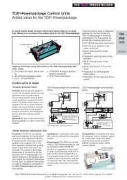
TOX®-Pneumohydraulic Unit Type KT
TOX®-Pneumohydraulic Unit Type KT
TOX®-Pneumohydraulic Unit Type KT
Create successful ePaper yourself
Turn your PDF publications into a flip-book with our unique Google optimized e-Paper software.
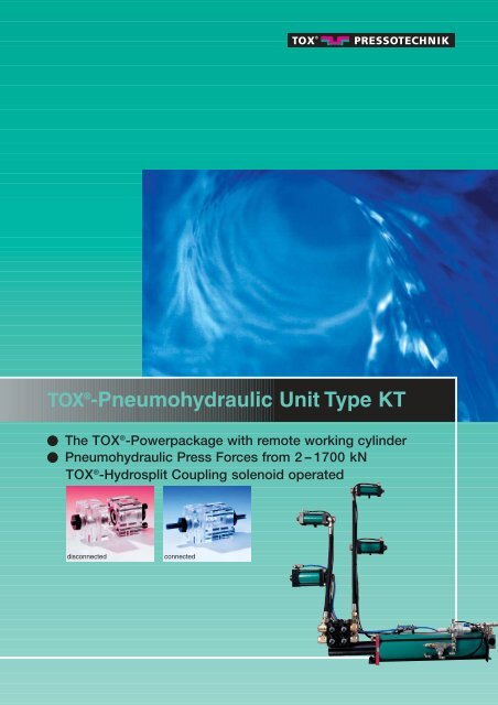
TOX ® -<strong>Pneumohydraulic</strong> <strong>Unit</strong> <strong>Type</strong> <strong>KT</strong><br />
The TOX ® -Powerpackage with remote working cylinder<br />
<strong>Pneumohydraulic</strong> Press Forces from 2 – 1700 kN<br />
TOX ® -Hydrosplit Coupling solenoid operated<br />
disconnected connected
2<br />
<strong>Type</strong> x = L or O<br />
TOX ® -Hydraulic Cylinder HZL and HZO max. 250 bar oil pressure<br />
All new hydraulic cylinders are supplied<br />
in the suitable execution. For the choice<br />
of the cylinder the type of medium<br />
for the return stroke decides whether<br />
the type HZL with air driven return stroke<br />
or the oil driven type HZO is more<br />
suitable. The hydraulic cylinder HZL<br />
<strong>Type</strong> HZ 29/48/74 <strong>Type</strong> HZ 02/05/07/11/19<br />
Version<br />
Stroke<br />
U<br />
1 High pressure connection<br />
2 Bleed screw<br />
3 Special guiding system<br />
4 Return stroke (observe max.<br />
allowed return force “FRHmax”<br />
for oil/oil operation)<br />
5 Absolute air/oil separation (HZL)<br />
6 Tie rod<br />
Order no.<br />
Max. press force<br />
at 250 bar oil pressure<br />
Fast approach force<br />
at 6 bar<br />
Retractive force<br />
at 6 bar<br />
Retractive force (FRHmax)<br />
max with oil/oil operation<br />
W<br />
F<br />
H<br />
L<br />
V<br />
V F1 F2 per 100 mm<br />
mm kN daN daN kN cm 3<br />
hose length<br />
HZx 2.101. 50 23 17 10 9 0,9 0,9 0,2<br />
HZx 2.101.100 23 17 10 9 0,9 1,7 0,2<br />
HZx 2.101.150 23 17 10 9 0,9 2,4 0,2<br />
HZx 2.101.200 23 17 10 9 0,9 3,2 0,2<br />
HZx 5.101. 50 48 40 25 20 2,0 2,2 0,5<br />
HZx 5.101.100 48 40 25 20 2,0 4,3 0,5<br />
HZx 5.101.150 48 40 25 20 2,0 6,5 0,5<br />
HZx 5.101.200 48 40 25 20 2,0 8,6 0,5<br />
HZx 7.101. 50 76 70 35 25 3,1 3,4 0,6<br />
HZx 7.101.100 76 70 35 25 3,1 6,9 0,6<br />
HZx 7.101.150 76 70 35 25 3,1 10,3 0,6<br />
HZx 7.101.200 76 70 35 25 3,1 13,7 0,6<br />
HZx 11.101. 50 108 115 70 25 4,4 4,9 0,6<br />
HZx 11.101.100 108 115 70 25 4,4 9,7 0,6<br />
HZx 11.101.150 108 115 70 25 4,4 14,6 0,6<br />
HZx 11.101.200 108 115 70 25 4,4 19,4 0,6<br />
HZx 19.101. 50 192 210 125 40 7,9 8,6 0,7<br />
HZx 19.101.100 192 210 125 40 7,9 17,3 0,7<br />
HZx 19.101.150 192 210 125 40 7,9 25,9 0,7<br />
HZx 19.101.200 192 210 125 40 7,9 34,5 0,7<br />
HZx 29.101. 50 300 355 235 110 12,3 13,5 0,7<br />
HZx 29.101.100 300 355 235 110 12,3 27,0 0,7<br />
HZx 29.101.150 300 355 235 110 12,3 40,6 0,7<br />
HZx 29.101.200 300 355 235 110 12,3 54,1 0,7<br />
HZx 48.101. 50 492 630 390 245 20,1 22 0,7<br />
HZx 48.101.100 492 630 390 245 20,1 44 0,7<br />
HZx 48.101.150 492 630 390 245 20,1 66 0,7<br />
HZx 48.101.200 492 630 390 245 20,1 88 0,7<br />
HZx 74.101. 50 770 1050 655 245 31,4 35 0,7<br />
HZx 74.101.100 770 1050 655 245 31,4 70 0,7<br />
HZx 74.101.150 770 1050 655 245 31,4 105 0,7<br />
HZx 74.101.200 770 1050 655 245 31,4 140 0,7<br />
M K<br />
B A<br />
G R Connection E<br />
X<br />
C<br />
1<br />
2<br />
3<br />
Example HZL<br />
Adaptor with internal thread to fit the piston rod end<br />
ØA<br />
L<br />
V<br />
W<br />
M<br />
www.tox-en.com<br />
B<br />
L1<br />
SW<br />
15.201010.en<br />
features absolute air/oil separation and<br />
allows the return stroke with air pressure<br />
(min. 3 bar). Only the HZO features<br />
special seals for oil/oil operation and<br />
can be used with hydraulic units with<br />
max. 250 bar oil pressure for the<br />
return stroke. Please observe the<br />
3<br />
4<br />
required volume displacement per 1 mm total<br />
stroke always take total stroke of cylinder<br />
2<br />
5<br />
Calculation for system selection<br />
max. oil pressure<br />
bar<br />
250 max. press<br />
force kN<br />
for application (kN)<br />
Calculation of the volumetric displacement power stroke<br />
required volume<br />
displacement per V 2,0 x required power 12 + factor 1 de-<br />
stroke for applipending on F1<br />
1 mm power stroke<br />
cation (mm)<br />
total stroke<br />
1<br />
6<br />
N<br />
D<br />
N<br />
Typ <strong>Type</strong> HZ HZ 48 48 <strong>Type</strong> Typ HZ HZ 74 74<br />
A<br />
D<br />
C C<br />
HZ with total stroke adjustment version<br />
151 and ISO execution on request<br />
: 48 x required press force 40 = required oil pressure 208<br />
Calculation of volumetric displacement fast approach stroke<br />
V<br />
max. allowable retract forces as<br />
shown on the table below, dependent<br />
on type. Up to 6 hydraulic cylinders<br />
HZ can be normally connected to one<br />
air-to-oil intensifier ES (more are possible<br />
on request).<br />
<strong>Type</strong> HZ 02/05/07/11/19/29<br />
2,0<br />
4,3 +<br />
total stroke of<br />
cylinder in mm<br />
A B C D E F f7 G H K L M N W V g6 R U X<br />
Dimensions in mm<br />
See data sheet 10.00 TOX ® 55 160 6xM6x12 42 G1/8 32 9,5 16 27 M12x1,5 12 14 4 10 10 - G1/4<br />
55 210 6xM6x12 42 G1/8 32 9,5 16 27 M12x1,5 12 14 4 10 10 - G1/4<br />
55 260 6xM6x12 42 G1/8 32 9,5 16 27 M12x1,5 12 14 4 10 10 - G1/4<br />
55 310 6xM6x12 42 G1/8 32 9,5 16 27 M12x1,5 12 14 4 10 10 - G1/4<br />
65 190 6xM8x12 54 G3/8 40 10 25 25 M16x1,5 15 19 4 14 14 - G1/2<br />
65 240 6xM8x12 54 G3/8 40 10 25 25 M16x1,5 15 19 4 14 14 - G1/2<br />
65 290 6xM8x12 54 G3/8 40 10 25 25 M16x1,5 15 19 4 14 14 - G1/2<br />
65 340 6xM8x12 54 G3/8 40 10 25 25 M16x1,5 15 19 4 14 14 - G1/2<br />
80 210 6xM8x16 65 G3/8 52 10 35 25 M24x1,5 19 30 6 22 18 - G3/4<br />
80 260 6xM8x16 65 G3/8 52 10 35 25 M24x1,5 19 30 6 22 18 - G3/4<br />
80 310 6xM8x16 65 G3/8 52 10 35 25 M24x1,5 19 30 6 22 18 - G3/4<br />
80 360 6xM8x16 65 G3/8 52 10 35 25 M24x1,5 19 30 6 22 18 - G3/4<br />
90 210 6xM10x16 68 G3/8 52 10 35 25 M24x1,5 19 30 6 22 18 - G3/4<br />
90 260 6xM10x16 68 G3/8 52 10 35 25 M24x1,5 19 30 6 22 18 - G3/4<br />
90 310 6xM10x16 68 G3/8 52 10 35 25 M24x1,5 19 30 6 22 18 - G3/4<br />
90 360 6xM10x16 68 G3/8 52 10 35 25 M24x1,5 19 30 6 22 18 - G3/4<br />
125 235 6xM16x25 100 G1/2 75 10 50 28 M30x2 25 41 7 26 24 - G1<br />
125 285 6xM16x25 100 G1/2 75 10 50 28 M30x2 25 41 7 26 24 - G1<br />
125 335 6xM16x25 100 G1/2 75 10 50 28 M30x2 25 41 7 26 24 - G1<br />
125 385 6xM16x25 100 G1/2 75 10 50 28 M30x2 25 41 7 26 24 - G1<br />
160 298 6xM20x30 115 G3/4 80 15 55 47 M39x2 35 50 - - 27 22 G1<br />
160 348 6xM20x30 115 G3/4 80 15 55 47 M39x2 35 50 - - 27 22 G1<br />
160 398 6xM20x30 115 G3/4 80 15 55 47 M39x2 35 50 - - 27 22 G1<br />
160 448 6xM20x30 115 G3/4 80 15 55 47 M39x2 35 50 - - 27 22 G1<br />
200 300 8xM20x30 150 G3/4 125 25 80 60 M64x2 60 70 - - 27 30 G1<br />
200 350 8xM20x30 150 G3/4 125 25 80 60 M64x2 60 70 - - 27 30 G1<br />
200 400 8xM20x30 150 G3/4 125 25 80 60 M64x2 60 70 - - 27 30 G1<br />
200 450 8xM20x30 150 G3/4 125 25 80 60 M64x2 60 70 - - 27 30 G1<br />
275 366 10xM24x40 200 G3/4 150 25 100 65 M64x2 60 85 - - 38 30 G1<br />
275 416 10xM24x40 200 G3/4 150 25 100 65 M64x2 60 85 - - 38 30 G1<br />
275 466 10xM24x40 200 G3/4 150 25 100 65 M64x2 60 85 - - 38 30 G1<br />
275 516 10xM24x40 200 G3/4 150 25 100 65 M64x2 60 85 - - 38 30 G1<br />
-Powerpackage for mounting specifications, pressure tolerances ± 5 %<br />
x<br />
N<br />
for application (bar)<br />
factor 2 per<br />
100 mm<br />
hose length<br />
F2<br />
A<br />
D<br />
(0,5x10)<br />
<strong>Type</strong> Fits to ØA B L1 L M W Vg6 SW<br />
HZZ 012.016.020.000 HZx2 22 20 M12x1,5 M16x1,5 15 4 14 19<br />
HZZ 016.022.020.000 HZx5 30 20 M16x1,5 M22x2 20 7 18 27<br />
HZZ 024.030.030.000 HZx7/HZx11 45 30 M24x1,5 M30x2 25 7 26 41<br />
HZZ 030.039.040.000 HZx19 56 40 M30x2 M39x2 35 - - 50<br />
100<br />
STOP<br />
+ 1,4<br />
(ZHK18)
TOX ® -Intensifier ES with fast approach function<br />
The power intensifier with absolute<br />
air/oil separation and integrated<br />
bypass for reliable operation. Can be<br />
mounted in any orientation.<br />
=<br />
=<br />
1<br />
2<br />
3<br />
4<br />
ØF<br />
ZHK 018 1<br />
X<br />
W<br />
D<br />
2<br />
E<br />
3 4<br />
G<br />
required volumetric<br />
displacement for<br />
power stroke (cm 3 )<br />
9 5 6 7 11<br />
8<br />
required volumetric displacement<br />
for fast<br />
approach stroke (cm 3 )<br />
B V<br />
Includes all valves for automatic changeover<br />
from fast approach to power<br />
stroke, and the air spring regulator.<br />
Uses simple pneumatic controls like<br />
any double acting pneumatic cylinder.<br />
O<br />
10<br />
4<br />
34,7 x Number of<br />
metric displacement<br />
2<br />
= 69,4<br />
cylinders<br />
Required total volu-<br />
power stroke for application<br />
(cm 3 )<br />
Required total volu-<br />
x Number of<br />
metric displacement<br />
200 2<br />
= 400<br />
cylinders<br />
H±0,3<br />
A<br />
Y<br />
Order no. A B C D E F G H O V W X Y Connection<br />
fast approach stroke<br />
for application (cm 3 )<br />
Calculated oilpressure<br />
1<br />
208 : 54 = 3,85<br />
Dimensions in mm *Caution: theoretical pressure and power values shown may differ from values on actual pressure table. ** Pressure tolerance ± 5%<br />
“Your way to find the right <strong>KT</strong> system” = values corresponding to your application<br />
C<br />
12 1 2<br />
High pressure<br />
hose<br />
Back pressure<br />
line for flow<br />
control X<br />
1 High pressure port<br />
2 High pressure measuring<br />
and control connection<br />
3 Oil filling nipple<br />
4 Bleed plate<br />
5 Air connection<br />
fast approach stroke<br />
3 8 4 9 7 6 11<br />
Required air pressure<br />
for application<br />
(bar)<br />
The actual required press force, e. g. 40 kN, leads to the selection of a cylinder with max. 48 kN press force. The calculation<br />
results in 208 bar required oil pressure.<br />
The volume required for your case can be found by multiplying the required power stroke, e.g. 12 mm, times the type<br />
specific volume factor V (e.g. 2). The factor F1 + F2 is added to the previous result (whereby F2 depends on the hose<br />
length, e.g. 1000 mm). Then, add a factor of 1.4 for each ZHK 018 Hydrosplit coupling. Finally, multiply by the number of<br />
cylinders, e.g. 2, resulting in a required oil volume of 69.4 cm3 . This leads to selection of an ES with 85 cm3 .<br />
The stroke required for your application leads you to selection of a cylinder with a total stroke of 100 mm, which multiplied<br />
times the volumetric factor V and the number of cylinders, e.g 2 , results in a total volumetric displacement of 400 cm3 .<br />
Check this value against that of the selected intensifier, e.g. 1300 cm3 , which in this example is enough.<br />
The oil pressure calculated in step 1 , in this case 208 bar, is divided by the oil pressure produced by the intensifier at<br />
1 bar air pressure, e.g. 54 bar. The result is the required air pressure for the application. In order to obtain high stroke<br />
frequencies, the air pressure should always be about 20% higher. Caution: the maximum pressure/press force of the<br />
cylinder must not be exceeded.<br />
When using different cylinders and different hose lengths, the calculation of the volume must be done individually<br />
for each cylinder. Then add the combined results.<br />
Fast approach<br />
Connection<br />
Return stroke<br />
For CAD downloads,<br />
please visit us at<br />
www.tox-en.com<br />
Closed oil system. Hose connection<br />
with TOX ® -Hydrosplit coupling. Color<br />
coded pneumatic plug-in system.<br />
Simply perfect.<br />
Connection<br />
High pressure<br />
5<br />
Volumetric<br />
displacement<br />
for fast<br />
app. stroke<br />
cm 3<br />
“OR” Valve<br />
Flow control X<br />
15.201010.en<br />
Power stroke<br />
sequence valve<br />
6 Air connection return stroke<br />
7 Return stroke air line<br />
8 Oil level indicator<br />
9 Patented anti-overfill device<br />
10 Intensifier piston<br />
11 Air spring valve<br />
12 Hydrosplit coupling<br />
Volumetric<br />
displacement<br />
for<br />
power stroke<br />
cm 3<br />
Oil pressure<br />
at<br />
1 bar air<br />
pressure<br />
bar<br />
www.tox-en.com<br />
Max. Max.<br />
air pres- oil pressuresure<br />
ES 100.100.022.70 110 551 64 9 15 90 22,5 85 265 110 234 max. 100 240 G1/2 G1/2 G3/4 360 22 57* 6 345**<br />
ES 160.100.085.64 170 731 86 9 15 95 22,5 85 330 130 303 max. 100 300 G3/4 G3/4 G3/4 1300 85 54* 6 328**<br />
ES 250.100.216.80 267 886 134,5 9 15 130 22,5 85 427 150 395 max. 100 340 G1 G1 G3/4 4600 216 66* 6 400**<br />
ES 300.100.381.62 324 867 167 14 20 130 92 100 484 150 379 max. 100 400 G1 G1 G3/4 6100 381 52* 6 316**<br />
ES 350.100.500.76 368 1075 189 14 20 145 92 100 528 150 450 max. 100 420 G1 G1 G3/4 10700 500 64* 6 388**<br />
ES 350.100.830.76 368 1457 189 14 20 145 92 100 528 150 709 max. 100 420 G1 G1 G3/4 15000 830 64* 6 388**<br />
ES 100.100.039.39 110 551 64 9 15 90 22,5 85 265 110 234 max. 100 240 G1/2 G1/2 G3/4 350 39 35* 10 355**<br />
ES 160.100.134.41 170 731 86 9 15 90 22,5 85 330 130 303 max. 100 300 G3/4 G3/4 G3/4 1300 134 36* 10 365**<br />
ES 250.100.395.43 267 886 134,5 9 15 130 22,5 85 427 150 395 max. 100 340 G1 G1 G3/4 4600 395 38* 10 385**<br />
ES 300.100.665.36 324 867 167 14 20 130 92 100 484 150 379 max. 100 400 G1 G1 G3/4 6000 665 33* 10 330**<br />
ES 350.100.844.45 368 1075 189 14 20 145 92 100 528 150 450 max. 100 420 G1 G1 G3/4 10600 844 41* 10 410**<br />
bar<br />
bar<br />
3
Order no.<br />
4<br />
type<br />
TOX ® -Working Cylinder AT max. 400 bar oil pressure<br />
The pneumo-hydraulic cylinder with<br />
double-bearing working piston.<br />
Fast approach and return stroke by<br />
stroke<br />
Max. press force<br />
at 400 bar oil pressure<br />
Return stroke<br />
Fast approach force ***<br />
at 6 bar<br />
Retractive force<br />
at 6 bar<br />
Connection E Fast approach stroke<br />
V F1 F2 per<br />
100 mm<br />
mm kN daN daN cm 3 hose length<br />
AT 1. 50. 13 69 72 0,31 0,6 0,4<br />
AT 1. 100. 13 69 72 0,31 1,0 0,4<br />
AT 1. 200. 13 69 72 0,31 1,8 0,4<br />
AT 1. 250. 13 69 72 0,31 2,3 0,4<br />
AT 2. 50. 21 140 150 0,49 0,8 0,7<br />
AT 2. 100. 21 140 150 0,49 1,4 0,7<br />
AT 2. 200. 21 140 150 0,49 2,6 0,7<br />
AT 2. 300. 21 140 150 0,49 3,9 0,7<br />
AT 4. 50. 42 180 195 1,02 2,3 0,7<br />
AT 4. 100. 42 180 195 1,02 3,1 0,7<br />
AT 4. 200. 42 180 195 1,02 5,6 0,7<br />
AT 4. 300. 42 180 195 1,02 8,1 0,7<br />
AT 4. 400. 42 180 195 1,02 10,6 0,7<br />
AT 8. 50. 81 320 330 1,96 4,1 0,9<br />
AT 8. 100. 81 320 330 1,96 6,5 0,9<br />
AT 8. 200. 81 320 330 1,96 11,2 0,9<br />
AT 8. 300. 81 320 330 1,96 15,9 0,9<br />
AT 8. 400. 81 320 330 1,96 20,6 0,9<br />
AT 15. 50. 158 450 550 3,85 8,4 1,1<br />
AT 15. 100. 158 450 550 3,85 12,9 1,1<br />
AT 15. 200. 158 450 550 3,85 22,0 1,1<br />
AT 15. 300. 158 450 550 3,85 31,0 1,1<br />
AT 15. 400. 158 450 550 3,85 40,0 1,1<br />
AT 30. 50. 320 660 930 7,85 17,4 1,1<br />
AT 30. 100. 320 660 930 7,85 26,5 1,1<br />
AT 30. 200. 320 660 930 7,85 44,7 1,1<br />
AT 30. 300. 320 660 930 7,85 62,8 1,1<br />
AT 30. 400. 320 660 930 7,85 81,0 1,1<br />
AT 50. 50. 498 720 1200 12,27 18,2 1,1<br />
AT 50. 100. 498 720 1200 12,27 34,8 1,1<br />
AT 50. 200. 498 720 1200 12,27 62,7 1,1<br />
AT 50. 300. 498 720 1200 12,27 90,5 1,1<br />
AT 100. 100. 1030 1260 2200 25,45 71,5 3,1<br />
AT 100. 200. 1030 1260 2200 25,45 128,7 3,1<br />
AT 100. 300. 1030 1260 2200 25,45 185,9 3,1<br />
AT 170. 200. 1670 1570 2530 41,55 178,8 3,1<br />
1<br />
2<br />
3<br />
applying pressure to the working<br />
part. This results in high fast<br />
approach and return stroke forces.<br />
Calculation for system selection<br />
max. oil pressure<br />
bar<br />
400 max. press<br />
force kN<br />
application (kN)<br />
Calculation of the volumetric displacement power stroke<br />
Required volumetric<br />
displacement per 1<br />
1,96 x required power<br />
V<br />
stroke for the<br />
12 + factor 1 depending<br />
on F1<br />
mm power stroke<br />
application (mm) total stroke<br />
Required volumetric displacement per 1 mm<br />
total stroke, always take total stroke of cylinder<br />
: 81 x required press force for 50 = required oil pressure 246 STOP<br />
Calculation of volumetric displacement fast approach stroke<br />
AT 01-30 AT 50<br />
AT 100 AT 170/200<br />
V<br />
1,96<br />
Absolute separation of air and oil. Up<br />
to 6 working units AT can be connected<br />
to an air-to-oil intensifier ES.<br />
AT with total stroke adjustment<br />
Version 51 on request<br />
x<br />
6,5 +<br />
factor 2 per<br />
100 mm<br />
hose length<br />
total stroke of<br />
cylinder mm<br />
1 Control throttle for<br />
start of power stroke<br />
2 Oil high pressure<br />
measuring connection<br />
3 Power stroke air<br />
connection to ES<br />
4 High pressure port<br />
from ES<br />
5 Bleed screw<br />
6 Special seals<br />
7 Absolute air/oil<br />
separation<br />
8 Double supported<br />
working piston<br />
9 Tie rod<br />
for application (bar)<br />
F2<br />
(0,9x10) + 1,5 (ZHK18)<br />
A B C D E Ff7 G H K L M N R S U X Vg6 W<br />
50 229 6xM6x11 40 G1/8 30 10 16 24 M12x1,5 12 14 11,5 106,5 6 G1/2 - -<br />
50 329 6xM6x11 40 G1/8 30 10 16 24 M12x1,5 12 14 11,5 156,5 6 G1/2 - -<br />
50 529 6xM6x11 40 G1/8 30 10 16 24 M12x1,5 12 14 11,5 256,5 6 G1/2 - -<br />
50 629 6xM6x11 40 G1/8 30 10 16 24 M12x1,5 12 14 11,5 306,5 6 G1/2 - -<br />
70 242 6xM8x12 54 G1/4 40 10 20 26 M16x1,5 15 17 13 116 8 G1/2 - -<br />
70 342 6xM8x12 54 G1/4 40 10 20 26 M16x1,5 15 17 13 166 8 G1/2 - -<br />
70 542 6xM8x12 54 G1/4 40 10 20 26 M16x1,5 15 17 13 266 8 G1/2 - -<br />
70 742 6xM8x12 54 G1/4 40 10 20 26 M16x1,5 15 17 13 366 8 G1/2 - -<br />
85 258 6xM8x15 64 G3/8 50 10 30 28,5 M22x2 20 24 14 125 10 G1/2 18 7<br />
85 355 6xM8x15 64 G3/8 50 10 30 28,5 M22x2 20 24 14 175 10 G1/2 18 7<br />
85 555 6xM8x15 64 G3/8 50 10 30 28,5 M22x2 20 24 14 275 10 G1/2 18 7<br />
85 755 6xM8x15 64 G3/8 50 10 30 28,5 M22x2 20 24 14 375 10 G1/2 18 7<br />
85 955 6xM8x15 64 G3/8 50 10 30 28,5 M22x2 20 24 14 475 10 G1/2 18 7<br />
110 288 6xM10x16 88 G1/2 70 10 45 35 M30x2 25 36 17 133 12 G3/4 26 7<br />
110 371 6xM10x16 88 G1/2 70 10 45 35 M30x2 25 36 17 183 12 G3/4 26 7<br />
110 571 6xM10x16 88 G1/2 70 10 45 35 M30x2 25 36 17 283 12 G3/4 26 7<br />
110 771 6xM10x16 88 G1/2 70 10 45 35 M30x2 25 36 17 383 12 G3/4 26 7<br />
110 971 6xM10x16 88 G1/2 70 10 45 35 M30x2 25 36 17 483 12 G3/4 26 7<br />
135 293 6xM16x25 100 G1/2 75 15 50 36 M30x2 25 41 17,5 134,5 16 G1 26 7<br />
135 381 6xM16x25 100 G1/2 75 15 50 36 M30x2 25 41 17,5 185 16 G1 26 7<br />
135 581 6xM16x25 100 G1/2 75 15 50 36 M30x2 25 41 17,5 285 16 G1 26 7<br />
135 781 6xM16x25 100 G1/2 75 15 50 36 M30x2 25 41 17,5 385 16 G1 26 7<br />
135 981 6xM16x25 100 G1/2 75 15 50 36 M30x2 25 41 17,5 485 16 G1 26 7<br />
170 362 6xM20x30 132 G3/4 100 18 56 47 M39x2 35 50 20 186 22 G1 - -<br />
170 425 6xM20x30 132 G3/4 100 18 56 47 M39x2 35 50 20 236 22 G1 - -<br />
170 625 6xM20x30 132 G3/4 100 18 56 47 M39x2 35 50 20 336 22 G1 - -<br />
170 825 6xM20x30 132 G3/4 100 18 56 47 M39x2 35 50 20 436 22 G1 - -<br />
170 1025 6xM20x30 132 G3/4 100 18 56 47 M39x2 35 50 20 536 22 G1 - -<br />
200 390 8xM20x30 150 G3/4 115 25 63 52 M42x2 40 55 23 193 30 G1 - -<br />
200 440 8xM20x30 150 G3/4 115 25 63 52 M42x2 40 55 23 243 30 G1 - -<br />
200 640 8xM20x30 150 G3/4 115 25 63 52 M42x2 40 55 23 343 30 G1 - -<br />
200 840 8xM20x30 150 G3/4 115 25 63 52 M42x2 40 55 23 443 30 G1 - -<br />
310 534 12xM24x40 200 G1 150 25 100 60 M64x2 60 85 35 253 30 SAE - -<br />
310 734 12xM24x40 200 G1 150 25 100 60 M64x2 60 85 35 353 30 flange - -<br />
310 934 12xM24x40 200 G1 150 25 100 60 M64x2 60 85 35 453 30 2” - -<br />
420 844 18xM30x55 320 G1” 240 35 150 70 M80x2 80 4xØ16 99 353 30 SAE 2” - -<br />
AT 200 on request ***Approach stroke assist available on request Dimensions in mm See data sheet 10.00 TOX ® -Powerpackage for mounting specifications, pressure tolerances ± 5 %<br />
www.tox-en.com<br />
15.201010.en<br />
100<br />
11(ZHK42)
TOX ® -Intensifier ES with fast approach function<br />
The power intensifier with absolute<br />
air/oil separation and integrated<br />
bypass for reliable operation. Can be<br />
mounted in any orientation.<br />
=<br />
=<br />
1<br />
2<br />
3<br />
4<br />
ØF<br />
ZHK 018 1<br />
X<br />
ES 100.100 ... - ES 350.100 ... (not for AT100 and AT170)<br />
W<br />
8<br />
D<br />
2<br />
E<br />
3 4<br />
G<br />
required volumetric<br />
displacement for<br />
power stroke (cm 3 )<br />
9 5 6 7 11<br />
required volumetric<br />
displacement for fast<br />
approach stroke (cm 3 )<br />
10<br />
B V<br />
ES 300.12 ... - ES 350.12 ... (for AT100 and AT170)<br />
ZHK 042 1 2 3 4 9 5 6 7<br />
ØF<br />
D<br />
E G<br />
X W<br />
B<br />
Includes all valves for automatic changeover<br />
from fast approach to power<br />
stroke, and the air spring regulator.<br />
Uses simple pneumatic controls like<br />
any double acting pneumatic cylinder.<br />
V<br />
O<br />
O<br />
C<br />
C<br />
4<br />
40,52 x Number of<br />
metric displacement<br />
2<br />
= 81,04<br />
cylinders<br />
Required total volu-<br />
power stroke for application<br />
(cm 3 )<br />
Required total volu-<br />
x Number of<br />
metric displacement<br />
196 2<br />
= 392<br />
cylinders<br />
H±0,3<br />
A<br />
Y<br />
H±0,3<br />
A<br />
Y<br />
Order no. A B C D E F G H O V W X Y Connection<br />
fast approach stroke<br />
for application (cm 3 )<br />
Fast<br />
approach<br />
Connection<br />
Return stroke<br />
Closed oil system. Hose connection<br />
with TOX ® -Hydrosplit coupling. Color<br />
coded pneumatic plug-in system.<br />
Simply perfect.<br />
12 1 2<br />
High<br />
pressure hose<br />
Back pressure<br />
line for flow<br />
control X<br />
1 High pressure port<br />
2 High pressure<br />
measuring and<br />
control connection<br />
3 Oil filling nipple<br />
4 Bleed plate<br />
5 Air connection<br />
fast approach stroke<br />
Calculated oil<br />
pressure 1<br />
3 8 4 9 7 6 11<br />
6 Air connection return stroke<br />
7 Return stroke air line<br />
8 Oil level indicator<br />
9 Patented anti-overfill device<br />
10 Intensifier piston<br />
11 Air spring valve<br />
12 Hydrosplit coupling<br />
246 : 54 = 4,55<br />
Required air pressure<br />
for application<br />
(bar)<br />
Dimensions in mm *Caution: theoretical pressure and power values shown may differ from values on actual pressure table. ** Pressure tolerance ± 5%<br />
The actual required press force, e. g. 50 kN, leads to the selection of a cylinder with max. 81 kN press force. The calculation results in<br />
246 bar required oil pressure.<br />
The volume required for your case can be found by multiplying the required power stroke, e.g. 12 mm, times the type specific volume<br />
factor V (e.g. 1.96). The factor F1 + F2 is added to the previous result (whereby F2 depends on the hose length, e.g. 1000 mm). Then,<br />
add a factor of 1.5 for each ZHK 018 Hydrosplit coupling. Finally, multiply by the number of cylinders, e.g. 2 , resulting in a required oil<br />
volume of 81.04 cm3 . This leads to selection of an ES with 85 cm3 .<br />
The stroke required for your application leads you to selection of a cylinder with a total stroke of 100 mm, which multiplied times the<br />
volumetric factor V and the number of cylinders, e.g. 2, results in a total volumetric displacement of 392 cm3 . Check this value against<br />
that of the selected intensifier, e.g. 1300 cm3 “Your way to find the right <strong>KT</strong> system” = values corresponding to your application<br />
, which in this example is enough.<br />
The oil pressure calculated in step 1 , in this case 246 bar, is divided by the oil pressure produced by the intensifier at 1 bar air pressure,<br />
e.g. 54 bar. The result is the required air pressure for the application. In order to obtain high stroke frequencies, the air pressure should<br />
always be about 20% higher. Caution: the maximum pressure/press force of the cylinder must not be exceeded.<br />
When using different cylinders and different hose lengths, the calculation of the volume must be done individually for each<br />
cylinder. Then add the combined results.<br />
15.201010.en www.tox-en.com 5<br />
Connection<br />
High<br />
pressure<br />
5<br />
Volumetric<br />
displacement<br />
for<br />
fast app.<br />
stroke cm 3<br />
“OR” Valve<br />
Flow control X<br />
Power stroke<br />
sequence valve<br />
Volumetric<br />
displacement<br />
for<br />
power stroke<br />
cm3 Oil pressure<br />
at<br />
1 bar air<br />
pressure<br />
bar<br />
ES 100.100.022.70 110 551 64 9 15 90 22,5 85 265 110 234 max. 100 240 G1/2 G1/2 G3/4 360 22 57* 6 345**<br />
ES 160.100.085.64 170 731 86 9 15 95 22,5 85 330 130 303 max. 100 300 G3/4 G3/4 G3/4 1300 85 54* 6 328**<br />
ES 250.100.216.80 267 886 134,5 9 15 130 22,5 85 427 150 395 max. 100 340 G1 G1 G3/4 4600 216 66* 6 400**<br />
ES 300.100.381.62 324 867 167 14 20 130 92 100 484 150 379 max. 100 400 G1 G1 G3/4 6100 381 52* 6 316**<br />
ES 350.100.500.76 368 1075 189 14 20 145 92 100 528 150 450 max. 100 420 G1 G1 G3/4 10700 500 64* 6 388**<br />
ES 350.100.830.76 368 1457 189 14 20 145 92 100 528 150 709 max. 100 420 G1 G1 G3/4 15000 830 64* 6 388**<br />
ES 100.100.039.39 110 551 64 9 15 90 22,5 85 265 110 234 max. 100 240 G1/2 G1/2 G3/4 350 39 35* 10 355**<br />
ES 160.100.134.41 170 731 86 9 15 90 22,5 85 330 130 303 max. 100 300 G3/4 G3/4 G3/4 1300 134 36* 10 365**<br />
ES 250.100.395.43 267 886 134,5 9 15 130 22,5 85 427 150 395 max. 100 340 G1 G1 G3/4 4600 395 38* 10 385**<br />
ES 300.100.665.36 324 867 167 14 20 130 92 100 484 150 379 max. 100 400 G1 G1 G3/4 6000 665 33* 10 330**<br />
ES 350.100.844.45 368 1075 189 14 20 145 92 100 528 150 450 max. 100 420 G1 G1 G3/4 10600 844 41* 10 410**<br />
ES 350. 12.381.62 324 867 167 14 20 130 92 100 484 150 379 max. 205 400 G1 G1 SAE2” 6100 381 52* 6 316**<br />
ES 350. 12.500.76 368 1075 189 14 20 145 92 100 528 150 450 max. 205 420 G1 G1 SAE2” 10700 50 64* 6 388**<br />
ES 350. 12.830.76 368 1457 189 14 20 145 92 100 528 150 709 max. 205 420 G1 G1 SAE2” 15000 830 64* 6 388**<br />
ES 350. 12.844.45 368 1075 189 14 20 145 92 100 528 150 450 max. 205 420 G1 G1 SAE2” 10600 844 41* 10 410**<br />
Max.<br />
air<br />
pressure<br />
bar<br />
Max.<br />
oil pressure<br />
bar
6<br />
Hydraulic hoses<br />
The connection between the drive cylinders and the<br />
pneumo-hydraulic intensifier<br />
Variant no. Cylinder HZ/AT side Intensifier ES side Connection<br />
ZS 01 2 x straight connection<br />
A<br />
ZS 02 1 x 90° elbow on ES<br />
1 x straight connection<br />
on HZ/AT<br />
Hose length<br />
B<br />
ZS 03 1 x straight connection on ES<br />
1 x 90° elbow on HZ/AT<br />
Ordering example for hoses:<br />
ZS 01 - 1000<br />
hose length<br />
variant no.<br />
Hydraulic<br />
cylinder<br />
HZ/AT<br />
H<br />
R min<br />
www.tox-en.com<br />
H<br />
<strong>TOX®</strong> -Hydrosplit-<br />
Coupling<br />
Intensifier ES<br />
Example for the right and wrong installation of hoses<br />
wrong<br />
right<br />
wrong<br />
right<br />
C<br />
Allocation of the hydraulic hoses to the drive cylinders<br />
Drive Standard Hose dimensions [mm]<br />
hose lengths [mm] A B C Hmin Rmin<br />
AT1 500/1000/2000/3000 88 75 84 220 150<br />
AT2/AT4 500/1000/2000/3000 94 85 92 275 200<br />
AT8 500/1000/2000/3000 101 90 74 320 240<br />
AT15/AT30/AT50 500/1000/2000/3000 118 125 137 375 280<br />
AT100 1000/2000/3000 200 200 176 1120 920<br />
AT170 1000/2000/3000 200 200 176 1120 920<br />
HZ2 500/1000/2000/3000 88 75 84 220 150<br />
HZ5 500/1000/2000/3000 94 85 92 275 200<br />
HZ7/HZ11 500/1000/2000/3000 101 90 74 320 240<br />
HZ19/HZ29/HZ48/HZ74 500/1000/2000/3000 118 125 137 375 280<br />
Other connection variants on request Rmin: smallest allowable bending radius<br />
wrong<br />
right<br />
wrong<br />
Mounting variants for TOX ® -Hydrosplit coupling with 1 – 6 hoses.<br />
Swivel fitting allows each hose to be independently oriented.<br />
Standard mounting sequence of the<br />
®<br />
TOX -Hydrosplit Coupling ZHK18<br />
6<br />
4<br />
2<br />
5<br />
3<br />
1<br />
15.201010.en<br />
HZ<br />
AT<br />
HZ<br />
AT<br />
Hydrosplit<br />
coupling<br />
ES<br />
Hydrosplit<br />
coupling<br />
ES<br />
HZ<br />
AT<br />
right<br />
HZ<br />
AT<br />
Mounting style 1 Mounting style 2 Mounting style 3 Mounting style 4<br />
wrong<br />
right<br />
Hydrosplit<br />
coupling<br />
ES<br />
wrong<br />
Hose must be installed so that it can be bled properly!<br />
right<br />
Hydrosplit<br />
coupling<br />
ES<br />
HZ<br />
AT
TOX ® -Hydrosplit Coupling type ZHK<br />
Optimised for flow rate and volume for up to 6 cylinders<br />
In order to ship the components filled with oil and to facilitate installation, we have developed the TOX ® -Hydrosplit<br />
coupling. This coupling allows for connection of the components without any introduction of air to the system and without<br />
any leakage.<br />
TOX ® -Hydrosplit coupling, manually switchable, type ZHK 018.000<br />
Connection hose side + Connection intensifier side Connection hose side + Connection intensifier side<br />
hose<br />
disconnected connected<br />
oil<br />
intensifier<br />
7<br />
3<br />
5<br />
tighten 4 screws,<br />
open 2 slides,<br />
unit ready!<br />
TOX ® -Hydrosplit coupling with solenoid operated valve, type ZHK 018.001<br />
70<br />
24,6 54,4<br />
128<br />
disconnected<br />
Item 1 Item 2<br />
Item 1 Item 2<br />
Can be used with drives up to HZ 74/AT 50.<br />
For bigger cylinders request for ZHK 042.<br />
Order data:<br />
1. Order No. type of the working<br />
section AT or hydraulic cylinder HZ<br />
(HZL for air/oil or HZO for oil/oil).<br />
2. Intensifier ES order no. type<br />
3. Hydraulic hose ZS<br />
variant no., hose length<br />
4. <strong>Type</strong> Hydrosplit coupling<br />
5. Mounting style of the Hydrosplit<br />
coupling<br />
318<br />
70<br />
128<br />
85,9<br />
64<br />
connected<br />
Example:<br />
1. HZL 5.101.100 quantity: 2<br />
(Air/oil operation)<br />
2. ES 160.100.085.64 quantity: 1<br />
3. ZS 01.1000 quantity: 2<br />
4. ZHK 18.000<br />
5. Mounting style 1<br />
1<br />
4<br />
6<br />
2<br />
1 Coupling half – hose side<br />
2 Coupling half – intensifier side<br />
3 Threaded bushing – do not open<br />
4 Bleed screw<br />
5 Coupling assembly screws<br />
6 Coupling mounting screws to intensifier<br />
7 Valve stem to open or close valve<br />
Features:<br />
- Valve is operated with a pneumatic<br />
cylinder. No pressure drop.<br />
- Cylinders can be activated<br />
independently. Return stroke<br />
position can be controlled.<br />
- One valve size can be used on all<br />
cylinders.<br />
- Improved cycle time.<br />
- position feedback prepared<br />
Technical data:<br />
Operating voltage: 24 V/DC<br />
Power consumption: 4.4 W<br />
Includes solenoid DIN 43650 (ISO<br />
4400) design A, with LED<br />
You will receive:<br />
2 x HZL incl. hose and Hydrosplit<br />
coupling part 1.<br />
+ 1 x ES incl. Hydrosplit coupling,<br />
manual, with 2x part 2.<br />
Completely filled with oil and delivered<br />
in detached condition. Ready<br />
for connection including colourcoded<br />
pneumatic plug-in-system.<br />
Operating instruction<br />
15.201010.en<br />
7<br />
www.tox-en.com<br />
7
TOX ® -Pneumo-hydraulic unit type <strong>KT</strong> – the system<br />
Long power strokes, drive of several cylinders, color coded<br />
pneumatic plug-in-system. Optimum system separation by<br />
TOX ® -Hydrosplit coupling.<br />
Energy-saving, total pneumatic<br />
operation, integrated oil system,<br />
absolute air/oil separation, simple<br />
construction. Driven as any normal<br />
double-acting pneumatic cylinder.<br />
Reduced noise level.<br />
The total stroke is divided into<br />
three sections:<br />
- air-operated fast approach<br />
- pneumatic-hydraulic power<br />
stroke<br />
- air-operated return stroke<br />
or<br />
- pneumatic-hydraulic power<br />
stroke only<br />
- air-operated return stroke<br />
Drive variant HZ + ES<br />
2 4<br />
Not included<br />
Hydraulic cylinder HZ<br />
Drive variant AT + ES<br />
2<br />
4<br />
Not included<br />
4<br />
2<br />
X<br />
Working<br />
cylinder AT<br />
X<br />
2<br />
4<br />
The changeover from fast approach<br />
to power stroke is fitted to the<br />
system as a standard feature and<br />
works automatically according to the<br />
dynamic pressure principle. The<br />
speed of the changeover from fast<br />
approach to power stroke can be<br />
regulated via throttle "X".<br />
Connection:<br />
The intensifier ES is connected via a<br />
hydraulic hose and TOX ® hydraulic<br />
coupling with working cylinder AT, or<br />
the TOX ® -Hydraulic cylinder HZ.<br />
The unit is driven by a 4/2 or 5/2way<br />
valve.<br />
Pneumatic<br />
manifold<br />
ZVL<br />
4.2<br />
Throttle “X” Intensifier ES<br />
Throttle “X”<br />
2<br />
4<br />
Pneumatic<br />
manifold<br />
ZVL<br />
4.2<br />
Pressure regulation valve<br />
Pneumatic spring<br />
0,8 bar, firmly set<br />
8<br />
8<br />
Y<br />
Y<br />
X<br />
A<br />
X<br />
A<br />
Intensifier ES<br />
2<br />
14<br />
3 1<br />
Pressure regulation valve<br />
Pneumatic spring<br />
0,8 bar, firmly set<br />
Items supplied:<br />
TOX ® -Intensifier ES with TOX ® working<br />
cylinder AT or TOX ® -Hydraulic<br />
cylinder HZ.<br />
Drive cylinder with hoses and TOX ®<br />
Hydrosplit coupling and intensifier<br />
ES are separately delivered. Simple<br />
assembly by colour-guided pneumatic<br />
plug-in-system of all connection<br />
lines. Completely filled with oil.<br />
Ready for connection.<br />
Drive variant HZx + ES = <strong>KT</strong> ...<br />
Shorter design than working cylinder<br />
AT. Single-bearing working piston.<br />
Low fast approach and retractive<br />
forces.<br />
Fast approach and power strokedrive<br />
by the intensifier ES. Return<br />
stroke obtained by applying compressed<br />
air to the hydraulic cylinder<br />
HZ.<br />
Budget solution!<br />
Absolute air/oil separation for HZL<br />
and special oil/oil seals for HZO.<br />
Drive variant AT + ES = <strong>KT</strong> ...<br />
TOX ® working cylinder AT with<br />
double-bearing working piston. Fast<br />
approach and return stroke obtained<br />
by applying compressed air to the<br />
working cylinder.<br />
Strong fast approach and retractive<br />
forces.<br />
Power stroke obtained via intensifier<br />
ES. Absolute separation of air and<br />
oil.<br />
TOX ® PRESSOTECHNIK Riedstraße 4 D-88250 Weingarten Tel. +49 (0) 751-50 07-0 Fax +49 (0) 7 51-5 23 91<br />
E-Mail: info@tox-de.com www.tox-en.com<br />
6<br />
6<br />
2<br />
14<br />
3 1<br />
For accessories, see<br />
data sheet 10.00<br />
TOX ® -Powerpackage<br />
15.201010.en Subject to technical alternations.


