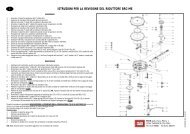
Installer's handbook - 1/3 Types of installation - 2/3 Software guide ...
Installer's handbook - 1/3 Types of installation - 2/3 Software guide ...
Installer's handbook - 1/3 Types of installation - 2/3 Software guide ...

You also want an ePaper? Increase the reach of your titles
YUMPU automatically turns print PDFs into web optimized ePapers that Google loves.
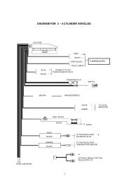
"A"<br />
5A<br />
Fuse<br />
Black<br />
Black<br />
Red<br />
Red<br />
15A<br />
Fuse<br />
"B"<br />
10 Poles<br />
Connector<br />
injectors<br />
connection<br />
1° Petrol<br />
Injector<br />
"F"<br />
Relay<br />
"P2"<br />
+ -<br />
Battery<br />
2° Petrol<br />
Injector<br />
1 2 3 4<br />
LPG<br />
S.V.<br />
"P"<br />
"P1" "P4"<br />
(-) (+)<br />
"P3"<br />
3° Petrol<br />
Injector<br />
Changeover Switch<br />
Connector<br />
"C"<br />
10 Poles<br />
Connector<br />
Auxiliary<br />
connection<br />
4° Petrol<br />
Injector<br />
Petrol<br />
Injectors<br />
Sequence<br />
Gas<br />
Inlet<br />
"G"<br />
"Q"<br />
Gas<br />
temperature<br />
Sensor<br />
Diagnostic<br />
Point<br />
3 2 1<br />
"D"<br />
RAIL<br />
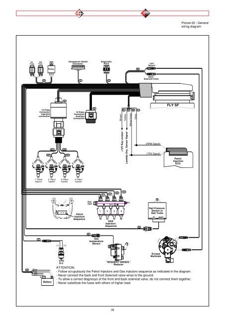
38<br />
Brown<br />
+12V Key contact<br />
"I4"<br />
"I3"<br />
"I2"<br />
"I1"<br />
1 2 3 4<br />
1 2 3 4<br />
GAS<br />
Injectors<br />
Sequence<br />
"O"<br />
Yellow<br />
White/Violet<br />
P1<br />
"SEQUENT GENIUS "<br />
Reducer<br />
"E"<br />
Levl<br />
Sensor<br />
(TPS Signal)<br />
Europa<br />
Multivale<br />
FLY SF<br />
Petrol<br />
Injection<br />
ECU<br />
ATTENTION:<br />
- Follow scrupulously the Petrol Injectors and Gas injectors sequence as indicated in the diagram.<br />
- Never connect the back and front Solenoid valve wires to the ground.<br />
- To allow a correct diagnosys <strong>of</strong> the front and back solenoid valve, do not connect them together.<br />
- Never substitute the fuses with others <strong>of</strong> higher load.<br />
Lambda Oxy. Sensor Signal<br />
"N"<br />
"M"<br />
Grey<br />
"L"<br />
"H"<br />
Back<br />
Solenoid Valve<br />
(RPM Signal)<br />
Rail Pressure<br />
Sensor or<br />
Rail Turbo<br />
P1<br />
MAP<br />
Picture 02 - General<br />
wiring diagram