Componentes de protección TeSys - Ingeniero Borda & Asociados
Componentes de protección TeSys - Ingeniero Borda & Asociados
Componentes de protección TeSys - Ingeniero Borda & Asociados

Create successful ePaper yourself
Turn your PDF publications into a flip-book with our unique Google optimized e-Paper software.
3<br />
Índice 0<br />
3/0<br />
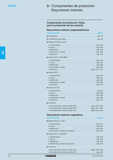
3 - <strong>Componentes</strong> <strong>de</strong> <strong>protección</strong><br />
Disyuntores motores<br />
<strong>Componentes</strong> <strong>de</strong> <strong>protección</strong> <strong>TeSys</strong><br />
para la <strong>protección</strong> <strong>de</strong> los motores<br />
Disyuntores motores magnetotérmicos<br />
Guía <strong>de</strong> elección. . . . . . . . . . . . . . . . . . . . . . . . . . . . . . . . . . . . . . . . . . . . . .pág.3/2<br />
b Presentación. . . . . . . . . . . . . . . . . . . . . . . . . . . . . . . . . . . . . . . . . . . . . . . pág. 3/6<br />
b Características generales. . . . . . . . . . . . . . . . . . . . . . . . . . . . . . . . . . . . . pág. 3/8<br />
b Mo<strong>de</strong>los GV2 ME y GV2 P<br />
v Características . . . . . . . . . . . . . . . . . . . . . . . . . . . . . . . . . . . . . . . . . . pág. 3/10<br />
v Curvas . . . . . . . . . . . . . . . . . . . . . . . . . . . . . . . . . . . . . . . . . . . . . . . . pág. 3/24<br />
v Referencias. . . . . . . . . . . . . . . . . . . . . . . . . . . . . . . . . . . . . . . . . . . . . pág. 3/46<br />
v Dimensiones, montaje . . . . . . . . . . . . . . . . . . . . . . . . . . . . . . . . . . . . pág. 3/66<br />
v Esquemas. . . . . . . . . . . . . . . . . . . . . . . . . . . . . . . . . . . . . . . . . . . . . . pág. 3/72<br />
b Mo<strong>de</strong>lo GV3 P y GV3 ME80<br />
v Características . . . . . . . . . . . . . . . . . . . . . . . . . . . . . . . . . . . . . . . . . . pág. 3/12<br />
v Curvas . . . . . . . . . . . . . . . . . . . . . . . . . . . . . . . . . . . . . . . . . . . . . . . . pág. 3/28<br />
v Referencias. . . . . . . . . . . . . . . . . . . . . . . . . . . . . . . . . . . . . . . . . . . . . pág. 3/48<br />
v Dimensiones, montaje . . . . . . . . . . . . . . . . . . . . . . . . . . . . . . . . . . . . pág. 3/69<br />
v Esquemas. . . . . . . . . . . . . . . . . . . . . . . . . . . . . . . . . . . . . . . . págs. 3/72 y 3/73<br />
b Mo<strong>de</strong>lo GV7 R<br />
v Características . . . . . . . . . . . . . . . . . . . . . . . . . . . . . . . . . . . . . . . . . . pág. 3/13<br />
v Curvas . . . . . . . . . . . . . . . . . . . . . . . . . . . . . . . . . . . . . . . . . . . . . . . . pág. 3/31<br />
v Referencias. . . . . . . . . . . . . . . . . . . . . . . . . . . . . . . . . . . . . . . . . . . . . pág. 3/49<br />
v Dimensiones, montaje . . . . . . . . . . . . . . . . . . . . . . . . . . . . . . . . . . . . pág. 3/69<br />
v Esquemas. . . . . . . . . . . . . . . . . . . . . . . . . . . . . . . . . . . . . . . . . . . . . . pág. 3/73<br />
b Mo<strong>de</strong>lo GV2 RT<br />
v Características . . . . . . . . . . . . . . . . . . . . . . . . . . . . . . . . . . . . . . . . . . . pág. 3/8<br />
v Curvas . . . . . . . . . . . . . . . . . . . . . . . . . . . . . . . . . . . . . . . . . . . . . . . . pág. 3/36<br />
v Referencias. . . . . . . . . . . . . . . . . . . . . . . . . . . . . . . . . . . . . . . . . . . . . pág. 3/50<br />
v Dimensiones, montaje . . . . . . . . . . . . . . . . . . . . . . . . . . . . . . . . . . . . pág. 3/68<br />
v Esquemas. . . . . . . . . . . . . . . . . . . . . . . . . . . . . . . . . . . . . . . . . . . . . . pág. 3/72<br />
b Accesorios<br />
v Para disyuntores motores mo<strong>de</strong>lo GV2 . . . . . . . . . . . . . . . . . págs. 3/55 y 3/63<br />
v Para disyuntores motores mo<strong>de</strong>lo GV3 . . . . . . . . . . . . . . . . . págs. 3/57 y 3/59<br />
v Para disyuntores motores mo<strong>de</strong>lo GV7 . . . . . . . . . . . . . . . . . págs. 3/61 y 3/65<br />
Disyuntores motores magnéticos<br />
Guía <strong>de</strong> elección. . . . . . . . . . . . . . . . . . . . . . . . . . . . . . . . . . . . . . . . . . . . . pág. 3/4<br />
b Mo<strong>de</strong>los GV2 LE y GV2 L<br />
v Características . . . . . . . . . . . . . . . . . . . . . . . . . . . . . . . . . . . . . . . . . . pág. 3/14<br />
v Curvas . . . . . . . . . . . . . . . . . . . . . . . . . . . . . . . . . . . . . . . . . . . . . . . . pág. 3/37<br />
v Referencias. . . . . . . . . . . . . . . . . . . . . . . . . . . . . . . . . . . . . . . . . . . . . pág. 3/52<br />
v Dimensiones, montajes y esquemas . . . . . . . . . . . . . . . . . . . . . . . . . pág. 3/74<br />
b Mo<strong>de</strong>lo GV3 L y GK3 EF80<br />
v Características . . . . . . . . . . . . . . . . . . . . . . . . . . . . . . . . . . . . . . . . . . pág. 3/16<br />
v Curvas . . . . . . . . . . . . . . . . . . . . . . . . . . . . . . . . . . . . . . . . . . . . . . . . pág. 3/43<br />
v Referencias. . . . . . . . . . . . . . . . . . . . . . . . . . . . . . . . . . . . . . . . . . . . . pág. 3/53<br />
v Dimensiones, montajes y esquemas . . . . . . . . . . . . . . . . . . . . . . . . . pág. 3/76<br />
b Accesorios<br />
v Para disyuntores motores mo<strong>de</strong>lo GV2 . . . . . . . . . . . . . . . . . págs. 3/55 y 3/63<br />
v Para disyuntores motores mo<strong>de</strong>lo GK3 . . . . . . . . . . . . . . . . . . . . . . . pág. 3/59<br />
Schnei<strong>de</strong>r Electric
Schnei<strong>de</strong>r Electric<br />
0<br />
Disyuntores motores en cofre<br />
b Referencias, dimensiones, esquemas. . . . . . . . . . . . . . . . . . . . págs. 3/78 a 3/86<br />
Tablas <strong>de</strong> sustitución<br />
b Referencias antiguas/nuevas . . . . . . . . . . . . . . . . . . . . . . . . . . . . . . . . . pág. 3/87<br />
<strong>Componentes</strong> <strong>de</strong> <strong>protección</strong> para circuitos<br />
<strong>de</strong> control, electroválvulas y transformadores<br />
Guía <strong>de</strong> elección . . . . . . . . . . . . . . . . . . . . . . . . . . . . . . . . . . . . . . . . . . . .pág. 3/88<br />
b Disyuntores magnetotérmicos tipo GB2 para circuitos <strong>de</strong> control<br />
<strong>de</strong> los equipos industriales . . . . . . . . . . . . . . . . . . . . . . . . . . . . . . . . . . . pág. 3/88<br />
v Características. . . . . . . . . . . . . . . . . . . . . . . . . . . . . . . . . . . . . . . . . . . pág. 3/91<br />
v Referencias . . . . . . . . . . . . . . . . . . . . . . . . . . . . . . . . . . . . . . . . . . . . . pág. 3/92<br />
v Dimensiones, esquemas . . . . . . . . . . . . . . . . . . . . . . . . . . . . . . . . . . . pág. 3/95<br />
3/1<br />
3
3<br />
Guía <strong>de</strong> elección <strong>Componentes</strong> <strong>de</strong> <strong>protección</strong> <strong>TeSys</strong>0<br />
Disyuntores motores magnetotérmicos<br />
Aplicaciones Protección <strong>de</strong> los motores contra los cortocircuitos y las sobrecargas<br />
Umbral <strong>de</strong> disparo sobre cortocircuito 13 In<br />
Potencia <strong>de</strong> los motores en AC-3, 415 V Hasta 15 kW Hasta 30 kW 37 kW<br />
Corriente <strong>de</strong> empleo en 415 V 0,1…32 A 9…65 A 56…80 A<br />
Po<strong>de</strong>r <strong>de</strong> corte en 415 V (Icu) según IEC 60947-2 10…100 kA 35…100 kA 50…100 kA 15 kA<br />
Mando sobre puerta Sin Con Sin Sin<br />
Tipo <strong>de</strong> disyuntores GV2 ME GV2 P GV3 P GV3 ME80<br />
Páginas 3/46 y 3/47 3/48 3/48 3/48<br />
3/2 Schnei<strong>de</strong>r Electric
7,5…110 kW Hasta 11 kW<br />
12…220 A 0,25…23 A<br />
35 y 36 kA 70 kA 15…100 kA<br />
Con Con<br />
GV7 RE GV7 RS GV2 RT<br />
3/49 3/50 y 3/51<br />
Schnei<strong>de</strong>r Electric<br />
Protección <strong>de</strong> los motores <strong>de</strong> fuerte punta <strong>de</strong><br />
corriente al arrancar<br />
20 In<br />
0<br />
3/3<br />
3
3<br />
Guía <strong>de</strong> elección<br />
Aplicaciones<br />
Umbral <strong>de</strong> disparo<br />
por cortocircuito<br />
Potencia <strong>de</strong> los motores<br />
en AC-3, 415 V<br />
Corriente <strong>de</strong> empleo<br />
en 415 V<br />
Po<strong>de</strong>r <strong>de</strong> corte<br />
en 415 V (Icu) según<br />
IEC 947-2<br />
Mando sobre puerta<br />
Tipo <strong>de</strong> aparatos<br />
Páginas<br />
<strong>Componentes</strong> <strong>de</strong> <strong>protección</strong> <strong>TeSys</strong><br />
Disyuntores magnéticos<br />
Protección <strong>de</strong> motores<br />
Los disyuntores magnéticos protegen contra los cortocircuitos. Están asociados a relés <strong>de</strong> <strong>protección</strong> térmica para proteger<br />
frente a las sobrecargas.<br />
13 In<br />
Hasta 15 kW<br />
0,4…32 A<br />
10…100 kA 35…100 kA<br />
Con<br />
GV2 LE GV2 L<br />
3/52 3/53<br />
3/4 Schnei<strong>de</strong>r Electric
Hasta 30 kW 37 kW 0,37...250 kW<br />
25…65 A 80 A 1,5...500 A<br />
Schnei<strong>de</strong>r Electric<br />
6...14 In 8...13 In 6,3...12,5 In<br />
50…100 kA 35 kA 25,7 y 150 kA 35,7 y 150 kA 45,7 y 150 kA<br />
Sin Con Con<br />
GV3 L GK3 EF80 NS 80 NS100 a NS 400 y<br />
NS 250 NS 630<br />
3/53 3/53 Consultar el catálogo Distribución Baja Tensión - Merlin Gerin<br />
3/5<br />
3
3<br />
533886<br />
510493<br />
Presentación <strong>Componentes</strong> <strong>de</strong> <strong>protección</strong> <strong>TeSys</strong>0<br />
Disyuntores motores magnetotérmicos<br />
GV2, GV3 y GV7<br />
GV2 ME<br />
con tornillos <strong>de</strong> estribo<br />
533888<br />
533890<br />
GV3 P<br />
GV2 P<br />
GV7 R<br />
Características:<br />
págs. 3/8 a 3/23<br />
1<br />
2<br />
4<br />
1<br />
3<br />
2<br />
4<br />
1<br />
3<br />
2<br />
4<br />
1<br />
3<br />
2<br />
533887<br />
GV2 ME<br />
con bornas <strong>de</strong> resorte<br />
Referencias:<br />
págs. 3/46 a 3/51<br />
1<br />
2<br />
4<br />
Presentación<br />
Los disyuntores-motores GV2 ME, GV2 P, GV3 ME, GV3 P y GV7 R son disyuntores<br />
magnetotérmicos tripolares adaptados al control y a la <strong>protección</strong> <strong>de</strong> los motores,<br />
conforme a las normas IEC 60947-2 e IEC 60947-4-1.<br />
Conexión<br />
GV2<br />
Los disyuntores GV2 ME y GV2 P están previstos para una conexión mediante tornillos<br />
<strong>de</strong> estribo.<br />
El disyuntor GV2 ME se pue<strong>de</strong> suministrar con conexión por terminales cerrados o<br />
bornas <strong>de</strong> resorte.<br />
La conexión por bornas <strong>de</strong> resorte permite garantizar un apriete seguro y constante<br />
en el tiempo que resiste a los entornos severos, vibraciones y choques, tanto más<br />
eficaz con conductores sin terminales. Cada conexión admite dos conductores in<strong>de</strong>pendientes.<br />
GV3<br />
Los disyuntores GV3 tienen una conexión por tornillo BTR (hexagonal con ranura)<br />
con apriete por llave Allen n.˚ 4.<br />
Esta conexión utiliza el sistema EverLink ® <strong>de</strong> compensaciónn <strong>de</strong> fluencia (1) (patente<br />
<strong>de</strong> Schnei<strong>de</strong>r Electric).<br />
Esta técnica permite garantizar un par y una calidad <strong>de</strong> apriete permanente, a fin <strong>de</strong><br />
evitar la fluencia <strong>de</strong> los cables.<br />
Los disyuntores GV3 también se ofrecen con conexión por terminales cerrados. Este<br />
tipo <strong>de</strong> conexión respon<strong>de</strong> a las necesida<strong>de</strong>s <strong>de</strong> <strong>de</strong>terminados mercados asiáticos<br />
y a las aplicaciones <strong>de</strong> gran<strong>de</strong>s vibraciones, como el transporte ferroviario.<br />
GV7<br />
Disyuntores GV7: conexión por tornillos (para barras y terminales cerrados) y por conectores<br />
encliquetables.<br />
Funcionamiento<br />
El mando es manual y local cuando el disyuntor motor se utiliza solo.<br />
Es automático y remoto cuando se asocia a un contactor.<br />
GV2 ME y GV3 ME80<br />
Control por pulsadores.<br />
La activación es manual accionando el botón “I” 1.<br />
La activación es manual accionando el botón “O” 2 o automática cuando está controlado<br />
por los dispositivos <strong>de</strong> <strong>protección</strong> magnetotérmicos o por un aditivo disparador<br />
<strong>de</strong> tensión.<br />
GV2 P, GV3 P y GV7 R<br />
b Control por selector: para GV2 P y GV3 P<br />
b Control por palanca basculante: para GV7 R.<br />
La activación es manual accionando el botón o la palanca en la posición“I” 1.<br />
La activación es manual accionando el botón o la palanca en la posición “O” 2.<br />
La activación por fallo coloca automáticamente el selector o la palanca en la posición<br />
“Trip” 3.<br />
La reactivación sólo es posible <strong>de</strong>spués <strong>de</strong> que el botón o la palanca vuelvan a la<br />
posición “O”.<br />
(1) Fluencia: fenómeno normal <strong>de</strong> <strong>de</strong>formación <strong>de</strong>l cobre <strong>de</strong> los conductores que aumenta con<br />
el tiempo.<br />
Dimensiones:<br />
págs. 3/66 a 3/71<br />
Esquemas:<br />
págs. 3/72 y 3/73<br />
3/6 Schnei<strong>de</strong>r Electric
Presentación<br />
(continuación)<br />
Características:<br />
págs. 3/8 a 3/23<br />
Schnei<strong>de</strong>r Electric<br />
Referencias:<br />
págs. 3/46 a 3/51<br />
<strong>Componentes</strong> <strong>de</strong> <strong>protección</strong> <strong>TeSys</strong>0<br />
Disyuntores motores magnetotérmicos<br />
GV2, GV3 y GV7<br />
Presentación (continuación)<br />
Protección <strong>de</strong> los motores y <strong>de</strong> las personas<br />
La <strong>protección</strong> <strong>de</strong> los motores se realiza a través <strong>de</strong> los dispositivos <strong>de</strong> <strong>protección</strong><br />
magnetotérmicos incorporados a los disyuntores motores.<br />
Los elementos magnéticos (<strong>protección</strong> contra los cortocircuitos) tienen un umbral<br />
<strong>de</strong> disparo no ajustable. Es igual a 13 veces la intensidad <strong>de</strong> ajuste máxima <strong>de</strong> los<br />
disparadores térmicos.<br />
Los elementos térmicos (<strong>protección</strong> contra las sobrecargas) se compensan frente<br />
a las variaciones <strong>de</strong> la temperatura ambiente.<br />
La intensidad nominal <strong>de</strong>l motor se visualiza a través <strong>de</strong> un botón graduado 4.<br />
La <strong>protección</strong> <strong>de</strong> las personas también queda garantizada. Es imposible acce<strong>de</strong>r a<br />
ninguna pieza en tensión con el tacto <strong>de</strong>s<strong>de</strong> la parte frontal.<br />
La incorporación <strong>de</strong> un disparador <strong>de</strong> mínima tensión permite disparar el disyuntor<br />
motor en caso <strong>de</strong> falta <strong>de</strong> tensión. El usuario está así protegido contra los rearranques<br />
imprevistos <strong>de</strong> la máquina cuando vuelve la tensión, es indispensable accionar<br />
el pulsador “I” para volver a poner el motor en marcha.<br />
La incorporación <strong>de</strong> un disparador <strong>de</strong> emisión <strong>de</strong> tensión permite controlar el disparo<br />
<strong>de</strong>l aparato a distancia.<br />
El control <strong>de</strong>l disyuntor motor <strong>de</strong>sprotegido o en cofre se pue<strong>de</strong> enclavar en la posición<br />
“O” mediante 4 candados.<br />
Gracias a su aptitud para el seccionamiento, estos disyuntores garantizan, en posición<br />
<strong>de</strong> apertura, una distancia <strong>de</strong> aislamiento suficiente e indican, por la posición<br />
<strong>de</strong> los botones <strong>de</strong> mando, el estado real <strong>de</strong> los contactos móviles.<br />
Particularida<strong>de</strong>s<br />
Los disyuntores motores se introducen fácilmente en cualquier configuración gracias<br />
a su fijación por tornillos o por fijación en perfiles simétricos, asimétricos o combinados.<br />
Dimensiones:<br />
págs. 3/66 a 3/71<br />
Esquemas:<br />
págs. 3/72 y 3/73<br />
3/7<br />
3
3<br />
Características <strong>Componentes</strong> <strong>de</strong> <strong>protección</strong> <strong>TeSys</strong>0<br />
Disyuntores motores magnetotérmicos<br />
Entorno<br />
Tipo <strong>de</strong> disyuntores GV2 ME GV2 P GV3 P GV3 ME80 GV7 R<br />
Conformidad con las normas IEC 60947-1, 60947-2,<br />
60947-4-1,<br />
EN 60204, UL 508,<br />
CSA C 22.2 n.° 14-05,<br />
NF C 63-650, 63-120, 79-130,<br />
VDE 0113, 0660<br />
Homologaciones UL, CSA, CCC,<br />
CEBEC,<br />
GOST, TSE,<br />
BV, GL, LROS ,<br />
DNV, PTB,<br />
EZU, SETI,<br />
RINA,<br />
ATEX (en curso)<br />
IEC-EN<br />
60947-1, 60947-<br />
2, 60947-4-1,<br />
UL 508 tipo E,<br />
CSA C 22.2<br />
n.° 14-05 tipo E<br />
UL (1), CSA, UL, CSA, CCC,<br />
PTB, EZU, GOST,<br />
GOST, TSE, ATEX (en curso)<br />
DNV, LROS,<br />
GL, BV, RINA,<br />
CCC,<br />
ATEX (en curso)<br />
IEC-EN, NF<br />
EN, BS EN,<br />
DIN EN 60947-<br />
2, 60947-4-1<br />
UL, CSA,<br />
LROS<br />
Tratamiento <strong>de</strong> <strong>protección</strong> “TH” “TH” “TC” “TC”<br />
Grado <strong>de</strong> <strong>protección</strong> Según IEC 60529 Producto sin<br />
envolvente<br />
En cofre GV2 Mp01:<br />
IP41<br />
GV2 Mp02:<br />
IP55<br />
IEC 60947-1,<br />
60947-2,<br />
60947-4-1,<br />
EN 60947-1,<br />
60947-2, EN<br />
60947-4-1,<br />
NF C 63-650,<br />
NF C 63-120,<br />
79-130,<br />
VDE 0113,<br />
0660<br />
UL, DNV,<br />
CCC<br />
IP20 IP20 IP20 IP405 con<br />
cubrebornas<br />
– GV3 PC01,<br />
GV3 PC02: IP65<br />
Resistencia a los choques Según IEC 60068-2-27 30 gn -11 ms On: 15 g -11 ms<br />
Off: 30 g -11 ms<br />
Resistencia a las<br />
vibraciones<br />
Según IEC 60068-2-6 5 g (5…150 Hz) 5 g<br />
(5…300 Hz)<br />
GV3 CE01:<br />
IP55<br />
22 g - 20 ms 30 g -11 ms<br />
2,5 g<br />
(0…25 Hz)<br />
3/8 Schnei<strong>de</strong>r Electric<br />
–<br />
2,5 g (25 Hz)<br />
Temperatura ambiente Para almacenamiento °C –40… +80 –40… +80 –40… +80 –40… +80 –55… +95<br />
Para funcionamiento Al aire libre °C –20… +60 –20… +60 –20… +60 (2) –20… +60 –25… +70<br />
En cofre °C –20… +40 –20… +40 –20… +40 –20… +40 –<br />
Compensación <strong>de</strong> temperatura Al aire libre °C –20… +60 –20… +60 –20… +60 –20… +60 –25… +55 (3)<br />
En cofre °C –20… +40 –20… +40 –20… +40 –20… +40 –<br />
Resistencia al fuego Según IEC 60695-2-1 °C 960 960 960 960<br />
Altitud máxima <strong>de</strong> utilización m 2.000 3.000 3.000 2.000<br />
Aptitud para el<br />
seccionamiento<br />
Según IEC 60947-1 § 7-1-6 Sí Sí – Sí<br />
Resistencia a los impactos mecánicos J 0,5 0,5 0,5 0,5 0,5<br />
En cofre: IK06 IK09 – –<br />
Sensibilidad a una pérdida <strong>de</strong> fase Sí, según IEC 60947-4-1 § 7-2-1-5-2<br />
Características técnicas<br />
Tipo <strong>de</strong> disyuntores GV2 ME GV2 P GV2 RT GV3 P GV3<br />
ME80<br />
GV7<br />
Rp20...<br />
Rp100<br />
Categoría <strong>de</strong> empleo Según IEC 60947-2 A A A A<br />
Según IEC 60947-4-1 AC-3 AC-3 AC-3 AC-3<br />
Tensión asignada <strong>de</strong> empleo Según IEC 60947-2<br />
(Ue)<br />
V 690 690 690 690<br />
Tensión asignada<br />
Según IEC 60947-2 V 690 690 690 750<br />
<strong>de</strong> aislamiento (Ui) Según CSA C22-2 n.° 14, UL 508 V 600 600 600<br />
(B600)<br />
600<br />
Frecuencia asignada<br />
<strong>de</strong> empleo<br />
Según IEC 60947-2 Hz 50/60 50/60 50/60 50/60<br />
Tensión asignada <strong>de</strong><br />
resistencia a los choques (U imp)<br />
Según IEC 60947-2 kV 6 6 6 8<br />
Potencia total disipada por polo W 2,5 8 8 5 8,7 14,5<br />
Durabilidad mecánica<br />
(NA.NC.: Cerrado, Abierto)<br />
NANC 100.000 50.000 30.000 50.000 40.000 20.000<br />
Durabilidad eléctrica 440 V In/2 NANC 100.000 – 30.000 50.000 40.000 20.000<br />
en servicio AC-3<br />
440 V In NANC – 50.000 – 30.000 20.000 10.000<br />
Clase <strong>de</strong> servicio (ca<strong>de</strong>ncia máxima) NANC/h 25 25 25 25<br />
Corriente térmica<br />
Según IEC 60947-4-1 A 0,16… 0,16… 0,40… 13… 80 12… 150 220<br />
convenc. máx. asignada (Ith)<br />
32 32 23 65<br />
100<br />
Servicio asignado Según IEC 60947-4-1 Servicio ininterrumpido<br />
(1) UL 508 tipo E para el GV2 PppH7.<br />
(2) Dejar un espacio <strong>de</strong> 9 mm entre 2 disyuntores: bien un espacio libre, o adicionales laterales. Es posible el montaje yuxtapuesto hasta 40 °C.<br />
(3) Para utilización hasta 70 °C, consultarnos.<br />
Referencias:<br />
págs. 3/46 a 3/51<br />
Dimensiones:<br />
págs. 3/66 a 3/71<br />
Esquemas:<br />
págs. 3/72 y 3/73<br />
GV7<br />
Rp150<br />
GV7<br />
Rp220
Características<br />
(continuación)<br />
Características <strong>de</strong> montaje<br />
Posición <strong>de</strong> funcionamiento<br />
Sin <strong>de</strong>sclasificación con respecto a la<br />
posición vertical normal <strong>de</strong> montaje<br />
Características <strong>de</strong> conexión<br />
Conexión mediante tornillos <strong>de</strong> estribo o bornas <strong>de</strong> resorte<br />
Cables pelados<br />
Schnei<strong>de</strong>r Electric<br />
<strong>Componentes</strong> <strong>de</strong> <strong>protección</strong> <strong>TeSys</strong>0<br />
Disyuntores motores magnetotérmicos<br />
Tipo <strong>de</strong> disyuntores GV2 ME GV2 P GV3 P GV3 ME80<br />
Conexión mediante tornillos <strong>de</strong><br />
Mín. Máx. Mín. Máx. Mín. Máx. Mín. Máx.<br />
estribo (1)<br />
(Número <strong>de</strong> conductores<br />
máx. sección X)<br />
Hilo rígido mm2 Hilo flexible sin terminal mm<br />
2 × 1 2 × 6 2 × 1 2 × 6 2 × 1 1 × 25 y<br />
1 × 35<br />
1 × 2,5 1 × 35<br />
2 2 × 1,5 2 × 6 2 × 1,5 2 × 6 2 × 1 1 × 25 y<br />
1 × 35<br />
1 × 2,5 2 × 16<br />
Hilo flexible con terminal mm2 2 × 1 2 × 4 2 × 1 2 × 4 2 × 1 1 × 25 y<br />
1 × 35<br />
1 × 2,5 2 × 16<br />
Par <strong>de</strong> apriete N.m 1,7 1,7 1,7 1,7 5 5: 25 mm2 8: 35 mm2 5 5<br />
Conexión con bornas <strong>de</strong> resorte<br />
Número y sección <strong>de</strong> conductores<br />
Hilo rígido mm2 2 × 1 (2) 2 × 6 – – – – – –<br />
Hilo flexible sin terminal mm2 2 × 1,5<br />
(2)<br />
2 × 4 – – – – – –<br />
Conexión por barras o terminales cerrados<br />
Barras o terminales cerrados<br />
Tipo <strong>de</strong> disyuntores GV2 MEpp6 GV3 Ppp6 GV7<br />
Rp20...Rp100<br />
GV7 Rp150 GV7 Rp220<br />
Paso polar Sin expansores mm 13,5 17,5 35 35 35<br />
Barras o cables<br />
con terminales cerradas<br />
Con expansores mm – – 45 45 45<br />
e mm y 6 y 6 y 6 y 6 y 6<br />
L mm y 9,5 y 13,5 y 25 y 25 y 25<br />
L’ mm y 9,5 y 16,5 – – –<br />
d mm y 10 y 10 y 10 y 10 y 10<br />
Tornillos M4 M6 M6 M8 M8<br />
Cables (cobre o aluminio)<br />
pelados con conectores<br />
Par <strong>de</strong> apriete N.m 1,7 6 10 15 15<br />
Altura (a) mm – – 20 20 20<br />
Sección mm 2 – – 1,5...95 1,5...95 1,5...185<br />
Par <strong>de</strong> apriete N.m – – 15 15 15<br />
(1) Para los disyuntores motores GV3 P: tornillos BTR hexagonal con ranura, sistema EverLink®.<br />
Es necesaria la utilización <strong>de</strong> una llave Allen aislada <strong>de</strong> acuerdo con las normas locales <strong>de</strong> habilitación eléctrica.<br />
(2) Se recomienda utilizar un terminal reductor LA9 D99 para una sección <strong>de</strong> 1 a 1,5 mm 2 .<br />
Referencias:<br />
págs. 3/46 a 3/51<br />
Dimensiones:<br />
págs. 3/66 a 3/71<br />
90°<br />
e<br />
h<br />
Esquemas:<br />
págs. 3/72 y 3/73<br />
L<br />
90°<br />
d<br />
90°<br />
L<br />
90°<br />
d<br />
L'<br />
3/9<br />
3
3<br />
Características <strong>Componentes</strong> <strong>de</strong> <strong>protección</strong> <strong>TeSys</strong>0<br />
Disyuntores motores magnetotérmicos<br />
GV2 ME y GV2 P<br />
Po<strong>de</strong>r <strong>de</strong> corte <strong>de</strong> los GV2 ME y GV2 P<br />
Tipo <strong>de</strong> disyuntores GV2 ME GV2 P<br />
Calibre<br />
Po<strong>de</strong>r <strong>de</strong> corte<br />
según IEC 60947-2<br />
A<br />
01<br />
a<br />
06<br />
0,1<br />
a<br />
1,6<br />
Fusibles eventualmente asociados<br />
si Icc > po<strong>de</strong>r <strong>de</strong> corte Icu<br />
según IEC 60947-2<br />
g > 100 kA.<br />
(1) En % <strong>de</strong> Icu.<br />
Referencias:<br />
págs. 3/46 a 3/51<br />
07 08 10 14 16 20 21<br />
y<br />
22<br />
2,5 4 6,3 10 14 18 23<br />
y<br />
25<br />
32 01<br />
a<br />
06<br />
32 0,1<br />
a<br />
1,6<br />
07 08 10 14 16 20 21<br />
y<br />
22<br />
2,5 4 6,3 10 14 18 23<br />
y<br />
25<br />
230/240 V Icu kA g g g g g g g 50 50 g g g g g g g g g<br />
Ics % (1) g g g g g g g 100 100 g g g g g g g g g<br />
400/415 V Icu kA g g g g g 15 15 15 10 g g g g g g 50 50 50<br />
Ics % (1) g g g g g 50 50 40 50 g g g g g g 50 50 50<br />
440 V Icu kA g g g 50 15 8 8 6 6 g g g g g 50 20 20 20<br />
Ics % (1) g g g 100 100 50 50 50 50 g g g g g 75 75 75 75<br />
500 V Icu kA g g g 50 10 6 6 4 4 g g g g 50 42 10 10 10<br />
Ics % (1) g g g 100 100 75 75 75 75 g g g g 100 75 75 75 75<br />
690 V Icu kA g 3 3 3 3 3 3 3 3 g 8 8 6 6 6 4 4 4<br />
Ics % (1) g 75 75 75 75 75 75 75 75 g 100 100 100 100 100 100 100 100<br />
230/240 V aM A g g g g g g g 80 80 g g g g g g g g g<br />
gG A g g g g g g g 100 100 g g g g g g g g g<br />
400/415 V aM A g g g g g 63 63 80 80 g g g g g g 100 100 100<br />
gG A g g g g g 80 80 100 100 g g g g g g 125 125 125<br />
440 V aM A g g g 50 50 50 50 63 63 g g g g g 50 63 80 80<br />
gG A g g g 63 63 63 63 80 80 g g g g g 63 80 100 100<br />
500 V aM A g g g 50 50 50 50 50 50 g g g g 50 50 50 50 50<br />
gG A g g g 63 63 63 63 63 63 g g g g 63 63 63 63 63<br />
690 V aM A g 16 25 32 32 40 40 40 40 g 20 25 40 40 50 50 50 50<br />
Dimensiones:<br />
págs. 3/66 a 3/71<br />
gG A g 20 32 40 40 50 50 50 50 g 25 32 50 50 63 63 63 63<br />
Esquemas:<br />
págs. 3/72 y 3/73<br />
3/10 Schnei<strong>de</strong>r Electric<br />
32<br />
32
Características<br />
(continuación)<br />
Po<strong>de</strong>r <strong>de</strong> corte <strong>de</strong> los GV2 ME y GV2 P (asociados con el limitador GV1 L3)<br />
Schnei<strong>de</strong>r Electric<br />
<strong>Componentes</strong> <strong>de</strong> <strong>protección</strong> <strong>TeSys</strong>0<br />
Disyuntores motores magnetotérmicos<br />
GV2 ME y GV2 P<br />
Tipo <strong>de</strong> disyuntores GV2 ME<br />
01 a 06 07 08 10 14 16 20 21 22 32<br />
Calibre A 0,1 a 1,6 2,5 4 6,3 10 14 18 23 25 32<br />
Po<strong>de</strong>r <strong>de</strong> corte<br />
según IEC 60947-2<br />
230/240 V Icu kA g g g g g g g g g g<br />
Ics % (1) g g g g g g g g g g<br />
400/415 V Icu kA g g g g g 100 100 100 100 100<br />
Ics % (1) g g g g g 50 50 40 40 40<br />
440 V Icu kA g g g g g 50 20 20 20 20<br />
Ics % (1) g g g g g 75 75 75 75 75<br />
500 V Icu kA g g g g 50 42 10 10 10 10<br />
Ics % (1) g g g g 100 100 75 75 75 75<br />
Tipo <strong>de</strong> disyuntores GV2 P<br />
01 a 06 07 08 10 14 16 20 21 22 32<br />
Calibre A 0,1 a 1,6 2,5 4 6,3 10 14 18 23 25 32<br />
Po<strong>de</strong>r <strong>de</strong> corte<br />
según IEC 60947-2<br />
230/240 V Icu kA g g g g g g g g g g<br />
Ics % (1) g g g g g g g g g g<br />
400/415 V Icu kA g g g g g g g g g g<br />
Ics % (1) g g g g g g g g g g<br />
440 V Icu kA g g g g g 100 100 100 100 100<br />
Ics % (1) g g g g g 50 50 50 50 50<br />
500 V Icu kA g g g g 100 100 100 100 100 100<br />
Ics % (1) g g g g 50 50 50 50 50 50<br />
690 V (3) Icu = Ics kA g 50 50 50 50 50 50 50 50 50<br />
Tipo <strong>de</strong> disyuntor GV2 ME<br />
01 a 06 07 08 10 14 16 20 21 22 32<br />
Calibre A 0,1 a 1,6 2,5 4 6,3 10 14 18 23 25 32<br />
Protección <strong>de</strong> los cables contra<br />
los problemas térmicos<br />
en caso <strong>de</strong> cortocircuito<br />
(cables <strong>de</strong> cobre aislados en PVC)<br />
g > 100 kA<br />
p Sección protegida<br />
(1) En % <strong>de</strong> Icu.<br />
(2) Sección sin proteger.<br />
(3) Con limitador LA9 LB920.<br />
Referencias:<br />
págs. 3/46 a 3/51<br />
Secciones<br />
mínimas<br />
protegidas<br />
a 40 °C<br />
en Icc máx.<br />
Dimensiones:<br />
págs. 3/66 a 3/71<br />
1 mm 2 p p p y 10 kA y 6 kA (2) (2) (2) (2) (2)<br />
1,5 mm 2 p p p y 20 kA y 10 kA (2) (2) (2) (2) (2)<br />
2,5 mm 2 p p p p p p p p p (2)<br />
4…6 mm 2 p p p p p p p p p p<br />
Esquemas:<br />
págs. 3/72 y 3/73<br />
3/11<br />
3
3<br />
Características <strong>Componentes</strong> <strong>de</strong> <strong>protección</strong> <strong>TeSys</strong>0<br />
Disyuntores motores magnetotérmicos<br />
GV3 P y GV3 ME80<br />
Po<strong>de</strong>r <strong>de</strong> corte <strong>de</strong> los GV3 P y GV3 ME80<br />
Tipo <strong>de</strong> disyuntores motores GV3 P GV3 ME80<br />
13 18 25 32 40 50 65<br />
Calibre A 13 18 25 32 40 50 65 80<br />
Po<strong>de</strong>r <strong>de</strong> corte<br />
según IEC 60947-2<br />
Fusibles eventualmente<br />
asociados<br />
si Icc > po<strong>de</strong>r <strong>de</strong> corte Icu<br />
g Fusible inútil: po<strong>de</strong>r <strong>de</strong> corte Icn > Icc.<br />
(1) En % <strong>de</strong> Icu.<br />
Referencias:<br />
págs. 3/46 a 3/51<br />
230/240 V Icu kA 100 100 100 100 100 100 100 100<br />
Ics % (1) 100 100 100 100 100 100 100 100<br />
400/415 V Icu kA 100 100 100 100 50 50 50 15<br />
Ics % (1) 50 50 50 50 50 50 50 50<br />
440 V Icu kA 50 50 50 50 50 50 50 10<br />
Ics % (1) 50 50 50 50 50 50 50 60<br />
500 V Icu kA 12 12 12 12 10 10 10 4<br />
Ics % (1) 50 50 50 50 50 50 50 100<br />
690 V Icu kA 6 6 6 6 5 5 5 2<br />
Ics % (1) 50 50 50 50 60 60 60 100<br />
230/240 V aM A g g g g g g g g<br />
gG A g g g g g g g g<br />
415 V aM A g g g g 125 125 125 315<br />
gG A g g g g 160 160 160 400<br />
440 V aM A 63 80 125 125 125 125 125 315<br />
gG A 80 100 160 160 160 160 160 400<br />
500 V aM A 63 63 63 63 80 80 80 200<br />
gG A 80 80 80 80 100 100 100 250<br />
690 V aM A 50 50 50 50 63 63 63 200<br />
Dimensiones:<br />
pág. 3/69<br />
gG A 63 63 63 63 80 80 80 250<br />
Esquemas:<br />
págs. 3/72 y 3/73<br />
3/12 Schnei<strong>de</strong>r Electric
Características <strong>Componentes</strong> <strong>de</strong> <strong>protección</strong> <strong>TeSys</strong>0<br />
Disyuntores motores magnetotérmicos<br />
GV7 R<br />
Po<strong>de</strong>r <strong>de</strong> corte <strong>de</strong> los GV7 R<br />
Tipo <strong>de</strong> disyuntores GV7<br />
RE20…RE100 RS20…RS100 RE150 RS150 RE220 RS220<br />
Calibre A 12…20 a 60…100 90…150 90…150 132…220 132…220<br />
Po<strong>de</strong>r <strong>de</strong> corte<br />
según IEC 60947-2<br />
Protección <strong>de</strong> los cables contra<br />
los problemas térmicos<br />
en caso <strong>de</strong> cortocircuito<br />
(cables <strong>de</strong> cobre aislados en PVC)<br />
(1) En % <strong>de</strong> Icu.<br />
p Sección protegida.<br />
(2) Sección sin proteger.<br />
Referencias:<br />
págs. 3/46 a 3/51<br />
Schnei<strong>de</strong>r Electric<br />
230/240 V lcu kA 85 100 85 100 85 100<br />
Ics % (1) 100 100 100 100 100 100<br />
400/415 V Icu kA 36 70 35 70 35 70<br />
Ics % (1) 100 100 100 100 100 100<br />
440 V Icu kA 36 65 35 65 35 65<br />
Ics % (1) 100 100 100 100 100 100<br />
500 V Icu kA 18 50 30 50 30 50<br />
Ics % (1) 100 100 100 100 100 100<br />
690 V Icu kA 8 10 8 10 8 10<br />
Secciones<br />
mínimas<br />
protegidas<br />
a 40 °C<br />
en Icc máx.<br />
Dimensiones:<br />
pág. 3/69<br />
Ics % (1) 100 100 100 100 100 100<br />
4 mm 2 y 6 kA y 6 kA (2) (2) (2) (2)<br />
6 mm 2 p y 25 kA (2) (2) (2) (2)<br />
10…50 mm 2 p p p p p p<br />
Esquemas:<br />
pág. 3/73<br />
3/13<br />
3
3<br />
5<br />
Características <strong>Componentes</strong> <strong>de</strong> <strong>protección</strong> <strong>TeSys</strong><br />
Disyuntores motor magnéticos<br />
GV2 LE y GV2 L<br />
Entorno<br />
Tipo <strong>de</strong> disyuntores GV2 LE GV2 L<br />
Conformidad con las normas IEC 947-1, 947-2, EN 60204, NF C 63-650, NF C63-120, 79-130, VDE 0113, 0660, UL 1077<br />
Homologaciones BV, GL, LROS, DNV, TSE, UL, CSA BV, GL, LROS, DNV, EZU, GOST, TSE, UL, CSA<br />
en curso<br />
Tratamiento <strong>de</strong> <strong>protección</strong> “TH” “TH”<br />
Resist. a los choques según IEC 68-2-27 30 g 30 g<br />
Resist. a las vibraciones según IEC 68-2-6 5 g (5 a 150 Hz) 5 g (5 a 150 Hz)<br />
Temperatura ambiente<br />
– Para almacenamiento °C 40… +80 40… +80<br />
Referencias:<br />
págs. 3/52 y 3/53<br />
– Para funcionamiento °C 20… +60 20… +60<br />
Resistencia al fuego según IEC 695-2-1 °C 960 960<br />
Altitud máxima <strong>de</strong> utilización m 2.000 2.000<br />
Posición <strong>de</strong> funcionamiento<br />
Dimensiones:<br />
págs. 3/74 a 3/76<br />
90°<br />
Conexión<br />
Número <strong>de</strong> conductores y sección Máx. Mín. Máx. Mín.<br />
Hilo rígido mm 2 2 × 6 2 × 1 2 × 6 2 × 1<br />
90°<br />
Hilo flexible sin terminal mm 2 2 × 6 2 × 1,5 2 × 6 2 × 1,5<br />
Hilo flexible con terminal mm 2 2 × 4 2 × 1 2 × 4 2 × 1<br />
Capacidad <strong>de</strong> seccionamiento Sí Sí<br />
según IEC 947-1 § 7-1-6<br />
Par <strong>de</strong> apriete N.m 1,7 1,7<br />
Resistencia a los impactos mecánicos J 0,5 0,5<br />
Categoría <strong>de</strong> empleo<br />
según IEC 947-2 A A<br />
según IEC 947-4-1 AC-3 AC-3<br />
Tensión asignada <strong>de</strong> empleo (Ue) V 690 690<br />
según IEC 947-2<br />
Tensión asignada <strong>de</strong> aislamiento (Ui) V 690 690<br />
según IEC 947-2<br />
Frecuencia asignada <strong>de</strong> empleo Hz 50/60 50/60<br />
según IEC 947-2<br />
Tensión asignada <strong>de</strong> resistencia kV 6 6<br />
a los choques (U imp)<br />
según IEC 947-2<br />
Potencia total disipada por polo W 1,8 1,8<br />
Resistencia mecánica C.A. 100.000 100.000<br />
(C.A.: cierre, apertura)<br />
Durabilidad eléctrica en servicio AC-3 C.A. 100.000 100.000<br />
Clase <strong>de</strong> servicio (ca<strong>de</strong>ncia máxima) C.A./h 40 40<br />
Servicio asignado Servicio ininterrumpido Servicio ininterrumpido<br />
según IEC 947-4-1<br />
Esquemas:<br />
pág. 3/77<br />
3/14 Schnei<strong>de</strong>r Electric<br />
90°<br />
90°<br />
90°<br />
90°<br />
90°<br />
90°
Características<br />
(continuación)<br />
Referencias:<br />
págs. 3/52 y 3/53<br />
Schnei<strong>de</strong>r Electric<br />
Dimensiones:<br />
págs. 3/74 a 3/76<br />
<strong>Componentes</strong> <strong>de</strong> <strong>protección</strong> <strong>TeSys</strong><br />
Disyuntores motor magnéticos<br />
GV2 LE y GV2 L<br />
Tipo <strong>de</strong> disyuntores GV2 LE GV2 L<br />
03 07 08 10 14 16 20 22 32 03 07 08 10 14 16 20 22 32<br />
a a<br />
06 06<br />
Calibre A 0,4 2,5 4 6,3 10 14 18 25 32 0,4 2,5 4 6,3 10 14 18 25 32<br />
a a<br />
1,6 1<br />
Po<strong>de</strong>r <strong>de</strong> corte 230/ Icu kA d d d d d d d 50 50 d d d d d d d 50 50<br />
según IEC 947-2 240 V<br />
Ics % d d d d d d d 100 100 d d d d d d d 100 100<br />
(1)<br />
400/ Icu kA d d d d d 15 15 15 10 d d d d d 50 50 50 50<br />
415 V Ics % d d d d d 50 50 40 50 d d d d d 50 50 50 50<br />
(1)<br />
440 V Icu kA d d d 50 15 8 8 6 6 d d d d 20 20 20 20 20<br />
Ics % d d d 100 100 50 50 50 50 d d d d 75 75 75 75 75<br />
(1)<br />
500 V Icu kA d d d 50 10 6 6 4 4 d d d d 10 10 10 10 10<br />
Ics % d d d 100 100 75 75 75 75 d d d d 100 75 75 75 75<br />
(1)<br />
690 V Icu kA d 3 3 3 3 3 3 3 3 d 4 4 4 4 4 4 4 4<br />
Ics %<br />
(1)<br />
d 75 75 75 75 75 75 75 75 d 100 100 100 100 100 100 100 100<br />
Fusibles asociados<br />
eventualmente si Icc ><br />
po<strong>de</strong>r <strong>de</strong> corte Icu<br />
según IEC 947-2 230/ aM A d d d d d d d 80 80 d d d d d d d 100 100<br />
modificación 1 240 V<br />
gG A d d d d d d d 100 100 d d d d d d d 125 125<br />
400/ aM A d d d d d 63 63 80 80 d d d d d 80 100 100 100<br />
415 V<br />
gG A d d d d d 80 80 100 100 d d d d d 100 125 125 125<br />
440 V aM A d d d 50 50 50 50 63 63 d d d d 50 63 80 80 80<br />
gG A d d d 63 63 63 63 80 80 d d d d 63 80 100 100 100<br />
500 V aM A d d d 50 50 50 50 50 50 d d d d 50 50 50 50 50<br />
gG A d d d 63 63 63 63 63 63 d d d d 63 63 63 63 63<br />
690 V aM A d 16 25 32 32 40 40 40 40 d 20 25 40 40 50 50 50 50<br />
gG A d 20 32 40 40 50 50 50 50 d 25 32 50 50 63 63 63 63<br />
Protección <strong>de</strong> los cables contra<br />
los esfuerzos térmicos en<br />
caso <strong>de</strong> cortocircuito (cables<br />
<strong>de</strong> cobre aislados con PVC)<br />
Secciones mínimas 1 mm 2 kA i i i ≤ 10 ≤ 6 (2) (2) (2) (2) i i i ≤ 10 ≤ 6 (2) (2) (2) (2)<br />
protegidas a 40 °C<br />
y a Icc máx. 1,5 mm 2 kA i i i ≤ 20 ≤ 10 (2) (2) (2) (2) i i i ≤ 20 ≤ 10 (2) (2) (2) (2)<br />
d > 100 kA.<br />
(1) En % <strong>de</strong> Icu.<br />
(2) Sección no protegida.<br />
i Sección protegida.<br />
2,5 mm 2 i i i i i i i i (2) i i i i i i i i (2)<br />
4…6 mm 2 i i i i i i i i i i i i i i i i i i<br />
Esquemas:<br />
pág. 3/77<br />
3/15<br />
3<br />
5
3<br />
Características 0<br />
Entorno<br />
<strong>Componentes</strong><br />
<strong>de</strong> <strong>protección</strong> <strong>TeSys</strong>0<br />
Disyuntores motor magnéticos GV3 L y<br />
GK3 EF80<br />
Tipo <strong>de</strong> disyuntores GV3 L GK3 EF80<br />
Conformidad con las normas IEC 60947-1, 60947-2 IEC 947-2, EN 60-204<br />
Tratamiento <strong>de</strong> <strong>protección</strong> “TH” “TC”<br />
Grado <strong>de</strong> <strong>protección</strong><br />
según IEC 529<br />
IP20 IP20<br />
Resistencia a los choques<br />
según IEC 68-2-27<br />
Resistencia a las vibraciones<br />
según IEC 68-2-6<br />
Resistencia al fuego<br />
según IEC 695-2-1<br />
On: 15 gn-11 ms<br />
Off: 30 gn-11 ms<br />
22 g durante 20 ms<br />
5 gn (5…300 Hz) 2,5 g (0…25 Hz)<br />
960 Conforme para 960 °C<br />
Temperatura ambiente<br />
Para almacenamiento °C –40… +80 –40… +80<br />
Para funcionamiento °C –20… +60 (1) –20… +70 al aire libre<br />
Altitud máxima <strong>de</strong> utilización m 3.000 3.000<br />
Posición <strong>de</strong> funcionamiento Cualquiera<br />
Conexión Mín. Máx. Mín. Máx.<br />
Hilo rígido mm2 2 × 1 1 × 25<br />
1 × 35<br />
1 × 2,5 1 × 35<br />
Hilo flexible sin terminal mm2 2 × 1 1 × 25<br />
1 × 35<br />
1 × 2,5 o 2 × 2,5 1 × 25 o 2 × 16<br />
Hilo flexible con terminal mm2 2 × 1 1 × 25<br />
1 × 35<br />
1 × 2,5 o 2 × 2,5 1 × 25 o 2 × 16<br />
Par <strong>de</strong> apriete N.m 5 5 : 25 mm2 8 : 35 mm2 5<br />
Capacidad <strong>de</strong> seccionamiento<br />
según IEC 947-1 § 7-1-6<br />
Sí Sí<br />
Características técnicas<br />
Tensión asignada <strong>de</strong> aislamiento (Ui)<br />
según IEC 947-2<br />
V 690 750<br />
Tensión asignada <strong>de</strong> resist. a los choques<br />
(U imp) según IEC 947-2<br />
kV 6 10<br />
Tensión asignada <strong>de</strong> empleo (Ue)<br />
según IEC 947-2<br />
V 690 690<br />
Frecuencia asignada <strong>de</strong> empleo Hz 50/60 50…60<br />
Durabilidad eléctrica<br />
en servicio AC-23/400 V (C.A.: Cierre-Apertura)<br />
C.A. 50.000 1.500<br />
Durabilidad mecánica (C.A.: Cierre-Apertura) C.A. 50.000 20.000<br />
Ca<strong>de</strong>ncia máxima C.A./h 25 40<br />
Umbral <strong>de</strong> funcionamiento<br />
<strong>de</strong> los disparadores magnéticos<br />
14 I máx. 3.363<br />
Categoría <strong>de</strong> empleo<br />
según IEC 947-2<br />
A A<br />
(1) Respetar un espacio <strong>de</strong> 9 mm entre 2 disyuntores: ya sea un espacio vacío o para elementos aditivos laterales. El montaje yuxtapuesto es posible hasta 40 °C.<br />
Referencias:<br />
pág. 3/53<br />
Dimensiones:<br />
pág. 3/76<br />
30° 30°<br />
Esquemas:<br />
pág. 3/77<br />
90°<br />
3/16 Schnei<strong>de</strong>r Electric<br />
90°
Características<br />
(continuación) 0<br />
Po<strong>de</strong>r <strong>de</strong> corte <strong>de</strong> los disyuntores GV3 L y GK3 EF80<br />
Schnei<strong>de</strong>r Electric<br />
<strong>Componentes</strong> <strong>de</strong> <strong>protección</strong> <strong>TeSys</strong>0<br />
Disyuntores motor magnéticos GV3 L y<br />
GK3 EF80<br />
Tipo <strong>de</strong> aparatos GV3 L25 GV3 L32 GV3 L40 GV3 L50 GV3 L65 GK3 EF80<br />
Po<strong>de</strong>r <strong>de</strong> corte <strong>de</strong>l disyuntor<br />
solo o en asociación<br />
230/240 V Icu kA 100 100 100 100 100 50<br />
con un relé térmico<br />
Ics % (1) 100 100 100 100 100 40<br />
Fusibles asociados<br />
eventualmente al disyuntor<br />
solo o en asociación con un<br />
relé térmico<br />
si Icc > po<strong>de</strong>r <strong>de</strong> corte<br />
400/415 V Icu kA 100 100 50 50 50 35<br />
Ics % (1) 50 50 50 50 50 25<br />
440 V Icu kA 50 50 50 50 50 25<br />
Ics % (1) 50 50 50 50 50 30<br />
500 V Icu kA 12 12 10 10 10 15<br />
Ics % (1) 50 50 50 50 50 30<br />
690 V Icu kA 6 6 5 5 5 6<br />
Ics % (1) 50 50 60 60 60 50<br />
230/240 V aM A g g g g g 200<br />
gG A g g g g g 315<br />
400/415 V aM A g g g g 125 200<br />
gG A g g g g 160 250<br />
440 V aM A 63 80 125 125 125 160<br />
gG A 80 100 160 160 160 250<br />
500 V aM A 63 63 63 63 80 160<br />
gG A 80 80 80 80 100 200<br />
690 V aM A 50 50 50 50 63 125<br />
gG A 63 63 63 63 80 160<br />
Utilización <strong>de</strong> los disyuntores sin fusibles Longitud mínima <strong>de</strong> cable (en metros) que limita la corriente <strong>de</strong> cortocircuito a 35 kA<br />
como máximo y que permite así emplear un GK3 EF80 sin fusibles.<br />
Sección <strong>de</strong> los cables mm 2 y 25 35 50 70 95 120<br />
Icc eficaz aguas arriba,<br />
trifásica (Ue = 400 V)<br />
(1) En % <strong>de</strong> Icu.<br />
g Fusible inútil: po<strong>de</strong>r <strong>de</strong> corte Icn > Icc.<br />
Referencias:<br />
pág. 3/53<br />
Dimensiones:<br />
pág. 3/76<br />
50 kA m 5 6 8 10 13 15<br />
45 kA m 5 5 7 8 10 12<br />
40 kA m 5 5 5 5 8 9<br />
37 kA m 5 5 5 5 5 5<br />
Esquemas:<br />
pág. 3/77<br />
3/17<br />
3
3<br />
5<br />
Características <strong>Componentes</strong> <strong>de</strong> <strong>protección</strong> <strong>TeSys</strong><br />
Disyuntores motores magnetotérmicos<br />
y magnéticos GV2, GV3 P y GV3 L<br />
Contactos auxiliares<br />
Tipo <strong>de</strong> contactos Auxiliares instantáneos Señalización <strong>de</strong> <strong>de</strong>fectos Auxiliares instantáneos<br />
GV AN, GV AD GV AD, GV AM11 (1) GV AE<br />
Tensión asignada <strong>de</strong><br />
aislamiento (Ui) (coordinación<br />
<strong>de</strong> aislamiento asociada)<br />
según IEC 947-1 V 690 690 250 (690 con respecto al<br />
circuito principal)<br />
según CSA C22-2 n.° 14 y UL 508 V 600 300 300<br />
Corriente térmica<br />
convencional (Ith)<br />
según IEC 947-5-1 A 6 2,5 2,5<br />
según CSA C22-2 n.° 14 y UL 508 A 5 1 1<br />
Resistencia mecánica C.A. 100.000 1.000 100.000<br />
Potencia y corriente <strong>de</strong> empleo AC-15/100.000 C.A. AC-14/1.000 C.A. AC-15/100.000 C.A.<br />
según IEC 947-5-1<br />
Corriente alterna<br />
Tensión asignada <strong>de</strong> empleo (Ue) V 48 110 230 380 440 500 690 24 48 110 230 24 48 110 230<br />
127 240 415 127 240 127 240<br />
Potencia <strong>de</strong> empleo, VA 300 500 720 850 650 500 400 36 48 72 72 48 60 120 120<br />
condiciones normales<br />
Po<strong>de</strong>res <strong>de</strong> corte y <strong>de</strong> cierre VA 3.000 7.000 13.000 15.000 13.000 12.000 9.000 220 300 450 450 480 600 1.270 2.400<br />
ocasionales, condiciones anormales<br />
Corriente asignada <strong>de</strong> empleo (Ie) A 6 4,5 3,3 2,2 1,5 1 0,6 1,5 1 0,5 0,3 2 1,25 1 0,5<br />
Potencia y corriente <strong>de</strong> empleo DC-13/100.000 C.A. DC-13/1000 C.A. DC-13/100.000 C.A.<br />
según IEC 947-5-1<br />
Corriente continua<br />
Tensión asignada <strong>de</strong> empleo (Ue) V 24 48 60 110 240 (2) – – 24 48 60 – 24 48 60 –<br />
Potencia <strong>de</strong> empleo, W 140 240 180 140 120 – – 24 15 9 – 24 15 9 –<br />
condiciones normales<br />
Po<strong>de</strong>res <strong>de</strong> corte y <strong>de</strong> cierre W 240 360 240 210 180 – – 100 50 50 – 100 50 50 –<br />
ocasionales, condiciones anormales<br />
Corriente asignada <strong>de</strong> empleo (Ie) A 6 5 3 1,3 0,5 – – 1 0,3 0,15 – 1 0,3 0,15 –<br />
Fiabilidad <strong>de</strong> contacto en bajo nivel GV AE: número <strong>de</strong> <strong>de</strong>fecto para “n” millones <strong>de</strong> ciclos <strong>de</strong> maniobras (17 V-5 mA): = 10 -6<br />
Condiciones mínimas <strong>de</strong> uso V 17<br />
Corriente continua mA 5<br />
Protección contra los cortocircuitos Mediante interruptor auto. GB2 CBii (calibre según corriente <strong>de</strong> empleo para Ue ≤ 415 V) GB2 CB06 o<br />
o fusible 10 A-gG máx. fusible 10 A gG máx.<br />
Conexión mediante tornillos <strong>de</strong> estribo<br />
Número <strong>de</strong> conductores 1 2<br />
Hilo rígido mm 2 1…2,5 1…2,5<br />
Hilo flexible sin terminal mm 2 0,75…2,5 0,75…2,5<br />
Hilo flexible con terminal mm 2 0,75…1,5 0,75…1,5<br />
Par <strong>de</strong> apriete N.m 1,4 máx. 1,4 máx.<br />
Conexión mediante bornas <strong>de</strong> resorte GV AN únicamente<br />
Hilo flexible sin terminal mm<br />
Polo <strong>de</strong> potencia<br />
0 1<br />
Contacto abierto<br />
2 0,75…2,5 0,75…2,5 – 0,75…1,5<br />
Funcionamiento <strong>de</strong> los contactos<br />
auxiliares instantáneos<br />
Referencias:<br />
págs. 3/55 a 3/57<br />
GV AN20<br />
GV AN11<br />
GV AE1<br />
GV AE20<br />
GV AE11<br />
GV ADii10<br />
GV ADii01<br />
NA<br />
NA<br />
NA<br />
NC<br />
NA<br />
NC<br />
NA<br />
NA<br />
NA<br />
NC<br />
NA<br />
NC<br />
Contacto cerrado<br />
Funcionamiento <strong>de</strong> los contactos<br />
<strong>de</strong> señalización <strong>de</strong> <strong>de</strong>fectos<br />
GV AM11<br />
Cambio <strong>de</strong> estado <strong>de</strong>spués <strong>de</strong> un disparo sobre cortocircuito.<br />
GV AD10ii y GV AD01ii<br />
Cambio <strong>de</strong> estado <strong>de</strong>spués <strong>de</strong> un disparo<br />
sobre cortocircuito, sobrecarga o <strong>de</strong>fecto <strong>de</strong> tensión.<br />
(1) Ejemplo <strong>de</strong> utilización <strong>de</strong>l contacto <strong>de</strong> señalización <strong>de</strong> <strong>de</strong>fectos y <strong>de</strong>l contacto <strong>de</strong> señalización <strong>de</strong> cortocircuito, ver la página 3/72.<br />
(2) Añadir un circuito RC tipo LA4 D a las bornas <strong>de</strong> la carga, ver la página 5/71.<br />
Dimensiones y esquemas:<br />
págs. 3/66 a 3/76<br />
3/18 Schnei<strong>de</strong>r Electric
Características <strong>Componentes</strong> <strong>de</strong> <strong>protección</strong> <strong>TeSys</strong><br />
Disyuntores motor magnetotérmicos<br />
GV3 ME80<br />
Contactos auxiliares<br />
Tipo <strong>de</strong> contactos Contactos auxiliares instantáneos Contactos <strong>de</strong> señalización <strong>de</strong> <strong>de</strong>fecto<br />
GV3 A01 a A07 GV3 A08 y A09<br />
Tensión <strong>de</strong> aislamiento<br />
asignada (Ui)<br />
según IEC 158-1 V 690 690<br />
según CSA C22-2 n.° 14, V 600 (B600) 600 (B600)<br />
UL 508<br />
Corriente térmica convencional<br />
asignada (Ith)<br />
según IEC 337-1 A 6 6<br />
según CSA C22-2 n.° 14, A 5 (B600) 5 (B600)<br />
UL 508<br />
Durabilidad mecánica C.A. 100.000 1.000<br />
(C.A.: Cierre-Apertura)<br />
Potencias y corrientes <strong>de</strong> empleo 110 220 380 110 220 380<br />
según IEC 337-1 V 48 127 240 415 440 500 690 48 127 240 415 440 500 690<br />
en corriente alterna<br />
AC-11/100.000 C.A. (Cierre-Apertura) AC-11/1.000 C.A. (Cierre-Apertura)<br />
Referencias:<br />
pág. 3/59<br />
Potencia <strong>de</strong> empleo VA 350 500 800 850 700 700 400 240 460 800 850 450 450 200<br />
Po<strong>de</strong>r <strong>de</strong> corte y po<strong>de</strong>r kVA 4 12 20 20 15 15 10 2,4 8 12 15 12 12 8<br />
<strong>de</strong> cierre ocasionales<br />
Corriente <strong>de</strong> empleo (Ie) A 6 4,5 3,5 2,2 1,5 1,5 0,6 5 3,6 3,5 2,2 1 1 0,3<br />
Potencias y corriente <strong>de</strong> empleo<br />
según IEC 337-1 V 24 48 60 110 220 24 48 60 110 220<br />
en corriente continua<br />
DC-11/100.000 C.A. (Cierre-Apertura) DC-11/1.000 C.A. (Cierre-Apertura)<br />
Potencia <strong>de</strong> empleo W 180 240 180 140 120 120 120 90 70 60<br />
Po<strong>de</strong>r <strong>de</strong> corte y po<strong>de</strong>r W 240 360 240 210 180 180 180 135 105 90<br />
<strong>de</strong> cierre ocasionales<br />
Corriente <strong>de</strong> empleo (Ie) A 6 5 3 1,3 0,5 5 2,5 1,5 0,7 0,3<br />
Protección contra los cortocircuitos Mediante disyuntor para circuito <strong>de</strong> control GB2 CB08 Mediante disyuntor para circuito <strong>de</strong> control GB2 CB08<br />
según IEC 337-1 o fusible 6A gG máx. o fusible 6A gG máx.<br />
Funcionamiento <strong>de</strong> los contactos GV3 A08 y A09 cambian <strong>de</strong> estado <strong>de</strong>spués<br />
Schnei<strong>de</strong>r Electric<br />
0 1<br />
Polos <strong>de</strong> potencia: P<br />
O<br />
GV3 A01, A07 F<br />
F<br />
GV3 A02 F<br />
GV3 A03<br />
GV3 A05<br />
GV3 A06<br />
O<br />
F<br />
F<br />
F<br />
F<br />
F<br />
F<br />
F<br />
Dimensiones y esquemas:<br />
págs. 3/66 a 3/76<br />
<strong>de</strong> un disparo por cortocircuito<br />
o sobrecarga<br />
Contacto:<br />
Tipo <strong>de</strong> contactos Contactos auxiliares instantáneos Contactos <strong>de</strong> señalización <strong>de</strong> <strong>de</strong>fecto<br />
GV3 A01 a A07 GV3 A08 y A09<br />
Conexión<br />
Número <strong>de</strong> conductores 1 2 1 2<br />
hilo rígido mm 2 1…2,5 1…2,5 1…2,5 1…2,5<br />
hilo flexible sin terminal mm 2 0,75…2,5 0,75…2,5 0,75…2,5 0,75…2,5<br />
hilo flexible con terminal mm 2 0,75…2,5 0,75…1,5 0,75…2,5 0,75…1,5<br />
Abierto<br />
Cerrado<br />
3/19<br />
3<br />
5
3<br />
Características <strong>Componentes</strong> <strong>de</strong> <strong>protección</strong> <strong>TeSys</strong><br />
Disyuntores motor magnetotérmicos GV7<br />
Contactos auxiliares<br />
Características <strong>de</strong> los contactos auxiliares<br />
Tipo <strong>de</strong> contactos GV7 AE11 GV7 AB11<br />
Tensión asignada <strong>de</strong> aislamiento (Ui) V 690 690<br />
(coordinación <strong>de</strong> aislamiento asociada)<br />
según IEC 947-1<br />
Corriente térmica convencional (Ith) A 6 6<br />
según IEC 947-5-1<br />
Resistencia mecánica C.A. 50.000 50.000<br />
(C.A.: Cierre-Apertura)<br />
Corriente <strong>de</strong> empleo AC-12 o AC-15, 50.000 C.A. AC-12 o AC-15, 50.000 C.A.<br />
según IEC 947-5-1<br />
Corriente alterna<br />
Tensión asignada <strong>de</strong> V 24 48 110 230/ 380/ 440 690 24 48 110 230/ 380/ 440 690<br />
empleo (Ue) 240 415 240 415<br />
Corriente asignada <strong>de</strong><br />
empleo (Ie) AC-12 A 6 6 6 6 6 6 6 5 5 5 5 5 5 5<br />
Referencias:<br />
pág. 3/61<br />
AC-15 A 6 6 5 4 3 3 0,1 5 5 4 3 2,5 2,5 0,1<br />
Corriente <strong>de</strong> empleo DC-12 o DC-14, 50.000 C.A. DC-12 o DC-14, 50.000 C.A.<br />
según IEC 947-5-1<br />
Corriente continua<br />
Tensión asignada V 24 48 110 250 24 48 110 250<br />
<strong>de</strong> empleo (Ue)<br />
Corriente asignada <strong>de</strong><br />
empleo (Ie) DC-12 A 2,5 2,5 0,8 0,3 2 2 0,5 –<br />
DC-14 A 1 0,2 0,5 0,03 0,5 0,1 0,25 –<br />
Condiciones mínimas <strong>de</strong> uso V 17 12<br />
Corriente continua mA 5 5<br />
Protección contra los cortocircuitos Mediante interruptor auto. GB2 CBii (calibre según corriente <strong>de</strong> empleo para Ue ≤ 415 V) o fusible 10 A gG máx.<br />
Conexión<br />
Hilo rígido mm 2 1 conductor <strong>de</strong> 1,5 1 conductor <strong>de</strong> 1,5<br />
Hilo flexible sin terminal mm 2 1 conductor <strong>de</strong> 1,5 1 conductor <strong>de</strong> 1,5<br />
Hilo flexible con terminal mm 2 1 conductor <strong>de</strong> 1,5 1 conductor <strong>de</strong> 1,5<br />
Dimensiones y esquemas:<br />
págs. 3/66 a 3/76<br />
3/20 Schnei<strong>de</strong>r Electric
Características<br />
Referencias:<br />
pág. 3/59<br />
Schnei<strong>de</strong>r Electric<br />
Dimensiones y esquemas:<br />
págs. 3/66 a 3/76<br />
<strong>Componentes</strong> <strong>de</strong> <strong>protección</strong> <strong>TeSys</strong><br />
Disyuntores motor magnéticos GK3 EF80<br />
Contactos auxiliares<br />
Características <strong>de</strong> los contactos <strong>de</strong> señalización Marcha-Parada y <strong>de</strong> <strong>de</strong>fecto<br />
Tensión asignada <strong>de</strong> aislamiento (Ui) Según IEC 947-5-1 V 500<br />
Tensión asignada <strong>de</strong> empleo (Ue) Según IEC 947-5-1 V 500<br />
Corriente térmica Según IEC 947-5-1 A 6<br />
convencional (Ith)<br />
Potencias y corrientes <strong>de</strong> empleo AC-15/20.000 C.A.<br />
según IEC 947-5-1, Tensión asignada <strong>de</strong> V 48 110/ 220/ 380/ 440 500<br />
en corriente alterna empleo (Ue) 127 240 415<br />
(C.A.: Cierre-Apertura) Potencias <strong>de</strong> empleo VA 360 500 800 850 700 700<br />
Po<strong>de</strong>r <strong>de</strong> corte y po<strong>de</strong>r VA 4.000 12.000 20.000 20.000 15.000 15.000<br />
<strong>de</strong> cierre ocasionales<br />
Corriente asignada <strong>de</strong> empleo A 6 4,5 3,5 2,2 1,5 1,5<br />
(Ie)<br />
Potencias y corrientes <strong>de</strong> empleo DC-13/1.000 C.A.<br />
según IEC 947-5-1, Tensión asignada <strong>de</strong> V 24 48 60 110 220<br />
en corriente continua empleo (Ue)<br />
(C.A.: Cierre-Apertura) Potencias <strong>de</strong> empleo W 180 240 180 140 120<br />
Po<strong>de</strong>r <strong>de</strong> corte y po<strong>de</strong>r W 240 380 240 210 180<br />
<strong>de</strong> cierre ocasionales<br />
Corr. asignada <strong>de</strong> empleo (Ie) A 6 5 3 1,3 0,5<br />
Protección contra los Según IEC 947-5-1 Mediante GB2 CB08 o fusible 6 A gG máximo<br />
cortocircuitos<br />
Conexión Hilo rígido mm 2 1 conductor <strong>de</strong> 1…4<br />
Hilo flexible sin terminal mm 2 1 conductor <strong>de</strong> 2,5<br />
Hilo flexible con terminal mm 2 1 conductor <strong>de</strong> 1…2,5 o 2 conductores <strong>de</strong> 1…2,5<br />
Par <strong>de</strong> apriete N.m 0,8<br />
3/21<br />
3
3<br />
Características<br />
Referencias:<br />
págs. 3/57 a 3/61<br />
Dimensiones:<br />
págs. 3/66 a 3/71<br />
<strong>Componentes</strong> <strong>de</strong> <strong>protección</strong> <strong>TeSys</strong><br />
Disyuntores motor magnetotérmicos<br />
Disparadores eléctricos<br />
Características <strong>de</strong> los disparadores eléctricos<br />
Tipo <strong>de</strong> disyuntores GV2 ME, GV2 P, GV2 ME GV3 ME GV7 R<br />
GV3 P, GV3 L únicamente<br />
Tipo <strong>de</strong> disparadores GV AU GV AS GV AX (1) GV3 B GV3 D GV7 AU GV7 AS<br />
Tensión asignada <strong>de</strong> aislamiento (Ui)<br />
según IEC 947-1 V 690 690 500 690 690 690 690<br />
según CSA C22-2 n.° 14, UL 508 V 600 600 – 600 (B600) 600 (B600) 600 600<br />
Tensión <strong>de</strong> funcionamiento<br />
según IEC 947-1 V 0,85…1,1 Un 0,7…1,1 Un 0,85…1,1 Un 0,8…1,1 Un 0,85…1,1 Un 0,7…1,1 Un<br />
Tensión <strong>de</strong> recaída V 0,7…0,35 Un 0,75…0,2 Un 0,7…0,35 Un 0,7…0,35 Un 0,35…0,7 Ue 0,2…0,75 Ue<br />
Consumo a la llamada c VA 12 14 12 12 < 10<br />
a W 8 10,5 8 7 < 5<br />
Consumo al mantenimiento c VA 3,5 5 3,5 7 < 5<br />
a W 1,1 1,6 1,1 2,5 < 5<br />
Tiempo <strong>de</strong> funcionamiento Des<strong>de</strong> el momento en que la tensión alcanza su valor <strong>de</strong> funcionamiento hasta la apertura <strong>de</strong>l disyuntor.<br />
según IEC 947-1 ms 10…15 10 15 < 50<br />
Factor <strong>de</strong> marcha 100% 100% 100%<br />
Conexión<br />
Número <strong>de</strong> conductores 1 o 2 1 o 2 1<br />
Hilo rígido mm 2 1…2,5 1…2,5 1,5<br />
Hilo flexible sin terminal mm 2 0,75…2,5 0,75…2,5 1,5<br />
Hilo flexible con terminal mm 2 0,75…1,5 0,75…2,5 1<br />
Par <strong>de</strong> apriete N.m 1,4 máx. 1,2 1,2<br />
Resistencia mecánica C.A. 30.000 (GV2 ME y GV2 P) 50% <strong>de</strong> la resistencia mecánica <strong>de</strong>l disyuntor.<br />
(C.A.: Cierre-Apertura) 100.000 (GV3 P y GV3 L)<br />
(1) Esquema <strong>de</strong> conexión <strong>de</strong>l disparador al mínimo <strong>de</strong> tensión para máquinas peligrosas (según INRS) sobre GV2 ME únicamente, ver la página 3/72.<br />
Esquemas:<br />
págs. 3/72 y 3/73<br />
3/22 Schnei<strong>de</strong>r Electric
Características <strong>Componentes</strong> <strong>de</strong> <strong>protección</strong> <strong>TeSys</strong><br />
Disyuntores motor magnetotérmicos<br />
y magnéticos GV2 y GV3<br />
Accesorios<br />
Características <strong>de</strong> los juego <strong>de</strong> barras tripolares GV2 Giii y GV3 G364<br />
GV2 Giii GV3 G364<br />
Tensión asignada <strong>de</strong> aislamiento (Ui) Según IEC 947-1 V 690 690<br />
Corriente térmica convencional Según IEC 439-1 A 63 115<br />
(Ith)<br />
Corriente <strong>de</strong> cresta admisible kA 11 20<br />
(I cresta)<br />
Esfuerzo térmico admisible kA 2 s 104 300<br />
(I 2 t)<br />
Grado <strong>de</strong> <strong>protección</strong> Según IEC 529 IP20 –<br />
Características <strong>de</strong> los borneros <strong>de</strong> alimentación GV2 G05 y GV1 G09<br />
Tensión asignada <strong>de</strong> aislamiento (Ui) Según IEC 947-1 V 690<br />
Corriente térmica convencional Según IEC 439-1 A 63<br />
(Ith)<br />
Grado <strong>de</strong> <strong>protección</strong> Según IEC 529 IP20<br />
Conexión Hilo rígido mm 2 1 conductor <strong>de</strong> 1,5 a 25 o 2 conductores <strong>de</strong> 1,5 a 10<br />
Par <strong>de</strong> apriete Conector N.m 2,2<br />
Referencias:<br />
págs. 3/57 a 3/63<br />
Schnei<strong>de</strong>r Electric<br />
Hilo flexible sin terminal mm 2 1 conductor <strong>de</strong> 1,5 a 25 o 2 conductores <strong>de</strong> 2,5 a 10<br />
Hilo flexible con terminal mm 2 1 conductor <strong>de</strong> 1,5 a 16 o 2 conductores <strong>de</strong> 1,5 a 4<br />
Tornillos <strong>de</strong> estribo N.m 1,7<br />
Características <strong>de</strong> los accesorios limitadores (GV2 ME y GV2 P)<br />
Tipo <strong>de</strong> accesorio limitador GV1 L3 LA9 LB920<br />
Tensión asignada <strong>de</strong> aislamiento (Ui) Según IEC 947-1 V 690 690<br />
Corriente térmica convencional Según IEC 947-1 A 63 63<br />
(Ith)<br />
Umbral <strong>de</strong> funcionamiento Corriente eficaz A 1.500 (umbral no ajustable) 1.000 (umbral no ajustable)<br />
Conexión 1 conductor 2 conductores 1 conductor 2 conductores<br />
Par <strong>de</strong> apriete N.m 2,2<br />
Hilo rígido mm 2 1,5…25 1,5…10 1,5…25 1,5…10<br />
Hilo flexible sin terminal mm 2 1,5…25 2,5…10 1,5…25 1,5…10<br />
Hilo flexible con terminal mm 2 1,5…16 1,5… 4 1,5…16 1,5… 4<br />
Dimensiones y esquemas:<br />
págs. 3/66 a 3/76<br />
3/23<br />
3
3<br />
Curvas<br />
Curvas <strong>de</strong> disparo magnetotérmico <strong>de</strong> GV2 ME y GV2 P<br />
Tiempo medio <strong>de</strong> funcionamiento a 20 °C en función <strong>de</strong> los múltiplos <strong>de</strong> la corriente <strong>de</strong> reglaje<br />
Tiempo (s)<br />
10.000<br />
1.000<br />
100<br />
10<br />
1<br />
0,1<br />
0,01<br />
1 3 polos en frío<br />
2 2 polos en frío<br />
3 3 polos en caliente<br />
Referencias:<br />
págs. 3/46 a 3/48<br />
1<br />
2<br />
3<br />
Dimensiones:<br />
págs. 3/66 a 3/68<br />
<strong>Componentes</strong> <strong>de</strong> <strong>protección</strong> <strong>TeSys</strong><br />
Disyuntores motor magnetotérmicos tipo<br />
GV2 ME y GV2 P<br />
0,001<br />
1 1,5 10 100<br />
Esquemas:<br />
pág. 3/72<br />
× corriente <strong>de</strong> reglaje (Ir)<br />
3/24 Schnei<strong>de</strong>r Electric
Curvas<br />
(continuación)<br />
100<br />
10<br />
1<br />
Referencias:<br />
págs. 3/46 a 3/48<br />
Schnei<strong>de</strong>r Electric<br />
cos = 0,95 = 0,9<br />
0,1<br />
0,1 1 10 15 (12)<br />
100<br />
Dimensiones:<br />
págs. 3/66 a 3/68<br />
= 0,8<br />
<strong>Componentes</strong> <strong>de</strong> <strong>protección</strong> <strong>TeSys</strong><br />
Disyuntores motor magnetotérmicos tipo<br />
GV2 ME y GV2 P<br />
Limitación <strong>de</strong> la corriente por cortocircuito para GV2 ME y GV2 P (trifásica 400/415 V)<br />
Esfuerzo dinámico<br />
I cresta = f (Icc presumible) a 1,05 Ue = 435 V.<br />
I cresta limitada (kA)<br />
1 I cresta máx. 7 6-10 A.<br />
2 24-32 A. 8 4-6,3 A.<br />
3 20-25 A. 9 2,5-4 A.<br />
4 17-23 A. 10 1,6-2,5 A.<br />
5 13-18 A. 11 1-1,6 A.<br />
6 9-14 A. 12 Límite <strong>de</strong>l po<strong>de</strong>r asignado <strong>de</strong> corte último en cortocircuito<br />
<strong>de</strong> los GV2 ME <strong>de</strong> calibre 14, 18, 23 y 25 A.<br />
= 0,7<br />
= 0,5<br />
Esquemas:<br />
pág. 3/72<br />
= 0,3<br />
= 0,25<br />
1<br />
2<br />
3<br />
4<br />
5<br />
6<br />
7<br />
8<br />
9<br />
10<br />
11<br />
Icc presumible (kA)<br />
3/25<br />
3
3<br />
Curvas<br />
(continuación)<br />
Limitación <strong>de</strong>l esfuerzo térmico en cortocircuito para GV2 ME<br />
Esfuerzo térmico en kA 2 s en la zona <strong>de</strong> acción magnética<br />
Suma <strong>de</strong> las I 2 dt = f (Icc presumible) a 1,05 Ue = 435 V.<br />
Suma <strong>de</strong> las I 2 dt (kA 2 s)<br />
100<br />
10<br />
1<br />
0,1<br />
1 24-32 A. 6 6-10 A.<br />
2 20-25 A. 7 4-6,3 A.<br />
3 17-23 A. 8 2,5-4 A.<br />
4 13-18 A. 9 1,6-2,5 A.<br />
5 9-14 A. 10 1-1,6 A.<br />
Referencias:<br />
págs. 3/46 a 3/48<br />
Dimensiones:<br />
págs. 3/66 a 3/68<br />
<strong>Componentes</strong> <strong>de</strong> <strong>protección</strong> <strong>TeSys</strong><br />
Disyuntores motor magnetotérmicos tipo<br />
GV2 ME<br />
0,01<br />
0,1 1 10 100<br />
Icc presumible (kA)<br />
1<br />
Esquemas:<br />
pág. 3/72<br />
2<br />
3<br />
4<br />
5<br />
6<br />
7<br />
8<br />
9<br />
10<br />
3/26 Schnei<strong>de</strong>r Electric
Curvas<br />
(continuación)<br />
Limitación <strong>de</strong>l esfuerzo térmico en cortocircuito para GV2 P<br />
Esfuerzo térmico en kA 2 s en la zona <strong>de</strong> acción magnética<br />
Suma <strong>de</strong> las I 2 dt = f (Icc presumible) a 1,05 Ue = 435 V.<br />
Suma <strong>de</strong> las I 2 dt (kA 2 s)<br />
100<br />
10<br />
1<br />
0,1<br />
1 24-32 A. 5 6-10 A.<br />
1 20-25 A. 6 4-6,3 A.<br />
2 17-23 A. 7 2,5-4 A.<br />
3 13-18 A. 8 1,6-2,5 A.<br />
4 9-14 A. 9 1-1,6 A.<br />
Referencias:<br />
págs. 3/46 a 3/48<br />
Schnei<strong>de</strong>r Electric<br />
Dimensiones:<br />
págs. 3/66 a 3/68<br />
<strong>Componentes</strong> <strong>de</strong> <strong>protección</strong> <strong>TeSys</strong><br />
Disyuntores motor magnetotérmicos tipo<br />
GV2 P<br />
0,01<br />
0,1 1 10 100<br />
Icc presumible (kA)<br />
Esquemas:<br />
pág. 3/72<br />
1<br />
2<br />
3<br />
4<br />
5<br />
6<br />
7<br />
8<br />
9<br />
3/27<br />
3
3<br />
Curvas<br />
Curvas <strong>de</strong> disparo magnetotérmico <strong>de</strong> GV3 P y GV3 ME80<br />
Tiempo medio <strong>de</strong> funcionamiento a 20 °C en función <strong>de</strong> los múltiplos <strong>de</strong> la corriente <strong>de</strong> reglaje<br />
Tiempo (s)<br />
10.000<br />
1.000<br />
100<br />
10<br />
1<br />
0,1<br />
0,01<br />
0,001<br />
1 10 100<br />
1 3 polos en frío, calibre 1,6…16 A (GV3 P).<br />
2 3 polos en caliente, calibre 1,6…16 A (GV3 P).<br />
3 3 polos en frío, calibre 25…80 A (GV3 ME80).<br />
4 3 polos en caliente, calibre 25…80 A (GV3 ME80).<br />
Referencias:<br />
pág. 3/48<br />
3<br />
1<br />
2<br />
4<br />
Dimensiones:<br />
pág. 3/69<br />
<strong>Componentes</strong> <strong>de</strong> <strong>protección</strong> <strong>TeSys</strong><br />
Disyuntores motor magnetotérmicos tipo<br />
GV3 P y GV3 ME80<br />
Esquemas:<br />
pág. 3/73<br />
× corriente <strong>de</strong> reglaje (Ir)<br />
3/28 Schnei<strong>de</strong>r Electric
Curvas<br />
(continuación)<br />
Limitación <strong>de</strong> la corriente por cortocircuito (trifásica 400/415 V)<br />
Esfuerzo dinámico<br />
I cresta = f (Icc presumible) a 1,05 Ue = 435 V.<br />
I cresta limitada (kA)<br />
100<br />
10<br />
1<br />
1 I cresta máx. 7 6…10 A.<br />
2 56…80 A. 8 4…6 A.<br />
3 40…63 A. 9 2,5…4 A.<br />
4 25…40 A. 10 1,6…2,5 A.<br />
5 16…25 A. 11 1…1,6 A.<br />
6 10…16 A.<br />
Referencias:<br />
pág. 3/48<br />
Schnei<strong>de</strong>r Electric<br />
cos ϕ = 0,95 = 0,9<br />
Dimensiones:<br />
pág. 3/69<br />
<strong>Componentes</strong> <strong>de</strong> <strong>protección</strong> <strong>TeSys</strong><br />
Disyuntores motor magnetotérmicos tipo<br />
GV3 P y GV3 ME80<br />
0,1<br />
0,1 1 10 15<br />
100<br />
= 0,8<br />
= 0,7<br />
= 0,5<br />
Esquemas:<br />
pág. 3/73<br />
= 0,3<br />
= 0,25<br />
1<br />
2<br />
3<br />
4<br />
5<br />
6<br />
7<br />
8<br />
9<br />
10<br />
11<br />
Icc presumible (kA)<br />
3/29<br />
3
3<br />
Curvas<br />
(continuación)<br />
100<br />
Limitación <strong>de</strong>l esfuerzo térmico por cortocircuito<br />
Esfuerzo térmico en kA 2 s en la zona <strong>de</strong> acción magnética<br />
Suma <strong>de</strong> las l 2 dt = f (Icc presumible) a 1,05 Ue = 435 V.<br />
Suma <strong>de</strong> las I 2 dt (kA 2 s)<br />
10<br />
1<br />
1 56…80 A. 6 6…10 A.<br />
2 40…63 A. 7 4…6 A.<br />
3 25…40 A. 8 2,5…4 A.<br />
4 16…25 A. 9 1,6…2,5 A.<br />
5 10…16 A.<br />
Referencias:<br />
pág. 3/48<br />
Dimensiones:<br />
pág. 3/69<br />
<strong>Componentes</strong> <strong>de</strong> <strong>protección</strong> <strong>TeSys</strong><br />
Disyuntores motor magnetotérmicos tipo<br />
GV3 P y GV3 ME80<br />
0,1<br />
0,1 1 10 15<br />
100<br />
Icc presumible (kA)<br />
Esquemas:<br />
pág. 3/73<br />
3/30 Schnei<strong>de</strong>r Electric<br />
1<br />
2<br />
3<br />
4<br />
5<br />
6<br />
7<br />
8<br />
9
Curvas<br />
Curvas <strong>de</strong> disparo magnetotérmico <strong>de</strong> GV7 R<br />
Tiempo medio <strong>de</strong> funcionamiento a 20 °C en función <strong>de</strong> los múltiplos <strong>de</strong> la corriente <strong>de</strong> reglaje<br />
Tiempo (s)<br />
10.000<br />
5.000<br />
2.000<br />
1.000<br />
500<br />
200<br />
100<br />
50<br />
20<br />
10<br />
5<br />
2<br />
1<br />
0,5<br />
0,2<br />
0,1<br />
0,05<br />
0,02<br />
0,01<br />
0,005<br />
0,002<br />
0,001<br />
1 1,12<br />
1 Curva en frío.<br />
2 Curva en caliente.<br />
3 12…14 Ir.<br />
En el caso <strong>de</strong> ausencia completa <strong>de</strong> fase, el disparo interviene <strong>de</strong>spués <strong>de</strong> 4 s ± 20 %.<br />
Referencias:<br />
pág. 3/49<br />
Schnei<strong>de</strong>r Electric<br />
Dimensiones:<br />
págs. 3/69 a 3/71<br />
1<br />
2<br />
3<br />
<strong>Componentes</strong> <strong>de</strong> <strong>protección</strong> <strong>TeSys</strong><br />
Disyuntores motor magnetotérmicos tipo GV7 R<br />
2 3 4 5 7 10<br />
20 30 40 50 70 100<br />
Esquemas:<br />
pág. 3/73<br />
× corriente <strong>de</strong> reglaje (Ir)<br />
3/31<br />
3
3<br />
Curvas<br />
(continuación)<br />
Limitación <strong>de</strong> la corriente por cortocircuito (trifásica 400/415 V)<br />
Esfuerzo dinámico<br />
I cresta = f (Icc presumible).<br />
Para GV7 RE únicamente<br />
I cresta limitada (kA)<br />
100<br />
80<br />
70<br />
60<br />
50<br />
40<br />
30<br />
20<br />
10<br />
8<br />
7<br />
6<br />
5<br />
Para GV7 RS únicamente<br />
I cresta limitada (kA)<br />
100<br />
4<br />
2<br />
80<br />
70<br />
60<br />
50<br />
40<br />
30<br />
20<br />
10<br />
8<br />
7<br />
6<br />
5<br />
4<br />
2<br />
Referencias:<br />
pág. 3/49<br />
1<br />
2<br />
3<br />
3 4 5 6 10<br />
20 30 40 50 60 70<br />
100<br />
1<br />
2<br />
3<br />
Dimensiones:<br />
págs. 3/69 a 3/71<br />
<strong>Componentes</strong> <strong>de</strong> <strong>protección</strong> <strong>TeSys</strong><br />
Disyuntores motor magnetotérmicos tipo GV7 R<br />
Icc presumible (kA)<br />
3 4 5 6 10<br />
20 30 40 50 60 70 100<br />
Icc presumible (kA)<br />
Esquemas:<br />
pág. 3/73<br />
1 GV7 RE220.<br />
2 GV7 RE150.<br />
3 GV7 RE100.<br />
1 GV7 RS220.<br />
2 GV7 RS150.<br />
3 GV7 RS100.<br />
3/32 Schnei<strong>de</strong>r Electric
Curvas<br />
(continuación)<br />
Limitación <strong>de</strong>l esfuerzo térmico (trifásica 400/415 V)<br />
Esfuerzo térmico<br />
Suma <strong>de</strong> las I 2 dt = f (Icc presumible).<br />
Para GV7 RE únicamente<br />
Suma <strong>de</strong> las I 2 dt (A 2 s)<br />
10 7<br />
5×10 6<br />
3×10 6<br />
2×10 6<br />
10 6<br />
5×10 5<br />
3×10 5<br />
2×10 5<br />
10 5<br />
5×10 4<br />
3×10 4<br />
2×10 4<br />
Para GV7 RS únicamente<br />
Suma <strong>de</strong> las I 2 dt (A 2 s)<br />
10 7<br />
5×10 6<br />
3×10 6<br />
2×10 6<br />
10 6<br />
5×10 5<br />
3×10 5<br />
2×10 5<br />
10 5<br />
5×10 4<br />
3×10 4<br />
2×10 4<br />
2<br />
2<br />
Referencias:<br />
pág. 3/49<br />
Schnei<strong>de</strong>r Electric<br />
1<br />
2<br />
3<br />
3 4 5 6 10<br />
20 30 40 50 60 70 100<br />
Icc presumible (kA)<br />
1<br />
2<br />
3<br />
3 4 5 6 10<br />
20 30 40 50 60 70 100<br />
Dimensiones:<br />
págs. 3/69 a 3/71<br />
<strong>Componentes</strong> <strong>de</strong> <strong>protección</strong> <strong>TeSys</strong><br />
Disyuntores motor magnetotérmicos tipo GV7 R<br />
Icc presumible (kA)<br />
Esquemas:<br />
pág. 3/73<br />
1 GV7 RE220.<br />
2 GV7 RE150.<br />
3 GV7 RE100.<br />
1 GV7 RS220.<br />
2 GV7 RS150.<br />
3 GV7 RS100.<br />
3/33<br />
3
3<br />
Curvas<br />
(continuación)<br />
Limitación <strong>de</strong> la corriente por cortocircuito (trifásica 690 V)<br />
Esfuerzo dinámico<br />
I cresta = f (Icc presumible).<br />
Para GV7 RE únicamente<br />
I cresta limitada (kA)<br />
50<br />
40<br />
30<br />
20<br />
10<br />
8<br />
7<br />
6<br />
5<br />
4<br />
2<br />
Para GV7 RS únicamente<br />
I cresta limitada (kA)<br />
50<br />
40<br />
30<br />
20<br />
10<br />
8<br />
7<br />
6<br />
5<br />
4<br />
2<br />
Referencias:<br />
pág. 3/49<br />
3 4 5 6 9 10<br />
20<br />
Icc presumible (kA)<br />
3 4 5 6 10<br />
20<br />
Icc presumible (kA)<br />
Dimensiones:<br />
págs. 3/69 a 3/71<br />
1<br />
2<br />
1<br />
2<br />
<strong>Componentes</strong> <strong>de</strong> <strong>protección</strong> <strong>TeSys</strong><br />
Disyuntores motor magnetotérmicos tipo GV7 R<br />
Esquemas:<br />
pág. 3/73<br />
1 GV7 RE220.<br />
2 GV7 RE150 y GV7 RE100.<br />
1 GV7 RS220.<br />
2 GV7 RS150 y GV7 RS100.<br />
3/34 Schnei<strong>de</strong>r Electric
Curvas<br />
(continuación)<br />
Limitación <strong>de</strong>l esfuerzo térmico por cortocircuito (trifásica 690 V)<br />
Esfuerzo térmico<br />
Suma <strong>de</strong> las I 2 dt = f (Icc presumible).<br />
Para GV7 RE únicamente<br />
Suma <strong>de</strong> las I 2 dt (A 2 s)<br />
3×10 6<br />
2×10 6<br />
10 6<br />
5×10 5<br />
3×10 5<br />
2×10 5<br />
10 5<br />
2 3 4 5 6 8 10<br />
20<br />
Para GV7 RS únicamente<br />
Suma <strong>de</strong> las I 2 dt (A 2 s)<br />
3×10 6<br />
2×10 6<br />
10 6<br />
5×10 5<br />
3×10 5<br />
2×10 5<br />
10 5<br />
Referencias:<br />
pág. 3/49<br />
Schnei<strong>de</strong>r Electric<br />
Dimensiones:<br />
págs. 3/69 a 3/71<br />
1<br />
2<br />
<strong>Componentes</strong> <strong>de</strong> <strong>protección</strong> <strong>TeSys</strong><br />
Disyuntores motor magnetotérmicos tipo GV7 R<br />
Icc presumible (kA)<br />
2 3 4 5 6 10<br />
20<br />
1<br />
2<br />
Icc presumible (kA)<br />
Esquemas:<br />
pág. 3/73<br />
1 GV7 RE220.<br />
2 GV7 RE150 y GV7 RE100.<br />
1 GV7 RS220.<br />
2 GV7 RS150 y GV7 RS100.<br />
3/35<br />
3
3<br />
Curvas<br />
Curvas <strong>de</strong> disparo magnetotérmico <strong>de</strong> GV2 RT<br />
Tiempo (s)<br />
10.000<br />
1.000<br />
100<br />
10<br />
1<br />
0,1<br />
0,01<br />
1 3 polos en frío.<br />
2 2 polos en frío.<br />
3 3 polos en caliente.<br />
Referencias:<br />
págs. 3/50 y 3/51<br />
2<br />
1<br />
3<br />
Dimensiones:<br />
pág. 3/68<br />
<strong>Componentes</strong> <strong>de</strong> <strong>protección</strong> <strong>TeSys</strong><br />
Disyuntores motor magnetotérmicos tipo GV2 RT<br />
0,001<br />
1 10 100<br />
k × Ir<br />
Esquemas:<br />
pág. 3/72<br />
3/36 Schnei<strong>de</strong>r Electric
Curvas<br />
Curvas <strong>de</strong> disparo <strong>de</strong> GV2 L o LE asociado a un relé LRD o LR2 K<br />
Tiempo medio <strong>de</strong> funcionamiento a 20 °C en función <strong>de</strong> los múltiplos <strong>de</strong> la corriente <strong>de</strong> reglaje<br />
Tiempo (s)<br />
10.000<br />
1.000<br />
100<br />
10<br />
1<br />
0,1<br />
0,01<br />
0,001<br />
1 10 100<br />
1 3 polos en frío.<br />
2 2 polos en frío.<br />
3 3 polos en caliente.<br />
Referencias:<br />
págs. 3/52 y 3/53<br />
Schnei<strong>de</strong>r Electric<br />
1<br />
2<br />
3<br />
Dimensiones:<br />
págs. 3/74 a 3/76<br />
<strong>Componentes</strong> <strong>de</strong> <strong>protección</strong> <strong>TeSys</strong><br />
Disyuntores motor magnéticos tipo GV2 L<br />
y GV2 LE<br />
Esquemas:<br />
pág. 3/77<br />
× corriente <strong>de</strong> reglaje (Ir)<br />
3/37<br />
3
3<br />
Curvas<br />
(continuación)<br />
Referencias:<br />
págs. 3/52 y 3/53<br />
Dimensiones:<br />
págs. 3/74 a 3/76<br />
<strong>Componentes</strong> <strong>de</strong> <strong>protección</strong> <strong>TeSys</strong><br />
Disyuntores motor magnéticos tipo GV2 L<br />
y GV2 LE<br />
Limitación <strong>de</strong> la corriente por cortocircuito para GV2 L y GV2 LE únicamente<br />
(trifásica 400/415 V)<br />
Esfuerzo dinámico<br />
I cresta = f (Icc presumible) a 1,05 Ue = 435 V.<br />
I cresta limitada (kA)<br />
100<br />
10<br />
1<br />
cos ϕ = 0,95<br />
= 0,9<br />
= 0,8 = 0,7<br />
0,1<br />
0,1 1 10 15<br />
100<br />
11<br />
Icc presumible (kA)<br />
1 I cresta máx. 6 10 A.<br />
2 32 A. 7 6,3 A.<br />
3 25 A. 8 4 A.<br />
4 18 A. 9 2,5 A.<br />
5 14 A. 10 1,6 A.<br />
11 Límite <strong>de</strong>l po<strong>de</strong>r asignado <strong>de</strong> corte último en cortocircuito <strong>de</strong> los GV2 LE<br />
(calibre 14, 18 y 25 A).<br />
= 0,5<br />
= 0,3<br />
Esquemas:<br />
pág. 3/77<br />
3/38 Schnei<strong>de</strong>r Electric<br />
= 0,25<br />
1<br />
2<br />
3<br />
4<br />
5<br />
6<br />
7<br />
8<br />
9<br />
10
Curvas<br />
(continuación)<br />
Referencias:<br />
págs. 3/52 y 3/53<br />
Schnei<strong>de</strong>r Electric<br />
Dimensiones:<br />
págs. 3/74 a 3/76<br />
<strong>Componentes</strong> <strong>de</strong> <strong>protección</strong> <strong>TeSys</strong><br />
Disyuntores motor magnéticos tipo GV2 L<br />
y GV2 LE<br />
Limitación <strong>de</strong> la corriente por cortocircuito para GV2 L y GV2 LE + relé térmico LRD o LR2 K<br />
(trifásica 400/415 V)<br />
Esfuerzo dinámico<br />
I cresta = f (Icc presumible) a 1,05 Ue = 435 V.<br />
I cresta limitada (kA)<br />
100<br />
10<br />
1<br />
cos = 0,95 = 0,9<br />
0,1<br />
0,1 1 10 15<br />
100<br />
11<br />
Icc presumible (kA)<br />
= 0,8<br />
1 I cresta máx. 6 10 A.<br />
2 32 A. 7 6,3 A.<br />
3 25 A. 8 4 A.<br />
4 18 A. 9 2,5 A.<br />
5 14 A. 10 1,6 A.<br />
11 Límite <strong>de</strong>l po<strong>de</strong>r asignado <strong>de</strong> corte último en cortocircuito <strong>de</strong> GV2 LE<br />
(calibre 14, 18 y 25 A).<br />
= 0,7<br />
= 0,5<br />
= 0,3<br />
Esquemas:<br />
pág. 3/77<br />
= 0,25<br />
1<br />
2<br />
3<br />
4<br />
5<br />
6<br />
7<br />
8<br />
9<br />
10<br />
3/39<br />
3
3<br />
Curvas<br />
(continuación)<br />
100<br />
10<br />
1<br />
0,1<br />
0,01<br />
0,1 1 10 100<br />
Referencias:<br />
págs. 3/52 y 3/53<br />
Dimensiones:<br />
págs. 3/74 a 3/76<br />
<strong>Componentes</strong> <strong>de</strong> <strong>protección</strong> <strong>TeSys</strong><br />
Disyuntores motor magnéticos tipo GV2 LE<br />
Limitación <strong>de</strong>l esfuerzo térmico por cortocircuito para GV2 LE únicamente<br />
Esfuerzo térmico en kA 2 s en la zona <strong>de</strong> acción magnética<br />
Suma <strong>de</strong> las I 2 dt = f (Icc presumible) a 1,05 Ue = 435 V.<br />
Suma <strong>de</strong> las I 2 dt (kA 2 s)<br />
1 32 A. 6 6,3 A.<br />
2 25 A. 7 4 A.<br />
3 18 A. 8 2,5 A.<br />
4 14 A. 9 1,6 A.<br />
5 10 A.<br />
1 2<br />
Esquemas:<br />
pág. 3/77<br />
3<br />
4<br />
5<br />
6<br />
7<br />
8<br />
9<br />
Icc presumible (kA)<br />
3/40 Schnei<strong>de</strong>r Electric
Curvas<br />
(continuación)<br />
Referencias:<br />
págs. 3/52 y 3/53<br />
Schnei<strong>de</strong>r Electric<br />
Dimensiones:<br />
págs. 3/74 a 3/76<br />
<strong>Componentes</strong> <strong>de</strong> <strong>protección</strong> <strong>TeSys</strong><br />
Disyuntores motor magnéticos tipo GV2 L<br />
Limitación <strong>de</strong>l esfuerzo térmico por cortocircuito para GV2 L únicamente<br />
Esfuerzo térmico en kA 2 s en la zona <strong>de</strong> acción magnética<br />
Suma <strong>de</strong> las I 2 dt = f (Icc presumible) a 1,05 Ue = 435 V.<br />
Suma <strong>de</strong> las I 2 dt (kA 2 s)<br />
100<br />
10<br />
1<br />
0,1<br />
0,01<br />
0,1 1 10 100<br />
Icc presumible (kA)<br />
1 25 A y 32 A. 5 6,3 A.<br />
2 18 A. 6 4 A.<br />
3 14 A. 7 2,5 A.<br />
4 10 A. 8 1,6 A.<br />
Esquemas:<br />
pág. 3/77<br />
1<br />
2<br />
3<br />
4<br />
5<br />
6<br />
7<br />
8<br />
3/41<br />
3
3<br />
Curvas<br />
(continuación)<br />
Referencias:<br />
págs. 3/52 y 3/53<br />
Dimensiones:<br />
págs. 3/74 a 3/76<br />
<strong>Componentes</strong> <strong>de</strong> <strong>protección</strong> <strong>TeSys</strong><br />
Disyuntores motor magnéticos tipo GV2 L<br />
y GV2 LE<br />
Limitación <strong>de</strong>l esfuerzo térmico por cortocircuito para GV2 L y GV2 LE + relé térmico LRD o LR2 K<br />
Esfuerzo térmico en kA 2 s en la zona <strong>de</strong> acción magnética<br />
Suma <strong>de</strong> las I 2 dt = f (Icc presumible) a 1,05 Ue = 435 V.<br />
Suma <strong>de</strong> las I 2 dt (kA 2 s)<br />
100<br />
10<br />
1<br />
0,1<br />
0,01<br />
0,1 1 10 15<br />
100<br />
1 32 A (GV2 LE32). 7 4 A.<br />
2 25 A y 32 A (GV2 L32). 8 2,5 A.<br />
3 18 A. 9 1,6 A.<br />
4 14 A. 10 Límite <strong>de</strong>l po<strong>de</strong>r asignado <strong>de</strong> corte último en cortocircuito<br />
5 10 A. <strong>de</strong> GV2 LE <strong>de</strong> calibre 14, 18 y 25 A.<br />
6 6,3 A.<br />
Esquemas:<br />
pág. 3/77<br />
1<br />
10<br />
Icc presumible (kA)<br />
3/42 Schnei<strong>de</strong>r Electric<br />
2<br />
3<br />
4<br />
5<br />
6<br />
7<br />
8<br />
9
Curvas<br />
Referencias:<br />
pág. 3/53<br />
Schnei<strong>de</strong>r Electric<br />
Dimensiones:<br />
pág. 3/76<br />
<strong>Componentes</strong> <strong>de</strong> <strong>protección</strong> <strong>TeSys</strong><br />
Disyuntores motor magnéticos tipo GV3 L<br />
y GK3 EF80<br />
Curvas <strong>de</strong> disparo <strong>de</strong> GV3 L y GK3 EF80 asociado a un relé térmico LRD 33<br />
Tiempo medio <strong>de</strong> funcionamiento a 20 °C sin paso previo <strong>de</strong> la corriente<br />
Tiempo (s)<br />
10.000<br />
1.000<br />
100<br />
10<br />
1<br />
0,1<br />
0,01<br />
0,001<br />
1 10 100<br />
1 3 polos en frío.<br />
2 2 polos en frío.<br />
3 3 polos en caliente.<br />
A Zona <strong>de</strong> <strong>protección</strong> <strong>de</strong>l relé térmico.<br />
B Zona <strong>de</strong> <strong>protección</strong> <strong>de</strong>l GK3 EF80 y GV3 L.<br />
1<br />
2<br />
3<br />
A<br />
Esquemas:<br />
pág. 3/77<br />
B<br />
× corriente <strong>de</strong> reglaje (Ir)<br />
3/43<br />
3
3<br />
Curvas<br />
(continuación)<br />
<strong>Componentes</strong> <strong>de</strong> <strong>protección</strong> <strong>TeSys</strong>0<br />
Disyuntores motor magnéticos tipo GV3 L<br />
y GK3 EF80<br />
Limitación <strong>de</strong> la corriente por cortocircuito para GV3 L y GK3 EF80 (trifásica 400/415 V)<br />
Esfuerzo dinámico<br />
I cresta = f (Icc presumible) a 1,05 Ue = 435 V<br />
I cresta limitada (kA)<br />
50<br />
10<br />
2<br />
1 1 10 100<br />
1 I cresta máx.<br />
2 GK3 EF80.<br />
3 GV3 L65.<br />
4 GV3 L50.<br />
5 GV3 L40.<br />
6 GV3 L32.<br />
7 GV3 L25.<br />
Referencias:<br />
pág. 3/53<br />
Dimensiones:<br />
pág. 3/76<br />
1<br />
Esquemas:<br />
pág. 3/77<br />
3<br />
4<br />
5<br />
3/44 Schnei<strong>de</strong>r Electric<br />
6<br />
7<br />
Icc presumible (kA)
Curvas<br />
(continuación)<br />
Limitación <strong>de</strong>l esfuerzo térmico por cortocircuito para GV3 L y GK3 EF80<br />
Esfuerzo térmico en A 2 s<br />
Suma <strong>de</strong> las I 2 dt = f (Icc presumible) a 1,05 Ue = 435 V<br />
Suma <strong>de</strong> las I2dt (A 2 s)<br />
1.000<br />
100<br />
10<br />
1<br />
1 10 100<br />
1 GK3 EF80.<br />
2 GV3 L65.<br />
3 GV3 L50.<br />
4 GV3 L40.<br />
5 GV3 L32.<br />
6 GV3 L25.<br />
Referencias:<br />
pág. 3/53<br />
Schnei<strong>de</strong>r Electric<br />
Dimensiones:<br />
pág. 3/76<br />
1<br />
<strong>Componentes</strong> <strong>de</strong> <strong>protección</strong> <strong>TeSys</strong>0<br />
Disyuntores motor magnéticos tipo GV3 L<br />
y GK3 EF80<br />
Esquemas:<br />
pág. 3/77<br />
2<br />
3<br />
4<br />
5<br />
6<br />
Icc presumible (kA)<br />
3/45<br />
3
3<br />
533886<br />
Referencias <strong>Componentes</strong> <strong>de</strong> <strong>protección</strong> <strong>TeSys</strong>0<br />
Disyuntores motores magnetotérmicos GV2 ME<br />
GV2 ME10<br />
Características:<br />
págs. 3/8 a 3/11<br />
Disyuntores motores <strong>de</strong> 0,06 a 15 kW/400 V, conexión por tornillos <strong>de</strong> estribo<br />
GV2 ME con mando por pulsadores<br />
Potencias normalizadas <strong>de</strong> los motores trifásicos<br />
50/60 Hz en categoría AC-3<br />
400/415 V 500 V 690 V<br />
P Icu Ics<br />
(1)<br />
P Icu Ics (1) P Icu Ics (1)<br />
Rango <strong>de</strong> ajuste<br />
<strong>de</strong> los<br />
activadores<br />
térmicos<br />
(2)<br />
Corriente <strong>de</strong><br />
activación<br />
magnética<br />
Id ± 20%<br />
Referencia Peso<br />
kW kA % kW kA % kW kA % A A kg<br />
– – – – – – – – – 0,1…0,16 1,5 GV2 ME01 0,260<br />
0,06 g g – – – – – – 0,16…0,25 2,4 GV2 ME02 0,260<br />
0,09 g g – – – – – – 0,25…0,40 5 GV2 ME03 0,260<br />
0,12<br />
0,18<br />
g<br />
g<br />
g<br />
g<br />
–<br />
–<br />
–<br />
–<br />
–<br />
–<br />
0,37<br />
–<br />
3/46 Schnei<strong>de</strong>r Electric<br />
g<br />
–<br />
g<br />
–<br />
0,40…0,63 8 GV2 ME04 0,260<br />
0,25 g g – – – 0,55 g g 0,63…1 13 GV2 ME05 0,260<br />
0,37<br />
0,55<br />
–<br />
g<br />
g<br />
–<br />
g<br />
g<br />
–<br />
0,37<br />
0,55<br />
0,75<br />
g<br />
g<br />
g<br />
g<br />
g<br />
g<br />
–<br />
0,75<br />
1,1<br />
–<br />
g<br />
g<br />
–<br />
g<br />
g<br />
1…16 22,5 GV2 ME06 0,260<br />
0,75 g g 1,1 g g 1,5 3 75 1,6…2,5 33,5 GV2 ME07 0,260<br />
1,1<br />
1,5<br />
g<br />
g<br />
g<br />
g<br />
1,5<br />
2,2<br />
g<br />
g<br />
g<br />
g<br />
2,2<br />
3<br />
3<br />
3<br />
75<br />
75<br />
2,5…4 51 GV2 ME08 0,260<br />
2,2 g g 3 50 100 4 3 75 4…6,3 78 GV2 ME10 0,260<br />
3<br />
4<br />
5,5<br />
–<br />
g<br />
g<br />
15<br />
–<br />
g<br />
g<br />
50<br />
–<br />
4<br />
5,5<br />
7,5<br />
–<br />
10<br />
10<br />
6<br />
–<br />
100<br />
100<br />
75<br />
–<br />
5,5<br />
7,5<br />
9<br />
11<br />
3<br />
3<br />
3<br />
3<br />
75<br />
75<br />
75<br />
75<br />
6…10 138 GV2 ME14 0,260<br />
9…14 170 GV2 ME16 0,260<br />
7,5 15 50 9 6 75 15 3 75 13…18 223 GV2 ME20 0,260<br />
9 15 40 11 4 75 18,5 3 75 17…23 327 GV2 ME21 0,260<br />
11 15 40 15 4 75 – – – 20…25 327 GV2 ME22 (3) 0,260<br />
15 10 50 18,5 4 75 22 3 75 24…32 416 GV2 ME32 0,260<br />
Disyuntores motores <strong>de</strong> 0,06 a 15 kW/400 V, conexión por terminales cerrados<br />
Para pedir estos disyuntores con conexión por terminales cerrados, añadir la cifra 6 al final <strong>de</strong> la referencia elegida<br />
anteriormente.<br />
Ejemplo: GV2 ME08 pasa a ser GV2 ME086.<br />
Disyuntores magnetotérmicos GV2 ME con bloque <strong>de</strong> contactos integrado<br />
Con bloque <strong>de</strong> contactos auxiliares instantáneos (composición ver pág. 3/55):<br />
b GV AE1, añadir AE1TQ al final <strong>de</strong> la referencia <strong>de</strong>l disyuntor elegida anteriormente.<br />
Ejemplo: GV2 ME01AE1TQ.<br />
b GV AE11, añadir AE11TQ al final <strong>de</strong> la referencia <strong>de</strong>l disyuntor elegida anteriormente.<br />
Ejemplo: GV2 ME01AE11TQ.<br />
b GV AN11, añadir AN11TQ al final <strong>de</strong> la referencia <strong>de</strong>l disyuntor elegida anteriormente.<br />
Ejemplo: GV2 ME01AN11TQ.<br />
Estos disyuntores con bloque <strong>de</strong> contactos integrado se ven<strong>de</strong>n por lotes <strong>de</strong> 20 unida<strong>de</strong>s en embalaje único.<br />
(1) En % <strong>de</strong> Icu.<br />
(2) El ajuste <strong>de</strong>l térmico <strong>de</strong>be situarse en la amplitud marcada en el pulsador graduado.<br />
(3) Calibre máximo pue<strong>de</strong> montarse en los cofres GV2 MC o MP, consultarnos.<br />
g > 100 kA.<br />
Dimensiones:<br />
págs. 3/66 a 3/68<br />
Esquemas:<br />
pág. 3/72
533897<br />
Referencias<br />
(continuación)<br />
GV2 MEpp3<br />
LA9 D99<br />
Características:<br />
págs. 3/8 a 3/11<br />
Schnei<strong>de</strong>r Electric<br />
<strong>Componentes</strong> <strong>de</strong> <strong>protección</strong> <strong>TeSys</strong>0<br />
Disyuntores motores magnetotérmicos GV2 ME<br />
Disyuntores motores <strong>de</strong> 0,06 a 11 kW, conexión mediante bornas <strong>de</strong> resorte (1)<br />
GV2 ME con mando por pulsadores<br />
Potencias normalizadas <strong>de</strong> los motores<br />
trifásicos 50/60 Hz en categoría AC-3<br />
Rango <strong>de</strong> ajuste<br />
<strong>de</strong> los activadores<br />
térmicos (3)<br />
Corriente <strong>de</strong><br />
activación magnética<br />
Id ± 20%<br />
Referencia Peso<br />
400/415 V 500 V<br />
P Icu Ics (2) P Icu Ics (2)<br />
kW kA % kW kA % A A kg<br />
– – – – – – 0,1…0,16 1,5 GV2 ME013 0,280<br />
0,06 g g – – – 0,16…0,25 2,4 GV2 ME023 0,280<br />
0,09 g g – – – 0,25…0,40 5 GV2 ME033 0,280<br />
0,12<br />
0,18<br />
0,25<br />
0,37<br />
0,37<br />
0,55<br />
g<br />
g<br />
g<br />
g<br />
g<br />
g<br />
g<br />
g<br />
g<br />
g<br />
g<br />
g<br />
– – – 0,40…0,63 8 GV2 ME043 0,280<br />
0,37 g g 0,63…1 13 GV2 ME053 0,280<br />
0,37<br />
0,55<br />
0,75<br />
g<br />
g<br />
g<br />
g<br />
g<br />
g<br />
1…1,6 22,5 GV2 ME063 0,280<br />
0,75 g g 1,1 g g 1,6…2,5 33,5 GV2 ME073 0,280<br />
1,1<br />
1,5<br />
g<br />
g<br />
g<br />
g<br />
1,5<br />
2,2<br />
g<br />
g<br />
g<br />
g<br />
2,5…4 51 GV2 ME083 0,280<br />
2,2 g g 3 50 100 4…6,3 78 GV2 ME103 0,280<br />
3<br />
4<br />
g<br />
g<br />
g<br />
g<br />
4<br />
5,5<br />
10<br />
10<br />
100<br />
100<br />
6…10 138 GV2 ME143 0,280<br />
5,5 15 50 7,5 6 75 9…14 170 GV2 ME163 0,280<br />
7,5 15 50 9 6 75 13…18 223 GV2 ME203 0,280<br />
9<br />
11<br />
15<br />
15<br />
40<br />
40<br />
11 4 75 17…23 327 GV2 ME213 0,260<br />
11 15 40 15 4 75 20…25 327 GV2 ME223 0,260<br />
Bloques <strong>de</strong> contactos<br />
Designación Montaje Número<br />
máx.<br />
Contactos auxiliares<br />
instantáneos<br />
Tipo <strong>de</strong><br />
contactos<br />
Venta por Referencia<br />
cant. indiv. unitaria<br />
Peso<br />
kg<br />
Frontal 1 “NA + NC” 10 GV AE113 0,030<br />
“NA + NA” 10 GV AE203 0,030<br />
Lateral<br />
a la izquierda<br />
2 “NA + NC” 1 GV AN113 0,060<br />
“NA + NA” 1 GV AN203 0,060<br />
Accesorio<br />
Designación Utilización Venta por Referencia<br />
cant. indiv. unitaria<br />
Terminal reductor Para la conexión <strong>de</strong> conductores<br />
<strong>de</strong> 1 a 1,5 mm2 Peso<br />
kg<br />
20 LA9 D99 –<br />
(1) Para la conexión <strong>de</strong> los conductores <strong>de</strong> 1 a 1,5 mm 2 , se recomienda la utilización <strong>de</strong> terminales reductores LA9 D99.<br />
(2) Calibre máximo pue<strong>de</strong> montarse en los cofres GV2 MC o MP, consultarnos.<br />
(3) El ajuste <strong>de</strong>l térmico <strong>de</strong>be situarse en la amplitud marcada en el pulsador graduado.<br />
g > 100 kA.<br />
Dimensiones:<br />
págs. 3/66 a 3/68<br />
Esquemas:<br />
pág. 3/72<br />
3/47<br />
3
3<br />
Referencias <strong>Componentes</strong> <strong>de</strong> <strong>protección</strong> <strong>TeSys</strong>0<br />
Disyuntores motores magnetotérmicos<br />
GV2 P, GV3 P y GV3 ME80<br />
510564<br />
GV2 P<br />
510563<br />
GV3 P<br />
Características:<br />
pags. 3/8 a 3/12<br />
Disyuntores motores <strong>de</strong> 0,06 a 30 kW/400 V<br />
Potencias normalizadas <strong>de</strong> los motores trifásicos<br />
50/60 Hz en categoría AC-3<br />
400/415 V 500 V 690 V<br />
P Icu Ics<br />
(1)<br />
P Icu Ics<br />
(1)<br />
P Icu Ics<br />
(1)<br />
Rango <strong>de</strong> ajuste<br />
<strong>de</strong> los<br />
activadores<br />
térmicos<br />
(2)<br />
Corriente <strong>de</strong><br />
activación<br />
magnética<br />
Id ± 20%<br />
Referencia Peso<br />
kW kA % kW kA % kW kA % A A kg<br />
GV2 P: control mediante selector<br />
Conexión mediante tornillos <strong>de</strong> estribo<br />
– – – – – – – – – 0,1…0,16 1,5 GV2 P01 0,350<br />
0,06 g g – – – – – – 0,16…0,25 2,4 GV2 P02 0,350<br />
0,09 g g – – – – – – 0,25…0,40 5 GV2 P03 0,350<br />
0,12<br />
0,18<br />
g<br />
g<br />
g<br />
g<br />
–<br />
–<br />
–<br />
–<br />
–<br />
–<br />
0,37<br />
–<br />
g<br />
–<br />
3/48 Schnei<strong>de</strong>r Electric<br />
g<br />
–<br />
0,40…0,63 8 GV2 P04 0,350<br />
0,25 g g – – – 0,55 g g 0,63…1 13 GV2 P05 0,350<br />
0,37 g g 0,37 g g – – – 1…1,6 22,5 GV2 P06 0,350<br />
0,55 g g 0,55 g g 0,75 g g<br />
0,75 g g 1,1 g g 1,5 8 100 1,6…2,5 33,5 GV2 P07 0,350<br />
1,1 g g 1,5 g g 2,2 8 100 2,5…4 51 GV2 P08 0,350<br />
2,2 g g 3 g g 4 6 100 4…6,3 78 GV2 P10 0,350<br />
3 g g 5 50 100 5,5 6 100 6…10 138 GV2 P14 0,350<br />
5,5 g g 7,5 42 75 9 6 100 9…14 170 GV2 P16 0,350<br />
– – – – – – 11 6 100<br />
7,5 50 50 9 10 75 15 4 100 13…18 223 GV2 P20 0,350<br />
9 50 50 11 10 75 18,5 4 100 17…23 327 GV2 P21 0,350<br />
11 50 50 15 10 75 – – – 20…25 327 GV2 P22 0,350<br />
15 35 50 18,5 10 75 22 4 100 24…32 416 GV2 P32 0,350<br />
GV3 P: control mediante selector<br />
Conexión mediante conectores EverLink®, con tornillos BTR (3)<br />
5,5 100 50 7,5 12 50 11 6 50 9…13 182 GV3 P13 1,000<br />
7,5 100 50 9 12 50 15 6 50 12…18 252 GV3 P18 1,000<br />
11 100 50 15 12 50 18,5 6 50 17…25 350 GV3 P25 1,000<br />
15 100 50 18,5 12 50 22 6 50 23…32 448 GV3 P32 1,000<br />
18,5 50 50 22 10 50 37 5 60 30…40 560 GV3 P40 1,000<br />
22 50 50 30 10 50 45 5 60 37…50 700 GV3 P50 1,000<br />
30 50 50 45 10 50 55 5 60 48…65 910 GV3 P65 1,000<br />
Conexión mediante terminales cerrados<br />
Para pedir estos disyuntores con conexión por terminales cerrados, añadir la cifra 6 al final <strong>de</strong> la referencia elegida<br />
anteriormente. Ejemplo: GV3 P18 pasa a ser GV3 P186.<br />
GV3 ME80: control por pulsadores, conexión mediante tornillos <strong>de</strong> estribo<br />
37 15 50 45 4 100 55 2 100 56…80 GV3 ME80 (4) 0,700<br />
Disyuntores motores hasta 50 h/600 V, UL 508 tipo E<br />
GV2 (5)<br />
Para obtener un disyuntor motor GV2 P, UL 508 tipo E, asociar:<br />
b Un disyuntor GV2 PppH7 (sin 32 A).<br />
b Un adaptador “Large Spacing” GV2 GH7.<br />
GV3 (6)<br />
Para obtener un disyuntor motor GV3 P, UL 508 tipo E, asociar al disyuntor:<br />
b Una tapa “Large Spacing” GV3 G66.<br />
b Un contacto <strong>de</strong> señalización <strong>de</strong> cortocircuito GV AM11.<br />
GV3 con conexión mediante terminales cerrados (6)<br />
Para obtener un disyuntor motor GV3 P, UL 508 tipo E, con conexión mediante terminales cerrados, añadir la cifra<br />
6 al final <strong>de</strong> la referencia elegida anteriormente y asociar al disyuntor:<br />
b Dos tapas IP20 LAD 96570.<br />
b Un contacto <strong>de</strong> señalización <strong>de</strong> cortocircuito GV AM11.<br />
(1) En % <strong>de</strong> Icu.<br />
(2) El ajuste <strong>de</strong>l térmico <strong>de</strong>be situarse en la amplitud marcada en el pulsador graduado.<br />
(3) Tornillos BTR: hexagonal con ranuras. Es necesario la utilización <strong>de</strong> una llave Allen aislada, <strong>de</strong> acuerdo con las reglas locales<br />
<strong>de</strong> habilitación eléctrica.<br />
(4) Asociación con un contactor recomendado.<br />
(5) Accesorio: ver pág. 3/63.<br />
(6) Accesorios: ver pág. 3/56.<br />
g > 100 kA.<br />
Dimensiones:<br />
págs. 3/66 a 3/69
533900<br />
533901<br />
Referencias <strong>Componentes</strong> <strong>de</strong> <strong>protección</strong> <strong>TeSys</strong>0<br />
Disyuntores motores magnetotérmicos GV7 R<br />
GV7 RE<br />
GV7 RS<br />
Características:<br />
pág. 3/13<br />
Schnei<strong>de</strong>r Electric<br />
Disyuntores magnetotérmicos GV7 R con tornillos <strong>de</strong> estribo<br />
Control mediante palanca basculante<br />
Potencias normalizadas <strong>de</strong> los motores trifásicos 50/60 Hz<br />
en categoría AC-3<br />
Rango <strong>de</strong> ajuste<br />
<strong>de</strong> los activadores<br />
térmicos<br />
Referencia Peso<br />
400/415 V 500 V 660/690 V<br />
P Icu Ics (1) P Icu Ics (1) P Icu Ics (1)<br />
kW kA % kW kA % kW kA % A kg<br />
7,5<br />
9<br />
7,5<br />
9<br />
9<br />
11<br />
9<br />
11<br />
36<br />
36<br />
70<br />
70<br />
36<br />
36<br />
70<br />
70<br />
100<br />
100<br />
100<br />
100<br />
100<br />
100<br />
100<br />
100<br />
9<br />
11<br />
9<br />
11<br />
11<br />
15<br />
11<br />
15<br />
18,5 36 100 18,5<br />
22<br />
18<br />
18<br />
50<br />
50<br />
18<br />
18<br />
50<br />
50<br />
18<br />
18<br />
100<br />
100<br />
100<br />
100<br />
100<br />
100<br />
100<br />
100<br />
100<br />
100<br />
11<br />
15<br />
11<br />
15<br />
15<br />
18,5<br />
15<br />
18,5<br />
8<br />
8<br />
10<br />
10<br />
8<br />
8<br />
10<br />
10<br />
100<br />
100<br />
100<br />
100<br />
100<br />
100<br />
100<br />
100<br />
12…20 GV7 RE20 2,010<br />
12…20 GV7 RS20 2,010<br />
15…25 GV7 RE25 2,010<br />
15…25 GV7 RS25 2,010<br />
22 8 100 25…40 GV7 RE40 2,010<br />
18,5 70 100 18,5 50 100 22 10 100 25…40 GV7 RS40 2,010<br />
22 36 100 30 18 100 30 8 100 30…50 GV7 RE50 2,015<br />
22 70 100 30 50 100 30 10 100 30…50 GV7 RS50 2,015<br />
37 36 100 45<br />
55<br />
37 70 100 45<br />
55<br />
18<br />
18<br />
50<br />
50<br />
100<br />
100<br />
100<br />
100<br />
55 8 100 48…80 GV7 RE80 2,040<br />
55 10 100 48…80 GV7 RS80 2,040<br />
45 36 100 – 18 100 75 8 100 60…100 GV7 RE100 2,040<br />
45 70 100 – 50 100 75 10 100 60…100 GV7 RS100 2,040<br />
55<br />
75<br />
55<br />
75<br />
90<br />
110<br />
90<br />
110<br />
35<br />
35<br />
70<br />
70<br />
35<br />
35<br />
70<br />
70<br />
(1) En % <strong>de</strong> lcu.<br />
Dimensiones:<br />
pág. 3/69<br />
100<br />
100<br />
100<br />
100<br />
100<br />
100<br />
100<br />
100<br />
75<br />
90<br />
75<br />
90<br />
110<br />
132<br />
160<br />
110<br />
132<br />
160<br />
30<br />
30<br />
50<br />
50<br />
30<br />
30<br />
30<br />
50<br />
50<br />
50<br />
100<br />
100<br />
100<br />
100<br />
100<br />
100<br />
100<br />
100<br />
100<br />
100<br />
Esquemas:<br />
pág. 3/73<br />
90<br />
110<br />
90<br />
110<br />
160<br />
200<br />
160<br />
200<br />
8<br />
8<br />
10<br />
10<br />
8<br />
8<br />
10<br />
10<br />
100<br />
100<br />
100<br />
100<br />
100<br />
100<br />
100<br />
100<br />
90…150 GV7 RE150 2,020<br />
90…150 GV7 RS150 2,020<br />
132…220 GV7 RE220 2,350<br />
132…220 GV7 RS220 2,350<br />
3/49<br />
3
3<br />
510570<br />
Referencias <strong>Componentes</strong> <strong>de</strong> <strong>protección</strong> <strong>TeSys</strong>0<br />
Disyuntores motores magnetotérmicos GV2 RT<br />
GV2 RT<br />
Características:<br />
pág. 3/8<br />
Para motores <strong>de</strong> fuerte punta <strong>de</strong> intensidad <strong>de</strong> arranque<br />
Control mediante palanca basculante<br />
Potencias normalizadas <strong>de</strong> los motores<br />
trifásicos 50/60 Hz en categoría AC-3<br />
220/<br />
230 V<br />
400/<br />
415 V<br />
440 V 500 V 690 V<br />
Rango <strong>de</strong> ajuste<br />
<strong>de</strong> los activadores<br />
térmicos<br />
(1)<br />
Corriente <strong>de</strong><br />
activación<br />
magnética<br />
Id ± 20%<br />
Referencia Peso<br />
kW kW kW kW kW A A kg<br />
0,06 0,09 0,09<br />
0,12<br />
– – 0,25…0,40 8 GV2 RT03 0,350<br />
– 0,12<br />
0,18<br />
0,09<br />
0,12<br />
0,18<br />
0,25<br />
0,25<br />
0,37<br />
0,37<br />
0,55<br />
0,18 – 0,37 0,40…0,63 13 GV2 RT04 0,350<br />
0,25<br />
0,37<br />
0,37<br />
0,55<br />
0,37 0,75 0,75<br />
1,1<br />
0,55<br />
0,75<br />
1,1<br />
1,5<br />
1,1 2,2 2,2<br />
3<br />
1,5<br />
2,2<br />
2,2<br />
3<br />
3<br />
4<br />
5,5 5,5<br />
7,5<br />
4 7,5 7,5<br />
9<br />
5,5 9<br />
11<br />
0,37 0,55 0,63…1 22 GV2 RT05 0,350<br />
0,37<br />
0,55<br />
0,75<br />
1,5 1,5<br />
2,2<br />
4 4<br />
5,5<br />
0,75<br />
1,1<br />
1…1,6 33 GV2 RT06 0,350<br />
1,1 1,5 1,6…2,5 51 GV2 RT07 0,350<br />
2,2<br />
3<br />
2,5…4 78 GV2 RT08 0,350<br />
3 4 4…6,3 138 GV2 RT10 0,350<br />
5,5<br />
7,5<br />
7,5 9<br />
11<br />
6…10 200 GV2 RT14 0,350<br />
9…14 280 GV2 RT16 0,350<br />
9 15 13…18 400 GV2 RT20 0,350<br />
11 11 18,5 17…23 400 GV2 RT21 0,350<br />
(1) El ajuste <strong>de</strong>l térmico <strong>de</strong>be situarse en la amplitud marcada en el pulsador graduado.<br />
Dimensiones:<br />
pág. 3/68<br />
Esquemas:<br />
pág. 3/72<br />
3/50 Schnei<strong>de</strong>r Electric
510570<br />
Referencias<br />
(continuación)<br />
GV2 RT<br />
Características:<br />
pág. 3/8<br />
Schnei<strong>de</strong>r Electric<br />
<strong>Componentes</strong> <strong>de</strong> <strong>protección</strong> <strong>TeSys</strong>0<br />
Disyuntores motores magnetotérmicos GV2 RT<br />
Para primarios <strong>de</strong> transformadores trifásicos<br />
Control mediante palanca basculante<br />
Potencias normalizadas Ajuste <strong>de</strong><br />
disparadores<br />
térmicos (1)<br />
Disparo magnético<br />
Id ± 20%<br />
Referencia Peso<br />
230/240 V 400/415 V 440 V 500 V 690 V<br />
kW kW kW kW kW A A kg<br />
– – – – – 0,25…0,40 8 GV2 RT03 0,350<br />
– – – – – 0,40…0,63 13 GV2 RT04 0,350<br />
– – 0,63 0,63 1 0,63…1 22 GV2 RT05 0,350<br />
0,4 0,63 1 1 – 1…1,6 33 GV2 RT06 0,350<br />
0,63 1 – 1,6 1,6<br />
2<br />
1 1,6<br />
2<br />
1,6<br />
2<br />
2,5 4<br />
5<br />
1,6<br />
2<br />
2,5 2,5<br />
4<br />
2<br />
2,5<br />
5 5<br />
6,3<br />
4 4<br />
5<br />
6,3<br />
4 6,3 6,3 – 10<br />
12,5<br />
5<br />
6,3<br />
Accesorio (2)<br />
10 10 10<br />
12,5<br />
1,6…2,5 51 GV2 RT07 0,350<br />
2,5 2,5…4 78 GV2 RT08 0,350<br />
4…6,3 138 GV2 RT10 0,350<br />
– 6…10 200 GV2 RT14 0,350<br />
9…14 280 GV2 RT16 0,350<br />
10 13…18 400 GV2 RT20 0,350<br />
Designación Referencia Peso<br />
kg<br />
Mando exterior enclavable (IP54)<br />
maneta negra, etiqueta azul<br />
GV2 AP03 0,280<br />
(1) El ajuste <strong>de</strong>l térmico <strong>de</strong>be situarse en la amplitud marcada en el pulsador graduado.<br />
(2) Otros accesorios tales como los <strong>de</strong> montaje, <strong>de</strong> cableado y <strong>de</strong> referenciado, idénticos a los utilizados para los disyuntores motores<br />
GV2 ME, ver pág. 3/63.<br />
Dimensiones:<br />
pág. 3/68<br />
Esquemas:<br />
pág. 3/72<br />
3/51<br />
3
3<br />
534101<br />
Presentación<br />
y referencias<br />
GV2 LE<br />
Características:<br />
págs. 3/14 y 3/15<br />
<strong>Componentes</strong> <strong>de</strong> <strong>protección</strong> <strong>TeSys</strong>0<br />
Disyuntores motores magnéticos GV2 LE<br />
Disyuntores motores magnéticos <strong>de</strong> 0,06 a 15 kW<br />
GV2 L: control por palanca basculante, conexión mediante tornillos <strong>de</strong> estribos<br />
Potencias normalizadas <strong>de</strong> los motores trifásicos<br />
50/60 Hz en categoría AC-3<br />
400/415 V 500 V 690 V<br />
P Icu Ics (1) P Icu Ics (1) P Icu Ics (1)<br />
Calibre<br />
<strong>de</strong> la<br />
<strong>protección</strong><br />
magnética<br />
Corriente<br />
<strong>de</strong><br />
activación<br />
Id ± 20%<br />
Asociar<br />
con el relé<br />
térmico<br />
Referencia Peso<br />
kW kA kW kA kW kA A A kg<br />
0,06 g g – – – – – – 0,4 5 LR2 K0302 GV2 LE03 0,330<br />
0,09 g g – – – – – – 0,4 5 LR2 K0304 GV2 LE03 0,330<br />
0,12 g g – – – 0,37 g g 0,63 8 LR2 K0304 GV2 LE04 0,330<br />
0,18 g g – – – – – – 0,63 8 LR2 K0305 GV2 LE04 0,330<br />
– – – – – – 0,55 g g 1 13 LR2 K0305 GV2 LE05 0,330<br />
0,25 g g – – – – – – 1 13 LR2 K0306 GV2 LE05 0,330<br />
– – – – – – 0,75 g g 1 13 LR2 K0306 GV2 LE05 0,330<br />
0,37 g g 0,37 g g – – – 1 13 LR2 K0306 GV2 LE05 0,330<br />
0,55 g g 0,55 g g 1,1 g g 1,6 22,5 LR2 K0307 GV2 LE06 0,330<br />
– – – 0,75 g g – – – 1,6 22,5 LR2 K0307 GV2 LE06 0,330<br />
0,75 g g 1,1 g g 1,5 3 75 2,5 33,5 LR2 K0308 GV2 LE07 0,330<br />
1,1 g g – – – – – – 2,5 33,5 LR2 K0308 GV2 LE07 0,330<br />
1,5 g g 1,5 g g 3 3 75 4 51 LR2 K0310 GV2 LE08 0,330<br />
– – – 2,2 g g – – – 4 51 LR2 K0312 GV2 LE08 0,330<br />
2,2 g g 3 50 100 4 3 75 6,3 78 LR2 K0312 GV2 LE10 0,330<br />
3 g g 4 10 100 5,5 3 75 10 138 LR2 K0314 GV2 LE14 0,330<br />
4 g g 5,5 10 100 – – – 10 138 LR2 K0316 GV2 LE14 0,330<br />
– – – – – – 7,5 3 75 10 138 LRD 14 GV2 LE14 0,330<br />
– – – – – – 9 3 75 14 170 LRD 16 GV2 LE16 0,330<br />
5,5 15 50 7,5 6 75 11 3 75 14 170 LR2 K0321 GV2 LE16 0,330<br />
7,5 15 50 9 6 75 15 3 75 18 223 LRD 21 GV2 LE20 0,330<br />
9 15 40 11 4 75 18,5 3 75 25 327 LRD 22 GV2 LE22 0,330<br />
11 15 40 15 4 75 – – – 25 327 LRD 22 GV2 LE22 0,330<br />
15 10 50 18,5 4 75 22 3 75 32 416 LRD 32 GV2 LE32 0,330<br />
(1) En % <strong>de</strong> Icu.<br />
g > 100 kA.<br />
Dimensiones:<br />
págs. 3/74 a 3/76<br />
Equemas:<br />
pág. 3/77<br />
3/52 Schnei<strong>de</strong>r Electric
534102<br />
510531<br />
534103<br />
Presentación<br />
y referencias<br />
GV2 Lpp<br />
GV3 Lpp<br />
GK3 EF80<br />
Características:<br />
págs. 3/16 y 3/17<br />
Schnei<strong>de</strong>r Electric<br />
<strong>Componentes</strong> <strong>de</strong> <strong>protección</strong> <strong>TeSys</strong>0<br />
Disyuntores motores magnéticos<br />
GV2 L, GV3 L y GK3 EF80<br />
Disyuntores motores <strong>de</strong> 0,09 a 30 kW<br />
GV2 L: control mediante selector, conexión mediante tornillos <strong>de</strong> estribo<br />
Potencias normalizadas <strong>de</strong> los motores trifásicos<br />
50/60 Hz en categoría AC-3<br />
400/415 V 500 V 690 V<br />
P Icu Ics (1) P Icu Ics (1) P Icu Ics (1)<br />
Calibre<br />
<strong>de</strong> la<br />
<strong>protección</strong><br />
magnética<br />
Corriente<br />
<strong>de</strong><br />
activación<br />
Id ± 20%<br />
Asociar<br />
con el relé<br />
térmico<br />
(clase 10 A)<br />
Referencia Peso<br />
kW kA kW kA kW kA A A kg<br />
0,09 g g – – – – – – 0,4 5 LRD 03 GV2 L03 0,330<br />
0,12 g g – – – 0,37 g g 0,63 8 LRD 04 GV2 L04 0,330<br />
0,18 g g – – – – – – 0,63 8 LRD 04 GV2 L04 0,330<br />
– – – – – – 0,55 g g 1 13 LRD 05 GV2 L05 0,330<br />
0,25 g g – – – – – – 1 13 LRD 05 GV2 L05 0,330<br />
– – – – – – 0,75 g g 1 13 LRD 06 GV2 L05 0,330<br />
0,37 g g 0,37 g g – – – 1 13 LRD 05 GV2 L05 0,330<br />
0,55 g g 0,55 g g 1,1 g g 1,6 22,5 LRD 06 GV2 L06 0,330<br />
– – – 0,75 g g – – – 1,6 22,5 LRD 06 GV2 L06 0,330<br />
0,75 g g 1,1 g g 1,5 4 100 2,5 33,5 LRD 07 GV2 L07 0,330<br />
1,1 – – – – – – – – LRD 08 GV2 L08 0,330<br />
1,5 g g 1,5 g g 3 4 100 4 51 LRD 08 GV2 L08 0,330<br />
– – – – – – – – – LRD 08 GV2 L08 0,330<br />
2,2 g g 3 g g 4 4 100 6,3 78 LRD 10 GV2 L10 0,330<br />
3 g g 4 10 100 5,5 4 100 10 138 LRD 12 GV2 L14 0,330<br />
4 – – – – – – – – LRD 14 GV2 L14 0,330<br />
– – – – – – 7,5 4 100 10 138 LRD 14 GV2 L14 0,330<br />
– – – – – – 9 4 100 14 170 LRD 16 GV2 L16 0,330<br />
5,5 50 50 7,5 10 75 11 4 100 14 170 LRD 16 GV2 L16 0,330<br />
7,5 50 50 9 10 75 15 4 100 18 223 LRD 21 GV2 L20 0,330<br />
9 50 50 11 10 75 18,5 4 100 25 327 LRD 22 GV2 L22 0,330<br />
11 50 50 15 10 75 – – – 25 327 LRD 22 GV2 L22 0,330<br />
15 35 50 18,5 10 75 22 4 100 32 416 LRD 32 GV2 L32 0,330<br />
GV3 L: control mediante selector, conexión mediante conector EverLink®, con tornillos BTR<br />
Potencias normalizadas <strong>de</strong> los motores trifásicos Calibre Corriente Asociar Referencia Peso<br />
50/60 Hz en categoría AC-3<br />
<strong>de</strong> la <strong>de</strong> con el relé<br />
400/415 V<br />
P Icu<br />
500 V<br />
Ics (1) P Icu<br />
690 V<br />
Ics (1) P Icu Ics (1)<br />
<strong>protección</strong><br />
magnética<br />
activación<br />
Id ± 20%<br />
térmico<br />
(clase 10 A)<br />
kW kA kW kA kW kA A A kg<br />
11 100 50 15 12 50 18,5 6 50 25 350 LRD 22 GV3 L25 1,000<br />
15 100 50 18,5 12 50 22 6 50 32 448 LRD 32 GV3 L32 1,000<br />
18,5 50 50 22 10 50 37 5 60 40 560 LRD 3355 GV3 L40 1,000<br />
22 50 50 30 10 50 45 5 60 50 700 LRD 3357 GV3 L50 1,000<br />
30 50 50 37 10 50 55 5 60 65 910 LRD 3359 GV3 L65 1,000<br />
Conexión mediante terminales cerradas<br />
Para controlar estos disyuntores con la conexión mediante terminales cerrados, añadir el número 6 al final <strong>de</strong> la<br />
referencia elegida arriba.<br />
Ejemplo: GV3 L32 pasa a ser GV3 L326.<br />
GK3: control mediante selector, conexión mediante tornillos <strong>de</strong> estribo<br />
37 35 25 55 15 30 – – – 80 1.040 LRD 3363 GK3 EF80 0,795<br />
(1) En % <strong>de</strong> Icu. Accesorio limitador o fusibles eventualmente asociados. Ver características en pág. 3/12.<br />
g > 100 kA.<br />
Dimensiones:<br />
págs. 3/74 a 3/76<br />
Esquemas:<br />
pág. 3/77<br />
3/53<br />
3
3<br />
GV AM11<br />
GV AN<br />
GV AD<br />
GV AM11<br />
GV AN<br />
GV2 AK00<br />
GV1 L3<br />
GV2 ME<br />
GV2 P<br />
GV2 L<br />
GV2 LE<br />
GV AE1<br />
GV AE11, AE20<br />
3/54 Schnei<strong>de</strong>r Electric<br />
GV AX<br />
GV AU<br />
GV AS<br />
GV AE1
Referencias<br />
LA9 LB920<br />
Características:<br />
págs. 3/18, 3/22 y 3/23<br />
Schnei<strong>de</strong>r Electric<br />
Dimensiones y esquemas:<br />
págs. 3/66 a 3/77<br />
<strong>Componentes</strong> <strong>de</strong> <strong>protección</strong> <strong>TeSys</strong><br />
Disyuntores motor magnetotérmicos y<br />
magnéticos GV2 con tornillos <strong>de</strong> estribo<br />
Accesorios<br />
Bloques <strong>de</strong> contactos<br />
Designación Montaje Número Tipo <strong>de</strong> contactos Venta por Referencia Peso<br />
máx. cant. indiv. unitaria kg<br />
Contactos Frontal (1) 1 “NA” o “NC” (2) 10 GV AE1 0,015<br />
auxiliares “NA + NC” 10 GV AE11 0,020<br />
instantáneos “NA + NA” 10 GV AE20 0,020<br />
Lateral 2 “NA + NC” 1 GV AN11 0,050<br />
A la izquierda “NA + NA” 1 GV AN20 0,050<br />
Contacto <strong>de</strong> Lateral (3) 1 “NA” + “NA” 1 GV AD1010 0,055<br />
señalización <strong>de</strong> A la izquierda (<strong>de</strong>fecto) + “NC” 1 GV AD1001 0,055<br />
<strong>de</strong>fectos + contacto “NC” + “NA” 1 GV AD0110 0,055<br />
auxiliar instantáneo (<strong>de</strong>fecto) + “NC” 1 GV AD0101 0,055<br />
Contacto <strong>de</strong> Lateral 1 “NANC” 1 GV AM11 0,045<br />
señalización <strong>de</strong> A la izquierda <strong>de</strong> punto común<br />
cortocircuito<br />
Disparadores eléctricos<br />
Montaje Tensión Referencia Peso<br />
kg<br />
Por mínima tensión o por emisión <strong>de</strong> tensión (4)<br />
Lateral 24 V 50 Hz GV A•025 0,105<br />
(1 bloque a la <strong>de</strong>recha 60 Hz GV A•026 0,105<br />
<strong>de</strong>l disyuntor) 48 V 50 Hz GV A•055 0,105<br />
60 Hz GV A•056 0,105<br />
100 V 50 Hz GV A•107 0,105<br />
100…110 V 60 Hz GV A•107 0,105<br />
110…115 V 50 Hz GV A•115 0,105<br />
60 Hz GV A•116 0,105<br />
120…127 V 50 Hz GV A•125 0,105<br />
127 V 60 Hz GV A•115 0,105<br />
200 V 50 Hz GV A•207 0,105<br />
200 V…220 V 60 Hz GV A•207 0,105<br />
220 V…240 V 50 Hz GV A•225 0,105<br />
60 Hz GV A•226 0,105<br />
380 V…400 V 50 Hz GV A•385 0,105<br />
60 Hz GV A•386 0,105<br />
415 V…440 V 50 Hz GV A•415 0,105<br />
415 V 60 Hz GV A•416 0,105<br />
440 V 60 Hz GV A•385 0,105<br />
480 V 60 Hz GV A•415 0,105<br />
500 V 50 Hz GV A•505 0,105<br />
600 V 60 Hz GV A•505 0,105<br />
Por mínima tensión INRS (montaje únicamente sobre GV2 ME)<br />
Dispositivo <strong>de</strong> seguridad para máquinas peligrosas según INRS y VDE 0113<br />
Lateral 110…115 V 50 Hz GV AX115 0,110<br />
(1 bloque a la <strong>de</strong>recha 60 Hz GV AX116 0,110<br />
<strong>de</strong>l disyuntor 127 V 60 Hz GV AX115 0,110<br />
GV2-ME) 220…240 V 50 Hz GV AX225 0,110<br />
60 Hz GV AX226 0,110<br />
380…400 V 50 Hz GV AX385 0,110<br />
60 Hz GV AX386 0,110<br />
415…440 V 50 Hz GV AX415 0,110<br />
440 V 60 Hz GV AX385 0,110<br />
Bloques aditivos<br />
Designación Montaje Número Referencia Peso<br />
máx. kg<br />
Seccionador (5) Frontal (1) 1 GV2 AK00 0,150<br />
Limitadores En la parte superior 1 GV1 L3 0,130<br />
(GV2 ME y GV2 P)<br />
Separado 1 LA9 LB920 0,320<br />
(1) Montaje <strong>de</strong> un bloque GV AE o <strong>de</strong>l aditivo seccionador GV2 AK00 sobre GV2 P y GV2 L.<br />
(2) Aditivo reversible, elección <strong>de</strong>l contacto “NC” o “NA” según el sentido <strong>de</strong> montaje.<br />
(3) El GV AD se monta siempre unido al disyuntor.<br />
(4) Disparadores con mínimo <strong>de</strong> tensión: sustituir el punto por U, ejemplo: GV AU025. Disparadores con emisión <strong>de</strong> tensión:<br />
sustituir el punto por S, ejemplo: GV AS025.<br />
(5) Seccionamiento <strong>de</strong> los 3 polos aguas arriba <strong>de</strong>l disyuntor GV2 P y GV2 L.<br />
El seccionador GV2 AK00 no pue<strong>de</strong> ser utilizado con los disyuntores motor GV2 P32 y GV2 L32 (Ith máx. = 25 A).<br />
3/55<br />
3
3<br />
GV AM11<br />
GV ANii<br />
GV ADii<br />
GV AM11<br />
GV ANii<br />
GV3 P<br />
GV3 L<br />
GV2 V03<br />
GV AE1<br />
GV AUii<br />
GV ASii<br />
GV AE113, GV AE203, GV AED 1013,<br />
GV AED 0113<br />
GV AE11, GV AE20,<br />
GV AED 101, GV AED 011<br />
GV AE1<br />
3/56 Schnei<strong>de</strong>r Electric<br />
0
Referencias <strong>Componentes</strong> <strong>de</strong> <strong>protección</strong> <strong>TeSys</strong>0<br />
Disyuntores motores magnetotérmicos<br />
y magnéticos GV3 P y GV3 L<br />
Accesorios<br />
GV3 G66<br />
LAD 96570<br />
Características:<br />
págs. 3/16 a 3/18<br />
Schnei<strong>de</strong>r Electric<br />
Bloques <strong>de</strong> contactos<br />
Designación Montaje Número<br />
máximo<br />
Contactos auxiliares<br />
instantáneos<br />
Contacto <strong>de</strong> señalización<br />
<strong>de</strong> fallos + contacto<br />
auxiliar instantáneo<br />
Contacto <strong>de</strong> señalización<br />
<strong>de</strong> cortocircuito<br />
Disparadores eléctricos<br />
Tipo <strong>de</strong> contactos Venta por Referencia<br />
cant. indiv. unitaria<br />
Peso<br />
kg<br />
Frontal 1 “NA” o “NC” (1) 10 GV AE1 0,015<br />
“NA + NC” 10 GV AE11 (2) 0,020<br />
“NA + NA” 10 GV AE20 (2) 0,020<br />
Lateral<br />
A la izquierda<br />
2 “NA + NC” 1 GV AN11 (2) 0,050<br />
“NA + NA” 1 GV AN20 (2) 0,050<br />
Frontal 1 “NA” (fallo) + “NA” 1 GV AED101 (2) 0,020<br />
“NA” (fallo) + “NC” 1 GV AED011 (2) 0,020<br />
Lateral (3)<br />
A la izquierda<br />
Lateral<br />
A la izquierda<br />
1 “NA” (fallo) + “NA” 1 GV AD1010 0,055<br />
+ “NC” 1 GV AD1001 0,055<br />
“NC” (fallo) + “NA” 1 GV AD0110 0,055<br />
+ “NC” 1 GV AD0101 0,055<br />
1 “NANC” <strong>de</strong> punto<br />
común<br />
1 GV AM11 0,045<br />
Montaje Tensión Referencia Peso<br />
kg<br />
De mínima tensión o emisión <strong>de</strong> tensión (4)<br />
Lateral<br />
(1 bloque a la <strong>de</strong>recha<br />
<strong>de</strong>l disyuntor)<br />
Accesorios<br />
24 V 50 Hz GV Ap025 0,105<br />
60 Hz GV Ap026 0,105<br />
48 V 50 Hz GV Ap055 0,105<br />
60 Hz GV Ap056 0,105<br />
100 50 Hz GV Ap107 0,105<br />
100…110 V 60 Hz GV Ap107 0,105<br />
110…115 V 50 Hz GV Ap115 0,105<br />
60 Hz GV Ap116 0,105<br />
120…127 V 50 Hz GV Ap125 0,105<br />
127 V 60 Hz GV Ap115 0,105<br />
200 V 50 Hz GV Ap207 0,105<br />
200…220 V 60 Hz GV Ap207 0,105<br />
220…240 V 50 Hz GV Ap225 0,105<br />
60 Hz GV Ap226 0,105<br />
380…400 V 50 Hz GV Ap385 0,105<br />
60 Hz GV Ap386 0,105<br />
415…440 V 50 Hz GV Ap415 0,105<br />
415 V 60 Hz GV Ap416 0,105<br />
440 V 60 Hz GV Ap385 0,105<br />
480 V 60 Hz GV Ap415 0,105<br />
500 V 50 Hz GV Ap505 0,105<br />
600 V 60 Hz GV Ap505 0,105<br />
Designación Para disyuntores Referencia Peso<br />
kg<br />
Juegos <strong>de</strong> barras tripolares<br />
115 A<br />
3 <strong>de</strong>rivaciones. Paso: 64 mm<br />
GV3 Ppp y GV3 Lpp GV3 G364 0,25<br />
Tapa<br />
“Large Spacing”<br />
UL 508 tipo E<br />
(Una sola tapa requiere lado <strong>de</strong><br />
alimentación)<br />
GV3 Ppp GV3 G66 0,020<br />
Tapa IP20<br />
(Dos tapas necesarias por<br />
disyuntor)<br />
GV3 Ppp6 y GV3 Lpp6 LAD 96570 0,021<br />
Dispositivo <strong>de</strong> enclavamiento GV3 Ppp y GV3 Lpp<br />
para 4 candados (no suministrados) GV3 Ppp6 y GV3 Lpp6<br />
Ø 6 mm máx.<br />
(1) Accesorios reversibles, elección <strong>de</strong>l contacto “NC” o “NA” según el sentido <strong>de</strong> montaje.<br />
GV2 V03 0,092<br />
(2) Bloques <strong>de</strong> contactos disponibles en versión “bornas <strong>de</strong> resorte”. Añadir el número 3 al final <strong>de</strong> la referencia.<br />
Ejemplo: GV AED101 pasa a ser GV AED1013.<br />
(3) El GV AD se monta siempre cerca <strong>de</strong>l disyuntor.<br />
(4) Disparadores <strong>de</strong> mínima tensión: sustituir el punto por U, ejemplo: GV AU025.<br />
Disparadores <strong>de</strong> emisión <strong>de</strong> tensión: sustituir el punto por S, ejemplo: GV AU025.<br />
Dimensiones y esquemas:<br />
págs. 3/69 a 3/76<br />
3/57<br />
3
3<br />
GV3 MEii<br />
GK2 AXi2<br />
GK2 AXi2<br />
GV3 Bii<br />
GV3 Dii<br />
GK3 EFii<br />
GV3 A01...A07<br />
GV3 A08<br />
GV3 A09<br />
GK2 AXi0<br />
GK2 AXi0<br />
3/58 Schnei<strong>de</strong>r Electric
Referencias<br />
Características:<br />
págs. 3/19 y 3/21<br />
Schnei<strong>de</strong>r Electric<br />
Dimensiones y esquemas:<br />
págs. 3/66 a 3/77<br />
<strong>Componentes</strong> <strong>de</strong> <strong>protección</strong> <strong>TeSys</strong><br />
Disyuntores motor magnetotérmicos GV3 ME80<br />
y magnéticos GK3 EF80 con tornillos <strong>de</strong> estribo<br />
Accesorios<br />
Para disyuntores magnetotérmicos GV3 ME80<br />
Bloques <strong>de</strong> contactos<br />
Designación Tipo <strong>de</strong> contactos Referencia Peso<br />
normales avanzados kg<br />
Bloques <strong>de</strong> contactos “NC” + “NA” GV3 A01 0,060<br />
auxiliares instantáneos<br />
(1 por disyuntor) “NA” + “NA” GV3 A02 0,060<br />
“NC” + “NA” + “NA” GV3 A03 0,070<br />
“NA” + “NA” + “NA” GV3 A05 0,070<br />
“NA” + “NA” + 2 bornas <strong>de</strong> recuperación GV3 A06 0,070<br />
“NC” + “NA” + 2 bornas <strong>de</strong> recuperación GV3 A07 0,070<br />
Contactos <strong>de</strong> señalización “NC” GV3 A08 0,030<br />
<strong>de</strong> <strong>de</strong>fecto (1)<br />
“NA” GV3 A09 0,030<br />
Disparadores eléctricos<br />
Designación Tensiones Referencia Peso<br />
50 Hz 60 Hz kg<br />
Disparadores (1) 110, 120, 127 V 120, 127 V GV3 B11 0,070<br />
Por mínima tensión<br />
220, 240 V 240, 277 V GV3 B22 0,070<br />
380, 415 V 480 V GV3 B38 0,070<br />
Disparadores (1) 110, 120, 127 V 120, 127 V GV3 D11 0,070<br />
Por emisión <strong>de</strong> tensión<br />
220, 240 V 240, 277 V GV3 D22 0,070<br />
380, 415 V 480 V GV3 D38 0,070<br />
Accesorio<br />
Designación Venta por Referencia Peso<br />
cant. indiv. unitario kg<br />
Dispositivo <strong>de</strong> enclavamiento 5 GV1 V02 0,010<br />
<strong>de</strong>l pulsador <strong>de</strong> marcha (en producto sin envolvente)<br />
Para disyuntores magnéticos GK3 EF80<br />
Bloques <strong>de</strong> contactos<br />
Designación Composición Referencia Peso<br />
kg<br />
Bloques <strong>de</strong> contactos <strong>de</strong> señalización Marcha-Parada “NA” GK2 AX10 0,025<br />
y <strong>de</strong> función “Prueba en vacío” (1 o 2 bloques por aparato) “NA + NA” GK2 AX20 0,031<br />
montaje a la <strong>de</strong>recha <strong>de</strong>l GK3 EF “NC + NA” GK2 AX50 0,031<br />
Bloques <strong>de</strong> contactos instantáneos <strong>de</strong> señalización “NA” GK2 AX12 0,025<br />
<strong>de</strong> <strong>de</strong>fecto (1 o 2 bloques por aparato) “NA + NA” GK2 AX22 0,031<br />
montaje a la izquierda <strong>de</strong>l GK3 EF “NC + NA” GK2 AX52 0,031<br />
Accesorios<br />
Designación Referencia Peso<br />
kg<br />
Dispositivo <strong>de</strong> enclavamiento <strong>de</strong>l botón <strong>de</strong> mando con GK3 AV01 0,020<br />
3 candados (no suministrados)<br />
Mando exterior GK3 AP03 0,300<br />
para montaje sobre puerta <strong>de</strong> cofre, <strong>de</strong> armario, etc.<br />
Pulsador Ø 40 rojo sobre placa amarilla, enclavable mediante<br />
3 candados en la posición O con enclavamiento <strong>de</strong> puerta en posición I<br />
y enclavamiento <strong>de</strong> puerta en posición O enclavada<br />
(1) 1 disparador o 1 contacto <strong>de</strong> señalización <strong>de</strong> <strong>de</strong>fecto para montar en el interior <strong>de</strong>l disyuntor motor.<br />
Otras realizaciones Disparadores <strong>de</strong> 24 a 690 V, 50 o 60 Hz para disyuntores GV3 ME80.<br />
Consultarnos.<br />
3/59<br />
3
3<br />
GV7 RE, RS<br />
GV7 ADii<br />
GV7 AE111, AB11<br />
GV7 AU, AS<br />
3/60 Schnei<strong>de</strong>r Electric
Referencias<br />
Características:<br />
pág. 3/22<br />
Schnei<strong>de</strong>r Electric<br />
Dimensiones:<br />
págs. 3/69 a 3/71<br />
<strong>Componentes</strong> <strong>de</strong> <strong>protección</strong> <strong>TeSys</strong><br />
Disyuntores motor magnetotérmicos<br />
GV7 R con tornillos <strong>de</strong> estribo<br />
Accesorios<br />
Contactos auxiliares integrables<br />
Permiten el envío a distancia <strong>de</strong> los estados <strong>de</strong> funcionamiento <strong>de</strong> un disyuntor. Se pue<strong>de</strong>n utilizar para la señalización, el<br />
enclavamiento eléctrico, el <strong>de</strong>slastrado, etc. Existen en 2 versiones: estándar y bajo nivel. Incluyen un bornero, los circuitos<br />
auxiliares salen <strong>de</strong>l disyuntor mediante un orificio previsto para tal efecto.<br />
Según el emplazamiento que ocupan en el disyuntor, realizan las siguientes funciones:<br />
Emplazamiento Función Utilización<br />
1 y/o 4 Contacto “NANC” Indicación <strong>de</strong> la posición <strong>de</strong> los polos <strong>de</strong>l disyuntor<br />
2 Señal <strong>de</strong> Indicación <strong>de</strong>l disparo por sobrecarga, cortocircuito, <strong>de</strong>fecto diferencial, o medisparo<br />
diante dispositivo <strong>de</strong> disparo (con mínima tensión o con emisión <strong>de</strong> corriente)<br />
o <strong>de</strong>l pulsador <strong>de</strong> test <strong>de</strong> disparo “push to trip”. Vuelve a su posición <strong>de</strong> reposo<br />
al rearme <strong>de</strong>l disyuntor.<br />
3 Señal <strong>de</strong> Indicación <strong>de</strong>l disparo <strong>de</strong>bido a una sobrecarga, un cortocircuito o un <strong>de</strong>fecto<br />
<strong>de</strong>fecto eléctrico diferencial. Vuelve a su posición <strong>de</strong> reposo al rearme <strong>de</strong>l disyuntor.<br />
Tipo Referencia Peso<br />
kg<br />
Estándar GV7 AE11 0,015<br />
Bajo nivel GV7 AB11 0,015<br />
Dispositivos <strong>de</strong> diferenciación <strong>de</strong> los <strong>de</strong>fectos<br />
Permiten:<br />
– O bien diferenciar un <strong>de</strong>fecto térmico <strong>de</strong> un <strong>de</strong>fecto magnético.<br />
– O bien abrir únicamente el contactor en caso <strong>de</strong> <strong>de</strong>fecto térmico.<br />
Tensión Referencia Peso<br />
kg<br />
c 24...48 y a 24…72 V GV7 AD111 (1) 0,100<br />
z 110…240 V GV7 AD112 (1) 0,100<br />
Disparadores eléctricos<br />
Permiten la apertura <strong>de</strong>l disyuntor mediante ór<strong>de</strong>nes eléctricas.<br />
i Disparador con mínimo <strong>de</strong> tensión GV7 AU<br />
– Provoca la apertura <strong>de</strong>l disyuntor cuando la tensión <strong>de</strong> mando es inferior al umbral <strong>de</strong> disparo comprendido entre 0,35<br />
y 0,7 veces la tensión nominal.<br />
– Sólo es posible cerrar el disyuntor cuando la tensión supera 0,85 veces la tensión nominal.<br />
La apertura mediante el disparado correspon<strong>de</strong> a las exigencias <strong>de</strong> la norma IEC 947-2.<br />
i Disparador por emisión <strong>de</strong> corriente GV7 AS<br />
Provoca la apertura <strong>de</strong>l disyuntor cuando la tensión es superior a 0,7 veces la tensión nominal.<br />
i Funcionamiento (GV7 AU o GV7 AS)<br />
– Cuando el disyuntor se ha disparado mediante GV7 AU o AS, es preciso realizar un rearme local o a distancia. (Para<br />
el telemando, consultarnos).<br />
– El disparo es prioritario sobre el cierre manual: cuando está presente una or<strong>de</strong>n <strong>de</strong> disparo, la acción manual no provoca<br />
un cierre, ni siquiera temporal, <strong>de</strong> los contactos.<br />
– Durabilidad: 50% <strong>de</strong> la resistencia mecánica <strong>de</strong>l disyuntor.<br />
Tipo Tensión Referencia Peso<br />
kg<br />
Con mínimo 48 V, 50/60 Hz GV7 AU055 (1) 0,105<br />
<strong>de</strong> tensión 110…130 V, 50/60 Hz GV7 AU107 (1) 0,110<br />
200…240 V, 50/60 Hz GV7 AU207 (1) 0,110<br />
380…440 V, 50/60 Hz GV7 AU387 (1) 0,105<br />
525 V, 50 Hz GV7 AU525 (1) 0,100<br />
Con emisión 48 V, 50/60 Hz GV7 AS055 (1) 0,105<br />
<strong>de</strong> tensión 110…130 V, 50/60 Hz GV7 AS107 (1) 0,110<br />
200…240 V, 50/60 Hz GV7 AS207 (1) 0,110<br />
380…440 V, 50/60 Hz GV7 AS387 (1) 0,105<br />
525 V, 50 Hz GV7 AS525 (1) 0,100<br />
(1) Montaje <strong>de</strong> un GV7 AD o <strong>de</strong> un GV7 AU o AS.<br />
Esquemas:<br />
pág. 3/73<br />
3/61<br />
3
3<br />
GV2 G05<br />
GV2 G454<br />
GV2 AP0 2<br />
LA9 E07<br />
GV2 AF3<br />
GV2 GA01<br />
GV2 AF02<br />
TRIP.<br />
RESET<br />
O<br />
GV2 G254 LAD 311 GV1 G09 GV2 G454 LAD 311 GV2 G254<br />
GV2 AF01<br />
GV2 V03<br />
GV1 G10<br />
GV2 AF4<br />
GK2 AF01<br />
GV1 G02<br />
3/62 Schnei<strong>de</strong>r Electric
Referencias<br />
Dimensiones:<br />
págs. 3/66 a 3/76<br />
Schnei<strong>de</strong>r Electric<br />
<strong>Componentes</strong> <strong>de</strong> <strong>protección</strong> <strong>TeSys</strong><br />
Disyuntores motor magnetotérmicos y<br />
magnéticos GV2 con tornillos <strong>de</strong> estribo<br />
Accesorios<br />
Accesorios<br />
Designación Utilización Venta por Referencia Peso<br />
cant. Indiv. unitaria kg<br />
Placa Para fijación <strong>de</strong> un GV2 ME 10 GV2 AF02 0,021<br />
o GV2 LE mediante tornillos<br />
Para montaje <strong>de</strong> un GV2 ME o 1 LAD 311 0,040<br />
GV2 P y contactor LC1 D09 a<br />
D38 con alineación <strong>de</strong> las partes frontales<br />
Realce 7,5 mm 10 GV1 F03 0,003<br />
Bloque <strong>de</strong> asociación Entre GV2 y contactor 10 GV2 AF01 0,020<br />
LC1 K o LP1 K<br />
Entre GV2 y contactor 10 GV2 AF3 0,016<br />
LC1 D09…D38<br />
Entre GV2 montado sobre LAD 31 10 GV2 AF4 0,016<br />
y contactor LC1 D09…D38<br />
Placa Con conexión tripolar 1 GK2 AF01 0,120<br />
arrancador para montaje <strong>de</strong> un GV2 y<br />
<strong>de</strong> un contactor LC1 D09 a D25<br />
Designación Utilización Paso Referencia Peso<br />
mm kg<br />
Juegos <strong>de</strong> barras tripolares 2 <strong>de</strong>rivaciones 45 GV2 G245 0,036<br />
63 A 54 GV2 G254 0,038<br />
72 GV2 G272 0,042<br />
3 <strong>de</strong>rivaciones 45 GV2 G345 0,058<br />
54 GV2 G354 0,060<br />
4 <strong>de</strong>rivaciones 45 GV2 G445 0,077<br />
54 GV2 G454 0,085<br />
72 GV2 G472 0,094<br />
5 <strong>de</strong>rivaciones 54 GV2 G554 0,100<br />
Designación Utilización Venta por Referencia Peso<br />
cant. Indiv. unitaria kg<br />
Terminal <strong>de</strong> <strong>protección</strong> Para salida <strong>de</strong> juego <strong>de</strong> barras 5 GV1 G10 0,005<br />
en espera<br />
Borneros para alimentación Conexión por la parte superior 1 GV1 G09 0,040<br />
<strong>de</strong> un o varios juegos <strong>de</strong> Pue<strong>de</strong> recibir el aditivo limitador 1 GV2 G05 0,115<br />
barras GV2 G GV1 L3 (GV2 ME y GV2 P)<br />
Tapa para bornero Para montaje en tablas 10 LA9 E07 0,005<br />
modulares<br />
Conexión flexible tripolar Entreeje entre perfiles: 10 GV1 G02 0,013<br />
para conexión <strong>de</strong> un 100…120 mm<br />
GV2 sobre un contactor<br />
LC1 D09…D25<br />
Juego <strong>de</strong> conexiones Para GV2 ME sobre circuito 10 GV2 GA01 0,045<br />
aguas arriba/abajo impreso<br />
Adaptador “Large Spacing” Para GV2 PiiH7 (salvo 32 A) 1 GV2 GH7 0,040<br />
UL 508 type E<br />
Soportes <strong>de</strong> referenciado Para GV2 P, GV2 L, GV2 LE 100 LA9 D92 0,001<br />
enganchables (suministrados y GV2 RT (8 × 22 mm)<br />
con cada disyuntor)<br />
Mando exterior enclavable<br />
Designación Referencia Peso<br />
kg<br />
Para GV2 P y GV2 L Enclavamiento en y fuera <strong>de</strong> servicio GV2 AP01 0,200<br />
(<strong>de</strong> 150 a 290 mm) Maneta negra, etiqueta azul, IP54<br />
Enclavamiento fuera <strong>de</strong> servicio GV2 AP02 0,200<br />
Maneta roja, etiqueta amarilla, IP54<br />
Para GV2 LE Enclavamiento en y fuera <strong>de</strong> servicio GV2 AP03 0,280<br />
Maneta negra, etiqueta azul, IP54<br />
Dispositivo <strong>de</strong> enclavamiento<br />
Para cualquier GV2 6 candados (no suministrados) Ø 6 mm máx. GV2 V03 0,130<br />
3/63<br />
3
3<br />
GV7 RE, RS<br />
GV7 V01<br />
GV7 AC03<br />
GV7 AP03<br />
GV7 RE, RS<br />
GV7 AC02i<br />
GV7 AP05<br />
GV7 AP01, AP02<br />
GV7 AC01<br />
GV7 AC01<br />
GV7 AP04<br />
GV7 AC04<br />
GV7 AC04<br />
3/64 Schnei<strong>de</strong>r Electric
Referencias<br />
GV7 AC07<br />
+<br />
GV7 AC08<br />
+<br />
+<br />
Dimensiones:<br />
págs. 3/69 a 3/71<br />
Schnei<strong>de</strong>r Electric<br />
<strong>Componentes</strong> <strong>de</strong> <strong>protección</strong> <strong>TeSys</strong><br />
Disyuntores motor magnetotérmicos<br />
GV7 R con tornillos <strong>de</strong> estribo<br />
Accesorios<br />
Accesorios <strong>de</strong> cableado<br />
Designación Utilización Para Venta Referencia Peso<br />
contactor por cant. unitaria kg<br />
indiv.<br />
Conectores Hasta 150 A, 1,5…95 mm 2 – 3 GV7 AC021 0,300<br />
enganchables<br />
para GV7 R Hasta 220 A, 1,5…185 mm 2 – 3 GV7 AC022 0,350<br />
Pletina espaciadora Permite aumentar el paso – 1 GV7 AC03 0,180<br />
3 polos (1) polar a 45 mm<br />
Cubrebornas Suministrado con accesorio – 1 GV7 AC01 0,125<br />
IP405 (1) <strong>de</strong> precintado<br />
Separadores Accesorios <strong>de</strong> seguridad utilizados – 2 GV7 AC04 0,075<br />
<strong>de</strong> fases cuando el montaje <strong>de</strong> los<br />
cubrebornas no es posible<br />
Pantallas aislantes Permiten el aislamiento entre – 2 GV7 AC05 0,075<br />
las conexiones y el panel<br />
<strong>de</strong> fijación<br />
Kit <strong>de</strong> asociación Permite la conexión entre LC1 F115 1 GV7 AC06 0,550<br />
con contactor disyuntor y contactor. a F185<br />
(2) La tapa protege la asociación LC1 F225 1 GV7 AC07 0,550<br />
contra los contactos directos y F265<br />
LC1 D115 1 GV7 AC08 0,550<br />
y D150<br />
Mando rotativo directo<br />
Se fija mediante tornillos en lugar <strong>de</strong> la placa <strong>de</strong>l disyuntor. Integra el dispositivo <strong>de</strong> enclavamiento <strong>de</strong>l disyuntor en la posición<br />
“NC” mediante 1 a 3 candados <strong>de</strong> diámetro 5 a 8 mm (candados no suministrados). Una placa <strong>de</strong> adaptación permite montar<br />
el mando rotativo directo en la puerta <strong>de</strong>l cofre. En ese caso, la apertura <strong>de</strong> la puerta no es posible cuando el disyuntor está<br />
activado. Si se abre la puerta, la activación <strong>de</strong>l disyuntor no es posible.<br />
Designación Tipo Grado <strong>de</strong> Referencia Peso<br />
<strong>protección</strong> kg<br />
Mando Maneta negra, etiqueta negra IP40 GV7 AP03 0,205<br />
rotatoria directo<br />
Maneta roja, etiqueta amarilla IP40 GV7 AP04 0,205<br />
Placa Para mando rotatorio IP43 GV7 AP05 0,100<br />
<strong>de</strong> adaptación (3) directo sobre puerta <strong>de</strong> cofre<br />
Mando rotativo largo<br />
Permite controlar un disyuntor instalado al fondo <strong>de</strong>l cofre <strong>de</strong>s<strong>de</strong> la parte frontal <strong>de</strong>l cofre. Incluye:<br />
– Una caja que se fija mediante tornillos en lugar <strong>de</strong> la placa <strong>de</strong>l disyuntor.<br />
– Un conjunto (maneta y placa) que se fija en la puerta <strong>de</strong>l cofre.<br />
– Un eje <strong>de</strong> prolongación ajustable. Distancias entre el plano <strong>de</strong> fijación y la puerta: 185 mm como mínimo, 600 mm como<br />
máximo. Integra el dispositivo <strong>de</strong> enclavamiento <strong>de</strong>l disyuntor en posición “NC” mediante 1 a 3 candados <strong>de</strong> diámetro 5 a<br />
8 mm (candados no suministrados). Este enclavamiento impi<strong>de</strong> la apertura <strong>de</strong> la puerta <strong>de</strong>l cofre.<br />
Designación Tipo Grado <strong>de</strong> Referencia Peso<br />
<strong>protección</strong> kg<br />
Mando Maneta negra, etiqueta negra IP55 GV7 AP01 0,775<br />
rotativo<br />
largo Maneta roja, etiqueta amarilla IP55 GV7 AP02 0,775<br />
Dispositivo <strong>de</strong> enclavamiento<br />
Permite enclavar en posición “NC” el disyuntor sin equipar con un mando rotativo, enclavamiento mediante 1 a 3 candados<br />
<strong>de</strong> diámetro 5 a 8 mm (candados no suministrados).<br />
Designación Utilización Referencia Peso<br />
kg<br />
Dispositivo Para disyuntor sin equipar GV7 V01 0,100<br />
<strong>de</strong> enclavamiento con un mando rotatorio<br />
(1) La utilización <strong>de</strong> cubrebornas y <strong>de</strong> pletinas espaciadoras es incompatible.<br />
(2) El kit incluye barras <strong>de</strong> conexión, una tapa <strong>de</strong> <strong>protección</strong> y un soporte metálico ajustable en profundidad para el disyuntor.<br />
(3) Esta pieza <strong>de</strong> adaptación hace que la puerta no se pueda abrir si el aparato está cerrado e impi<strong>de</strong> cerrar el aparato si<br />
la puerta está abierta.<br />
3/65<br />
3
3<br />
Dimensiones<br />
y montaje<br />
26<br />
15<br />
c<br />
106<br />
50<br />
82<br />
=<br />
=<br />
X1<br />
89<br />
X2<br />
44,5<br />
44,5<br />
44,5<br />
80<br />
84<br />
13,5<br />
=<br />
45<br />
61<br />
=<br />
<strong>Componentes</strong> <strong>de</strong> <strong>protección</strong> <strong>TeSys</strong><br />
Disyuntores motor magnetotérmicos tipo<br />
GV2 ME y GV2 P<br />
GV2 ME GV AX GV AD, AM, AN, AU, AS, AX<br />
Aditivo GV AD, AM, AN<br />
GV AE<br />
Aditivo GV AU, AS, AX<br />
15<br />
11<br />
b<br />
46<br />
15,7 X1<br />
67,2<br />
b<br />
GV2 MEii 89<br />
GV2 MEii3 101<br />
(1) Máximo.<br />
X1 Perímetro <strong>de</strong> seguridad = 40 mm para Ue ≤ 690 V.<br />
GV2 P GV AD, AM, AN, AU, AS GV2 AK00<br />
(1) Máximo.<br />
X2 = 40 mm.<br />
X1 Perímetro <strong>de</strong> seguridad = 40 mm para Ue ≤ 415 V, u 80 mm para Ue = 440 V, o 120 mm para Ue = 500 y 690 V.<br />
Montaje GV2 ME<br />
Sobre panel con placa<br />
GV2 AF02<br />
AM1 PA Sobre placa perforada Sobre perfiles DZ5 MB201<br />
GV2 AF02<br />
4,2<br />
AF1 EA4<br />
DZ5 MB201<br />
DZ5 ME8<br />
c = 78,5 en AM1 DP200 (35 × 7,5)<br />
c = 86 en AM1 DE200, ED200 (35 × 15)<br />
Montaje GV2 P<br />
Sobre perfil AM1 DE200, Sobre panel Sobre placa perforada Placa GK2 AF01<br />
ED200 (35 × 15) AM1 PA<br />
Características:<br />
págs. 3/8 a 3/23<br />
X1<br />
44,5<br />
45 =<br />
=<br />
Referencias:<br />
págs. 3/46 a 3/48<br />
16<br />
Aditivo GV AD, AM, AN<br />
Aditivo GV AU, AS<br />
9,3 9,3<br />
81(1)<br />
35<br />
50/60<br />
AF1 EA4<br />
Esquemas:<br />
pág. 3/72<br />
13,5<br />
18<br />
84<br />
9,3 9,3<br />
81(1)<br />
3/66 Schnei<strong>de</strong>r Electric<br />
24<br />
14<br />
35<br />
55<br />
45<br />
9,5<br />
18<br />
135<br />
50/60<br />
98<br />
35<br />
35<br />
15<br />
44,5<br />
45<br />
54<br />
35<br />
32<br />
5<br />
Ø5,5<br />
105±5<br />
50<br />
60<br />
10
Dimensiones<br />
y montaje<br />
(continuación)<br />
Características:<br />
págs. 3/8 a 3/23<br />
Schnei<strong>de</strong>r Electric<br />
Referencias:<br />
págs. 3/46 a 3/48<br />
<strong>Componentes</strong> <strong>de</strong> <strong>protección</strong> <strong>TeSys</strong><br />
Disyuntores motor magnetotérmicos tipo<br />
GV2 ME y GV2 P<br />
GV2 AF01 GV2 AF3<br />
Asociación GV2 ME + contactor mo<strong>de</strong>lo k Asociación GV2 ME + contactor mo<strong>de</strong>lo d Asociación GV2 P + contactor mo<strong>de</strong>lo d<br />
GV2 ME + LC1 D09…D18 LC1 D25 y D32 GV2 P + LC1 D09…D18 LC1 D25 y D32<br />
b 176,4 186,8 b 177,4 187,8<br />
c1 88,65 94,95 c1 88,6 94,95<br />
c 94,15 100,45 c 94,1 100,45<br />
d1 91 91<br />
d 96,8 96,8<br />
GV2 AF4 + LAD 31 GV2 ME + GV1 L3<br />
Asociación GV2 ME + contactor mo<strong>de</strong>lo d Asociación GV2 P + contactor mo<strong>de</strong>lo d<br />
(aditivo limitador)<br />
GV2 ME + LC2 D09…D18 LC2 D25 y D32 GV2 P + LC2 D09…D18 LC2 D25 y D32<br />
b 188,6 199 b 169,1 199,5<br />
c1 92,7 99 c1 116,8 116,8<br />
c 98,2 104,5 c 122,3 122,3<br />
d1 98,3 98,3<br />
d 103,8 103,8<br />
65<br />
79 45<br />
c1<br />
c<br />
d1<br />
d<br />
45<br />
Montaje <strong>de</strong>l mando sobre puerta GV2 AP01 o GV2 AP02 para GV2 P<br />
7<br />
152<br />
1,5...5<br />
53 135…284<br />
b<br />
c1<br />
c<br />
c1<br />
c<br />
5,2<br />
= =<br />
Esquemas:<br />
pág. 3/72<br />
45<br />
45<br />
b<br />
b<br />
d<br />
d1<br />
c1<br />
c<br />
77<br />
X1<br />
X1 89 40<br />
X1 = 10 mm para Ue = 230 V o<br />
30 mm para 230 V < Ue ≤ 690 V<br />
Realce <strong>de</strong> 7,5 mm GV1 F03<br />
13<br />
Taladro <strong>de</strong> la puerta<br />
45<br />
44,5<br />
= =<br />
54<br />
b<br />
45<br />
129<br />
35<br />
= =<br />
54<br />
39<br />
4xØ3,5 Ø43<br />
3/67<br />
3
3<br />
Dimensiones<br />
y montaje<br />
GV2 ME, GV2 P<br />
Juegos <strong>de</strong> barras GV2 G445, GV2 G454, GV2 G472 con bornero GV2 G05<br />
18<br />
Características:<br />
págs. 3/8 a 3/23<br />
Referencias:<br />
págs. 3/46 a 3/51<br />
<strong>Componentes</strong> <strong>de</strong> <strong>protección</strong> <strong>TeSys</strong><br />
Disyuntores motor magnetotérmicos tipo<br />
GV2 ME, GV2 P, GV2 RT<br />
Esquemas:<br />
pág. 3/72<br />
l p<br />
GV2 G445 (4 × 45 mm) 179 45<br />
GV2 G454 (4 × 54 mm) 206 54<br />
GV2 G472 (4 × 72 mm) 260 72<br />
a<br />
N.° <strong>de</strong> <strong>de</strong>rivaciones 5 6 7 8<br />
GV2 G445 224 269 314 359<br />
GV2 G454 260 314 368 422<br />
GV2 G472 332 404 476 548<br />
Juegos <strong>de</strong> barras GV2 Giii con bornero GV1 G09 Juegos <strong>de</strong> barras GV2 G245, GV2 G254, GV2 G272<br />
Juego <strong>de</strong> barras GV2 G554 Juego <strong>de</strong> barras GV2-G345 y G354<br />
GV2 RT<br />
Dimensión GV2 RT Montaje <strong>de</strong>l mando sobre puerta GV2 AP03<br />
7,5<br />
12,5<br />
63<br />
X1: Perímetro <strong>de</strong> seguridad = 40 mm para Ue < 690 V<br />
l<br />
GV2 G245 (2 × 45 mm) 89<br />
GV2 G254 (2 × 54 mm) 98<br />
GV2 G272 (2 × 72 mm) 116<br />
l<br />
GV2 G345 (3 × 45 mm) 134<br />
GV2 G354 (3 × 54 mm) 152<br />
Montaje GV2 RT<br />
Sobre perfil " (anchura 35 mm) Sobre panel con Sobre placa perforada Sobre perfiles DZ5 MB<br />
placa GV2 AF02 AM1 PA<br />
GV2 AF02<br />
c<br />
16<br />
44<br />
66<br />
44,5<br />
44,5<br />
30<br />
X1<br />
89<br />
X1<br />
c = 80 en AM1 DP200 (35 × 7,5)<br />
c = 88 en AM1 DE200, ED200 (35 × 15)<br />
3<br />
45<br />
GV1 G09<br />
a<br />
l<br />
45 =<br />
=<br />
260<br />
65<br />
44,5 1,5...5<br />
84,5<br />
35<br />
p<br />
3/68 Schnei<strong>de</strong>r Electric<br />
13<br />
53 133…282<br />
4,2<br />
50/60<br />
l<br />
l<br />
AF1 EA4<br />
35<br />
50/60<br />
6 = =<br />
15<br />
35<br />
12,3<br />
DZ5 MB201<br />
DZ5 ME8<br />
50<br />
60
Dimensiones,<br />
montaje<br />
Schnei<strong>de</strong>r Electric<br />
<strong>Componentes</strong> <strong>de</strong> <strong>protección</strong> <strong>TeSys</strong><br />
Disyuntores motor magnetotérmicos tipo<br />
GV3 ME, GV3 P y GV7 R<br />
GV3 P y GV3 ME<br />
Dimensiones Montaje<br />
Sobre perfil AM1 DE200 o<br />
4,5<br />
AM1 ED201<br />
17,3<br />
20 2xØ4<br />
(1)<br />
22 77,5<br />
113<br />
100…110<br />
X1 120 X1<br />
5,5<br />
= 45 =<br />
X1 = Perímetro <strong>de</strong> seguridad 40 mm para Ue < 500 V<br />
(corte ICC máx.) 50 mm para Ue < 690 V (1) Aditivo GV3-A01 a A07<br />
Montaje<br />
Sobre panel, mediante tornillo M4 Sobre placa perforada AM1-PA<br />
113<br />
113<br />
20<br />
AF1 EA4<br />
GV7 R<br />
Dimensiones Disyuntores-motor con tapabornas o separadores <strong>de</strong> fases<br />
GV7 R + GV7 AC01 o AC04<br />
35<br />
= =<br />
81<br />
86<br />
111 (1)<br />
(1) 126 para GV7 Ri220. (2) Separadores <strong>de</strong> fases: GV7 AC04.<br />
(3) Tapabornas: GV7 AC01.<br />
Asociación GV7 R y LC1 F con el kit GV7 AC0• Perímetro <strong>de</strong> seguridad<br />
c<br />
a<br />
a b c<br />
GV7 R + LC1 F115 o F150 + GV7 AC06 119 334 181<br />
GV7 R + LC1 F185 + GV7 AC06 119 338 188<br />
GV7 R + LC1 F225 + GV7 AC07 131 358 188<br />
GV7 R + LC1 F265 + GV7 AC07 131 364 215<br />
Características:<br />
págs. 3/8 a 3/26<br />
=<br />
=<br />
161<br />
70<br />
61,2<br />
20 20<br />
21,2<br />
61,2<br />
= 100…110 =<br />
21,2 2xØ4<br />
= =<br />
105<br />
Referencias:<br />
págs. 3/48 y 3/49<br />
=<br />
=<br />
125<br />
b<br />
Esquemas:<br />
pág. 3/73<br />
=<br />
= 161<br />
x1<br />
70,4<br />
=<br />
=<br />
=<br />
=<br />
x2<br />
x2<br />
81<br />
x1<br />
=<br />
=<br />
321<br />
=<br />
=<br />
357<br />
122,5<br />
100…110<br />
(2)<br />
(3)<br />
× 1 × 2<br />
Chapa pintada o aislada, aislante o barra aislada 0 30<br />
Chapa al <strong>de</strong>scubierto U ≤ 440 V 5 35<br />
440 V < U < 600 V 10 35<br />
U ≥ 600 V 20 35<br />
Distancia mínima entre 2 disyuntores cota a cota = 0<br />
3/69<br />
3
3<br />
Montaje <strong>Componentes</strong> <strong>de</strong> <strong>protección</strong> <strong>TeSys</strong><br />
Disyuntores motor magnetotérmicos tipo GV7 R<br />
GV7 R<br />
Sobre panel Sobre 2 perfiles DZ5 MB201<br />
Montaje empotrado<br />
Características:<br />
pág. 3/8<br />
2xØ6<br />
35<br />
Asociación GV7 R y LC1 F con el kit GV7 AC0•<br />
Referencias:<br />
pág. 3/49<br />
35 35<br />
88 = =<br />
83<br />
29<br />
G<br />
=<br />
125<br />
=<br />
47<br />
29<br />
E H Ø7x10<br />
76<br />
Esquemas:<br />
pág. 3/73<br />
1 disyuntor GV7 R n disyuntores GV7 R<br />
cota a cota<br />
E G H<br />
GV7 R + LC1 F115 + GV7 AC06 44 85 120<br />
GV7 R + LC1 F150 + GV7 AC06 46 85 120<br />
GV7 R + LC1 F165 + GV7 AC06 48 85 120<br />
GV7 R + LC1 F225 + GV7 AC07 57 85 120<br />
GV7 R + LC1 F265 + GV7 AC07 60 85 120<br />
3/70 Schnei<strong>de</strong>r Electric<br />
15<br />
135<br />
= =<br />
108<br />
= =<br />
108<br />
35<br />
DZ5 ME5<br />
125<br />
= =<br />
108
Dimensiones<br />
y montaje<br />
(continuación)<br />
GV7 R<br />
Pletinas espaciadoras GV7 AC03 Conexión<br />
114<br />
45 45<br />
Características:<br />
págs. 3/8 a 3/23<br />
Schnei<strong>de</strong>r Electric<br />
30<br />
41<br />
Mando giratorio directo GV7 AP03, GV7 AP04<br />
e<br />
121<br />
155<br />
125±2<br />
9<br />
l<br />
X<br />
60°<br />
Referencias:<br />
pág. 3/49<br />
DD<br />
60°<br />
55<br />
I<br />
0<br />
91<br />
36<br />
9,25<br />
69 51<br />
120<br />
45<br />
28<br />
Z<br />
73<br />
<strong>Componentes</strong> <strong>de</strong> <strong>protección</strong> <strong>TeSys</strong><br />
Disyuntores motor magnetotérmicos tipo GV7 R<br />
=<br />
=<br />
120<br />
Esquemas:<br />
pág. 3/73<br />
60°<br />
60°<br />
Salidas lisas Conectores<br />
70 10,5<br />
89<br />
= =<br />
100<br />
a<br />
59<br />
41<br />
Z<br />
X<br />
100<br />
19<br />
70<br />
a<br />
GV7 Ri40…Ri150 19,5<br />
GV7 Ri220 21,5<br />
Montaje empotrado<br />
Mando giratorio directo GV7 AP03 o GV7 AP04 con pieza <strong>de</strong> adaptación GV7 AP05<br />
Corte <strong>de</strong> la parte frontal Cofre visto <strong>de</strong>s<strong>de</strong> arriba<br />
e = 1 a 3 máx.<br />
Mando giratorio prolongado GV7 AP01, GV7 AP02<br />
l: 185 mín, 600 máx.<br />
El eje <strong>de</strong>l mando giratorio prolongado GV7 AP01 o GV7 AP02 <strong>de</strong>be cortarse con la longitud: l – 126 mm.<br />
I<br />
0<br />
=<br />
75<br />
9,25<br />
=<br />
9<br />
=<br />
=<br />
75<br />
h<br />
=<br />
97<br />
Δ<br />
=<br />
Z<br />
X<br />
47<br />
29<br />
76<br />
Las cotas <strong>de</strong> corte <strong>de</strong> las puertas se indican<br />
para una posición <strong>de</strong>l aparato en el cofre<br />
Δ ≥ 100 + (h × 5) con respecto al eje <strong>de</strong><br />
rotación <strong>de</strong> la puerta.<br />
3/71<br />
3
3<br />
Esquemas <strong>Componentes</strong> <strong>de</strong> <strong>protección</strong> <strong>TeSys</strong>0<br />
Disyuntores motor magnetotérmicos tipo<br />
GV2 ME, GV2 P, GV3 P y GV2 RT<br />
Esquemas<br />
GV2 MEpp y GV2 RT GV2 Ppp GV3 Ppp<br />
Bloques aditivos frontales<br />
Bloques aditivos frontales<br />
Contactos auxiliares instantáneos<br />
Contactos auxiliares instantáneos y contactos <strong>de</strong> señalización <strong>de</strong> <strong>de</strong>fectos<br />
GV AE1 GV AE11 GV AE20 GV AED101 GV AED011<br />
13<br />
14<br />
Bloques aditivos laterales<br />
Contactos auxiliares instantáneos y contactos <strong>de</strong> señalización <strong>de</strong> <strong>de</strong>fectos<br />
GV AD0110 GV AD0101 GV AD1010 GV AD1001<br />
Contactos auxiliares instantáneos Contactos <strong>de</strong> señalización <strong>de</strong> cortocircuito<br />
GV AN11 GV AN20 GV AM11<br />
(61)<br />
31<br />
(62)<br />
32<br />
1/L1<br />
2/T1<br />
3/L2<br />
4/T2<br />
5/L3<br />
6/T3<br />
Disparadores <strong>de</strong> tensión Aditivo limitador<br />
GV AUppp GV ASppp GV AXppp GV1 L3<br />
D1<br />
D2<br />
96 95<br />
o<br />
53<br />
54<br />
43<br />
(73)<br />
44<br />
(74)<br />
12 11<br />
Utilización <strong>de</strong>l contacto <strong>de</strong> señalización<br />
<strong>de</strong> <strong>de</strong>fectos y <strong>de</strong>l contacto <strong>de</strong> señalización<br />
<strong>de</strong> cortocircuito<br />
Señalización <strong>de</strong><br />
cortocircuito<br />
Señalización <strong>de</strong><br />
disparo<br />
Características:<br />
págs. 3/8 a 3/23<br />
13<br />
14<br />
C1<br />
C2<br />
GV AM11<br />
22 21<br />
(63)<br />
33<br />
(64)<br />
34<br />
96 95<br />
13<br />
14<br />
52 51<br />
43<br />
(73)<br />
44<br />
(74)<br />
D1<br />
E1<br />
GV AD10pp<br />
23<br />
24<br />
D2<br />
E2<br />
Contacto NC o NA<br />
“Marcha-Parada”<br />
Referencias:<br />
págs. 3/46 a 3/48<br />
1/L1<br />
97<br />
98<br />
97<br />
98<br />
08<br />
06<br />
05<br />
3/L2<br />
1/L1<br />
2/T1<br />
23<br />
24<br />
53<br />
54<br />
5/L3<br />
3/L2<br />
4/T2<br />
Conexión <strong>de</strong>l disparador por mínima<br />
tensión para máquinas peligrosas<br />
(según INRS) en el GV2 ME únicamente<br />
1/L1<br />
2/T1<br />
3/L2<br />
4/T2<br />
Dimensiones:<br />
págs. 3/66 a 3/68<br />
3/72 Schnei<strong>de</strong>r Electric<br />
5/L3<br />
6/T3<br />
5/L3<br />
6/T3<br />
D1<br />
97<br />
98<br />
97<br />
98<br />
10 Agl máx.<br />
D2<br />
1/L1<br />
2/T1<br />
21<br />
22<br />
51<br />
52<br />
E2<br />
E1<br />
3/L2<br />
4/T2<br />
5/L3<br />
6/T3
Esquemas <strong>Componentes</strong> <strong>de</strong> <strong>protección</strong> <strong>TeSys</strong>0<br />
Disyuntores motor magnetotérmicos tipo GV3 ME<br />
y GV7 R<br />
Esquemas<br />
Disyuntores motores Bloques <strong>de</strong> contactos auxiliares<br />
GV3 ME GV3 A01 GV3 A02 GV3 A03 GV3 A05 GV3 A06 GV3 A07<br />
1/L1<br />
2/T1<br />
3/L2<br />
4/T2<br />
Contactos <strong>de</strong> señalización <strong>de</strong> <strong>de</strong>fectos Disparadores <strong>de</strong> tensión<br />
GV3 A08 GV3 A09 GV3 B GV3 D<br />
Disyuntores motores Contactos auxiliares integrables en función <strong>de</strong> su emplazamiento (1)<br />
GV7 R GV7 AE11, GV7 AB11<br />
Schnei<strong>de</strong>r Electric<br />
5/L3<br />
6/T3<br />
Emplazamiento 1<br />
Contacto “NANC”<br />
Emplazamiento 2<br />
Señal <strong>de</strong> disparo<br />
Emplazamiento 3<br />
Señal <strong>de</strong><br />
<strong>de</strong>fecto eléctrico<br />
Emplazamiento 4<br />
Contacto “NANC”<br />
Una etiqueta adhesiva, proporcionada con el contacto pue<strong>de</strong> ser pegada en la parte frontal <strong>de</strong>l<br />
disyuntor para permitir la personalización en función <strong>de</strong> la utilización <strong>de</strong>l contacto o <strong>de</strong> los contactos.<br />
(1) Ver las páginas 3/18 y 3/61.<br />
Disparadores eléctricos<br />
GV7 AUpppp GV7 ASppp GV7 AD111, AD112<br />
D1<br />
D4<br />
Esquemas <strong>de</strong> aplicaciones aconsejadas GV7 AD111, AD112<br />
Señalización <strong>de</strong>l <strong>de</strong>fecto Parada <strong>de</strong>l contactor en sobrecarga<br />
98 97<br />
Reset<br />
– KA1<br />
96 95<br />
1/L1<br />
2/T1<br />
3/L2<br />
4/T2<br />
<strong>Componentes</strong> a asociar<br />
KA1: CA2 KN o CAD N<br />
Características:<br />
págs. 3/8 a 3/23<br />
50 ms<br />
5/L3<br />
6/T3<br />
13<br />
– KA1<br />
14<br />
C1<br />
C2<br />
Defecto sobrecarga<br />
23<br />
24<br />
97<br />
98<br />
Referencias:<br />
págs. 3/48 y 3/49<br />
13<br />
14<br />
D1<br />
U<br />
D2<br />
11 14<br />
12<br />
98 97<br />
– KA1<br />
22 21<br />
98 97<br />
A1<br />
A2<br />
B1<br />
50 ms<br />
13<br />
14<br />
50 ms<br />
23<br />
24<br />
91 94<br />
92<br />
<strong>Componentes</strong> a asociar<br />
KA1: CAD + LAD 6K10 o RHK<br />
KM1: LC1 D o LC1 F<br />
Dimensiones:<br />
págs. 3/69 a 3/71<br />
Reset<br />
14 13<br />
24 23<br />
32 31<br />
C1<br />
C2<br />
– KM1<br />
21<br />
– KA1<br />
22<br />
A1<br />
A2<br />
13<br />
14<br />
81 84<br />
82<br />
23<br />
24<br />
33<br />
34<br />
13<br />
14<br />
23<br />
24<br />
33<br />
34<br />
21 24<br />
22<br />
14 13<br />
24 23<br />
32 31<br />
3/73<br />
3
3<br />
Dimensiones<br />
y montaje<br />
GV2 L<br />
Dimensiones GV AD, AM, AN, AU, AS GV2 AK00<br />
15<br />
<strong>Componentes</strong> <strong>de</strong> <strong>protección</strong> <strong>TeSys</strong>0<br />
Disyuntores motores magnéticos<br />
GV2 L y GV2 LE<br />
X1 Perímetro <strong>de</strong> seguridad = 40 mm para Ue y 415 V, u 80 mm (1) Máximo.<br />
para Ue = 440 V, o 120 mm para Ue = 500 y 690 V.<br />
X2 = 40 mm.<br />
Montaje Placa GK2 AF01<br />
Sobre perfil AM1 DE200,<br />
AM1 ED200 (35 x 15)<br />
Realce <strong>de</strong> 7,5 mm GV1 F03<br />
13<br />
26<br />
82<br />
50<br />
X1<br />
89<br />
X2<br />
Sobre panel Sobre placa perforada<br />
AM1 PA<br />
GV2 LE<br />
Dimensiones GV AD, AM, AN, AU, AS GV AE<br />
7,5<br />
12,5<br />
106<br />
X1 Perímetro <strong>de</strong> seguridad = 40 mm para Ue y 690 V. (1) Máximo.<br />
Montaje<br />
Sobre perfil 7 <strong>de</strong> 35 mm Sobre panel con placa GV2 AF02 Sobre placa perforada AM1 PA Sobre perfil DZ5 MB201<br />
c<br />
16<br />
44<br />
66<br />
44,5<br />
44,5<br />
44,5<br />
44,5<br />
X1<br />
89<br />
X1<br />
c = 80 sobre AM1 DP200<br />
(35 × 7,5) y 88 sobre<br />
AM1 DE200, ED200 (35 × 15)<br />
=<br />
45<br />
61<br />
=<br />
44,5 9,3 9,3<br />
35<br />
44,5<br />
84<br />
13,5<br />
39<br />
84,5<br />
45 =<br />
=<br />
Aditivo GV AD, AM, AN<br />
Aditivo GV AU, AS<br />
81 (1)<br />
18<br />
AF1 EA4<br />
3/74 Schnei<strong>de</strong>r Electric<br />
84<br />
9,3 9,3 18<br />
4,2<br />
35<br />
14<br />
13,5 24<br />
Aditivo GV AD, AM, AN<br />
Aditivo GV AU, AS<br />
81 (1)<br />
50/60<br />
15<br />
55<br />
45<br />
35<br />
9,5<br />
98<br />
135<br />
AF1 EA4<br />
50/60<br />
35<br />
35<br />
44,5<br />
32<br />
45<br />
54<br />
GV2 AF02<br />
10<br />
15 35<br />
5<br />
Ø5,5<br />
105±5<br />
50<br />
60<br />
DZ5 ME8<br />
DZ5 MB201
Dimensiones<br />
y montaje<br />
(continuación)<br />
GV2 L y GV2 LE<br />
Montaje para el control en puerta GV2 AP01 o GV2 AP02 para GV2 L<br />
65<br />
Montaje para el control en puerta GV2 AP03 para GV2 LE<br />
65<br />
Taladrado <strong>de</strong> la puerta<br />
Juegos <strong>de</strong> barra GV2 G445, GV2 G454, GV2 G472, con bornero GV2 G05<br />
18<br />
l p<br />
GV2 G445 (4 × 45 mm) 179 45<br />
GV2 G454 (4 × 54 mm) 206 54<br />
GV2 G472 (4 × 72 mm) 260 72<br />
a<br />
N.º <strong>de</strong> <strong>de</strong>rivaciones 5 6 7 8<br />
GV2 G445 224 269 314 359<br />
GV2 G454 260 314 368 422<br />
GV2 G472 332 404 476 548<br />
Schnei<strong>de</strong>r Electric<br />
7<br />
1,5...5<br />
53 135…284<br />
6<br />
13<br />
1,5...5<br />
53 133…282<br />
63<br />
3<br />
= =<br />
54<br />
4xØ3,5 Ø43<br />
45<br />
= =<br />
54<br />
a<br />
l<br />
<strong>Componentes</strong> <strong>de</strong> <strong>protección</strong> <strong>TeSys</strong>0<br />
Disyuntores motores magnéticos<br />
GV2 L y GV2 LE<br />
5,2<br />
= =<br />
6 = =<br />
12,3<br />
p<br />
3/75<br />
3
3<br />
Dimensiones<br />
y montaje<br />
<strong>Componentes</strong> <strong>de</strong> <strong>protección</strong> <strong>TeSys</strong>0<br />
Disyuntores motores magnéticos<br />
GV2 L, GV2 LE, GV3 L y GK3 EF80<br />
Juegos <strong>de</strong> barras para GV2<br />
Juegos <strong>de</strong> barras GV2 Gppp con bornero GV1 G09 Juegos <strong>de</strong> barras GV2 G245, GV2 G254, GV2 GR272<br />
30<br />
Juego <strong>de</strong> barras GV2 G554 Juegos <strong>de</strong> barras GV2 G345 y GV2 G354<br />
l<br />
GV2 G245 (2 × 45 mm) 89<br />
GV2 G254 (2 × 54 mm) 98<br />
GV2 G272 (2 × 72 mm) 116<br />
l<br />
GV2 G345 (3 × 45 mm) 134<br />
GV2 G354 (3 × 54 mm) 152<br />
GV3 L<br />
Dimensiones Montaje sobre perfil AM1 DE200 o AM1 ED201<br />
136<br />
X1 = Perímetro <strong>de</strong> seguridad (corte Icc como máx.)<br />
40 mm para Ue < 500 V, 50 mm para Ue < 690 V<br />
(1) Aditivos GV ANpp, GV ADpp y GV AM11.<br />
(2) Aditivos GV3 AUpp y GV3 ASpp.<br />
Montaje sobre panel, mediante tornillos M4 Montaje sobre placa perforada AM1 PA Juego <strong>de</strong> barras GV3 G364<br />
136<br />
GV1 G09<br />
Nota: Dejar un espacio <strong>de</strong> 9 mm entre 2 disyuntores: bien un espacio vacío o adicionales laterales.<br />
Es posible el montaje yuxtapuesto hasta 40 °C.<br />
Juego <strong>de</strong> barras GV2 G554 Juegos <strong>de</strong> barras GV2 G345 y GV2 G354<br />
GK3 EF80 + 4 GK2 AX<br />
a<br />
80<br />
X1 X1<br />
260 l<br />
68<br />
64<br />
55<br />
132<br />
3xØ4 137,5<br />
37,5<br />
(1)<br />
9 18<br />
Número <strong>de</strong> GK2 AX<br />
0 1 2 3 4<br />
a 66 74,8 83,5 92,5 101<br />
3/76 Schnei<strong>de</strong>r Electric<br />
l<br />
(2)<br />
AF1 EA4<br />
144<br />
136 18,7 18,7<br />
137,5<br />
68<br />
64<br />
16<br />
183
Esquemas <strong>Componentes</strong> <strong>de</strong> <strong>protección</strong> <strong>TeSys</strong>0<br />
Disyuntores motores magnéticos<br />
GV2 L, GV2 LE y GV3 L<br />
Disyuntores motores magnéticos<br />
GV2 Lpp GV2 LEpp GV3 Lpp<br />
Accesorios<br />
Bloques aditivos frontales<br />
Contactos auxiliares instantáneos<br />
GV AE1 GV AE11 GV AE20 GV AED101 y GV AED011<br />
13<br />
14<br />
Bloques aditivos laterales<br />
Contactos auxiliares instantáneos y contactos <strong>de</strong> señalización <strong>de</strong> fallos<br />
GV AD0110 GV AD0101 GV AD1010 GV AD1001<br />
Contactos auxiliares instantáneos contactos <strong>de</strong> señalización <strong>de</strong> cortocircuito<br />
GV AN11 GV AN20 GV AM11<br />
(61)<br />
31<br />
(62)<br />
32<br />
Disparadores <strong>de</strong> tensión<br />
GV AUpppp GV ASppp<br />
D1<br />
D2<br />
96 95<br />
OU<br />
1/L1<br />
2/T1<br />
53<br />
54<br />
43<br />
(73)<br />
44<br />
(74)<br />
3/L2<br />
4/T2<br />
Bloques <strong>de</strong> contactos <strong>de</strong> señalización Marcha-Parada<br />
GK2 AX10 GK2 AX20 GK2 AX50<br />
13<br />
14<br />
Bloques <strong>de</strong> contactos <strong>de</strong> señalización <strong>de</strong> fallos<br />
GK2 AX12 GK2 AX22 GK2 AX52<br />
97<br />
98<br />
12 11<br />
Schnei<strong>de</strong>r Electric<br />
5/L3<br />
6/T3<br />
13<br />
14<br />
(63)<br />
33<br />
(64)<br />
34<br />
C1<br />
C2<br />
22 21<br />
96 95<br />
52 51<br />
43<br />
(73)<br />
44<br />
(74)<br />
13<br />
14<br />
97<br />
98<br />
23<br />
24<br />
07<br />
08<br />
13<br />
14<br />
23<br />
24<br />
97<br />
98<br />
08<br />
06<br />
05<br />
13<br />
14<br />
97<br />
98<br />
1/L1<br />
2/T1<br />
53<br />
54<br />
22 21<br />
06 05<br />
3/L2<br />
4/T2<br />
5/L3<br />
6/T3<br />
97<br />
98<br />
97<br />
98<br />
1/L1<br />
2/T1<br />
23<br />
24<br />
51<br />
52<br />
3/L2<br />
4/T2<br />
5/L3<br />
6/T3<br />
97<br />
98<br />
21<br />
22<br />
3/77<br />
3
3<br />
500277_1<br />
500280_1<br />
500278_1<br />
500279_1<br />
Referencias 0<br />
GV2 MC<br />
GV2 MP<br />
GV2 CP21<br />
GV2 K011<br />
<strong>Componentes</strong><br />
<strong>de</strong> <strong>protección</strong> <strong>TeSys</strong>0<br />
Disyuntores motores magnetotérmicos<br />
GV2 ME en cofre y accesorios, montaje a cargo<br />
<strong>de</strong>l usuario<br />
Referencias<br />
Disyuntores motores magnetotérmicos GV2 ME<br />
Disyuntores motores y accesorios: ver págs. 3/46, 3/55 y 3/63.<br />
El arrancador formado por un disyuntor motor GV2 ME en cofre cumple la norma<br />
IEC 60947-4-1.<br />
GV2 ME<br />
01<br />
Ithe en<br />
cofre (A)<br />
3/78 Schnei<strong>de</strong>r Electric<br />
ME<br />
02<br />
ME<br />
03<br />
ME<br />
04<br />
ME<br />
05<br />
ME<br />
06<br />
ME<br />
07<br />
ME<br />
08<br />
ME<br />
10<br />
ME<br />
14<br />
ME<br />
16<br />
ME<br />
20<br />
ME<br />
21<br />
0,16 0,25 0,4 0,63 1 1,6 2,5 4 6,3 9 13 17 21 23<br />
Cofres para disyuntores magnetotérmicos GV2 ME<br />
Tipo Grado <strong>de</strong><br />
<strong>protección</strong><br />
ME<br />
22<br />
Accesorios posibles<br />
<strong>de</strong> contactos laterales<br />
en el GV2 ME<br />
Referencia Peso<br />
Izquierda Derecha kg<br />
En voladizo,<br />
<strong>de</strong> doble<br />
IP 41 1 1 GV2 MC01 0,290<br />
aislamiento,<br />
con conductor<br />
IP 55 1 1 GV2 MC02 0,300<br />
<strong>de</strong> <strong>protección</strong>.<br />
Tapa precintable<br />
o GV2 MCK04 (1) 0,420<br />
IP 55 para<br />
temperatura < + 5 °C<br />
1 1 GV2 MC03 0,300<br />
A empotrar,<br />
con conductor<br />
<strong>de</strong> <strong>protección</strong><br />
IP 41 (parte frontal) 1 1 GV2 MP01 0,115<br />
IP 41 (empotramiento –<br />
reducido)<br />
1 GV2 MP03 0,115<br />
IP 55 (parte frontal) 1 1 GV2 MP02 0,130<br />
IP 55 (empotramiento –<br />
reducido)<br />
1 GV2 MP04 0,130<br />
Placa<br />
Designación Referencia Peso<br />
kg<br />
Para control directo,<br />
mediante un panel,<br />
GV2 ME montado en chasis<br />
IP 55 GV2 CP21 0,800<br />
Accesorios comunes a los cofres (suministro por separado)<br />
Designación Venta por<br />
can. ind 1<br />
Dispositivo <strong>de</strong> enclavamiento por<br />
candado (2) <strong>de</strong>l control <strong>de</strong>l GV2 ME<br />
(el enclavamiento sólo es posible<br />
en la posición “NC”)<br />
Pulsador<br />
“<strong>de</strong> seta”<br />
Paro <strong>de</strong><br />
emergencia<br />
Ø 40 mm,<br />
rojo<br />
Dispositivo <strong>de</strong><br />
estanqueidad<br />
Borna <strong>de</strong><br />
neutro<br />
1 a 3 ca<strong>de</strong>nas<br />
Ø 4 a 8 mm<br />
Referencia<br />
unitaria<br />
Peso<br />
kg<br />
GV2 V01 0,075<br />
De impulso (2) 1 GV2 K011 0,052<br />
De retención (2)<br />
IP 55<br />
Desenclavamiento 1<br />
por llave n.º 455<br />
GV2 K021 0,160<br />
Girar para<br />
<strong>de</strong>senclavar<br />
1 GV2 K031 0,115<br />
1 GV2 K04 (3) 0,120<br />
Para cofres y placa IP 55 10 GV2 E01 0,012<br />
IP 55<br />
para θ < + 5 °C<br />
10 GV2 E02 0,012<br />
100 AB1 VV635UBL 0,015<br />
Tabique 50 AB1 AC6BL 0,003<br />
(1) El cofre GV2 MCK04 dispone <strong>de</strong> un pulsador “<strong>de</strong> seta” Paro <strong>de</strong> emergencia GV2 K04 montado<br />
en serie.<br />
(2) Suministrado con un dispositivo <strong>de</strong> estanqueidad IP 55. Para montar con el cofre GV2 Mp01.<br />
(3) Enclavamiento <strong>de</strong> la posición “NC” por candado <strong>de</strong> Ø 4 a 8 mm.
510568<br />
Referencias<br />
y dimensiones 0<br />
GV3 PC02<br />
Schnei<strong>de</strong>r Electric<br />
TRIP. TRIP.<br />
RESET RESET<br />
O<br />
r Comercialización: 1. er trimestre <strong>de</strong> 2007.<br />
<strong>Componentes</strong> <strong>de</strong> <strong>protección</strong> <strong>TeSys</strong>0<br />
Disyuntores motores magnetotérmicos GV3 P<br />
en cofre, montaje a cargo <strong>de</strong>l usuario<br />
Referencias (continuación)<br />
Disyuntores motores magnetotérmicos GV3 P<br />
Disyuntores motores y accesorios: ver págs. 3/48 y 3/57.<br />
GV3 P40: corriente <strong>de</strong> empleo en cofre limitada a 30 A.<br />
El arrancador formado por un disyuntor motor GV3 P en cofre cumple las normas<br />
IEC-EN 60947-4-1 e IEC-EN 60947-2.<br />
Cofres metálicos equipados con una maneta giratoria enclavable (1),<br />
para disyuntores magnetotérmicos GV3 P, hasta 30 A<br />
Composición (2) Tipo Grado <strong>de</strong> Referencia Peso<br />
<strong>protección</strong><br />
<strong>de</strong>l cofre<br />
kg<br />
b Cofre metálico<br />
b Maneta negra LU9 AP11<br />
Enclavamiento en servicio<br />
y fuera <strong>de</strong> servicio<br />
b Adaptador disyuntor/maneta<br />
b Cofre metálico<br />
b Maneta roja LU9 AP12<br />
Enclavamiento en servicio<br />
y fuera <strong>de</strong> servicio<br />
b Adaptador disyuntor/maneta<br />
En voladizo IP 65<br />
IK 09<br />
En voladizo IP 65<br />
IK 09<br />
GV3 PC01 rr 2,000<br />
GV3 PC02 r 2,000<br />
(1) Para aplicaciones específicas, es posible montar un disyuntor motor magnético GV3 L en<br />
este tipo <strong>de</strong> cofre. Consultarnos.<br />
(2) Elementos <strong>de</strong> montaje a cargo <strong>de</strong>l usuario. Pedir el disyuntor motor por separado.<br />
Dimensiones<br />
150<br />
203,5<br />
181<br />
312<br />
52,5 52,5<br />
Ø7,7<br />
97,5 97,5<br />
3/79<br />
3
3<br />
500277_1<br />
500279_1<br />
Referencias 0<br />
GV2 MC<br />
GV2 K011<br />
<strong>Componentes</strong><br />
<strong>de</strong> <strong>protección</strong> <strong>TeSys</strong>0<br />
Disyuntores motores magnetotérmicos<br />
GV2 ME en cofre y accesorios<br />
Realización <strong>de</strong> un cofre <strong>de</strong> seguridad<br />
Disyuntores motores magnetotérmicos GV2 ME<br />
Disyuntores motores y accesorios: ver págs. 3/46, 3/54 y 3/55. El arrancador formado<br />
por un disyuntor motor GV2 ME en cofre cumple la norma IEC 60947-4-1.<br />
GV2 ME<br />
01<br />
Ithe en<br />
cofre (A)<br />
3/80 Schnei<strong>de</strong>r Electric<br />
ME<br />
02<br />
ME<br />
03<br />
ME<br />
04<br />
ME<br />
05<br />
ME<br />
06<br />
ME<br />
07<br />
ME<br />
08<br />
ME<br />
10<br />
ME<br />
14<br />
ME<br />
16<br />
ME<br />
20<br />
ME<br />
21<br />
0,16 0,25 0,4 0,63 1 1,6 2,5 4 6,3 9 13 17 21 23<br />
Cofres para disyuntores magnetotérmicos GV2 ME<br />
Tipo Grado <strong>de</strong><br />
<strong>protección</strong><br />
ME<br />
22<br />
Accesorios posibles <strong>de</strong><br />
contactos laterales en el<br />
GV2 ME<br />
Referencia Peso<br />
Izquierda Derecha kg<br />
En voladizo,<br />
<strong>de</strong> doble<br />
IP 41 1 1 GV2 MC01 0,290<br />
aislamiento, con IP 55<br />
conductor <strong>de</strong><br />
1 1 GV2 MC02 0,300<br />
<strong>protección</strong>. Tapa<br />
precintable<br />
o GV2 MCK04 (1) 0,420<br />
IP 55 para<br />
temperatura<br />
< +5 °C<br />
1 1 GV2 MC03 0,300<br />
Accesorios comunes a los cofres (suministro por separado)<br />
Designación Venta Referencia Peso<br />
por cant. unitaria<br />
indiv.<br />
kg<br />
Dispositivo <strong>de</strong> enclavamiento por 1 a 3 candados<br />
candado (2) <strong>de</strong>l control <strong>de</strong>l GV2 ME Ø 4 a 8 mm<br />
(el enclavamiento sólo es posible en<br />
la posición “NC”)<br />
1 GV2 V01 0,075<br />
Pulsador<br />
“<strong>de</strong> seta”<br />
Paro <strong>de</strong><br />
emergencia<br />
Ø 40 mm, rojo<br />
Dispositivo <strong>de</strong><br />
estanqueidad<br />
De impulso (2) 1 GV2 K011 0,052<br />
De enganche (2)<br />
IP 55<br />
Para cofres<br />
y placa<br />
Desenclavamiento<br />
por llave n.° 455<br />
Girar para<br />
<strong>de</strong>senclavar<br />
IP 55 para<br />
temperatura<br />
comprendida entre<br />
+5 °C y +40 °C<br />
IP 55 para<br />
temperatura<br />
comprendida entre<br />
–20 °C y +40 °C<br />
1 GV2 K021 0,160<br />
1 GV2 K031 0,115<br />
1 GV2 K04 (3) 0,120<br />
10 GV2 E01 0,012<br />
10 GV2 E02 0,012<br />
Borna <strong>de</strong> neutro 100 AB1 VV635UBL 0,015<br />
Tabique 50 AB1 AC6BL 0,003<br />
(1) El cofre GV2 MCK04 dispone <strong>de</strong> un pulsador “<strong>de</strong> seta” <strong>de</strong> Paro <strong>de</strong> emergencia GV2 K04<br />
montado <strong>de</strong> serie.<br />
(2) Suministrado con un dispositivo <strong>de</strong> estanqueidad IP 55. Para montar con el cofre GV2 Mp01.<br />
(3) Enclavamiento <strong>de</strong> la posición “NC” por candado <strong>de</strong> Ø 4 a 8 mm.
Referencias<br />
(continuación) 0<br />
Schnei<strong>de</strong>r Electric<br />
<strong>Componentes</strong> <strong>de</strong> <strong>protección</strong> <strong>TeSys</strong>0<br />
Disyuntores motores magnetotérmicos<br />
GV2 ME en cofre y accesorios<br />
Realización <strong>de</strong> un cofre <strong>de</strong> seguridad<br />
Realización <strong>de</strong> un cofre <strong>de</strong> seguridad<br />
(conforme a las normas IEC 60974-4-1, IEC 60204 e IEC 60292)<br />
Tipo <strong>de</strong> producto Página Referencia<br />
Cofre Contiguo GV2 MCpp<br />
Disyuntor 3/46 GV2 MEpp<br />
Disparador <strong>de</strong> mínima tensión o<br />
disparador INRS (1)<br />
Pulsador “<strong>de</strong> seta”<br />
Paro <strong>de</strong> retención<br />
3/55 GV2 Apppp<br />
o GV2 AXppp<br />
Contiguo GV2 K021<br />
o GV2 K031<br />
o GV2 K04<br />
(1) Dispositivo <strong>de</strong> seguridad para máquinas peligrosas según INRS y VDE 0113.<br />
3/81<br />
3
3<br />
Dimensiones<br />
y montaje<br />
Dimensiones<br />
Cofre en voladizo GV2 MC0p<br />
84<br />
(1) 4 precortes para prensaestopa 16 P o tubo para atornillar <strong>de</strong> 16.<br />
Cofre en voladizo GV2 MCK04<br />
<strong>Componentes</strong> <strong>de</strong> <strong>protección</strong> <strong>TeSys</strong>0<br />
Disyuntores motores magnetotérmicos<br />
GV2 ME en cofre<br />
(1) 4 precortes para prensaestopa 16 P o tubo para atornillar <strong>de</strong> 16.<br />
Montaje<br />
Cofre a empotrar GV2 MP0p (separado <strong>de</strong>l soporte)<br />
GV2 MP0p GV2 MP01, MP02 GV2 MP03, MP04 Placa GV2 CP21<br />
12<br />
1...6<br />
71<br />
145,5<br />
a<br />
84<br />
GV2 a<br />
MP01, MP02 –<br />
MP03, MP04 86<br />
=<br />
127<br />
=<br />
147<br />
(1)<br />
93 = =<br />
93<br />
147<br />
140<br />
= 93,5<br />
106,5<br />
=<br />
(1)<br />
3/82 Schnei<strong>de</strong>r Electric<br />
=<br />
71<br />
93<br />
=<br />
= =<br />
130 =<br />
=<br />
130 =<br />
=<br />
9,5<br />
117<br />
133<br />
6,5<br />
12<br />
1...4<br />
= =<br />
76<br />
93<br />
62 21 11,5<br />
118<br />
133<br />
7,5
Esquemas <strong>Componentes</strong> <strong>de</strong> <strong>protección</strong> <strong>TeSys</strong>0<br />
Disyuntores motores magnetotérmicos<br />
GV2 ME en cofre<br />
Esquemas<br />
GV2 MEpp<br />
Contactos auxiliares instantáneos<br />
GV AE1 GV AE11 GV AE20<br />
13<br />
14<br />
Contactos auxiliares instantáneos y contactos <strong>de</strong> señalización <strong>de</strong> fallos<br />
GV AD0110 GV AD0101 GV AD1010 GV AD1001<br />
Contactos auxiliares instantáneos Contactos <strong>de</strong> señalización <strong>de</strong> cortocircuito<br />
GV AN11 GV AN20 GV AM11<br />
(61)<br />
31<br />
(62)<br />
32<br />
1/L1<br />
2/T1<br />
3/L2<br />
4/T2<br />
5/L3<br />
6/T3<br />
Disparadores <strong>de</strong> tensión<br />
GV AUppp GV ASppp GV AXppp<br />
D1<br />
D2<br />
96 95<br />
o<br />
53<br />
54<br />
43<br />
(73)<br />
44<br />
(74)<br />
12 11<br />
Conexión <strong>de</strong>l disparador <strong>de</strong> mínima tensión para máquinas peligrosas según INRS<br />
1/L1<br />
2/T1<br />
3/L2<br />
4/T2<br />
Schnei<strong>de</strong>r Electric<br />
5/L3<br />
6/T3<br />
13<br />
14<br />
(63)<br />
33<br />
(64)<br />
34<br />
C1<br />
C2<br />
22 21<br />
96 95<br />
52 51<br />
43<br />
(73)<br />
44<br />
(74)<br />
10 AgG máx.<br />
D1<br />
D2<br />
E2<br />
E1<br />
13<br />
14<br />
D1<br />
E1<br />
23<br />
24<br />
97<br />
98<br />
D2<br />
E2<br />
53<br />
54<br />
97<br />
98<br />
08<br />
06<br />
05<br />
51<br />
52<br />
3/83<br />
3
3<br />
533740<br />
533741<br />
533742<br />
Características<br />
y referencias 0<br />
<strong>Componentes</strong> <strong>de</strong> <strong>protección</strong> <strong>TeSys</strong>0<br />
Arrancadores directos <strong>de</strong> control manual<br />
con disyuntor magnético <strong>de</strong> 0,55 a 30 kW<br />
Características (1)<br />
Conformidad con las normas IEC 60947-4, IEC 60439-1, VDE 0660-102 y EN 60947<br />
Grado <strong>de</strong> <strong>protección</strong> según IEC 60529 GV2 LC: IP 547<br />
GV NGC: IP 407<br />
Tensión <strong>de</strong> empleo Ue GV2 LC: 690 V<br />
GV NGC: 500 V<br />
Material Policarbonato (2)<br />
Referencias<br />
GV2 LC02pp<br />
GV2 LC02pp<br />
GV NGC02pp<br />
Dimensiones:<br />
pág. 3/86<br />
Control mediante botón giratorio negro enclavable en posición <strong>de</strong> parada (3 candados Ø 8 no suministrados)<br />
Calibre<br />
Po<strong>de</strong>r <strong>de</strong> corte Icu<br />
Corriente <strong>de</strong> disparo Referencia Peso<br />
In<br />
según IEC 60947-2<br />
magnético<br />
220/ 400/ 440 V 500 V Id ± 20%<br />
230 V 415 V<br />
A kA kA kA kA A kg<br />
1,6 100 100 100 100 13 In GV2 LC0206 (3) 0,780<br />
2,5 100 100 100 100 13 In GV2 LC0207 (3) 0,780<br />
4 100 100 100 100 13 In GV2 LC0208 (3) 0,780<br />
6,3 100 100 100 100 13 In GV2 LC0210 (3) 0,780<br />
10 100 100 20 10 13 In GV2 LC0214 (3) 0,780<br />
14 100 50 20 10 13 In GV2 LC0216 (3) 0,780<br />
18 100 50 20 10 13 In GV2 LC0220 (3) 0,780<br />
25 100 50 30 15 12 In GV NGC0225 2,450<br />
32 100 50 30 15 12 In GV NGC0232 2,450<br />
40 100 50 30 15 12 In GV NGC0240 2,450<br />
50 100 50 30 15 12 In GV NGC0250 2,450<br />
63 100 50 30 15 12 In GV NGC0263 2,450<br />
(1) Características <strong>de</strong> los disyuntores:<br />
GV2 L: ver págs. 3/14 y 3/15.<br />
NG 125L: producto comercializado con la marca Merlin Gerin, consultarnos.<br />
(2) Evitar que este material entre en contacto con bases fuertes (<strong>de</strong>tergentes, disolventes con cloro, acetonas, alcohol, hidrocarburos<br />
aromáticos).<br />
(3) Montaje a cargo <strong>de</strong>l usuario: un auxiliar GVAD o GVAM a la izquierda y un disparador GVAp a la <strong>de</strong>recha.<br />
Esquema:<br />
pág. 3/86<br />
3/84 Schnei<strong>de</strong>r Electric
533743<br />
Características<br />
y referencias<br />
(continuación) 0<br />
Versiones<br />
GV2 LC02<br />
Dimensiones:<br />
pág.3/86<br />
Schnei<strong>de</strong>r Electric<br />
<strong>Componentes</strong> <strong>de</strong> <strong>protección</strong> <strong>TeSys</strong>0<br />
Arrancadores directos <strong>de</strong> control manual<br />
con disyuntor magnético <strong>de</strong> 0,55 a 30 kW<br />
Arrancadores con control mediante botón giratorio rojo sobre fondo amarillo<br />
Añadir R al final <strong>de</strong> la referencia elegida arriba.<br />
Ejemplo: GV2 LC0206 pasa a ser GV2 LC0206R.<br />
Cofres sin disyuntor con control giratorio montado en la tapa<br />
Designación Calibre Referencia Peso<br />
A kg<br />
Control giratorio negro 1,6…18 GV2 LC02 0,300<br />
25…63 GV NGC02 0,550<br />
Control giratorio rojo sobre fondo amarillo 1,6…18 GV2 LC02R 0,300<br />
25…63 GV NGC02R 0,550<br />
Esquema:<br />
pág. 3/86<br />
3/85<br />
3
3<br />
Dimensiones<br />
y esquema 0<br />
Dimensiones<br />
GV2 LC0206…LC0220 GV NGC0225…NGC0263<br />
<strong>Componentes</strong> <strong>de</strong> <strong>protección</strong> <strong>TeSys</strong>0<br />
Arrancadores directos <strong>de</strong> control manual<br />
con disyuntor magnético <strong>de</strong> 0,55 a 30 kW<br />
Precortes o tapones obturadores para prensaestopa<br />
Tipo <strong>de</strong> cofre En la parte superior En la parte inferior<br />
ISO ISO<br />
GV2 LC 220 o 225 220 o 225<br />
GV NGC 220 o 225 o 232 o 240 220 o 225 o 232 o 240<br />
Esquema<br />
1/L1<br />
2/T1<br />
120<br />
173<br />
3/L2<br />
4/T2<br />
Referencias:<br />
págs. 3/84 y 3/85<br />
5/L3<br />
6/T3<br />
166<br />
= =<br />
88<br />
65<br />
= 150<br />
=<br />
3/86 Schnei<strong>de</strong>r Electric<br />
167<br />
348<br />
237 186,3<br />
=<br />
=<br />
= 330<br />
=
Tabla <strong>de</strong> sustituciones <strong>Componentes</strong> <strong>de</strong> <strong>protección</strong> <strong>TeSys</strong>0<br />
Disyuntores motores<br />
Antiguo disyuntor Nuevo disyuntor<br />
Referencia Icu / 400 V Referencia Ir Icu / 400 V<br />
Disyuntores magnetotérmicos GV3 ME<br />
GV3 ME06 100 kA GV2 P06 1…1,6 A > 100 kA<br />
GV3 ME07 100 kA GV2 P07 1,6…2,5 A > 100 kA<br />
GV3 ME08 100 kA GV2 P08 2,5…4 A > 100 kA<br />
GV3 ME10 100 kA GV2 P10 4…6 A > 100 kA<br />
GV3 ME14 100 kA GV2 P14 6…10 A > 100 kA<br />
GV3 ME20 100 kA GV3 P13<br />
GV3 P18<br />
Schnei<strong>de</strong>r Electric<br />
9…13 A<br />
12…18 A<br />
100 kA<br />
100 kA<br />
GV3 ME25 100 kA GV3 P25 17…25 A 100 kA<br />
GV3 ME40 35 kA GV3 P32<br />
GV3 P40<br />
GV3 ME63 35 kA GV3 P50<br />
GV3 P65<br />
23…32 A<br />
30…40 A<br />
37…50 A<br />
48…65 A<br />
100 kA<br />
50 kA<br />
50 kA<br />
50 kA<br />
Referencia Icu / 400 V Referencia Ie Icu / 400 V<br />
Disyuntores magnéticos GK3 EF<br />
GK3 EF40 50 kA GV3 L25<br />
GV3 L32<br />
GV3 L40<br />
GK3 EF65 35 kA GV3 L50<br />
GV3 L65<br />
Antiguo disyuntor en cofre Nuevo disyuntor en cofre<br />
Referencia Tipo <strong>de</strong> pulsador<br />
(no suministrado)<br />
Disyuntores GV3 ME en cofre<br />
GV3 CE01 GV1K0p GV3 PC01<br />
GV3 PC02<br />
25 A<br />
32 A<br />
40 A<br />
50 A<br />
65 A<br />
100 kA<br />
100 kA<br />
50 kA<br />
50 kA<br />
50 kA<br />
Referencia Tipo <strong>de</strong> maneta suministrada<br />
GV2 AP01 (negra)<br />
GV2 AP02 (roja)<br />
3/87<br />
3
3<br />
Guía <strong>de</strong> elección 0<br />
<strong>Componentes</strong><br />
<strong>de</strong> <strong>protección</strong> 0<br />
Disyuntores magnetotérmicos para proteger<br />
circuitos <strong>de</strong> control, electroválvulas<br />
y transformadores<br />
Aplicaciones Protección <strong>de</strong> los circuitos <strong>de</strong> control <strong>de</strong> los equipos industriales<br />
y <strong>de</strong> las cargas monofásicas<br />
Umbral <strong>de</strong> disparo sobre cortocircuito 5…7 In 12…16 In<br />
Corriente <strong>de</strong> empleo 0,5 y 1 A 0,5…20 A<br />
Tensión máxima <strong>de</strong> empleo 415 V 250 V<br />
Número <strong>de</strong> polos 1 1 + neutro<br />
Po<strong>de</strong>r <strong>de</strong> corte (Icu) según IEC 60947-2 50 kA en 415 V 1,5…50 kA en 415 V 1,5…50 kA en 250 V<br />
Tipo <strong>de</strong> aparatos GB2 CS GB2 CB GB2 CD<br />
Páginas 3/95 3/94 3/94<br />
3/88 Schnei<strong>de</strong>r Electric
Schnei<strong>de</strong>r Electric<br />
Protección <strong>de</strong> los transformadores<br />
0<br />
Monofásicas yy 5.000 VA/415 V Trifásicas y 10 kVA/415 V<br />
Primario Secundario<br />
415 V 690 V<br />
2 1 + neutro 3<br />
Aproximadamente 20 In<br />
0,25…23 A<br />
1,5…50 kA en 415 V 1,5…50 kA en 250 V 15…100 kA en 415 V<br />
GB2 DB GB2 DB GB2 CD GV2 RT<br />
3/94 3/94 3/94 3/50 y 3/51<br />
0<br />
3/89<br />
3
3<br />
Presentación<br />
y elección 0<br />
Características:<br />
págs. 3/91 a 3/93<br />
Referencias:<br />
págs. 3/94 y 3/95<br />
<strong>Componentes</strong> <strong>de</strong> <strong>protección</strong> 0<br />
Disyuntores magnetotérmicos tipo GB2 para<br />
circuitos <strong>de</strong> control <strong>de</strong> los equipos industriales<br />
Presentación<br />
El disyuntor magnetotérmico GB2 protege y aísla los circuitos <strong>de</strong> control <strong>de</strong> los equipos<br />
industriales con bobinas <strong>de</strong> contactores, transformadores…<br />
Protege y aísla los circuitos auxiliares monofásicos como electroválvulas, electrofrenos,<br />
cargadores <strong>de</strong> baterías, alimentados a partir <strong>de</strong> la tensión <strong>de</strong> control.<br />
GB2 CB, GB2 CD, GB2 DB<br />
Se ofrecen 12 calibres, <strong>de</strong> 0,5 a 20 A, en versión unipolar (GB2 CB), unipolar + neutro<br />
(GB2 CD) y bipolar (GB2 DB).<br />
Disponen <strong>de</strong> un umbral <strong>de</strong> disparo magnético situado entre 12 y 16 In para soportar<br />
los puntos <strong>de</strong> corriente <strong>de</strong> numerosos componentes industriales.<br />
GB2 CS<br />
Se ofrecen 2 calibres, <strong>de</strong> 0,5 y 1 A, en versión unipolar.<br />
El umbral <strong>de</strong> disparo magnético se sitúa entre 5 y 7 In.<br />
Funcionalida<strong>de</strong>s, instalación<br />
Fijación por enganche sobre cualquier tipo <strong>de</strong> perfil 5 <strong>de</strong> anchura <strong>de</strong> 35 mm, sobre<br />
perfil 4 y sobre placa Telequick.<br />
Referenciados aguas arriba y abajo mediante códigos enganchables AB1.<br />
Indicación clara <strong>de</strong> las posiciones <strong>de</strong> E y S en el órgano <strong>de</strong> control.<br />
Dispositivo resistente a manipulaciones fraudulentas, que no necesita ningún mantenimiento<br />
en particular (umbrales <strong>de</strong> disparo magnético y térmico fijos).<br />
Elección <strong>de</strong> la <strong>protección</strong> <strong>de</strong> los circuitos alimentados mediante<br />
transformadores<br />
Transformadores monofásicos.<br />
Punta magnetizante: 20 In.<br />
Funcionamiento <strong>de</strong> los disparadores magnéticos: 13 In.<br />
Potencia Primario (1) Secundario<br />
VA 220/240 V 380/415 V 24 V 48 V 110 V 220 V<br />
40 GB2 DB05 GB2 DB05 GB2 CD07 GB2 CD06 GB2 CD05 GB2 CD05<br />
63 GB2 DB05 GB2 DB05 GB2 CD08 GB2 CD07 GB2 CD06 GB2 CD05<br />
100 GB2 DB06 GB2 DB05 GB2 CD10 GB2 CD07 GB2 CD06 GB2 CD05<br />
160 GB2 DB07 GB2 DB06 GB2 CD14 GB2 CD09 GB2 CD07 GB2 CD06<br />
250 GB2 DB07 GB2 DB06 GB2 CD16 GB2 CD12 GB2 CD08 GB2 CD07<br />
400 GB2 DB08 GB2 DB07 GB2 CD22 GB2 CD14 GB2 CD09 GB2 CD07<br />
630 GB2 DB10 GB2 DB08 – GB2 CD21 GB2 CD12 GB2 CD08<br />
1.000 GB2 DB14 GB2 DB09 – – GB2 CD16 GB2 CD10<br />
1.600 GB2 DB20 GB2 DB14 – – – GB2 CD14<br />
2.000 GB2 DB21 GB2 DB14 – – GB2 CD22 GB2 CD16<br />
2.500 GB2 DB22 GB2 DB20 – – – GB2 CD20<br />
3.000 GB2 DB22 GB2 DB20 – – – GB2 CD21<br />
4.000 – GB2 DB21 – – – GB2 CD22<br />
5.000 – GB2 DB22 – – – –<br />
(1) En el caso <strong>de</strong> que el po<strong>de</strong>r <strong>de</strong> corte <strong>de</strong>l GB2 sea insuficiente, utilizar un GV2 RT con 2 polos<br />
en serie, ver pág. 3/50.<br />
Dimensiones:<br />
pág. 3/95<br />
Esquemas:<br />
pág. 3/95<br />
3/90 Schnei<strong>de</strong>r Electric
Características 0<br />
Schnei<strong>de</strong>r Electric<br />
<strong>Componentes</strong><br />
<strong>de</strong> <strong>protección</strong> 0<br />
Disyuntores magnetotérmicos tipo GB2 para<br />
circuitos <strong>de</strong> control <strong>de</strong> los equipos industriales<br />
Tipo <strong>de</strong> disyuntores<br />
Entorno<br />
GB2 CB GB2 CD GB2 DB GB2 CS<br />
Conformidad con las normas IEC 60947-1, 947-2, EN 60947-1, 60947-2<br />
Homologaciones CSA, NEMKO, UL NEMKO, UL – –<br />
Tratamiento <strong>de</strong> <strong>protección</strong> “TC”<br />
Grado <strong>de</strong> <strong>protección</strong> Según IEC 60529 IP20<br />
Resistencia a los choques Según IEC 60068-2-27 22 g durante 20 ms<br />
Resistencia a las vibraciones Según IEC 60068-2-6 5 g (5…110 Hz)<br />
Temperatura ambiente en el<br />
entorno <strong>de</strong>l aparato<br />
Para almacenamiento °C –40… +80<br />
Para funcionamiento °C –20… +60<br />
Resistencia al fuego Según IEC 60695-2-1 °C 960<br />
Altitud máxima <strong>de</strong> utilización m 3.000<br />
Posición <strong>de</strong> funcionamiento Respecto a la posición<br />
vertical normal <strong>de</strong> montaje<br />
GB2 CB,CD, CS GB2 DB<br />
Conexión Secciones mín. Secciones máx.<br />
Hilo rígido mm 2 1 × 0,75 1 × 6 o 2 × 4<br />
Hilo flexible con terminal mm 2 1 × 0,75 1 × 4 o 2 × 2,5<br />
Par <strong>de</strong> apriete N.m 1,2<br />
Características técnicas<br />
Corriente <strong>de</strong> empleo Según IEC 60947-2 A A A A<br />
Tensión asignada <strong>de</strong> empleo Según IEC 60947-2 V 415 (1) 250 415 415 (1)<br />
(Ue)<br />
Según CSA C22-2 Nr 14<br />
y UL 1077<br />
V 277 – 277 –<br />
Frecuencia asignada <strong>de</strong><br />
empleo<br />
Según IEC 60947-2 Hz 50/60 50/60 50/60 50/60<br />
Tensión asignada <strong>de</strong> resist.<br />
a los choques (U imp)<br />
Según IEC 60947-2 kV 4 4 4 4<br />
Potencia total disipada por polo W 2 2 2 1,9<br />
Durabilidad mecánica<br />
y eléctrica<br />
F.O.: cierre-apertura F.O. 8.000 8.000 8.000 8.000<br />
Coeficiente <strong>de</strong> corrección <strong>de</strong> En función <strong>de</strong> la temperatura °C – 20 – 10 0 + 10 + 20 + 30 + 40 + 50 + 60<br />
la corriente <strong>de</strong> empleo (a o cc) ambiente<br />
Coeficiente <strong>de</strong> corrección 1,2 1,15 1,1 1,05 1 0,95 0,90 0,85 0,80<br />
Umbral <strong>de</strong> disparo De los disparadores magnéticos 12…16 In 12…16 In 12…16 In 5…7 In<br />
(1) Un disyuntor tipo GB2 sobre cada conductor activo.<br />
Curvas <strong>de</strong> disparo<br />
Tiempo <strong>de</strong> funcionamiento medio a 20 °C sin cambio previo <strong>de</strong> corriente<br />
GB2 CB, GB2 CD, GB2 DB GB2 CS<br />
Milisegundos Segundos Minutos<br />
120<br />
60<br />
20<br />
10<br />
5<br />
2<br />
1<br />
20<br />
10<br />
5<br />
2<br />
1<br />
500<br />
200<br />
100<br />
50<br />
20<br />
10<br />
5<br />
2<br />
1<br />
1,05 2 3 4 5 68<br />
1,5 10<br />
Presentación y elección:<br />
pág. 3/90<br />
100 x In<br />
Referencias:<br />
págs. 3/94 y 3/95<br />
Milisegundos Segundos Minutos<br />
120<br />
60<br />
20<br />
10<br />
5<br />
2<br />
1<br />
20<br />
10<br />
5<br />
2<br />
1<br />
500<br />
200<br />
100<br />
50<br />
20<br />
10<br />
5<br />
2<br />
1<br />
Dimensiones:<br />
pág. 3/95<br />
1,05 2 3 4 568<br />
1,5 10<br />
100 x In<br />
Esquemas:<br />
pág. 3/95<br />
3/91<br />
3
3<br />
Características<br />
(continuación) 0<br />
<strong>Componentes</strong> <strong>de</strong> <strong>protección</strong> 0<br />
Disyuntores magnetotérmicos tipo GB2 para<br />
circuitos <strong>de</strong> control <strong>de</strong> los equipos industriales<br />
Tipo <strong>de</strong> disyuntores GB2<br />
CB05 CB06 CB07 CB08 CB09 CB10 CB12 CB14 CB16 CB20 CB21 CB22<br />
Calibre A 0,5 1 2 3 4 5 6 8 10 12 16 20<br />
Po<strong>de</strong>r <strong>de</strong> corte<br />
según IEC 60947-2<br />
en a 50/60 Hz<br />
Fusibles eventualmente<br />
asociados<br />
si Icc > po<strong>de</strong>r<br />
<strong>de</strong> corte Icu<br />
según IEC 60947-2<br />
110 V Icu kA 50 50 15 10 6 3 3 3 2 2 2 2<br />
Ics % (1) 100 50 50 50 50 75 75 75 75 75 75 75<br />
230/240 V Icu kA 50 50 15 3 3 2 1,5 1,5 1,5 1,5 1,5 1,5<br />
Ics % (1) 25 25 25 50 50 75 75 75 75 75 75 75<br />
400/415 V Icu kA 50 50 15 3 3 2 1,5 1,5 1,5 1,5 1,5 1,5<br />
Ics % (1) 25 25 25 50 50 75 75 75 75 75 75 75<br />
110 V aM A g g 20 25 25 40 40 50 50 63 63 63<br />
gG A g g 25 32 32 50 50 63 63 80 80 80<br />
230/240 V aM A g g 16 20 20 32 32 40 40 50 50 50<br />
gG A g g 25 32 32 40 40 50 50 63 63 63<br />
400/415 V aM A g g 16 20 20 32 32 40 40 50 50 50<br />
gG A g g 25 32 32 40 40 50 50 63 63 63<br />
Tipo <strong>de</strong> disyuntores GB2<br />
CD05 CD06 CD07 CD08 CD09 CD10 CD12 CD14 CD16 CD20 CD21 CD22<br />
Calibre A 0,5 1 2 3 4 5 6 8 10 12 16 20<br />
Po<strong>de</strong>r <strong>de</strong> corte<br />
según IEC 60947-2<br />
en a 50/60 Hz<br />
Fusibles eventualmente<br />
asociados<br />
si lcc > po<strong>de</strong>r<br />
<strong>de</strong> corte Icu<br />
según IEC 60947-2<br />
110 V Icu kA 50 50 15 10 6 3 3 3 2 2 2 2<br />
Ics % (1) 100 50 50 50 50 75 75 75 75 75 75 75<br />
230/240 V Icu kA 50 50 15 3 3 2 1,5 1,5 1,5 1,5 1,5 1,5<br />
Ics % (1) 25 25 25 50 50 75 75 75 75 75 75 75<br />
110 V aM A g g 20 25 25 40 40 50 50 63 63 63<br />
gG A g g 25 32 32 50 50 63 63 80 80 80<br />
230/240 V aM A g g 16 20 20 32 32 40 40 50 50 50<br />
gG A g g 25 32 32 40 40 50 50 63 63 63<br />
Tipo <strong>de</strong> disyuntores GB2<br />
DB05 DB06 DB07 DB08 DB09 DB10 DB12 DB14 DB16 DB20 DB21 DB22<br />
Calibre A 0,5 1 2 3 4 5 6 8 10 12 16 20<br />
Po<strong>de</strong>r <strong>de</strong> corte<br />
según IEC 60947-2<br />
en a 50/60 Hz<br />
Fusibles eventualmente<br />
asociados<br />
si lcc > po<strong>de</strong>r<br />
<strong>de</strong> corte Icu<br />
según IEC 60947-2<br />
(1) En % <strong>de</strong> Icu.<br />
g Fusible inútil. Po<strong>de</strong>r <strong>de</strong> corte lcu > lcc.<br />
Presentación y elección:<br />
pág. 3/90<br />
110 V lcu kA 50 50 15 10 6 3 3 3 2 2 2 2<br />
Ics % (1) 100 50 50 50 50 75 75 75 75 75 75 75<br />
230/240 V lcu kA 50 50 15 3 3 2 1,5 1,5 1,5 1,5 1,5 1,5<br />
Ics % (1) 25 25 25 50 50 75 75 75 75 75 75 75<br />
400/415 V lcu kA 50 50 15 3 3 2 1,5 1,5 1,5 1,5 1,5 75<br />
Ics % (1) 25 25 25 50 50 75 75 75 75 75 1,5 75<br />
110 V aM A g g 20 25 25 40 40 50 50 63 63 63<br />
gG A g g 25 32 32 50 50 63 63 80 80 80<br />
230/240 V aM A g g 16 20 20 32 32 40 40 50 50 50<br />
gG A g g 25 32 32 40 40 50 50 63 63 63<br />
400/415 V aM A g g 16 20 20 32 32 40 40 50 50 50<br />
gG A g g 25 32 32 40 40 50 50 63 63 63<br />
Referencias:<br />
págs. 3/94 y 3/95<br />
Dimensiones:<br />
pág. 3/95<br />
Esquemas:<br />
pág. 3/95<br />
3/92 Schnei<strong>de</strong>r Electric
Características<br />
(continuación) 0<br />
Schnei<strong>de</strong>r Electric<br />
<strong>Componentes</strong> <strong>de</strong> <strong>protección</strong> 0<br />
Disyuntores magnetotérmicos tipo GB2 para<br />
circuitos <strong>de</strong> control <strong>de</strong> los equipos industriales<br />
Tipo <strong>de</strong> disyuntores GB2<br />
pp05 pp06 pp07 pp08 pp09 pp10 pp12 pp14 pp16 pp20 pp21 pp22<br />
Po<strong>de</strong>r <strong>de</strong> corte (lcu)<br />
según IEC 60947-2 en cc<br />
Corriente <strong>de</strong> empleo<br />
según IEC 60947-5-1 en c<br />
24 V kA 1,5 1,5 1,5 1,5 1,5 1,5 1,5 1,5 1,5 1,5 1,5 1,5<br />
48 V kA 1 1 1 1 1 1 1 1 – – – –<br />
DC-12 24 V A 0,5 1 2 3 4 5 6 8 10 12 16 20<br />
48 V A 0,5 1 2 3 4 5 6 8 10 12 16 20<br />
DC-13 24 V A 0,5 1 2 3 4 5 6 8 10 12 16 20<br />
48 V A 0,5 1 2 3 4 5 6 8 – – – –<br />
Tipo <strong>de</strong> disyuntores GB2<br />
CS05 CS06<br />
Calibre A 0,5 1<br />
Po<strong>de</strong>r <strong>de</strong> corte<br />
según IEC 60947-2 en a 50/60 Hz<br />
Po<strong>de</strong>r <strong>de</strong> corte (lcu)<br />
según IEC 60947-2 en c<br />
Corriente <strong>de</strong> empleo<br />
según IEC 60947-5-1 en c<br />
Longitud máxima <strong>de</strong><br />
línea admisible para<br />
arranque “estrellatriángulo”<br />
(longitud <strong>de</strong>l cable<br />
que incluye<br />
2 conductores o más)<br />
Con contactores<br />
LCp D09 …D18<br />
Con contactores<br />
LCp D25…D32<br />
Con contactores<br />
LCp D40…D80<br />
110 V lcu kA 50 50<br />
lcs % (1) 100 100<br />
230/240 V lcu kA 50 50<br />
lcs % (1) 25 25<br />
400/415 V<br />
(2)<br />
(1) En % <strong>de</strong> Icu.<br />
(2) Con un disyuntor GB2 CS sobre cada conductor activo.<br />
(3) Utilizar relé.<br />
Presentación y elección:<br />
pág. 3/90<br />
Referencias:<br />
págs. 3/94 y 3/95<br />
lcu kA 50 50<br />
lcs % (1) 25 25<br />
24 V kA 1,5 1,5<br />
48 V kA 1 1<br />
DC-12 24 V A 0,5 1<br />
48 V A 0,5 1<br />
DC-13 24 V A 0,5 1<br />
48 V A 0,5 1<br />
Tensión <strong>de</strong> utilización V 48 110 230 48 110 230<br />
Sección 0,60 mm 2 m (3) 31 365 6 85 230<br />
0,75 mm 2 m (3) 39 460 8 110 290<br />
1 mm 2 m (3) 52 610 10 145 380<br />
1,5 mm 2 m (3) 78 910 15 220 570<br />
2,5 mm 2 m (3) 130 1520 26 360 950<br />
4 mm 2 m (3) 200 2400 41 580 1500<br />
Tensión <strong>de</strong> utilización V 48 110 230 48 110 230<br />
Sección 0,60 mm 2 m (3) (3) 230 (3) 56 230<br />
0,75 mm 2 m (3) (3) 290 (3) 70 290<br />
1 mm 2 m (3) (3) 390 (3) 95 380<br />
1,5 mm 2 m (3) (3) 580 (3) 140 570<br />
2,5 mm 2 m (3) (3) 970 (3) 230 950<br />
4 mm 2 m (3) (3) 1500 (3) 375 1500<br />
Tensión <strong>de</strong> utilización V 48 110 230 48 110 230<br />
Sección 0,60 mm 2 m (3) (3) 46 (3) 13 100<br />
0,75 mm 2 m (3) (3) 60 (3) 17 130<br />
1 mm 2 m (3) (3) 80 (3) 22 170<br />
1,5 mm 2 m (3) (3) 120 (3) 34 250<br />
2,5 mm 2 m (3) (3) 190 (3) 56 420<br />
4 mm 2 m (3) (3) 310 (3) 90 680<br />
Dimensiones:<br />
pág. 3/95<br />
Esquemas:<br />
pág. 3/95<br />
3/93<br />
3
3<br />
534268<br />
534269<br />
534270<br />
Referencias 0<br />
GB2 CBpp<br />
GB2 CDpp<br />
GB2 DBpp<br />
Presentación y elección:<br />
pág. 3/90<br />
<strong>Componentes</strong><br />
<strong>de</strong> <strong>protección</strong> 0<br />
Disyuntores magnetotérmicos tipo GB2 para<br />
circuitos <strong>de</strong> control <strong>de</strong> los equipos industriales<br />
Disyuntores con umbral <strong>de</strong> disparo magnético: 12 a 16 In<br />
Unipolares<br />
Corriente térmica<br />
convencional<br />
asignada Ith (1)<br />
Corriente <strong>de</strong><br />
disparo<br />
magnético Id ± 20%<br />
Venta por<br />
cantidad<br />
indivisible<br />
Referencia<br />
unitaria<br />
A A kg<br />
0,5 6,6 6 GB2 CB05 0,060<br />
1 14 6 GB2 CB06 0,060<br />
2 26 6 GB2 CB07 0,060<br />
3 40 6 GB2 CB08 0,060<br />
4 52 6 GB2 CB09 0,060<br />
5 66 6 GB2 CB10 0,060<br />
6 83 6 GB2 CB12 0,060<br />
8 108 6 GB2 CB14 0,060<br />
10 138 6 GB2 CB16 0,060<br />
12 165 6 GB2 CB20 0,060<br />
16 220 6 GB2 CB21 0,060<br />
20 270 6 GB2 CB22 0,060<br />
Unipolares + neutro<br />
Corriente térmica<br />
convencional<br />
asignada Ith (1)<br />
Corriente <strong>de</strong><br />
disparo magnético<br />
Id ± 20%<br />
Venta por<br />
cantidad<br />
indivisible<br />
Referencia<br />
unitaria<br />
A A kg<br />
0,5 6,6 6 GB2 CD05 0,070<br />
1 14 6 GB2 CD06 0,070<br />
2 26 6 GB2 CD07 0,070<br />
3 40 6 GB2 CD08 0,070<br />
4 52 6 GB2 CD09 0,070<br />
5 66 6 GB2 CD10 0,070<br />
6 83 6 GB2 CD12 0,070<br />
8 108 6 GB2 CD14 0,070<br />
10 138 6 GB2 CD16 0,070<br />
12 165 6 GB2 CD20 0,070<br />
16 220 6 GB2 CD21 0,070<br />
20 270 6 GB2 CD22 0,070<br />
Bipolares<br />
Corriente térmica<br />
convencional<br />
asignada Ith (1)<br />
Corriente <strong>de</strong><br />
disparo magnético<br />
Id ± 20%<br />
Venta por<br />
cantidad<br />
indivisible<br />
Referencia<br />
unitaria<br />
A A kg<br />
0,5 6,6 3 GB2 DB05 0,115<br />
1 14 3 GB2 DB06 0,115<br />
2 26 3 GB2 DB07 0,115<br />
3 40 3 GB2 DB08 0,115<br />
4 50 3 GB2 DB09 0,115<br />
5 66 3 GB2 DB10 0,115<br />
6 83 3 GB2 DB12 0,115<br />
8 108 3 GB2 DB14 0,115<br />
10 138 3 GB2 DB16 0,115<br />
12 165 3 GB2 DB20 0,115<br />
16 220 3 GB2 DB21 0,115<br />
20 270 3 GB2 DB22 0,115<br />
(1) Según IEC 60947-1.<br />
Características:<br />
págs. 3/91 a 3/93<br />
Dimensiones:<br />
págs. 3/95<br />
Esquemas:<br />
pág. 3/95<br />
3/94 Schnei<strong>de</strong>r Electric<br />
Peso<br />
Peso<br />
Peso
534271<br />
Referencias (continuación),<br />
dimensiones<br />
y esquemas 0<br />
Disyuntores con umbral <strong>de</strong> disparo magnético: 5 a 7 In<br />
GB2 CSpp<br />
Schnei<strong>de</strong>r Electric<br />
Unipolares<br />
Corriente térmica<br />
convencional<br />
asignada Ith (1)<br />
<strong>Componentes</strong> <strong>de</strong> <strong>protección</strong> 0<br />
Disyuntores magnetotérmicos tipo GB2 para<br />
circuitos <strong>de</strong> control <strong>de</strong> los equipos industriales<br />
Corriente <strong>de</strong><br />
disparo magnético<br />
Id ± 20%<br />
Venta por<br />
cantidad<br />
indivisible<br />
Referencia<br />
unitaria<br />
A A kg<br />
0,5 3,3 6 GB2 CS05 0,055<br />
1 6 6 GB2 CS06 0,055<br />
(1) Según IEC 60947-1.<br />
Accesorios para disyuntores GB2 CB, DB y CS<br />
Designación Venta por<br />
cantidad<br />
indivisible<br />
Juego <strong>de</strong> barras para alimentación <strong>de</strong><br />
10 GB2 DB o 20 GB2 CB o GB2 CS<br />
con 2 conectores <strong>de</strong> alimentación<br />
Referencia<br />
unitaria<br />
Peso<br />
Peso<br />
1 GB2 G210<br />
kg<br />
0,100<br />
Conector <strong>de</strong> alimentación 10 GB2 G01 –<br />
Dimensiones<br />
GB2 CBpp, GB2 CDpp, GB2 CSpp GB2 DBpp<br />
Referenciado: hasta 12 referencias enganchables AB1 R.<br />
Esquemas<br />
GB2 CBpp GB2 CDpp GB2 DBpp GB2 CSpp<br />
1/L1<br />
2/T1<br />
82<br />
82<br />
75<br />
79<br />
67<br />
Presentación y elección:<br />
pág. 3/90<br />
3/L2 (13)<br />
4/T2 (14)<br />
1/L1<br />
2/T1<br />
Características:<br />
págs. 3/91 a 3/93<br />
15<br />
74<br />
1/L1<br />
2/T1<br />
3/L2<br />
4/T2<br />
85<br />
85<br />
78<br />
82<br />
70<br />
1/L1<br />
2/T1<br />
30<br />
74<br />
3/95<br />
3