Hunter ON/OFF Fan & Light Control Model 27157 - Hunter Fan
Hunter ON/OFF Fan & Light Control Model 27157 - Hunter Fan
Hunter ON/OFF Fan & Light Control Model 27157 - Hunter Fan

You also want an ePaper? Increase the reach of your titles
YUMPU automatically turns print PDFs into web optimized ePapers that Google loves.
<strong>Hunter</strong> <strong>ON</strong>/<strong>OFF</strong> <strong>Fan</strong> & <strong>Light</strong> <strong>Control</strong><br />
<strong>Model</strong> <strong>27157</strong><br />
Ratings: 120 VAC, 60 Hz,1.0 Amp <strong>Fan</strong> Receiver Weight: 6 oz.<br />
300 Watts incandescent light<br />
Read and Save these Instructions<br />
Caution: Risk of Electrical Shock!<br />
All wiring must be performed in accordance with national<br />
and local electrical codes. If you are unfamiliar with the<br />
wiring codes, you should use a qualified electrician.<br />
To avoid overheating and possible damage to other<br />
equipment, do not install to control a receptacle,<br />
fluorescent light fixture, motor operated appliance, or<br />
transformer-supplied appliance. Use only to control one<br />
paddle-blade ceiling fan and incandescent light fixture.<br />
Notes:<br />
1. This device complies with Part 15 of the FCC Rules. Operation is subject<br />
to the following two conditions: (1) this device may not cause harmful<br />
interference, and (2) this device must accept any interference received,<br />
including interference that may cause undesired operation.<br />
2. This equipment has been tested and found to comply with the limits for<br />
a Class B digital device, pursuant to Part 15 of the FCC Rules. These limits<br />
are designed to provide reasonable protection against harmful interference<br />
in a residential installation. This equipment generates, uses and can<br />
radiate radio frequency energy and, if not installed and used in accordance<br />
with the instructions, may cause harmful interference to radio communications.<br />
However, there is no guarantee that interference will not occur in a<br />
particular installation. If this equipment does cause harmful interference<br />
to radio or television reception, which can be determined by turning the<br />
equipment off and on, the user is encouraged to try to correct the interference<br />
by one or more of the following measures:<br />
• Reorient or relocate the receiving antenna.<br />
• Increase the separation between the equipment and receiver.<br />
• Connect the equipment into an outlet on a circuit different from that to<br />
which the receiver is connected.<br />
• Consult the dealer or an experienced radio/TV technician for help.<br />
3. For use only with electrically reversible ceiling fans rated at 1.0 amp or<br />
less, and fan incandescent light kits rated at 300 watts or less.<br />
4. Not for use with shaded-pole motors. Not recommended for use with<br />
the <strong>Hunter</strong> Original®. For <strong>Hunter</strong> Original® series fans, use <strong>Hunter</strong> control<br />
model numbers 27187, 22691, or 27189.<br />
5. This product is intended for use with a single switch. If more than one<br />
switch is being used to control the fixture, consult a qualified electrician<br />
for assistance.<br />
Any changes or modifications to this equipment not expressly approved by<br />
<strong>Hunter</strong> <strong>Fan</strong> Company will void the user’s authority to operate the equipment.<br />
Before Installing the <strong>Control</strong>:<br />
1. Use the pull-chain switch on the fan to set the fan speed to the HIGH<br />
position before installation.<br />
2. Set the ceiling fan light kit to the <strong>ON</strong> position before installation. The<br />
light setting should only be changed by the <strong>Hunter</strong> control.<br />
Figure 2<br />
Ceiling<br />
Plate<br />
Canopy<br />
Antenna<br />
Receiver<br />
Ceiling<br />
Plate<br />
Canopy<br />
Fig. 2-A Fig. 2-B<br />
Antenna<br />
Receiver<br />
Ceiling<br />
Bracket<br />
<strong>Fan</strong><br />
Motor<br />
Receiver<br />
Placement<br />
On Motor<br />
Receiver Installation:<br />
1. Disconnect power to the ceiling fan and light kit at the main electrical<br />
panel. Remove fuse or move circuit breaker to the <strong>OFF</strong> position.<br />
2. IMPORTANT! Before installing this control, check the factory default<br />
jumper settings on the transmitter and the dip switches on the receiver.<br />
Refer to Figure 1. Be sure the jumper positions of the transmitter and dip<br />
switch positions on the receiver match, or the ceiling fan will not function.<br />
Select different combinations of dip switches and jumpers to prevent misoperation<br />
due to other remote control fans.<br />
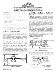
3. Determine your ceiling fan mounting type (Figure 2). Most installations<br />
will be one of these four types: Canopy Hanger, <strong>Hunter</strong> Hands-Free TM<br />
Canopy, Low Profile Styles I and II, or Bracket Hanger.<br />
4. Install the ceiling fan according to its instructions, up to the point of<br />
making the electrical connections. Connect receiver to ceiling fan according<br />
to the mounting type as instructed in Figure 2.<br />
5. If the fan is already installed, turn the power <strong>OFF</strong> at the main electrical<br />
panel. Reverse the installation procedure according to the fan instructions,<br />
to the point of disconnecting the fan wiring. Connect the receiver to the<br />
ceiling fan according to the mounting type as instructed in Figure 2.<br />
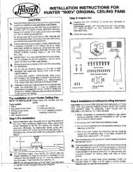
6. Use the 2 large wire nuts supplied to connect the receiver and house<br />
wiring, then use the 3 small wire nuts supplied to connect the receiver and<br />
ceiling fan wiring. Refer to the Wiring Diagram in Figure 3.<br />
7. Be sure the antenna is positioned securely, so it can not interfere with<br />
the ceiling fan motor. Refer to Figure 2. Do not modify or damage the<br />
antenna wire, as control performance may be reduced. After securing the<br />
receiver, antenna, and wiring, finish hanging the ceiling fan according to<br />
its instructions.<br />
Figure 1<br />
Transmitter Back<br />
<strong>Fan</strong> Installation Types:<br />
NOTE: Some fans may have considerable excess lead wire. For easier<br />
canopy installation, cut the excess wire leaving a minimum of 6 inches<br />
remaining. Restrip the fan lead wires 1/2 inch. Place remaining excess wire<br />
into the ceiling electrical box as needed.<br />
Canopy Hanger (Fig. 2-A): Place receiver in canopy. Connect wiring as<br />
shown in Figure 3. Extend antenna through one of the ceiling plate openings<br />
(approximately 3–6˝).<br />
<strong>Hunter</strong> Hands-Free Canopy (Fig. 2-B): Connect wiring as shown in<br />
Figure 3. Place receiver inside mounting bracket. Extend antenna above<br />
the ceiling mounting bracket (approximately 3–6˝).<br />
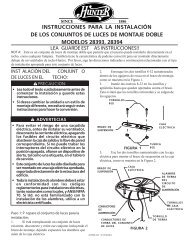
Low Profile Style I (Fig. 2-C): Secure receiver to the fan plate above the<br />
motor with UL listed cable ties (not included). Connect wiring as shown<br />
in Figure 3. Extend antenna through one of the ceiling plate openings<br />
(approximately 3–6˝).<br />
Low Profile Style II (Fig. 2-D): Secure receiver to the ceiling mounting<br />
bracket with UL listed cable ties (not included). Connect wiring as shown<br />
in Figure 3. Extend antenna above the ceiling mounting bracket (approximately<br />
3–6˝).<br />
Antenna<br />
Receiver<br />
Jumpers<br />
1 2 3 4<br />
Canopy Hands-Free TM Canopy Low Profile I Low Profile II Bracket Hanger<br />
Motor<br />
Mounting<br />
Plate<br />
Ceiling<br />
Bracket<br />
Receiver<br />
Antenna<br />
<strong>Fan</strong> Body<br />
Antenna<br />
Fig. 2-C Fig. 2-D Fig. 2-E<br />
12 VOL T<br />
Receiver Back<br />
<strong>ON</strong> DIP<br />
1 2 3 4<br />
Dip Switch<br />
Receiver<br />
Br ac ket<br />
Canopy<br />
Figure 3 Wiring Diagr am<br />
Antenna<br />
Black/<br />
White<br />
<strong>Light</strong><br />
Ki t<br />
Bracket Hanger (Fig. 2-E): Starting with the antenna wire, slide receiver<br />
inside mounting bracket. If a ground wire mounting screw prevents the<br />
receiver from sliding into the bracket, move ground wire and screw to an<br />
unused hole at the top of the bracket or secure with a canopy mounting<br />
screw. The bracket must remain properly grounded. Connect wiring<br />
as shown in Figure 3. Extend antenna above the receiver (approximately<br />
5–8˝).<br />
Cable Tie Routing for Low Profile <strong>Fan</strong>s (Figs. 2-C, 2-D): Insert cable tie<br />
through openings as shown. DO NOT insert the cable<br />
tie through the inside of the receiver. The cable tie<br />
can be placed across the length or width of the<br />
receiver to best match your fan installation type.<br />
TROUBLESHOOTING<br />
Symptom Possible Causes Solution<br />
1. No functions operate.<br />
2. Operates only at close range.<br />
3. Inconsistent operation.<br />
Red White<br />
Fa n<br />
Commo n<br />
Blac k/Hot<br />
White/Neutra l<br />
HUNTER FAN COMPANY C<strong>ON</strong>TROL LIMITED WARRANTY<br />
Main Power not restored. Replace fuse. Turn <strong>ON</strong> circuit breaker. Turn <strong>ON</strong> wall switch.<br />
<strong>Fan</strong> pull chain not set to <strong>ON</strong>.<br />
<strong>Light</strong> pull chain not set to <strong>ON</strong>.<br />
Receiver wiring incorrect.<br />
Transmitter and receiver dip<br />
switches do not match.<br />
Battery too weak.<br />
Signal blocked from reaching<br />
receiver.<br />
Signal partially blocked from<br />
reaching receiver.<br />
Set fan pull chain to the desired speed.<br />
Set light kit to <strong>ON</strong>.<br />
Verify wiring connections.<br />
Set transmitter and receiver to same dip switch setting.<br />
Replace with new, 12 Volt alkaline battery. Refer to Figure 1.<br />
Extend antenna into ceiling box, or move it for better<br />
reception.<br />
Battery too weak. Replace with new, 12 Volt alkaline battery. Refer to Figure 1.<br />
RF interference.<br />
Continuing RF interference.<br />
AC<br />
Po wer<br />
In<br />
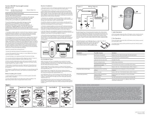
Figure 4<br />
<strong>Fan</strong> <strong>Control</strong><br />
1. <strong>Light</strong> Operation:<br />
Extend antenna into ceiling box, or move it for better<br />
reception.<br />
Turn <strong>OFF</strong> wall switch for 5 seconds, then turn back <strong>ON</strong>.<br />
Change dip switch settings to a different code in both<br />
Transmitter and Receiver.<br />
<strong>Light</strong> Kit <strong>Control</strong><br />
• Press and quickly release the <strong>ON</strong> or <strong>OFF</strong> button on the remote control to<br />
turn the light <strong>OFF</strong> or <strong>ON</strong>. (<strong>Light</strong> will come <strong>ON</strong> at maximum brightness.)<br />
2. <strong>Fan</strong> Operation:<br />
• Press and quickly release the <strong>ON</strong> or <strong>OFF</strong> button on the remote control to<br />
turn the fan <strong>OFF</strong> or <strong>ON</strong>.<br />
• To change the fan speed, slowly pull the fan pull-chain switch to select<br />
the desired speed.<br />
The <strong>Hunter</strong> <strong>Fan</strong> Company makes the following limited warranty to the original purchaser of the <strong>Control</strong> (“<strong>Control</strong>”): Your <strong>Control</strong> is warranted to be free<br />
from defects in material and workmanship for a period of one year from the date of sale. If the <strong>Control</strong> malfunctions or fails within the warranty period<br />
due to a defect in material or workmanship we will replace it free of charge. IF THE ORIGINAL PURCHASER CEASES TO OWN THE C<strong>ON</strong>TROL, THIS WAR-<br />
RANTY AND ANY IMPLIED WARRANTY, INCLUDING BUT NOT LIMITED TO ANY IMPLIED WARRANTY OF MERCHANTABILITY OR FITNESS FOR A PARTICULAR<br />
PURPOSE, ARE VOIDED. THIS WARRANTY IS IN LIEU OF ALL OTHER EXPRESS WARRANTIES. THE DURATI<strong>ON</strong> OF ANY IMPLIED WARRANTY, INCLUDING, BUT<br />
NOT LIMITED TO, ANY IMPLIED WARRANTY OF MERCHANTABILITY OR FITNESS FOR A PARTICULAR PURPOSE, IN RESPECT TO ANY C<strong>ON</strong>TROL, IS EXPRESSLY<br />
LIMITED TO THE PERIOD OF THE EXPRESS WARRANTY SET FORTH ABOVE FOR SUCH C<strong>ON</strong>TROL. This warranty excludes malfunctions or failures which were<br />
caused by repairs by persons not authorized by us, mishandling, improper installation, modifications, or damage to the <strong>Control</strong> while in your possession,<br />
or unreasonable use. This warranty does not apply to batteries or to deterioration or damage to the product caused by the use of faulty batteries. To<br />
obtain a replacement, return your <strong>Control</strong> postage prepaid along with proof of purchase to <strong>Hunter</strong> <strong>Fan</strong> Company Service Department at 2500 Frisco Avenue,<br />
Memphis, Tennessee 38114. IN NO EVENT SHALL HUNTER FAN COMPANY BE LIABLE FOR C<strong>ON</strong>SEQUENTIAL OR INCIDENTAL DAMAGES. SOME STATES<br />
DO NOT ALLOW LIMITATI<strong>ON</strong>S <strong>ON</strong> HOW L<strong>ON</strong>G AN IMPLIED WARRANTY LASTS OR THE EXCLUSI<strong>ON</strong> OR LIMITATI<strong>ON</strong>S OF INCIDENTAL OR C<strong>ON</strong>SEQUENTIAL<br />
DAMAGES SO THE ABOVE LIMITATI<strong>ON</strong>S OR EXCLUSI<strong>ON</strong>S MAY NOT APPLY TO YOU. THIS WARRANTY GIVES YOU SPECIFIC LEGAL RIGHTS AND YOU MAY ALSO<br />
HAVE OTHER RIGHTS WHICH VARY FROM STATE TO STATE.<br />
42715-01 01/17/2007<br />
Printed in China
<strong>Control</strong> <strong>ON</strong>/<strong>OFF</strong> de Ventilador y Luz <strong>Hunter</strong><br />
<strong>Model</strong>o <strong>27157</strong><br />
Capacidad: Ventilador 120 VCA, 60 Hz,1.0 A Peso del receptor: 6 oz.<br />
Lámpara incandescente de 300 Vatios<br />
Lea Y Guarde Estas Instrucciones<br />
Precaución: ¡Riesgo de choque eléctrico!<br />
Todo cableado debe realizarse de acuerdo con los códigos<br />
eléctricos locales y nacionales. Si no está familiarizado<br />
con las normas de cableado, debe emplear un electricista<br />
calificado.<br />
Para evitar el recalentamiento y el posible daño a<br />
otros equipos, no instale la unidad para controlar un<br />
receptáculo, un artefacto de iluminación fluorescente,<br />
un aparato operado por motor o alimentado por<br />
transformador. Úselo sólo para controlar un ventilador de<br />
techo con hojas de paleta y un artefacto de iluminación<br />
incandescente o halógena.<br />
Notas:<br />
1. Este dispositivo cumple con la parte 15 de las reglas FCC. La operación<br />
está sujeta a las siguientes dos condiciones: (1) este dispositivo no puede<br />
causar una interferencia perjudicial, y (2) este dispositivo debe tolerar cualquier<br />
interferencia recibida, incluyendo interferencias que puedan causar<br />
una operación no deseada.<br />
2. Este equipo se ha probado y cumple con los límites para un dispositivo<br />
digital clase B, de acuerdo con la Parte 15 de las reglas FCC. Estos límites<br />
están diseñados para proporcionar una protección razonable contra la<br />
interferencia perjudicial en una instalación residencial. Este equipo genera,<br />
usa y puede radiar energía de radio frecuencia, y si no se instala y usa de<br />
acuerdo con las instrucciones, puede causar interferencia perjudicial a la<br />
comunicación por radio. Sin embargo, no hay garantía de que no pueda<br />
producirse interferencia en una instalación en particular. Si este equipo<br />
causa alguna interferencia perjudicial a la recepción de radio o televisión,<br />
lo que puede determinarse apagando y encendiendo el equipo, el usuario<br />
debe tratar de corregir la interferencia aplicando una o más de las medidas<br />
siguientes:<br />
• Reoriente o reubique la antena receptora.<br />
• Aumente la separación entre el equipo y el receptor.<br />
• Conecte el equipo en una salida de un circuito diferente del circuito en el<br />
que está conectado el receptor.<br />
• Consulte con su representante de ventas o con un técnico experimentado<br />
de radio/TV.<br />
3. Sólo para uso con ventiladores de techo con inversión de rotación, de<br />
1.0 amperio o menos, y con conjuntos de lámparas incandescentes de 300<br />
vatios o menos.<br />
4. No debe usarse con motores de polo sombreado. No se recomienda su<br />
uso con el modelo <strong>Hunter</strong> Original®. Para los ventiladores de la serie <strong>Hunter</strong><br />
Original®, use los controles <strong>Hunter</strong> modelos 22691, 27187, o 27189.<br />
5. Este producto está diseñado para ser utilizado con un solo interruptor.<br />
Si desea utilizar más de un interruptor para controlar la lámpara, consulte<br />
a un electricista calificado.<br />
Cualquiera cambio o modificación a este equipo no aprobado expresamente<br />
por <strong>Hunter</strong> <strong>Fan</strong> Company anulará la autorización del usuario para<br />
operar el equipo.<br />
Antes De Instalar El <strong>Control</strong>:<br />
1. Use el interruptor tirador de cadena para establecer la velocidad del<br />
ventilador a la posición ALTA antes de la instalación.<br />
2. Fije el conjunto de luz del ventilador de techo en la posición <strong>ON</strong> antes<br />
de la instalación. El nivel de iluminación sólo debe cambiarse usando el<br />
control universal.<br />
Instalación Del Receptor:<br />
1. Desconecte la alimentación de energía al ventilador de techo y al<br />
conjunto de luces en el panel eléctrico principal. Retire el fusible o mueva<br />
Figura 2<br />
Suspensión De Campana Campana <strong>Hunter</strong><br />
TM<br />
Hands-Free<br />
Placa de techo<br />
Campana<br />
Antena<br />
Receptor<br />
Placa de techo<br />
Campana<br />
Fig. 2-A Fig. 2-B<br />
Antena<br />
Receptor<br />
Soporte de techo<br />
Motor<br />
del<br />
ventilador<br />
Perfil Bajo Estilo I<br />
Colocacion del<br />
receptor<br />
en el motor<br />
el interruptor automático a la posición de apagado.<br />
panel. Remove fuse or move circuit breaker to the <strong>OFF</strong> position.<br />
2. ¡IMPORTANTE! Antes de instalar este control, verifique los ajustes<br />
predeterminados del puente en el transmisor y en los conmutadores DIP<br />
en el receptor. Vea la Figura 1. Asegúrese que las posiciones del puente del<br />
transmisor y las posiciones del conmutador DIP en el receptor coincidan, o<br />
el ventilador de techo no funcionará. Seleccione combinaciones diferentes<br />
para los conmutadores DIP y los puentes para evitar la operación incorrecta<br />
debido al control remoto de otros ventiladores.<br />
3. Determine el tipo de montaje de su ventilador de techo (Figura 2). La<br />
mayoría de instalaciones será uno de estos cuatro tipos: Suspensión de<br />
campana, Campana <strong>Hunter</strong> Hands-Free TM , Perfil bajo Estilos I y II, o Suspensión<br />
de soporte.<br />
4. Instale el ventilador de techo de acuerdo con sus instrucciones, hasta la<br />
realización de las conexiones eléctricas. Conecte el receptor al ventilador<br />
de techo de acuerdo con el tipo de montaje, como se indica en la Figura 2.<br />
5. Si el ventilador ya está instalado, apague la alimentación en el panel<br />
eléctrico principal. Invierta el procedimiento de instalación de acuerdo con<br />
las instrucciones del ventilador, hasta el punto de desconectar el cableado<br />
del ventilador. Conecte el receptor al ventilador de techo de acuerdo con<br />
el tipo de montaje, como se indica en la Figura 2.<br />
6. Use los 2 empalmes plásticos grandes suministrados para conectar al receptor<br />
con el cableado ya existente, y luego los 3 pequeños para conectar<br />
el receptor y el ventilador de techo. Consulte el Diagrama de cableado en<br />
la Figura 3.<br />
7. Asegúrese que la antena esté ubicada en forma segura para que no<br />
pueda interferir con el motor del ventilador de techo. Consulte la Figura 2.<br />
No modifique ni dañe el alambre de la antena, ya que podría perjudicar el<br />
funcionamiento del control. Después de asegurar el receptor, la antena y el<br />
cableado, termine de suspender el ventilador de techo de acuerdo con las<br />
instrucciones.<br />
Figura 1<br />
Parte Posterior<br />
del Transmisor<br />
Tipos De Instalación De Ventilador:<br />
NOTA: Algunos ventiladores pueden tener un considerable exceso de<br />
conductor. Para una instalación más fácil de la campana, corte el alambre<br />
en exceso dejando un mínimo de 6” (15 cm.) Pele nuevamente los extremos<br />
de los alambres del ventilador 1/2”. Coloque el alambre de exceso<br />
restante en la caja eléctrica de techo según sea necesario.<br />
Suspensión De Campana (Fig. 2-A): Coloque el receptor en la campana.<br />
Conecte los alambres como se muestra en la Figura 3. Extienda la antena<br />
a través de una de las aberturas de la placa de techo (aproximadamente<br />
entre 3” y 6”).<br />
Campana <strong>Hunter</strong> Hands-Free (Fig. 2-B): Conecte los alambres como<br />
se muestra en la Figura 3. Coloque el receptor dentro de un soporte de<br />
montaje. Extienda la antena por encima del soporte de montaje de techo<br />
(aproximadamente entre 3” y 6”).<br />
Perfil Bajo Estilo I (Fig. 2-C): Asegure el receptor a la placa del ventilador<br />
sobre el motor con sujetacables aprobados por UL (no incluidos). Conecte<br />
los alambres como se muestra en la Figura 3. Extienda la antena a través<br />
de una de las aberturas de la placa de techo (aproximadamente entre 3”<br />
y 6”).<br />
Antena<br />
Receptor<br />
Puentes<br />
1 2 3 4<br />
Placa de<br />
montaje<br />
del motor<br />
Perfil Bajo Estilo II<br />
Soporte de techo<br />
Receptor<br />
Antena<br />
Motor del<br />
ventilador<br />
Antena<br />
Fig. 2-C Fig. 2-D Fig. 2-E<br />
12 VOL T<br />
Portacontrol Remoto<br />
<strong>ON</strong> DIP<br />
1 2 3 4<br />
Conmutador DIP<br />
Suspensión De Soporte<br />
Receptor<br />
Soporte<br />
Campana<br />
Figura 3 Diagrama de Cableado<br />
Antena<br />
Negro/<br />
Blanco<br />
Conjunto<br />
de Luz<br />
Rojo<br />
Ventilador<br />
Blanco<br />
Comun<br />
Negro/<br />
Con tension<br />
Blanco/ Neutro<br />
Entrada<br />
de<br />
alimentacion<br />
CA<br />
Perfil Bajo Estilo II (Fig. 2-D): Asegure el receptor al soporte de montaje del<br />
techo con sujetacables aprobados por UL (no incluidos). Conecte los alambres<br />
como se muestra en la Figura 3. Extienda la antena por encima del soporte de<br />
montaje de techo (aproximadamente entre 3” y 6”).<br />
Suspensión De Soporte (Fig. 2-E) : Comenzando con el alambre de la antena,<br />
deslice el receptor dentro del soporte de montaje. Si el tornillo de montaje de<br />
un alambre de tierra evita que el receptor se deslice en el soporte, mueva el<br />
alambre de tierra y atorníllelo en un agujero no utilizado en la parte superior<br />
del soporte o asegúrelo con un tornillo de montaje de campana. El soporte<br />
debe permanecer puesto a tierra adecuadamente. Conecte los alambres como<br />
se muestra en la Figura 3. Extienda la antena encima del receptor (aproximadamente<br />
entre 5” y 8”).<br />
Colocación De Sujetacables Para Ventiladores De Perfil Bajo (Fig. 2-C, 2-<br />
D): Introduzca el sujetacables a través de las aberturas, tal como se muestra.<br />
NO introduzca el sujetacables a través del<br />
interior del receptor. El sujetacables puede colocarse<br />
longitudinal o transversalmente al receptor para<br />
adaptarse mejor al tipo de instalación de su<br />
ventilador.<br />
LOCALIZACIÓN DE FALLAS<br />
Síntoma Causas Posibles Solución<br />
1. No opera ninguna función.<br />
2. Opera sólo en un rango restringido.<br />
3. Operación irregular.<br />
La alimentación principal no se ha<br />
restaurado.<br />
La cadena del ventilador no está<br />
fijada en Alta.<br />
El tirador de la cadena de luz no<br />
está colocado en <strong>ON</strong> (encendido).<br />
Cableado de receptor incorrecto.<br />
Los ajustes del transmisor y el<br />
receptor no coinciden.<br />
Batería demasiado débil.<br />
La señal no puede alcanzar al<br />
receptor.<br />
Batería demasiado débil.<br />
La señal sólo alcanza parcialmente<br />
al receptor.<br />
Interferencia de RF.<br />
Interferencia continua de RF.<br />
GARANTÍA LIMITADA DEL C<strong>ON</strong>TROL DE HUNTER FAN COMPANY<br />
Figur a 4<br />
<strong>Control</strong> de kit de luz<br />
1. Operación de la luz:<br />
• Presione y libere rápidamente el botón de luz en el control de pared para<br />
apagar o encender la luz. (La luz se encenderá con el máximo brillo)<br />
2. Operación Del Ventilador:<br />
• Presione y libere rápidamente el botón de <strong>ON</strong> o <strong>OFF</strong> en el control de<br />
pared para apagar o encender la luz.<br />
• El ventilador empezará en ALTA velocidad. Para cambiar la velocidad del<br />
ventilador, tire suavemente del interruptor de cadena del ventilador para<br />
seleccionar la velocidad deseada.<br />
Reemplace el fusible. Encienda el interruptor automático.<br />
Encienda el interruptor de pared.<br />
Coloque el interruptor de cadena del ventilador en la velocidad<br />
deseada.<br />
Fije el conjunto de luces en <strong>ON</strong>.<br />
Verifique las conexiones del cableado.<br />
Fije el transmisor y el receptor al mismo ajuste.<br />
Reemplace con una batería alcalina nueva de 12 voltios. Consulte la<br />
Figura 1.<br />
Extienda la antena en la caja de techo, o muévala para<br />
obtener una mejor recepción.<br />
Reemplace con una batería alcalina nueva de 12 voltios.<br />
Consulte la Figura 1.<br />
Extienda la antena en la caja de techo, o muévala para<br />
obtener una mejor recepción.<br />
Apague el interruptor de pared por 5 segundos y luego enciéndalo<br />
otra vez.<br />
Cambie los ajustes a un código diferente en el transmisor y<br />
en el receptor.<br />
<strong>Control</strong> de Ventalator<br />
<strong>Hunter</strong> <strong>Fan</strong> Company establece la siguiente garantía limitada al comprador original del <strong>Control</strong> (“<strong>Control</strong>”): Garantizamos que su <strong>Control</strong> no tendrá<br />
defectos en materiales ni mano de obra por un año a partir de la fecha de compra. Si el <strong>Control</strong> presenta un funcionamiento defectuoso o una avería<br />
dentro del período de garantía debido a un defecto en el material o la mano de obra, lo reemplazaremos en forma gratuita. SI EL COMPRADOR ORIGINAL<br />
DEJA DE POSEER EL C<strong>ON</strong>TROL, ESTA GARANTÍA Y CUALQUIER GARANTÍA IMPLÍCITA, INCLUYENDO, PERO SIN LIMITARSE A TODA GARANTÍA IMPLÍCITA<br />
DE COMERCIABILIDAD O ID<strong>ON</strong>EIDAD PARA UN PROPÓSITO PARTICULAR, QUEDA ANULADA. ESTA GARANTÍA SUSTITUYE A TODAS LAS OTRAS GARANTÍAS<br />
EXPRESAS. LA DURACIÓN DE TODA GARANTÍA IMPLÍCITA, INCLUYENDO PERO SIN LIMITARSE A CUALQUIER GARANTÍA IMPLÍCITA DE COMERCIABILIDAD O<br />
ID<strong>ON</strong>EIDAD PARA UN PROPÓSITO PARTICULAR, RELACI<strong>ON</strong>ADA C<strong>ON</strong> CUALQUIER C<strong>ON</strong>TROL, ESTÁ EXPRESAMENTE LIMITADA AL PERÍODO DE LA GARANTÍA<br />
EXPRESA ESTABLECIDA ANTERIORMENTE PARA DICHO C<strong>ON</strong>TROL. Esta garantía excluye funcionamientos defectuosos o fallas causados por reparaciones<br />
realizadas por personas no autorizadas por nosotros, mal uso, instalación incorrecta, modificaciones, o daños al <strong>Control</strong> mientras esté en su posesión, o<br />
por un empleo no razonable. Esta garantía no se aplica a las baterías ni al deterioro o daño al producto causado por el uso de baterías defectuosas. Para<br />
obtener un reemplazo, devuelva su <strong>Control</strong> con el franqueo prepagado junto con una prueba de su compra al Departamento de servicio de <strong>Hunter</strong> <strong>Fan</strong><br />
Company, en 2500 Frisco Avenue, Memphis, Tennessee 38114. EN NINGÚN CASO HUNTER FAN COMPANY SERÁ RESP<strong>ON</strong>SABLE DE DAÑOS PERJUDICIALES<br />
O ACCESORIOS. ALGUNOS ESTADOS NO PERMITEN LIMITACI<strong>ON</strong>ES SOBRE LA DURACIÓN DE UNA GARANTÍA IMPLÍCITA O LA EXCLUSIÓN O LIMITACIÓN<br />
DE DAÑOS ACCESORIOS O PERJUDICIALES, ASÍ QUE LAS LIMITACI<strong>ON</strong>ES O EXCLUSI<strong>ON</strong>ES ANTES MENCI<strong>ON</strong>ADAS PUEDEN NO APLICARSE A USTED. ESTA<br />
GARANTÍA LE DA DERECHOS LEGALES ESPECÍFICOS, PERO USTED TAMBIÉN PUEDE TENER OTROS DERECHOS QUE VARÍAN DE ESTADO A ESTADO.<br />
42715-02 07/19/2007<br />
Impreso en China