SIMPLY - Gate Motors
SIMPLY - Gate Motors
SIMPLY - Gate Motors

Create successful ePaper yourself
Turn your PDF publications into a flip-book with our unique Google optimized e-Paper software.
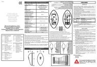
SAFETY CRITERIA ELECTRO LOCK MOTOR POSITION AND ARTICULADED ARM<br />
1 Attention: before beginning any kind of procedure of installation is absolutely Please notice that the electric lock must be installed on the swing that opens first and 1 Put the motor on the anchor plate, pying attention to the exit pin of the motor must<br />
necessary to read all this manuall. must be connected with the terminal board of the control unit. be turned to the interior of the gate.<br />
2 Test/Control that the performances of the actuator auswer to your installation Position of the electric lock: (Fig. B) 2 Put together the three parts of the articulated arm. ( Fig. M)<br />
needs. Position 1: Lock between the wings The upright arm with the arm, and the arm with the clamp S3 with screws T.E.<br />
3 Besides control that: (in this case is necessary to use the bolt RT15 on the second wing). 12x35, self loking huts M12 and wasther Ø 12 mm.<br />
• The gare hinges are in good conditions and perfectly fattened. Position 2: Lock in the floor 3 To unclamp the motor using the normal key. (Fig. L)<br />
• The gate has mechanicall stops in the opening and the closing. (in this case the utilisation of the bolt is not necessary). 4<br />
Remember to remove the lock or at least block the lock in opening position and take<br />
Fit the articulated arm into the motor shaft (picture L) and fix it through the TE bolt<br />
8x16 and the Ø32 washer.<br />
INSTALLATION ADVICE away all the bolts of lock. 5 Extend the articulated arm till to positionate the fixing clamp S3 on the gate.<br />
Connections: The best situation is given when the arm formes a little angle as showing in Fig. C.<br />
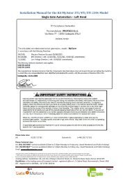
• See the “Operational Diagram ” and refer to the control central scheme. RIGHT OR LEFT ACTUATORS ACTUATORS (Fig. A) 6 To solder up or to screw the clamp S3 to the gate.<br />
• The electric cable in the exit from the actuator must be tight, but do an ample The actuators are supplied in Right or Left version.<br />
curve towards the bottom in order to avoid the reflux in the inside of the actuator Right or left are established looking the gate from the side where the actuators are LIMIT SWITCH REGULATION (fig. R)<br />
itself. (Fig. Q) installed, if the hinges are on the right the actuator is right, if they are on the left the 1 Set the motor thrust<br />
• The adjustment must be effected when the device has no power supply. actuator is left. 2 Give an opening impulse.<br />
• Foresee a omnipolar breaking device near to the apparatus (the contact must Conseguentely the actuator must be installed with the exit pin, positioned in the 3 When the leaves reach the opening mechanichal limit switch it is necessary to<br />
measure at least 3 mm). Always protect the power supply using a 6A automatic hinges of the gates. place the Cam of the micro limit switch and to fix it screwing it down without<br />
switch, or a 16A single-phase switch fises.<br />
forcing.<br />
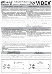
• The power supply lines the motors, to the control unit and the connection lines to DETERMINATION OF FIXING MEASURES 4 Give a closing impulse.<br />
the outfits must be separated to avoid troubles which could generate problems in To determinate the clamping point it is necessary pay attention to this: 5 When the leaves reach the closing mechanichal limit switch it is necessary to put<br />
the installation working. • A = 300 mm (Fig. C) the Cam of the limit switch and fix it by screwing it without forcing.<br />
• Any outfits (of control or safety) eventually connected to the control unit must be Maximum dimension betwen the axis of the gate and the edge of the pillar. 6 Regulate the motor thrust (as per the control unit instructions) It is possible to<br />
tension free. • B = 30 mm (Fig. C) Stop the working stroke of the gate with a force of 150N (about 15 Kg)<br />
Spare parts: Maximum dimension from the anchor plate to the edge of the pillar. N.B. This kind of motor has been studied to be used with micro-limit swith.<br />
• Use esclusively original spare parts. (to avoiod the possible brake of the edge) If you do not use them unclamp the motor can be more difficoult and you could<br />
• The batteries should be put with industril waste and not with domestic refuse . • D = 14 mm (Fig. F) have a more rapid damage of the mechanical parts.<br />
(Law n. 475/88).<br />
Vertical distance from the clamping point of the clamp S3 on the gate, to the<br />
Installation:<br />
anchor plate on the little adge. MECHANICAL STOP (Fig. A)<br />
• In order to use correctlythe product and to exclude the possibility of injury or<br />
At this point you need to position the machanical Stop to proced respectively, to the<br />
damage, refer to the "Generals" page enclosure, which is an integrated part of <strong>Gate</strong> fixed in the middle of the pillar (Fig. D) wing’s closing and opening Stop.<br />
this manual. In this case the maximun al opening corner of the gate is 90° .<br />
• The use of this equipment must be in observance of the safety standards in force <strong>Gate</strong> fixed on the edge pillar (Fig. E)<br />
EXTERNAL OPENING GATE.<br />
in the country where it is installed, as well as the standards governing proper In this case the gate can be opened with a corner greater than 90°. If the gate opens till the exterior it is possible to put the actuator between the two pilar.<br />
installation.<br />
Pay attention to this: growing the distance of the actuator from the edge of the pillar <strong>Gate</strong> fixed in the middle of the pillar (Fig. N)<br />
Warranty:<br />
measure B, the opening angle of the gate grows. In this case the maximun al opening corner of the gate is 90° .<br />
• The warranty supplied by the manufacturer becomes volid in the event of<br />
<strong>Gate</strong> fixed on the edge pillar (Fig. O)<br />
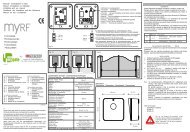
interference, carelessness, improper use, lightening damage, power surges or HEIGHT INSTALLATION (Fig. G) Exterior fixed the pillar (Fig. P)<br />
use by unqualified personnel. Calculate the height of the actuator installation according to the gate's shape and the In this case the gate can be opened with a corner greater than 90° .<br />
• The warranty will also become in the following event: Failure to observe the fastening possibility.<br />
Pay attention to this: reducing the distance of the actuator from the edge of the pillar<br />
instructions given in the manuals supplied with the product. a) If the gate has a big structure you can position it at any highness with no limits. measure A, the opening angle of the gate grows.<br />
The application of any part in a manner differing from that provided for current b) If the structure is light is necessary to put the operator as muca as possible to the<br />
legislation or the use of spare parts which are unsuitable and/or not approved by centre of the gate (in heigt).<br />
RELEASE OF THE ACTUATOR<br />
manifacturer. Position 1 Central beam of the gate - To keep out the cap on the fore part of the motor. (Fig. L)<br />
Position 2 Stiffen of the gate - To put and to wheel of 90° in time sense the endowed key.<br />
INSTALLATION INSTRUCTION SEQUENCE<br />
Not it is possible to open and to close the gatem handly.<br />
1 Before the installation, analyse the risks referring to the chapter “Generalities”<br />
FIXING THE ANCHOR PLATE<br />
- To re-hook the actuator, to wheel in the contrary sense the endowed key.<br />
of this instructions manual, fill the technic table and eliminate the risks noticed. To dawel or to soldel the anchor plate on the little pillar near to the gate, paynig It is not necessary the gate is in a particurety position, because at the first order all the<br />
In case of more risks, foresee the installation with security system.<br />
attention to the quotes indicate above.<br />
volvers are restored.<br />
2 Test the security laws of the “Security Criteria”.<br />
In case of clamping with expanding loose pieces, use metallic loose pieces Ø13 mm<br />
3 Identify the right actuator and left actuator.<br />
and consider that the loose piece has to be positioned at 30/35 mm distant from the<br />
4 Controll all the components.<br />
edge of the little pillar to avoid the possibility of broke.<br />
5 Identify the fixing point on the gate and then on the pillar.<br />
In case of wolling pillar use chemichal loose pieces, or resine loose pieces, or a<br />
6 To lock the “Anchor plate” at the little pillar.<br />
connectly wolled clamp.<br />
7 To lock the gear motor at the “Anchor plate”.<br />
It is possible to use the plate, in two different ways, for right or left actuator, according<br />
8 To unclamp the actuator.<br />
to the particulary exigences. (Fig. H / I)<br />
9 To put the articulated arm.<br />
10 To lock the clamp S3 at the gate.<br />
11 Strech the wires as in the “Operational Diagram ”.<br />
12 Connect the central and all the accessoires<br />
13 Program the radio receptor<br />
14 Program working times<br />
In case of badworking, see the “Anomalies and advises”.<br />
If you do not find any solution call the nearest Assistence centre.<br />
ENGLISH