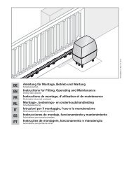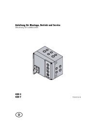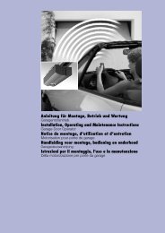
Template BA B168xH238 - Hormann.fr
Template BA B168xH238 - Hormann.fr
Template BA B168xH238 - Hormann.fr

You also want an ePaper? Increase the reach of your titles
YUMPU automatically turns print PDFs into web optimized ePapers that Google loves.
ENGLISH<br />
▶<br />
▶<br />
▶<br />
All persons using the door system must be shown how<br />
to operate it properly and safely.<br />
Demonstrate and test the mechanical release as well as<br />
the safety reversal. To do this, stop the closing door by<br />
grasping it with both hands. The door system must<br />
initiate the safety reversal.<br />
In addition, check that the door is in a flawless<br />
mechanical condition, so that it can be easily operated<br />
by hand and opens and closes properly (EN 12604).<br />
Note:<br />
The fitter must check that the supplied fitting materials are<br />
suitable for the intended application and fitting location.<br />
3.2 Electrical connection<br />
Mains voltage<br />
Danger<br />
Contact with the mains voltage presents the danger of<br />
a deadly electric shock.<br />
For that reason, observe the following warnings under all<br />
circumstances:<br />
▶ Electrical connections may only be made by a qualified<br />
electrician.<br />
▶ The on-site electrical installation must conform to<br />
the applicable protective regulations (230/240 V AC,<br />
50/60 Hz)!<br />
▶ Before performing any work on the operator,<br />
disconnect the mains plug or with direct wiring<br />
(see section 3.2.1) turn off the system power and<br />
prevent it <strong>fr</strong>om being switched on again in accordance<br />
with the safety regulations.<br />
ATTENTION<br />
External voltage at the connecting terminals<br />
External voltage at the connecting terminals of the control<br />
will destroy the electronics.<br />
▶ Do not apply any mains voltage (230/240 V AC)<br />
to the connecting terminals of the control.<br />
To prevent malfunctions:<br />
▶ Duct the operator's connection cables (24 V DC) in an<br />
installation system that is separate <strong>fr</strong>om other supply<br />
lines (230 V AC).<br />
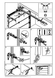
3.2.1 Mains voltage<br />
If needed, instead of the mains cable a fixed connection with<br />
230/240 V AC, 50/60 Hz via an all-pole mains isolator switch<br />
with the appropriate pre-fuse can be used. Order <strong>fr</strong>om left<br />
to right = N, PE, L (see Figure 1.2).<br />
3.3 Connecting additional components to the<br />
circuit board<br />
To connect additional components, the flap of the control<br />
housing must be opened (see Figure 1.1). The terminals used<br />
to connect the radio receiver or additional components such<br />
as internal push buttons or safety equipment such as<br />
photocells, only have a safe low voltage of max. 30 V DC.<br />
All connecting terminals can be given multiple assignments,<br />
but with a maximum of 1 x 2.5 mm 2 (see Figure 2). The mains<br />
plug must always be disconnected before connecting.<br />
Note:<br />
The voltage of approx + 24 V available at the connecting<br />
terminals cannot be used to power a light!<br />
3.3.1 Connecting jack for extensions *<br />
System jack for extensions, e.g. option relay for<br />
warning lamp *.<br />
3.3.2 Connecting an additional external radio<br />
receiver *<br />
In addition to, or instead of, an integrated radio module<br />
(see section 5.5.1), an external radio receiver can be<br />
connected:<br />
• 1-channel radio receiver for the function impulse<br />
operation.<br />
• 2-channel radio receiver for the functions impulse<br />
operation and operator light on / off<br />
• 3-channel radio receiver for the functions impulse<br />
operation, operator light on / off, partial opening<br />
Insert the plug of the receiver in the corresponding slot<br />
(see Figure 4).<br />
3.3.3 Internal push button *<br />
Internal push buttons are connected to the terminals on<br />
the left as shown in Figure 5-7.<br />
• Type IT1 for the function impulse operation (see Figure 6)<br />
• Type IT1b for the function impulse operation<br />
(see Figure 5)<br />
• Type IT3b for the functions impulse operation<br />
(see Figure 7), operator light on / off (see Figure 7.1),<br />
radio operation is prevented (= holiday function,<br />
see Figure 7.2).<br />
3.3.4 Connection for 2-wire photocell *<br />
2-wire photocells (e.g. EL101, EL301) which are used as<br />
safety photocells and to monitor the automatic timer must<br />
be connected as shown in Figure 8 (observe DIL switch 4<br />
setting, section 4.3.3).<br />
Note:<br />
When fitting a photocell, make sure that the transmitter and<br />
receiver housings are fitted as close to the floor as possible –<br />
see the instructions for the photocell.<br />
3.3.5 Emergency battery HNA 18 *<br />
▶ Connect the emergency battery, as displayed in<br />
figure 9.1a.<br />
To enable door movement in the event of a mains failure, an<br />
optional HNA 18 emergency battery can be connected. In the<br />
event of a mains failure, the system automatically switches to<br />
battery operation. During battery operation, the operator light<br />
remains switched off.<br />
* Accessory, not included as standard equipment!<br />
24 TR10A073-B RE / 02.2012