Choisir le cycle de soudage ou pour le MIG(voir explications sur les cycles page 14). Choisir le mode synergique ou manuel :• en mode manuel, le potentiomètre rouge règle la vitesse de fil, lepotentiomètre bleu la tension de soudage.• le mode synergique permet de trouver plus rapidement des paramètrescorrects pour le cas d’application considéré. En effet, la position milieu dubouton bleu de hauteur d’arc correspondra, dans ce mode, à un réglageoptimisé pour la vitesse de fil choisie (bouton rouge). Ce dernier est alors leseul réglage à modifier. Select the or welding cycle for MIG welding (seeexplanations on cycles, page 14). Select the or synergetic or manual mode :• in manual mode, the red potentiometer adjusts : the wire speed, the bluepotentiometer adjusts the welding voltage.• the synergetic mode enables one to locate the correct parameters for therelevant application more quickly. In fact, the middle position of the blue buttonat arc height will, in this mode, correspond to optimized adjustment for theselected wire speed (red button). The latter is then the only adjustment to bemodified. Assurez-vous que le sélecteur GENE ou CAD soit en position GENE Make sure that the GENE or CAD Selector is in GENE position Régler la vitesse de fil (bouton rouge sur le dévidoir). Adjust the wire speed (red button on the wire feed unit). Régler la tension de soudage (bouton bleu sur le dévidoir) ou lepositionner en position centrale. Adjust the welding voltage with the blue button on the wire feed unit or setit to central position.NOTA : Il est possible de connecter une commande à distance sur le dévidoir, dans cecas, basculer l’interrupteur repéré 6 (position située entre les deux boutons de réglagevitesse fil et hauteur d’arc sur le dévidoir). Les deux potentiomètres du dévidoirdeviennent alors inactifs. ( voir dépliant FIGURE 6 à la fin de la notice)Lorsque l’on débranche la CAD et que le commutateur repéré 6 est en position, lesconsignes soudage sur les afficheurs indiquent 000. Pour retrouver les réglagesbasculer l’interrupteur.Afin de faciliter le réglage et de le rendre plus fin, la plage de hauteur d’arc, accessibleavec le bouton bleu, est optimisée en fonction de la nature du gaz, du fil et dudiamètre de fil. La position centrale du bouton équivaut à un meilleur réglage du filchoisi.Il reste ensuite à affiner le réglage autour de la position milieu.Certains cas d’application (exemple : fil aluminium) peuvent nécessiter un décalageplus important par rapport à la position centrale du bouton bleu.L ’afficheur supérieur indique alors la valeur du réglage : de courant de soudage (pré-affichage), bouton 1 en position A de l’épaisseur des tôles à souder, bouton 1 en position – épaisseur de la vitesse de dévidage de fil en m/mn bouton 1 en m/mnL’afficheur du bas indique la tension de soudage.En soudage MIG MAG courant lisse, ajuster le potentiomètre 9 enposition milieu (pour une fusion plus dynamique tourner vers le mini -,pour une fusion plus douce tourner vers le maxi +NOTE : It is possible to connect a remote control to the wire feed unit; in this case,switch over Switch n° 6 (position between the two wire speed adjustment and archeight buttons on the wire feed unit). Both potentiometers of the wire feed unit thenbecome inactive. ( see fold-out FIGURE 6 at the end of this notice)When one disconnects the CAD and when Switch n° 6 is in position, the weldingsettings on the display units show 000. To return to the adjustments, switch the Switchback.To make this last adjustment easier and more fine, the arc length range, available withthe blue button, is optimised depending on gas, wire type and diameter. The middleposition of the button indicates the best adjustment corresponding to the wire used.It’s the enough to fine tune the adjustment around this middle position.Some applications (example : aluminium wires) may need a more specialisedadjustment, furthest from the middle position of the blue button.The upper display-unit then shows the adjustment value : of welding current (pre-display), button 1 in position A of the thickness of the sheet metal to be welded, button 1 in position –thickness of the wire feed speed in m/mn, button 1 in m/mnThe bottom display-unit shows the welding voltage.In smooth current MIG MAG welding, set potentiometer 9 on the middleposition (for more dynamic melting, turn towards the min. -, for softermelting, turn towards the max. +6. CHOIX DES CYCLES DE SOUDAGE 6. WELDING CYCLES SELECTION( voir dépliant FIGURE 8 à la fin de la notice) (see fold-out FIGURE 8 at the end of the manual)1 PREGAZ / PREGAS 2 POST GAZ / POST GASEn MIG-MAG, l’appui sur la gâchette de la torche a des effets différents selon le cycle(ou le mode) de soudage utilisé. Le choix du cycle se fait par les boutons situés enface avant du générateur, en haut. Cycle 2 tempsIn MIG-MAG welding, pressing the trigger of the torch has different effects, dependingon the cycle or welding method used. The cycle is selected by means of the buttonslocated on the front panel of the power source, on the top area. 2-action cycleDans ce mode, l’appui sur la gâchette provoque le dévidage, le prégaz etl’établissement du courant de soudage. Lorsque l’on relâche la gâchette, lesoudage s’arrête. Cycle 4 tempsLe 1 er appui sur la gâchette enclenche le PRE-GAZ.Lorsque la gâchette est relâchée on démarre le soudage (dévidage + courant).Un nouvel appui stoppe le soudage mais le gaz continue de s’écouler.Le dernier relâchement de la gâchette stoppe le POST-GAZ.In this mode, pressing the trigger causes the wire feed, the pregas and theestablishment of the welding current. When the trigger is released, weldingstops. 4-action cyclePRE-GAS is activated the first time the trigger is pressed.When the trigger is released, welding starts up (wire feed + current).Pressing the trigger again stops the welding but the gas continues to flow.Releasing the trigger a final time stops the POST-GAS.C - 14<strong>OPTIPULS</strong> <strong>350</strong> I / <strong>OPTIPULS</strong> <strong>380</strong> I W
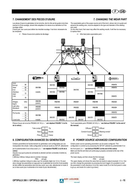
7. CHANGEMENT DES PIECES D'USURE 7. CHANGING THE WEAR PARTLes pièces d'usure du générateur et de la torche, dont le rôle est de guider et de faireavancer le fil de soudage, doivent être adaptées à la nature et au diamètre du fil desoudage utilisé.D'autre part, leur usure peut altérer les résultats soudage. Il est donc nécessaire deles remplacer.The expendable parts of the power-source and of the torch, whose role is to guide andadvance the welding wire, must be adapted to the type and diameter of the weldingwire used.On the other hand, their wear may affect the welding results. It will then be necessaryto replace them. Pièces d'usure de la platine de dévidage : Wire feed plate expendable parts :AcierNormal 0,6 9161-7001 9161-7001 9159-5735Steel 0,8 9161-7006 9161-7002 9161-7002 9159-5730Inox 1,0 9161-7015Stainlessmetallic 9161-7003 9161-7004 9161-7003steel 1,29161-7004CrNi9159-57311,6Alliages 1,0/1,2 9162-0199légers(plastic)Light alloyAluminium 1,2/1,6 9162-0200(plastic)9162-0188 9162-0201 9162-0188 9162-02039162-0189 9162-0202 9162-0189 9162-0204Fils fourrés 1,0 9159-57301,2 9161-70061,4 9161-7011 9161-7015 9161-7011 9159-5731Cored wire 1,6 metallic 9161-7012 9161-7017 9161-7012Pièces d'usure de la torche PROMIG 341 W ( voir dépliant FIGURE 7 à la finde la notice) :Torch expendable parts PROMIG 341 W (see fold-out FIGURE 7 at the end ofthe manual) :Tube contact 1 Tip Diffuseur 4 DiffuserBuse 2 Nozzle Conduit d’usure 5 Wearing conduitPince 3 Clamp Ecrou 6 Nut8. CONFIGURATION AVANCEE DU GENERATEUR 8. POWER SOURCE ADVANCED CONFIGURATIONCertains paramètres de fonctionnement du générateur sont configurables par unemanipulation très simple. Cette configuration se fait par accès au SETUP, sélectionnépar le potentiomètre 6 de la face avant. ( voir dépliant FIGURE 2 à la fin de lanotice)Assurez-vous que la prise de commande du dévidoir soit bien connectée à l'arrière dugénérateur.L'afficheur inférieur indique alors le premier message.PRG pré-gazL'afficheur supérieur indique la valeur que l'on souhaite régler (ex: 0,2 s). On peutalors changer les paramètres en appuyant sur la gâchette de la torche (il est possiblede faire défiler les paramètres dans les deux sens, pour cela, sélectionner le mode 2tsur la face avant pour incrémenter et le mode 4t pour décrémenter).Certain power source operating parameters can be easily configured. Thisconfiguration is carried out by accessing the SETUP; selected by potentiometer 6 onthe front panel. ( see fold-out FIGURE 2 at the end of this notice)Make sure that the wire feed unit control plug is properly connected at the rear of thepower source.The lower display unit then shows the first message.PRG pre-gasThe upper display unit shows the value that one wants to adjust (example: 0.2 s). Onecan then change the parameters by pressing the torch trigger (it is possible to scrollthe parameters in both directions; to do this, select mode 2t on the front panel in orderto go up, and mode 4t in order to go down).<strong>OPTIPULS</strong> <strong>350</strong> I / <strong>OPTIPULS</strong> <strong>380</strong> I W C - 15