Manual TTT CI 8000(27-3-12) - Fagor Electrónica
Manual TTT CI 8000(27-3-12) - Fagor Electrónica
Manual TTT CI 8000(27-3-12) - Fagor Electrónica
- No tags were found...

You also want an ePaper? Increase the reach of your titles
YUMPU automatically turns print PDFs into web optimized ePapers that Google loves.
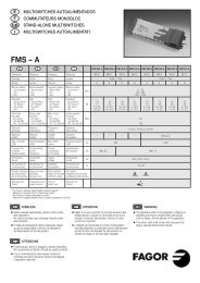
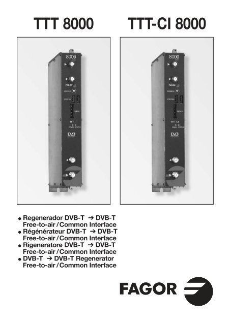
<strong>TTT</strong> <strong>8000</strong> <strong>TTT</strong>-<strong>CI</strong> <strong>8000</strong>● Regenerador DVB-T ➔ DVB-TFree-to-air / Common Interface● Régénérateur DVB-T ➔ DVB-TFree-to-air / Common Interface● Rigeneratore DVB-T ➔ DVB-TFree-to-air / Common Interface● DVB-T ➔ DVB-T RegeneratorSAFree-to-air / Common InterfaceATV
4<strong>12</strong>310■ Inserción CAM y tarjetaInsertion CAM et carteCAM and card insertionInserimento CAM e carta7562448916917935CONTROLES RF1. Entrada2. Salida lazo de entradaRF3. Dirección lógicadel equipo4. Bus de comunicacionesy control5. Bus de alimentación6. Led de control de estado7. Led de comunicaciones8. Salida canal RF COFDM9. Entrada lazo salida RF10. Inserción del módulo CAMCOMMANDES RF1. Entrée2. Sortie bouche entréeRF3. Direction logiqueéquipement4. Bus de communicationet commanda5. Bus d’alimentation6. LED de contrôle d’état7. LED de communication8. Sortie canal RF COFDM9. Entrée boucle sortie RF10. Insertion du module CAMRF CONTROLS1. Input2. RF input loopoutput3. Unit logical address4. Communication andcontrol bus5. Supply bus6. Status control LED7. Communication LED8. COFDM RF outputchannel9. RF output loop input10. CAM module insertionCONTROLLI RF1. Ingresso2. Uscita anello ingressoRF3. Direzione logicaapparecchiatura4. Bus di comunicazionee control5. Bus di alimentazione6. Led di controllo di stato7. Led di comunicazione8. Uscita canale RF COFDM9. Ingresso anello uscita RF10. Inserimento della CAM■ Características principalesCaracterístiques principalesMain specificationsCaratteristiche principaliE F UK I <strong>TTT</strong> <strong>8000</strong> / <strong>TTT</strong>-<strong>CI</strong> <strong>8000</strong>ENTRADA ENTRÉE INPUTS INGRESSIFrecuencia Fréquence Frequency Frequenza 177,5 ÷ 858 MHzNivel de entrada Niveau d’entrée Input level Livello di ingresso 40 ÷ 90 dBμVPérdidas de pasode entradaPertes de passaged’entréeInput step losses Perdite di passaggiodell'ingresso–0,5 ÷ +1 dBMínimo nivel de entradapara 6 módulos en cascadaNiveau minimum d'entréepour 6 modules en cascadeMinimum input level for 6modules in cascadeLivello minimo di ingressoper 6 moduli in cascataDVB-T > 45 dBμVTipo de modulación Type de modulation Modulation type Tipo di modulazione COFDMTRATAMIENTO TRAITEMENT PROCESSING PROCESSINGAcceso condicional Conditional Access Conditional Access Accesso condizionato DVB-<strong>CI</strong> EN50221Inserción LCN Insertion LCN LCN Insertion Inserzione LCN YesSALIDA SORTIE OUTPUTS US<strong>CI</strong>TAFrecuencia Fréquence Frequency Frequenza 50,5 ÷ 858 MHzNivel de salida Niveau de sortie Output level Livello d’uscita 65 ÷ 80 dBμVModo DVB-T Mode DVB-T DVB-T Mode Modo DVB-T 2K, 8KTipo de modulación Type de modulation Modulation type Tipo di modulazione QPSK, 16 QAM, 64 QAMCode Rate Code Rate Code Rate Code Rate 1/2, 2/3, 3/4, 5/6, 7/8Intervalo de guarda Intervalle de Garde Guard Interval Intervalo di guardia 1/4, 1/8, 1/16, 1/32MER salida de RF MER Sortie de RF RF output MER MER Uscita RF 38 dBTipo de modulación Type de modulation Modulation type Tipo di modulazione COFDMGENERAL GÉNÉRAL GENERAL GENERALITemperatura defuncionamientoTempérature defonctionnementOperatingtemperatureTemperatura difunzionamento0 ÷ 45 ºCProgramación Programmation Programming Programmazione UCF 300/PC & MCU <strong>8000</strong>/PC & LPU <strong>8000</strong>Consumo Consommation Consumption Consumo 10 W2
■ EJEMPLO DE APLICA<strong>CI</strong>ÓNEXEMPLE D’APPLICATIONAPPLICATION EXAMPLEESEMPIO DI APPLICAZIONEHousing mountingRack Mounting21441348 214251SHA <strong>TTT</strong> <strong>TTT</strong> <strong>TTT</strong> <strong>TTT</strong> STT STT SPS SAC <strong>TTT</strong> <strong>TTT</strong> <strong>TTT</strong> <strong>TTT</strong> STT STT SPS6 5 4 3 2 16 5 4 3 2 1IN <strong>27</strong> 65IN 3IN 4109- Plano de agujeros para el cofre- Piercing diagramme of the housing- Diagramme de perçage du boîtier- Plane fori per la cassettaNº E F UK I Housing Rack 19”1 Regenerador Regenerateur DVB T - DVB T RigeneratoreDVB T - DVB T DVB T - DVB T Regenerator DVB T - DVB T08290 / 0829<strong>12</strong> Amplificador SHA <strong>8000</strong> Amplificateur SHA <strong>8000</strong> SHA <strong>8000</strong> amplifier Amplificatore SHA <strong>8000</strong> 35083Amplificador SAC <strong>8000</strong> Amplificateur SAC <strong>8000</strong> SAC <strong>8000</strong> amplifier Amplificatore SAC <strong>8000</strong> 350813 Bus de alimentación Bus d’alimentation Supply bus Bus di alimentazione 838074 Fuente de alimentación SPS Alimentation SPS Power supply SPS Fonte di Alimentazione SPS 6<strong>8000</strong>5 Carga F, 75 Ω Charge F, 75 Ω F load, 75 Ω Carico F, 75 Ω 840116 Puente RF Pont RF RF bridge Ponte RF 83814– Unidad de control UCF 300 Unité de contrôle UCF 300 UCF 300 control unit Unitá di controlo UCF 300 851157 Bastidor pared Châssis mural Wall frame Panello a muro 83805 –8 Bastidor Rack 19” 6U Châssis Panier 19” 6U 19” 6U rack frame Panello Rack 19” 6U – 838009 Carátula adaptación Façade adaptation 19” source adaptation Maschera adattamentofuente 19” alimentation 19” front panel fonte 19”– 8380410 Carátula adaptación Façade adaptation 19” module adaptation Maschera adattamentomódulo 19” module 19” front panel modulo 19”– 83802– Cofre con bastidor Coffre avec châssis Howsing with frame Armadio con panelloy aireación et aération and fan e ventilazione– Unidad de Unité d’aération Rack ventilation Unità di ventilazioneaireación Rack Panier unit Rack11 Ventilador VNT 800 para Ventilateur VNT 800 pour Fan VNT 800 for Wall Ventilazione VNT 800 perBastidor BST 807 Châssis mural BST 807 frame BST 807 panello BST 80783806 –– 8380183818 –3
E■ DESCRIP<strong>CI</strong>ÓN● Regenerador de señal DVB-T en DVB-T Free-to-Air(<strong>TTT</strong> <strong>8000</strong>) y con Acceso Condicional DVB-<strong>CI</strong> (<strong>TTT</strong>-<strong>CI</strong> <strong>8000</strong>).Admite señales de entrada en COFDM regenerandoel contenido para conseguir un MER óptimo en el canalCOFDM de salida. Los servicios con derechos de suscripciónserán abiertos por el módulo de acceso condicional (CAM)(<strong>TTT</strong>-<strong>CI</strong> <strong>8000</strong>). La señal de entrada podrá ser cambiada defrecuencia en la banda de RF entre 50.5 y 858 MHz.Gestiona señales MPEG-2 o MPEG-4 permitiendo haceruna selección de los programas que entrega en su salida.■ INSTALA<strong>CI</strong>ÓN Y PUESTA EN MARCHA- Las conexiones y desconexiones de los módulos serealizarán con la fuente de alimentación desconectadade la red.● Insertar la CAM y la tarjeta correspondiente en elequipo (ver ranura de inserción en el número 10 de lapágina 2) antes de colocarlo en el bastidor (<strong>TTT</strong>-<strong>CI</strong> <strong>8000</strong>).● Conectar la toma de tierra del bastidor a la tierra de lainstalación de la antena.● Sujetar los módulos en el bastidor según el ordenindicado en el ejemplo de aplicación, (ver pag 3).Fuente de alimentación a la derecha y amplificadora la izquierda del conjunto.● Realizar la distribución de señal de la(s) antena(s) medianteel puente coaxial F-F (Ref. 83814) y cargar la(s) salida(s)libre(s) con 75 Ω (Ref. 84011).● Unir las Salidas de Canal RF (8) mediante el puentecoaxial F-F, y cargar con 75 Ω la salida libre del módulo 1,junto a la Fuente de alimentación.● Conectar el Bus de Alimentación BA 807 ref. 83807entre los módulos (5) y la Fuente de alimentación SPS.● Conectar los cables de bajada de las antenas en lasentradas correspondientes (1).● Conectar la Fuente de alimentación a la red eléctrica.■ TEMPERATURA DE FUN<strong>CI</strong>ONAMIENTO● Los módulos deben ser refrigerados para funcionarcorrectamente. Para ello es necesario que los módulos semonten en el cofre ventilado (Ref. 83806) o cuando elmontaje sea en rack 19’’ utilizar la unidad de ventilación(Ref. 83801). Cuando son pocos módulos se puede usarel VNT 800 (Réf. 83818). (Ver Fig.1).■ PROGRAMA<strong>CI</strong>ÓN DE LOS MÓDULOSLos módulos permiten estos tipos de programación:● Mediante la unidad de control UCF 300 (Ref 85115),en modo local, siguiendo los pasos que se muestran eneste manual.● Mediante PC, en modo local. Para ello, es necesariodisponer de un módulo MCU <strong>8000</strong> / LPU <strong>8000</strong> y de lainterface «<strong>8000</strong> series» instalada en el PC.■ UCF 300: FUN<strong>CI</strong>ONES DE LAS TECLAS● Las teclas ❏ ▲ ❏▼ permiten el desplazamiento verticalpor el menú.a) En el menú de programación permiten seleccionarla función a programar.b) Dentro de una función permiten seleccionar unparámetro.4c) Dentro de un parámetro programable, permitenmodificar su valor.● Las teclas permiten el desplazamiento horizontalpor el menú de programación, p.ej.:Función parámetro valor.● La tecla avanza hacia la derecha.● La tecla sale sin modificar el valor: escape● La tecla OK valida el dato programado.■ INDICA<strong>CI</strong>ONES EN EL DISPLAY● La unidad de control UCF 300 dispone de dos filas decaracteres alfanuméricos, el modo de displayar los datosjunto con el diagrama de programación de la página 8nos guían en el proceso:● Cuando los caracteres están todos en mayúsculasy en la fila superior indican que estamos en una delas funciones.● Cuando aparecen datos en dos filas del display:estamos viendo el parámetro a ajustar.● La flecha derecha indica cómo entrar a modificar elvalor del parámetro.●❏ ▲ ❏ ▼ ❏ ▼❏❏ ▲ ▼❏ ▲❏ ▼ ❏ ▼❏ ▼❏ ▲Un cuadradito parpadeando indica que podemosmodificar el valor del parámetro con las teclas ❏ ▲ ❏ ▼(para validar pulsar la tecla OK ).● Un signo “+” seguido del nombre del servicio, indicaque ese servicio está en el Multiplex de salida.● Un signo “ * ” delante del nombre indica sevicioencriptado.■ PROGRAMA<strong>CI</strong>ON con UCF 300● Conectar la UCF 300 al módulo deseado, después deunos segundos el equipo presenta el modelo del quese trata: <strong>TTT</strong> <strong>8000</strong> / <strong>TTT</strong>-<strong>CI</strong> <strong>8000</strong>.● Pulsando la tecla entramos en las funciones delmenú standard (menú extendido pulsando OK 3 seg)de programación:1. DVB-T INPUT2. RF OUTPUT3. DVB-T OUTPUT (menú extendido)4. OUTPUT SERVICES5. PSI EDIT (menú extendido)6. CAM (menú extendido) / (solo <strong>TTT</strong>-<strong>CI</strong> <strong>8000</strong>)7. MEMORY● Pulsando las tecla ❏ ▲ ❏▼ nos desplazamos por lasfunciones.● Pulsando la tecla entramos en los parámetrosde la función deseada.Ver diagrama de programación pag. 8.1. DVB-T INPUT1.1. IN Frequency: Frecuencia de entrada:177.5 ÷ 858 MHz.1.2. * Auto Mode: Transfiere los mismos valores de laseñal de entrada en la salida.1.3. * S/N, Modulation, C-BER, DVB-T Mode,QAM MODE, Code Rate, Guard intervaly Bandwidth son informaciones sobre lascaracteristicas de la señal de entrada.* Datos disponibles sólo cuando el tuner está sincronizado.
2. RF OUTPUT: Salida de RF2.1. Out Frequency: Frecuencia de Salida:50,5 ÷ 858 MHz.2.2. Out Level: Nivel de salida: 65 ÷ 80 dBμV.2.3. Out RF: Des/activa la salida de RF.3. DVB-T OUTPUT: Salida DVB-T3.1. DVB T Mode: 2K, 8K.3.2. QAM Mode: QPSK, 16 QAM, 64 QAM.3.3. Code Rate: FEC 1/2, 2/3, 3/4, 5/6, 7/8.3.4. Guard Interval: 1/4, 1/8, 1/16, 1/32.3.5. Bandwidth: 6, 7, 8 MHz.3.6. IQ mode: normal, Invertido.4. OUTPUT SERVICES: Servicios a la salida- Esta función solo será visible cuando el tuner estésincronizado.4.1. List of Services: lista de servicios.● Pulsar para ver la lista.● Pulsar ❏ ▲ ❏▼ para seleccionar el servicio.● Pulsar para entrar en los parámetros del servicio.– Un signo "+" seguido del nombre del servicio, indica queese servicio esta en el Multiplex de salida.– Un signo " * " delante del nombre indica sevicio encriptado.4.1.1. Active: activa el servicio en el MUX de salida.(seleccionar con ❏ ▲ ❏▼ y pulsar OK ).4.1.2. LCN: permite asignar un LCN (Logical Channel Number)entre 1 y 999 a los servicios presentes en la salida(seleccionar con ❏ ▲ ❏ ▼ y pulsar OK ; 000 equivalea NO LCN).❏ ▼ ❏ ▼- Es necesario que NIT Mode esté programado en “Local”.Ver punto 5.1.4.1.3. Program Number: informa del PN del servicio.4.2. Output MUX BW: informa del % total ocupadodel MUX de salida.- No es recomendable trabajar con el MUX BW de salidasuperior al 80% ya que los servicios varían su Bitrate durantela transmisión. (Output MUX BW > 100% : LED de estadoen ambar).4.3. Active all: activa todos los servicios presentes en laentrada,en la salida DVB-T. “pulsar OK ”.- Con servicios encriptados existe la posibilidad de superarel límite de procesado de la CAM.4.4. Read Services: lee los servicios deltranspondedor. “pulsar OK ”.5. PSI EDIT: permite la configuración de la NIT de salida.5.1. NIT Mode: Pass-Through /LOCAL. Si se selecciona"Local", se permite modificar los siguientes parámetros.5.2. Network Name: permite dar un nombre a la red.5.3. Network ID: identificador de red: 0 ÷ 65535(dar el mismo valor que el Orig Network ID).5.4. TS ID: identificador de Transport Stream: 0 ÷ 65535.Algunos receptores de DVB-T necesitan que el TS IDsea diferente por cada módulo memorizado.5.5. Orig. Net. ID: identificador de la Red Origen:0 ÷ 65535. Configuración por país según tabla 3.5.6. Vr. NIT: versión de la tabla NIT: 0 ÷ 31.(solo <strong>TTT</strong>-<strong>CI</strong> <strong>8000</strong>).5.7. Vr. SDT: versión de la tabla SDT: 0 ÷ 31.(solo <strong>TTT</strong>-<strong>CI</strong> <strong>8000</strong>).6. CAM: Acceso al menú MMI de la CAM.(solo <strong>TTT</strong>-<strong>CI</strong> <strong>8000</strong>)6.1. Read MMI: abre la sesión con el MMI (pulsar OK ).Esta opción está disponible si la sesión no está abierta.Si la sesión se abre, devuelve el menú inicial.6.2. Close MMI: cierra la sesión con el MMI. (pulsar OK ).Para un correcto funcionamiento, se recomienda cerrarla sesión al terminar el acceso a los menús del MMI.6.3. Menu MMI: lista de opciones o información de la CAM.Puede aparecer una primera línea de información seguidade una lista de opciones precedidas por un número.(para seleccionar una opción utilizar las teclas ❏ ▲ ❏ ▼y pulsar OK ). La última opción (0. Quit) pasa al menúanterior. Si la información a mostrar es mayor que lalongitud del display, pulsando puede acceder al restodel texto. Una vez enviada la opción seleccionada almódulo, éste devolverá una nueva lista de opcioneso una solicitud de datos.6.4. MMI Enquiry: solicitud de datos por la CAM(ej: introducir un PIN). Para introducir los datos requeridos,utilizar el parámetro del punto 6.5.6.5. Enter User Input: introducción de datos a la CAM.❏ ▼7. MEMORY: Memoria- Memorización automática: después de 30 minutosdesde la última tecla pulsada, los datos actuales sememorizarán en el modulo.7.1. Save Configuration: memoriza la programación actual.7.2. Restore Configuration: permite recuperar laconfiguración memorizada en el equipo.7.3. Save Configuration, Device to UCF 300:Guarda la configuración memorizada con un nombreidentificador en una de las 26 memorias de la Unidad deControl UCF 300.7.4. Load Configuration, UCF 300 to Device:recupera los datos de una memoria del UCF 300 condatos grabados de un <strong>TTT</strong> para ser clonados en otro<strong>TTT</strong> <strong>8000</strong>.E5
E■ AJUSTE DE NIVELES RF1. Extraer el puente coaxial de la Salida de CanalRF (8) del modulo 1º junto a la Fuente de alimentación.2. Ajustar el nivel de salida a 75 dBμV, medianteUCF 300 (Ver punto 1.2 Programación).3. Conectar de nuevo el puente coaxial de 75 Ω.4. Midiendo en la salida del Amplificador SHA ó SAC,regular los niveles de los demás módulos, para lograrecualizarlos al nivel del módulo 1º ya regulado.5. Regular la ganancia del Amplificador, teniendo en cuentael nivel máximo de su salida y la reducción en funcióndel número de canales de la instalación, según Tabla 1.Tab. 1Nº de canalesCOFDM2 4 5 6 8 16 24 32 64Reducción nivelmax. de salida 3 6 7 8 9 <strong>12</strong> 16 15 18(dB)■ FUN<strong>CI</strong>ONES DE LOS LEDS● Led de estado:● Color Verde: OK.● Color Ambar: Problemas con la señal.– Tuner no sincronizado.– Programa no encontrado.– BW de salida excedido > 92%.– Output RF: OFF.– CAM no detectada (sólo en módulos <strong>TTT</strong> <strong>8000</strong> <strong>CI</strong>).● Color Rojo: Equipo averiado● Led de Comunicaciones: Ambar: a la espera de datos.■ PREGUNTAS FRECUENTES● ¿Cuántos programas caben en un Canal de RF,COFDM, UHF, 8 MHz?La capacidad del canal de salida se mide en MBsy hay una relación directa de:● Modulación: QPSK < 16 QAM < 64 QAM● Code Rate FEC:1/2 < 2/3 < 3/4 < 5/6 < 7/8● Intervalo de guarda IG: 1/4 < 1/8 < 1/16 < 1/32(máxima capacidad en negrita)DVB-T (8MHz)Bitrate (Mbps)Modulación Code Rate Tu = 1/4 Tu = 1/8 Tu = 1/16 Tu = 1/321/2 4,98 5,53 5,85 6,032/3 6,64 7,37 7,81 8,04QPSK 3/4 7,46 8,29 8,78 9,055/6 8,29 9,22 9,76 10,057/8 8,71 9,68 10,25 10,561/2 9,95 11,06 11,71 <strong>12</strong>,062/3 13,<strong>27</strong> 14,75 15,61 16,0916 QAM 3/4 14,93 16,59 17,56 18,105/6 16,59 18,43 19,52 20,117/8 17,42 19,35 20,49 21,111/2 14,93 16,59 17,56 18,102/3 19,91 22,<strong>12</strong> 23,42 24,1364 QAM 3/4 22,39 24,88 26,35 <strong>27</strong>,145/6 24,88 <strong>27</strong>,65 29,<strong>27</strong> 30,167/8 26,13 29,03 30,74 31,67●El número de programas depende de la cantidadde información que lleva cada uno,ver sección 4.1.2 Service BW.6
EPROBLEMAS Y CAUSAS POSIBLESEfectoLED Status; verdeLED Status: AmbarLED Status: RojoLED Comm: AmbarTUNER UNLOCKEDPROGRAM MISSINGMensajes en UCF 300TABLES NOT FOUNDOUT BW EXCEEDEDHW FAILLURENO DESCRAMBLECAM NOT PRESENTCAM WARNINGLCN REPEATEDCausaOK.Mala señal de entrada.Tunner no sincronizado.Servicio de salida ya no existeen el múltiplex.No hay salida de RF.Imagen TV se pixela.CAM no detectada (<strong>TTT</strong> <strong>8000</strong> <strong>CI</strong>)Fallo de hadware.Esperando datos de control.Tuner no sincronizado.Servicio no encontrado.Mala señal de entrada.Imagen TV se pixela.Fallo de hadware.Algún servicio activo estácerrado.CAM no detectada.Error en la CAM (error de inicializacióno error de comunicación).LCN repetidos.AcciónRevisar nivel de señal de RF; C/N.Comprobar Frecuencia, Baud Rate, modo DVB.Leer la lista de servicios OUTPUT SERVICES; Read Services ycomprobar si ha desaparecido algún programa de la lista.Chequear si OUTPUT RF está activado: “YES".Comprobar si Output Mux BW(%) es inferior al 92%.(OUTPUT SERVICES).Verificar la conexión de la CAM.Apagar y encender.Revisar Bus de Comunicación entre módulos y unidadMCU <strong>8000</strong>. Situación normal sin MCU <strong>8000</strong>.Revisar señal de entrada Comprobar Frecuencia,Baud Rate y modo DVB.Leer servicios para actualizar la lista. Read Servicesen OUTPUT SERVICES.Revisar nivel de señal de RF; C/N.Comprobar si Output Mux BW(%) es inferior al 92%.(OUTPUT SERVICES).Apagar y encender.Verificar los derechos de los servicios activos.Verificar la conexión de la CAM.Repetir la última operación.Verificar la repetición de los LCN de los servicios activos.7
F■ DESCRIPTION● Régénération d'un multiplex DVB-T, en corrigent les erreursdu transportstream, sans ou avec Common Interface.De-cryptage d'un ou plusieurs services quand CAM etcarte sont insérés (modèle <strong>CI</strong>). La principale fonction du<strong>TTT</strong> <strong>8000</strong> est de sélectionner certains services-notammentceux avec accès conditionnel, l'ouverture de ceux avecdroits (modèle <strong>TTT</strong>-<strong>CI</strong>) - et les moduler dans un transpondeurDVB-T sur la fréquence souhaitée. Distribution transparentede tous les services avec la qualité d'origine.■ INSTALLATION ET MISE EN MARCHE- Les connexions et déconnexions des modules doiventse faire avec l’alimentation débranchée.● Insérez le CAM dans l'équipement (voir emplacementd'insertion numéro 10 en page 2) avant de les placer dansla platine (<strong>TTT</strong>-<strong>CI</strong> <strong>8000</strong>).● Relier la prise de terre du châssis à la terre de l’installationde l’antenne.● Fixer les modules sur le châssis dans l’ordre indiqué surl’exemple d’application, (voir page 3) : alimentation àdroite et amplificateur à gauche de l’ensemble.● Réaliser la distribution du signal de la ou les antennes àl’aide du pont coaxial F-F (Réf. 83814) et charger la ou lessorties libres avec 75 Ω (Réf. 84011).● Relier les Sorties de Canal RF (8) à l’aide du pont coaxialF-F et charger avec 75 Ω la sortie libre du module 1,à côté de l’alimentation.● Connecter le Bus d’Alimentation BA 807 réf. 83807 entreles modules (5) et l’alimentation SPS.● Brancher les câbles de descente des antennes auxentrées correspondantes (1).● Brancher l’alimentation sur le secteur.■ TEMPERATURE DE FONCTIONNEMENT● Les modules doivent être refroidis pour fonctionnercorrectement. Il est donc nécessaire que les modulessoient assemblés dans le coffret ventilé (Réf 83806)ou quand on fait le montage en rack 19’’ d’utiliser l’unitéde ventilation (réf 83801) Quand il y a pas beaucoup demodules à installer, on peut monter le VNT 800. Voir fig.1■ PROGRAMMATION DES MODULESLes modules permettent ces types de programmation:● Par l’unité de contrôle UCF 300 (Réf 85115), en mode local,en suivant les pas montrés dans ce manuel.● Par PC, en mode local. Pour ça, il est nécessaire d’avoirun module MCU <strong>8000</strong> / LPU <strong>8000</strong> et l’interface «<strong>8000</strong>series» dans le PC.■ UCF 300 : FONCTIONS DES TOUCHES● Les touches ❏ ▲ ❏▼ permettent le déplacement verticaldans le menu.a) Dans le menu de programmation, elles servent àchoisir la fonction à programmer.b) Dans une fonction, elles servent à sélectionner unparamètre.c) Dans un paramètre programmable, elles servervent àmodifier sa valeur.● Les touches permettent le déplacement horizontaldans le menu de programmation, ex.:Fonction paramètre valeur.● La touche avance vers la droite.● La touche quitter sans modifier la valeur : escape● La touche OK valide la donnée programmée.■ INDICATIONS SUR L’AFFICHEUR● L’unité de contrôle UCF 300 dispose de deux files decaractères alphanumériques. Le mode d’affichage desdonnées et le schéma de programmation de la page 8nous guident dans le processus :● Quand les caractères sont tous en majuscules etsur la file supérieure, nous sommes dans l’une des5 fonctions.● Quand les données apparaissent sur les deux filesde l’écran, nous voyons le paramètre à régler.● La flèche droite indique comment modifier la valeurdu paramètre.● Un petit carré clignotant indique que nous pouvonsmodifier la valeur du paramètre avec les touches❏ ▲ ❏▼ (pour confirmer, presser la touche OK ).● Un signe “+” suivi du nom du service indique que ceservice se trouve dans le Multiplex de sortie.● Un signe “ * ” devant le nom indique programmed'accès conditionnel.■ PROGRAMMATION AVEC UCF 300● Connecter la UCF 300 au module ; après quelquessecondes, l’équipement présente le modèle dont il s’agit :<strong>TTT</strong> <strong>8000</strong> / <strong>TTT</strong>-<strong>CI</strong> <strong>8000</strong>.● Appuyer sur la touche pour entrer dans le menustandard (appuyer sur OK pendant 3 s pour aller dansle menu étendue).1. DVB-T INPUT2. RF OUTPUT3. DVB-T OUTPUT (menu étendu)4. OUTPUT SERVICES5. PSI EDIT (menu étendu)6. CAM (menu étendue) (<strong>TTT</strong>-<strong>CI</strong> <strong>8000</strong>)7. MEMORY● La pression des touches ❏ ▲ ❏▼ nous déplace parmiles fonctions.● La pression sur la touche donne accès auxparamètres de la fonction recherchée.Voir diagramme de promammation pag.8.❏ ▲ ❏ ▼❏ ▲ ❏ ▼❏ ▲❏ ▼❏ ▲❏ ▼❏❏ ▼▼1. DVB-T INPUT1.1. IN Frequency: Fréquence d’entrée: 177,5–858 MHz.1.2. * Auto Mode: Transfère les mêmes valeurs du signald’entrée á la sortie.1.3. * S/N, Modulation, C-BER, DVB-T Mode,QAM MODE, Code Rate, Guard intervalet Bandwidth sont des informations sur lescaractéristiques du signal d'entrée.* Ces données s’affichent quand le tuner est synchronisé .8
F2. RF OUTPUT2.1. Out Frequency : Fréquence de Sortie :50,5–858 MHz.2.2. Out Level : Niveau de Sortie : 65 – 80 dBμV.2.3. Out RF : Dés/active la sortie RF.3. DVB-T OUTPUT (menu étendu)3.1. DVB T Mode: 2K, 8K.3.2. QAM Mode: QPSK, 16 QAM, 64 QAM.3.3. Code Rate: FEC 1/2, 2/3, 3/4, 5/6, 7/8.3.4. Guard Interval: 1/4, 1/8, 1/16, 1/32.3.5. Bandwidth: 6, 7, 8 MHz.3.6. IQ mode: normal, Inverse.4. OUTPUT SERVICES: Services en sortie- Cette fonction n’est visible que quand le tuner estsynchronisé.4.1. List of Services: liste des services.● Presser pour voir la liste.● Presser ❏ ▲ ❏▼ pour sélectionner le service.● Presser pour accéder aux paramètres du service.– Le signe "+" devant le nom du service indique que ceservice est dans le multiplex de sortie.– Le signe " * " devant le nom du service indique que ceservice est crypté.4.1.1. Active: active le service dans le MUX de sortie.(sélectionner avec ❏ ▲ ❏▼ et presser OK ).4.1.2. LCN: permet d’allouer un numéro (LCN) entre 1 et999 à cette chaîne en sortie (sélectionner le numéroavec les touches ❏ ▲ ❏▼ et appuyer sur OK .000 veut dire pas d’allocation de numéro particulier(pas de LCN).❏ ▼ ❏ ▼- Pour changer la LCN, il est nécessaire que le NIT soitprogrammé dans option "local". Voir point 5.1.4.1.3. Program Number: PN du service.4.2. Output MUX BW: % total occupé du MUX de sortie.- Il est déconseillé de travailler avec le MUX BW de sortiesupérieur à 80% car les services peuvent augmenter leurBitrate pendant la transmission. (Sortie MUX BW > 100%:LED d'état dans l'orange).4.3. Active all: Active tous les services présentes à l’entréeet les met dans la sortie DVB-T. Presser .- Avec des services cryptés, il ya le risque de surcharger lacapacité de traitement de la CAM.4.4. Read Services: lire les services du transpondeur.“presser OK ”.5. PSI EDIT: permet de configurer les tables NIT en sortie.OK5.1. NIT Mode: Pass-Through / Sélection locale. Si lasélection locale est choisie, permet de modifier lesparamètres décrits ci-après.5.2. Network Name: permet de donner un nom au réseau.5.3. Network ID: donner la même valeur que Orig. Net.ID.5.4. TS ID: certains récepteurs ont besoin d’un TS IDdifférent pour chaque module (valeur entre 0 et 65535).5-5 Orig. Net. ID : Original Network Identifier, identifiantspécifique par pays (voir table 3).5.6. Vr. NIT : version de la table NIT(<strong>TTT</strong>-<strong>CI</strong> <strong>8000</strong>).5.7. Vr. SDT : version de la table SDT(<strong>TTT</strong>-<strong>CI</strong> <strong>8000</strong>).6. CAM: Accès aux menus MMI de la CAM(<strong>TTT</strong>-<strong>CI</strong> <strong>8000</strong>)6.1. Lire MMI: Ouvre la session avec l'MMI (seule optiondisponible si la session n'est pas ouverte). Si la sessionest ouverte, on lue la dernière option une autre fois.6.2. Fermer MMI : Ferme la session avec l'MMI.On recommande fermer la session MMI une fois terminél'accès aux menus.6.3. Menu MMI : Liste des options ou information de laCAM. Il peut apparaitre une première ligne d'informationsuivie de la liste d’options entraîné par un numéro.(Sélectionner le numéro avec les touches ❏ ▲ ❏ ▼ etappuyer sur OK ). La dernière option (0. Sortir) sortira aumenu précédent. Si l'information à montrer est supérieureà la taille de l'écran, en appuyant sur on accède aureste du texte.6.4. MMI Enquiry : Pétition de la CAM de données(ej: introduire PIN). Voir point 6.5.6.5. Enter User Input : Introduction de données à la CAM.7. MEMORY : Memoire❏ ▼- Sauvegarde automatique : au bout de 30 minutessans presser de touche, les données actuelles sontenregistrées sur le <strong>TTT</strong> <strong>8000</strong>.7.1. Save Configuration: enregistrer la programmationactuelle.7.2. Restore Configuration: permet de récupérer leparamétrage sauvegardé sur l’équipement.7.3. Save Configuration, Device to UCF 300:permet de conserver le paramétrage sauvegardéavec un identificateur dans l’une des 26 mémoiresde l'unitée de control <strong>Fagor</strong> UCF 300.7.4. Load Configuration, UCF 300 to Device:récupère les données d’une mémoire de l’UCF 300avec les données enregistrées sur un <strong>TTT</strong> pour êtreclonées sur un autre <strong>TTT</strong> <strong>8000</strong>.9
F■ RÉGLAGE DES NIVEAUX RF1. Extraire le pont coaxial de la Sortie de Canal RF (8)du module 1 avec l’alimentation.2. Régler le niveau de sortie sur 75 dBμV,à l’aide de l’UCF 300 (Voir chapitre 2 Programmation).3. Replacer le pont coaxial de 75 Ω.4. En mesurant sur la sortie de l’amplificateur SHA ouSAC, régler les niveaux des autres modules, pour leslisser sur le niveau du module 1 déjà réglé.5. Régler le gain de l’amplificateur, tenant en compte duniveau maximum de sa sortie et de la réduction enfonction du nombre de canaux de l’installation, selonla Table 1.Tab. 1Nombre de canauxCOFDM2 4 5 6 8 16 24 32 64Facteur de réductionsur niveau máx 3 6 7 8 9 <strong>12</strong> 16 15 18sortie (dB)●DVB-T (8MHz)Bitrate (Mbps)Modulation Code Rate Tu = 1/4 Tu = 1/8 Tu = 1/16 Tu = 1/321/2 4,98 5,53 5,85 6,032/3 6,64 7,37 7,81 8,04QPSK 3/4 7,46 8,29 8,78 9,055/6 8,29 9,22 9,76 10,057/8 8,71 9,68 10,25 10,561/2 9,95 11,06 11,71 <strong>12</strong>,062/3 13,<strong>27</strong> 14,75 15,61 16,0916 QAM 3/4 14,93 16,59 17,56 18,105/6 16,59 18,43 19,52 20,117/8 17,42 19,35 20,49 21,111/2 14,93 16,59 17,56 18,102/3 19,91 22,<strong>12</strong> 23,42 24,1364 QAM 3/4 22,39 24,88 26,35 <strong>27</strong>,145/6 24,88 <strong>27</strong>,65 29,<strong>27</strong> 30,167/8 26,13 29,03 30,74 31,67Le nombre de programmes dépend de la quantitéd’information que comporte chacun.■ FONCTIONS DES LED● LED d’état :● Couleur Verte: Tuner synchronisé● Couleur Orange: Problèmes de signal– Tuner pas synchronisé.– Programme introuvable.– BW de sortie dépassée > 92 %.– Sortié RF: OFF● Couleur Rouge: équipement en panne● LED de communication : orange: en attente de données.■ QUESTIONS FRÉQUENTES :● Combien de programmes accepte un Canal de RF,COFDM, UHF, 8 MHz ?La capacité du canal de sortie se mesure en MB et il existeun rapport direct de :● Modulation: QPSK < 16 QAM < 64 QAM● Code Rate FEC:1/2 < 2/3 < 3/4 < 5/6 < 7/8● Intervalle de garde IG: 1/4 < 1/8 < 1/16 < 1/32(capacité maximale en gras).10
FPROBLÈMES ET CAUSES POSIBLESEffetLED Statu: vertLED Statu: OrangeLED Statu: RougeLED Comm: OrangeTUNER UNLOCKEDMESSAGES en Display UCF 300PROGRAM MISSINGTABLES NOT FOUNDOUT BW EXCEEDEDHW FAILLURENO DESCRAMBLE<strong>CI</strong> NOT PRESENT<strong>CI</strong> WARNINGLCN REPEATEDCauseOK.Mauvais signal à l’entrée.Tuner non synchronisé.Le service de sortie n’existeplus dans le transpondeur.Il n’y a pas de sortie RF.Pixelation de l’image TV.Défaut hardwareEn attente de données decontrôle.Tuner non synchronisé.Service non trouvé.Mauvais signal à l’entrée.Pixelation de l’image TV.Défaut hardware.Quelque service activé chripté.CAM non détectée.Erreur dans la CAM (initialisationerronée ou erreur decommunication).LCN répétés.ActionVérifier le signal BIS à l’entrée (niveau, C/N).Vérifier Fréquence, Baud Rate, mode DVB.Lire la liste des services OUTPUT SERVICES et vérifier si unprogramme a disparu de la liste.Vérifier si SORTIE RF est activé : « YES ».Vérifier si BW Mux sortie(%) est inférieur à 92%.(OUTPUT SERVICES).Débrancher et rebrancher.Vérifier bus de communication entre les modules etl’MCU (situation d’habitude en cas d’absence d’MCU).Vérifier le signal BIS à l’entrée (niveau, C/N). VérifierFréquence, Baud Rate, mode DVB.Lire la liste des services OUTPUT SERVICES etvérifier si un programme a disparu de la liste.Vérifier le signal BIS à l’entrée (niveau, C/N).Vérifier si BW Mux sortie(%) est inférieur à 92%.(OUTPUT SERVICES).Débrancher et rebrancher.Vérifier les droits des services activés.Vérifier connexion de la CAM.Répéter la dernière opération.Vérifier la répétition des LCN des services activés.11
❏ ▼ ❏ ▲Auto ModePress OK❏▼ ❏ ▲Out Freq (MHz)Out Freq (MHz)▲ ❏ ➞474.000 ➞50,5 ÷ 858 ▼ OKS/N (dB)1/4 ➞1/4, 1/8, 1/16, 1/32OK❏ ▼ ❏ ▲❏ ▼ ❏ ▲19❏▼ ❏▲Out Level (dBµV)Out Level (dBµV)▲75 ➞65 ÷ 80 ▼ OK❏ ▲ C-BER❏ ▼ ❏ ▲1.00E-3❏▼ ❏ ▲Output RFOutput RF▲ ❏(Extended menu.YES ➞YES / NO ▼ OKDVB-T ModePress OK 3 sec. to acces)8 KDVB-T ModeDVB-T Mode❏ ▲ ❏ ▲ ❏ ▲▼ ➞8K ➞2K / 8KOKQAM Mode❏ ▼ ❏ ▲64 QAMQAM ModeQAM Mode❏ ▲ ❏ ▼ ❏ ▲64 QAM ➞QPSK, 16, 64 QAMOKCode Rate❏ ▼ ❏ ▲FEC 2/3Code RateCode Rate ▲FEC 2/3 ➞ ▲❏ 1/2, 2/3, 3/4, 5/6, 7/8 ❏▼OK❏ ▼ ❏ ▲❏ ▼ ❏ ▲1/4Guard IntervalGuard IntervalGuard Interval❏ ▼ ❏ ▲Bandwidth (MHz)❏ ▲❏ ▲ ❏ ▼❏ ▲❏ ▲❏ ▼❏❏ ▲ ❏ ▼▲❏ ❏ ▲ ▼❏ ▲❏ ▲❏ ▼❏❏ ▲❏ ▲ ❏ ▼❏ ▲❏ ▲ ❏ ▼❏ ▼❏ ▲❏ ▲ ❏ ▼❏ ▲❏ ▲ ❏ ▼❏ ▲❏ ▲ ❏ ▼❏ ▼❏ ▲❏ ▲❏ ▲ ❏ ▼<strong>TTT</strong>-<strong>CI</strong> <strong>8000</strong>❏ ▲❏ ▼ OK❏ ▲❏ ▼ OKOK❏ ▲❏ ▼ OK❏ ▲❏ ▲❏ ▲❏ ▲❏ ▲❏ ▲❏ ▼ ❏ ▼DVB-T INPUT➞➞■ UCF 300 Diagrama de programación Programming diagramDiagramme de programmation Diagrama di programmazioneIn Freq (MHz)810.000 ➞RF OUTPUTDVB-T OUTPUTBandwidth (MHz)8 ➞❏ ▼ ❏ ▲IQ ModeNORMAL ➞Bandwidth (MHz)6, 7, 8IQ ModeNormal / Inverted8❏ ▲Select serviceIn Freq (MHz)177,5 ÷ 858Available information if thetunner is syncronised<strong>12</strong>
OKOKOK❏ ▲❏ ▼ OK❏ ▲❏ ▼OK❏ ▲❏ ▼ OK❏ ▲❏ ▲❏ ▲ ❏ ▼❏ ▲❏ ▲ ❏ ▼❏▲❏ ▲ ❏ ▼❏ ▲ ❏ ▼❏ ▲ ❏ ▲❏ ▼❏ ▲ ❏ ▼❏ ▲ ❏ ▲ ❏ ▲❏ ▲ ❏ ▼ ❏ ▲ ❏ ▼OUTPUT SERVICES➞List of Services+ CNBC Europe ➞Output Mux BW(%)47.50❏ ▼ ❏ ▲❏ ▼ ❏ ▲❏ ▼ ❏ ▲Active All?Press OK❏ ▼ ❏ ▲PSI EDIT(Extended menu)➞Read Services?Press OK❏ ▼ ❏ ▲(Extended menu)➞❏ ▼ ❏ ▲MEMORY➞Save Config.Press OK❏ ▼ ❏ ▲Restore Config.Press OK❏ ▼ ❏ ▲Save Config.Device ➞UCF300➞❏ ▼ ❏ ▲Load Config.UCF300 ➞Device➞OKOKOKList of Services+ CNBC Europe ➞❏ ▼Information of servicesREGISTER NUM:1<strong>TTT</strong>-<strong>CI</strong>:REG1REGISTER NUM:1<strong>TTT</strong>-<strong>CI</strong>:REG1ActiveYES ➞❏ ▲ ▼❏ ▼ ❏ ▲LCNLCN ❏ ▲010 ➞0÷999▼❏ ▼ ❏ ▲(Information)ActiveYES / NOOKOK❏ ▲ ▼Network NameFAGOR <strong>TTT</strong>❏ ▼ ❏ ▲❏ ▲❏ ▼ OKAvailable options onlyon Local NIT ModeNetwork ID08572Orig. Net. ID08572❏ ▲❏ ▼ OK❏ ▲❏ ▼ OKOnly shows the registers ofthe same type of device❏ ▲❏▲❏ ▲ ❏ ▼❏ ▲ ❏ ▼CAMRead MMIPress OK❏ ▼ ❏ ▲Menu1. Smartcard ➞❏ ▼ ❏ ▲Close MMIPress OKMenu1. SmartcardProgram Number257OK❏ ▲ ❏ ▼NIT ModeLocal ➞❏ ▼ ❏ ▲NIT ModePass -Through/Local❏ ▲ ❏ ▼Network NameFAGOR <strong>TTT</strong> ➞❏ ▲ ❏ ▼Network ID08572 ➞❏ ▼ ❏ ▲❏ ▼ ❏ ▲TS ID00001❏ ▲❏ ▼OK❏ ▲ ❏ ▼TS ID00001 ➞❏ ▲ ❏ ▼Orig. Net. ID08572 ➞❏ ▼ ❏ ▲Vr. NIT10❏ ▲❏ ▼ OK❏ ▲ ❏ ▼Vr. NIT10 ➞❏ ▼ ❏ ▲Vr. SDT15❏ ▲❏ ▼ OK❏ ▲ ❏ ▼Vr. SDT15 ➞13
UK■ DESCRIPTION● DVB-T signal regenerator with Free-to-Air (<strong>TTT</strong> <strong>8000</strong>) andConditional Access DVB-<strong>CI</strong> (<strong>TTT</strong>-<strong>CI</strong> <strong>8000</strong>) versions. AdmitsCOFDM input signals, and regenerates their contents to geta good MER level in the COFDM modulated output channel.The encrypted services will be opened with the ConditionalAccess Module for the <strong>TTT</strong>-<strong>CI</strong> <strong>8000</strong>. The output frequencycould be programmed in the band between 50.5 and858 MHz. Handles MPEG-2 or MPEG-4 signals enablingselection of programs delivered on output.■ INSTALLATION AND START-UP- The power sources must be disconnected fromthe mains before connecting or disconnecting themodule.● Insert the CAM into the module ( look position N 10in the CONTROLS schema) before placing the moduleon the frame (STT-<strong>CI</strong> <strong>8000</strong>).● Connect the earth connection of the frame to the earthconnection of the antenna installation.● Fix the modules to the frame in the order shown in theapplication example (see page 3), with the power sourceon the right and the amplifier on the left of the unit.● Make the signal distribution of the antenna(s) via the F-Fcoaxial bridge (Ref. 83814) and load the free output(s)with 75 Ω (Ref. 84011).● Join the RF channel outputs (8) via the F-F coaxial bridge,and load the free output of module 1 with 75 Ω, besidethe power source.● Connect the Supply bus BA 807 ref. 83807 between themodules (5) and the SPS.● Connect the antenna drop cables to the correspondinginputs (1).● Connect the power source to the mains.■ WORKING TEMPERATURE● The modules have to be refreshed for their correctoperation. It's recommended to install the modules inthe housing with fan (Ref 83806) or, when installing ona 19" rack, to use the Rack ventilation Unit (ref 83801)When there are few modules to install, it's possible touse the fan VNT 800 on the wall frame (fig N 1).■ MODULES PROGRAMMATIONThe modules can be programmed:● Through the UCF 300 Control Unit (Ref 85115) in localmode, following the steps explained in this manual.● Through a PC in local mode. In this case, it's necessaryto have a MCU <strong>8000</strong>/LPU <strong>8000</strong> unit and the "<strong>8000</strong> series"interface installed in the PC.■ UCF 300: BUTTONS' FUNCTIONS● The buttons ❏ ▲ ❏▼ are for vertical menu scrolling.a) On the programming menu they are for selecting thefunction to be programmed.b) A parameter can be selected within a function.c) A parameter setting can be modified within aprogrammable parameter.● The buttons are for horizontal scrolling through theprogramming menu, e.g.:Function parameter value.● The button is for moving right.● The button is for exiting without changing the setting:escape.● The OK button is for validating the data item programmed.■ DISPLAY INDICATIONS● The UCF 300 control unit has two rows of alphanumericalcharacters. The data display mode and programmingdiagram on page 8 are a guide to this process:● If the characters are all upper case and on the upperrow, this indicates that one of the 5 functions has beenentered.● If data appear on two rows of the display, theparameter to be adjusted is being displayed.● The right arrow shows how to enter to change theparameter setting.● A flashing box indicates that the parameter setting can❏ ▲ ❏ ▼ ❏ ▼❏ ▼ ❏ ▲❏ ▼ ❏ ▼❏ ▲❏ ▼❏ ▲be modified using the ❏ ▲ ❏ ▼(press the OK button to validate).● A “+” sign followed by the name of the service indicatesthat this service is in the output multiplex.● A “ * ” sign before the name indicates an encryptedservice.■ PROGRAMMING with UCF 300● Connect the UCF 300 to the desired module. After afew seconds, the unit will show the model in question:<strong>TTT</strong> <strong>8000</strong> / <strong>TTT</strong>-<strong>CI</strong> <strong>8000</strong>.● Press the button to enter the standard menu(press OK 3 sec to go to the extended menu):1. DVB-T INPUT2. RF OUTPUT3. DVB-T OUTPUT (extended menu)4. OUTPUT SERVICES5. PSI EDIT (extended menu)6. CAM (extended menu) / (STT-<strong>CI</strong> <strong>8000</strong>)7. MEMORY● Press the ❏ ▲ ❏▼ button to scroll through the functions.● Press the button to enter the parameters of thedesired function.See programming diagram on page 8.1. DVB-T INPUT1.1. In Frequency: input frequency: 177,5 ÷858 MHz1.2. *Auto Mode: makes a pass through of the values ofthe input signal to the output one.1.3. * S/N, Modulation, C-BER, DVB-T Mode,QAM MODE, Code Rate, Guard interval &Bandwidt are information on the characteristicsof the input signa.*Only available if the input tuner is tuned.14
2. RF OUTPUT: RF output2.1. Out Frequency: 50,5 ÷858 MHz.2.2. Out Level: 65 ÷80 dBuV.2.3. Out RF: Enables/disables the RF output.3. DVB-T OUTPUT: DVB-T output3.1. DVB T Mode: 2K, 8K.3.2. QAM Mode: QPSK, 16 QAM, 64 QAM.3.3. Code Rate: FEC 1/2, 2/3, 3/4, 5/6, 7/8.3.4. Guard Interval: 1/4, 1/8, 1/16, 1/32.3.5. Bandwidth: 6, 7, 8 MHz.3.6. IQ mode: normal, Inverted.4. OUTPUT SERVICES- This function is only available when the tuner is tuned.4.1. List of Services: list of services.● Press to view the list.● Press ❏ ▲ ❏▼ to select the service.● Press to enter the service parameters.– A "+" sign followed by the name of the service indicatesthat this service is in the output multiplex.– A " * " sign before the name indicates an encryptedservice.4.1.1. Active: enables the service on output MUX(use ❏ ▲ ❏▼ to select and press OK ).4.1.2. LCN: Allows assigning a LCN (Logical ChannelNumber) between 1 and 999 to the services at theoutput (select with ❏ ▲ ❏▼ and press OK ; 000stands for NO LCN).❏ ▼ ❏ ▼- To change the LCN is necessary having the NIT Mode in“Local” option. See 5.1.4.1.3. Program Number: indicates the service PN.4.2. Output MUX BW: indicates the total % of the outputMUX occupied.- It is not recommendable to work with the output MUX BWabove 80%, as the services may increase their bitrate duringtransmission. (Output MUX BW >100%: Status LED in yellow).4.3. Active All: actives in the output all the input services.“Press OK ”.- With encrypted services there is the risk of overload theprocessing capacity of the CAM.4.4. Read Services: reads the transponder services.“Press ”.OK5. PSI EDIT: Allows the Output’s NIT configuration.5.1. NIT Mode: Pass-Through / LOCAL selection. If local ischosen, allows modifying the following parameters.5.2. Network Name: Allows living a name to the network.5.3. Network ID: (give the same value as the Orig.Net.ID).5.4. TS ID: Some receivers need a different TS ID for everymemorised module (value between 0 and 65535).5-5 Orig. Net. ID: Original Network Identifier by Country(see table 3).5.6. Vr. NIT: NIT version table (<strong>TTT</strong>-<strong>CI</strong> <strong>8000</strong>).5.7. Vr. SDT: SDT version table (<strong>TTT</strong>-<strong>CI</strong> <strong>8000</strong>).6. CAM: access to MMI and CAM menus(<strong>TTT</strong>-<strong>CI</strong> <strong>8000</strong>)6.1. Read MMI: Open the session with the MMI(only option available if session is not open).If the session is open, the last option is read again.6.2. Close MMI: Closes the session with the MMI.It's recommended to close the MMI session oncefinished the access.6.3. MMI menu: Options list or CAM information.It can appear a first information line followed by the listof options with a number. The last option (0.Quit) goesto the precedent menu. If the information to showis longer than the display size, push to read the restof the text.6.4. MMI Enquiry: CAM's data introduction (exampleinsert PIN). Look at point 6.5.6.5. Enter User Input: CAM's data introduction.7. MEMORY❏ ▼- Automatic save: 30 minutes after the last buttonis pressed, the current data will be stored in the<strong>TTT</strong> <strong>8000</strong>.7.1. Save Configuration: Stores current programming.7.2. Restore Configuration: Enables the configurationstored in the unit to be recovered.7.3. Save Configuration, Device to UCF 300:enables the configuration stored to be saved with anidentifying name in one of the 26 memories of theUCF 300.7.4. Load Configuration, UCF 300 to Device:recovers the data in one of the UCF 300’s memorieswith data recorded from an <strong>TTT</strong> for cloning on another<strong>TTT</strong> <strong>8000</strong>.UK15
UK■ RF LEVEL ADJUSTMENT1. Remove the coaxial bridge from the RF channeloutput (8) of module 1 beside the power source.2. Adjust the output level to 75 dBμV via UCF 300(see point 2 Programming).3. Connect the 75 Ω axial bridge again.4. Taking the measurement at the SHA or SAC amplifieroutput, adjust the levels of the other modules so thatthey are equalised to the level of module 1,which has already been adjusted.5. Adjust the amplifier gain, taking into account itsmaximum output level and the reduction accordingto the number of the channels in the installation,as shown in Table 1.Tab. 1Number ofchannels COFDM2 4 5 6 8 16 24 32 64Reduction of themaximum output 3 6 7 8 9 <strong>12</strong> 16 15 18level (dB)●DVB-T (8MHz)Bitrate (Mbps)Modulation Code Rate Tu = 1/4 Tu = 1/8 Tu = 1/16 Tu = 1/321/2 4,98 5,53 5,85 6,032/3 6,64 7,37 7,81 8,04QPSK 3/4 7,46 8,29 8,78 9,055/6 8,29 9,22 9,76 10,057/8 8,71 9,68 10,25 10,561/2 9,95 11,06 11,71 <strong>12</strong>,062/3 13,<strong>27</strong> 14,75 15,61 16,0916 QAM 3/4 14,93 16,59 17,56 18,105/6 16,59 18,43 19,52 20,117/8 17,42 19,35 20,49 21,111/2 14,93 16,59 17,56 18,102/3 19,91 22,<strong>12</strong> 23,42 24,1364 QAM 3/4 22,39 24,88 26,35 <strong>27</strong>,145/6 24,88 <strong>27</strong>,65 29,<strong>27</strong> 30,167/8 26,13 29,03 30,74 31,67The number of programs depends on the amountof information contained in each one.■ LED FUNCTIONS● Status LED:● Green color: Tuner tuned● Yellow color: Signal problems– Unsyncronized tuner.– Program not found.– Exceeded output BW > 92%.– Out RF: OFF.– CAM non detected (only for <strong>TTT</strong>-<strong>CI</strong> Modules)● Red color: Unit failure● Communication LED: Yelow: waiting for data.■ FAQs:● How many programs fit on an RF, COFDM, UHF,8 MHz channel?The channel’s output capacity is measured in MBs andthere is a direct relationship between the following:● Modulation: QPSK < 16 QAM < 64 QAM● Code Rate FEC:1/2 < 2/3 < 3/4 < 5/6 < 7/8● Save interval IG: 1/4 < 1/8 < 1/16 < 1/32(maximum capacity shown in bold).16
TROUBLESHOOTINGEffect“Status” LED colour: Green“Status” LED colour: Orange“Status” LED colour: Red“Comm” LED colour: OrangeTUNER UNLOCKEDMessages on UCF 300 displayPROGRAM MISSINGTABLES NOT FOUNDOUT BW EXCEEDEDHW FAILLURENO DESCRAMBLECAM NOT PRESENTCAM WARNINGLCN REPEATEDCauseOK.Defective Input Signal.Tuner not synchronized.Output Service disappearedfrom transponder.No RF output.Image pixelation.CAM not detected.(<strong>TTT</strong> <strong>8000</strong> <strong>CI</strong> only)Hardware failure.Waiting control data.Tuner unlocked.Service not found.Defective Input Signal.Image pixelation.Hardware failure.Some active service ischripted.CAM not detected.CAM error (initialization error orcommunication error).LCN repeated.ActionCheck RF Input Signal (level, C/N).Check Frequency.Check OUTPUT SERVICES list; Read Services andcheck if any program disappeared.Check if OUTPUT RF is “YES".Check if Output Mux BW(%) is lower than 92%.(OUTPUT SERVICES).Check CAM connection.Switch OFF and ON again.Check Communication Bus between Modules andMCU <strong>8000</strong>. OK if there is no MCU <strong>8000</strong> unit.Check 1st IF Input Signal (level, C/N).Check Frequency, Baud Rate, DVB mode.Read Services in OUTPUT SERVICES.Check RF Signal level, C/N.Check if Output Mux BW(%) is lower than 92%.(OUTPUT SERVICES).Switch OFF and ON again.Check rights of active services.Check CAM connection.Repeat last operation.Check LCN repetition on active services.UK17
I■ DESCRIZIONE● Rigeneratore di segnale DVB-T a DVB-T sia in versioneFree-to-air (<strong>TTT</strong> <strong>8000</strong>) che sia con Accesso CondizionaleDVB-<strong>CI</strong> (<strong>TTT</strong>-<strong>CI</strong> <strong>8000</strong>).Ammette segnali d’ingresso COFDMrigenerando il contenuto dei pacchetti riuscendo un altoMER nel canale COFDM d’uscita. I servizi con diritti diabbonamento saranno aperti con il modulo di accessocondizionale CAM (<strong>TTT</strong>-<strong>CI</strong> <strong>8000</strong>). Il segnale d’uscita puòessere programmata nella banda da 50,5 a 858 MHz.Gestisce segnali MPEG-2 o MPEG-4, lasciando fare unascelta dei programmi in uscita.■ INSTALLAZIONE E AVVIO- La manipolazione dei moduli deve essere fatta con ilalimentatore spento.● Inserire la CAM e la tessera nello slot (rif, nº 10 dellapagina 2) prima di fissare il modulo al panello.● Collegare la presa di terra del panello alla messa a terradell’impianto d’antenna.● Fissare i moduli al panello nell’ordine indicato nell’esempiod’applicazione (v. pag. 3). L’alimentatore alla destra delpanello e l’amplificatore alla sinistra del panello.● Collegare i moduli con i ponticelli coassiali F-F (Rif. 83814) ecaricare l’uscite libere con impedenze da 75 Ω (Rif. 84011).● Collegare l’uscita RF (8) tramite un ponticello F-F ecaricare a 75 Ω l'uscita libera del primo modulo a fiancodell’alimentatore.● Collegare tutti i moduli con l’alimentatore SPS <strong>8000</strong>, tramiteil Bus d’alimentazione BA 807 rif. 83807● Collegare i cavi che vengono delle antenne negliingressi (1).● Collegare l’alimentatore alla rete elettrica.■ TEMPERATURA DI FUNZIONAMENTO● I moduli devono essere in un ambiente fresco per il suocorretto funzionamento. Per quello è raccomandabile chei moduli siano assemblati nell'armadio con ventilazione(Cod. 83806), oppure utilizzare le ventole (Rif: 83801)quando il montaggio sia a rack 19". Quando l’impiantosia composto di pochi moduli in panello a muro si puòanche utilizzare il VNT 800 (Fig.1.).■ PROGRAMMAZIONE DEI MODULII moduli possono essere programmati in diverse modalità:● Tramite il programmatore UCF 300 (Cod.85115), seguendola procedura descritta in questo manuale.● Tramite PC con il modulo MCU <strong>8000</strong> / LPU <strong>8000</strong> con ilsoftware "<strong>8000</strong> series".■ UCF 300: FUNZIONI DEI TASTI● I tasti ❏ ▲ ❏▼ permettono di muoversi verticalmenteattraverso il menu.a) Nel menù di programmazione troveremo le funzioniche possiamo programmare.b) In ogni funzione avremo la possibilità di scegliere tradiversi parametri.c) Una volta scelto il parametro si potrà modificare o vedereil suo valore.● I tasti permettono muoversi orizzontalmente nelmenu di programmazione, ad es.:Funzione parametro valore.● Il tasto avanza verso destra.● Il tasto esce senza modificare il valore: escape● Il tasto OK convalida il dato programmato.■ INDICAZIONI SUL DISPLAY● L’unità di controllo UCF 300 ha due file di caratterialfanumerici; la modalità di visualizzazione dei dati assiemeal diagramma di programmazione della pagina 8 ciguidano nel processo:● Quando i caratteri sono tutti in maiuscole e nella filasuperiore, indicano che siamo in una delle funzioni.● Quando compaiono dei dati su due file del display:viene visualizzato il parametro da regolare.● La freccia destra indica come entrare a modificare ilvalore del parametro.● Un quadratino che lampeggia indica che si può❏ ▲ ❏ ▼❏ ❏▼ ▼ ❏ ▲❏ ▲❏ ▼ ❏ ▼❏ ▼❏ ▲modificare il valore del parametro con i tasti ❏ ▲ ❏ ▼(per convalidare premere il tasto OK ).● Un segno “+” seguito dal nome del servizio indicache tale servizio è nel Multiplex di uscita.● Un segno “ * ” davanti al nome indica sevizio criptato.■ PROGRAMMAZIONE con UCF 300● Collegare la UCF 300 al modulo desiderato; dopoqualche secondo, l’apparecchio presenta il modellodi cui si tratta: <strong>TTT</strong> <strong>8000</strong>.● Premendo il tasto si accede alle funzioni menustandard (menu esteso premendo OK durante 3 secondi):1. DVB-T INPUT2. RF OUTPUT3. DVB-T OUTPUT (menu esteso)4. OUTPUT SERVICES5. PSI EDIT (menu esteso)6. CAM (menu esteso) / (solo <strong>TTT</strong>-<strong>CI</strong> <strong>8000</strong>)7. MEMORY● Premendo i tasti ❏ ▲ ❏▼ possiamo muoverci tra lediverse funzioni.● Premendo i tasto si entra nei parametri della funzionedesiderata.Vedi diagramma di programmazione della pagina 8.1. DVB-T INPUT1.1. In Frequency: Frequenza d’ingresso:177,5 ÷858 MHz.1.2. Auto Mode: da gli stessi parametri al MUX d’uscitache ha il MUX d’ingresso.1.3. * S/N, Modulation, C-BER, DVB-T Mode,QAM MODE, Code Rate, Guard interval eBandwidth sono informazioni sulle caratteristichedel segnale di ingresso.* Dati accessibili solo quando il modulo è sincronizzatocorrettamente con il MUX d’ingresso.18
2. RF OUTPUT: Uscita RF2.1. Out Frequency: Frequenza d’uscita:50,5 ÷ 858 MHz.2.2. Out Level: Livello d’uscita: 65 ÷ 80 dBμV.2.3. Out RF: Disattiva l’uscita di RF.3. DVB-T OUTPUT: Uscita DVB-T3.1. DVB T Mode: 2K, 8K.3.2. QAM Mode: QPSK, 16 QAM, 64 QAM.3.3. Code Rate: FEC 1/2, 2/3, 3/4, 5/6, 7/8.3.4. Guard Interval: 1/4, 1/8, 1/16, 1/32.3.5. Bandwidth: 6, 7, 8 MHz.3.6. IQ mode: Normale, invertito.4. OUTPUT SERVICES (servizi all’uscita)- Questa funzione è visibile solo quando il tuner èsincronizzato.4.1. List of Services: elenco dei servizi.● Premere per visualizzare l’elenco.● Premere ❏ ▲ ❏▼ per selezionare il servizio.● Premere per accedere ai parametri del servizio.– Un simbolo "+" seguito dal nome del servizio, indica chequel servizio è nel multiplex d’uscita.– Un simbolo " * " davanti del nome indica che il servizio è criptato.4.1.1. Active: attiva o disattiva il servizio(selezionare con ❏ ▲ ❏▼ e premere OK ).4.1.2. LCN: Permette assegnare un LCN (Logical ChannelNumber) tra 1 e 999 a tutti i servizi che sono all’uscita(scegliere con ❏ ▲ ❏ ▼ e premere OK , 000 significache non c’è LCN).❏ ▼ ❏ ▼- Il NIT Mode deve essere programmato in modo “Local”.Vedere punto 5.1.4.1.3. Program Number: informazioni sul PN del servizio.4.2. Output MUX BW: Informazioni sulla % totaleoccupata dal MUX di uscita.- Non si acconsiglia lavorare con il MUX BW sopra il 80%perche i servizi cambiano il bit rate all’uscita durante latrasmissione. (Con Output MUX BW > 100% : LED è incolore giallo).4.3. Active all: Attiva nel MUX d’uscita tutti i servizi chesono nel MUX d’ingresso. “premere OK ”.4.4. Read Services: lettura dei servizi del transponder.“premere ”.OK5. PSI EDIT: Permette la programmazione della NIT d’uscita.5.1. NIT Mode: Scelta Pass-Through / LOCAL. Se la sceltaè LOCAL, ci lascia modificare I seguenti parametri.5.2. Network Name: Permette dare un nome alla rete.5.3. Network ID: ID della rete da 0 ÷ 65535 (dare lo stessovalore che all’Orig Net ID).5.4. TS ID: Alcuni ricevitori DVB-T hanno bisogno che ilTS ID si diverso per ogni modulo memorizzato (valorevariabile tra 0 e 65535).5-5 Orig. Net. ID: ID della rete di Origine per paese,secondo la tabella 3.5.6. Vr. NIT: versione della tabella NIT: 0 - 31(solo <strong>TTT</strong>-<strong>CI</strong> <strong>8000</strong>).5.7. Vr. SDT: versione della tabella SDT: 0 - 31(solo per<strong>TTT</strong>-<strong>CI</strong> <strong>8000</strong>).6. CAM: Accesso al menu MMI della CAM(solo per <strong>TTT</strong>-<strong>CI</strong> <strong>8000</strong>)6.1. Read MMI: apre la sessione con il MMI(premmere OK ). Questa opzione è disponible sela sessione no è ancora aperta. Se è già aperta ritorna almenu principale.6.2. Close MMI: Chiude la sessione con il MMI.(premere OK ). Per un buon funzionamento, si consiglia,chiudere la sessione una volta è finito il accesso ai menudel MMI.6.3. Menu MMI: elenco di opzioni e informazione dellaCAM. Può mostrarsi una prima riga di informazioneseguita da un elenco di opzioni preceduto da un numero.(per scegliere una opzione premere i tasti ❏ ▲ ❏ ▼e premere OK ). L'ultima opzione (0.Quit) va al menuprecedente. Se la informazione è più lunga che lalungheza del display, premendo possiamo vedereil resto del testo. Una volta inviata la opzione scelta almodulo, restituisce un nuovo elenco di opzioni oppureuna nuova richiesta di dati.6.4. MMI Enquiry: richiesta di dati per la CAM (esempio:inserire un PIN). Per introdurre i dati richiesti fare ilseguente passo del punto 6.5.6.5. Enter User Input: per inserire i dati nella CAM.❏ ▼7. MEMORY- Memorizzazione automatica: dopo 30 minuti daquando è stato premuto l’ultimo tasto, i dati attualivengono memorizzati nel <strong>TTT</strong> <strong>8000</strong>.7.1. Save Configuration: Memorizza la programmazioneattuale.7.2. Restore Configuration: Permette di recuperare laconfigurazione memorizzata nel sistema.7.3. Save Configuration, Device to UCF 300:consente di salvare la configurazione memorizzatacon un nome di identificazione in una delle 26 memoriedella unità di controllo <strong>Fagor</strong> UCF 300.7.4. Load Configuration, UCF 300 to Device:recupera i dati di una memoria dell’ UCF 300 con datiregistrati di un <strong>TTT</strong> per clonarli in un altro <strong>TTT</strong> <strong>8000</strong>.I19
I■ REGOLAZIONE DEI LIVELLI RF1. Scollegare il ponte coassiale dell’Uscita del canale RF (8)del primo modulo.2. Regolare il livello di uscita mediante UCF 300 (v. punto 1.2Programmazione).3. Collegare di nuovo il ponte coassiale da 75 Ω.4. Misurando all’uscita dell’Amplificatore SHA o SAC,regolare i livelli degli altri moduli, per equalizzarli allivello del modulo 1º già regolato.5. Regolare il coefficiente di amplificazione, tenendo contodel livello massimo dell’uscita dell’Amplificatore e dellariduzione in funzione del numero di canali dell’impianto,come da Tabella 1.Tab. 1Nº di canaliCOFDM2 4 5 6 8 16 24 32 64Riduzione sul livellod’ uscita massimo 3 6 7 8 9 <strong>12</strong> 16 15 18(dB)DVB-T (8MHz)Bitrate (Mbps)Modulazione Code Rate Tu = 1/4 Tu = 1/8 Tu = 1/16 Tu = 1/321/2 4,98 5,53 5,85 6,032/3 6,64 7,37 7,81 8,04QPSK 3/4 7,46 8,29 8,78 9,055/6 8,29 9,22 9,76 10,057/8 8,71 9,68 10,25 10,561/2 9,95 11,06 11,71 <strong>12</strong>,062/3 13,<strong>27</strong> 14,75 15,61 16,0916 QAM 3/4 14,93 16,59 17,56 18,105/6 16,59 18,43 19,52 20,117/8 17,42 19,35 20,49 21,111/2 14,93 16,59 17,56 18,102/3 19,91 22,<strong>12</strong> 23,42 24,1364 QAM 3/4 22,39 24,88 26,35 <strong>27</strong>,145/6 24,88 <strong>27</strong>,65 29,<strong>27</strong> 30,167/8 26,13 29,03 30,74 31,67●Il numero di programmi dipende dalla quantitádi informazioni contenuta in ciascuno di essi.■ FUNZIONI DEI LED● Led di stato:● Colore verde: Tuner sincronizzato● Colore giallo: Errore di segnale– Tuner non sincronizzato.– Programma non trovato.– Larghezza di banda di uscita superato > 92%.– Out RF: OFF.– CAM non tovatta (solo per i moduli <strong>TTT</strong> <strong>8000</strong> <strong>CI</strong>).● Colore rosso: Modulo guasto● Led di comunicazione: giallo, in attesa dei dati.■ DOMANDE FREQUENTI:● ¿Quanti programmi contiene un canale di RF, COFDM,UHF, 8 MHz?La capacità del canale di uscita si misura in MB e c’è unrapporto diretto di:● Modulazione: QPSK < 16 QAM < 64 QAM● Code Rate FEC: 1/2 < 2/3 < 3/4 < 5/6 < 7/8● Intervallo di guardia IG: 1/4 < 1/8 < 1/16 < 1/32(massima capacità in neretto).20
IPROBLEMI E CAUSI POSSIBILIProblema"Status" LED colore: Verde"Status" LED colore: Giallo"Status" LED colore: rosso"Comm" LED colore: ArancioneTUNER UNLOCKEDPROGRAM MISSINGCausaOK.Mala segnale all'ingresso.Tunner non sincronizzato.Il servizi alla uscita non è piùnel MUX d’ingresso.Non c'è uscita RF.Immagine pixelation.CAM non trovata (<strong>TTT</strong> <strong>8000</strong> <strong>CI</strong>)Errore Hardware.In attesa dei dati di controllo.Tuner non sincronizzato.Servizio non trovato.SoluzioneRivedere il livello di segnale RF.Verificare la Frequenza.Leggere il elenco di servizi OUTPUT SERVICES; ReadServices e verificare se è sparito qualsiasi programmadel elenco.Verificare se OUTPUT RF è attivo: “YES"Controllare se Output Mux BW(%) è sotto al 92%.(OUTPUT SERVICES).Verificare se la CAM è collegata.Spengere e riaccendere.Verificare il Bus di Comunicazione tra i moduli ela MCU <strong>8000</strong>. Situazione normale senza MCU <strong>8000</strong>.Verificare i segnale d’ingresso. Verificare laFrequenza, Baud Rate e modo DVB.Leggere servizi per aggiornare l’elenco.Read Services in OUTPUT SERVICESMESSAGGI nell’UCF 300TABLES NOT FOUNDOUT BW EXCEEDEDHW FAILLURENO DESCRAMBLECAM NOT PRESENT<strong>CI</strong> WARNINGLCN REPEATEDMala segnale ingresso.Immagine TV pixelataErrori di hadwareC’è chiuso un servizio attivatoCAM non trovata.Errore nella CAM (errored’inizializzazione o dicomunicazione).LCN ripetutti.Verificare i livelli di segnale RF; C/N.Verificare se Output Mux BW(%) è sotto 92%.(OUTPUT SERVICES)Spengere e accendereVerificare i diritti dei servizi attivi.Verificare il collegamento della CAM.Ripetere l'ultima operazione.Verificare se ci sono LCN dei servizi attivi ripetuti.21
■ 19" RACK■ COFREHOUSINGCOFFRETARMADIOVNT 807Ref. 83801Min. 1mMáx.6 x Rack83800(42 modulos)CFR 807Ref. 83806■ POCOS MÓDULOS EN PLETINA VENTILADAFEW MODULES ON FRAME WITH FANQUELQUES MODULES EN PLETINE VENTILÉEPOCCHI MODULI A PANELLO VENTILATOBST 807Ref. 83805VNT 800Ref. 83818Fig. <strong>12</strong>2
Tab. 2BANDCHANNELCHANNEL BANDWIDTHCENTRALFREQ.MHz MHzVHF BI 2 47...54 50,53 54...61 57,54 61...68 64,5VHF Bs S1 104...111 107,5(low) S2 111...118 114,5S3 118...<strong>12</strong>5 <strong>12</strong>1,5S4 <strong>12</strong>5...132 <strong>12</strong>8,5S5 132...139 135,5S6 139...146 142,5S7 146...153 149,5S8 153...160 156,5S9 160...167 163,5S10 167...174 170,5VHF BIII 5 174...181 177,56 181...188 184,57 188...195 <strong>12</strong>1,58 195...202 198,59 202...209 205,510 209...216 2<strong>12</strong>,511 216...223 219,5<strong>12</strong> 223...230 226,5VHF Bs S11 230...237 233,5(high) S<strong>12</strong> 237...244 240,5S13 244...251 247,5S14 251...258 254,5S15 258...265 261,5S16 265...<strong>27</strong>2 268,5S17 <strong>27</strong>2...<strong>27</strong>9 <strong>27</strong>5,5S18 <strong>27</strong>9...286 282,5S19 286...293 289,5S20 293...300 296,5VHF S21 302...310 306Hyperband S22 310...318 314S23 318...326 322S24 326...334 330S25 334...342 338S26 342...350 346S<strong>27</strong> 350...358 354S28 358...366 362S29 366...374 370S30 374...382 378S31 382...390 386S32 390...398 394S33 398...406 402S34 406...414 410S35 414...422 418S36 422...430 426S37 430...438 434S38 438...446 442S39 446...454 450S40 454...462 458S41 462...470 466BANDCHANNELCHANNEL BANDWIDTHCENTRALFREQ.MHz MHzUHF 21 470...478 47422 478...486 48223 486...494 49024 494...502 49825 502...510 50626 510...518 514<strong>27</strong> 518...526 52228 526...534 53029 534...542 53830 542...550 54631 550...558 55432 558...566 56233 566...574 57034 574...582 57835 582...590 58636 590...598 59437 598...606 60238 606...614 61039 614...622 61840 622...630 62641 630...638 63442 638...646 64243 646...654 65044 654...662 65845 662...670 66646 670...678 67447 678...686 68248 686...694 69049 694...702 69850 702...710 70651 710...718 71452 718...726 72253 726...734 73054 734...742 73855 742...750 74656 750...758 75457 758...766 76258 766...774 77059 774...782 77860 782...790 78661 790...798 79462 798...806 80263 806...814 81064 814...822 81865 822...830 82666 830...838 83467 838...846 84268 846...854 85069 854...862 858Tab. 3 Orig.Net.ID/CountryOrig.Net.ID COUNTRY082<strong>12</strong> Andorra08228 Australia08232 Austria08248 Belgium08362 Colombia08383 Croatia08395 Czech Republic08400 Denmark08425 Estonia08438 Finland08442 France08468 Germany08903 Hungary08552 Indonesia08564 Ireland08568 Israel08572 Italia08620 Latvia08720 Netherland08746 New Zealand08770 Norway08800 Philippines08808 Poland08904 Portugal08894 Singapore08895 Slovak Republic08897 Slovenia08902 South Africa08916 Spain08945 Sweden08948 Switzerland08350 Taiwan09018 UK23
JJK / FAGOR. <strong>TTT</strong> / <strong>TTT</strong>-<strong>CI</strong> <strong>8000</strong> / 4 I / 3-<strong>12</strong> • 02175138<strong>Fagor</strong> <strong>Electrónica</strong>, S.Coop.San Andrés, s/n. P. O. Box 33E-20500 Mondragón (Spain)Tel. +34 943 7<strong>12</strong> 526Fax +34 943 7<strong>12</strong> 893E-mail: rf.sales@fagorelectronica.eswww.fagorelectronica.com