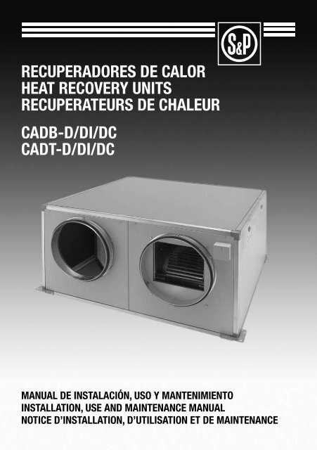
recuperadores de calor heat recovery units recuperateurs de ...
recuperadores de calor heat recovery units recuperateurs de ...
recuperadores de calor heat recovery units recuperateurs de ...
- No tags were found...

Create successful ePaper yourself
Turn your PDF publications into a flip-book with our unique Google optimized e-Paper software.
7.3.1.2. CONEXIÓN CANALIZACIÓN BATERIAS DE AGUAEn el caso <strong>de</strong> utilizar baterías <strong>de</strong> agua <strong>de</strong> post-calentamiento, se<strong>de</strong>be tener en cuenta el tipo <strong>de</strong> aparato que se ha instalado, así:Para los mo<strong>de</strong>los CADB-D, la instalación <strong>de</strong> las baterías <strong>de</strong> aguase <strong>de</strong>nomina remota, ya que la batería <strong>de</strong> agua se coloca fuera <strong>de</strong>laparato, en cualquier lugar <strong>de</strong> la canalización <strong>de</strong>seado por el usuario,en el lado <strong>de</strong> impulsión <strong>de</strong> aire al interior, tal y como se pue<strong>de</strong> ver enla siguiente imagen.El usuario o instalador, únicamente <strong>de</strong>berá instalar la batería <strong>de</strong> aguaen el punto <strong>de</strong> la canalización que le resulte más conveniente, paraa continuación, conectar los tubos <strong>de</strong> entrada y salida <strong>de</strong> la batería<strong>de</strong> agua (media pulgada para los mo<strong>de</strong>los 05, 08 y 18, y una pulgadapara los mo<strong>de</strong>los 30, 45 y 56), al circuito cerrado <strong>de</strong> agua caliente.Para los mo<strong>de</strong>los CADB-DI, se cambia la referencia por CADB-DC yla instalación <strong>de</strong> las baterías <strong>de</strong> agua se <strong>de</strong>nomina directa, ya que labatería <strong>de</strong> agua viene incorporada <strong>de</strong> fábrica en el interior <strong>de</strong>l aparato.El usuario o instalador, únicamente <strong>de</strong>berá conectar los tubos <strong>de</strong> entraday salida <strong>de</strong> la batería <strong>de</strong> agua a su circuito cerrado <strong>de</strong> agua caliente.batería aguabatería aguainstalación remotainstalación directa7.3.2. CONEXIÓN A LA RED ELÉCTRICA7.3.2.1. CONEXIÓN DE MOTORESPara los mo<strong>de</strong>los 05 y 08, bifásicos <strong>de</strong> cuatro velocida<strong>de</strong>s, se <strong>de</strong>berealizar la conexión eléctrica, según la siguiente figura:Para los mo<strong>de</strong>los 18 y 30, bifásicos <strong>de</strong> tres velocida<strong>de</strong>s, se <strong>de</strong>berealizar la conexión eléctrica, según la siguiente figura:AMARILLO / VERDEAMARILLO / VERDEMAZULBLANCOROJOGRISNEGRON1ª VEL.2ª VEL.3ª VEL.4ª VEL. MÁX.MAZULNEGRO / ROJOMARRÓNNEGRON1ª VEL.2ª VEL.3ª VEL. MÁX.Para los mo<strong>de</strong>los 45 y 56, trifásicos <strong>de</strong> una velocidad, se <strong>de</strong>be realizar la conexión eléctrica, según la siguiente figura:amarillo / ver<strong>de</strong>marrón / grisNegro / azulblanco / rojonaranjanaranjaPERSTTM400VEn los dos primeros casos, si se <strong>de</strong>sea tener el aparato conectado a una velocidad fija, solo <strong>de</strong>be elegir en cual <strong>de</strong> ellas <strong>de</strong>sea que funcioneel aparato y, conectar la toma <strong>de</strong> tierra, el neutro y la velocidad <strong>de</strong>seada, teniendo en cuenta que siempre, ambos ventiladores <strong>de</strong>benfuncionar a la misma velocidad.Si <strong>de</strong>sea tener un mayor control, y po<strong>de</strong>r controlar automáticamente la velocidad <strong>de</strong> funcionamiento <strong>de</strong>l aparato, póngase en contacto con suproveedor oficial S&P, el cual le informará sobre la amplia gama <strong>de</strong> accesorios S&P disponibles.6
7.3.2.2. CONEXIÓN RESISTENCIAS DE APOYO CADB-DIEn caso que el aparato vaya regulado por controlador: BASIC, PROGRAM, ADVANZ o DOMO, consultar las instrucciones adjuntas para realizarlas conexiones eléctricas. CADB-DI 05CADB-DI 05CADB-DI 08CADB-DI 08230V 2KWPara los mo<strong>de</strong>los 05/08/18/30 MONOFÁSICOS, se 230V <strong>de</strong>be 2KW230V 4KWrealizar la conexión eléctrica según el mo<strong>de</strong>lo y los siguientes 230V 4KWesquemas:MANUALRESETCADB-DI 05 CADB-DI 052KW230V 2KW 230V 230V 2KWMANUALRESET2KW230VMANUALRESETCADB-DI 08 CADB-DI 082KW2KW230V4KW 230V 2KW4KW230V230VMANUALRESETMANUALRESETMANUALRESET2KW230VMANUALRESETMANUALRESET2KW230V2KW230VMANUALRESETMANUALRESET2KW230VMANUALRESET2KW230VMANUALRESET2KW230V2KW230VA1 1 3 5A2 2 46230V AC A1 1 3 512A (min)cos 1A2 2 4 6230V AC12A (min)cos 1A1 1 3A2 2 4A1 1 3230V AC A1 1 3 230V AC A1 1 312A (min)230V 12A AC (min)cos 112A (min)A2 2 4cos 1A2 2 4 cos 1 A2 2 4230V AC12A (min)cos 1230V AC50Hz230V AC50HzLA1 1 3 5NL230V AC N50HzA2 2 4 6CADB-DI 30 TRIL 400V 8KWL230V ACNN50HzA1 1 3 5230V AC12A (min)cos A2 12 4 6230V AC12A (min)cos 1L230V AC N50HzL230V AC N50HzA1 1 3L230V AC N50HzA2 2 4230V AC50HzLNA1 1 3A1 1 3 A1 1 3230V AC 230V AC 230V AC12A (min) 12A (min) 12A (min)cos A2 1 2 4 cos 1A2 2 4cos A212 4230V AC12A (min)cos 1MANUALRESETMANUALRESET4KWCADB-DI 18400V230V 6KW4KWCADB-DI 400V 18230V 6KWCADB-DI 30 CADB-DI MONOCADB-DI 30 TRI 30 MONO230V 8KW 400V 8KW 230V 8KW400VAC50HzRSTN230V AC50Hz230V AC50HzLNLNMANUALRESETA1 1 3MANUALRESETA2 2 456A1 1 3A2 2 4CADB-DI 18 CADB-DI 183KW 230V 6KW 230V 6KW 3KW230V3KW 230V230VMANUALRESETMANUALRESET230V AC25A (min)cos 3KW 1230VMANUALRESETA1 1 3MANUALRESETA1 1 3 A1 1 3230V ACL230V AC 20A (min)N50Hzcos 1A2 2 4 A2 2 4CADB-DI 45 TRIL400V 12KW230V AC N50Hz3KWA2 2 4 6230VMANUALRESETA1 1 3230V ACA1 1 3230V AC20A (min)20A (min)cos 1A2 2 cos 4 14A2 25A1230V 1 AC320A (min)cos 1A2 2 4MANUALRESET230V AC25A (min)cos 3KW 1230V3KW230V3KW230V230V ACA1 1 320A (min)230V ACcos 120A (min)cos 1A2 2 4400VACA1 1 3 50Hz L230V AC 230V 230V AC ACN20A (min) 50Hz20A (min)cos A2 1 cos 12 4230V AC50HzLNMANUALRESETMANUALRESETA1 1 3A2 2 4A1 1 3L230V AC N50Hz A2 2 4230V AC50HzLNCADB-DI 30 MONO CADB-DI 30 MONO4KW 230V 8KW4KW230V 8KW 4KW230V4KW400V 230V230VMANUALRESETMANUALRESET4KW230VMANUALRESETMANUALRESETA1 1 3230V AC25A (min)cos A212 44KW230VA1 230V 1 AC325A (min)cos 1A2 2 4MANUALRESETMANUALRESET4KW230VA1 1 3 5A1 1 3 5230V ACA125A 1 (min) 3230V AC230V ACA1 A1 1 1 33cos 1 230V AC64 6A225A 2 (min) 425A A2 (min) 225A (min) cos 1cos 1A2 2cos 4 14A2 2 A2 2 4A1 1 3230V AC25A (min)cos A2 1 2 4Para los mo<strong>de</strong>los 30/45/56 TRIFASICOS, se <strong>de</strong>be realizar la conexión eléctrica según el mo<strong>de</strong>lo y los siguientes esquemas:RSTNMANUALRESETMANUALRESET4KW4KW400V230V4KW230V230V AC25A (min)230V cos AC 125A (min)cos 1230V AC25A (min)cos 1MANUALRESETMANUALRESET6KW CADB-DI 400V 30 TRI400V 8KW6KW400VCADB-DI 45 TRI400V 12KWMANUALRESETA1 1 3A2 2 4564KW400VMANUALRESET230V AC25A (min)cos 1A1 1 3A2 2 4564KW400V230V AC25A (min)cos 1MANUALRESET6KW400VMANUALRESET6KW400V400V AC50HzRSTNA1 1 3A2 2 456230V AC25A (min)cos 1A1 1 3A2 2 456230V AC25A (min)cos 1A1 1 3A2 2 456230V AC25A (min)cos 1A1 1 3A2 2 456230V AC25A (min)cos 1400VAC50HzRSTN400V AC50HzRSTNCADB-DI 56 TRI400V 12KWMANUALRESETMANUALRESETCADB-DI 6KW 45 TRI400V400V 12KW6KW400VCADB-DI 56 TRI400V 12KWMANUALRESETA1 1 3A2 2 4566KW400VMANUALRESET230V AC25A (min)cos 1A1 1 3A2 2 4566KW400V230V AC25A (min)cos 1MANUALRESET6KW400VMANUALRESET6KW400V400V AC50HzRSTNA1 1 3A2 2 456230V AC25A (min)cos 1A1 1 3A2 2 456230V AC25A (min)cos 1A1 1 3A2 2 456230V AC25A (min)cos 1A1 1 3A2 2 456230V AC25A (min)cos 1400V AC50HzRSTN7400V AC50HzRSTN
7.3.3. EVACUACIÓN DE CONDENSADOSEl instalador siempre <strong>de</strong>be conectar el tubo <strong>de</strong> <strong>de</strong>scarga <strong>de</strong> con<strong>de</strong>nsados, en el lado <strong>de</strong> expulsión <strong>de</strong>l aire interior “contaminado”, hacia elexterior. Dicha conexión <strong>de</strong>be realizarse mediante un tubo <strong>de</strong> 10 mm <strong>de</strong> diámetro interior y una brida para asegurar su fijación.Para evitar el retorno <strong>de</strong> los con<strong>de</strong>nsados por <strong>de</strong>presión al interior <strong>de</strong>l aparato, se aconseja realizar un sifón con el tubo <strong>de</strong> <strong>de</strong>scarga <strong>de</strong> con<strong>de</strong>nsados.Teniendo en cuenta que esta configuración, tiene dos posibles conexiones para el tubo <strong>de</strong> evacuación <strong>de</strong> con<strong>de</strong>nsados, seguidamente lesindicamos algunos ejemplos con aparatos <strong>de</strong> configuración horizontal.Véase que la ubicación correcta <strong>de</strong>l tubo <strong>de</strong> evacuación <strong>de</strong> con<strong>de</strong>nsados, correspon<strong>de</strong> al lado <strong>de</strong> expulsión <strong>de</strong>l aire interior “contaminado”,hacia el exterior (línea roja).Ejemplo 1Configuración horizontalLado Correcto correctoLado Correcto correctoLadoIncorreLado incorrectoIncorreincorrectoEjemplo 2Configuración verticalLado correctoLado correctoLado incorrectoLado incorrecto7.4. CONFIGURACIONES HORIZONTALES7.4.1. MODELOS CADB/CADT-D 05 / 08 / 18 / 30 / 45/ 56 CH DPMo<strong>de</strong>los sin batería eléctrica, pero con la posibilidad <strong>de</strong> instalar batería<strong>de</strong> agua, <strong>de</strong> post-calentamiento en configuración <strong>de</strong> instalaciónremota, con doble pared <strong>de</strong> aislamiento y sin by-pass.Los flujos <strong>de</strong> aire indicados en estas configuraciones, pue<strong>de</strong>n serintercambiados en función <strong>de</strong> la instalación.El instalador solo <strong>de</strong>berá tener en cuenta la correcta conexión <strong>de</strong>l sistema <strong>de</strong>evacuación <strong>de</strong>l agua generada por con<strong>de</strong>nsación (véase apartado 7.3.3).7.4.2. MODELOS CADB/CADT-D 05 / 08 / 18 / 30 / 45 /56 CH DP BPMo<strong>de</strong>los sin batería eléctrica, pero con la posibilidad <strong>de</strong> instalar batería<strong>de</strong> agua <strong>de</strong> post-calentamiento, en configuración <strong>de</strong> instalaciónremota, doble pared <strong>de</strong> aislamiento y con by-pass.Los flujos <strong>de</strong> aire indicados en estas configuraciones NO pue<strong>de</strong>n serintercambiados en función <strong>de</strong> la instalación.El instalador <strong>de</strong>berá tener en cuenta la correcta conexión <strong>de</strong>l sistema <strong>de</strong>evacuación <strong>de</strong>l agua generada por con<strong>de</strong>nsación (véase apartado 7.3.3).8
7.4.3. MODELOS CADB/CADT-DI 05 / 08 / 18 / 30 / 45 / 56 (A-D-E-G)H DP(Monofásico y trifásico)Mo<strong>de</strong>los con doble pared <strong>de</strong> aislamiento, batería eléctrica <strong>de</strong> post-calentamiento y sin by-pass.Los flujos <strong>de</strong> aire indicados en estas configuraciones, NO pue<strong>de</strong>n ser intercambiados en función <strong>de</strong> la instalación.El instalador <strong>de</strong>berá tener en cuenta la correcta conexión <strong>de</strong>l sistema <strong>de</strong> evacuación <strong>de</strong>l agua generada por con<strong>de</strong>nsación (véase apartado 7.3.3).No están autorizados posicionamientos <strong>de</strong> las resistencias <strong>de</strong> post-calentamiento, <strong>de</strong> forma diferente a los suministrados <strong>de</strong> fábrica.MODELOS CADB/CADT-DI 05 / 08 / 18 / 30 / 45 / 56 AH DPMODELOS CADB/CADT-DI 05 / 08 / 18 / 30 / 45 / 56 DH DPMODELOS CADB/CADT-DI 05 / 08 / 18 / 30 / 45 / 56 EH DPMODELOS CADB/CADT-DI 05 / 08 / 18 / 30 45 / 56 GH DP7.4.4. MODELOS CADB/CADT-DI 05 / 08 / 18 / 30 / 45 / 56 (A-D-E-G)H DP BP(Monofásico y trifásico)Mo<strong>de</strong>los con doble pared <strong>de</strong> aislamiento, batería eléctrica <strong>de</strong> post-calentamiento y con by-pass.Los flujos <strong>de</strong> aire indicados en estas configuraciones, NO pue<strong>de</strong>n ser intercambiados en función <strong>de</strong> la instalación.El instalador <strong>de</strong>berá tener en cuenta la correcta conexión <strong>de</strong>l sistema <strong>de</strong> evacuación <strong>de</strong>l agua generada por con<strong>de</strong>nsación (véase apartado 7.3.3).No están autorizados posicionamientos <strong>de</strong> las resistencias <strong>de</strong> post-calentamiento, <strong>de</strong> forma diferente a los suministrados <strong>de</strong> fábrica.MODELOS CADB/CADT-DI 05 / 08 / 18 / 30 / 45 / 56 AH DPMODELOS CADB/CADT-DI 05 / 08 / 18 / 30 / 45 / 56 DH DPMODELOS CADB/CADT-DI 05 / 08 / 18 / 30 / 45 / 56 EH DPMODELOS CADB/CADT-DI 05 / 08 / 18 / 30 / 45 / 56 GH DP9
7.4.5. MODELOS CADB/CADT-DC 05 / 08 / 18 / 30 / 45 / 56 (A-D-E-G)H DP(Monofásico y trifásico)Mo<strong>de</strong>los con doble pared <strong>de</strong> aislamiento, batería <strong>de</strong> agua <strong>de</strong> post-calentamiento y sin by-pass.Los flujos <strong>de</strong> aire indicados en estas configuraciones, NO pue<strong>de</strong>n ser intercambiados en función <strong>de</strong> la instalación.El instalador <strong>de</strong>berá tener en cuenta la correcta conexión <strong>de</strong>l sistema <strong>de</strong> evacuación <strong>de</strong>l agua generada por con<strong>de</strong>nsación (véase apartado 7.3.3).No están autorizados posicionamientos <strong>de</strong> las baterías <strong>de</strong> agua <strong>de</strong> post-calentamiento, <strong>de</strong> forma diferente a los suministrados <strong>de</strong> fábrica.MODELOS CADB/CADT-DC 05 / 08 / 18 / 30 / 45 / 56 AH DPMODELOS CADB/CADT-DC 05 / 08 / 18 / 30 / 45 / 56 DH DPMODELOS CADB/CADT-DC 05 / 08 / 18 / 30 / 45 / 56 EH DPMODELOS CADB/CADT-DC 05 / 08 / 18 / 30 45 / 56 GH DP7.4.6. MODELOS CADB/CADT-DC 05 / 08 / 18 / 30 / 45 / 56(A-E-D-G)H DP BP(Monofásico y trifásico)Mo<strong>de</strong>los con doble pared <strong>de</strong> aislamiento, batería <strong>de</strong> agua <strong>de</strong> post-calentamiento y con by-pass.Los flujos <strong>de</strong> aire indicados en estas configuraciones, NO pue<strong>de</strong>n ser intercambiados en función <strong>de</strong> la instalación.El instalador <strong>de</strong>berá tener en cuenta la correcta conexión <strong>de</strong>l sistema <strong>de</strong> evacuación <strong>de</strong>l agua generada por con<strong>de</strong>nsación (véase apartado 7.3.3).No están autorizados posicionamientos <strong>de</strong> las baterías <strong>de</strong> agua <strong>de</strong> post-calentamiento, <strong>de</strong> forma diferente a los suministrados <strong>de</strong> fábrica.MODELOS CADB/CADT-DC 05 / 08 / 18 / 30 / 45 / 56 AH DP BP MODELOS CADB/CADT-DC 05 / 08 / 18 / 30 / 45 / 56 DH DP BPMODELOS CADB/CADT-DC 05 / 08 / 18 / 30 / 45 / 56 EH DP BPMODELOS CADB/CADT-DC 05 / 08 / 18 / 30 45 / 56 GH DP BP10
7.5. CONFIGURACIONES VERTICALES7.5.1. MODELOS CADB/CADT-D 05 / 08 / 18 / 30 / 45 /56 (A-B-H)V DPMo<strong>de</strong>los sin batería eléctrica, pero con la posibilidad <strong>de</strong> instalar batería<strong>de</strong> agua, <strong>de</strong> post-calentamiento en configuración <strong>de</strong> instalación remota,con doble pared <strong>de</strong> aislamiento y sin by-pass.Los flujos <strong>de</strong> aire indicados en estas configuraciones, pue<strong>de</strong>n ser intercambiadosen función <strong>de</strong> la instalación.El instalador solo <strong>de</strong>berá tener en cuenta la correcta conexión <strong>de</strong>l sistema <strong>de</strong>evacuación <strong>de</strong>l agua generada por con<strong>de</strong>nsación (véase apartado 7.3.3).A partir <strong>de</strong> la configuración <strong>de</strong> fábrica, po<strong>de</strong>mos configurar el aparato,teniendo en cuenta que po<strong>de</strong>mos girar el mismo modificando la posición<strong>de</strong> los pies <strong>de</strong> soporte, y a su vez, también tendremos que modificar laposición <strong>de</strong> la ban<strong>de</strong>ja “recoge agua” según la configuración elegida.7.5.2. MODELOS CADB/CADT-D 05 / 08 / 18 / 30 / 45 / 56(A-D-H)V DP BPMo<strong>de</strong>los sin batería eléctrica, pero con la posibilidad <strong>de</strong> instalar batería<strong>de</strong> agua <strong>de</strong> post-calentamiento en configuración <strong>de</strong> instalaciónremota, doble pared <strong>de</strong> aislamiento y con by-pass.Los flujos <strong>de</strong> aire indicados en estas configuraciones, NO pue<strong>de</strong>n serintercambiados en función <strong>de</strong> la instalación.7.5.3. MODELOS CADB/CADT-DI 05 / 08 / 18 / 30 / 45 / 56 (C-D-E)V DP(Monofásico y trifásico)Mo<strong>de</strong>los con doble pared <strong>de</strong> aislamiento, batería <strong>de</strong> agua <strong>de</strong> post-calentamiento y sin by-pass.Los flujos <strong>de</strong> aire indicados en estas configuraciones, NO pue<strong>de</strong>n ser intercambiados en función <strong>de</strong> la instalación.El instalador <strong>de</strong>berá tener en cuenta la correcta conexión <strong>de</strong>l sistema <strong>de</strong> evacuación <strong>de</strong>l agua generada por con<strong>de</strong>nsación (véase apartado 7.3.3).No están autorizados posicionamientos <strong>de</strong> las baterías <strong>de</strong> agua <strong>de</strong> post-calentamiento, <strong>de</strong> forma diferente a los suministrados <strong>de</strong> fábrica.MODELOS CADB/CADT-DI 05 / 08 / 18 / 30 / 45 / 56 CV DPMODELOS CADB/CADT-DI 05 / 08 / 18 / 30 / 45 / 56 DV DPMODELOS CADB/CADT-DI 05 / 08 / 18 / 30 / 45 / 56 EV DP7.5.4. MODELOS CADB/CADT-DI 05 / 08 / 18 / 30 / 45 / 56 (C-D-E)V DP BP(Monofásico y trifásico)Mo<strong>de</strong>los con doble pared <strong>de</strong> aislamiento, batería <strong>de</strong> agua <strong>de</strong> post-calentamiento y con by-pass.Los flujos <strong>de</strong> aire indicados en estas configuraciones, NO pue<strong>de</strong>n ser intercambiados en función <strong>de</strong> la instalación.El instalador <strong>de</strong>berá tener en cuenta la correcta conexión <strong>de</strong>l sistema <strong>de</strong> evacuación <strong>de</strong>l agua generada por con<strong>de</strong>nsación (véase apartado 7.3.3).No están autorizados posicionamientos <strong>de</strong> las baterías <strong>de</strong> agua <strong>de</strong> post-calentamiento, <strong>de</strong> forma diferente a los suministrados <strong>de</strong> fábrica.11
MODELOS CADB/CADT-DI 05 / 08 / 18 / 30 / 45 / 56 CV DP BPMODELOS CADB/CADT-DI 05 / 08 / 18 / 30 / 45 / 56 DV DP BPMODELOS CADB/CADT-DI 05 / 08 / 18 / 30 / 45 / 56 EV DP BP7.5.5. MODELOS CADB/CADT-DC 05 / 08 / 18 / 30 / 45 / 56 (C-D-E)V DP(Monofásico y trifásico)Mo<strong>de</strong>los con doble pared <strong>de</strong> aislamiento, batería <strong>de</strong> agua <strong>de</strong> post-calentamiento y sin by-pass.Los flujos <strong>de</strong> aire indicados en estas configuraciones, NO pue<strong>de</strong>n ser intercambiados en función <strong>de</strong> la instalación.El instalador <strong>de</strong>berá tener en cuenta la correcta conexión <strong>de</strong>l sistema <strong>de</strong> evacuación <strong>de</strong>l agua generada por con<strong>de</strong>nsación (véase apartado 7.3.3).No están autorizados posicionamientos <strong>de</strong> las baterías <strong>de</strong> agua <strong>de</strong> post-calentamiento, <strong>de</strong> forma diferente a los suministrados <strong>de</strong> fábrica.MODELOS CADB/CADT-DC 05 / 08 / 18 / 30 / 45 / 56 CV DPMODELOS CADB/CADT-DC 05 / 08 / 18 / 30 / 45 / 56 DV DPMODELOS CADB/CADT-DC 05 / 08 / 18 / 30 / 45 / 56 EV DP7.5.6. MODELOS CADB/CADT-DC 05 / 08 / 18 / 30 / 45 / 56 (C-D-E)V DP BP(Monofásico y trifásico)Mo<strong>de</strong>los con doble pared <strong>de</strong> aislamiento, batería <strong>de</strong> agua <strong>de</strong> post-calentamiento y con by-pass.Los flujos <strong>de</strong> aire indicados en estas configuraciones, NO pue<strong>de</strong>n ser intercambiados en función <strong>de</strong> la instalación.El instalador <strong>de</strong>berá tener en cuenta la correcta conexión <strong>de</strong>l sistema <strong>de</strong> evacuación <strong>de</strong>l agua generada por con<strong>de</strong>nsación (véase apartado 7.3.3).No están autorizados posicionamientos <strong>de</strong> las baterías <strong>de</strong> agua <strong>de</strong> post-calentamiento, <strong>de</strong> forma diferente a los suministrados <strong>de</strong> fábrica.12
MODELOS CADB/CADT-DC 05 / 08 / 18 / 30 / 45 / 56 CV DP BPMODELOS CADB/CADT-DC 05 / 08 / 18 / 30 / 45 / 56 DV DP BPMODELOS CADB/CADT-DC 05 / 08 / 18 / 30 / 45 / 56 EV DP BP8. CONEXIÓN DEL MOTOR DEL BY – PASSPara la instalación véase lo anteriormente <strong>de</strong>scrito, <strong>de</strong>pendiendo <strong>de</strong>ltipo <strong>de</strong> instalación (configuración horizontal o vertical) y conecte elservomotor <strong>de</strong>l by-pass (montado en fábrica) tal y como se indicaen la siguiente figura:9. PUESTA EN MARCHAREDAC 230 VAntes <strong>de</strong> la puesta en marcha, es conveniente realizar las siguientes verificaciones:- Asegúrese <strong>de</strong> que en el interior <strong>de</strong>l aparato no haya cuerpos extraños y que todos los componentes estén fijos en su lugar.- Compruebe manualmente que el ventilador no roza en las pare<strong>de</strong>s.- Verifique que la trampilla <strong>de</strong> inspección este cerrada.ATENCIÓN:Si las bocas <strong>de</strong> un ventilador no están canalizadas se <strong>de</strong>be instalar una red <strong>de</strong> protección a<strong>de</strong>cuada.Verifique la conexión eléctrica <strong>de</strong> toma <strong>de</strong> tierra.La conexión eléctrica <strong>de</strong>be ser realizada por personal cualificado.AZUL (4)NEGRO (6)BLANCO (7)10. INSPECCIÓN, MANTENIMIENTO Y LIMPIEZA10.1. FILTROSEl control <strong>de</strong>l estado <strong>de</strong> obstrucción <strong>de</strong> los filtros, pue<strong>de</strong> efectuarse a través <strong>de</strong> las tomas <strong>de</strong> presión especiales situadas a ambos lados <strong>de</strong> losfiltros, en el costado inferior <strong>de</strong> la unidad, en el caso <strong>de</strong> la configuración horizontal, y en uno <strong>de</strong> los lados, en caso <strong>de</strong> configuración vertical,conectándolo a un presostato diferencial.La caída <strong>de</strong> presión máxima recomendada en los filtros estándar G4 es <strong>de</strong> 130/150 Pa.- Inspección por el lado <strong>de</strong> la unidad:Utilizando un <strong>de</strong>stornillador <strong>de</strong> corte, hacer rotar el cierre <strong>de</strong>l “Panel <strong>de</strong> inspección <strong>de</strong> filtro” hacia la izquierda y quitar el panel.Hacer presión en el filtro hacia la <strong>de</strong>recha en los clips <strong>de</strong> sujeción y extraer el filtro.- Inspección <strong>de</strong>l bajo:Soltar los pestillos <strong>de</strong> cierre <strong>de</strong>l “Panel <strong>de</strong> inspección <strong>de</strong> filtros” y sacar el panel, agarrar la manilla <strong>de</strong>l filtro y <strong>de</strong>sbloquear los clips que losostienen, estirando a continuación hacia abajo.- Mantenimiento periódico aconsejado:En función <strong>de</strong> la contaminación <strong>de</strong>l aire ambiente (polvo, humo…), se recomienda sustituir el filtro entre 15 y 30 días como máximo.13
10.2. INTERCAMBIADOR DE CALORUtilizando un <strong>de</strong>stornillador <strong>de</strong> corte, extraer los cuatro tornillos <strong>de</strong> los pestillos <strong>de</strong>l panel <strong>de</strong> inspección <strong>de</strong>l intercambiador.Rotar los cuatro pestillos <strong>de</strong> anclaje hasta liberar la tapa <strong>de</strong>l panel para su posterior extracción.Utilizando un <strong>de</strong>stornillador <strong>de</strong> estrella, soltar los tornillos <strong>de</strong> fijación <strong>de</strong> la barra <strong>de</strong> seguridad situada en el ángulo <strong>de</strong>l intercambiador.Girar la barra <strong>de</strong> seguridad hasta liberar el intercambiador.10.3. TUBO DE DESAGÜE DE CONDENSADOS11. ANOMALÍAS DE FUNCIONAMIENTOANOMALÍA CAUSA SOLUCIÓNArranque difícil.Caudal <strong>de</strong> aire insuficiente.Presión insuficiente.Caída <strong>de</strong> rendimiento<strong>de</strong>spués <strong>de</strong> un periodo <strong>de</strong>funcionamiento aceptable.Temperatura aire nuevo<strong>de</strong>masiado fría.Rendimiento insuficiente <strong>de</strong>lintercambiador.Formación <strong>de</strong> escarcha enel intercambiador.Pulsación <strong>de</strong> aire.¡¡¡ATENCIÓN!!! Sostener con una mano el intercambiador durante esta operación para evitar su caídapor gravedad (riesgo <strong>de</strong> daños en el intercambiador y riesgo <strong>de</strong> acci<strong>de</strong>nte para el técnico que realiza laoperación).Para extraer el intercambiador <strong>de</strong> su ubicación, <strong>de</strong>slícelo por sus guías, tirando <strong>de</strong> los ángulos y no <strong>de</strong> lasaletas <strong>de</strong>l intercambiador, para no dañarlo.Limpie el intercambiador con aire comprimido o con un aspirador y lávelo con <strong>de</strong>tergente no agresivo.El mantenimiento periódico recomendado es <strong>de</strong> una vez por cada estación en funcionamiento.Inspeccione periódicamente el tubo <strong>de</strong> <strong>de</strong>sagüe <strong>de</strong> con<strong>de</strong>nsados, para evitar que que<strong>de</strong> atascado y, en ese caso, retire los restos que loatasquen.Tensión <strong>de</strong> alimentación reducida.Par estático <strong>de</strong>l motor insuficiente.Tuberías atascadas y/o puntos <strong>de</strong>aspiración cerrados.Ventilador obstruido.Filtro sobrecargado.Velocidad <strong>de</strong> rotación insuficiente.Paquete intercambiador obturado.Fuga en el circuito antes y/o <strong>de</strong>spués<strong>de</strong>l ventilador.Ro<strong>de</strong>te dañado.Aire exterior inferior a -5º C.Mo<strong>de</strong>los (CADB-DI): Protectores térmicos.Resistencias <strong>de</strong> Apoyo abiertos.Aletas intercambio sucias.Aire exterior inferior a -5º C.Ventilador que trabaja en condiciones<strong>de</strong> caudal casi igual a 0.Inestabilidad <strong>de</strong> flujo, obstrucción omala conexión.Verificar datos <strong>de</strong> placa <strong>de</strong>l motor.Cerrar las entradas <strong>de</strong> aire para alcanzar la máxima velocidad.Si es necesario, cambie el motor.Contacte con el Servicio Post Venda <strong>de</strong> S&P.Limpieza <strong>de</strong> los tubos <strong>de</strong> aspiración.Limpieza <strong>de</strong>l ventilador.Limpiar o sustituir el filtro.Verificar la tensión <strong>de</strong> alimentación.Limpieza <strong>de</strong>l intercambiador.Verificación <strong>de</strong>l circuito y restauración <strong>de</strong> las condiciones originales.Verificar el ro<strong>de</strong>te y en caso necesario, sustituirlo con un recambiooriginal. Contacte con el Servicio Post Venda <strong>de</strong> S&P.Inserción dispositivos <strong>de</strong> postcalentamiento.Contacte con el Servicio Post Venda <strong>de</strong> S&P.Rearme mediante el pulsador RESET, todos los protectores térmicos <strong>de</strong>la resistencia.Limpieza <strong>de</strong>l intercambiador.Inserción <strong>de</strong> dispositivos <strong>de</strong> precalentamiento (anti-hielo).Contacte con el Servicio <strong>de</strong> Asesorías <strong>de</strong> S&P.Modificación <strong>de</strong>l circuito y/o sustitución <strong>de</strong>l ventilador.Limpieza y/o reajuste canales <strong>de</strong> aspiración. Intervenir en el reguladorelectrónico aumentando la velocidad mínima (voltaje insuficiente).Contacte con el Servicio <strong>de</strong> Asesorías <strong>de</strong> S&P.14
ENGLISHINDEX1. Introduction 162. Safety regulations and “ce” marking 163. General instructions 164. Unit labelling 165. Handling 166. Instruction symbols 167. Installation 177.1. Introduction 177.2. Maintenance space 177.3. Connections 177.3.1. Piping and duct connections 177.3.1.1. Connection with air duct 177.3.1.2. Connecting the water battery piping 187.3.2. Connecting to the mains 187.3.2.1. Connecting the motors 187.3.2.2. Connecting support resistances cadb-dI 197.3.3. Evacuation of con<strong>de</strong>nsate 207.4. Horizontal configurations 207.4.1. CADB/CADT-D 05 / 08 / 18 / 30 / 45 / 56 CH DP mo<strong>de</strong>ls 207.4.2. CADB/CADT-D 05 / 08 / 18 / 30 / 45 / 56 CH DP BP mo<strong>de</strong>ls 207.4.3. CADB/CADT-DI 05 / 08 / 18 / 30 / 45 / 56 (A-D-E-G)H DP mo<strong>de</strong>ls 217.4.4. CADB/CADT-DI 05 / 08 / 18 / 30 / 45 / 56 (A-D-E-G)H DP BP mo<strong>de</strong>ls 217.4.5. CADB/CADT-DC 05 / 08 / 18 / 30 / 45 / 56 (A-D-E-G)H DP mo<strong>de</strong>ls 227.4.6. CADB/CADT-DC 05 / 08 / 18 / 30 / 45 / 56(A-E-D-G)H DP BP mo<strong>de</strong>ls 227.5. Vertical configurations 237.5.1. CADB/CADT-D 05 / 08 / 18 / 30 / 45 / 56 (A-B-H)V DP mo<strong>de</strong>ls 237.5.2. CADB/CADT-D 05 / 08 / 18 / 30 / 45 / 56 (A-D-H)V DP BP mo<strong>de</strong>ls 237.5.3. CADB/CADT-DI 05 / 08 / 18 / 30 / 45 / 56 (C-D-E)V DP mo<strong>de</strong>ls 237.5.4. CADB/CADT-DI 05 / 08 / 18 / 30 / 45 / 56 (C-D-E)V DP BP mo<strong>de</strong>ls 237.5.5. CADB/CADT-DC 05 / 08 / 18 / 30 / 45 / 56 (C-D-E)V DP mo<strong>de</strong>ls 247.5.6. CADB/CADT-DC 05 / 08 / 18 / 30 / 45 / 56 (C-D-E)V DP BP mo<strong>de</strong>ls 248. Connecting the by – pass motor 259. Start up 2510. Inspection, maintenance and cleaning 2510.1. Filters 2510.2 Heat exchanger 2610.3. Drainpipe for con<strong>de</strong>nsate 2611. Operation anomalies 2615
1. INTRODUCTIONThank you for purchasing this appliance. It has been manufactured in full compliance with applicable safety regulations and EU standards.Please read this instruction book carefully, as it contains important information for your safety during the installation, use and maintenanceof this product.Keep it at hand for future reference.Please check that the appliance is in perfect condition when you unpack it, as all factory <strong>de</strong>fects are covered by the S&P guarantee.2. SAFETY REGULATIONS AND “CE” MARKINGS&P technicians are firmly committed to research and <strong>de</strong>velopment of ever more efficient products and in compliance with current safetyregulations.The instructions and recommendations given below reflect current regulations, principally regarding safety, and therefore are based oncompliance with general regulations. Therefore, we recommend all people exposed to hazards to strictly follow the safety regulations in forcein your country. S&P will not be held liable for any possible harm or damage caused by non-compliance with the safety regulations, as wellas caused by modifying the product.The CE mark and the corresponding <strong>de</strong>claration of conformity are proof of the product’s conformity with current EU regulations.3. GENERAL INSTRUCTIONSA hazard analysis of the product has been carried out as provi<strong>de</strong>d in the Machine Directive. This manual contains information for all personnelexposed to these hazards, with the aim of preventing possible harm or damage due to faulty handling or maintenance.All maintenance operations (ordinary and extraordinary) must be carried out with the machine switched off and the electrical power supplydisconnected.To avoid a possible acci<strong>de</strong>ntal start up, place a warning notice on the electrical control panel with the following text:“Attention: control disconnected for maintenance operations”Before connecting the power supply cable to the terminal strip, make sure the mains voltage corresponds to the voltage indicated on thespecifications plate of the unit.Regularly check the product labels. If, due to the passing of time, they are no longer legible, they must be replaced.4. UNIT LABELLINGThe machine may come with several pictogrammes that must not be removed. These signs are divi<strong>de</strong>d into:- Prohibition signs: Do not repair or adjust when in operation.- Danger signs: Warning of the presence of live elements insi<strong>de</strong> the container bearing the sign.- I<strong>de</strong>ntification signs: CE card, indicating product information and manufacturer’s address. The CE mark indicates the product’s conformitywith EEC standards.Danger signsProhibition sign5. HANDLINGBefore installing, make sure that the <strong>de</strong>vice to be used for moving and/or raising the product has sufficient capacity.6. INSTRUCTION SYMBOLSWATERCOILCentrifugalfanFILTERexhaust airELECTRICHEATERDoublethicknessisolationdrainfresh air16
7. INSTALLATION7.1. INTRODUCTIONHorizontally configured mo<strong>de</strong>ls are <strong>de</strong>signed to be installed hanging from the ceiling or located insi<strong>de</strong> a false ceiling.The appliance has four metal abutments, one on each lower corner. Using stud<strong>de</strong>d rods (Ø 6 mm or Ø 8 mm), it can be secured to the ceilingand levelled.The installer must make sure that the ceiling structure and thesecuring elements can bear the weight of the <strong>de</strong>vice, taking intoaccount that it is a dynamic load.Vertical configuration mo<strong>de</strong>ls have special support feet.Once the <strong>de</strong>vice has been fitted in the correct position, the installermust connect it with the air duct, the mains connection, both for themotors, and for the batteries, if applicable, by means of the terminalsin the terminal connection box and the connection with the hot waterclosed circuit for the water battery, if applicable. The tube for evacuatingcon<strong>de</strong>nsates will be secured according to the instructions in thecorresponding section.7.2. MAINTENANCE SPACEHorizontalMo<strong>de</strong>lA(mm)B(mm)C(mm)D(mm)C AB D B D BD B B DVerticalCADB-D/DI/DC 05 345 400 400 640CADB-D/DI/DC 08 360 400 400 820CADB-D/DI/DC 18 535 400 600 1040CADB-D/DI/DC 30 630 500 700 1270CADT-D/DI/DC 45 855 500 900 1300BCADT-D/DI/DC 56 855 500 900 1300CC100100B BA AMo<strong>de</strong>lA(mm)B(mm)C(mm)CADB-D/DI/DC 05 400 640 740CADB-D/DI/DC 08 400 820 920CADB-D/DI/DC 18 600 1040 1140CADB-D/DI/DC 30 700 1270 1370CADT-D/DI/DC 45 900 1300 1300CADT-D/DI/DC 56 900 1300 13007.3. CONNECTIONS7.3.1. PIPING AND DUCT CONNECTIONS7.3.1.1. CONNECTION WITH AIR DUCTThe standard configuration displays the route of fresh air blown into the premises in blue, while used air and its route until it is expelled from thepremised is in red.The fans are always blowing out with regard to the machine.The fans must not be positioned in a manner different to the one indicated.17
7.3.1.2. CONNECTING THE WATER BATTERY PIPINGIf post-<strong>heat</strong>ing water batteries are used, take into account the typeof <strong>de</strong>vice installed, thus:For mo<strong>de</strong>ls CADB-D, the installation of water batteries is remote, asthe water battery is outsi<strong>de</strong> the <strong>de</strong>vice, placed in any part of the ductthe user wishes, on the si<strong>de</strong> of blowing the air insi<strong>de</strong>, as can be seenin the following illustration.The user or installer must only install the water coil in the most convenientpoint, then connect the water coil inlet and outlet pipes (Halfan inch for mo<strong>de</strong>ls 05, 08 and 18, and one inch for mo<strong>de</strong>ls 30, 45 and56), to the hot water circuit.For CADB-DI mo<strong>de</strong>ls, the reference is changed to CADB-DC and theinstallation of the water batteries is called direct, as the water coil isbuilt into the appliance.The user or installer only needs to collect the water coil inlet andoutlet tubes to its hot water closed circuit.Water coilWater coilRemote InstallationDirect installation7.3.2. CONNECTING TO THE MAINS7.3.2.1. CONNECTING THE MOTORSFor two-phase, four-speed mo<strong>de</strong>ls 05 and 08, the electrical connectionwill be ma<strong>de</strong> as <strong>de</strong>scribed in the following illustration:For two-phase, three-speed mo<strong>de</strong>ls 18 and 30, electrical connectionwill be ma<strong>de</strong> as <strong>de</strong>scribed in the following illustration:YELLOW / GREENYELLOW / GREENMBLUEWHITEREDGREYBLACKN1ª SPEED2ª SPEED3ª SPEED4ª MAX. SPEEDMBLUEBLACK / REDBROWNBLACKN1ª SPEED2ª SPEED3ª MAX SPEEDFor two-phase, one-speed mo<strong>de</strong>ls 45 and 56, electrical connection will be ma<strong>de</strong> as <strong>de</strong>scribed in the following illustration:Yellow / GreenBROWN / GreyBLACK / BLUEwhite / REDorangeorangePERSTTM400VIn the first two cases, if you wish to have the appliance connected at a fixed speed, just choose which you need and connect the earth, theneutral and the <strong>de</strong>sired speed, always taking into account that both fans must work at the same speed.If you wish to have greater control, and to be able to control the speed of operation of the <strong>de</strong>vice, please contact your official S&P <strong>de</strong>aler, whowill inform you of the wi<strong>de</strong> range of S&P accessories that are available.18
7.3.2.2. CONNECTING SUPPORT RESISTANCES CADB-DIIf the mo<strong>de</strong>l is regulated by a control: BASIC, PROGRAM, ADVANZ or DOMO, see the attached instructions for making electrical connections.For SINGLE-PHASE mo<strong>de</strong>ls 05/08/18/30, CADB-DI electrical 05CADB-DI connection 05 will be ma<strong>de</strong> as <strong>de</strong>scribed in the CADB-DI following 08 illustration: CADB-DI 08230V 2KW230V 2KW230V 4KW230V 4KWMANUALRESETCADB-DI 05 CADB-DI 052KW230V 2KW 230V 230V 2KWMANUALRESET2KW230VMANUALRESETCADB-DI 08 CADB-DI 082KW2KW230V4KW 230V 2KW4KW230V230VMANUALRESETMANUALRESETMANUALRESET2KW230VMANUALRESETMANUALRESET2KW230V2KW230VMANUALRESETMANUALRESET2KW230VMANUALRESET2KW230VMANUALRESET2KW230V2KW230VA1 1 3 5A2 2 46230V AC A1 1 3 512A (min)cos 1A2 2 4 6230V AC12A (min)cos 1A1 1 3A2 2 4A1 1 3230V AC A1 1 3 230V AC A1 1 312A (min)230V 12A AC (min)cos 112A (min)A2 2 4cos 1A2 2 4 cos 1 A2 2 4230V AC12A (min)cos 1230V AC50Hz230V AC50HzLA1 1 3 5NL230V AC N50HzA2 2 4 6CADB-DI 30 TRIL 400V 8KWL230V ACNN50HzA1 1 3 5230V AC12A (min)cos A2 12 4 6230V AC12A (min)cos 1L230V AC N50HzL230V AC N50HzA1 1 3L230V AC N50HzA2 2 4230V AC50HzLNA1 1 3A1 1 3 A1 1 3230V AC 230V AC 230V AC12A (min) 12A (min) 12A (min)cos A2 1 2 4 cos 1A2 2 4cos A212 4230V AC12A (min)cos 1MANUALRESETMANUALRESET4KWCADB-DI 18400V230V 6KW4KWCADB-DI 400V 18230V 6KWCADB-DI 30 CADB-DI MONOCADB-DI 30 TRI 30 MONO230V 8KW 400V 8KW 230V 8KW400VAC50HzRSTN230V AC50HzMANUALRESETcos 3KW 1230VMANUALRESETCADB-DI 45 TRIFor THREE-PHASE mo<strong>de</strong>ls 30/45/56, L400V 12KW electrical connection will be ma<strong>de</strong> as <strong>de</strong>scribed LLin the following illustration:230V AC50HzLNLNMANUALRESETA1 1 3A2 2 4A1 1 3A2 2 4A1 1 3L230V AC N50HzA2 2 4230V AC50Hz56NCADB-DI 18 CADB-DI 183KW 230V 6KW 230V 6KW 3KW230V3KW 230V230VMANUALRESETMANUALRESET230V AC25A (min)MANUALRESETA1 1 3A1 1 3230V ACA1 1 3230V AC20A (min)20A (min)cos 1A2 2 cos 4 14A2 2A1 1 3230V AC20A (min)cos A2 1 2 453KWA2 2 4 6230VMANUALRESETA1230V 1 AC320A (min)cos 1A2 2 4MANUALRESET230V AC25A (min)cos 3KW 1230V3KW230V3KW230V230V ACA1 1 320A (min)230V ACcos 120A (min)cos 1A2 2 4400VACA1 1 3 50Hz L230V AC 230V 230V AC ACN20A (min) 50Hz20A (min)cos A2 1 cos 12 4230V AC50HzNMANUALRESETMANUALRESETRSTNA1 1 3A2 2 4A1 1 3L230V AC N50Hz A2 2 4230V AC50HzMANUALRESETNCADB-DI 30 MONO CADB-DI 30 MONO4KW 230V 8KW4KW230V 8KW 4KW230V4KW400V 230V230VMANUALRESETMANUALRESET4KW230VMANUALRESETMANUALRESETA1 1 3230V AC25A (min)cos A212 44KW230VMANUALRESETA1 230V 1 AC325A (min)cos 1A2 2 4MANUALRESETMANUALRESET4KW230VA1 1 3 5A1 1 3 5230V ACA125A 1 (min) 3230V AC230V ACA1 A1 1 1 33cos 1 230V AC64 6A225A 2 (min) 425A A2 (min) 225A (min) cos 1cos 1A2 2cos 4 14A2 2 A2 2 4A1 1 3230V AC25A (min)cos A2 1 2 44KW4KW400V230V4KW230V230V AC25A (min)230V cos AC 125A (min)cos 1230V AC25A (min)cos 1MANUALRESETMANUALRESET6KW CADB-DI 400V 30 TRI400V 8KW6KW400VCADB-DI 45 TRI400V 12KWMANUALRESETA1 1 3A2 2 4564KW400VMANUALRESET230V AC25A (min)cos 1A1 1 3A2 2 4564KW400V230V AC25A (min)cos 1MANUALRESET6KW400VMANUALRESET6KW400V400V AC50HzRSTNA1 1 3A2 2 456230V AC25A (min)cos 1A1 1 3A2 2 456230V AC25A (min)cos 1A1 1 3A2 2 456230V AC25A (min)cos 1A1 1 3A2 2 456230V AC25A (min)cos 1400VAC50HzRSTN400V AC50HzRSTNCADB-DI 56 TRI400V 12KWMANUALRESETMANUALRESETCADB-DI 6KW 45 TRI400V400V 12KW6KW400VCADB-DI 56 TRI400V 12KWMANUALRESETA1 1 3A2 2 4566KW400VMANUALRESET230V AC25A (min)cos 1A1 1 3A2 2 4566KW400V230V AC25A (min)cos 1MANUALRESET6KW400VMANUALRESET6KW400V400V AC50HzRSTNA1 1 3A2 2 456230V AC25A (min)cos 1A1 1 3A2 2 456230V AC25A (min)cos 1A1 1 3A2 2 456230V AC25A (min)cos 1A1 1 3A2 2 456230V AC25A (min)cos 1400V AC50HzRSTN19400V AC50HzRSTN
7.3.3. EVACUATION OF CONDENSATEThe installer must always connect the con<strong>de</strong>nsate evacuation tube on the outlets si<strong>de</strong> of the interior “used” air, to the outsi<strong>de</strong>. This connectionmust be ma<strong>de</strong> with a 10 mm internal diameter tube and a tie to secure it.To avoid the con<strong>de</strong>nsates returning to the appliance, we recommend fitting a siphon to the con<strong>de</strong>nsate evacuation tube.Bearing in mind that this configuration has two possible connections for the con<strong>de</strong>nsate evacuation tube, we will show some examples withhorizontally configured appliances.Observe that the correct location of the con<strong>de</strong>nsate evacuation tube is on the si<strong>de</strong> where the “used” interior air is expelled (red line).Example 1Horizontal configurationCorrect Lado Correcto si<strong>de</strong>Correct Lado Correcto si<strong>de</strong>Incorrect Lado si<strong>de</strong>Incorrect Lado si<strong>de</strong>Example 2Vertical configurationCorrect Lado correcto si<strong>de</strong>Correct Lado correcto si<strong>de</strong>Incorrect Lado incorrecto si<strong>de</strong>Incorrect Lado incorrecto si<strong>de</strong>7.4. HORIZONTAL CONFIGURATIONS7.4.1. CADB/CADT-D 05 / 08 / 18 / 30 / 45 / 56 CH DPmo<strong>de</strong>lsMo<strong>de</strong>ls without an electric battery, but with the possibility of installinga water coil, for post-<strong>heat</strong>ing in remote installation configuration,with a double insulation wall and no by-pass.The airflows indicted in these configurations can be changed, accordingto the installation.The installer must only take into account the correct connection of the evacuationsystem for water produced by con<strong>de</strong>nsation (See section 7.3.3).7.4.2. CADB/CADT-D 05 / 08 / 18 / 30 / 45 / 56 CH DP BPMODELSMo<strong>de</strong>ls without an electric battery, but with the possibility of installinga water coil, for post-<strong>heat</strong>ing in remote installation configuration,with a double insulation wall and with a by-pass.The airflows indicted in these configurations CANNOT be changed,according to the installation.The installer must take into account the correct connection of the evacuationsystem for water produced by con<strong>de</strong>nsation (See section 7.3.3).20
7.4.3. CADB/CADT-DI 05 / 08 / 18 / 30 / 45 / 56 (A-D-E-G)H DP MODELS(Single-phase and three-phase)Mo<strong>de</strong>ls with double insulating wall, post <strong>heat</strong>ing electric battery and no by-pass.The airflows indicted in these configurations CANNOT be changed, according to the installation.The installer must take into account the correct connection of the evacuation system for water produced by con<strong>de</strong>nsation (See section 7.3.3).Do not position the post-<strong>heat</strong>ing resistances in a different manner to the factory-supplied layout.CADB/CADT-DI 05 / 08 / 18 / 30 / 45 / 56 AH DP MODELSCADB/CADT-DI 05 / 08 / 18 / 30 / 45 / 56 DH DP MODELSCADB/CADT-DI 05 / 08 / 18 / 30 / 45 / 56 EH DP MODELSCADB/CADT-DI 05 / 08 / 18 / 30 45 / 56 GH DP MODELS7.4.4. CADB/CADT-DI 05 / 08 / 18 / 30 / 45 / 56 (A-D-E-G)H DP BP MODELS(Single and three phase)Mo<strong>de</strong>ls with double insulating wall, post <strong>heat</strong>ing electric battery and with a by-pass.The airflows indicted in these configurations CANNOT be changed, according to the installation.The installer must take into account the correct connection of the evacuation system for water produced by con<strong>de</strong>nsation (See section 7.3.3).Do not position the post-<strong>heat</strong>ing resistances in a different manner to the factory-supplied layout.CADB/CADT-DI 05 / 08 / 18 / 30 / 45 / 56 AH DP MODELSCADB/CADT-DI 05 / 08 / 18 / 30 / 45 / 56 DH DP MODELSCADB/CADT-DI 05 / 08 / 18 / 30 / 45 / 56 EH DP MODELSCADB/CADT-DI 05 / 08 / 18 / 30 / 45 / 56 GH DP MODELS21
7.4.5. CADB/CADT-DC 05 / 08 / 18 / 30 / 45 / 56 (A-D-E-G)H DP MODELS(Single and three phase)Mo<strong>de</strong>ls with double insulating wall, post <strong>heat</strong>ing water coil and no by-pass.The airflows indicted in these configurations CANNOT be changed, according to the installation.The installer must take into account the correct connection of the evacuation system for water produced by con<strong>de</strong>nsation (See section 7.3.3).Do not position the post-<strong>heat</strong>ing water coil in a different manner to the factory-supplied layout.CADB/CADT-DC 05 / 08 / 18 / 30 / 45 / 56 AH DP MODELSCADB/CADT-DC 05 / 08 / 18 / 30 / 45 / 56 DH DP MODELSCADB/CADT-DC 05 / 08 / 18 / 30 / 45 / 56 EH DP MODELSCADB/CADT-DC 05 / 08 / 18 / 30 45 / 56 GH DP MODELS7.4.6. CADB/CADT-DC 05 / 08 / 18 / 30 / 45 / 56(A-E-D-G)H DP BP MODELS(Single and three phase)Mo<strong>de</strong>ls with double insulating wall, post <strong>heat</strong>ing water coil and with a by-pass.The airflows indicted in these configurations CANNOT be changed, according to the installation.The installer must take into account the correct connection of the evacuation system for water produced by con<strong>de</strong>nsation (See section 7.3.3).Do not position the post-<strong>heat</strong>ing water coil in a different manner to the factory-supplied layout.CADB/CADT-DC 05 / 08 / 18 / 30 / 45 / 56 AH DP BP MODELSCADB/CADT-DC 05 / 08 / 18 / 30 / 45 / 56 DH DP BP MODELSCADB/CADT-DC 05 / 08 / 18 / 30 / 45 / 56 EH DP BP MODELSCADB/CADT-DC 05 / 08 / 18 / 30 45 / 56 GH DP BP MODELS22
7.5. Vertical configurationS7.5.1. CADB/CADT-D 05 / 08 / 18 / 30 / 45 / 56 (A-B-H)V DP MODELSMo<strong>de</strong>ls without an electric battery, but with the possibility of installinga water coil, for post-<strong>heat</strong>ing in remote installation configuration,with a double insulation wall and no by-pass.The airflows indicted in these configurations can be changed, accordingto the installation.The installer must only take into account the correct connection of the evacuationsystem for water produced by con<strong>de</strong>nsation (See section 7.3.3).From the factory configuration, we can configure the appliance, takinginto account that we can turn it , thus modifying the position ofthe support feet, and at the same time, it will also be necessary tomodify the position of the “water collection” tray, according to thechosen configuration.7.5.2. CADB/CADT-D 05 / 08 / 18 / 30 / 45 / 56 (A-D-H)VDP BP MODELSMo<strong>de</strong>ls without an electric battery, but with the possibility of installinga water coil, for post-<strong>heat</strong>ing in remote installation configuration,with a double insulation wall and with a by-pass.The airflows indicted in these configurations CANNOT be changed,according to the installation.7.5.3. CADB/CADT-DI 05 / 08 / 18 / 30 / 45 / 56 (C-D-E)V DP MODELS(Single and three phase)Mo<strong>de</strong>ls with double insulating wall, post <strong>heat</strong>ing water coil and no by-pass.The airflows indicted in these configurations CANNOT be changed, according to the installation.The installer must take into account the correct connection of the evacuation system for water produced by con<strong>de</strong>nsation (See section 7.3.3).Do not position the post-<strong>heat</strong>ing resistances in a different manner to the factory-supplied layout.CADB/CADT-DI 05 / 08 / 18 / 30 / 45 / 56 CV DP MODELSCADB/CADT-DI 05 / 08 / 18 / 30 / 45 / 56 DV DP MODELSCADB/CADT-DI 05 / 08 / 18 / 30 / 45 / 56 EV DP MODELS7.5.4. CADB/CADT-DI 05 / 08 / 18 / 30 / 45 / 56 (C-D-E)V DP BP MODELS(Single and three phase)Mo<strong>de</strong>ls with double insulating wall, post <strong>heat</strong>ing electric battery and with a by-pass.The airflows indicted in these configurations CANNOT be changed, according to the installation.The installer must take into account the correct connection of the evacuation system for water produced by con<strong>de</strong>nsation (See section 7.3.3).Do not position the post-<strong>heat</strong>ing resistances in a different manner to the factory-supplied layout.23
CADB/CADT-DI 05 / 08 / 18 / 30 / 45 / 56 CV DP BP MODELSCADB/CADT-DI 05 / 08 / 18 / 30 / 45 / 56 DV DP BP MODELSCADB/CADT-DI 05 / 08 / 18 / 30 / 45 / 56 EV DP BP MODELS7.5.5. CADB/CADT-DC 05 / 08 / 18 / 30 / 45 / 56 (C-D-E)V DP MODELS(Single and three phase)Mo<strong>de</strong>ls with double insulating wall, post <strong>heat</strong>ing electric battery and no by-pass.The airflows indicted in these configurations CANNOT be changed, according to the installation.The installer must take into account the correct connection of the evacuation system for water produced by con<strong>de</strong>nsation (See section 7.3.3).Do not position the post-<strong>heat</strong>ing resistances in a different manner to the factory-supplied layout.CADB/CADT-DC 05 / 08 / 18 / 30 / 45 / 56 CV DP MODELSCADB/CADT-DC 05 / 08 / 18 / 30 / 45 / 56 DV DP MODELSCADB/CADT-DC 05 / 08 / 18 / 30 / 45 / 56 EV DP MODELS7.5.6. CADB/CADT-DC 05 / 08 / 18 / 30 / 45 / 56 (C-D-E)V DP BP MODELS(Single and three phase)Mo<strong>de</strong>ls with double insulating wall, post <strong>heat</strong>ing water coil and with a by-pass.The airflows indicted in these configurations CANNOT be changed, according to the installation.The installer must take into account the correct connection of the evacuation system for water produced by con<strong>de</strong>nsation (See section 7.3.3).Do not position the post-<strong>heat</strong>ing water coil in a different manner to the factory-supplied layout.24
MODELS CADB/CADT-DC 05 / 08 / 18 / 30 / 45 / 56 CV DP BPCADB/CADT-DC 05 / 08 / 18 / 30 / 45 / 56 DV DP BP MODELSCADB/CADT-DC 05 / 08 / 18 / 30 / 45 / 56 EV DP BP MODELS8. CONNECTING THE BY– PASS MOTORFor installation, see the <strong>de</strong>scription above, <strong>de</strong>pending on the type of installation(Horizontal or vertical configuration) and connect the servomotor ofthe by-pass (factory-fitted) as indicated in the following illustration:9. START UPREDAC 230 VBefore starting, it is recommendable to carry out the following verifications:- Make sure there are no foreign bodies insi<strong>de</strong> the <strong>de</strong>vice and that all components are secured on their positions.- Ensure manually that the fan does not touch the walls.- Make sure that the inspection hatch is closed.ATTENTION:If the outlets of the fan are not ducted an a<strong>de</strong>quate protection net must be fitted.Check the earth connection.The electrical connection should be ma<strong>de</strong> by qualified personnel.BLUE (4)Black (6)White (7)10. INSPECTION, MAINTENANCE AND CLEANING10.1. FILTERSThe state of the filters can be checked by means of special pressure take off points located on both si<strong>de</strong>s of the filters, on the lower si<strong>de</strong> ofthe unit, in the case of horizontal configuration, and on one of the si<strong>de</strong>s in the case of vertical configuration, connecting it to a differentialpressure switch.The maximum recommen<strong>de</strong>d fall in pressure in the standard G4 filters is 130/150 Pa.- Inspection through the si<strong>de</strong> of the unit:Using the cutting screwdriver, rotate the catch of the “Filter inspection panel” to the left and remove the panel.Press the filter to the right in the securing clips and remove the filter.- Inspection of the bottom:Release the closing bolts of the “Filter inspection panel” and remove the panel, grasp the filter handle and unlock the clips that secure itand then pull it downwards.- Recommen<strong>de</strong>d regular maintenance:Depending on the air pollution (Dust, smoke…), it is recommen<strong>de</strong>d to replace the filter every 15 to 30 days at the most.25
10.2 HEAT EXCHANGERUsing a screwdriver, remove the four screws of the <strong>heat</strong> exchanger inspection panel bolts.Rotate the four securing bolts until the panel is free and can be removed.Using a star screwdriver, release the bolts securing the safety bar located in the angle of the <strong>heat</strong> exchanger.ATTENTION! Hold the exchanger with one hand during this operation to avoid it falling (risk of damagingthe exchanger and risk of acci<strong>de</strong>nt for the technician carrying out the operation).To remove the exchanger from its location, sli<strong>de</strong> it along its gui<strong>de</strong>s, pulling by the handle and not theexchanger fins, so as not to damage the exchanger.Clean the exchanger with compressed air or with a vacuum cleaner and wash it with a mild <strong>de</strong>tergent.The recommen<strong>de</strong>d regular maintenance should be carried out once per season when it is in operation.10.3. DRAINPIPE FOR CONDENSATERegularly inspect the drainpipe for con<strong>de</strong>nsates to make sure it is not blocked, if this is the case, remove the obstruction.11. OPERATION ANOMALIESDifficult to start.ANOMALY CAUSE SOLUTIONInsufficient airflow.Insufficient pressure.Reduction in performanceafter a period of acceptableoperation.New air temperature toocold.Insufficient performance ofthe exchanger.Formation of frost on theexchanger.Reduced power supply voltage.Insufficient static torque of motor.Blocked pipes and/or inlet points closed.Fan obstructed.Filter overloa<strong>de</strong>d.Insufficient rotation speed.Exchanger package blocked.Leaks in the circuit before and/or afterthe fan.Damaged roller.Outsi<strong>de</strong> air -5º C or less.Mo<strong>de</strong>ls (CADB-DI): Thermal protectorsSupport resistances open.Fins dirty.Outsi<strong>de</strong> air below -5º C.Air pulsation. Fan working in flow conditions almost 0.Flow instability, obstruction or badconnection.Check motor specification plate.Close the air inlets to reach the maximum speed.Change the motor is necessary.Contact the S&P Post-Sales service.Clean inlet tubes.Clean fan.Clean or replace filter.Check power supply voltage.Clean the exchanger.Check the circuit and restore original conditions.Check the impeller and if necessary, replace with an original spare part.Contact the S&P post sales service.Insertion of post-<strong>heat</strong>ing resistances.Contact the S&P post sales service.Reset by pushing the button RESET, all the thermal protectors of theresistance.Clean the exchanger.Insertion of post-<strong>heat</strong>ing <strong>de</strong>vices (anti-ice).Contact the S&P Customer Advice service.Modification of the circuit and/or replacement of the fan.Clean and/or readjust the inlet channels. Operate the electronic regulator,increasing the minimum speed (insufficient voltage).Contact the S&P Customer Advice service.26