Edelstahl Verbindungstechnik Stainless steel jointing technology ...
Edelstahl Verbindungstechnik Stainless steel jointing technology ...
Edelstahl Verbindungstechnik Stainless steel jointing technology ...
- No tags were found...

You also want an ePaper? Increase the reach of your titles
YUMPU automatically turns print PDFs into web optimized ePapers that Google loves.
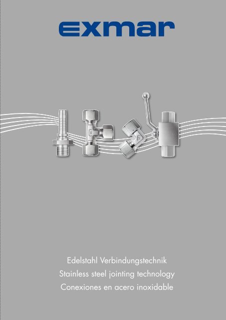
Sicher verbunden mit…Reliable connection with…conexión segura con…Vertrauen Sie auf die exzellenteQualität unserer Rohr- undSchlauchverbindungen.Wir verwenden ausschließlich hochwertigen<strong>Edelstahl</strong> für die Herstellung unsererBauteile und arbeiten kontinuierlich an derNeu- und Weiterentwicklung unserer Produkte.Um Ihnen stets die passende Lösung zubieten, haben wir für Sie das Sortimentder Schlaucharmaturen und Schläuche erweitertund optimiert. Profitieren Sie vonunserer technischen Kompetenz. EXMARSchlaucharmaturen sind zuverlässig, auchim Einsatz mit ungeschälten Schläuchenund hohen Drücken.Trust in the excellent quality ofour tube and hose connections.We use only high-quality stainless <strong>steel</strong> tomanufacture our components and are continuouslyadding new developments to ourproduct range.In order to offer you a more fitting solution,we have expanded and optimised ourrange of hose fittings and hoses. You benefitfrom our technical expertise. EXMARhose fittings are reliable, even with unpeeledhoses and high pressures.Confíe en la extraordinariacalidad de nuestras uniones paratubos rígidos y flexibles.Utilizamos exclusivamente acero inoxidablede alta calidad para la fabricación denuestros componentes y trabajamos continuamenteen la creación de productosnuevos y el desarrollo de los existentes.Hemos ampliado y optimizado la gamade tuberías flexibles y los racores correspondientespara poder ofrecer en todomomento la solución más adecuada. Benefíciesede nuestra capacidad técnica. Losracores para tubos flexibles EXMAR sonfiables aunque se utilicen con altas presionesen mangueras sin pelar.Weitere Informationen finden Sie in denKapiteln Schlaucharmaturen (Kapitel 60)sowie Rohre und Schläuche (Kapitel 70).For more information, please see Hose Fittings(Chapter 60) and Tubes and Hoses(Chapter 70).Encontrará más información en los capítulossobre racores para tubos flexibles (capítulo60) y tubos rígidos y flexibles (capítulo 70).
Inhaltsverzeichnis Index IndiceInhaltContentsContenidoiDienstleistungenReinigungenGewindeabdichtungenSonderkonstruktionenServicesCleaningThread sealsSpecial designsServiciosLimpiezasSellado de roscasModelos especialessSchneidringverschraubungenCutting Ring FittingsRacores de anillo cortante10Bördel-RohrverschraubungenFlared Tube FittingsRacores rebordeados20DichtkegelverschraubungenTapered Seal ConnectionsRacores cónicos con juntatórica30Kugelhähne, VentileNiederdruck-KugelhähneHochdruck-KugelhähneRückschlagsventileVentileBall and Needle ValvesLow pressure ball valveHigh pressure ball valveNon-return valveValveLlave esférica, VálvulaLlave esférica de baja presiónLlave esférica de alta presiónVálvula de retenciónVálvula40NC-KlemmringverschraubungenNC Clamping Ring FittingsRacores de anillo deapriete NC50SchlaucharmaturenHose CouplingsArmaduras para tubos60Rohre und SchläucheTubes and HosesTubos y Mangueras70Zubehör und WerkzeugAccessories and ToolsAccesorios y Utillajes80AnhangMontageanleitungenTechnsiche ErläuterungenBeständigkeitslisteAppendixAssembly instructionsTechnical instructionsTable of chemical resistanceAnexoInstrucciones de montajeInstrucciones técnicaLista de constancia químicaa
sDienstleistungenReinigungenGewindeabdichtungenSonderkonstruktionenServicesCleaningThread sealsSpecial designsServiciosLimpiezasSellado de roscasModelos especiales
Dienstleistungen Service ServicioÜbersicht Overview Vista generals.3Spezialbehandlung für Einsatzmit SauerstoffSpecial treatmentfor use with oxygenTratamiento especial paraaplicaciones con oxígenos.4Spezialbehandlung –silikonfreiSpecial treatment –silicone freeTratamiento especial –libre de siliconas.5Spezialreinigung –entfettetSpecial treatment –degreasedLimpieza especial –desengrasados.6VorbeschichteteEinschraubgewinde mitLoctite 5061Pre-coated threadswith Loctite 5061Roscas de conexión recubiertas,con Loctite 5061s.7VorbeschichteteEinschraubgewinde mitPTFE-Band umwickeltPre-coated threadswith PTFE-tapeRoscas de conexión recubiertas,envueltas con cinta de PTFEs.8Trockenschmierung für<strong>Edelstahl</strong>verschraubungenDry lubrification forstainless <strong>steel</strong> unionsLubricación seca para racoresde acero inoxidables.9 Engineering Engineering Ingenierías.10 Sonderanfertigungen Special designed products Modelos especialess.11 Baugruppen Pre assembled kits Gruposs.12Konfektionierte LeitungenRohre biegenReady-to-fitBended tubesTuberías confeccionadasDoblado de tuboss.1
Dienstleistungen Service ServicioVerträglichkeitsmatrixCompatibility matrixMatriz de compatibilidadesis10 erhältlichavailabledisponible nicht möglichnot availableno disponible20304050607080as.2
Dienstleistungen Service ServicioSpezialbehandlung für Einsatz mit Sauerstoff (Öl- und fettfrei)Special treatment for use with oxygen (oil and grease-free)Tratamiento especial para aplicaciones con oxígeno(libres de aceite y grasas)AnwendungsgebietRohrverbinder und Armaturen, diein Sauerstoffsystemen zum Einsatzgelangen,unterliegen hohen Sauberkeitsanforderungen.Speziell, was dieMenge der Kohlenstoffverbindungenauf der Oberfläche (Öle u. Fette)betrifft. Derartige Verunreinigungenkönnen sich sehr einfach und schnellselbst entzünden.QualitätOberflächensauberkeit< 33mg/m2 TOC gem. ASTM*G93-96, Stufe B.Jeder Auftrag ist rückverfolgbar,Montage und Prüfung in speziellsauberer UmgebungEXMAR-Spezifikation CSO-OX*American Society for Testing and materialsLieferumfang– Komponenten einzelverpackt– verschweisst in PE-Beuteln– Spezial Etikett– einbaufertig vormontiert– initial geschmiertSchmierstoffSpezialschmierstoff AC 851OX, mitZulassung vom BAM*(Details s. Kapitel Zubehör)* Bundesanstalt für Materialforschung und-prüfungBestellhinweisEXMAR-Produkte, die nach CSO-OX gereinigt und geliefert werdensollen, müssen bei der Bestellungklar mit der Erweiterung OX nachder Materialnummer oder derTypenbezeichnung gekennzeichnetsein.Application areaTube connectors and valves whichare used in oxygen systems havevery high cleanliness requirements,especially in regard tocarbon compounds on the surface(oils and greases). Such contaminationcould self-ignite very easily andvery quickly.QualitySurface cleanliness< 33mg/m2 TOC per ASTM* G93-96, Level B.Every order is traceable; assemblyand testing are done in a special,clean environment.EXMAR specifications CSO-OX*American Society for Testing and materialsScope of supplyComponents are packagedindividually in weld-sealed PE bags,clearly marked, pre-assembled forinstallation, initial lubrication.LubricantSpecial lubricant AC 851 OX,approved by BAM*(Details see chapter accessories)* Bundesanstalt für Materialforschung und-prüfungOrdering informationEXMAR products which need to becleaned and supplied according toCSO-OX must be clearly markedwith OX after the material number orthe type description when ordering.Campo de aplicaciónLos empalmes de tubos y las valvuleríasque se utilizan en sistemasde conducción de oxígeno debencumplir rigurosos requisitos de limpieza,especialmente en lo que serefiere a la cantidad de compuestoscarbonados adheridos a la superficie(aceites y grasas). Este tipo decontaminación es sumamente autoinflamable.CalidadLimpieza de la superficie< 33mg/m2 TOC según ASTM*G93-96, nivel B.Se pueden rastrear todos lospedidos, montaje y ensayo en entornosespecialmente limpios, especificaciónEXMAR CSO-OX.*American Society for Testing and materials(Sociedad Americana de Ensayos y Materiales)Contenido del paquete– componentes embalados porseparado– soldados en bolsas de PE– etiqueta especial– montados listos para instalar– con lubricación de fábricaLubricanteLubricante especial AC 851OX conhomologación del BAM*(para detalles, consultar el capítulode accesorios)* Bundesanstalt für Materialforschung und -prüfung(Instituto Alemán de Investigación y Ensayo de Materiales)Instrucciones de pedidoLos productos EXMAR que debanlimpiarse y suministrarse conformea la especificación CSO-OX han deidentificarse inequívocamente con elsuplemento OX después del númerode material o de la denominación detipo en el pedido.Beispiel:oderWEV-22LR 3.4 OX708.2406.768.21 OXe.g.:orWEV-22LR 3.4 OX708.2406.768.21 OXEjemplo:oWEV-22LR 3.4 OX708.2406.768.21 OXs.3
Dienstleistungen Service ServicioSpezialbehandlung – silikonfreiSpecial treatment – silicone-freeTratamiento especial – libre de siliconaiAnwendungsgebietRohrverbinder und Armaturen, dievornehmlich mit Farben und Lackenin Kontakt kommen, dürfen auf dermedienberührten Oberfläche keineSilikonverbindungen aufweisen, dadiese die Benetzung der Oberflächeverhindern.QualitätOberflächensauberkeit< 33mg/m2 TOC gem. ASTM*G93-96, Stufe B.Jeder Auftrag ist rückverfolgbar,Montage und Prüfung in speziellsauberer Umgebung, EXMAR-Spezifikation CSO-OX.Application areaTube connectors and valves whichprimarily come into contact withpaints and varnishes may not haveany silicon compounds on themedia-contacting surfaces becausethese would prevent wetting of thesurfaces.QualitySurface cleanliness< 33mg/m2 TOC per ASTM*G93-96, level B.Every order is traceable; assemblyand testing are done in a special,clean environment, EXMAR specificationsCSO-OX.Campo de aplicaciónLos empalmes de tubos y las valvuleríasque entren en contacto especialmentecon pinturas y barnicesdeben tener superficies libres decompuestos de silicona, pues estasimpiden que la superficie se moje.CalidadLimpieza de la superficie< 33mg/m2 TOC según ASTM*G93-96, nivel B.Se pueden rastrear todos lospedidos, montaje y ensayo en entornosespecialmente limpios, especificaciónEXMAR CSO-OX.s1020*American Society for Testing and materialsDer gesamte Fertigungsprozess istsilikonfrei.*American Society for Testing and materialsThe whole production process issilicone-free.*American Society for Testing and materials(Sociedad Americana de Ensayos y Materiales)Todo el proceso de fabricación estálibre de siliconas.30Lieferumfang– Komponenten einzelverpackt– verschweisst in PE-Beuteln– Spezial Etikett– einbaufertig vormontiert– initial geschmiertScope of supplyParts are individually packaged, inweld-sealed PE bags, special label,pre-assembled for installation, initiallubrication.Contenido del paquete– componentes embalados porseparado– soldados en bolsas de PE– etiqueta especial– montados listos para instalar– con lubricación de fábrica40SchmierstoffWo notwendig, wird ein garantiertsilikonfreier Schmierstoff verwendet.LubricantWhere necessary, a guaranteed silicone-freelubricant is used.LubricanteSe utilizará un lubricante garantizadolibre de siliconas cuando seanecesario.50BestellhinweisEXMAR-Komponenten, die nachCSO-OX gereinigt und silikonfreigeliefert werden sollen,müssen bei der Bestellung klarmit der Erweiterung SI nachder Materialnummer oder derTypenbezeichnung gekennzeichnetsein.Beispiel:oderWEV-22LR 3.4 SI708.2406.768.21 SIOrdering informationEXMAR components which need tobe cleaned and supplied siliconefreeaccording to CSO-OX mustbe clearly marked with SI after thematerial number or the type descriptionwhen ordering.e.g.:orWEV-22LR 3.4 SI708.2406.768.21 SIInstrucciones de pedidoLos componentes EXMAR que debanlimpiarse y suministrarse libres desilicona conforme a la especificaciónCSO-OX han de identificarseinequívocamente con el suplementoSI después del número de materialo de la denominación de tipo en elpedido.Ejemplo:oWEV-22LR 3.4 SI708.2406.768.21 SI607080as.4
Dienstleistungen Service ServicioSpezialreinigung – entfettet – ungeschmiertSpecial cleaning – degreased – unlubricatedLimpieza especial – desengrasado – sin lubricaciónAnwendungsgebietÜberall, wo eine spezielleOberflächensauberkeit der medienberührtenTeile benötigt wird,der Kunde aber sein eigenesSchmiermittel verwenden möchte.Application areaWherever special surface cleanlinessis required for parts that come intocontact with the media, but wherethe customer wishes to use his ownlubricant.Campo de aplicaciónEn aplicaciones que requieren unalimpieza especial de las superficiesde las piezas en contacto con elmedio y el cliente quiera utilizar supropio lubricante.QualitätOberflächensauberkeit< 33mg/m2 TOC gem. ASTM*G93-96, Stufe B.Jeder Auftrag ist rückverfolgbar,Montage und Prüfung in speziellsauberer Umgebung, EXMAR-Spezifikation CSO-OXQualitySurface cleanliness< 33mg/m2 TOC per ASTM*G93-96, Level B.Every order is traceable; assemblyand testing are done in a special,clean environment, EXMAR specificationsCSO-OXCalidadLimpieza de la superficie < 33mg/m2 TOC según ASTM* G93-96,nivel B.Todos los pedidos son rastreables,montaje y ensayo en entornos especialmentelimpios, especificaciónEXMAR CSO-OX.*American Society for Testing and materials*American Society for Testing and materials*American Society for Testing and materials(Sociedad Americana de Ensayos y Materiales)Lieferumfang– einzelverpackt– verschweisst in PE-Beuteln– Spezial-Etikett– unmontiert d.h. lose Mutterund KlemmringWichtiger HinweisDie Teile sind grösstenteils ungeschmiert, einzelne Stellen müssenaus funktionstechnischen Gründengeschmiert werden.Vor der Montage müssen Mutterund Klemmring unbedingt mit einemgeeigneten Schmiermittel geschmiertwerden.Scope of supplyIndividually packaged in weldsealedPE bags, special label, notassembled, i.e. loose nut and compressionferruleImportant informationThe parts are generally not lubricated,however certain points must belubricated for optimal functioning.Prior to assembly, the nut and thecompression ferrule must be lubricatedwith a suitable lubricant.Contenido del paquete– embalaje por separado– soldados en bolsas de PE– etiqueta especial– sin montar, es decir, tuerca y anillode apriete sueltosImportanteAunque las piezas no llevan generalmentelubricación, hay determinadospuntos que deben lubricarse porcuestiones técnicas relacionadas conel funcionamiento.Lubricar siempre la tuerca y el anillode apriete con un lubricante adecuadoantes del montaje.vor Installation schmierenlubricate before installationantes de la Installación hay que engrasarbereits mit AC 851-OX geschmiertalready lubricated with AC 851-OXya está engrasado con AC 851-OXBestellhinweisEXMAR-Produkte, die entfettet undungeschmiert geliefert werdensollen, müssen bei der Bestellungklar mit der Erweiterung US nachder Materialnummer oder derTypenbezeichnung gekennzeichnetsein.Ordering informationEXMAR products which need to besupplied degreased and unlubricatedmust be clearly marked with USafter the material number or the typedescription when ordering.Instrucciones de pedidoLos productos EXMAR que debansuministrarse desengrasados y sinlubricación han de identificarseinequívocamente con el suplementoUS después del número de materialo de la denominación de tipo en elpedido.Beispiel:oderWEV-22LR 3.4 US708.2406.768.21 USe.g:orWEV-22LR 3.4 US708.2406.768.21 USEjemplo:oWEV-22LR 3.4 US708.2406.768.21 USs.5
Dienstleistungen Service ServicioVorbeschichtete Gewinde mit Loctite 5061Pre-coated threads with Loctite 5061Roscas recubiertas con Loctite 5061iDurch vorbeschichteteGewinde erreichen Sie eineoptimale Abdichtung vonkonischen Aussengewinden.With pre-coated threads youobtain optimal sealing oftapered outside threads.Las roscas recubiertas permitenconseguir un selladoóptimo de roscas exteriorescónicas.sDas wasserbasierte, nichthärtendeund nichttoxische GewindedichtmittelLoctite 5061 wird maschinell aufgetragen.Auf diese Weise ist sichergestellt,dass die Dichtmasse gleichmässigund direkt bei den potentiellenLeckagestellen im Gewindegrundund auf den Gewindeflanken aufgebrachtwird. Dadurch wird optimalfür höchste Dichtheit und Sicherheitgesorgt. Vorbeschichtete Gewindevon EXMAR sind vielseitig einsetzbar.The water-based, non-hardening,non-toxic sealing compound Loctite5061 is applied by machine. Thisassures that the sealing compound isapplied evenly and directly at potentialleakage points at the base andthe flank of the thread, thus providingextreme leak-tightness and reliability.Pre-coated threads from EXMARmay be used in a wide variety ofapplications.El sellador de roscas Loctite 5061,de base acuosa no endurecible, notóxico, se aplica mediante procedimientosmecánicos. De este modose asegura la aplicación uniformey directa de la masa selladora enlos posibles puntos de pérdida delfondo y de los flancos de la roscapara obtener una estanquidad yseguridad óptimas. Las roscas recubiertasde EXMAR tienen numerosasaplicaciones.1020• Dichtmittel Loctite5061 Dri-Seal• Montagefertig• Umweltfreundlich• Ungiftig, lösungsmittelfrei• Sehr gute Medienbeständigkeit• Zulassung von:DVGW, KTW, SVGWTechnische Daten*• Chemische Basis:Polyacrylat wässrig,nicht härtend• Temperatur:-50°C bis +150°C• Druck (PN):16 bar, andere Drücke möglich• Justierbarkeit:45° (DIN 30660)• Einsatzmedien:Luft, Öl, Wasser (heiss, kalt)Hinweis: Loctite 5061 ist nicht geeignet fürden Einsatz mit reinem Sauerstoff.• Loctite 5061 Dri-SealSealing Compound• Ready for assembly• Environmentally friendly• Non-toxic, solvent-free• Very good media resistance• Approved by:DVGW, KTW, SVGWTechnical Data*• Chemical base:Polyacrylate, aqueous,non-hardening• Temperature:-50°C to +150°C• Pressure (PN)16 bar, others possible• Adjustability:45° (DIN 30660)• Media:air, oil, water (hot, cold)Note: Loctite 5061 is unsuitable for usewith pure oxygen.• Sellador Loctite 5061 Dri-Seal• Listo para el montaje• Respetuoso con el medio ambiente• No tóxico, no contiene disolventes• Muy buena resistencia a líquidosy gases• Homologaciones:DVGW, KTW, SVGWDatos técnicos*• Base química:poliacrilato acuoso, no endurecible• Temperatura:-50°C a +150°C• Presión (PN):16 bar, otras presiones posibles• Margen de ajuste:45° (DIN 30660)• Medios en los que se aplica:aire, aceite, agua (caliente, fría)Advertencia: Loctite 5061 no sirve parasellar oxígeno puro.30405060*Die Angaben stammen vom Hersteller vonLoctite 5061. Änderungen sind vorbehalten.Die Klärung der Einsatztauglichkeit vonbeschichteten Gewinden der EXMAR liegtin der Verantwortung des Konstrukteurs undmuss vorgängig geprüft werden. EXMARlehnt jegliche Haftung ab.*The data comes from the manufacturer ofLoctite 5061. These are subject to changewithout notice. Clarification of the suitabilityfor use of coated threads from EXMAR is theresponsibility of the designer and must becarried out in advance. EXMAR will acceptno liability there after.*Información proporcionada por elfabricante de Loctite 5061. Reservadoel derecho ha realizar modificaciones. Elfabricante que las utilice es el responsablede verificar de antemano la idoneidad delas roscas recubiertas de EXMAR para cadaaplicación. EXMAR declina toda responsabilidad.70BestellhinweisEXMAR-Produkte, die mit beschichtetenGewinden geliefert werdensollen, müssen bei der Bestellungklar mit der Erweiterung CT nachder Materialnummer oder derTypenbezeichnung gekennzeichnetsein.Beispiel:oderWEV-22LR 3.4 CT708.2406.768.21 CTOrdering informationEXMAR products which need to besupplied with coated threads mustbe clearly marked with CT after thematerial number or the type descriptionwhen ordering.e.g:orWEV-22LR 3.4 CT708.2406.768.21 CTInstrucciones de pedidoLos productos EXMAR que debansuministrarse con roscas recubiertashan de identificarse inequívocamentecon el suplemento CT despuésdel número de material o de la denominaciónde tipo en el pedido.Ejemplo:oWEV-22LR 3.4 CT708.2406.768.21 CT80as.6
Dienstleistungen Service ServicioVorbeschichtete Einschraubgewinde mit PTFE-Band umwickeltPre-coated threads with PTFE-tapeRoscas de conexión recubiertas, envueltas con cinta de PTFEAnwendungsgebietDie Alternative zur Option CT, diePTFE-Band-Umwicklung, eignet sichspeziell– bei Temperaturen über +150°– bei agressiven Medien– bei Dampf– für reinen SauerstoffQualitätDie Gewinde sind aus Gründen derbesseren Haftung teilweise aufgeraut.Das 0.08 mm dicke PTFE-Bandwird mind. 2x umwickelt wobei dererste Gewindegang frei bleibt.LieferumfangIn Standardverpackungen, einbaufertigvormontiert, initial geschmiertBestellhinweisEXMAR-Produkte, die mit umwickeltenGewinden geliefert werdensollen, müssen bei der Bestellungklar mit der Erweiterung CP nachder Materialnummer oder derTypenbezeichnung gekennzeichnetsein.Application areaAs an alternative to the CT option,PTFE tape is especially suitable– for temperatures above +150°– for aggressive media– for steam– for pure oxygenQualityThe threads are roughened for betteradhesion. The 0.08 mm thick PTFEtape is wrapped at least 2x, whilekeeping the first screw thread free.Scope of supplyIn standard packages, ready forinstallation, pre-assembled, initiallubricationOrdering informationEXMAR products which need to besupplied with wrapped threads mustbe clearly marked with CP after thematerial number or the type descriptionwhen ordering.Campo de aplicaciónLa alternativa a la opción CT, elrecubrimiento con cinta de PTFE, esespecialmente adecuada para:– temperaturas de más de +150°– medios agresivos– vapor– oxígeno puroCalidadLas roscas se han raspado en partepara mejorar la adherencia. Lacinta PTFE de 0.08 mm de grosorse enrolla por lo menos 2 capas,dejando descubierta la primeravuelta de la rosca.Contenido del paqueteEn embalajes estándar, premontadaslistas para instalar, con lubricaciónde fábricaInstrucciones de pedidoLos productos EXMAR que debansuministrarse con roscas envueltashan de identificarse inequívocamentecon el suplemento CP después delnúmero de material o de la denominaciónde tipo en el pedido.Beispiel:oderWEV-22LR 3.4 CP708.2406.768.21 CPe.g.:orWEV-22LR 3.4 CP708.2406.768.21 CPEjemplo:oWEV-22LR 3.4 CP708.2406.768.21 CPs.7
Dienstleistungen Service ServicioTrockenschmierung für <strong>Edelstahl</strong>verschraubungenDry lubrication for stainless <strong>steel</strong> unionsLubricación seca para racores de acero inoxidableiMit dieser einzigartigenBeschichtung reduzierenSie das Anzugsmomentdeutlich.Reduce torque significantlywith this unique coating.Este recubrimiento originalpermite reducir claramenteel par de apriete.sDie Option Trockenschmierungeignet sich bei Einsatz mit höchstenAnsprüchen, insbesondere fürVerbindungen die oft wiederholtmontiert und demontiert werdenmüssen, denn ein Nachschmierenentfällt, was die Sicherheit massiverhöht.QualitätDie Anzugskräfte verringern sich beider Erstmontage um bis zu 50 %,der Montagestopp ist einfachererkennbar.Technische Daten• Betriebsdruck:gemäss Katalogangaben• Temperaturbereich:-40°C bis +220°CBestellhinweisEXMAR-Produkte, die mitTrockenschmierung geliefert werdensollen, müssen bei der Bestellungklar mit der Erweiterung DL nachder Materialnummer oder derTypenbezeichnung gekennzeichnetsein.The dry lubrication option is idealfor highly demanding applications,especially for unions that need tobe repeatedly disassembled andreassembled since re-lubrication isnot required. This greatly improvessafety.QualityThe tightening forces are reduced forthe first installation by up to 50 %.The installation stop is clearly visible.Technical data• Operating pressure:according to catalogue specifications• Temperature range:-40°C to +220°COrdering informationEXMAR products which are to besupplied with dry lubrication must beclearly identifiable in the order withthe extension DL after the materialnumber or the material description.La opción de lubricación seca esidónea para aplicaciones muyexigentes, especialmente para conexionesque se montan y desmontanfrecuentemente, porque no es necesariovolver a lubricar y las cotas deseguridad aumentan claramente.CalidadLas fuerzas de apriete se reducenhasta un 50% en el montaje inicialy es más fácil detectar el tope demontaje.Datos técnicos• Presión de servicio:según datos del catálogo• Intervalo de temperatura:-40°C a +220°CInstrucciones de pedidoLos productos EXMAR que debansuministrarse con lubricación secahan de identificarse inequívocamentecon el suplemento DL después delnúmero de material o de la denominaciónde tipo en el pedido.1020304050Beispiel:oderWEV-22LR 3.4 DL708.2406.768.21 DLe.g.:orWEV-22LR 3.4 DL708.2406.768.21 DLEjemplo:oWEV-22LR 3.4 DL708.2406.768.21 DL607080as.8
Dienstleistungen Service ServicioEngineeringEngineeringIngenieríaPassgenaue Lösungen fürSie – entwickelt von EXMAREngineeringBeratungWir beraten Sie kompetent undmit großer Erfahrung in derProduktentwicklung. Sie bekommenvon uns Lösungsvorschläge, die inder harten Realität bestehen können.Ihr Vorteil - unsere Erfahrung!EXMAR Engineering developstailor-made solutions– also for youConsultingOur many years experience inproduct development enables usto advise you in a knowledgeable,competent manner and to proposeappropriate application solutions.– Our experience is your advantage!Soluciones a su medidadesarrolladas por EXMAREngineeringAsesoramientoAsesoramiento competente y ampliaexperiencia en el desarrollo deproductos. Le propondremos solucionesque superarán con creces lasduras condiciones del día a día. Suventaja: nuestra experiencia.EngineeringWir entwickeln für Sie passgenaueProdukte – zusammen mit Ihnen,wenn Sie wollen. Damit nur einwandfreieWare unser Haus verlässt,prüfen wir alles vorher in unseremeigenen Labor. Sie erhalten nur einwandfreieund geprüfte Waren.Ihre Idee – unser Engineering!Optimierte ProdukteWir analysieren Ihre vorhandenenProdukte und spüren möglichesOptimierungspotenzial auf. Vielleichtlassen sich Fertigung und Montageoder die Herstellung vereinfachen.Sie erhalten dann durch ein Redesignoptimierte Produkte.Ihre Einsparung – unsereProduktoptimierung!EngineeringIn close co-operation with you andsupported by the latest <strong>technology</strong>,we can develop the right productsfor your specific requirements. Thequality of the components is validatedinternally, to ensure that onlytop-grade products leave our works– You provide the idea, we providethe engineering!Product streamliningWe analyse, optimise and redesign.Existing products are examinedmeticulously and tested to determinewhether manufacture and assemblycan be optimised. Our redesignssimplify the manufacture of your products– EXMAR product streamliningsaves you money!IngenieríaDesarrollamos para usted productosde ajuste preciso; si lo desea, puedecolaborar en el proceso. Para quede nuestra fábrica solamente salganproductos en perfecto estado, losensayamos a fondo en nuestropropio laboratorio. Recibirá exclusivamenteproductos inmaculadosy verificados. Su idea: nuestra ingeniería.Productos optimizadosAnalizamos su gama de productosactual y exploramos posiblesmárgenes de optimización. Si consideramosque puede ser posible simplificarla producción y el montajeo la fabricación, recibirá productosoptimizados en el marco de unrediseño. Su ahorro: nuestra optimizacióndel producto.s.9
Dienstleistungen Service ServicioSonderanfertigungenSpecial designed productsModelos especialesiSchwierige Verbindungsaufgaben–Sonderanfertigungenvon EXMARThe special designs fromEXMAR eliminate theproblems that arise withconnectionsTareas de conexión complejas,modelos especiales deEXMARsHerstellverfahrenWir verfügen über modernsteingerichtete Produktions- undBearbeitungswerkstätten. Zusammenmit grosser Erfahrung im Pressen,Drehen oder Spritzen könnenwir Ihnen einwandfreie Produktegarantieren. Das schliesst auchvor- oder nachgelagerte Prozessewie Löten, Schweissen oderOberflächenveredeln mit ein.Ihr Nutzen – unsere Vielseitigkeit!WerkstoffeWir kennen uns in den Materialienaus. Vielfältige Herstellverfahrensetzen auch Kenntnisse über diezu verarbeitenden Materialienvoraus. Egal ob <strong>Edelstahl</strong> oderSonderwerkstoffe wie Hastelloy,Titan usw., für jede Aufgabenstellungkönnen wir das geeignete Materialauswählen und verarbeiten. Sieerhalten den optimalen Werkstoff fürIhre Anwendung.Ihre Auswahl – unsereMaterialvielfalt!FunktionalitätWir liefern unsere EXMARProdukte für den Maschinen- undApparatebau genauso wie fürdie Lebensmittel-, Pharma- oderHightechindustrie. Überall hat sichdie grosse Funktionalität bewährt.Sie erhalten individuelle Lösungen fürgenau Ihre spezielle Anwendung.Ihr Einsatzbereich – unsereFunktionalitätBestellhinweisFüllen Sie bitte das im Anhangbefindliche Anfrageformular aus,damit wir das Sonderteil nach Ihrengenauen Vorgaben fertigen können.Ihr Anliegen – unser Service!Manufacturing ProcessOur hi-tech equipment in productionand machining, as well as the wealthof experience in pressing, turningor spraying, enables us to guaranteeyou top-class products. Ourother centres of excellence includebrazing, welding and surface finishingoffers you the complete manufacturingprocess – Our versatility isyour advantage!MaterialsOur varied manufacturing processesenable us to deal with a variety ofmaterial specifications. Irrespectiveof whether it is stainless <strong>steel</strong> orspecial material such as Hastelloy,titan, etc., we have the necessarymaterial and knowledge for themanufacture and you receive theideal material for your application– material diversity is more importantthan ever!FunctionalityDue to their individual nature,EXMAR products can be found ina number of applications. Theseinclude mechanical engineering,food and beverage, water, heatingand ventilation, pharmaceutical andother high-tech industries – optimizedfunctionality, a maximum ofapplication possibilities!Ordering InformationPlease fill in the form "request forquotation" which you find in theappendix. We then will offer andmanufacture the special part accordingto your specifications. To fulfilyour request is our aim!Procedimiento de fabricaciónDisponemos de centros de produccióny elaboración con los equipamientosmás modernos. Esto, unidoa nuestra dilatada experiencia enel prensado, el torneado o la inyección,nos permite garantizar productosimpecables e incluye tambiénprocesos anteriores o siguientescomo, por ejemplo, la soldaduraindirecta o directa o el afinado desuperficies.Su ventana: nuestra versatilidad.MaterialesTenemos amplia experienciaen el campo de los materiales.Numerosos procedimientos defabricación exigen conocimientossobre los materiales que se procesan.Seleccionamos y elaboramos elmaterial adecuado para cada tarea,ya sea acero inoxidable o materialesespeciales como Hastelloy, titanio,etc.; usted recibirá siempre el materialóptimo para su aplicación.Su selección: nuestra diversidad demateriales.FuncionalidadSuministramos nuestros productosEXMAR tanto para la construcciónde maquinaria y aparatos como a laindustria alimentaria, farmacéuticao de alta tecnología; en todos lossectores se ha acreditado la extraordinariafuncionalidad. Recibirásoluciones personalizadas para suaplicación específica.Su campo de aplicación: nuestrafuncionalidad.Instrucciones de pedidoRellene el formulario de solicitudincluido en el anexo para quepodamos fabricar la pieza especialcon arreglo a sus especificaciones.Su deseo: nuestro servicio.1020304050607080as.10
Dienstleistungen Service ServicioBaugruppenPre assembled kitsGruposKomplexe Aufgaben lösen– mit Baugruppen vonEXMARWith assemblies fromEXMAR, you solve all theproblems in one hitSolución de tareas complejascon grupos de EXMARVon der Planung bis zurDistributionWir führen einzelne Komponentenzu Baugruppen zusammen. FürSie übernehmen wir dabei diePlanung, Fertigung und die gesamteDistribution.Ihr Termin – unsere Lieferung just intime!Know-howWir haben das notwendige Knowhow.Denn für unsere Kundenmontieren wir täglich hunderte vonKomponenten zu einbaufertigenEinheiten. Sie profitieren von unseremWissen, denn das Gesamte ist mehrals die Summe der Einzelteile.Ihre Baugruppen – unsereMontagekompetenz!KostenvorteilWir wollen mit unsererBaugruppenfertigung Ihre Zeitsparen. Sie sparen aber nichtnur wertvolle Montagezeiten.Auch die Disposition, Logistik undLagerbewirtschaftung gestaltet sichwesentlich einfacher, was IhrenKosten gut tut.Ihr Kostenvorteil – unsereBestrebung!From planning todistributionWe fit individual components togetherto create assemblies. We undertakethe planning, fabrication anddistribution for you – Just in time withus as your partner!KnowledgeEXMAR assembles hundreds ofcomponents on a daily basis to formready-to-fit units. We have manyyears knowledge of pre-assemblyexperience –We can do this for you!Cost-BenefitsWith assemblies from EXMAR,you not only save valuable fittingtime, but also simplifies the layout,logistics and inventory managementand maintenance issues. This hasa positive effect on reducing costs– Outsourcing, your cost-benefit!Desde la planificación ala distribuciónCombinamos componentes individualesen grupos y nos encargamospor usted de la planificación, lafabricación y la distribución completa.Su plazo: nuestra entrega en lafecha prevista (just in time)ConocimientosDisponemos de los conocimientosnecesarios. A diario ensamblamoscientos de componentes en unidadeslistas para montar para nuestros clientes.Usted se beneficia de nuestrosconocimientos porque el conjunto esmás que la suma de los elementos.Sus grupos: nuestra competencia demontaje.Reducción de costesEl objetivo de nuestra fabricaciónde grupos es ahorrarle tiempo.Sin embargo, además de ahorrarprecioso tiempo de montaje, sereducen costes en la planificación denecesidades, logística y gestión dealmacenes.Su reducción de costes: nuestro afán.s.11
Dienstleistungen Service ServicioKonfektionierte LeitungenReady-to-fit pipesTuberías confeccionadasiEinbaufertige Leitungen– EXMAR Top-QualitätWith EXMAR you gettop-quality, ready-to-fitpipesTuberías listas para instalar:calidad puntera EXMARsAusführungenWir produzieren Ihre Rohrleitungenmassgeschneidert, passgenau undeinbaufertig. Sie wählen aus einerVielzahl von Rohrumformungs- undKonfektionierungsmöglichkeiten aus– gelötet oder geschweisst, gebogenoder gewickelt.Ihr Anruf – unsere Leitung!MaterialienWir bieten Ihnen gerne Rohre inden verschiedensten Variationenan. Sie erhalten bei uns nicht nur<strong>Edelstahl</strong>-, sondern auch KupferoderMessingrohre. Oder sollen esgar warm verformte Kunststoffrohresein? Wir machen es möglich.Ihre Frage – unsere vielfältigeAntwort!KonfektionierenWir konfektionieren die gebogenenLeitungen nach Ihren Anforderungenund Wünschen. Sie bekommenRohrleitungen, versehen mit EXMARArmaturen, die sich mühelos ein- undausbauen lassen.DesignsWhether brazed or welded, curvedor wound, EXMAR produces yourpipes in a customised, ready-to-fitstate. You have the possibility toselect from a multitude of pipeshapes and manufacturing processes– Give us a call!MaterialsPipes don’t have to be made onlyfrom stainless <strong>steel</strong>!We can also offer you brass orcopper pipes in a variety of differentforms. Or do you require hot-formedplastic pipes? We can meet yourspecifications – Give us a try!Ready-to-fitWe can assemble pipe work withEXMAR fittings according to yourspecifications. Pipes with EXMARfittings can be installed or removed ina radial direction without difficulty.VersionesProducimos sus tuberías a medida,con precisión de ajuste y listas parainstalar. Puede elegir entre numerosasposibilidades de conformado yconfección de tuberías: soldaduraindirecta o directa, doblado oenrollado.Su llamada: nuestra línea.MaterialesOfrecemos tubos en todo tipo devariantes. Además de tubos deacero inoxidable, podemos suministrartambién tubos de cobre, latón oincluso tubos de plástico deformadosen caliente. Nosotros lo hacemosposible.Su pregunta: nuestra respuestamúltiple.ConfeccionadoConfeccionamos las tuberías dobladascon arreglo a sus especificaciones.Le suministraremos tuberíasequipadas con valvulerías EXMARsumamente fáciles de montar y desmontar.1020304050607080as.12
10SchneidringverschraubungCutting RingFittingRacor de anillocortante
Übersicht Overview ResumenSeite/Page/Página Seite/Page/Página Seite/Page/PáginaGerade VerschraubungenStraight fittingsRacores rectos10.5T-ReduzierverschraubungenT-Reducing fittingsRacores de reducción T10.17Einstellbare L-VerschraubungenAdjustable male stud tee-stud barrelsRacores L ajustables10.66-10.68GV-..L/STR-..L/SELV-..L/SWinkelverschraubungenEqual elbowsRacores codo10.6Gerade EinschraubverschraubungenStraight connectors, maleRacores para roscar rectos10.18-10.34Gerade AnschweißverschraubungenStraight welding connectorsRacores para soldar rectos10.69-10.70WV-..L/SGEV-..LRGASK-..ST-VerschraubungenEqual teesRacores T10.7Winkel-EinschraubverschraubungenElbows, maleRacores para roscar en codo10.35-10.41Einschweiß-SchottverschraubungenWeldable bulkhead couplingsRacores de paso de mamparo parasoldar10.71TV-..L/SWEV-..LR/SRESV-..L/SKreuz-VerschraubungenEqual crossesRacores en cruz10.8T-EinschraubverschraubungenEqual tees, maleRacores para roscar T10.42-10.46SchweißnippelWelding nippleBoquillas para soldar10.72-10.74KV-..L/STEV-..LR/SRSKOGerade SchottverschraubungenBulkhead couplingsRacores pasatabiques rectos10.9L-EinschraubverschraubungenMale stud tee-stud barrelsRacores para roscar L10.47-10.51VerschlußstopfenBlanking plugsTapónes10.75-10.76GSV-..L/SLEV-..LR/SRVOE-..L/SWinkel-SchottverschraubungenBulkhead elbow couplingsRacores pasatabiques a codo de 90°10.10Einschraubstutzen mit SchaftStud standpipe adaptors, maleRacor para roscar con vástago10.52-10.59Gerade AufschraubverschraubungenStraight connectors, femaleRacores atornillables rectos10.77-10.79WSV-..L/SESS-..LRGAV-..LRGerade ReduzierverschraubungenReducing unionsRacores de reducción rectos10.11-10.12Einstellbare WinkelverschraubungenAdjustable male stud elbowsRacores angulares ajustables10.60-10.62Manometer-AnschlußverschraubungenManometer couplingsRacores para manómetro10.80-10.81GR-..LEWV-..L/SMAV-..LR/SRKonus-ReduzieranschlüsseTube end reducersConexiones de reducción cónicas10.13-10.16Einstellbare T-VerschraubungenAdjustable equal teesRacores T ajustables10.63-10.65Einstellbare Manometer-AnschlußstutzenAdjustable manometer couplingsRacores para manómetro ajustables10.82-10.83KR-..LETV-..L/SEMAS-..LR/SR10.1
Übersicht Overview ResumenGerade MeßverschraubungStraight connectors with test gaugeRacor de medición rectoSeite/Page/Página10.84EMV-GV-..L/SSchneidringeCutting ringsAnillos cortantesSeite/Page/Página10.105SR-..L/SisMeßanschlußTest point gaugeConexión de medición10.85-10.86EMV-..GegenmutternConter nutsContratuercas10.106KM-..L/S10Winkel-SchwenkverschraubungenBanjo couplingsRacores orientables angulares10.87-10.90VerstärkungshülsenReinforcing-ringsManguitos de refuerzo10.10720ESWV-..LR/SRVHST-SchwenkverschraubungenDouble banjo couplingsRacores orientables T10.91-10.94DichtkantenringeSeal-edgeringsAnillos con borde de obturación10.108-10.10930VerschlußschraubenLocking screwsTornillos de cierreESTV-..LR/SR10.95-10.97DichtringeSeal-ringsJuntas anularesEDKR-..M/R10.11040Gewinde-ReduzierstutzenReducing adaptorsRacor de reducción roscadoVSI-..M10.99-10.102RS-..O-RingeO-ringsJuntas tóricasVDR-..M/R10.111VOR5060VerschlußverschraubungenCapsRacores de cierre10.10370VSA-..L/SÜberwurfmutternNutsTuercas de unión10.10480UEM-..L/Sa10.2
Schneidringverschraubung Cutting Ring FittingRacor de anillo cortanteTechnischeInformationenTechnicalInformationInformaciónTécnicaAnwendungsbereicheEXMAR Schneidringverschraubungen nachEN ISO 8434-1 / DIN 2353 dienen zur Verbindungvon Rohren mit glatten Enden.Eine nach DIN genormte Abstufung in 3 Baureihen(LL, L und S) umfasst einen Nenndruckbereichbis 630 bar.Die Einsatzgebiete der <strong>Edelstahl</strong>schneidringverschraubungenumfassen den chemischen undpetrochemischen Apparate- und Anlagenbau,die pharmazeutische Industrie, die Papier- undKunststoffindustrie, Hafen- und Schleusenanlagen,den Schiffsbau und die Luftfahrt, den Offshore-Anlagenbau,die Mess- und Regeltechnik,sowie hydraulische Anlagen erhöhter korrosiverBeanspruchung.Areas of ApplicationEXMAR Cutting ring fittings in accordance withEN ISO 8434-1 / DIN 2353 serve to connecteven ended tubes.Three ranges of couplings (LL, L and S), in accordancewith the DIN norm, cover a pressurerange up to 630 bar.The areas of application for stainless <strong>steel</strong> cuttingring couplings extend from chemical andpetrochemical plant and equipment, throughpharmaceutical, paper, plastic, shipbuildingand aircraft industries, sluice applications,off-shore, measurement and control, as wellas highly corrosive hydraulic systems andinstallations.Ámbitos de aplicaciónLos racores con anillo cortante EXMAR segúnEN ISO 8434-1/DIN 2353 se utilizan para laconexión de tubos con extremos lisos.Una graduación normalizada según DIN entres series (LL, L y S) cubre un rango de presiónnominal de hasta 630 bar.Los ámbitos de uso de los racores con anillocortante de acero inoxidable abarcan la construcciónde aparatos e instalaciones químicasy petroquímicas, la industria farmacéutica, laindustria del papel y plástico, instalacionesportuarias y de esclusas, la construcción navaly aeronáutica, la construcción Off-shore,la técnica de medida y de regulación y lasinstalaciones hidráulicas sujetas a cargas decorrosión altas.Funktion Principle FunciónVor der FertigmontageBefore assemblyAntes del montaje finalNach der FertigmontageAfter assemblyDespués del montaje finalDie Überwurfmutter (1) presst den keilförmigvorgeformten Schneidring (2) beim Anziehen inden Innenkegel (3) des Verschraubungsstutzens(4).Der Schneidring wird dadurch ringförmig aufdas Rohr (5) gepresst, so dass die gehärteteSchneidkante (6) des Schneidringes gleichförmigin das Rohr einschneidet, wodurch sich einringförmiger Wulst des Rohrmaterials vor derSchneidkante aufwirft.Die konstruktive Formgebung des Schneidringesbegrenzt die Eindringtiefe. Gleichzeitigverkeilt sich der Schneidring mutternseitigauf dem Rohr (7) und bietet so zusätzlichenHalt und Entlastung der Schneidzone beidynamischer Beanspruchung. Formschluss undKraftschluss des Schneidringsystems gewähreneinen sicheren Halt der Rohrverbindungen.NormungEXMAR-Rohrverschraubungen werden nachden entsprechenden DIN-Normen gefertigt.10.3On tightening the nut (1) the cutting ring (2) ispressed into the inner taper (3) of the couplingstud (4) and into the tube (5).The hardened cutting edge (6) cuts into thetube (5) and forms a circumferential bead infront of the cutting edge.The design form of the cutting ring determinesthe cut-in depth. A tapered nut/cutting ring interfaceresults in the cutting ring being pressedinto the tube (7), thereby providing additionalsupport and relief to the cut-in zone underdynamic load conditions.The mechanical and frictional principle of thecutting ring system guarantees a secure tubeconnection.NormEXMAR Couplings are manufactured to respectiveDIN standards.Al apretar, la tuerca de unión (1) empuja elanillo de corte con forma de cuña (2) dentrodel cono interior (3) del racor (4).En esta operación, el anillo cortante ataca eltubo (5) en toda la circunferencia de formaque el filo templado (6) del anillo realiza uncorte homogéneo en el mismo y levanta unreborde anular de material delante del filo.El diseño constructivo del anillo de corte limitala profundidad de penetración. Al mismotiempo, el anillo de corte se enclava en el tuboen el lado de la tuerca (7) y brinda fijación ydescarga adicional en la zona de corte paraesfuerzos dinámicos. La unión positiva y no positivadel sistema de anillo de corte garantizala fijación segura de las uniones de tubos.NormativaLos racores EXMAR se fabrican de acuerdocon las normas pertinentes de la organizaciónDIN.
Schneidringverschraubung Cutting Ring FittingRacor de anillo cortanteBauarten, die über die Norm hinausgehen,werden mit Rohranschlusskegel nach DIN3861 gefertigt. Alle weiteren Maße sindden entsprechenden Normen angeglichen.Einschraubverschraubungen der einzelnen Verschraubungskörperwerden standardmäßig mitEinschraubzapfen nach DIN 3852 Teil 1 undTeil 2 gefertigt. Abweichend von den DIN-Normenwerden Einschraubzapfen mit NPT-Gewindenach ANSI B1.20.1-1983 hergestellt.Couplings outside standard norms areproduced with tube connections according toDIN 3861. All further dimensions conform tothe respective standards. Individual couplingstuds are produced in accordance with DIN3852 Part 1 and 2 as standard. Studs withNPT threads deviate from the DIN standard,and are manufactured to ANSI B1.20.1-1983.Los tipos no contemplados en la norma se fabricancon conos de conexión de tubos segúnDIN 3861. Las restantes dimensiones se hanadaptado a las normas correspondientes. Losracores para roscar de los diferentes cuerposatornillables se fabrican de forma estándar convástagos roscados según DIN 3852 parte 1 yparte 2. Fuera del ámbito de la normativa DIN,se fabrican vástagos roscados con rosca NPTsegún ANSI B1.20.1-1983.isWerkstoffeEXMAR-Rohrverschraubungen werden serienmäßigaus Werkstoff 1.4571 hergestellt. DieVerschraubungen können jedoch auch ausHasteloy, Titan und anderen hochlegiertenWerkstoffqualitäten geliefert werden. Werkstoffnachweisenach DIN sind auf Wunscherhältlich. Prüfungen und Abnahmen könnenvorgenommen werden.Temperaturen<strong>Edelstahl</strong>verschraubungen können bis zu einerTemperatur von +400°C eingesetzt werden.Achtung: Bitte beachten Sie unten stehendeDruckabschläge. Ausnahmen bilden weichgedichtete(Zusatz "WD") oder Dichtkegelverschraubungen(Zusatz "KO"), die nur bis+200°C eingesetzt werden können.MaterialEXMAR Couplings are manufactured fromAISI 316 ti material. Couplings can also besupplied in hasteloy, titanium and other highquality alloys. Material certification to DINspecification is available on request.Material test and control service possible.Temperature<strong>Stainless</strong> <strong>steel</strong> fittings can be used for temperaturesup to +400°C.Attention: Please observe the pressurereductions listed below. Excepted are FPMsealedfittings (suppl. "WD") and fittings withtaper (suppl. "KO"), which can be used up to+200°C.MaterialesLos racores EXMAR se fabrican de serie conel material 1.4571/AISI 316 ti. Sin embargo,pueden suministrarse también en Hasteloy,titanio y otros materiales aleados de alta calidad.Bajo demanda se entregan certificadosde materiales según DIN. Pueden realizarseverificaciones y recepciones.TemperaturasLos racores de acero inoxidable puedenutilizarse hasta una temperatura de +400ºC.Atención: respetar las reducciones de presiónabajo indicadas. La excepción son los racorescon juntas blandas (código "WD") o de juntacónica (código "KO"), aptos solo para temperaturasde hasta +200°C.102030DruckbereicheBaureihe Rohr NenndruckLL: sehr leicht 4 - 12 mm PN 100 (bar)L: leicht 6 - 18 mm PN 315 (bar)22 - 42 mm PN 160 (bar)S: schwer 6 - 14 mm PN 630 (bar)16 - 30 mm PN 400 (bar)38 mm PN 315 (bar)Die Festigkeit der Verschraubungen ist so ausgelegt,dass sie bei den aufgeführten Nenndrückeneine ca. 4-fache Sicherheit gewährt. Beivorwiegend ruhender Belastung und Temperaturenbis 120°C können die Betriebsdrückegleich den Nenndrücken gewählt werden.Bei höheren mechanischen Beanspruchungen(Schwingungen, Druckstößen usw.) empfehlenwir die Anwendung der Baureihe "S". Einespannungsfrei gelagerte, solide Ausführungund entsprechend starke Halterung des Rohrsystemswerden vorausgesetzt.DruckabschlägeDer Werkstoff 1.4571 lässt einen Druckabschlagin Abhängigkeit der Temperaturen zu(DIN 17440, DIN 17458).Pressure rangesSerieTube Pressure nom.LL: extra light 4 - 12 mm PN 100 (bar)L: light 6 - 18 mm PN 315 (bar)22 - 42 mm PN 160 (bar)S: heavy 6 - 14 mm PN 630 (bar)16 - 30 mm PN 400 (bar)38 mm PN 315 (bar)The couplings are designed to guaranteea safety factor of 4 on the stated nominalpressure. By normal and undynamic loadingand temperatures up to +120°C the operatingpressure can be regarded as the nominalpressure. By abnormal and highly dynamicconditions (vibration, pulsing, etc.) the use of"S" range couplings is recommended. A strong,solid, stress free, and secure mounting system ispre-requisite.Reduction in pressureMaterial AISI 316 ti allows a reduction in pressureas a function of temperature (DIN 17440,DIN 17458).Rangos de presiónSerie Tubo Presión nom.LL: muy ligera 4 - 12 mm PN 100 (bar)L: ligera 6 - 18 mm PN 315 (bar)22 - 42 mm PN 160 (bar)S: pesada 6 - 14 mm PN 630 (bar)16 - 30 mm PN 400 (bar)38 mm PN 315 (bar)La resistencia de los racores está dimensionadapara garantizar aproximadamente cuatroveces la seguridad necesaria con las presionesnominales señaladas. Si predominan cargasestáticas y temperaturas hasta 120ºC, puedenseleccionarse presiones de trabajo iguales alas presiones normales. Par cargas mecánicassuperiores (vibraciones, golpes de ariete, etc.)recomendamos utilizar la serie "S". El requisitoes una ejecución sólida, un apoyo libre detensiones y un soporte de resistencia adecuadoal sistema de tuberías.Reducciones de presiónEl material 1.4571/AISI 316 ti permite unareducción de presión en función de la temperatura(DIN 17440, DIN 17458)40506070Temperatur Druckabschlag-60°C bis +20°C -- -+50°C 4,5 %+100°C 11,0 %+200°C 20,0 %+300°C 29,0 %+400°C 33,0 %Achtung: Bei Einsatz unterschiedlicher Verschraubungs-und Dichtungswerkstoffe gilt diejeweils niedrigste Temperaturangabe!Temperature Reduction in pressure-60°C to +20°C -- -+50°C 4,5 %+100°C 11,0 %+200°C 20,0 %+300°C 29,0 %+400°C 33,0 %Attention: If different fitting and sealingmaterials are used, the lowest temperature asindicated for each material is applicable!Temperatura Reduccion de presión-60°C a +20°C -- -+50°C 4,5 %+100°C 11,0 %+200°C 20,0 %+300°C 29,0 %+400°C 33,0 %Atención: Si se utilizan diferentes materialesde racores y hermetización, prevalece siempreel valor de temperatura más bajo.10.480a
Schneidringverschraubung Cutting Ring FittingGerade VerschraubungenStraight fittingsRacores rectosRacor de anillo cortanteGV-..L/SType Mat.-Nr. Serie PN D1 L1 L7 SW1 SW2 g/StkGV-04LL 708.1020.040.10 LL 100 4 31.0 12.0 10 9 15GV-06LL 708.1020.060.10 LL 100 6 32.0 9.0 12 11 20GV-08LL 708.1020.080.10 LL 100 8 35.0 12.0 14 12 26GV-10LL 708.1020.100.10 LL 100 10 36.0 12.0 17 14 29GV-12LL 708.1020.120.10 LL 100 12 35.0 11.0 19 17 31GV-06L 708.1020.060.20 L 315 6 39.0 10.0 14 12 35GV-08L 708.1020.080.20 L 315 8 40.0 11.0 17 14 50GV-10L 708.1020.100.20 L 315 10 42.0 13.0 19 17 65GV-12L 708.1020.120.20 L 315 12 43.0 14.0 22 19 85GV-15L 708.1020.150.20 L 315 15 46.0 16.0 27 24 412GV-18L 708.1020.180.20 L 315 18 48.0 16.0 32 27 201GV-22L 708.1020.220.20 L 160 22 52.0 20.0 36 32 274GV-28L 708.1020.280.20 L 160 28 54.0 21.0 41 41 347GV-35L 708.1020.350.20 L 160 35 63.0 20.0 50 46 543GV-42L 708.1020.420.20 L 160 42 66.0 21.0 60 55 790GV-06S 708.1020.060.30 S 630 6 45.0 16.0 17 14 65GV-08S 708.1020.080.30 S 630 8 47.0 18.0 19 17 83GV-10S 708.1020.100.30 S 630 10 49.0 17.0 22 19 110GV-12S 708.1020.120.30 S 630 12 51.0 19.0 24 22 135GV-14S 708.1020.140.30 S 630 14 57.0 22.0 27 24 187GV-16S 708.1020.160.30 S 400 16 57.0 21.0 30 27 229GV-20S 708.1020.200.30 S 400 20 66.0 23.0 36 32 350GV-25S 708.1020.250.30 S 400 25 74.0 26.0 46 41 672GV-30S 708.1020.300.30 S 400 30 80.0 27.0 50 46 821GV-38S 708.1020.380.30 S 315 38 90.0 29.0 60 55 1215Baumaße sind Ungefährmaße bei angezogenerÜberwurfmutter.Sizes are approximate dimensions at tightenednut.Las medidas son aproximadas con la tuerca deunión apretada.10.5
Schneidringverschraubung Cutting Ring FittingWinkelverschraubungenEqual elbowsRacores codoRacor de anillo cortanteiWV-..L/SType Mat.-Nr. Serie PN D1 L4 L5 SW1 SW2 g/StkWV-04LL 708.2000.040.10 LL 100 4 21.0 11.0 10 9 19WV-06LL 708.2000.060.10 LL 100 6 21.0 9.5 12 9 24WV-08LL 708.2000.080.10 LL 100 8 23.0 11.5 14 12 32WV-10LL 708.2000.100.10 LL 100 10 24.0 12.5 17 12 32WV-12LL 708.2000.120.10 LL 100 12 25.0 13.0 19 14 41WV-06L 708.2000.060.20 L 315 6 27.0 12.0 14 12 42WV-08L 708.2000.080.20 L 315 8 29.0 14.0 17 12 59WV-10L 708.2000.100.20 L 315 10 30.0 15.0 19 14 74WV-12L 708.2000.120.20 L 315 12 32.0 17.0 22 17 103WV-15L 708.2000.150.20 L 315 15 36.0 21.0 27 19 169WV-18L 708.2000.180.20 L 315 18 40.0 23.5 32 24 248WV-22L 708.2000.220.20 L 160 22 44.0 27.5 36 27 320WV-28L 708.2000.280.20 L 160 28 47.0 30.5 41 36 454WV-35L 708.2000.350.20 L 160 35 56.0 34.5 50 41 675WV-42L 708.2000.420.20 L 160 42 63.0 40.0 60 50 1070WV-06S 708.2000.060.30 S 630 6 31.0 16.0 17 12 74WV-08S 708.2000.080.30 S 630 8 31.0 17.0 19 14 95WV-10S 708.2000.100.30 S 630 10 34.0 17.5 22 17 128WV-12S 708.2000.120.30 S 630 12 38.0 21.5 24 17 159WV-14S 708.2000.140.30 S 630 14 40.0 22.0 27 19 210WV-16S 708.2000.160.30 S 400 16 43.0 24.5 30 24 260WV-20S 708.2000.200.30 S 400 20 48.0 26.5 36 27 410WV-25S 708.2000.250.30 S 400 25 54.0 30.0 46 36 776WV-30S 708.2000.300.30 S 400 30 62.0 35.5 50 41 1003WV-38S 708.2000.380.30 S 315 38 72.0 41.0 60 50 1535Baumaße sind Ungefährmaße bei angezogenerÜberwurfmutter.Sizes are approximate dimensions at tightenednut.Las medidas son aproximadas con la tuerca deunión apretada.s1020304050607080a10.6
Schneidringverschraubung Cutting Ring FittingT-VerschraubungenEqual teesRacores TRacor de anillo cortanteTV-..L/SType Mat.-Nr. Serie PN D1 L4 L5 SW1 SW2 g/StkTV-04LL 708.3000.040.10 LL 100 4 21.0 11.0 10 9 27TV-06LL 708.3000.060.10 LL 100 6 21.0 9.5 12 9 34TV-08LL 708.3000.080.10 LL 100 8 23.0 11.5 14 12 51TV-10LL 708.3000.100.10 LL 100 10 24.0 12.5 17 12 39TV-12LL 708.3000.120.10 LL 100 12 27.0 15.0 19 14 45TV-06L 708.3000.060.20 L 315 6 27.0 12.0 14 12 51TV-08L 708.3000.080.20 L 315 8 29.0 14.0 17 12 85TV-10L 708.3000.100.20 L 315 10 30.0 15.0 19 14 106TV-12L 708.3000.120.20 L 315 12 32.0 17.0 22 17 139TV-15L 708.3000.150.20 L 315 15 36.0 21.0 27 19 240TV-18L 708.3000.180.20 L 315 18 40.0 23.5 32 24 348TV-22L 708.3000.220.20 L 160 22 44.0 27.5 36 27 468TV-28L 708.3000.280.20 L 160 28 47.0 30.5 41 36 665TV-35L 708.3000.350.20 L 160 35 56.0 34.5 50 41 1025TV-42L 708.3000.420.20 L 160 42 63.0 40.0 60 50 1500TV-06S 708.3000.060.30 S 630 6 31.0 16.0 17 12 110TV-08S 708.3000.080.30 S 630 8 32.0 17.0 19 14 134TV-10S 708.3000.100.30 S 630 10 34.0 17.5 22 17 190TV-12S 708.3000.120.30 S 630 12 38.0 21.5 24 17 227TV-14S 708.3000.140.30 S 630 14 40.0 22.0 27 19 300TV-16S 708.3000.160.30 S 400 16 43.0 24.5 30 24 390TV-20S 708.3000.200.30 S 400 20 48.0 26.5 36 27 590TV-25S 708.3000.250.30 S 400 25 54.0 30.0 46 36 1180TV-30S 708.3000.300.30 S 400 30 62.0 35.5 50 41 1430TV-38S 708.3000.380.30 S 315 38 72.0 41.0 60 50 2010Baumaße sind Ungefährmaße bei angezogenerÜberwurfmutter.Sizes are approximate dimensions at tightenednut.Las medidas son aproximadas con la tuerca deunión apretada.10.7
Schneidringverschraubung Cutting Ring FittingKreuz-VerschraubungenEqual crossesRacores en cruzRacor de anillo cortanteiKV-..L/SType Mat.-Nr. Serie PN D1 L2 L5 SW1 SW2 g/StkKV-04LL 708.4000.040.10 LL 100 4 21.0 11.0 10 9 32KV-06LL 708.4000.060.10 LL 100 6 21.0 9.5 12 9 40KV-08LL 708.4000.080.10 LL 100 8 23.0 11.5 14 12 61KV-10LL 708.4000.100.10 LL 100 10 24.0 12.5 17 12 70KV-12LL 708.4000.120.10 LL 100 12 27.0 15.0 19 14 75KV-06L 708.4000.060.20 L 315 6 27.0 12.0 14 12 80KV-08L 708.4000.080.20 L 315 8 29.0 14.0 17 12 109KV-10L 708.4000.100.20 L 315 10 30.0 15.0 19 14 139KV-12L 708.4000.120.20 L 315 12 32.0 17.0 22 17 185KV-15L 708.4000.150.20 L 315 15 36.0 21.0 27 19 315KV-18L 708.4000.180.20 L 315 18 40.0 23.5 32 24 445KV-22L 708.4000.220.20 L 160 22 44.0 27.5 36 27 600KV-28L 708.4000.280.20 L 160 28 47.0 30.5 41 36 810KV-35L 708.4000.350.20 L 160 35 56.0 34.5 50 41 1250KV-42L 708.4000.420.20 L 160 42 63.0 40.0 60 50 1880KV-06S 708.4000.060.30 S 630 6 31.0 16.0 17 12 140KV-08S 708.4000.080.30 S 630 8 32.0 17.0 19 14 175KV-10S 708.4000.100.30 S 630 10 34.0 17.5 22 17 235KV-12S 708.4000.120.30 S 630 12 38.0 21.5 24 17 290KV-14S 708.4000.140.30 S 630 14 40.0 22.0 27 19 385KV-16S 708.4000.160.30 S 400 16 43.0 24.5 30 24 500KV-20S 708.4000.200.30 S 400 20 48.0 26.5 36 27 760KV-25S 708.4000.250.30 S 400 25 54.0 30.0 46 36 1250KV-30S 708.4000.300.30 S 400 30 62.0 35.5 50 41 1540KV-38S 708.4000.380.30 S 315 38 72.0 41.0 60 50 2290Baumaße sind Ungefährmaße bei angezogenerÜberwurfmutter.Sizes are approximate dimensions at tightenednut.Las medidas son aproximadas con la tuerca deunión apretada.s1020304050607080a10.8
Schneidringverschraubung Cutting Ring FittingGeradeSchottverschraubungenBulkhead couplingsRacores pasatabiquesrectosGSV-..L/SRacor de anillo cortanteType Mat.-Nr. Serie PN D1 M L6 L7 SW1 SW2 SW3 g/StkGSV-06L 708.1500.060.20 L 315 6 12x1.5 42.0 22.0 17 17 14 62GSV-08L 708.1500.080.20 L 315 8 14x1.5 42.0 23.0 19 19 17 83GSV-10L 708.1500.100.20 L 315 10 16x1.5 43.0 25.0 22 22 19 108GSV-12L 708.1500.120.20 L 315 12 18x1.5 44.0 25.0 24 24 22 135GSV-15L 708.1500.150.20 L 315 15 22x1.5 46.0 27.0 30 27 27 230GSV-18L 708.1500.180.20 L 315 18 26x1.5 49.0 30.0 36 32 32 345GSV-22L 708.1500.220.20 L 160 22 30x2.0 51.0 33.0 41 36 36 435GSV-28L 708.1500.280.20 L 160 28 36x2.0 52.0 35.0 46 41 41 545GSV-35L 708.1500.350.20 L 160 35 45x2.0 58.0 40.0 55 50 50 874GSV-42L 708.1500.420.20 L 160 42 52x2.0 59.0 42.0 65 60 60 1275GSV-06S 708.1500.060.30 S 630 6 14x1.5 44.0 27.0 19 19 17 101GSV-08S 708.1500.080.30 S 630 8 16x1.5 44.0 28.0 22 22 19 132GSV-10S 708.1500.100.30 S 630 10 18x1.5 46.0 31.0 24 24 22 170GSV-12S 708.1500.120.30 S 630 12 20x1.5 47.0 31.0 27 24 24 215GSV-14S 708.1500.140.30 S 630 14 22x1.5 50.0 35.0 30 27 27 295GSV-16S 708.1500.160.30 S 400 16 24x1.5 50.0 35.0 32 32 30 345GSV-20S 708.1500.200.30 S 400 20 30x2.0 55.0 39.0 41 41 36 575GSV-25S 708.1500.250.30 S 400 25 36x2.0 59.0 44.0 46 46 46 949GSV-30S 708.1500.300.30 S 400 30 42x2.0 64.0 48.0 50 50 50 1120GSV-38S 708.1500.380.30 S 315 38 52x2.0 68.0 53.0 65 65 60 1693Baumaße sind Ungefährmaße bei angezogenerÜberwurfmutter.Sizes are approximate dimensions at tightenednut.Las medidas son aproximadas con la tuerca deunión apretada.10.9
Schneidringverschraubung Cutting Ring FittingWinkel-SchottverschraubungenBulkhead elbow couplingsRacores pasatabiques a codo de90°WSV-..L/SType Mat.-Nr. Serie PN D1 D7 M L5 L6 L7 SW1 SW2 SW3 g/StkWSV-06L 708.2700.060.20 L 315 6 17.0 12x1.5 27.0 14.0 42.0 12 17 14 73WSV-08L 708.2700.080.20 L 315 8 19.0 14x1.5 29.0 17.0 42.0 12 19 17 92WSV-10L 708.2700.100.20 L 315 10 22.0 16x1.5 30.0 18.0 43.0 14 22 19 172WSV-12L 708.2700.120.20 L 315 12 24.0 18x1.5 32.0 20.0 44.0 17 24 22 215WSV-15L 708.2700.150.20 L 315 15 27.0 22x1.5 36.0 23.0 46.0 19 30 27 345WSV-18L 708.2700.180.20 L 315 18 32.0 26x1.5 40.0 24.0 49.0 24 36 32 380WSV-22L 708.2700.220.20 L 160 22 36.0 30x2.0 44.0 30.0 51.0 27 41 36 490WSV-28L 708.2700.280.20 L 160 28 42.0 36x2.0 47.0 34.0 52.0 36 46 41 678WSV-35L 708.2700.350.20 L 160 35 50.0 45x2.0 56.0 39.0 58.0 41 55 50 1055WSV-42L 708.2700.420.20 L 160 42 60.0 52x2.0 63.0 43.0 59.0 50 65 60 1583WSV-06S 708.2700.060.30 S 630 6 19.0 14x1.5 31.0 17.0 44.0 12 19 17 117WSV-08S 708.2700.080.30 S 630 8 22.0 16x1.5 32.0 18.0 44.0 14 22 19 185WSV-10S 708.2700.100.30 S 630 10 24.0 18x1.5 34.0 20.0 46.0 17 24 22 195WSV-12S 708.2700.120.30 S 630 12 27.0 20x1.5 38.0 21.0 47.0 17 27 24 245WSV-14S 708.2700.140.30 S 630 14 27.0 22x1.5 40.0 23.0 50.0 19 30 27 375WSV-16S 708.2700.160.30 S 400 16 30.0 24x1.5 43.0 24.0 50.0 24 32 30 395WSV-20S 708.2700.200.30 S 400 20 36.0 30x2.0 48.0 30.0 55.0 27 41 36 606WSV-25S 708.2700.250.30 S 400 25 42.0 36x2.0 54.0 34.0 59.0 36 46 46 1050WSV-30S 708.2700.300.30 S 400 30 50.0 42x2.0 62.0 39.0 64.0 41 50 50 1360WSV-38S 708.2700.380.30 S 315 38 60.0 52x2.0 72.0 43.0 68.0 50 65 60 2060Baumaße sind Ungefährmaße bei angezogenerÜberwurfmutter.Sizes are approximate dimensions at tightenednut.Racor de anillo cortanteLas medidas son aproximadas con la tuerca deunión apretada.is1020304050607080a10.10
Schneidringverschraubung Cutting Ring FittingGeradeReduzierverschraubungenReducing unionsRacores de reducción rectosRacor de anillo cortanteGR-..LType Mat.-Nr. Serie PN D1 D2 L1 L6 SW1 SW2 SW3 g/StkGR-06/04LL 708.1024.110.10 LL 100 6 4 32.0 10.5 12 11 10 20GR-08/06LL 708.1024.140.10 LL 100 8 6 34.0 11.0 14 12 12 26GR-08/06L 708.1024.140.20 L 315 8 6 40.0 11.0 17 14 14 45GR-10/06L 708.1024.175.20 L 315 10 6 41.0 12.0 19 17 14 58GR-10/08L 708.1024.190.20 L 315 10 8 41.0 12.0 19 17 17 58GR-12/06L 708.1024.215.20 L 315 12 6 42.0 13.0 22 19 14 63GR-12/08L 708.1024.225.20 L 315 12 8 42.0 13.0 22 19 17 70GR-12/10L 708.1024.240.20 L 315 12 10 43.0 14.0 22 19 19 80GR-15/06L 708.1024.391.20 L 315 15 6 43.5 14.0 27 24 14 100GR-15/08L 708.1024.400.20 L 315 15 8 43.5 14.0 27 24 17 105GR-15/10L 708.1024.410.20 L 315 15 10 44.5 15.0 27 24 19 110GR-15/12L 708.1024.420.20 L 315 15 12 44.5 15.0 27 24 22 120GR-18/08L 708.1024.570.20 L 315 18 8 45.0 14.5 32 27 17 115GR-18/10L 708.1024.575.20 L 315 18 10 46.0 15.5 32 27 19 145GR-18/12L 708.1024.580.20 L 315 18 12 46.0 15.5 32 27 22 160GR-18/15L 708.1024.610.20 L 315 18 15 47.5 16.5 32 27 27 175GR-22/10L 708.1024.725.20 L 160 22 10 48.0 17.5 36 32 19 198GR-22/12L 708.1024.730.20 L 160 22 12 48.0 17.5 36 32 22 200GR-22/15L 708.1024.745.20 L 160 22 15 49.0 18.5 36 32 27 220GR-22/18L 708.1024.755.20 L 160 22 18 51.0 18.0 36 32 32 250GR-28/10L 708.1024.830.20 L 160 28 10 49.5 18.5 41 41 19 250GR-28/12L 708.1024.835.20 L 160 28 12 50.0 19.0 41 41 22 270GR-28/15L 708.1024.865.20 L 160 28 15 51.0 19.5 41 41 27 296GR-28/18L 708.1024.870.20 L 160 28 18 52.0 19.0 41 41 32 307GR-28/22L 708.1024.900.20 L 160 28 22 54.0 21.0 41 41 36 309GR-35/15L 708.1024.946.20 L 160 35 15 54.0 19.0 50 46 27 390GR-35/18L 708.1024.947.20 L 160 35 18 55.5 19.0 50 46 32 410GR-35/22L 708.1024.948.20 L 160 35 22 58.0 21.0 50 46 36 434GR-35/28L 708.1024.949.20 L 160 35 28 59.0 21.0 50 46 41 455GR-42/15L 708.1024.991.20 L 160 42 15 59.0 21.0 60 55 27 550GR-42/18L 708.1024.992.20 L 160 42 18 61.0 20.5 60 55 32 590GR-42/22L 708.1024.993.20 L 160 42 22 61.0 22.5 60 55 36 610GR-42/28L 708.1024.994.20 L 160 42 28 61.5 22.5 60 55 41 650GR-42/35L 708.1024.996.20 L 160 42 35 66.5 21.5 60 55 50 726Baumaße sind Ungefährmaße bei angezogenerÜberwurfmutter.Sizes are approximate dimensions at tightenednut.Las medidas son aproximadas con la tuerca deunión apretada.10.11
Schneidringverschraubung Cutting Ring FittingGeradeReduzierverschraubungenReducing unionsRacores de reducción rectosGR-..SRacor de anillo cortanteType Mat.-Nr. Serie PN D1 D2 L1 L6 SW1 SW2 SW3 g/StkGR-08/06S 708.1024.140.30 S 630 8 6 47.0 18.0 19 17 17 75GR-10/06S 708.1024.175.30 S 630 10 6 48.0 17.5 22 19 17 95GR-10/08S 708.1024.190.30 S 630 10 8 48.0 17.5 22 19 19 100GR-12/06S 708.1024.215.30 S 630 12 6 50.0 19.5 24 22 17 105GR-12/08S 708.1024.225.30 S 630 12 8 50.0 19.5 24 22 19 115GR-12/10S 708.1024.240.30 S 630 12 10 51.0 19.0 24 22 22 125GR-14/06S 708.1024.296.30 S 630 14 6 52.0 20.0 27 24 17 125GR-14/08S 708.1024.300.30 S 630 14 8 52.0 20.0 27 24 19 140GR-14/10S 708.1024.320.30 S 630 14 10 54.0 20.5 27 24 22 125GR-14/12S 708.1024.340.30 S 630 14 12 54.0 20.5 27 24 24 165GR-16/06S 708.1024.466.30 S 400 16 6 54.0 20.0 27 27 17 170GR-16/08S 708.1024.468.30 S 400 16 8 54.0 20.0 30 27 19 180GR-16/10S 708.1024.470.30 S 400 16 10 54.5 20.0 30 27 22 185GR-16/12S 708.1024.480.30 S 400 16 12 54.0 20.0 30 27 24 190GR-16/14S 708.1024.500.30 S 400 16 14 57.0 21.5 30 27 27 215GR-20/06S 708.1024.650.30 S 400 20 6 57.0 21.0 36 32 17 230GR-20/08S 708.1024.655.30 S 400 20 8 59.0 21.0 36 32 19 250GR-20/10S 708.1024.660.30 S 400 20 10 59.5 22.0 36 32 22 270GR-20/12S 708.1024.665.30 S 400 20 12 59.5 22.0 36 32 24 280GR-20/14S 708.1024.675.30 S 400 20 14 62.5 23.5 36 32 27 300GR-20/16S 708.1024.685.30 S 400 20 16 62.5 23.0 36 32 30 315GR-25/06S 708.1024.788.30 S 400 25 6 62.5 24.0 46 41 17 450GR-25/08S 708.1024.787.30 S 400 25 8 62.5 24.0 46 41 19 465GR-25/10S 708.1024.789.30 S 400 25 10 64.0 24.0 46 41 22 480GR-25/12S 708.1024.791.30 S 400 25 12 66.0 24.0 46 41 24 500GR-25/14S 708.1024.790.30 S 400 25 14 67.5 24.0 46 41 27 545GR-25/16S 708.1024.800.30 S 400 25 16 64.5 25.5 46 41 30 552GR-25/20S 708.1024.820.30 S 400 25 20 71.0 25.5 46 41 36 564GR-30/10S 708.1024.939.30 S 400 30 10 68.5 26.0 50 46 22 548GR-30/12S 708.1024.940.30 S 400 30 12 68.5 26.0 50 46 24 555GR-30/14S 708.1024.941.30 S 400 30 14 70.0 26.0 50 46 27 580GR-30/16S 708.1024.942.30 S 400 30 16 74.0 26.0 50 46 30 632GR-30/20S 708.1024.943.30 S 400 30 20 74.0 26.0 50 46 36 778GR-30/25S 708.1024.945.30 S 400 30 25 77.0 26.5 50 46 46 802GR-38/10S 708.1024.967.30 S 315 38 10 72.5 26.0 60 58 22 870GR-38/12S 708.1024.968.30 S 315 38 12 72.5 26.0 60 55 24 885GR-38/14S 708.1024.969.30 S 315 38 14 74.0 26.0 60 55 27 910GR-38/16S 708.1024.970.30 S 315 38 16 74.5 26.0 60 55 30 925GR-38/20S 708.1024.971.30 S 315 38 20 83.0 28.0 60 55 36 975GR-38/25S 708.1024.972.30 S 315 38 25 87.0 29.0 60 55 46 1090GR-38/30S 708.1024.975.30 S 315 38 30 87.0 29.5 60 55 50 869is10203040506070Baumaße sind Ungefährmaße bei angezogenerÜberwurfmutter.Sizes are approximate dimensions at tightenednut.Las medidas son aproximadas con la tuerca deunión apretada.80a10.12
Schneidringverschraubung Cutting Ring FittingKonus-ReduzieranschlüsseTube end reducersConexiones de reduccióncónicasRacor de anillo cortanteKR-..LType Mat.-Nr. Serie PN D1 D2 L1 L7 SW1 SW2 SW3 g/StkKR-08/06L 708.1820.140.20 L 315 8 6 38.0 27.5 17 12 14 42KR-10/06L 708.1820.175.20 L 315 10 6 38.0 28.7 19 12 14 55KR-10/08L 708.1820.190.20 L 315 10 8 38.0 28.7 19 14 17 58KR-12/06L 708.1820.215.20 L 315 12 6 38.0 28.2 22 14 14 63KR-12/08L 708.1820.225.20 L 315 12 8 38.0 30.2 22 14 17 70KR-12/10L 708.1820.240.20 L 315 12 10 39.0 30.2 22 17 19 72KR-15/06L 708.1820.391.20 L 315 15 6 38.0 28.0 27 17 14 95KR-15/08L 708.1820.400.20 L 315 15 8 38.0 29.0 27 17 17 98KR-15/10L 708.1820.410.20 L 315 15 10 39.0 30.0 27 17 19 100KR-15/12L 708.1820.420.20 L 315 15 12 39.0 31.0 27 19 22 104KR-18/06L 708.1820.563.20 L 315 18 6 39.0 30.0 32 19 14 133KR-18/08L 708.1820.570.20 L 315 18 8 39.0 31.0 32 19 17 135KR-18/10L 708.1820.575.20 L 315 18 10 40.0 32.0 32 19 19 140KR-18/12L 708.1820.580.20 L 315 18 12 40.0 33.0 32 19 22 145KR-18/15L 708.1820.610.20 L 315 18 15 42.0 34.0 32 24 27 165KR-22/06L 708.1820.723.20 L 160 22 6 40.0 32.0 36 24 14 152KR-22/08L 708.1820.724.20 L 160 22 8 40.0 33.0 36 24 17 157KR-22/10L 708.1820.725.20 L 160 22 10 41.0 34.0 36 24 19 170KR-22/12L 708.1820.730.20 L 160 22 12 41.0 35.0 36 24 22 186KR-22/15L 708.1820.745.20 L 160 22 15 41.0 36.0 36 24 27 214KR-22/18L 708.1820.755.20 L 160 22 18 43.0 36.5 36 27 32 245KR-28/06L 708.1820.828.20 L 160 28 6 41.0 33.0 41 30 14 185KR-28/08L 708.1820.829.20 L 160 28 8 41.0 34.0 41 30 17 190KR-28/10L 708.1820.830.20 L 160 28 10 42.0 35.0 41 30 19 215KR-28/12L 708.1820.835.20 L 160 28 12 42.0 36.0 41 30 22 214KR-28/15L 708.1820.865.20 L 160 28 15 44.0 37.0 41 30 27 245KR-28/18L 708.1820.870.20 L 160 28 18 44.0 37.5 41 30 32 257KR-28/22L 708.1820.900.20 L 160 28 22 46.0 39.5 41 32 36 310KR-35/06L 708.1820.951.20 L 160 35 6 46.0 39.0 50 36 14 314KR-35/08L 708.1820.952.20 L 160 35 8 46.0 40.0 50 36 17 318KR-35/10L 708.1820.953.20 L 160 35 10 47.0 41.0 50 36 19 325KR-35/12L 708.1820.954.20 L 160 35 12 47.0 42.0 50 36 22 345KR-35/15L 708.1820.946.20 L 160 35 15 49.0 43.0 50 36 27 368KR-35/18L 708.1820.947.20 L 160 35 18 49.0 43.5 50 36 32 392KR-35/22L 708.1820.948.20 L 160 35 22 51.0 45.5 50 36 36 480KR-35/28L 708.1820.949.20 L 160 35 28 52.0 46.5 50 41 41 426Fortsetzung nächste Seite Continued on next page Continuación página próxima10.13
Schneidringverschraubung Cutting Ring FittingKonus-ReduzieranschlüsseTube end reducersConexiones de reduccióncónicasKR-..LType Mat.-Nr. Serie PN D1 D2 L1 L7 SW1 SW2 SW3 g/StkKR-42/10L 708.1820.988.20 L 160 42 10 48.0 42.0 60 46 19 515KR-42/12L 708.1820.989.20 L 160 42 12 48.0 43.0 60 46 22 524KR-42/15L 708.1820.991.20 L 160 42 15 50.0 44.0 60 46 27 530KR-42/18L 708.1820.992.20 L 160 42 18 50.0 44.5 60 46 32 530KR-42/22L 708.1820.993.20 L 160 42 22 52.0 46.5 60 46 36 540KR-42/28L 708.1820.994.20 L 160 42 28 53.0 47.5 60 46 41 576KR-42/35L 708.1820.996.20 L 160 42 35 57.0 47.5 60 46 50 640Baumaße sind Ungefährmaße bei angezogenerÜberwurfmutter.Sizes are approximate dimensions at tightenednut.Racor de anillo cortanteLas medidas son aproximadas con la tuerca deunión apretada.is1020304050607080a10.14
Schneidringverschraubung Cutting Ring FittingKonus-ReduzieranschlüsseTube end reducersConexiones de reduccióncónicasRacor de anillo cortanteKR-..SType Mat.-Nr. Serie PN D1 D2 L1 L7 SW1 SW2 SW3 g/StkKR-08/06S 708.1820.140.30 S 630 8 6 40.0 30.0 19 14 17 68KR-10/06S 708.1820.175.30 S 630 10 6 41.0 32.0 22 14 17 80KR-10/08S 708.1820.190.30 S 630 10 8 41.0 34.0 22 17 19 85KR-12/06S 708.1820.215.30 S 630 12 6 42.0 32.0 24 14 17 90KR-12/08S 708.1820.225.30 S 630 12 8 42.0 34.0 24 17 19 98KR-12/10S 708.1820.240.30 S 630 12 10 43.0 33.5 24 19 22 100KR-14/06S 708.1820.296.30 S 630 14 6 44.0 35.0 27 17 17 105KR-14/08S 708.1820.300.30 S 630 14 8 44.0 37.0 27 17 19 110KR-14/10S 708.1820.320.30 S 630 14 10 45.0 36.5 27 19 22 125KR-14/12S 708.1820.340.30 S 630 14 12 45.0 38.5 27 22 24 130KR-16/06S 708.1820.466.30 S 400 16 6 44.0 35.0 30 17 17 135KR-16/08S 708.1820.468.30 S 400 16 8 44.0 37.0 30 17 19 140KR-16/10S 708.1820.470.30 S 400 16 10 45.0 36.5 30 19 22 145KR-16/12S 708.1820.480.30 S 400 16 12 45.0 38.5 30 22 24 150KR-16/14S 708.1820.500.30 S 400 16 14 48.0 40.0 30 24 27 169KR-20/06S 708.1820.650.30 S 400 20 6 49.0 42.0 36 22 17 195KR-20/08S 708.1820.655.30 S 400 20 8 49.0 42.0 36 22 19 203KR-20/10S 708.1820.660.30 S 400 20 10 50.0 41.5 36 22 22 220KR-20/12S 708.1820.665.30 S 400 20 12 50.0 43.5 36 22 24 240KR-20/14S 708.1820.675.30 S 400 20 14 53.0 45.0 36 24 27 250KR-20/16S 708.1820.685.30 S 400 20 16 53.0 44.5 36 27 30 265KR-25/06S 708.1820.788.30 S 400 25 6 52.0 44.0 46 27 17 350KR-25/08S 708.1820.787.30 S 400 25 8 52.0 44.0 46 27 29 360KR-25/10S 708.1820.789.30 S 400 25 10 53.0 43.5 46 27 22 430KR-25/12S 708.1820.791.30 S 400 25 12 53.0 45.5 46 27 24 384KR-25/14S 708.1820.790.30 S 400 25 14 55.0 47.0 46 27 27 381KR-25/16S 708.1820.795.30 S 400 25 16 55.0 46.5 46 27 30 405KR-25/20S 708.1820.820.30 S 400 25 20 59.0 48.5 46 32 36 415KR-30/06S 708.1820.937.30 S 400 30 6 54.0 52.0 50 32 17 390KR-30/08S 708.1820.936.30 S 400 30 8 54.0 52.0 50 32 19 405KR-30/10S 708.1820.939.30 S 400 30 10 55.0 51.5 50 32 22 410KR-30/12S 708.1820.940.30 S 400 30 12 55.0 51.5 50 32 24 414KR-30/14S 708.1820.941.30 S 400 30 14 58.0 53.0 50 32 27 465KR-30/20S 708.1820.943.30 S 400 30 20 61.0 54.5 50 32 36 510KR-30/25S 708.1820.945.30 S 400 30 25 64.0 57.0 50 41 46 632Fortsetzung nächste Seite Continued on next page Continuación página próxima10.15
Schneidringverschraubung Cutting Ring FittingKonus-ReduzieranschlüsseTube end reducersConexiones de reduccióncónicasKR-..SRacor de anillo cortanteType Mat.-Nr. Serie PN D1 D2 L1 L7 SW1 SW2 SW3 g/StkKR-38/06S 708.1820.965.30 S 315 38 6 58.0 55.0 60 41 17 545KR-38/08S 708.1820.966.30 S 315 38 8 58.0 55.0 60 41 19 555KR-38/10S 708.1820.967.30 S 315 38 10 59.0 54.5 60 41 22 575KR-38/12S 708.1820.968.30 S 315 38 12 59.0 54.5 60 41 24 580KR-38/14S 708.1820.969.30 S 315 38 14 62.0 56.0 60 41 27 617KR-38/16S 708.1820.970.30 S 315 38 16 62.0 55.5 60 41 30 620KR-38/20S 708.1820.971.30 S 315 38 20 65.0 57.5 60 41 36 820KR-38/25S 708.1820.972.30 S 315 38 25 68.0 60.0 60 41 46 880KR-38/30S 708.1820.975.30 S 315 38 30 71.0 60.5 60 41 50 910is1020Baumaße sind Ungefährmaße bei angezogenerÜberwurfmutter.Sizes are approximate dimensions at tightenednut.Las medidas son aproximadas con la tuerca deunión apretada.30405060708010.16a
Schneidringverschraubung Cutting Ring FittingT-ReduzierverschraubungenT-Reducing fittingsRacores de reducción TRacor de anillo cortanteTR-..L/SType Mat.-Nr. Serie PN D1 D2 D3 L2 L4 L5 SW1 SW2 SW3 g/StkTR-06/08/06L 708.3004.058.20 L 315 6 6 8 21.0 21.0 21.0 14 14 17TR-06/10/06L 708.3004.061.20 L 315 6 6 10 22.0 22.0 22.0 14 14 19TR-08/06/08L 708.3004.093.20 L 315 8 8 6 21.0 21.0 21.0 17 17 14 46TR-08/10/08L 708.3004.104.20 L 315 8 8 10 22.0 22.0 22.0 17 17 19TR-10/06/10L 708.3004.147.20 L 315 10 10 6 22.0 22.0 22.0 19 19 14TR-10/08/10L 708.3004.153.20 L 315 10 10 8 22.0 22.0 21.0 19 19 17TR-10/10/08L 708.3004.160.20 L 315 10 8 10 22.0 22.0 22.0 19 17 19TR-10/15/10L 708.3004.175.20 L 315 10 10 15 24.0 24.0 28.0 19 19 27TR-12/08/12L 708.3004.210.20 L 315 12 12 8 24.0 24.0 23.0 22 12 17TR-12/10/12L 708.3004.222.20 L 315 12 12 10 24.0 24.0 24.0 22 22 19TR-12/12/10L 708.3004.232.20 L 315 12 10 12 24.0 24.0 24.0 22 19 22TR-12/18/12L 708.3004.258.20 L 315 12 12 18 24.0 24.0 31.0 22 22 32TR-15/12/15L 708.3004.422.20 L 315 15 15 12 28.0 28.0 28.0 27 27 22TR-18/10/18L 708.3004.584.20 L 315 18 18 10 31.0 31.0 31.0 32 32 19 178TR-18/12/18L 708.3004.599.20 L 315 18 18 12 31.0 31.0 31.0 32 32 22TR-18/18/10L 708.3004.637.20 L 315 18 10 18 31.0 31.0 31.0 32 19 32 174TR-22/10/22L 708.3004.738.20 L 160 22 22 10 35.0 35.0 30.0 36 36 19TR-22/12/22L 708.3004.740.20 L 160 22 22 12 35.0 35.0 35.0 36 36 22TR-22/15/22L 708.3004.800.20 L 160 22 22 15 35.0 35.0 31.0 36 36 27TR-22/18/22L 708.3004.862.20 L 160 22 22 18 35.0 35.0 31.0 36 36 32TR-28/10/28L 708.3004.906.20 L 160 28 28 10 38.0 38.0 38.0 41 41 19TR-28/12/28L 708.3004.916.20 L 160 28 28 12 38.0 38.0 38.0 41 41 22TR-28/18/28L 708.3004.928.20 L 160 28 28 18 38.0 38.0 31.0 41 41 32TR-28/22/28L 708.3004.948.20 L 160 28 28 22 38.0 38.0 35.0 41 41 36TR-35/12/35L 708.3004.975.20 L 160 35 35 12 45.0 45.0 41.5 50 50 22TR-42/28/42L 708.3004.987.20 L 160 42 42 28 51.0 51.0 45.0 60 60 41TR-42/35/42L 708.3004.988.20 L 160 42 42 35 51.0 51.0 50.5 60 60 50TR-06/12/06S 708.3004.065.30 S 630 6 6 12 29.0 29.0 29.0 17 17 24TR-12/16/12S 708.3004.256.30 S 630 12 12 16 33.0 33.0 33.0 24 24 30 110TR-16/10/16S 708.3004.454.30 S 400 16 16 10 33.0 33.0 33.0 30 30 22TR-16/12/16S 708.3004.455.30 S 400 16 16 12 33.0 33.0 33.0 30 30 24TR-20/08/20S 708.3004.668.30 S 400 20 20 8 37.0 37.0 35.0 36 36 19TR-20/14/20S 708.3004.692.30 S 400 20 20 14 37.0 37.0 37.0 36 36 27TR-25/06/25S 708.3004.898.30 S 400 25 25 6 42.0 42.0 42.0 46 46 17TR-25/10/25S 708.3004.899.30 S 400 25 25 10 42.0 42.0 42.0 46 46 22TR-25/16/25S 708.3004.900.30 S 400 25 25 16 42.0 42.0 42.0 46 46 30 498TR-30/16/30S 708.3004.970.30 S 400 30 30 16 49.0 49.0 45.0 50 50 30TR-30/06/30S 708.3004.969.30 S 400 30 30 6 49.0 49.0 42.0 50 50 17TR-38/06/38S 708.3004.979.30 S 315 38 38 6 57.0 57.0 47.0 60 60 17Baumaße sind Ungefährmaße bei angezogenerÜberwurfmutter.Sizes are approximate dimensions at tightenednut.Las medidas son aproximadas con la tuerca deunión apretada.10.17
Schneidringverschraubung Cutting Ring FittingGerade EinschraubverschraubungenEinschraubgewinde: Whitworth-Rohrgewinde - zylindrischStraight connectors, maleStud thread: BSP thread - parallelRacores para roscar rectosRosca de conexión: Rosca Witworth para tubos - cilíndricaGEV-..LRRacor de anillo cortanteType Mat.-Nr. Serie PN D1 G L1 L6 SW1 SW2 g/StkGEV-04LLR 1.8 708.1141.060.10 LL 100 4 1/8 20.0 11.0 14 10 15GEV-06LLR 1.8 708.1141.100.10 LL 100 6 1/8 20.0 8.0 14 12 19GEV-08LLR 1.8 708.1141.160.10 LL 100 8 1/8 21.0 9.0 14 14 20 GEV-06LR 1.8 708.1141.100.20 L 315 6 1/8 23.0 8.5 14 14 25GEV-06LR 1.4 708.1141.110.20 L 315 6 1/4 24.5 10.0 19 14 40GEV-06LR 3.8 708.1141.120.20 L 315 6 3/8 26.0 11.5 22 14 58GEV-06LR 1.2 708.1141.125.20 L 315 6 1/2 26.5 12.0 27 14 100GEV-08LR 1.8 708.1141.160.20 L 315 8 1/8 23.5 8.5 14 17 32 GEV-08LR 1.4 708.1141.170.20 L 315 8 1/4 25.0 10.0 19 17 43GEV-08LR 3.8 708.1141.180.20 L 315 8 3/8 26.0 11.5 22 17 59GEV-08LR 1.2 708.1141.185.20 L 315 8 1/2 26.5 12.0 27 17 99GEV-10LR 1.8 708.1141.265.20 L 315 10 1/8 26.5 11.5 17 19 43 GEV-10LR 1.4 708.1141.270.20 L 315 10 1/4 26.0 12.0 19 19 50GEV-10LR 3.8 708.1141.280.20 L 315 10 3/8 27.5 12.5 22 19 64GEV-10LR 1.2 708.1141.285.20 L 315 10 1/2 29.0 14.0 27 19 102GEV-12LR 1.8 708.1141.375.20 L 315 12 1/8 29.5 10.5 19 22 58GEV-12LR 1.4 708.1141.380.20 L 315 12 1/4 26.0 11.0 19 22 62 GEV-12LR 3.8 708.1141.390.20 L 315 12 3/8 27.5 12.5 22 22 70GEV-12LR 1.2 708.1141.400.20 L 315 12 1/2 28.0 13.0 27 22 101GEV-12LR 3.4 708.1141.405.20 L 315 12 3/4 31.0 12.0 32 22 104GEV-15LR 1.4 708.1141.528.20 L 315 15 1/4 28.0 13.0 24 27 98GEV-15LR 3.8 708.1141.532.20 L 315 15 3/8 28.5 13.5 24 27 102 GEV-15LR 1.2 708.1141.534.20 L 315 15 1/2 29.0 14.0 27 27 114GEV-15LR 3.4 708.1141.536.20 L 315 15 3/4 30.0 15.0 32 27 172GEV-18LR 3.8 708.1141.644.20 L 315 18 3/8 31.0 14.5 27 32 136 GEV-18LR 1.2 708.1141.646.20 L 315 18 1/2 31.0 14.5 27 32 142GEV-18LR 3.4 708.1141.648.20 L 315 18 3/4 31.0 14.5 32 32 185GEV-22LR 3.8 708.1141.763.20 L 160 22 3/8 30.0 16.0 32 36 180GEV-22LR 1.2 708.1141.764.20 L 160 22 1/2 33.0 16.5 32 36 200 GEV-22LR 3.4 708.1141.768.20 L 160 22 3/4 33.0 16.5 32 36 196GEV-22LR 1.1 708.1141.770.20 L 160 22 1 34.0 17.5 41 36 289GEV-22LR 5.4 708.1141.771.20 L 160 22 1 1/4 34.0 17.5 50 36 368GEV-28LR 1.2 708.1141.840.20 L 160 28 1/2 33.0 17.5 41 41 210GEV-28LR 3.4 708.1141.845.20 L 160 28 3/4 33.0 17.5 41 41 230 GEV-28LR 1.1 708.1141.850.20 L 160 28 1 34.0 17.5 41 41 270GEV-28LR 5.4 708.1141.860.20 L 160 28 1 1/4 35.0 18.5 50 41 247Fortsetzung nächste Seite Continued on next page Continuación página próximais1020304050607080=entspricht Reihe nach DIN 2353 =according to series DIN 2353 =según serie DIN 2353a10.18
Schneidringverschraubung Cutting Ring FittingGerade EinschraubverschraubungenEinschraubgewinde: Whitworth-Rohrgewinde - zylindrischStraight connectors, maleStud thread: BSP thread - parallelRacores para roscar rectosRosca de conexión: Rosca Witworth para tubos - cilíndricaGEV-..LRRacor de anillo cortanteType Mat.-Nr. Serie PN D1 G L1 L6 SW1 SW2 g/StkGEV-35LR 1.2 708.1141.920.20 L 160 35 1/2 37.0 17.5 46 50 380GEV-35LR 3.4 708.1141.915.20 L 160 35 3/4 38.0 17.5 46 50 400GEV-35LR 1.1 708.1141.925.20 L 160 35 1 38.0 17.5 46 50 412 GEV-35LR 5.4 708.1141.944.20 L 160 35 1 1/4 39.0 17.5 50 50 465GEV-35LR 3.2 708.1141.950.20 L 160 35 1 1/2 41.0 19.5 55 50 598GEV-42LR 1.1 708.1141.980.20 L 160 42 1 39.0 16.0 55 60 562GEV-42LR 5.4 708.1141.985.20 L 160 42 1 1/4 40.0 19.0 55 60 620 GEV-42LR 3.2 708.1141.992.20 L 160 42 1 1/2 42.0 19.0 55 60 610Baumaße sind Ungefährmaße bei angezogenerÜberwurfmutter.Abdichtung durch Dichtkante Form B.Sizes are approximate dimensions at tightenednut.Sealing by stud face form B.Las medidas son aproximadas con la tuerca deunión apretada.Cierre hermético con junta de obturaciónforma B.=entspricht Reihe nach DIN 2353 =according to series DIN 2353 =según serie DIN 235310.19
Schneidringverschraubung Cutting Ring FittingGerade EinschraubverschraubungenEinschraubgewinde: Whitworth-Rohrgewinde - zylindrischStraight connectors, maleStud thread: BSP thread - parallelRacores para roscar rectosRosca de conexión: Rosca Whitworth para tubos - cilíndricaGEV-..LR-WDRacor de anillo cortanteType Mat.-Nr. Serie PN D1 G L1 L6 SW1 SW2 g/StkGEV-04LLR 1.8 WD 708.1171.060.10 LL 100 4 1/8 20.0 11.0 14 10 15GEV-06LLR 1.8 WD 708.1171.100.10 LL 100 6 1/8 20.0 8.0 14 12 19GEV-08LLR 1.8 WD 708.1171.160.10 LL 100 8 1/8 21.0 9.0 14 14 20 GEV-06LR 1.8 WD 708.1171.100.20 L 315 6 1/8 23.0 8.5 14 14 25GEV-06LR 1.4 WD 708.1171.110.20 L 315 6 1/4 24.5 10.0 19 14 40GEV-06LR 3.8 WD 708.1171.120.20 L 315 6 3/8 26.0 11.5 22 14 58GEV-06LR 1.2 WD 708.1171.125.20 L 315 6 1/2 26.5 12.0 27 14 100GEV-08LR 1.8 WD 708.1171.160.20 L 315 8 1/8 23.5 8.5 14 17 32 GEV-08LR 1.4 WD 708.1171.170.20 L 315 8 1/4 25.0 10.0 19 17 43GEV-08LR 3.8 WD 708.1171.180.20 L 315 8 3/8 26.0 11.5 22 17 59GEV-08LR 1.2 WD 708.1171.185.20 L 315 8 1/2 26.5 12.0 27 17 99GEV-10LR 1.8 WD 708.1171.265.20 L 315 10 1/8 25.5 11.5 17 19 43 GEV-10LR 1.4 WD 708.1171.270.20 L 315 10 1/4 26.0 12.0 19 19 50GEV-10LR 3.8 WD 708.1171.280.20 L 315 10 3/8 27.5 12.5 22 19 64GEV-10LR 1.2 WD 708.1171.285.20 L 315 10 1/2 29.0 14.0 27 19 102GEV-12LR 1.8 WD 708.1171.375.20 L 315 12 1/8 25.5 10.5 19 22 54GEV-12LR 1.4 WD 708.1171.380.20 L 315 12 1/4 26.0 11.0 19 22 62 GEV-12LR 3.8 WD 708.1171.390.20 L 315 12 3/8 27.5 12.5 22 22 70GEV-12LR 1.2 WD 708.1171.400.20 L 315 12 1/2 28.0 13.0 27 22 101GEV-12LR 3.4 WD 708.1171.405.20 L 315 12 3/4 31.0 12.0 32 22 102GEV-15LR 1.4 WD 708.1171.528.20 L 315 15 1/4 28.0 13.0 24 27 98GEV-15LR 3.8 WD 708.1171.532.20 L 315 15 3/8 28.5 13.5 24 27 102 GEV-15LR 1.2 WD 708.1171.534.20 L 315 15 1/2 29.0 14.0 27 27 114GEV-15LR 3.4 WD 708.1171.536.20 L 315 15 3/4 30.0 15.0 32 27 172GEV-18LR 3.8 WD 708.1171.644.20 L 315 18 3/8 31.0 14.5 27 32 136 GEV-18LR 1.2 WD 708.1171.646.20 L 315 18 1/2 31.0 14.5 27 32 142GEV-18LR 3.4 WD 708.1171.648.20 L 315 18 3/4 31.0 14.5 32 32 185GEV-22LR 1.2 WD 708.1171.764.20 L 160 22 1/2 33.0 16.5 32 36 200 GEV-22LR 3.4 WD 708.1171.768.20 L 160 22 3/4 33.0 16.5 32 36 196GEV-22LR 1.1 WD 708.1171.770.20 L 160 22 1 34.0 17.5 41 36 289GEV-22LR 5.4 WD 708.1171.771.20 L 160 22 1 1/4 34.0 17.5 50 36 368GEV-28LR 1.2 WD 708.1171.840.20 L 160 28 1/2 33.0 17.5 41 41 264GEV-28LR 3.4 WD 708.1171.845.20 L 160 28 3/4 33.0 17.5 41 41 270 GEV-28LR 1.1 WD 708.1171.850.20 L 160 28 1 34.0 17.5 41 41 270GEV-28LR 5.4 WD 708.1171.860.20 L 160 28 1 1/4 35.0 18.5 50 41 432Fortsetzung nächste Seite Continued on next page Continuación página próximais1020304050607080=entspricht Reihe nach DIN 2353 =according to series DIN 2353 =según serie DIN 2353a10.20
Schneidringverschraubung Cutting Ring FittingGerade EinschraubverschraubungenEinschraubgewinde: Whitworth-Rohrgewinde - zylindrischStraight connectors, maleStud thread: BSP thread - parallelRacores para roscar rectosRosca de conexión: Rosca Whitworth para tubos - cilíndricaGEV-..LR-WDRacor de anillo cortanteType Mat.-Nr. Serie PN D1 G L1 L6 SW1 SW2 g/StkGEV-35LR 1.2 WD 708.1171.920.20 L 160 35 1/2 37.0 17.5 46 50 350GEV-35LR 3.4 WD 708.1171.915.20 L 160 35 3/4 38.0 17.5 46 50 400GEV-35LR 1.1 WD 708.1171.925.20 L 160 35 1 38.0 17.5 46 50 404 GEV-35LR 5.4 WD 708.1171.944.20 L 160 35 1 1/4 39.0 17.5 50 50 465GEV-35LR 3.2 WD 708.1171.950.20 L 160 35 1 1/2 41.0 19.5 55 50 594GEV-42LR 1.1 WD 708.1171.980.20 L 160 42 1 39.0 16.0 55 60 558GEV-42LR 5.4 WD 708.1171.985.20 L 160 42 1 1/4 40.0 19.0 55 60 626 GEV-42LR 3.2 WD 708.1171.992.20 L 160 42 1 1/2 42.0 19.0 55 60 610Baumaße sind Ungefährmaße bei angezogenerÜberwurfmutter.Abdichtung durch Profildichtung FPM.Sizes are approximate dimensiones at tightenednut.Sealing by captire FPM seal.Las medidas son aproximadas con la tuerca deunión apretada.Cierre hermético mediante junta con perfil FPM.=entspricht Reihe nach DIN 2353 =according to series DIN 2353 =según serie DIN 235310.21
Schneidringverschraubung Cutting Ring FittingGerade EinschraubverschraubungenEinschraubgewinde: Whitworth-Rohrgewinde - zylindrischStraight connectors, maleStud thread: BSP thread - parallelRacores para roscar rectosRosca de conexión: Rosca Whitworth para tubos - cilíndricaGEV-..SRRacor de anillo cortanteType Mat.-Nr. Serie PN D1 G L1 L6 SW1 SW2 g/StkGEV-06SR 1.8 708.1141.100.30 S 630 6 1/8 26.0 12.5 14 17 40 GEV-06SR 1.4 708.1141.110.30 S 630 6 1/4 28.0 13.0 19 17 54GEV-06SR 3.8 708.1141.120.30 S 630 6 3/8 30.0 15.5 22 17 63GEV-06SR 1.2 708.1141.125.30 S 630 6 1/2 33.0 18.0 27 17 107GEV-06SR 3.4 708.1141.126.30 S 630 6 3/4 35.0 20.0 32 17 152GEV-08SR 1.8 708.1141.160.30 S 630 8 1/8 30.0 14.0 17 19 GEV-08SR 1.4 708.1141.170.30 S 630 8 1/4 30.0 15.0 19 19 63GEV-08SR 3.8 708.1141.180.30 S 630 8 3/8 30.5 15.5 22 19 82GEV-08SR 1.2 708.1141.185.30 S 630 8 1/2 33.0 18.0 27 19 108GEV-10SR 1.8 708.1141.265.30 S 630 10 1/8 30.5 14.0 19 22GEV-10SR 1.4 708.1141.270.30 S 630 10 1/4 30.5 14.5 19 22 73 GEV-10SR 3.8 708.1141.280.30 S 630 10 3/8 31.0 15.0 22 22 89GEV-10SR 1.2 708.1141.285.30 S 630 10 1/2 33.5 17.5 27 22 125GEV-10SR 3.4 708.1141.290.30 S 630 10 3/4 32 22GEV-12SR 1.4 708.1141.380.30 S 630 12 1/4 33.0 16.5 22 24 91 GEV-12SR 3.8 708.1141.390.30 S 630 12 3/8 33.0 17.0 22 24 100GEV-12SR 1.2 708.1141.400.30 S 630 12 1/2 33.5 17.5 27 24 135GEV-12SR 3.4 708.1141.405.30 S 630 12 3/4 34.0 17.5 32 24 192GEV-14SR 1.4 708.1141.500.30 S 630 14 1/4 34.0 16.0 24 27 118GEV-14SR 3.8 708.1141.502.30 S 630 14 3/8 37.0 18.5 24 27 130 GEV-14SR 1.2 708.1141.504.30 S 630 14 1/2 37.0 19.0 27 27 154GEV-14SR 3.4 708.1141.506.30 S 630 14 3/4 39.0 21.0 32 27 195GEV-14SR 1.1 708.1141.510.30 S 630 14 1 41.0 23.0 41 27 350GEV-16SR 3.8 708.1141.564.30 S 400 16 3/8 35.0 18.0 27 30 156 GEV-16SR 1.2 708.1141.566.30 S 400 16 1/2 37.0 18.5 27 30 161GEV-16SR 3.4 708.1141.568.30 S 400 16 3/4 39.0 20.5 32 30 240GEV-16SR 1.1 708.1141.570.30 S 400 16 1 41 30 348GEV-20SR 1.2 708.1141.706.30 S 400 20 1/2 42.0 20.5 32 36 245 GEV-20SR 3.4 708.1141.708.30 S 400 20 3/4 42.0 20.5 32 36 277GEV-20SR 1.1 708.1141.712.30 S 400 20 1 44.0 22.5 41 36 387GEV-20SR 5.4 708.1141.715.30 S 400 20 1 1/4 44.0 22.5 50 36 574GEV-20SR 3.2 708.1141.717.30 S 400 20 1 1/2 47.0 25.5 55 36 778Fortsetzung nächste Seite Continued on next page Continuación página próximais1020304050607080=entspricht Reihe nach DIN 2353 =according to series DIN 2353 =según serie DIN 2353a10.22
Schneidringverschraubung Cutting Ring FittingGerade EinschraubverschraubungenEinschraubgewinde: Whitworth-Rohrgewinde - zylindrischStraight connectors, maleStud thread: BSP thread - parallelRacores para roscar rectosRosca de conexión: Rosca Whitworth para tubos - cilíndricaGEV-..SRRacor de anillo cortanteType Mat.-Nr. Serie PN D1 G L1 L6 SW1 SW2 g/StkGEV-25SR 1.2 708.1141.800.30 S 400 25 1/2 47.0 23.0 41 46 444GEV-25SR 3.4 708.1141.805.30 S 400 25 3/4 45.0 23.0 41 46 455 GEV-25SR 1.1 708.1141.810.30 S 400 25 1 47.0 23.0 41 46 494GEV-25SR 5.4 708.1141.815.30 S 400 25 1 1/4 47.0 23.0 50 46 674GEV-25SR 3.2 708.1141.820.30 S 400 25 1 1/2 50.0 26.0 55 46 582GEV-30SR 3.4 708.1141.895.30 S 400 30 3/4 45 50GEV-30SR 1.1 708.1141.900.30 S 400 30 1 50.0 23.5 46 50 580 GEV-30SR 5.4 708.1141.902.30 S 400 30 1 1/4 50.0 23.5 50 50 670GEV-30SR 3.2 708.1141.905.30 S 400 30 1 1/2 53.0 26.5 55 50 667GEV-38SR 5.4 708.1141.954.30 S 315 38 1 1/4 54.0 23.0 55 60 920 GEV-38SR 3.2 708.1141.953.30 S 315 38 1 1/2 57.0 26.0 55 60 935Baumaße sind Ungefährmaße bei angezogenerÜberwurfmutter.Abdichtung durch Dichtkante Form B.Sizes are approximate dimensions at tightenednuts.Sealing by stud face form B.Las medidas son aproximadas con la tuerca deunión apretada.Cierre hermético con junta de obturaciónforma B.=entspricht Reihe nach DIN 2353 =according to series DIN 2353 =según serie DIN 235310.23
Schneidringverschraubung Cutting Ring FittingGerade EinschraubverschraubungenEinschraubgewinde: Whitworth-Rohrgewinde - zylindrischStraight connectors, maleStud thread: BSP thread - parallelRacores para roscar rectosRosca de conexión: Rosca Witworth para tubos - cilíndricaGEV-..SR-WDRacor de anillo cortanteType Mat.-Nr. Serie PN D1 G L1 L6 SW1 SW2 g/StkGEV-06SR 1.8 WD 708.1171.100.30 S 630 6 1/8 26.0 12.5 14 17 40 GEV-06SR 1.4 WD 708.1171.110.30 S 630 6 1/4 28.0 13.0 19 17 54GEV-06SR 3.8 WD 708.1171.120.30 S 630 6 3/8 30.0 15.5 22 17 63GEV-06SR 1.2 WD 708.1171.125.30 S 630 6 1/2 33.0 18.0 27 17 107GEV-08SR 1.8 WD 708.1171.160.30 S 630 8 1/8 30.0 14.0 17 19 42 GEV-08SR 1.4 WD 708.1171.170.30 S 630 8 1/4 30.0 15.0 19 19 63GEV-08SR 3.8 WD 708.1171.180.30 S 630 8 3/8 30.5 15.5 22 19 82GEV-08SR 1.2 WD 708.1171.185.30 S 630 8 1/2 33.0 18.0 27 19 108GEV-10SR 1.8 WD 708.1171.265.30 S 630 10 1/8 30.5 14.5 19 22 48GEV-10SR 1.4 WD 708.1171.270.30 S 630 10 1/4 30.5 14.5 19 22 73 GEV-10SR 3.8 WD 708.1171.280.30 S 630 10 3/8 31.0 15.0 22 22 89GEV-10SR 1.2 WD 708.1171.285.30 S 630 10 1/2 33.5 17.5 27 22 125GEV-10SR 3.4 WD 708.1171.290.30 S 630 10 3/4 32 22 166GEV-12SR 1.4 WD 708.1171.380.30 S 630 12 1/4 33.0 16.5 22 24 91 GEV-12SR 3.8 WD 708.1171.390.30 S 630 12 3/8 33.0 17.0 22 24 100GEV-12SR 1.2 WD 708.1171.400.30 S 630 12 1/2 33.5 17.5 27 24 135GEV-12SR 3.4 WD 708.1171.405.30 S 630 12 3/4 34.0 17.5 32 24 192GEV-14SR 1.4 WD 708.1171.500.30 S 630 14 1/4 34.0 16.0 24 27 120GEV-14SR 3.8 WD 708.1171.502.30 S 630 14 3/8 37.0 18.5 24 27 130 GEV-14SR 1.2 WD 708.1171.504.30 S 630 14 1/2 37.0 19.0 27 27 154GEV-14SR 3.4 WD 708.1171.506.30 S 630 14 3/4 39.0 21.0 32 27 195GEV-14SR 1.1 WD 708.1171.510.30 S 630 14 1 41.0 23.0 41 27 350GEV-16SR 3.8 WD 708.1171.564.30 S 400 16 3/8 35.0 18.0 27 30 156 GEV-16SR 1.2 WD 708.1171.566.30 S 400 16 1/2 37.0 18.5 27 30 161GEV-16SR 3.4 WD 708.1171.568.30 S 400 16 3/4 39.0 20.5 32 30 226GEV-16SR 1.1 WD 708.1171.570.30 S 400 16 1 41 30 348GEV-20SR 1.2 WD 708.1171.706.30 S 400 20 1/2 42.0 20.5 32 36 245 GEV-20SR 3.4 WD 708.1171.708.30 S 400 20 3/4 42.0 20.5 32 36 277GEV-20SR 1.1 WD 708.1171.712.30 S 400 20 1 44.0 22.5 41 36 387GEV-20SR 3.2 WD 708.1171.717.30 S 400 20 1 1/2 47.0 25.5 55 36 782Fortsetzung nächste Seite Continued on next page Continuación página próximais1020304050607080=entspricht Reihe nach DIN 2353 =according to series DIN 2353 =según serie DIN 2353a10.24
Schneidringverschraubung Cutting Ring FittingGerade EinschraubverschraubungenEinschraubgewinde: Whitworth-Rohrgewinde - zylindrischStraight connectors, maleStud thread: BSP thread - parallelRacores para roscar rectosRosca de conexión: Rosca Witworth para tubos - cilíndricaGEV-..SR-WDRacor de anillo cortanteType Mat.-Nr. Serie PN D1 G L1 L6 SW1 SW2 g/StkGEV-25SR 1.2 WD 708.1171.800.30 S 400 25 1/2 47.0 23.0 41 46 456GEV-25SR 3.4 WD 708.1171.805.30 S 400 25 3/4 45.0 23.0 41 46 455 GEV-25SR 1.1 WD 708.1171.810.30 S 400 25 1 47.0 23.0 41 46 494GEV-25SR 5.4 WD 708.1171.815.30 S 400 25 1 1/4 47.0 23.0 50 46 674GEV-25SR 3.2 WD 708.1171.820.30 S 400 25 1 1/2 50.0 26.0 55 46 872GEV-30SR 3.4 WD 708.1171.895.30 S 400 30 3/4 46 50 568GEV-30SR 1.1 WD 708.1171.900.30 S 400 30 1 50.0 23.5 46 50 580 GEV-30SR 5.4 WD 708.1171.902.30 S 400 30 1 1/4 50.0 23.5 50 50 670GEV-30SR 3.2 WD 708.1171.905.30 S 400 30 1 1/2 53.0 26.5 55 50 667GEV-38SR 5.4 WD 708.1171.954.30 S 315 38 1 1/4 54.0 23.0 55 60 920 GEV-38SR 3.2 WD 708.1171.953.30 S 315 38 1 1/2 57.0 26.0 55 60 935Baumaße sind Ungefährmaße bei angezogenerÜberwurfmutter.Abdichtung durch Profildichtung FPM.Sizes are approximate dimensions at tightenednut.Sealing by captire FPM seal.Las medidas son aproximadas con la tuerca deunión apretada.Cierre hermético mediante junta con perfil FPM.=entspricht Reihe nach DIN 2353 =according to series DIN 2353 =según serie DIN 235310.25
Schneidringverschraubung Cutting Ring FittingGerade EinschraubverschraubungenEinschraubgewinde: Metrisches Gewinde - zylindrischStraight connectors, maleStud thread: metric - parallelRacores para roscar rectosRosca de conexión: Rosca métrica - cilíndricaGEV-..LMType Mat.-Nr. Serie PN D1 M L1 L6 SW1 SW2 g/Stk GEV-06LM 10x1,0 708.1143.180.20 L 315 6 10x1.0 23.0 8.5 14 14 25GEV-06LM 12x1,5 708.1143.190.20 L 315 6 12x1.5 24.5 10.0 17 14 38 GEV-08LM 12x1,5 708.1143.240.20 L 315 8 12x1.5 25.0 10.0 17 17 40GEV-08LM 14x1,5 708.1143.245.20 L 315 8 14x1.5 25.0 10.0 19 17 44GEV-08LM 18x1,5 708.1143.255.20 L 315 8 18x1.5 27.0 10.0 24 17 70GEV-10LM 10x1,0 708.1143.270.20 L 315 10 10x1.0 26.0 11.0 17 19 42GEV-10LM 12x1,5 708.1143.275.20 L 315 10 12x1.5 26.0 11.0 17 19 44 GEV-10LM 14x1,5 708.1143.280.20 L 315 10 14x1.5 26.0 11.0 19 19 50GEV-10LM 16x1,5 708.1143.285.20 L 315 10 16x1.5 27.0 12.5 22 19 64GEV-10LM 18x1,5 708.1143.288.20 L 315 10 18x1.5 30.0 12.5 24 19 70GEV-12LM 14x1,5 708.1143.327.20 L 315 12 14x1.5 28.0 12.5 19 22 60 GEV-12LM 16x1,5 708.1143.330.20 L 315 12 16x1.5 27.5 12.5 22 22 65GEV-12LM 18x1,5 708.1143.333.20 L 315 12 18x1.5 30.0 12.5 24 22 78GEV-12LM 22x1,5 708.1143.338.20 L 315 12 22x1.5 30.0 14.0 27 22 108 GEV-15LM 18x1,5 708.1143.390.20 L 315 15 18x1.5 28.5 13.5 24 27 100GEV-15LM 22x1,5 708.1143.395.20 L 315 15 22x1.5 23.0 13.5 27 27 122 GEV-18LM 22x1,5 708.1143.460.20 L 315 18 22x1.5 31.0 14.5 27 32 137GEV-18LM 26x1,5 708.1143.465.20 L 315 18 26x1.5 31.0 14.5 32 32 168 GEV-22LM 26x1,5 708.1143.535.20 L 160 22 26x1.5 33.0 16.5 32 36 190 GEV-28LM 33x2,0 708.1143.570.20 L 160 28 33x2.0 34.0 17.5 41 41 265 GEV-35LM 42x2,0 708.1143.600.20 L 160 35 42x2.0 39.0 17.5 50 50 440 GEV-42LM 48x2,0 708.1143.992.20 L 160 42 48x2.0 42.0 19.0 55 60 620Baumaße sind Ungefährmaße bei angezogenerÜberwurfmutter.Abdichtung durch Dichtkante Form B.Sizes are approximate dimensions at tightenednut.Sealing by stud face form B.Racor de anillo cortanteLas medidas son aproximadas con la tuerca deunión apretada.Cierre hermético con junta de obturaciónforma B.is1020304050607080=entspricht Reihe nach DIN 2353 =according to series DIN 2353 =según serie DIN 2353a10.26
Schneidringverschraubung Cutting Ring FittingGerade EinschraubverschraubungenEinschraubgewinde: Metrisches Gewinde - zylindrischStraight connectors, maleStud thread: metric - parallelRacores para roscar rectosRosca de conexión: Rosca métrica - cilíndricaGEV-..LM-WDRacor de anillo cortanteType Mat.-Nr. Serie PN D1 M L1 L6 SW1 SW2 g/Stk GEV-06LM 10x1,0 WD 708.1173.180.20 L 315 6 10x1.0 23.0 8.5 14 14 25GEV-06LM 12x1,5 WD 708.1173.190.20 L 315 6 12x1.5 24.5 10.0 17 14 28 GEV-08LM 12x1,5 WD 708.1173.240.20 L 315 8 12x1.5 25.0 10.0 17 17 40GEV-08LM 14x1,5 WD 708.1173.245.20 L 315 8 14x1.5 25.0 10.0 19 17 44GEV-08LM 18x1,5 WD 708.1173.255.20 L 315 8 18x1.5 27.5 11.5 24 17 72GEV-10LM 10x1,0 WD 708.1173.270.20 L 315 10 10x1.0 26.0 11.0 17 19 44GEV-10LM 12x1,5 WD 708.1173.275.20 L 315 10 12x1.5 26.0 11.0 17 19 44 GEV-10LM 14x1,5 WD 708.1173.280.20 L 315 10 14x1.5 26.0 11.0 19 19 50GEV-10LM 16x1,5 WD 708.1173.285.20 L 315 10 16x1.5 27.0 12.5 22 19 62GEV-10LM 18x1,5 WD 708.1173.288.20 L 315 10 18x1.5 30.0 12.5 24 19 72GEV-12LM 14x1,5 WD 708.1173.327.20 L 315 12 14x1.5 30.0 12.5 19 22 62 GEV-12LM 16x1,5 WD 708.1173.330.20 L 315 12 16x1.5 27.5 12.5 22 22 65GEV-12LM 18x1,5 WD 708.1173.333.20 L 315 12 18x1.5 30.0 12.5 24 22 78GEV-12LM 22x1,5 WD 708.1173.338.20 L 315 12 22x1.5 32.0 14.0 27 22 110 GEV-15LM 18x1,5 WD 708.1173.390.20 L 315 15 18x1.5 28.5 13.5 24 27 100GEV-15LM 22x1.5 WD 708.1173.395.20 L 315 15 22x1.5 33.0 15.0 27 27 120 GEV-18LM 22x1,5 WD 708.1173.460.20 L 315 18 22x1.5 31.0 14.5 27 32 137GEV-18LM 26x1,5 WD 708.1173.465.20 L 315 18 26x1.5 33.0 14.5 32 32 170 GEV-22LM 26x1,5 WD 708.1173.535.20 L 160 22 26x1.5 33.0 16.5 32 36 190 GEV-28LM 33x2,0 WD 708.1173.570.20 L 160 28 33x2.0 34.0 17.5 41 41 265 GEV-35LM 42x2,0 WD 708.1173.600.20 L 160 35 42x2.0 39.0 17.5 50 50 440 GEV-42LM 48x2,0 WD 708.1173.992.20 L 160 42 48x2.0 42.0 19.0 55 60 620Baumaße sind Ungefährmaße bei angezogenerÜberwurfmutter.Abdichtung durch Profildichtung FPMSizes are approximate dimensions at tightenednut.Sealing by captire FPM seal.Las medidas son aproximadas con la tuerca deunión apretada.Cierre hermético mediante junta con perfil FPM.=entspricht Reihe nach DIN 2353 =according to series DIN 2353 =según serie DIN 235310.27
Schneidringverschraubung Cutting Ring FittingGerade EinschraubverschraubungenEinschraubgewinde: Metrisches Gewinde - zylindrischStraight connectors, maleStud thread: metric - parallelRacores para roscar rectosRosca de conexión: Rosca métrica - cilíndricaGEV-..SMType Mat.-Nr. Serie PN D1 M L1 L6 SW1 SW2 g/Stk GEV-06SM 12x1,5 708.1143.195.30 S 630 6 12x1.5 28.0 13.0 17 17 48GEV-06SM 14x1,5 708.1143.198.30 S 630 6 14x1.5 28.0 13.0 19 17 56 GEV-08SM 14x1,5 708.1143.245.30 S 630 8 14x1.5 30.0 15.0 19 19 64 GEV-10SM 16x1,5 708.1143.285.30 S 630 10 16x1.5 31.0 15.0 22 22 88 GEV-12SM 18x1,5 708.1143.333.30 S 630 12 18x1.5 33.0 17.0 24 24 110 GEV-14SM 20x1,5 708.1143.382.30 S 630 14 20x1.5 37.0 19.0 27 27 150 GEV-16SM 22x1,5 708.1143.410.30 S 400 16 22x1.5 37.0 18.5 27 30 165 GEV-20SM 27x2,0 708.1143.506.30 S 400 20 27x2.0 42.0 20.5 32 36 265 GEV-25SM 33x2,0 708.1143.550.30 S 400 25 33x2.0 47.0 23.0 41 46 490 GEV-30SM 42x2,0 708.1143.590.30 S 400 30 42x2.0 50.0 23.5 50 50 690 GEV-38SM 48x2,0 708.1143.954.30 S 315 38 48x2.0 70.0 26.0 55 60 940Baumaße sind Ungefährmaße bei angezogenerÜberwurfmutter.Sizes are approximate dimensions at tightenednuts.Racor de anillo cortanteLas medidas son aproximadas con la tuerca deunión apretada.is102030Abdichtung durch Dichtkante Form B.Sealing by stud face form B.Cierre hermético con junta de obturaciónforma B.4050607080=entspricht Reihe nach DIN 2353 =according to series DIN 2353 =según serie DIN 2353a10.28
Schneidringverschraubung Cutting Ring FittingGerade EinschraubverschraubungenEinschraubgewinde: Metrisches Gewinde - zylindrischStraight connectors, maleStud thread: metric - parallelRacores para roscar rectosRosca de conexión: Rosca métrica - cilíndricaGEV-..SM-WDRacor de anillo cortanteType Mat.-Nr. Serie PN D1 M L1 L6 SW1 SW2 g/Stk GEV-06SM 12x1,5 WD 708.1173.195.30 S 630 6 12x1.5 28.0 13.0 17 17 48GEV-06SM 14x1,5 WD 708.1173.198.30 S 630 6 14x1.5 28.0 13.0 19 17 58 GEV-08SM 14x1,5 WD 708.1173.245.30 S 630 8 14x1.5 30.0 15.0 19 19 62 GEV-10SM 16x1,5 WD 708.1173.285.30 S 630 10 16x1.5 31.0 15.0 22 22 88GEV-12SM 14x1,5 WD 708.1173.327.30 S 630 12 14x1.5 33.0 16.5 22 24 90 GEV-12SM 18x1,5 WD 708.1173.333.30 S 630 12 18x1.5 33.0 17.0 24 24 110 GEV-14SM 20x1,5 WD 708.1173.382.30 S 630 14 20x1.5 37.0 19.0 27 27 150 GEV-16SM 22x1,5 WD 708.1173.410.30 S 400 16 22x1.5 37.0 18.5 27 30 165 GEV-20SM 27x2,0 WD 708.1173.506.30 S 400 20 27x2.0 42.0 20.5 32 36 265 GEV-25SM 33x2,0 WD 708.1173.550.30 S 400 25 33x2.0 47.0 23.0 41 46 490 GEV-30SM 42x2,0 WD 708.1173.590.30 S 400 30 42x2.0 50.0 23.5 50 50 690 GEV-38SM 48x2,0 WD 708.1173.954.30 S 315 38 48x2.0 70.0 26.0 55 60 940Baumaße sind Ungefährmaße bei angezogenerÜberwurfmutter.Abdichtung durch Profildichtung FPM.Sizes are approximate dimensions at tightenednut.Sealing by captire FPM seal.Las medidas son aproximadas con la tuerca deunión apretada.Cierre hermético mediante junta con perfil FPM.=entspricht Reihe nach DIN 2353 =according to series DIN 2353 =según serie DIN 235310.29
Schneidringverschraubung Cutting Ring FittingGerade EinschraubverschraubungenEinschraubgewinde: Whitworth-Rohrgewinde - kegeligStraight connectors, maleStud thread: BSP thread - taperRacores para roscar rectosRosca de conexión: Rosca Whitworth para tubos - cónicaGEV-..LRKType Mat.-Nr. Serie PN D1 R L1 L6 SW1 SW2 g/Stk GEV-04LLRK 1.8 708.1101.060.10 LL 100 4 1/8 25.5 16.0 11 10 11 GEV-06LLRK 1.8 708.1101.100.10 LL 100 6 1/8 26.0 14.5 11 12 15 GEV-08LLRK 1.8 708.1101.160.10 LL 100 8 1/8 28.0 16.5 12 14 18GEV-08LLRK 1.4 708.1101.170.10 LL 100 8 1/4 32.0 20.5 14 14 26 GEV-06LRK 1.8 708.1101.100.20 L 315 6 1/8 30.5 16.0 12 14 28GEV-06LRK 1.4 708.1101.110.20 L 315 6 1/4 34.5 20.0 14 14 27GEV-06LRK 3.8 708.1101.120.20 L 315 6 3/8 33.5 19.0 19 14 34GEV-06LRK 1.2 708.1101.125.20 L 315 6 1/2 33.5 21.0 22 14 60GEV-08LRK 1.8 708.1101.160.20 L 315 8 1/8 31.0 16.0 14 17 32 GEV-08LRK 1.4 708.1101.170.20 L 315 8 1/4 35.0 20.0 17 17 40GEV-08LRK 3.8 708.1101.180.20 L 315 8 3/8 34.5 20.0 19 17 46GEV-08LRK 1.2 708.1101.185.20 L 315 8 1/2 36.5 22.0 22 17 60GEV-10LRK 1.8 708.1101.265.20 L 315 10 1/8 31.5 17.0 17 19 38 GEV-10LRK 1.4 708.1101.270.20 L 315 10 1/4 36.0 21.0 17 19 44GEV-10LRK 3.8 708.1101.280.20 L 315 10 3/8 36.0 21.0 17 19 57GEV-10LRK 1.2 708.1101.285.20 L 315 10 1/2 38.5 23.0 22 19 70GEV-12LRK 1.4 708.1101.380.20 L 315 12 1/4 37.0 24.0 19 27 58 GEV-12LRK 3.8 708.1101.390.20 L 315 12 3/8 37.0 22.0 19 22 62GEV-12LRK 1.2 708.1101.400.20 L 315 12 1/2 39.0 24.5 22 22 80GEV-15LRK 3.8 708.1101.532.20 L 315 15 3/8 39.0 24.0 24 27 94 GEV-15LRK 1.2 708.1101.534.20 L 315 15 1/2 40.0 25.0 24 27 105GEV-18LRK 1.2 708.1101.646.20 L 315 18 1/2 42.0 25.5 27 32 145GEV-18LRK 3.4 708.1101.648.20 L 315 18 3/4 27 32 162GEV-22LRK 1.2 708.1101.764.20 L 160 22 1/2 46.0 25.5 32 36 188GEV-22LRK 3.4 708.1101.768.20 L 160 22 3/4 46.0 29.5 32 36 192GEV-28LRK 1.1 708.1101.850.20 L 160 28 1 49.0 32.5 41 41 272GEV-35LRK 1.1 708.1101.925.20 L 160 35 1 51.0 27.5 41 50 420GEV-42LRK 3.2 708.1101.992.20 L 160 42 1 1/2 61.0 38.0 55 60 594Baumaße sind Ungefährmaße bei angezogenerÜberwurfmutter.Sizes are approximate dimensions at tightenednut.Racor de anillo cortanteLas medidas son aproximadas con la tuerca deunión apretada.is1020304050607080=entspricht Reihe nach DIN 2353 =according to series DIN 2353 =según serie DIN 2353a10.30
Schneidringverschraubung Cutting Ring FittingGerade EinschraubverschraubungenEinschraubgewinde: NPTStraight connectors, maleStud thread: NPTRacores para roscar rectosRosca de conexión: NPTGEV-..L-NPTRacor de anillo cortanteType Mat.-Nr. Serie PN D1 NPT L1 L6 SW1 SW2 g/StkGEV-04LLNPT 1.8 708.1102.060.10 LL 100 4 1/8 28.0 18.0 11 10 14GEV-06LLNPT 1.8 708.1102.100.10 LL 100 6 1/8 28.0 16.5 11 12 16GEV-08LLNPT 1.8 708.1102.160.10 LL 100 8 1/8 30.0 18.5 12 14 19GEV-06LNPT 1.8 708.1102.100.20 L 315 6 1/8 31.5 17.0 12 14 25GEV-06LNPT 1.4 708.1102.110.20 L 315 6 1/4 37.5 23.0 17 14 42GEV-06LNPT 3.8 708.1102.120.20 L 315 6 3/8 39.0 24.0 19 14 51GEV-06LNPT 1.2 708.1102.125.20 L 315 6 1/2 43.5 29.0 22 14 82GEV-08LNPT 1.8 708.1102.160.20 L 315 8 1/8 33.0 18.0 14 17 37GEV-08LNPT 1.4 708.1102.170.20 L 315 8 1/4 38.0 23.0 17 17 43GEV-08LNPT 3.8 708.1102.180.20 L 315 8 3/8 39.0 24.0 19 17 60GEV-08LNPT 1.2 708.1102.185.20 L 315 8 1/2 44.0 29.0 22 17 85GEV-10LNPT 1.8 708.1102.265.20 L 315 10 1/8 34.0 19.0 17 19 40GEV-10LNPT 1.4 708.1102.270.20 L 315 10 1/4 39.0 24.0 17 19 55GEV-10LNPT 3.8 708.1102.280.20 L 315 10 3/8 40.0 25.0 19 19 65GEV-10LNPT 1.2 708.1102.285.20 L 315 10 1/2 45.0 30.0 22 19 85GEV-10LNPT 3.4 708.1102.290.20 L 315 10 3/4 46.0 31.0 27 19 120GEV-12LNPT 1.8 708.1102.375.20 L 315 12 1/8 35.0 20.0 19 22 56GEV-12LNPT 1.4 708.1102.380.20 L 315 12 1/4 40.0 25.0 19 22 59GEV-12LNPT 3.8 708.1102.390.20 L 315 12 3/8 40.0 25.0 19 22 66GEV-12LNPT 1.2 708.1102.400.20 L 315 12 1/2 45.0 30.0 22 22 38GEV-12LNPT 3.4 708.1102.405.20 L 315 12 3/4 46.0 31.0 27 22 134GEV-15LNPT 1.4 708.1102.528.20 L 315 15 1/4 41.0 26.0 24 27 90GEV-15LNPT 3.8 708.1102.532.20 L 315 15 3/8 41.0 26.0 24 27 96GEV-15LNPT 1.2 708.1102.534.20 L 315 15 1/2 46.0 31.0 24 27 115GEV-15LNPT 3.4 708.1102.536.20 L 315 15 3/4 46.0 32.0 27 27 154GEV-15LNPT 1.1 708.1102.541.20 L 315 15 1 52.0 38.0 36 27 178GEV-18LNPT 3.8 708.1102.644.20 L 315 18 3/8 43.5 26.5 27 32 138GEV-18LNPT 1.2 708.1102.646.20 L 315 18 1/2 48.0 31.5 27 32 135GEV-18LNPT 3.4 708.1102.648.20 L 315 18 3/4 48.0 31.5 27 32 170GEV-18LNPT 1.1 708.1102.652.20 L 315 18 1 54.0 37.0 36 32 262GEV-22LNPT 3.8 708.1102.763.20 L 160 22 3/8 50.0 28.5 32 36 200GEV-22LNPT 1.2 708.1102.764.20 L 160 22 1/2 45.0 33.5 32 36 194GEV-22LNPT 3.4 708.1102.768.20 L 160 22 3/4 50.0 33.5 32 36 196GEV-22LNPT 1.1 708.1102.770.20 L 160 22 1 56.0 39.5 36 36 282Fortsetzung nächste Seite Continued on next page Continuación página próxima10.31
Schneidringverschraubung Cutting Ring FittingGerade EinschraubverschraubungenEinschraubgewinde: NPTStraight connectors, maleStud thread: NPTRacores para roscar rectosRosca de conexión: NPTGEV-..L-NPTRacor de anillo cortanteType Mat.-Nr. Serie PN D1 NPT L1 L6 SW1 SW2 g/StkGEV-28LNPT 3.4 708.1102.845.20 L 160 28 3/4 51.0 34.5 41 41 270GEV-28LNPT 1.1 708.1102.850.20 L 160 28 1 56.0 39.5 41 41 285GEV-28LNPT 5.4 708.1102.860.20 L 160 28 1 1/4 58.0 41.5 46 41 416GEV-35LNPT 1.1 708.1102.925.20 L 160 35 1 61.0 39.5 46 50 410GEV-35LNPT 5.4 708.1102.944.20 L 160 35 1 1/4 62.0 40.5 46 50 430GEV-42LNPT 5.4 708.1102.985.20 L 160 42 1 1/4 65.0 42.0 55 60 640GEV-42LNPT 3.2 708.1102.992.20 L 160 42 1 1/2 65.0 42.0 55 60 615is1020Baumaße sind Ungefährmaße bei angezogenerÜberwurfmutter.Sizes are approximate dimensions at tightned nut. Las medidas son aproximadas con la tuerca deunión apretada.30405060708010.32a
Schneidringverschraubung Cutting Ring FittingGerade EinschraubverschraubungenEinschraubgewinde: NPTStraight connectors, maleStud thread: NPTRacores para roscar rectosRosca de conexión: NPTGEV-..S-NPTRacor de anillo cortanteType Mat.-Nr. Serie PN D1 NPT L1 L6 SW1 SW2 g/StkGEV-06SNPT 1.8 708.1102.100.30 S 630 6 1/8 36.0 21.0 14 17 45GEV-06SNPT 1.4 708.1102.110.30 S 630 6 1/4 43.0 28.0 17 17 55GEV-06SNPT 3.8 708.1102.120.30 S 630 6 3/8 43.0 28.0 19 17 70GEV-06SNPT 1.2 708.1102.125.30 S 630 6 1/2 50.0 35.0 22 17 93GEV-08SNPT 1.8 708.1102.160.30 S 630 8 1/8 38.0 23.0 17 17 48GEV-08SNPT 1.4 708.1102.170.30 S 630 8 1/4 43.0 28.0 17 19 60GEV-08SNPT 3.8 708.1102.180.30 S 630 8 3/8 43.0 28.0 19 19 74GEV-08SNPT 1.2 708.1102.185.30 S 630 8 1/2 50.0 35.0 22 19 108GEV-10SNPT 1.4 708.1102.270.30 S 630 10 1/4 43.5 27.5 19 22 71GEV-10SNPT 3.8 708.1102.280.30 S 630 10 3/8 43.5 27.5 19 22 86GEV-10SNPT 1.2 708.1102.285.30 S 630 10 1/2 50.0 34.5 22 22 104GEV-10SNPT 3.4 708.1102.290.30 S 630 10 3/4 50.5 34.5 27 22 154GEV-12SNPT 1.4 708.1102.380.30 S 630 12 1/4 45.5 29.5 22 24 96GEV-12SNPT 3.8 708.1102.390.30 S 630 12 3/8 45.5 29.5 22 24 100GEV-12SNPT 1.2 708.1102.400.30 S 630 12 1/2 50.5 34.5 22 24 121GEV-12SNPT 3.4 708.1102.405.30 S 630 12 3/4 50.5 34.5 27 24 170GEV-14SNPT 3.8 708.1102.502.30 S 630 14 3/8 49.0 31.0 24 27 125GEV-14SNPT 1.2 708.1102.504.30 S 630 14 1/2 54.0 36.0 24 27 160GEV-14SNPT 3.4 708.1102.506.30 S 630 14 3/4 54.0 36.0 27 27 180GEV-14SNPT 1.1 708.1102.510.30 S 630 14 1 61.0 43.0 36 27 230GEV-16SNPT 3.8 708.1102.564.30 S 400 16 3/8 49.0 30.5 27 30 152GEV-16SNPT 1.2 708.1102.566.30 S 400 16 1/2 54.0 35.5 27 30 170GEV-16SNPT 3.4 708.1102.568.30 S 400 16 3/4 54.0 35.0 27 30 196GEV-16SNPT 1.1 708.1102.570.30 S 400 16 1 61.0 42.5 36 30 324GEV-20SNPT 1.2 708.1102.706.30 S 400 20 1/2 59.0 37.5 32 36 246GEV-20SNPT 3.4 708.1102.708.30 S 400 20 3/4 59.0 37.5 32 36 268GEV-20SNPT 1.1 708.1102.712.30 S 400 20 1 64.0 42.5 36 36 360GEV-25SNPT 1.2 708.1102.800.30 S 400 25 1/2 64.0 40.0 41 46 421GEV-25SNPT 3.4 708.1102.805.30 S 400 25 3/4 64.0 40.0 41 46 474GEV-25SNPT 1.1 708.1102.810.30 S 400 25 1 69.0 45.0 41 46 503GEV-25SNPT 5.4 708.1102.815.30 S 400 25 1 1/4 70.0 46.0 46 46 654GEV-25SNPT 3.2 708.1102.820.30 S 400 25 1 1/2 70.0 46.0 50 46GEV-30SNPT 3.4 708.1102.895.30 S 400 30 3/4 67.0 40.5 46 50 536GEV-30SNPT 1.1 708.1102.900.30 S 400 30 1 72.0 45.5 46 50 590GEV-30SNPT 5.4 708.1102.902.30 S 400 30 1 1/4 73.0 46.5 46 50 650GEV-30SNPT 3.2 708.1102.905.30 S 400 30 1 1/2 73.0 46.5 50 50 786GEV-38SNPT 1.1 708.1102.960.30 S 315 38 1 79.0 48.0 55 60 955GEV-38SNPT 5.4 708.1102.954.30 S 315 38 1 1/4 80.0 49.0 55 60 955GEV-38SNPT 3.2 708.1102.953.30 S 315 38 1 1/2 80.0 49.0 55 60 935Baumaße sind Ungefährmaße bei angezogenerÜberwurfmutter.Sizes are approximate dimensions at tightenednut.Las medidas son aproximadas con la tuerca deunión apretada.10.33
Schneidringverschraubung Cutting Ring FittingGerade EinschraubverschraubungenEinschraubgewinde: Metrisches Gewinde - kegeligStraight connectors, maleStud thread: metric - taperRacores para roscar rectosRosca de conexión: Rosca métrica - cónicaGEV-..LMKRacor de anillo cortanteType Mat.-Nr. Serie PN D1 Mk L1 L6 SW1 SW2 g/Stk GEV-04LLMK 08x1,0 708.1103.090.10 LL 100 4 08x1.0 25.5 16.0 10 10 12 GEV-06LLMK 10x1,0 708.1103.180.10 LL 100 6 10x1.0 26.0 14.5 11 12 15 GEV-08LLMK 10x1,0 708.1103.230.10 LL 100 8 10x1.0 28.0 16.5 12 14 18 GEV-06LMK 10x1,0 708.1103.180.20 L 315 6 10x1.0 30.5 16.0 14 14 27GEV-06LMK 12x1,5 708.1103.195.20 L 315 6 12x1.5 34.5 20.0 14 14 31 GEV-08LMK 12x1,5 708.1103.240.20 L 315 8 12x1.5 35.0 20.0 14 17 33GEV-08LMK 14x1.5 708.1103.245.20 L 315 8 14x1.5 35.0 20.0 17 17 40 GEV-10LMK 14x1,5 708.1103.280.20 L 315 10 14x1.5 36.0 21.0 17 19 47GEV-10LMK 16x1,5 708.1103.285.20 L 315 10 16x1.5 36.0 21.0 17 19 57 GEV-12LMK 16x1,5 708.1103.330.20 L 315 12 16x1.5 37.0 22.0 19 22 62GEV-12LMK 18x1,5 708.1103.333.20 L 315 12 18x1.5 39.0 22.0 19 22 80 GEV-15LMK 18x1,5 708.1103.390.20 L 315 15 18x1.5 40.0 23.0 24 27 105 GEV-18LMK 22x1,5 708.1103.460.20 L 315 18 22x1.5 42.0 25.5 27 32 145is102030Baumaße sind Ungefährmaße bei angezogenerÜberwurfmutter.Sizes are approximate dimensions at tightenednut.Las medidas son aproximadas con la tuerca deunión apretada.4050607080=entspricht Reihe nach DIN 2353 =according to series DIN 2353 =según serie DIN 2353a10.34
Schneidringverschraubung Cutting Ring FittingWinkel-EinschraubverschraubungenEinschraubgewinde: Whitworth-Rohrgewinde - zylindrischElbows, maleStud thread: BSP thread - parallelRacores para roscar en codoRosca de conexión: Rosca Whitworth para tubos - cilíndricaWEV-..LR/SRRacor de anillo cortanteType Mat.-Nr. Serie PN D1 G L4 L5 L6 SW1 SW2 g/StkWEV-22LR 3.4 708.2406.768.20 L 160 22 3/4 44.0 26.0 27.5 27 36 267WEV-28LR 1.1 708.2406.850.20 L 160 28 1 47.0 30.0 30.5 36 41 418WEV-35LR 5.4 708.2406.944.20 L 160 35 1 1/4 56.0 34.0 34.5 41 50 630WEV-42LR 3.2 708.2406.992.20 L 160 42 1 1/2 63.0 39.0 40.0 50 60 947WEV-20SR 3.4 708.2406.704.30 S 400 20 3/4 48.0 26.0 26.5 27 36 329WEV-25SR 1.1 708.2406.810.30 S 400 25 1 54.0 30.0 30.0 36 46 631WEV-30SR 5.4 708.2406.902.30 S 400 30 1 1/4 62.0 34.0 35.5 41 50 874WEV-38SR 3.2 708.2406.953.30 S 315 38 1 1/2 72.0 39.0 41.0 50 60 1225Baumaße sind Ungefährmaße bei angezogenerÜberwurfmutter.Abdichtung durch Dichtkante Form B.Sizes are approximate dimensions at tightenednut.Sealing by stud face form B.Las medidas son aproximadas con la tuerca deunión apretada.Cierre hermético con junta de obturaciónforma B.10.35
Schneidringverschraubung Cutting Ring FittingWinkel-EinschraubverschraubungenEinschraubgewinde: Metrisches Gewinde - zylindrischElbows, maleStud thread: metric - parallelRacores para roscar en codoRosca de conexión: Rosca métrica - cilíndricaWEV-..LM/SMRacor de anillo cortanteType Mat.-Nr. Serie PN D1 M L4 L5 L6 SW1 SW2 g/StkWEV-22LM 26x1,5 708.2443.535.20 L 160 22 26x1.5 44.0 26.0 27.5 27 36 267WEV-28LM 33x2,0 708.2443.570.20 L 160 28 33x2.0 47.0 30.0 30.5 36 41 418WEV-35LM 42x2,0 708.2443.600.20 L 160 35 42x2.0 56.0 34.0 34.5 41 50 630WEV-42LM 48x2,0 708.2443.992.20 L 160 42 48x2.0 63.0 39.0 40.0 50 60 947WEV-20SM 27x2,0 708.2443.506.30 S 400 20 27x2.0 48.0 26.0 26.5 27 36 329WEV-25SM 33x2,0 708.2443.550.30 S 400 25 33x2.0 54.0 30.0 30.0 36 46 631WEV-30SM 42x2,0 708.2443.590.30 S 400 30 42x2.0 62.0 34.0 35.5 41 50 874WEV-38SM 48x2,0 708.2443.954.30 S 315 38 48x2.0 72.0 39.0 41.0 50 60 1225is1020Baumaße sind Ungefährmaße bei angezogenerÜberwurfmutter.Abdichtung durch Dichtkante Form B.Sizes are approximate dimensions at tightenednut.Sealing by stud face form B.Las medidas son aproximadas con la tuerca deunión apretada.Cierre hermético con junta de obturaciónforma B.304050607080a10.36
Schneidringverschraubung Cutting Ring FittingWinkel-EinschraubverschraubungenEinschraubgewinde: Whitworth-Rohrgewinde - kegeligElbows, maleStud thread: BSP thread - taperRacores para roscar en codoRosca de conexión: Rosca Whitworth para tubos - cónicaWEV-..LRKRacor de anillo cortanteType Mat.-Nr. Serie PN D1 R L4 L5 L6 SW1 SW2 g/Stk WEV-04LLRK 1.8 708.2401.060.10 LL 100 4 1/8 21.0 17.0 11.0 9 10 21 WEV-06LLRK 1.8 708.2401.100.10 LL 100 6 1/8 21.0 17.0 9.5 9 12 27 WEV-08LLRK 1.8 708.2401.160.10 LL 100 8 1/8 23.0 20.0 11.5 12 14 32 WEV-06LRK 1.8 708.2401.100.20 L 315 6 1/8 26.5 20.0 12.0 12 14 34WEV-06LRK 1.4 708.2401.110.20 L 315 6 1/4 26.5 24.0 12.0 12 14 57WEV-06LRK 3.8 708.2401.120.20 L 315 6 3/8 30.0 27.0 15.0 14 14 58WEV-08LRK 1.8 708.2401.160.20 L 315 8 1/8 28.5 26.0 14.0 12 17 53 WEV-08LRK 1.4 708.2401.170.20 L 315 8 1/4 28.5 26.0 14.0 12 17 60WEV-08LRK 3.8 708.2401.180.20 L 315 8 3/8 29.5 27.0 15.0 14 17 82WEV-08LRK 1.2 708.2401.185.20 L 315 8 1/2 31.5 30.0 16.0 17 17 95WEV-10LRK 1.8 708.2401.265.20 L 315 10 1/8 30.0 28.0 15.0 14 19 WEV-10LRK 1.4 708.2401.270.20 L 315 10 1/4 29.5 27.0 15.0 14 19 55WEV-10LRK 3.8 708.2401.280.20 L 315 10 3/8 30.0 28.0 15.0 14 19 63WEV-10LRK 1.2 708.2401.285.20 L 315 10 1/2 29.5 30.0 15.0 19 19 90WEV-12LRK 1.4 708.2401.380.20 L 315 12 1/4 32.0 28.0 17.0 17 22 74 WEV-12LRK 3.8 708.2401.390.20 L 315 12 3/8 32.0 28.0 17.0 17 22 75WEV-12LRK 1.2 708.2401.400.20 L 315 12 1/2 36.0 32.0 21.0 19 22 110 WEV-15LRK 1.2 708.2401.534.20 L 315 15 1/2 36.0 34.0 21.0 19 27 134WEV-15LRK 3.8 708.2401.532.20 L 315 15 3/8 36.0 28.0 21.0 19 27 WEV-18LRK 1.2 708.2401.646.20 L 315 18 1/2 40.0 36.0 23.5 24 32 190WEV-18LRK 3.4 708.2401.648.20 L 315 18 3/4 40.0 36.0 23.5 24 32 190WEV-22LRK 3.4 708.2401.768.20 L 160 22 3/4 44.0 41.0 27.5 27 36Baumaße sind Ungefährmaße bei angezogenerÜberwurfmutter.Sizes are approximate dimensions at tightenednut.Las medidas son aproximadas con la tuerca deunión apretada.=entspricht Reihe nach DIN 2353 =according to series DIN 2353 =según serie DIN 235310.37
Schneidringverschraubung Cutting Ring FittingWinkel-EinschraubverschraubungenEinschraubgewinde: Whitworth-Rohrgewinde - kegeligElbows, maleStud thread: BSP thread - taperRacores para roscar en codoRosca de conexión: Rosca Whitworth para tubos - cónicaWEV-..SRKRacor de anillo cortanteType Mat.-Nr. Serie PN D1 R L4 L5 L6 SW1 SW2 g/StkWEV-06SRK 1.8 708.2401.100.30 S 400 6 1/8 29.5 25.0 15.0 12 17 WEV-06SRK 1.4 708.2401.110.30 S 400 6 1/4 31.0 26.0 16.0 12 17 49WEV-06SRK 3.8 708.2401.120.30 S 400 6 3/8 31.0 28.0 16.0 14 17WEV-06SRK 1.2 708.2401.125.30 S 400 6 1/2 31.0 30.0 16.0 17 17 WEV-08SRK 1.4 708.2401.170.30 S 400 8 1/4 32.0 27.0 17.0 14 19 69WEV-08SRK 3.8 708.2401.180.30 S 400 8 3/8 32.0 27.0 17.0 14 19 79WEV-08SRK 1.2 708.2401.185.30 S 400 8 1/2 32.0 30.0 17.0 17 19 102WEV-10SRK 1.4 708.2401.270.30 S 400 10 1/4 34.0 27.0 17.5 17 22 92 WEV-10SRK 3.8 708.2401.280.30 S 400 10 3/8 34.0 28.0 17.5 17 22 95WEV-10SRK 1.2 708.2401.285.30 S 400 10 1/2 34.0 31.0 17.5 17 22 131 WEV-12SRK 3.8 708.2401.390.30 S 400 12 3/8 38.0 28.0 21.5 17 24 115WEV-12SRK 1.2 708.2401.400.30 S 400 12 1/2 38.0 32.0 21.5 17 24 130WEV-14SRK 3.8 708.2401.502.30 S 400 14 3/8 40.0 31.0 22.0 19 27 147 WEV-14SRK 1.2 708.2401.504.30 S 400 14 1/2 40.0 32.0 22.0 19 27 158 WEV-16SRK 1.2 708.2401.566.30 S 400 16 1/2 43.0 32.0 24.5 24 30 200is102030Baumaße sind Ungefährmaße bei angezogenerÜberwurfmutter.Sizes are approximate dimensions at tightenednut.Las medidas son aproximadas con la tuerca deunión apretada.4050607080=entspricht Reihe nach DIN 2353 =according to series DIN 2353 =según serie DIN 2353a10.38
Schneidringverschraubung Cutting Ring FittingWinkel-EinschraubverschraubungenEinschraubgewinde: NPTElbows, maleStud thread: NPTRacores para roscar en codoRosca de conexión: NPTWEV-..L-NPTRacor de anillo cortanteType Mat.-Nr. Serie PN D1 NPT L4 L5 L6 SW1 SW2 g/StkWEV-04LLNPT 1.8 708.2402.060.10 LL 100 4 1/8 21.0 17.0 11.0 9 10 20WEV-06LLNPT 1.8 708.2402.100.10 LL 100 6 1/8 21.0 17.0 9.5 9 12 23WEV-08LLNPT 1.8 708.2402.160.10 LL 100 8 1/8 23.0 20.0 11.0 12 14 33WEV-06LNPT 1.8 708.2402.100.20 L 315 6 1/8 27.0 20.0 12.0 12 14 42WEV-06LNPT 1.4 708.2402.110.20 L 315 6 1/4 27.0 25.0 12.0 12 14 45WEV-06LNPT 3.8 708.2402.120.20 L 315 6 3/8 27.0 28.0 12.0 14 14 60WEV-08LNPT 1.8 708.2402.160.20 L 315 8 1/8 29.0 24.0 14.0 12 17 67WEV-08LNPT 1.4 708.2402.170.20 L 315 8 1/4 29.0 26.0 14.0 12 17 67WEV-08LNPT 3.8 708.2402.180.20 L 315 8 3/8 29.0 26.0 14.0 14 17 62WEV-08LNPT 1.2 708.2402.185.20 L 315 8 1/2 29.0 34.0 14.0 17 17 104WEV-10LNPT 1.4 708.2402.270.20 L 315 10 1/4 30.0 27.0 15.0 14 19 85WEV-10LNPT 3.8 708.2402.280.20 L 315 10 3/8 32.0 28.0 17.0 14 19 98WEV-10LNPT 1.2 708.2402.285.20 L 315 10 1/2 30.0 34.0 15.0 17 19 100WEV-12LNPT 1.4 708.2402.380.20 L 315 12 1/4 32.0 28.0 17.0 17 22 114WEV-12LNPT 3.8 708.2402.390.20 L 315 12 3/8 32.0 28.0 17.0 17 22 120WEV-12LNPT 1.2 708.2402.400.20 L 315 12 1/2 32.0 34.0 17.0 17 22 131WEV-15LNPT 1.2 708.2402.534.20 L 315 15 1/2 36.0 34.0 21.0 19 27 144WEV-18LNPT 3.4 708.2402.648.20 L 315 18 3/4 38.5 41.0 22.0 24 32 200WEV-18LNPT 1.2 708.2402.646.20 L 315 18 1/2 40.0 36.0 23.5 24 32 171WEV-22LNPT 3.4 708.2402.768.20 L 160 22 3/4 44.0 42.0 27.5 27 36 237WEV-28LNPT 1.1 708.2402.850.20 L 160 28 1 47.0 48.0 30.5 36 41 384WEV-35LNPT 5.4 708.2402.944.20 L 160 35 1 1/4 56.0 54.0 34.5 41 50 587WEV-42LNPT 3.2 708.2402.992.20 L 160 42 1 1/2 63.0 61.0 40.0 50 60 845Baumaße sind Ungefährmaße bei angezogenerÜberwurfmutter.Sizes are approximate dimensions at tightenednut.Las medidas son aproximadas con la tuerca deunión apretada.10.39
Schneidringverschraubung Cutting Ring FittingWinkel-EinschraubverschraubungenEinschraubgewinde: NPTElbows, maleStud thread: NPTRacores para roscar en codoRosca de conexión: NPTWEV-..S-NPTType Mat.-Nr. Serie PN D1 NPT L4 L5 L6 SW1 SW2 g/StkWEV-06SNPT 1.4 708.2402.110.30 S 630 6 1/4 31.0 26.0 16.0 12 17 71WEV-06SNPT 3.8 708.2402.120.30 S 630 6 3/8 31.0 28.0 16.0 14 17 82WEV-06SNPT 1.2 708.2402.125.30 S 630 6 1/2 31.0 33.0 16.0 17 17 99WEV-08SNPT 1.4 708.2402.170.30 S 630 8 1/4 32.0 27.0 17.0 14 19 99WEV-08SNPT 3.8 708.2402.180.30 S 630 8 3/8 32.0 28.0 17.0 14 19 107WEV-08SNPT 1.2 708.2402.185.30 S 630 8 1/2 32.0 33.0 17.0 17 19 133WEV-10SNPT 1.4 708.2402.270.30 S 630 10 1/4 34.0 27.0 17.5 17 22 137WEV-10SNPT 3.8 708.2402.280.30 S 630 10 3/8 34.0 28.0 17.5 17 22 149WEV-12SNPT 1.4 708.2402.380.30 S 630 12 1/4 34.0 27.0 21.5 17 24 166WEV-12SNPT 3.8 708.2402.390.30 S 630 12 3/8 38.0 28.0 21.5 17 24 173WEV-12SNPT 1.2 708.2402.400.30 S 630 12 1/2 38.0 33.0 21.5 17 24 197WEV-14SNPT 3.8 708.2402.502.30 S 630 14 3/8 40.0 28.0 22.0 19 27 169WEV-14SNPT 1.2 708.2402.504.30 S 630 14 1/2 40.0 34.0 22.0 19 27 175WEV-16SNPT 1.2 708.2402.655.30 S 400 16 1/2 43.0 36.0 24.5 24 30 198WEV-20SNPT 3.4 708.2402.708.30 S 400 20 3/4 48.0 42.0 26.5 27 36 311WEV-25SNPT 1.1 708.2402.810.30 S 400 25 1 54.0 48.0 30.0 36 46 570WEV-30SNPT 5.4 708.2402.902.30 S 400 30 1 1/4 62.0 57.0 35.5 41 50 829WEV-38SNPT 3.2 708.2402.953.30 S 315 38 1 1/2 72.0 61.0 41.0 50 60 1175Baumaße sind Ungefährmaße bei angezogenerÜberwurfmutter.Sizes are approximate dimensions at tightenednut.Racor de anillo cortanteLas medidas son aproximadas con la tuerca deunión apretada.is1020304050607080a10.40
Schneidringverschraubung Cutting Ring FittingWinkel-EinschraubverschraubungenEinschraubgewinde: Metrisches Gewinde - kegeligElbows, maleStud thread: metric - taperRacores para roscar en codoRosca de conexión: Rosca métrica - cónicaWEV-..LMK/SMKRacor de anillo cortanteType Mat.-Nr. Serie PN D1 Mk L4 L5 L6 SW1 SW2 g/StkWEV-04LLMK 08x1,0 708.2403.090.10 LL 100 4 08x1.0 21.0 17.0 11.0 9 10 17WEV-06LLMK 08x1,0 708.2403.170.10 LL 100 6 08x1.0 23.0 17.0 10.0 9 12WEV-06LLMK 10x1,0 708.2403.180.10 LL 100 6 10x1.0 21.0 17.0 9.5 9 12 20WEV-08LLMK 08x1,0 708.2403.225.10 LL 100 8 08x1.0 23.0 20.0 11.5 12 14WEV-08LLMK 10x1,0 708.2403.230.10 LL 100 8 10x1.0 23.0 20.0 11.5 12 14 24WEV-06LMK 10x1,0 708.2403.180.20 L 315 6 10x1.0 27.0 20.0 12.0 12 14 32WEV-08LMK 12x1,5 708.2403.240.20 L 315 8 12x1.5 29.0 26.0 14.0 12 17 43WEV-10LMK 14x1,5 708.2403.278.20 L 315 10 14x1.5 30.0 27.0 15.0 14 19 59WEV-12LMK 16x1.5 708.2403.330.20 L 315 12 16x1.5 32.0 28.0 17.0 17 22 80WEV-15LMK 18x1,5 708.2403.390.20 L 315 15 18x1.5 36.0 32.0 21.0 19 27 136WEV-18LMK 22x1,5 708.2403.460.20 L 315 18 22x1.5 40.0 36.0 23.5 24 32 188WEV-06SMK 12x1,5 708.2403.190.30 S 400 6 12x1.5 31.0 26.0 16.0 12 17 55WEV-08SMK 14x1.5 708.2403.245.30 S 400 8 14x1.5 32.0 27.0 17.0 14 19 70WEV-10SMK 16x1,5 708.2403.285.30 S 400 10 16x1.5 34.0 28.0 17.5 17 22 98WEV-12SMK 18x1,5 708.2403.333.30 S 400 12 18x1.5 38.0 28.0 21.5 17 24 118WEV-14SMK 20x1,5 708.2403.382.30 S 400 14 20x1.5 40.0 32.0 22.0 19 27 154WEV-16SMK 22x1,5 708.2403.410.30 S 400 16 22x1.5 43.0 32.0 24.5 24 30 190Baumaße sind Ungefährmaße bei angezogenerÜberwurfmutter.Sizes are approximate dimensions at tightenednut.Las medidas son aproximadas con la tuerca deunión apretada.10.41
Schneidringverschraubung Cutting Ring FittingT-EinschraubverschraubungenEinschraubgewinde: Whitworth-Rohrgewinde - zylindrischEqual tees, maleStud thread: BSP thread - parallelRacores para roscar TRosca de conexión: Rosca Whitworth para tubos - cilíndricaTEV-..LR/SRRacor de anillo cortanteType Mat.-Nr. Serie PN D1 G L4 L5 L6 SW1 SW3 g/StkTEV-22LR 3.4 708.3702.768.20 L 160 22 3/4 44.0 42.0 27.5 36 27 381TEV-28LR 1.1 708.3702.850.20 L 160 28 1 47.0 48.0 30.5 41 36 544TEV-35LR 5.4 708.3702.944.20 L 160 35 1 1/4 56.0 54.0 34.5 50 41 931TEV-42LR 3.2 708.3702.992.20 L 160 42 1 1/2 63.0 61.0 40.0 60 50 1408TEV-20SR 3.4 708.3702.704.30 S 400 20 3/4 48.0 42.0 26.5 36 27 499TEV-25SR 1.1 708.3702.810.30 S 400 25 1 54.0 48.0 30.0 46 36 921TEV-30SR 5.4 708.3702.902.30 S 400 30 1 1/4 62.0 54.0 35.5 50 41 1217TEV-38SR 3.2 708.3702.953.30 S 315 35 1 1/2 72.0 61.0 41.0 60 50 1722is1020Baumaße sind Ungefährmaße bei angezogenerÜberwurfmutter.Abdichtung durch Dichtkante Form B.Sizes are approximate dimensions at tightenednut.Sealing by stud face form B.Las medidas son aproximadas con la tuerca deunión apretada.Cierre hermético con junta de obturaciónforma B.304050607080a10.42
Schneidringverschraubung Cutting Ring FittingT-EinschraubverschraubungenEinschraubgewinde: Metrisches Gewinde - zylindrischEqual tees, maleStud thread: metric - parallelRacores para roscar TRosca de conexión: Rosca métrica - cilíndricaTEV-..LM/SMRacor de anillo cortanteType Mat.-Nr. Serie PN D1 M L4 L5 L6 SW1 SW3 g/StkTEV-22LM 26x1,5 708.3743.535.20 L 160 22 26x1.5 44.0 42.0 27.5 36 27 381TEV-28LM 33x2,0 708.3743.570.20 L 160 28 33x2.0 47.0 48.0 30.5 41 36 544TEV-35LM 42x2,0 708.3743.600.20 L 160 35 42x2.0 56.0 54.0 34.5 50 41 931TEV-42LM 48x2,0 708.3743.992.20 L 160 42 48x2.0 63.0 61.0 40.0 60 50 1408TEV-20SM 27x2,0 708.3743.506.30 S 400 20 27x2.0 48.0 42.0 26.5 36 27 499TEV-25SM 33x2,0 708.3743.550.30 S 400 25 33x2.0 54.0 48.0 30.0 46 36 921TEV-30SM 42x2,0 708.3743.590.30 S 400 30 42x2.0 62.0 54.0 35.5 50 41 1217TEV-38SM 48x2,0 708.3743.954.30 S 315 38 48x2.0 72.0 61.0 41.0 60 50 1722Baumaße sind Ungefährmaße bei angezogenerÜberwurfmutter.Abdichtung durch Dichtkante Form B.Sizes are approximate dimensions at tightenednut.Sealing by stud face form B.Las medidas son aproximadas con la tuerca deunión apretada.Cierre hermético con junta de obturaciónforma B.10.43
Schneidringverschraubung Cutting Ring FittingT-EinschraubverschraubungenEinschraubgewinde: Whitworth-Rohrgewinde - kegeligEqual tees, maleStud thread: BSP thread - taperRacores para roscar TRosca de conexión: Rosca Whitworth para tubos - cónicaTEV-..LRK/SRKRacor de anillo cortanteType Mat.-Nr. Serie PN D1 R L4 L5 L6 SW1 SW3 g/StkTEV-04LLRK 1.8 708.3701.040.10 LL 100 4 1/8 21.0 17.0 11.0 10 9 26TEV-06LLRK 1.8 708.3701.100.10 LL 100 6 1/8 21.0 17.0 9.5 12 9 36TEV-08LLRK 1.8 708.3701.160.10 LL 100 8 1/8 23.0 20.0 11.5 14 12 42TEV-06LRK 1.8 708.3701.100.20 L 315 6 1/8 27.0 20.0 12.0 14 12 52TEV-06LRK 1.4 708.3701.110.20 L 315 6 1/4 29.0 26.0 14.0 14 12TEV-08LRK 1.4 708.3701.170.20 L 315 8 1/4 29.0 26.0 14.0 17 12 72TEV-10LRK 1.4 708.3701.270.20 L 315 10 1/4 30.0 27.0 15.0 19 14 98TEV-10LRK 3.8 708.3701.280.20 L 315 10 3/8 30.0 27.0 15.0 19 17TEV-12LRK 3.8 708.3701.390.20 L 315 12 3/8 32.0 28.0 17.0 22 17 139TEV-12LRK 1.2 708.3701.400.20 L 315 12 1/2 38.0 24.0 20.5 22 17TEV-15LRK 1.2 708.3701.534.20 L 315 15 1/2 36.0 34.0 21.0 27 19 201TEV-18LRK 1.2 708.3701.646.20 L 315 18 1/2 40.0 36.0 23.5 32 24 296TEV-06SRK 1.4 708.3701.110.30 S 400 6 1/4 31.0 26.0 16.0 17 12 100TEV-08SRK 1.4 708.3701.170.30 S 400 8 1/4 32.0 27.0 17.0 19 14 113TEV-10SRK 3.8 708.3701.280.30 S 400 10 3/8 34.0 28.0 17.5 22 17 166TEV-12SRK 3.8 708.3701.390.30 S 400 12 3/8 38.0 28.0 21.5 24 17 187TEV-12SRK 1.2 708.3701.400.30 S 400 12 1/2 40.0 32.0 22.0 27 19TEV-14SRK 1.2 708.3701.504.30 S 400 14 1/2 40.0 32.0 22.0 27 19 238TEV-16SRK 1.2 708.3701.566.30 S 400 16 1/2 43.0 32.0 24.5 30 24 339is10203040Baumaße sind Ungefährmaße bei angezogenerÜberwurfmutter.Sizes are approximate dimensions at tightenednut.Las medidas son aproximadas con la tuerca deunión apretada.50607080a10.44
Schneidringverschraubung Cutting Ring FittingT-EinschraubverschraubungenEinschraubgewinde: Metrisches Gewinde - kegeligEqual tees, maleStud thread: metric - taperRacores para roscar TRosca de conexión: Rosca métrica - cónicaTEV-..LMK/SMKRacor de anillo cortanteType Mat.-Nr. Serie PN D1 Mk L4 L5 L6 SW1 SW3 g/StkTEV-04LLMK 08x1,0 708.3703.090.10 LL 100 4 08x1.0 21.0 17.0 11.0 10 9 26TEV-06LLMK 10x1,0 708.3703.180.10 LL 100 6 10x1.0 21.0 17.0 9.5 12 9 36TEV-08LLMK 10x1,0 708.3703.230.10 LL 100 8 10x1.0 23.0 20.0 11.5 14 12 42TEV-06LMK 10x1,0 708.3703.180.20 L 315 6 10x1.0 27.0 20.0 12.0 14 12 52TEV-08LMK 12x1,5 708.3703.240.20 L 315 8 12x1.5 29.0 26.0 14.0 17 12 72TEV-10LMK 14x1,5 708.3703.278.20 L 315 10 14x1.5 30.0 27.0 15.0 19 14 93TEV-12LMK 16x1,5 708.3703.330.20 L 315 12 16x1.5 32.0 28.0 17.0 22 17 139TEV-15LMK 18x1,5 708.3703.390.20 L 315 15 18x1.5 36.0 32.0 21.0 27 19 201TEV-18LMK 22x1,5 708.3703.460.20 L 315 18 22x1.5 40.0 36.0 23.5 32 24 296TEV-06SMK 12x1,5 708.3703.195.30 S 400 6 12x1.5 31.0 26.0 16.0 17 12 101TEV-08SMK 14x1,5 708.3703.250.30 S 400 8 14x1.5 32.0 27.0 17.0 19 14 113TEV-10SMK 16x1,5 708.3703.285.30 S 400 10 16x1.5 34.0 28.0 17.5 22 17 166TEV-12SMK 18x1,5 708.3703.333.30 S 400 12 18x1.5 38.0 28.0 21.5 24 17 187TEV-14SMK 20x1,5 708.3703.382.30 S 400 14 20x1.5 40.0 32.0 22.0 27 19 238TEV-16SMK 22x1,5 708.3703.410.30 S 400 16 22x1.5 43.0 32.0 24.5 30 24 339Baumaße sind Ungefährmaße bei angezogenerÜberwurfmutter.Sizes are approximate dimensions at tightenednut.Las medidas son aproximadas con la tuerca deunión apretada.10.45
Schneidringverschraubung Cutting Ring FittingT-EinschraubverschraubungenEinschraubgewinde: NPTEqual tees, maleStud thread: NPTRacores para roscar TRosca de conexión: NPTTEV-..L-NPT/S-NPTType Mat.-Nr. Serie PN D1 NPT L4 L5 L6 SW1 SW3 g/StkTEV-04LLNPT 1.8 708.3704.040.10 LL 100 4 1/8 21.0 17.0 11.0 10 9TEV-04LLNPT 1.4 708.3704.045.10 LL 100 4 1/4 22.0 21.0 11.0 10 12TEV-06LLNPT 1.8 708.3704.100.10 LL 100 6 1/8 21.0 17.0 9.5 12 9TEV-08LLNPT 1.8 708.3704.160.10 LL 100 8 1/8 23.0 20.0 11.5 14 12TEV-06LNPT 1.8 708.3704.100.20 L 315 6 1/8 27.0 20.0 12.0 14 12 50TEV-08LNPT 1.4 708.3704.170.20 L 315 8 1/4 29.0 26.0 14.0 17 12 73TEV-10LNPT 1.4 708.3704.270.20 L 315 10 1/4 30.0 27.0 15.0 19 14 90TEV-12LNPT 3.8 708.3704.390.20 L 315 12 3/8 32.0 28.0 17.0 22 17 129TEV-15LNPT 1.2 708.3704.534.20 L 315 15 1/2 36.0 34.0 21.0 27 19 215TEV-18LNPT 1.2 708.3704.646.20 L 315 18 1/2 40.0 36.0 23.5 32 24 295TEV-22LNPT 3.4 708.3704.768.20 L 160 22 3/4 44.0 42.0 27.5 36 27TEV-28LNPT 1.1 708.3704.850.20 L 160 28 1 47.0 48.0 30.5 41 36TEV-35LNPT 5.4 708.3704.944.20 L 160 35 1 1/4 56.0 54.0 34.5 50 41TEV-42LNPT 3.2 708.3704.992.20 L 160 42 1 1/2 63.0 61.0 40.0 60 50TEV-06SNPT 1.4 708.3704.110.30 S 630 6 1/4 31.0 26.0 16.0 17 12 94TEV-08SNPT 1.4 708.3704.170.30 S 630 8 1/4 32.0 28.0 17.0 19 14 114TEV-10SNPT 3.8 708.3704.280.30 S 630 10 3/8 34.0 28.0 17.5 22 17 157TEV-12SNPT 3.8 708.3704.390.30 S 630 12 3/8 38.0 28.0 21.5 24 17 184TEV-14SNPT 1.2 708.3704.504.30 S 630 14 1/2 40.0 32.0 22.0 27 19 242TEV-16SNPT 1.2 708.3704.566.30 S 400 16 1/2 43.0 32.0 24.5 30 24 327TEV-20SNPT 3.4 708.3704.704.30 S 400 20 3/4 48.0 42.0 26.5 36 27TEV-25SNPT 1.1 708.3704.810.30 S 400 25 1 54.0 48.0 30.0 46 36TEV-30SNPT 5.4 708.3704.902.30 S 400 30 1 1/4 62.0 54.0 35.5 50 41TEV-38SNPT 3.2 708.3704.953.30 S 400 38 1 1/2 72.0 61.0 41.0 60 50Baumaße sind Ungefährmaße bei angezogenerÜberwurfmutter.Sizes are approximate dimensions at tightenednut.Racor de anillo cortanteLas medidas son aproximadas con la tuerca deunión apretada.is1020304050607080a10.46
Schneidringverschraubung Cutting Ring FittingL-EinschraubverschraubungenEinschraubgewinde: Whitworth-Rohrgewinde - zylindrischMale stud tee-stud barrelsStud thread: BSP thread - parallelRacores para roscar LRosca de conexión: Rosca Whitworth para tubos - cilíndricaLEV-..LR/SRRacor de anillo cortanteType Mat.-Nr. Serie PN D1 G L5 L6 SW1 SW3 g/StkLEV-22LR 3.4 708.3712.708.20 L 160 22 3/4 44.0 26.0 36 27 371LEV-28LR 1.1 708.3712.850.20 L 160 28 1 47.0 30.0 41 36 544LEV-35LR 5.4 708.3712.944.20 L 160 35 1 1/4 56.0 34.0 50 41 844LEV-42LR 3.2 708.3712.992.20 L 160 42 1 1/2 63.0 39.0 60 50 1240LEV-20SR 3.4 708.3712.704.30 S 400 20 3/4 48.0 26.0 36 27 479LEV-25SR 1.1 708.3712.810.30 S 400 25 1 54.0 30.0 46 36 891LEV-30SR 5.4 708.3712.902.30 S 400 30 1 1/4 62.0 34.0 50 41 1227LEV-38SR 3.2 708.3712.953.30 S 315 38 1 1/2 72.0 39.0 60 50 1712Baumaße sind Ungefährmaße bei angezogenerÜberwurfmutter.Abdichtung durch Dichtkante Form B.Sizes are approximate dimensions at tightenednut.Sealing by stud face form BLas medidas son aproximadas con la tuerca deunión apretada.Cierre hermético con junta de obturaciónforma B.10.47
Schneidringverschraubung Cutting Ring FittingL-EinschraubverschraubungenEinschraubgewinde: Metrisches Gewinde - zylindrischMale stud tee-stud barrelsStud thread: metric - parallelRacores para roscar LRosca de conexión: Rosca métrica - cilíndricaLEV-..LM/SMRacor de anillo cortanteType Mat.-Nr. Serie PN D1 M L5 L6 SW1 SW3 g/StkLEV-22LM 26x1,5 708.3753.635.20 L 160 22 26x1.5 44.0 26.0 36 27 371LEV-28LM 33x2,0 708.3753.650.20 L 160 28 33x2.0 47.0 30.0 41 36 544LEV-35LM 42x2,0 708.3753.944.20 L 160 35 42x2.0 56.0 34.0 50 41 844LEV-42LM 48x2,0 708.3753.992.20 L 160 42 48x2.0 63.0 39.0 60 50 1240LEV-20SM 27x2,0 708.3753.704.30 S 400 20 27x2.0 48.0 26.0 36 27 479LEV-25SM 33x2,0 708.3753.745.30 S 400 25 33x2.0 54.0 30.0 46 36 891LEV-30SM 42x2,0 708.3753.902.30 S 400 30 42x2.0 62.0 34.0 50 41 1227LEV-38SM 48x2,0 708.3753.953.30 S 400 38 48x2.0 72.0 39.0 60 50 1712is1020Baumaße sind Ungefährmaße bei angezogenerÜberwurfmutter.Abdichtung durch Dichtkante Form B.Sizes are approximate dimensions at tightenednut.Sealing by stud face form BLas medidas son aproximadas con la tuerca deunión apretada.Cierre hermético con junta de obturaciónforma B.304050607080a10.48
Schneidringverschraubung Cutting Ring FittingL-EinschraubverschraubungenEinschraubgewinde: Whitworth-Rohrgewinde - kegeligMale stud tee-stud barrelsStud thread: BSP thread - taperRacores para roscar LRosca de conexión: Rosca Whitworth para tubos - cónicaLEV-..LRK/SRKRacor de anillo cortanteType Mat.-Nr. Serie PN D1 R L4 L5 SW1 SW3 g/StkLEV-04LLRK 1.8 708.3711.040.10 LL 100 4 1/8 17.0 21.0 10 9 26LEV-06LLRK 1.8 708.3711.100.10 LL 100 6 1/8 17.0 21.0 12 9 36LEV-08LLRK 1.8 708.3711.161.10 LL 100 8 1/8 20.0 23.0 14 12 42LEV-06LRK 1.8 708.3711.100.20 L 315 6 1/8 20.0 27.0 14 12 53LEV-06LRK 1.4 708.3711.111.20 L 315 6 1/4 26.0 27.0 14 12LEV-08LRK 1.4 708.3711.170.20 L 315 8 1/4 26.0 29.0 17 12 75LEV-10LRK 1.4 708.3711.270.20 L 315 10 1/4 27.0 30.0 19 14 100LEV-12LRK 3.8 708.3711.390.20 L 315 12 3/8 28.0 32.0 22 17 120LEV-15LRK 1.2 708.3711.534.20 L 315 15 1/2 34.0 36.0 27 19 167LEV-18LRK 1.2 708.3711.646.20 L 315 18 1/2 36.0 40.0 32 24 296LEV-06SRK 1.4 708.3711.111.30 S 400 6 1/4 26.0 31.0 17 12 97LEV-08SRK 1.4 708.3711.170.30 S 400 8 1/4 27.0 32.0 19 14 128LEV-10SRK 3.8 708.3711.280.30 S 400 10 3/8 28.0 34.0 22 17 172LEV-12SRK 3.8 708.3711.390.30 S 400 12 3/8 28.0 38.0 24 17 244LEV-14SRK 1.2 708.3711.504.30 S 400 14 1/2 32.0 40.0 27 19 240LEV-16SRK 1.2 708.3711.566.30 S 400 16 1/2 32.0 43.0 30 24 320Baumaße sind Ungefährmaße bei angezogenerÜberwurfmutter.Sizes are approximate dimensions at tightenednut.Las medidas son aproximadas con la tuerca deunión apretada.10.49
Schneidringverschraubung Cutting Ring FittingL-EinschraubverschraubungenEinschraubgewinde: Metrisches Gewinde - kegeligMale stud tee-stud barrelsStud thread: metric - taperRacores para roscar LRosca de conexión: Rosca métrica - cónicaLEV-..LMK/SMKType Mat.-Nr. Serie PN D1 Mk L4 L5 SW1 SW3 g/StkLEV-06LMK 10x1,0 708.3754.180.20 L 315 6 10x1.0 20.0 27.0 14 12 53LEV-08LMK 12x1,5 708.3754.220.20 L 315 8 12x1.5 26.0 29.0 17 12 75LEV-10LMK 14x1,5 708.3754.260.20 L 315 10 14x1.5 27.0 30.0 19 14 100LEV-12LMK 16x1,5 708.3754.340.20 L 315 12 16x1.5 28.0 32.0 22 17 120LEV-15LMK 18x1,5 708.3754.532.20 L 315 15 18x1.5 32.0 36.0 27 19 167LEV-18LMK 22x1,5 708.3754.646.20 L 315 18 22x1.5 36.0 40.0 32 24 296LEV-06SMK 12x1,5 708.3754.190.30 S 400 6 12x1.5 26.0 31.0 17 12 97LEV-08SMK 14x1,5 708.3754.245.30 S 400 8 14x1.5 27.0 32.0 19 14 128LEV-10SMK 16x1,5 708.3754.270.30 S 400 10 16x1.5 28.0 34.0 22 17 172LEV-12SMK 18x1,5 708.3754.350.30 S 400 12 18x1.5 28.0 38.0 24 17 244LEV-14SMK 20x1,5 708.3754.504.30 S 400 14 20x1.5 32.0 40.0 27 19 240LEV-16SMK 22x1,5 708.3754.566.30 S 400 16 22x1.5 32.0 43.0 30 24 320Baumaße sind Ungefährmaße bei angezogenerÜberwurfmutter.Sizes are approximate dimensions at tightenednut.Racor de anillo cortanteLas medidas son aproximadas con la tuerca deunión apretada.is1020304050607080a10.50
Schneidringverschraubung Cutting Ring FittingL-EinschraubverschraubungenEinschraubgewinde: NPTMale stud tee-stud barrelsStud thread: NPTRacores para roscar LRosca de conexión: NPTLEV-..L-NPT/S-NPTRacor de anillo cortanteType Mat.-Nr. Serie PN D1 NPT L4 L5 SW1 SW3 g/StkLEV-06LNPT 1.8 708.3755.100.20 L 315 6 1/8 20.0 27.0 14 12 52LEV-08LNPT 1.4 708.3755.170.20 L 315 8 1/4 26.0 29.0 17 12 77LEV-10LNPT 1.4 708.3755.270.20 L 315 10 1/4 27.0 30.0 19 14 90LEV-12LNPT 3.8 708.3755.390.20 L 315 12 3/8 28.0 32.0 22 17 121LEV-15LNPT 1.2 708.3755.534.20 L 315 15 1/2 34.0 36.0 27 19 191LEV-18LNPT 1.2 708.3755.646.20 L 315 18 1/2 36.0 40.0 32 24 289LEV-22LNPT 3.4 708.3755.768.20 L 160 22 3/4 42.0 44.0 36 27 347LEV-28LNPT 1.2 708.3755.850.20 L 160 28 1 48.0 47.0 41 36 445LEV-35LNPT 5.4 708.3755.944.20 L 160 35 1 1/4 54.0 56.0 50 41 620LEV-42LNPT 3.2 708.3755.992.20 L 160 42 1 1/2 61.0 63.0 60 50 916LEV-06SNPT 1.4 708.3755.110.30 S 630 6 1/4 26.0 31.0 17 12 103LEV-08SNPT 1.4 708.3755.170.30 S 630 8 1/4 28.0 32.0 19 14 133LEV-10SNPT 3.8 708.3755.280.30 S 630 10 3/8 28.0 34.0 22 17 166LEV-12SNPT 3.8 708.3755.390.30 S 630 12 3/8 28.0 38.0 24 17 227LEV-14SNPT 1.2 708.3755.504.30 S 630 14 1/2 32.0 40.0 27 19 238LEV-16SNPT 1.2 708.3755.566.30 S 400 16 1/2 32.0 43.0 30 24 320LEV-20SNPT 3.4 708.3755.704.30 S 400 20 3/4 42.0 48.0 36 27 447LEV-25SNPT 1.1 708.3755.810.30 S 400 25 1 48.0 54.0 46 36 671LEV-30SNPT 5.4 708.3755.902.30 S 400 30 1 1/4 54.0 62.0 50 41 893LEV-38SNPT 3.2 708.3755.953.30 S 400 38 1 1/2 61.0 72.0 60 50 1320Baumaße sind Ungefährmaße bei angezogenerÜberwurfmutter.Sizes are approximate dimensions at tightenednut.Las medidas son aproximadas con la tuerca deunión apretada.10.51
Schneidringverschraubung Cutting Ring FittingEinschraubstutzen mit SchaftEinschraubgewinde: Whitworth-Rohrgewinde - zylindrischStud standpipe adaptors,maleStud thread: BSP thread - parallelRacor para roscar convástagoRosca de conexión: Rosca Witworth para tubos- cilíndricaESS-..LRType Mat.-Nr. Serie PN D1 G L6 L8 SW1 SW2 g/Stk# ESS-06LR 1.8 708.1623.100.20 L 315 6 1/8 24.5 8.0 14 14 25# ESS-08LR 1.4 708.1623.170.20 L 315 8 1/4 29.0 12.0 19 17 47# ESS-10LR 1.4 708.1623.270.20 L 315 10 1/4 27.5 12.0 19 19 49ESS-10LR 3.8 708.1623.280.20 L 315 10 3/8 28.5 12.0 22 19ESS-12LR 1.4 708.1623.380.20 L 315 12 1/4 27.5 12.0 19 22# ESS-12LR 3.8 708.1623.390.20 L 315 12 3/8 34.0 12.0 22 22 74ESS-12LR 1.2 708.1623.400.20 L 315 12 1/2 32.0 14.0 27 22ESS-15LR 3.8 708.1623.532.20 L 315 15 3/8 32.0 12.0 22 27# ESS-15LR 1.2 708.1623.534.20 L 315 15 1/2 32.0 14.0 27 27 107# ESS-18LR 1.2 708.1623.646.20 L 315 18 1/2 32.5 14.0 27 32 140# ESS-22LR 3.4 708.1623.768.20 L 160 22 3/4 32.5 16.0 32 36 188ESS-28LR 3.4 708.1623.845.20 L 160 28 3/4 35.0 16.0 32 41ESS-28LR 1.1 708.1623.850.20 L 160 28 1 35.0 18.0 41 41 264# ESS-35LR 5.4 708.1623.944.20 L 160 35 1 1/4 42.5 20.0 50 50 438# ESS-42LR 3.2 708.1623.992.20 L 160 42 1 1/2 46.5 22.0 55 60 630Achtung: Endmontage des vormontiertenSchaftes wird erst nach 1/2 Umdrehung derÜberwurfmutter über den Punkt des deutlich fühlbarenKraftanstiegs erreicht.Schaft vormontiert.Abdichtung durch Profildichtung FPM.Attention: Final standpipe assembly, the nut willbe tightened at least by 1/2 of a turn beyond thepoint of a noticeable increase in force.With pre-assembled cutting ring.Sealing by captire FPM seal.Racor de anillo cortanteAtención: El montaje del vástago premontadose completa girando 1/2 vuelta la tuerca deunión a partir del punto en que aumenta claramentela resistencia.Vástago premontado.Cierre hermético mediante junta con perfil FPM.is1020304050607080#=entspricht Reihe nach DIN 3955 #=according to series DIN 3955 #=según serie DIN 3955a10.52
Schneidringverschraubung Cutting Ring FittingEinschraubstutzen mit SchaftEinschraubgewinde: Whitworth-RohrgewindeStud standpipe adaptors,maleStud thread: BSP thread - parallelRacor para roscar con vástagoRosca de conexión: rosca Whitworth para tubosESS-..LR-WDRacor de anillo cortanteType Mat.-Nr. Serie PN D1 G L6 L8 SW1 SW2 g/Stk# ESS-06LR 1.8 WD 708.1624.100.20 L 315 6 1/8 24.5 8.0 14 14 25# ESS-08LR 1.4 WD 708.1624.170.20 L 315 8 1/4 29.0 12.0 19 17 47# ESS-10LR 1.4 WD 708.1624.270.20 L 315 10 1/4 27.5 12.0 19 19 49ESS-10LR 3.8 WD 708.1624.280.20 L 315 10 3/8 28.5 12.0 22 19 62ESS-12LR 1.4 WD 708.1624.380.20 L 315 12 1/4 27.5 12.0 19 22 58# ESS-12LR 3.8 WD 708.1624.390.20 L 315 12 3/8 34.0 12.0 22 22 74ESS-12LR 1.2 WD 708.1624.400.20 L 315 12 1/2 32.0 14.0 27 22 108ESS-15LR 3.8 WD 708.1624.532.20 L 315 15 3/8 32.0 12.0 22 27 90# ESS-15LR 1.2 WD 708.1624.534.20 L 315 15 1/2 32.0 14.0 27 27 107# ESS-18LR 1.2 WD 708.1624.646.20 L 315 18 1/2 32.5 14.0 27 32 140# ESS-22LR 3.4 WD 708.1624.768.20 L 160 22 3/4 32.5 16.0 32 36 188# ESS-28LR 3.4 WD 708.1624.845.20 L 160 28 3/4 35.0 16.0 32 41 232# ESS-28LR 1.1 WD 708.1624.850.20 L 160 28 1 35.0 18.0 41 41 264# ESS-35LR 5.4 WD 708.1624.944.20 L 160 35 1 1/4 42.5 20.0 50 50 438# ESS-42LR 3.2 WD 708.1624.992.20 L 160 42 1 1/2 46.5 22.0 55 60 630Achtung: Endmontage des vormontiertenSchaftes wird erst nach 1/2 Umdrehung derÜberwurfmutter über den Punkt des deutlich fühlbarenKraftanstiegs erreicht.Attention: Final standpipe assembly, the nut willbe tightened at least by 1/2 of a turn beyond thepoint of a noticeable increase in force.Atención: El montaje del vástago premontadose completa girando 1/2 vuelta la tuerca deunión a partir del punto en que aumenta claramentela resistencia.Schaft vormontiert.Abdichtung durch Profildichtung FPM.With pre-assembled cutting ring.Sealing by captire FPM seal.Vástago premontado.Cierre hermético mediante junta con perfil FPM.#=entspricht Reihe nach DIN 3955 #=according to series DIN 3955 #=según serie DIN 395510.53
Schneidringverschraubung Cutting Ring FittingEinschraubstutzen mit SchaftEinschraubgewinde: Whitworth-Rohrgewinde - zylindrischStud standpipe adaptors,maleStud thread: BSP thread - parallelRacor para roscar convástagoRosca de conexión: Rosca Whitworth para tubos- cilíndricaESS-..SRType Mat.-Nr. Serie PN D1 G L6 L8 SW1 SW2 g/Stk# ESS-06SR 1.4 708.1623.110.30 S 630 6 1/4 27.0 12.0 19 17 42# ESS-08SR 1.4 708.1623.170.30 S 630 8 1/4 29.5 12.0 19 19 58ESS-10SR 1.4 708.1623.270.30 S 630 10 1/4 32.0 12.0 19 22 66# ESS-10SR 3.8 708.1623.280.30 S 630 10 3/8 32.0 12.0 22 22 81ESS-12SR 1.4 708.1623.380.30 S 630 12 1/4 34.0 12.0 19 24 72# ESS-12SR 3.8 708.1623.390.30 S 630 12 3/8 34.0 12.0 22 24 110ESS-12SR 1.2 708.1623.400.30 S 630 12 1/2 34.5 14.0 27 24 127# ESS-14SR 1.2 708.1623.504.30 S 630 14 1/2 36.5 14.0 27 27 142# ESS-16SR 1.2 708.1623.566.30 S 400 16 1/2 36.5 14.0 27 30 160ESS-16SR 3.4 708.1623.568.30 S 400 16 3/4 39.0 16.0 32 30 211# ESS-20SR 3.4 708.1623.704.30 S 400 20 3/4 43.0 16.0 32 36 261# ESS-25SR 1.1 708.1623.810.30 S 400 25 1 48.0 18.0 41 46 480# ESS-30SR 5.4 708.1623.902.30 S 400 30 1 1/4 51.0 20.0 50 50 675# ESS-38SR 3.2 708.1623.953.30 S 315 38 1 1/2 58.0 22.0 55 60 899Achtung: Endmontage des vormontiertenSchaftes wird erst nach 1/2 Umdrehung derÜberwurfmutter über den Punkt des deutlich fühlbarenKraftanstiegs erreicht.Schaft vormontiert.Abdichtung durch Profildichtung FPM.Attention: Final standpipe assembly, the nut willbe tightened at least by 1/2 of a turn beyond thepoint of a noticeable increase in force.With pre-assembled cutting ring.Sealing by captire FPM seal.Racor de anillo cortanteAtención: El montaje del vástago premontadose completa girando 1/2 vuelta la tuerca deunión a partir del punto en que aumenta claramentela resistencia.Vástago premontado.Cierre hermético mediante junta con perfil FPM.is1020304050607080#=entspricht Reihe nach DIN 3955 #=according to series DIN 3955 #=según serie DIN 3955a10.54
Schneidringverschraubung Cutting Ring FittingEinschraubstutzen mit SchaftEinschraubgewinde: Whitworth-Rohrgewinde - zylindrischStud standpipe adaptors,maleStud thread: BSP thread - parallelRacor para roscar con vástagoRosca de conexión: Rosca Witworth para tubos - cilíndricaESS-..SR-WDRacor de anillo cortanteType Mat.-Nr. Serie PN D1 G L6 L8 SW1 SW2 g/Stk# ESS-06SR 1.4 WD 708.1624.110.30 S 630 6 1/4 27.0 12.0 19 17 42# ESS-08SR 1.4 WD 708.1624.170.30 S 630 8 1/4 29.5 12.0 19 19 58ESS-10SR 1.4 WD 708.1624.270.30 S 630 10 1/4 32.0 12.0 19 22 50# ESS-10SR 3.8 WD 708.1624.280.30 S 630 10 3/8 32.0 12.0 22 22 81ESS-12SR 1.4 WD 708.1624.380.30 S 630 12 1/4 34.0 12.0 19 24 78# ESS-12SR 3.8 WD 708.1624.390.30 S 630 12 3/8 34.0 12.0 22 24 110ESS-12SR 1.2 WD 708.1624.400.30 S 630 12 1/2 34.5 14.0 27 24 127# ESS-14SR 1.2 WD 708.1624.504.30 S 630 14 1/2 36.5 14.0 27 27 142# ESS-16SR 1.2 WD 708.1624.566.30 S 400 16 1/2 36.5 14.0 27 30 160ESS-16SR 3.4 WD 708.1624.568.30 S 400 16 3/4 39.0 16.0 32 30 211# ESS-20SR 3.4 WD 708.1624.704.30 S 400 20 3/4 43.0 16.0 32 36 261# ESS-25SR 1.1 WD 708.1624.810.30 S 400 25 1 48.0 18.0 41 46 480# ESS-30SR 5.4 WD 708.1624.902.30 S 400 30 1 1/4 51.0 20.0 50 50 675# ESS-38SR 3.2 WD 708.1624.953.30 S 315 38 1 1/2 58.0 22.0 55 60 899Achtung: Endmontage des vormontiertenSchaftes wird erst nach 1/2 Umdrehung derÜberwurfmutter über den Punkt des deutlich fühlbarenKraftanstiegs erreicht.Attention: Final standpipe assembly, the nut willbe tightened at least by 1/2 of a turn beyond thepoint of a noticeable increase in force.Atención: El montaje del vástago premontadose completa girando 1/2 vuelta la tuerca deunión a partir del punto en que aumenta claramentela resistencia.Schaft vormontiert.Abdichtung durch Profildichtung FPM.With pre-assembled cutting ring.Sealing by captire FPM seal.Vástago premontado.Cierre hermético mediante junta con perfil FPM.#=entspricht Reihe nach DIN 3955 #=according to series DIN 3955 #=según serie DIN 395510.55
Schneidringverschraubung Cutting Ring FittingEinschraubstutzen mit SchaftEinschraubgewinde: Metrisches Gewinde - zylindrischStud standpipe adaptors,maleStud thread: metric - parallelRacor para roscar convástagoRosca de conexión: Rosca métrica - cilíndricaESS-..LM/SMType Mat.-Nr. Serie PN D1 M L6 L8 SW1 SW2 g/StkESS-06LM 10x1,0 708.1622.180.20 L 315 6 10x1.0 24.5 8.0 14 14 29ESS-08LM 12x1,5 708.1622.240.20 L 315 8 12x1.5 26.5 12.0 17 17 38ESS-10LM 14x1,5 708.1622.278.20 L 315 10 14x1.5 27.5 12.0 19 19 50ESS-12LM 16x1,5 708.1622.330.20 L 315 12 16x1.5 30.5 12.0 22 22 65ESS-15LM 18x1,5 708.1622.390.20 L 315 15 18x1.5 31.5 12.0 24 27 100ESS-18LM 22x1,5 708.1622.460.20 L 315 18 22x1.5 32.5 14.0 27 32 140ESS-22LM 26x1,5 708.1622.535.20 L 160 22 26x1.5 32.5 16.0 32 36 188ESS-28LM 33x2,0 708.1622.570.20 L 160 28 33x2.0 35.0 18.0 41 41 264ESS-35LM 42x2,0 708.1622.600.20 L 160 35 42x2.0 42.5 20.0 50 50 466ESS-42LM 48x2,0 708.1622.992.20 L 160 42 48x2.0 46.5 22.0 55 60 628ESS-06SM 12x1.5 708.1622.190.30 S 630 6 12x1.5 27.0 12.0 17 17 40ESS-08SM 14x1,5 708.1622.245.30 S 630 8 14x1.5 29.5 12.0 19 19 58ESS-10SM 16x1,5 708.1622.285.30 S 630 10 16x1.5 32.0 12.0 22 22 80ESS-12SM 18x1,5 708.1622.333.30 S 630 12 18X1.5 34.0 12.0 24 24 111ESS-14SM 20x1,5 708.1622.382.30 S 630 14 20x1.5 36.5 14.0 27 27 140ESS-16SM 22x1,5 708.1622.410.30 S 400 16 22x1.5 37.0 14.0 27 30 168ESS-20SM 27x2,0 708.1622.506.30 S 400 20 27x2.0 43.0 16.0 32 36 261ESS-25SM 33x2,0 708.1622.550.30 S 400 25 33x2.0 48.0 18.0 41 46 480ESS-30SM 42x2,0 708.1622.590.30 S 400 30 42x2.0 51.0 20.0 50 50 671ESS-38SM 48x2,0 708.1622.954.30 S 315 38 48x2.0 60.0 22.0 55 60 867Achtung: Endmontage des vormontiertenSchaftes wird erst nach 1/2 Umdrehung derÜberwurfmutter über den Punkt des deutlich fühlbarenKraftanstiegs erreicht.Attention: Final standpipe assembly, the nut willbe tightened at least by 1/2 of a turn beyond thepoint of a noticeable increase in force.Racor de anillo cortanteAtención: El montaje del vástago premontadose completa girando 1/2 vuelta la tuerca deunión a partir del punto en que aumenta claramentela resistencia.is1020304050Schaft vormontiert.Abdichtung durch Profildichtung FPM.With pre-assembled cutting ring.Sealing by captire FPM seal.Vástago premontado.Cierre hermético mediante junta con perfil FPM.607080a10.56
Schneidringverschraubung Cutting Ring FittingEinschraubstutzen mit SchaftEinschraubgewinde: Metrisches Gewinde - zylindrischStud standpipe adaptors, maleStud thread: metric - parallelRacor para roscar con vástagoRosca de conexión: Rosca métrica - cilíndricaESS-..LM-WD/SM-WDRacor de anillo cortanteType Mat.-Nr. Serie PN D1 M L6 L8 SW1 SW2 g/StkESS-06LM 10x1,0 WD 708.1625.180.20 L 315 6 10x1.0 24.5 8.0 14 14 29ESS-08LM 12x1,5 WD 708.1625.240.20 L 315 8 12x1.5 26.5 12.0 17 17 38ESS-10LM 14x1,5 WD 708.1625.278.20 L 315 10 14x1.5 27.5 12.0 19 19 50ESS-12LM 16x1,5 WD 708.1625.330.20 L 315 12 16x1.5 30.5 12.0 22 22 65ESS-15LM 18x1,5 WD 708.1625.390.20 L 315 15 18x1.5 31.5 12.0 24 27 100ESS-18LM 22x1,5 WD 708.1625.460.20 L 315 18 22x1.5 32.5 14.0 27 32 140ESS-22LM 26x1,5 WD 708.1625.535.20 L 160 22 26x1.5 32.5 16.0 32 36 188ESS-28LM 33x2,0 WD 708.1625.570.20 L 160 28 33x2.0 35.0 18.0 41 41 264ESS-35LM 42x2,0 WD 708.1625.600.20 L 160 35 42x2.0 42.5 20.0 50 50 466ESS-42LM 48x2,0 WD 708.1625.992.20 L 160 42 48x2.0 46.5 22.0 55 60 628ESS-06SM 12x1.5 WD 708.1625.190.30 S 630 6 12x1.5 27.0 12.0 17 17 40ESS-08SM 14x1,5 WD 708.1625.245.30 S 630 8 14x1.5 29.5 12.0 19 19 58ESS-10SM 16x1,5 WD 708.1625.285.30 S 630 10 16x1.5 32.0 12.0 22 22 80ESS-12SM 18x1,5 WD 708.1625.333.30 S 630 12 18X1.5 34.0 12.0 24 24 111ESS-14SM 20x1,5 WD 708.1625.382.30 S 630 14 20x1.5 36.5 14.0 27 27 140ESS-16SM 22x1,5 WD 708.1625.410.30 S 400 16 22x1.5 37.0 14.0 27 30 168ESS-20SM 27x2,0 WD 708.1625.506.30 S 400 20 27x2.0 43.0 16.0 32 36 261ESS-25SM 33x2,0 WD 708.1625.550.30 S 400 25 33x2.0 48.0 18.0 41 46 480ESS-30SM 42x2,0 WD 708.1625.590.30 S 400 30 42x2.0 51.0 20.0 50 50 671ESS-38SM 48x2,0 WD 708.1625.954.30 S 315 38 48x2.0 60.0 22.0 55 60 867Achtung: Endmontage des vormontiertenSchaftes wird erst nach 1/2 Umdrehung derÜberwurfmutter über den Punkt des deutlich fühlbarenKraftanstiegs erreicht.Attention: Final standpipe assembly, the nut willbe tightened at least by 1/2 of a turn beyond thepoint of a noticeable increase in force.Atención: El montaje del vástago premontadose completa girando 1/2 vuelta la tuerca deunión a partir del punto en que aumenta claramentela resistencia.Schaft vormontiert.Abdichtung durch Profildichtung FPM.With pre-assembled cutting ring.Sealing by captire FPM seal.Vástago premontado.Cierre hermético mediante junta con perfil FPM.10.57
Schneidringverschraubung Cutting Ring FittingEinschraubstutzen mit SchaftEinschraubgewinde: NPTStud standpipe adaptors, maleStud thread: NPTRacor para roscar con vástagoRosca de conexión: NPTESS-..L-NPTType Mat.-Nr. Serie PN D1 NPT L1 SW1 SW2 g/StkESS-06LNPT 1.8 708.1602.100.20 L 315 6 1/8 33.0 11 14 26ESS-08LNPT 1.4 708.1602.170.20 L 315 8 1/4 40.0 14 17 54ESS-10LNPT 1.4 708.1602.270.20 L 315 10 1/4 40.5 14 19 47ESS-12LNPT 1.4 708.1602.380.20 L 315 12 1/4 40.5 14 22 52ESS-12LNPT 3.8 708.1602.390.20 L 315 12 3/8 40.5 19 22 70ESS-12LNPT 1.2 708.1602.400.20 L 315 12 1/2 45.5 22 22 114ESS-15LNPT 3.8 708.1602.532.20 L 315 15 3/8 40.0 19 27 95ESS-15LNPT 1.2 708.1602.534.20 L 315 15 1/2 48.0 22 27 109ESS-18LNPT 1.2 708.1602.646.20 L 315 18 1/2 47.5 22 32 130ESS-22LNPT 3.4 708.1602.768.20 L 160 22 3/4 49.0 27 36 185ESS-28LNPT 1.1 708.1602.850.20 L 160 28 1 55.5 36 41 38ESS-35LNPT 5.4 708.1602.944.20 L 160 35 1 1/4 62.5 46 50 405ESS-42LNPT 3.2 708.1602.992.20 L 160 42 1 1/2 65.0 50 60 570Achtung: Endmontage des vormontiertenSchaftes wird erst nach 1/2 Umdrehung derÜberwurfmutter über den Punkt des deutlich fühlbarenKraftanstiegs erreicht.Schaft vormontiert.Attention: Final standpipe assembly, the nut willbe tightened at least by 1/2 of a turn beyond thepoint of a noticeable increase in force.With pre-assembled cutting ring.Racor de anillo cortanteAtención: El montaje del vástago premontadose completa girando 1/2 vuelta la tuerca deunión a partir del punto en que aumenta claramentela resistencia.Vástago premontado.is1020304050607080a10.58
Schneidringverschraubung Cutting Ring FittingEinschraubstutzen mit SchaftEinschraubgewinde: NPTStud standpipe adaptors, maleStud thread: NPTRacor para roscar con vástagoRosca de conexión: NPTESS-..S-NPTRacor de anillo cortanteType Mat.-Nr. Serie PN D1 NPT L1 SW1 SW2 g/StkESS-06SNPT 1.4 708.1602.110.30 S 630 6 1/4 40.0 14 17 54ESS-08SNPT 1.4 708.1602.170.30 S 630 8 1/4 40.0 14 19 56ESS-10SNPT 1.4 708.1602.270.30 S 630 10 1/4 44.0 14 22 58ESS-10SNPT 3.8 708.1602.280.30 S 630 10 3/8 44.0 19 22 80ESS-12SNPT 1.4 708.1602.380.30 S 630 12 1/4 44.5 14 24 64ESS-12SNPT 3.8 708.1602.390.30 S 630 12 3/8 44.5 19 24 80ESS-12SNPT 1.2 708.1602.400.30 S 630 12 1/2 50.0 22 24 116ESS-14SNPT 1.2 708.1602.504.30 S 630 14 1/2 53.5 22 27 145ESS-16SNPT 1.2 708.1602.566.30 S 400 16 1/2 53.5 22 30 150ESS-20SNPT 3.4 708.1602.704.30 S 400 20 3/4 58.0 27 36 255ESS-25SNPT 1.1 708.1602.810.30 S 400 25 1 68.0 36 46 500ESS-30SNPT 5.4 708.1602.902.30 S 400 30 1 1/4 73.5 46 50 620ESS-38SNPT 3.2 708.1602.953.30 S 315 38 1 1/2 78.0 50 60 890Achtung: Endmontage des vormontiertenSchaftes wird erst nach 1/2 Umdrehung derÜberwurfmutter über den Punkt des deutlich fühlbarenKraftanstiegs erreicht.Attention: Final standpipe assembly, the nut willbe tightened at least by 1/2 of a turn beyond thepoint of a noticeable increase in force.Atención: El montaje del vástago premontadose completa girando 1/2 vuelta la tuerca deunión a partir del punto en que aumenta claramentela resistencia.Schaft vormontiert.With pre-assembled cutting ring.Vástago premontado.10.59
Schneidringverschraubung Cutting Ring FittingEinstellbare WinkelverschraubungenSchaft vormontiertAdjustable male stud elbowswith pre-installed cutting ringRacores angulares ajustablesVástago premontadoEWV-..L/SRacor de anillo cortanteType Mat.-Nr. Serie PN D1 L2 L5 L7 SW2 SW3 g/StkEWV-06L 708.2620.060.20 L 315 6 27.0 26.0 12.0 14 12 35EWV-08L 708.2620.080.20 L 315 8 29.0 27.5 14.0 17 12 54EWV-10L 708.2620.100.20 L 315 10 30.0 29.0 15.0 19 14 68EWV-12L 708.2620.120.20 L 315 12 32.0 29.5 17.0 22 17 95EWV-15L 708.2620.150.20 L 315 15 36.0 32.5 21.0 27 19 170EWV-18L 708.2620.180.20 L 315 18 40.0 35.5 23.5 32 24 250EWV-22L 708.2620.220.20 L 160 22 44.0 38.5 27.5 36 27 335EWV-28L 708.2620.280.20 L 160 28 47.0 41.5 30.5 41 36 475EWV-35L 708.2620.350.20 L 160 35 56.0 51.0 34.5 50 41 700EWV-42L 708.2620.420.20 L 160 42 63.0 56.0 40.0 60 50 1071EWV-06S 708.2620.060.30 S 630 6 31.0 27.0 16.0 17 12 62EWV-08S 708.2620.080.30 S 630 8 32.0 27.5 17.0 19 14 90EWV-10S 708.2620.100.30 S 630 10 34.0 30.0 17.5 22 17 123EWV-12S 708.2620.120.30 S 630 12 38.0 30.5 21.5 24 17 140EWV-14S 708.2620.140.30 S 630 14 40.0 34.5 22.0 27 19 200EWV-16S 708.2620.160.30 S 400 16 43.0 36.5 24.5 30 24 248EWV-20S 708.2620.200.30 S 400 20 48.0 44.5 26.5 36 27 432EWV-25S 708.2620.250.30 S 400 25 54.0 50.0 30.0 46 36 784EWV-30S 708.2620.300.30 S 400 30 62.0 55.0 35.5 50 41 355EWV-38S 708.2620.380.30 S 315 38 72.0 63.0 41.0 60 50 410is10203040Baumaße sind Ungefährmaße bei angezogenerÜberwurfmutter.Sizes are approximate dimensions at tightenednut.Las medidas son aproximadas con la tuerca deunión apretada.50607080a10.60
Schneidringverschraubung Cutting Ring FittingEinstellbare WinkelverschraubungenEinschraubgewinde: Whitworth-Rohrgewinde - zylindrischAdjustable male stud elbowsStud thread: BSP thread - parallelRacores angulares ajustablesRosca de conexión: Rosca Witworth para tubos - cilíndricaEWV-..LR/SRRacor de anillo cortanteType Mat.-Nr. Serie PN D1 G L2 L5 L7 SW2 SW3 g/StkEWV-06LR 1.8 708.2621.100.20 L 315 6 1/8 27.0 34.5 12.0 14 12 57EWV-08LR 1.4 708.2621.170.20 L 315 8 1/4 29.0 37.0 14.0 17 12 82EWV-10LR 1.4 708.2621.270.20 L 315 10 1/4 30.0 39.5 15.0 19 14 96EWV-12LR 1.4 708.2621.380.20 L 315 12 1/4 32.0 40.5 17.0 22 17 126EWV-12LR 3.8 708.2621.390.20 L 315 12 3/8 32.0 41.5 17.0 22 17 134EWV-12LR 1.2 708.2621.400.20 L 315 12 1/2 32.0 42.5 17.0 22 17 164EWV-15LR 1.2 708.2621.534.20 L 315 15 1/2 36.0 46.0 21.0 27 19 229EWV-18LR 1.2 708.2621.646.20 L 315 18 1/2 40.0 49.5 23.5 32 24 305EWV-22LR 3.4 708.2621.768.20 L 160 22 3/4 44.0 54.5 27.5 36 27 415EWV-28LR 1.1 708.2621.850.20 L 160 28 1 47.0 59.0 30.5 41 36 614EWV-35LR 5.4 708.2621.944.20 L 160 35 1 1/4 56.0 68.5 34.5 50 41 984EWV-42LR 3.2 708.2621.992.20 L 160 42 1 1/2 63.0 75.5 40.0 60 50 1417EWV-06SR 1.4 708.2621.110.30 S 630 6 1/4 31.0 40.0 16.0 17 12 99EWV-08SR 1.4 708.2621.170.30 S 630 8 1/4 32.0 42.0 17.0 19 14 121EWV-10SR 3.8 708.2621.280.30 S 630 10 3/8 34.0 44.5 17.5 22 17 169EWV-12SR 3.8 708.2621.390.30 S 630 12 3/8 38.0 47.5 21.5 24 17 222EWV-12SR 1.2 708.2621.400.30 S 630 12 1/2 38.0 47.5 21.5 24 17 234EWV-14SR 1.2 708.2621.504.30 S 630 14 1/2 40.0 53.5 22.0 27 19 287EWV-16SR 1.2 708.2621.566.30 S 400 16 1/2 43.0 54.5 24.5 30 24 339EWV-20SR 3.4 708.2621.708.30 S 400 20 3/4 48.0 64.5 26.5 36 27 551EWV-25SR 1.1 708.2621.810.30 S 400 25 1 54.0 72.5 30.0 46 36 1054EWV-30SR 5.4 708.2621.902.30 S 400 30 1 1/4 62.0 78.5 35.5 50 41 1398EWV-38SR 3.2 708.2621.953.30 S 315 38 1 1/2 72.0 89.0 41.0 60 50 1987Baumaße sind Ungefährmaße bei angezogenerÜberwurfmutter.Abdichtung durch Dichtkante Form B.Sizes are approximate dimensions at tightenednut.Sealing by stud face form B.Las medidas son aproximadas con la tuerca deunión apretada.Cierre hermético con junta de obturaciónforma B.10.61
Schneidringverschraubung Cutting Ring FittingEinstellbare WinkelverschraubungenEinschraubgewinde: Metrisches Gewinde - zylindrischAdjustable male stud elbowsStud thread: metric - parallelRacores angulares ajustablesRosca de conexión: Rosca métrica - cilíndricaEWV-..LM/SMRacor de anillo cortanteType Mat.-Nr. Serie PN D1 M L2 L5 L7 SW2 SW3 g/StkEWV-06LM 10x1,0 708.2622.180.20 L 315 6 10x1.0 27.0 34.5 12.0 14 12 57EWV-08LM 12x1,5 708.2622.240.20 L 315 8 12x1.5 29.0 37.0 14.0 17 12 82EWV-10LM 14x1,5 708.2622.280.20 L 315 10 14x1.5 30.0 39.5 15.0 19 14 96EWV-12LM 16x1,5 708.2622.330.20 L 315 12 16x1.5 32.0 41.5 17.0 22 17 134EWV-15LM 18x1,5 708.2622.390.20 L 315 15 18x1.5 36.0 45.5 21.0 27 19 229EWV-18LM 22x1,5 708.2622.460.20 L 315 18 22x1.5 40.0 49.5 23.5 32 24 305EWV-22LM 26x1,5 708.2622.535.20 L 160 22 26x1.5 44.0 54.5 27.5 36 27 415EWV-28LM 33x2,0 708.2622.570.20 L 160 28 33x2.0 47.0 59.0 30.5 41 36 614EWV-35LM 42x2,0 708.2622.600.20 L 160 35 42x2.0 56.0 68.5 34.5 50 41 984EWV-42LM 48x2,0 708.2622.992.20 L 160 42 48x2.0 63.0 75.5 40.0 60 50 1417EWV-06SM 12x1,5 708.2622.190.30 S 630 6 12x1.5 31.0 40.0 16.0 17 12 99EWV-08SM 14x1,5 708.2622.245.30 S 630 8 14x1.5 32.0 42.0 17.0 19 14 121EWV-10SM 16x1,5 708.2622.285.30 S 630 10 16x1.5 34.0 44.5 17.5 22 17 169EWV-12SM 18x1,5 708.2622.333.30 S 630 12 18x1.5 38.0 47.5 21.5 24 17 222EWV-14SM 20x1,5 708.2622.382.30 S 630 14 20x1.5 40.0 53.5 22.0 27 19 287EWV-16SM 22x1,5 708.2622.410.30 S 400 16 22x1.5 43.0 54.5 24.5 30 24 339EWV-20SM 27x2,0 708.2622.506.30 S 400 20 27x2.0 48.0 64.5 26.5 36 27 551EWV-25SM 33x2,0 708.2622.550.30 S 400 25 33x2.0 54.0 72.5 30.0 46 36 1054EWV-30SM 42x2,0 708.2622.590.30 S 400 30 42x2.0 62.0 78.5 35.5 50 41 1398EWV-38SM 48x2,0 708.2622.954.30 S 315 38 48x2.0 72.0 89.0 41.0 60 50 1987is10203040Baumaße sind Ungefährmaße bei angezogenerÜberwurfmutter.Abdichtung durch Dichtkante Form B.Sizes are approximate dimensions at tightenednut.Sealing by stud face form B.Las medidas son aproximadas con la tuerca deunión apretada.Cierre hermético con junta de obturaciónforma B.50607080a10.62
Schneidringverschraubung Cutting Ring FittingEinstellbare T-VerschraubungenSchaft vormontiertAdjustable equal teeswith pre-installed cutting ringRacores T ajustablesVástago premontadoETV-..L/SRacor de anillo cortanteType Mat.-Nr. Serie PN D1 L4 L5 SW1 SW3 g/StkETV-06L 708.3620.060.20 L 315 6 27.0 26.0 14 12 60ETV-08L 708.3620.080.20 L 315 8 29.0 27.5 17 12 85ETV-10L 708.3620.100.20 L 315 10 30.0 29.0 19 14 105ETV-12L 708.3620.120.20 L 315 12 32.0 29.5 22 17 145ETV-15L 708.3620.150.20 L 315 15 36.0 32.5 27 19 235ETV-18L 708.3620.180.20 L 315 18 40.0 35.5 32 24 340ETV-22L 708.3620.220.20 L 160 22 44.0 38.5 36 27 464ETV-28L 708.3620.280.20 L 160 28 47.0 41.5 41 36 592ETV-35L 708.3620.350.20 L 160 35 56.0 51.0 50 41 977ETV-42L 708.3620.420.20 L 160 42 63.0 56.0 60 50 1414ETV-06S 708.3620.060.30 S 630 6 31.0 27.0 17 12 99ETV-08S 708.3620.080.30 S 630 8 32.0 27.5 19 14 117ETV-10S 708.3620.100.30 S 630 10 34.0 30.0 22 17 175ETV-12S 708.3620.120.30 S 630 12 38.0 31.0 24 17 214ETV-14S 708.3620.140.30 S 630 14 40.0 35.0 27 19 265ETV-16S 708.3620.160.30 S 400 16 43.0 36.5 30 24 375ETV-20S 708.3620.200.30 S 400 20 48.0 44.5 36 27 590ETV-25S 708.3620.250.30 S 400 25 54.0 50.0 46 36 1125ETV-30S 708.3620.300.30 S 400 30 62.0 55.0 50 41 1366ETV-38S 708.3620.380.30 S 315 38 72.0 63.0 60 50 2084Baumaße sind Ungefährmaße bei angezogenerÜberwurfmutter.Sizes are approximate dimensions at tightenednut.Las medidas son aproximadas con la tuerca deunión apretada.10.63
Schneidringverschraubung Cutting Ring FittingEinstellbare T-VerschraubungenEinschraubgewinde: Whitworth-Rohrgewinde - zylindrischAdjustable equal teesStud thread: BSP thread - parallelRacores T ajustablesRosca de conexión: Rosca Witworth para tubos - cilíndricaETV-..LR/SRRacor de anillo cortanteType Mat.-Nr. Serie PN D1 G L4 L5 SW1 SW2 SW3 g/StkETV-06LR 1.8 708.3651.100.20 L 315 6 1/8 27.0 34.5 14 14 12 71ETV-08LR 1.4 708.3651.170.20 L 315 8 1/4 29.0 37.0 17 19 12 106ETV-10LR 1.4 708.3651.270.20 L 315 10 1/4 30.0 39.5 19 19 14 128ETV-12LR 3.8 708.3651.390.20 L 315 12 3/8 32.0 41.5 22 22 17 175ETV-15LR 1.2 708.3651.534.20 L 315 15 1/2 36.0 45.5 27 27 19 291ETV-18LR 1.2 708.3651.646.20 L 315 18 1/2 40.0 49.5 32 27 24 427ETV-22LR 3.4 708.3651.768.20 L 160 22 3/4 44.0 54.5 36 32 27 568ETV-28LR 1.1 708.3651.850.20 L 160 28 1 47.0 59.0 41 41 36 792ETV-35LR 5.4 708.3651.944.20 L 160 35 1 1/4 56.0 68.5 50 50 41 1230ETV-42LR 3.2 708.3651.992.20 L 160 42 1 1/2 63.0 75.5 60 55 50 1671ETV-06SR 1.4 708.3651.110.30 S 630 6 1/4 31.0 40.0 17 19 12 128ETV-08SR 1.4 708.3651.170.30 S 630 8 1/4 32.0 42.0 19 19 14 158ETV-10SR 3.8 708.3651.280.30 S 630 10 3/8 34.0 44.5 22 22 17 219ETV-12SR 3.8 708.3651.390.30 S 630 12 3/8 38.0 47.5 24 22 17 277ETV-14SR 1.2 708.3651.504.30 S 630 14 1/2 40.0 53.5 27 27 19 387ETV-16SR 1.2 708.3651.566.30 S 400 16 1/2 43.0 54.5 30 37 24 442ETV-20SR 3.4 708.3651.704.30 S 400 20 3/4 48.0 64.5 36 32 27 722ETV-25SR 1.1 708.3651.810.30 S 400 25 1 54.0 72.5 46 41 36 1428ETV-30SR 3.2 708.3651.905.30 S 400 30 1 1/2 62.0 78.5 50 50 41 1789ETV-38SR 5.4 708.3651.954.30 S 315 38 1 1/4 72.0 89.0 60 55 50 2624is10203040Baumaße sind Ungefährmaße bei angezogenerÜberwurfmutter.Abdichtung durch Dichtkante Form B.Sizes are approximate dimensions at tightenednut.Sealing by stud face form B.Las medidas son aproximadas con la tuerca deunión apretada.Cierre hermético con junta de obturaciónforma B.50607080a10.64
Schneidringverschraubung Cutting Ring FittingEinstellbare T-VerschraubungenEinschraubgewinde: Metrisches Gewinde - zylindrischAdjustable equal teesStud thread: metric - parallelRacores T ajustablesRosca de conexión: Rosca métrica - cilíndricaETV-..LM/SMRacor de anillo cortanteType Mat.-Nr. Serie PN D1 M L4 L5 SW1 SW2 SW3 g/StkETV-06LM 10x1,0 708.3653.180.20 L 315 6 10x1.0 27.0 34.5 14 14 12 71ETV-08LM 12x1,5 708.3653.240.20 L 315 8 12x1.5 29.0 37.0 17 19 12 106ETV-10LM 14x1,5 708.3653.278.20 L 315 10 14x1.5 30.0 39.5 19 19 14 128ETV-12LM 16x1,5 708.3653.330.20 L 315 12 16x1.5 32.0 41.5 22 22 17 175ETV-15LM 18x1,5 708.3653.390.20 L 315 15 18x1.5 36.0 45.5 27 24 19 290ETV-18LM 22x1,5 708.3653.460.20 L 315 18 22x1.5 40.0 49.5 32 27 24 427ETV-22LM 26x1,5 708.3653.535.20 L 160 22 26x1.5 44.0 54.5 36 32 27 568ETV-28LM 33x2,0 708.3653.570.20 L 160 28 33x2.0 47.0 59.0 41 41 36 792ETV-35LM 42x2,0 708.3653.600.20 L 160 35 42x2.0 56.0 68.5 50 50 41 1245ETV-42LM 48x2,0 708.3653.992.20 L 160 42 48x2.0 63.0 75.5 60 55 50 1680ETV-06SM 12x1,5 708.3653.195.30 S 630 6 12x1.5 31.0 40.0 17 19 12 128ETV-08SM 14x1,5 708.3653.245.30 S 630 8 14x1.5 32.0 42.0 19 19 14 158ETV-10SM 16x1,5 708.3653.285.30 S 630 10 16x1.5 34.0 44.5 22 22 17 219ETV-12SM 18x1,5 708.3653.333.30 S 630 12 18x1.5 38.0 47.5 24 22 17 277ETV-14SM 20x1,5 708.3653.382.30 S 630 14 20x1.5 40.0 53.5 27 27 19 387ETV-16SM 22x1,5 708.3653.410.30 S 400 16 22x1.5 43.0 54.5 30 37 24 442ETV-20SM 27x2,0 708.3653.506.30 S 400 20 27x2.0 48.0 64.5 36 32 27 722ETV-25SM 33x2,0 708.3653.550.30 S 400 25 33x2.0 54.0 72.5 46 41 36 1428ETV-30SM 42x2,0 708.3653.590.30 S 400 30 42x2.0 62.0 78.5 50 50 41 1428ETV-38SM 48x2,0 708.3653.954.30 S 315 38 48x2.0 72.0 89.0 60 55 50 2630Baumaße sind Ungefährmaße bei angezogenerÜberwurfmutter.Abdichtung durch Dichtkante Form B.Sizes are approximate dimensions at tightenednut.Sealing by stud face form B.Las medidas son aproximadas con la tuerca deunión apretada.Cierre hermético con junta de obturaciónforma B.10.65
Schneidringverschraubung Cutting Ring FittingEinstellbare L-VerschraubungenSchaft vormontiertAdjustable male stud tee-studbarrelswith pre-installed cutting ringRacores L ajustablesVástago premontadoELV-..L/SRacor de anillo cortanteType Mat.-Nr. Serie PN D1 L2 L5 SW2 SW3 g/StkELV-06L 708.3630.060.20 L 315 6 26.0 27.0 14 12 60ELV-08L 708.3630.080.20 L 315 8 27.5 29.0 17 12 85ELV-10L 708.3630.100.20 L 315 10 29.0 30.0 19 14 115ELV-12L 708.3630.120.20 L 315 12 29.5 32.0 22 17 135ELV-15L 708.3630.150.20 L 315 15 32.5 36.0 27 19 240ELV-18L 708.3630.180.20 L 315 18 35.5 40.0 32 24 340ELV-22L 708.3630.220.20 L 160 22 38.5 44.0 36 27 464ELV-28L 708.3630.280.20 L 160 28 41.5 47.0 41 36 604ELV-35L 708.3630.350.20 L 160 35 51.0 56.0 50 41 941ELV-42L 708.3630.420.20 L 160 42 56.0 63.0 60 50 1433ELV-06S 708.3630.060.30 S 630 6 27.0 31.0 17 12 100ELV-08S 708.3630.080.30 S 630 8 27.5 32.0 19 14 125ELV-10S 708.3630.100.30 S 630 10 30.0 34.0 22 17 175ELV-12S 708.3630.120.30 S 630 12 30.5 38.0 24 17 205ELV-14S 708.3630.140.30 S 630 14 34.5 40.0 27 19 285ELV-16S 708.3630.160.30 S 400 16 36.5 43.0 30 24 375ELV-20S 708.3630.200.30 S 400 20 44.5 48.0 36 27 590ELV-25S 708.3630.250.30 S 400 25 50.0 54.0 46 36 1130ELV-30S 708.3630.300.30 S 400 30 55.0 62.0 50 41 1373ELV-38S 708.3630.380.30 S 315 38 63.0 72.0 60 50 2070is10203040Baumaße sind Ungefährmaße bei angezogenerÜberwurfmutter.Sizes are approximate dimensions at tightenednut.Las medidas son aproximadas con la tuerca deunión apretada.50607080a10.66
Schneidringverschraubung Cutting Ring FittingEinstellbare L-VerschraubungenEinschraubgewinde: Whitworth-Rohrgewinde - zylindrischAdjustable male stud teestudbarrelsStud thread: BSP thread - parallelRacores L ajustablesRosca de conexión: Rosca Whitworth para tubos- cilíndricaELV-..LR/SRRacor de anillo cortanteType Mat.-Nr. Serie PN D1 G L5 L8 SW1 SW2 SW3 g/StkELV-06LR 1.8 708.3652.100.20 L 315 6 1/8 27.0 34.5 12 14 14 77ELV-08LR 1.4 708.3652.170.20 L 315 8 1/4 29.0 37.0 12 19 17 108ELV-10LR 1.4 708.3652.270.20 L 315 10 1/4 30.0 39.5 14 19 19 129ELV-12LR 3.8 708.3652.390.20 L 315 12 3/8 32.0 41.5 17 22 22 174ELV-15LR 1.2 708.3652.534.20 L 315 15 1/2 36.0 46.0 19 27 27 296ELV-18LR 1.2 708.3652.646.20 L 315 18 1/2 40.0 49.5 24 27 32 402ELV-22LR 3.4 708.3652.768.20 L 160 22 3/4 44.0 54.5 27 32 36 582ELV-28LR 1.1 708.3652.850.20 L 160 28 1 47.0 59.0 36 41 41 770ELV-35LR 5.4 708.3652.944.20 L 160 35 1 1/4 56.0 68.5 41 50 50 1193ELV-42LR 3.2 708.3652.992.20 L 160 42 1 1/2 63.0 75.5 50 55 60 1576ELV-06SR 1.4 708.3652.111.30 S 630 6 1/4 31.0 40.0 12 19 17 127ELV-08SR 1.4 708.3652.170.30 S 630 8 1/4 32.0 42.0 14 19 19 160ELV-10SR 3.8 708.3652.280.30 S 630 10 3/8 34.0 44.5 17 22 22 223ELV-12SR 3.8 708.3652.390.30 S 630 12 3/8 38.0 47.5 17 22 24 265ELV-14SR 1.2 708.3652.504.30 S 630 14 1/2 40.0 53.5 19 27 27 377ELV-16SR 1.2 708.3652.566.30 S 400 16 1/2 43.0 54.5 24 37 30 461ELV-20SR 3.4 708.3652.704.30 S 400 20 3/4 48.0 64.5 27 32 36 788ELV-25SR 1.1 708.3652.810.30 S 400 25 1 54.0 72.5 36 41 46 1477ELV-30SR 5.4 708.3652.902.30 S 400 30 1 1/4 62.0 78.5 41 50 50 1796ELV-38SR 3.2 708.3652.953.30 S 315 38 1 1/2 72.0 89.0 50 55 60 2560Baumaße sind Ungefährmaße bei angezogenerÜberwurfmutter.Abdichtung durch Dichtkante Form B.Sizes are approximate dimensions at tightenednut.Sealing by stud face form B.Las medidas son aproximadas con la tuerca deunión apretada.Cierre hermético con junta de obturaciónforma B.10.67
Schneidringverschraubung Cutting Ring FittingEinstellbare L-VerschraubungenEinschraubgewinde: Metrisches Gewinde - zylindrischAdjustable male stud teestudbarrelsStud thread: metric - parallelRacores L ajustablesRosca de conexión: Rosca métrica - cilíndricaELV-..LM/SMType Mat.-Nr. Serie PN D1 M L5 L8 SW1 SW2 SW3 g/StkELV-06LM 10x1,0 708.3654.180.20 L 315 6 10x1.0 27.0 34.5 12 14 14 77ELV-08LM 12x1,5 708.3654.190.20 L 315 8 12x1.5 29.0 37.0 12 19 17 108ELV-10LM 14x1,5 708.3654.260.20 L 315 10 14x1.5 30.0 39.5 14 19 19 129ELV-12LM 16x1,5 708.3654.340.20 L 315 12 16x1.5 32.0 41.5 17 22 22 174ELV-15LM 18x1,5 708.3654.532.20 L 315 15 18x1.5 36.0 45.5 19 24 27 296ELV-18LM 22x1,5 708.3654.574.20 L 315 18 22x1.5 40.0 49.5 24 27 32 402ELV-22LM 26x1,5 708.3654.635.20 L 160 22 26x1.5 44.0 54.5 27 32 36 582ELV-28LM 33x2,0 708.3654.850.20 L 160 28 33x2.0 47.0 59.0 36 41 41 770ELV-35LM 42x2,0 708.3654.944.20 L 160 35 42x2.0 56.0 68.5 41 50 50 1193ELV-42LM 48x2,0 708.3654.992.20 L 160 42 48x2.0 63.0 75.0 50 55 60 1576ELV-06SM 12x1,5 708.3654.195.30 S 630 6 12x1.5 31.0 40.0 12 19 17 127ELV-08SM 14x1,5 708.3654.245.30 S 630 8 14x1.5 32.0 42.0 14 19 19 16ELV-10SM 16x1,5 708.3654.270.30 S 630 10 16x1.5 34.0 44.5 17 22 22 223ELV-12SM 18x1,5 708.3654.350.30 S 630 12 18x1.5 38.0 47.5 17 22 24 265ELV-14SM 20x1,5 708.3654.504.30 S 630 14 20x1.5 40.0 53.5 19 27 27 377ELV-16SM 22x1,5 708.3654.566.30 S 400 16 22x1.5 43.0 54.5 24 37 30 462ELV-20SM 27x2,0 708.3654.506.30 S 400 20 27x2.0 48.0 64.5 27 32 36 788ELV-25SM 33x2,0 708.3654.745.30 S 400 25 33x2.0 54.0 72.5 36 41 46 1477ELV-30SM 42x2,0 708.3654.902.30 S 400 30 42x2.0 62.0 78.5 41 50 50 1796ELV-38SM 48x2,0 708.3654.953.30 S 315 38 48x2.0 72.0 89.0 50 55 60 2560Baumaße sind Ungefährmaße bei angezogenerÜberwurfmutter.Sizes are approximate dimensions at tightenednut.Racor de anillo cortanteLas medidas son aproximadas con la tuerca deunión apretada.is1020304050Abdichtung durch Dichtkante Form B.Sealing by stud face form B.Cierre hermético con junta de obturaciónforma B.607080a10.68
Schneidringverschraubung Cutting Ring FittingGerade AnschweißverschraubungenStraight welding connectorsRacores para soldar rectosRacor de anillo cortanteGAS-..L/SType Mat.-Nr. Serie PN D1 D7 L1 L6 L8 SW1 SW2 g/StkGAS-06L 708.1400.060.20 L 315 6 10.0 29.0 14.0 7.0 12 14 25GAS-08L 708.1400.080.20 L 315 8 12.0 31.0 16.0 8.0 14 17 36GAS-10L 708.1400.100.20 L 315 10 14.0 33.0 18.0 8.0 17 19 47GAS-12L 708.1400.120.20 L 315 12 16.0 33.0 18.0 8.0 19 22 55GAS-15L 708.1400.150.20 L 315 15 19.0 37.0 22.0 10.0 22 27 90GAS-18L 708.1400.180.20 L 315 18 22.0 40.0 23.5 10.0 27 32 130GAS-22L 708.1400.220.20 L 160 22 27.0 45.0 28.5 12.0 32 36 190GAS-28L 708.1400.280.20 L 160 28 32.0 47.0 30.5 12.0 41 41 270GAS-35L 708.1400.350.20 L 160 35 40.0 54.0 32.5 14.0 46 50 395GAS-42L 708.1400.420.20 L 160 42 46.0 58.0 35.0 16.0 55 60 585GAS-06S 708.1400.060.30 S 630 6 11.0 34.0 19.0 7.0 14 17 38GAS-08S 708.1400.080.30 S 630 8 13.0 36.0 21.0 8.0 17 19 54GAS-10S 708.1400.100.30 S 630 10 15.0 39.0 22.5 8.0 19 22 70GAS-12S 708.1400.120.30 S 630 12 17.0 41.0 24.5 10.0 22 24 125GAS-14S 708.1400.140.30 S 630 14 19.0 45.0 27.0 10.0 24 27 140GAS-16S 708.1400.160.30 S 400 16 21.0 45.0 26.5 10.0 27 30 156GAS-20S 708.1400.200.30 S 400 20 26.0 51.0 29.5 12.0 32 36 240GAS-25S 708.1400.250.30 S 400 25 31.0 56.0 32.0 12.0 41 46 460GAS-30S 708.1400.300.30 S 400 30 36.0 62.0 35.5 14.0 46 50 555GAS-38S 708.1400.380.30 S 315 38 44.0 69.0 38.0 16.0 55 60 786Baumaße sind Ungefährmaße bei angezogenerÜberwurfmutter.Sizes are approximate dimensions at tightenednut.Las medidas son aproximadas con la tuerca deunión apretada.10.69
Schneidringverschraubung Cutting Ring FittingGeradeAnschweißverschraubungenmit Schweißnippel, Abdichtung: O-RingStraight welding connectorswith welding nipple, sealing: O-ringRacores para soldar rectoscon boquilla para soldar, cierre hermético: junta tóricaGASK-..Racor de anillo cortanteType Mat.-Nr. PN D1 L1 L6 SW1 SW2GASK-10x2,0 708.1451.108.30 630 10 56.0 40.0 19 19GASK-12x2,5 708.1451.123.30 630 12 62.0 45.0 22 22GASK-16x3,0 708.1451.163.30 400 16 72.0 49.0 27 27GASK-20x4,0 708.1451.203.30 400 20 81.0 57.0 32 32GASK-25x5,0 708.1451.256.30 400 25 92.0 64.0 41 41GASK-30x6,0 708.1451.306.30 400 30 97.0 67.0 46 46GASK-38x7,0 708.1451.383.30 315 38 109.0 75.0 55 55is1020Baumaße sind Ungefährmaße bei angezogenerÜberwurfmutter.Sizes are approximate dimensions at tightenednut.Las medidas son aproximadas con la tuerca deunión apretada.304050607080a10.70
Schneidringverschraubung Cutting Ring FittingEinschweiß-SchottverschraubungenWeldable bulkhead couplingsRacores de paso de mamparopara soldarESV-..L/SRacor de anillo cortanteType Mat.-Nr. Serie PN D1 D9 L1 L8 SW1 g/StkESV-06L 708.1452.060.20 L 315 6 18.0 85.0 56.0 14 127ESV-08L 708.1452.080.20 L 315 8 20.0 85.0 56.0 17 155ESV-10L 708.1452.100.20 L 315 10 22.0 87.0 58.0 19 184ESV-12L 708.1452.120.20 L 315 12 25.0 87.0 58.0 22 236ESV-15L 708.1452.150.20 L 315 15 28.0 100.0 70.0 27 360ESV-18L 708.1452.180.20 L 315 18 32.0 101.0 69.0 32 480ESV-22L 708.1452.220.20 L 160 22 36.0 105.0 73.0 36 590ESV-28L 708.1452.280.20 L 160 28 40.0 106.0 73.0 41 668ESV-35L 708.1452.350.20 L 160 35 50.0 114.0 71.0 50 1065ESV-42L 708.1452.420.20 L 160 42 60.0 115.0 70.0 60 1530ESV-06S 708.1452.060.30 S 630 6 20.0 89.0 60.0 17 177ESV-08S 708.1452.080.30 S 630 8 22.0 89.0 60.0 19 210ESV-10S 708.1452.100.30 S 630 10 25.0 91.0 59.0 22 272ESV-12S 708.1452.120.30 S 630 12 28.0 91.0 59.0 24 333ESV-14S 708.1452.140.30 S 630 14 30.0 107.0 59.0 27 454ESV-16S 708.1452.160.30 S 400 16 35.0 107.0 71.0 30 590ESV-20S 708.1452.200.30 S 400 20 38.0 114.0 71.0 36 748ESV-25S 708.1452.250.30 S 400 25 45.0 120.0 72.0 46 1180ESV-30S 708.1452.300.30 S 400 30 50.0 126.0 73.0 50 1390ESV-38S 708.1452.380.30 S 315 38 60.0 133.0 72.0 60 1900Baumaße sind Ungefährmaße bei angezogenerÜberwurfmutter.Sizes are approximate dimensions at tightenednut.Las medidas son aproximadas con la tuerca deunión apretada.10.71
Schneidringverschraubung Cutting Ring FittingSchweißnippelmit O-Ring-Abdichtung - FPMWelding nipplewith o-ring sealing - FPMBoquillas para soldarcon cierre de junta tórica - FPMSKORacor de anillo cortanteType Mat.-Nr. D1 x t1 D5 L1 x1 g/StkSKO-06x1,5 708.1453.061.30 06x1.5 3.0 31.0 4.0x1.5 4SKO-08x1,5 708.1453.081.30 08x1.5 5.0 31.0 6.0x1.5 6SKO-08x2,0 708.1453.082.30 08x2.0 4.0 31.0 6.0x1.5 10SKO-10x1,5 708.1453.105.30 10x1.5 7.0 31.0 7.5x1.5 12SKO-10x2,0 708.1453.108.30 10x2.0 6.0 32.5 7.5x1.5 14SKO-12x1,5 708.1453.122.30 12x1.5 9.0 32.5 9.0x1.5 16SKO-12x2,0 708.1453.125.30 12x2.0 8.0 32.5 9.0x1.5 18SKO-12x2,5 708.1453.123.30 12x2.5 7.0 32.5 9.0x1.5 22SKO-12x3,0 708.1453.124.30 12x3.0 6.0 32.5 9.0x1.5SKO-14x2,0 708.1453.141.30 14x2.0 10.0 40.0 10.0x2.0 24SKO-14x2,5 708.1453.143.30 14x2.5 9.0 40.0 10.0x2.0 28SKO-14x3,0 708.1453.142.30 14x3.0 8.0 40.0 10.0x2.0 34SKO-15x2,0 708.1453.151.30 15x2.0 11.0 36.0 12.0x2.0 24SKO-15x2,5 708.1453.152.30 15x2.5 10.0 36.0 12.0x2.0 30SKO-16x2,0 708.1453.161.30 16x2.0 12.0 39.0 12.0x2.0 30SKO-16x2,5 708.1453.162.30 16x2.5 11.0 39.0 12.0x2.0 36SKO-16x3,0 708.1453.163.30 16x3.0 10.0 39.0 12.0x2.0 40SKO-18x1,5 708.1453.181.30 18x1.5 15.0 36.0 15.0x2.0 24SKO-18x2,0 708.1453.182.30 18x2.0 14.0 36.0 15.0x2.0 31SKO-18x2,5 708.1453.183.30 18x2.5 13.0 36.0 15.0x2.0 38SKO-20x2,0 708.1453.204.30 20x2.0 16.0 44.5 16.3x2.4 44SKO-20x2,5 708.1453.201.30 20x2.5 15.0 44.5 16.3x2.4 54SKO-20x3,0 708.1453.202.30 20x3.0 14.0 44.5 16.3x2.4 62SKO-20x3,5 708.1453.205.30 20x3.5 13.0 44.5 16.3x2.4 70SKO-20x4,0 708.1453.203.30 20x4.0 12.0 44.5 16.3x2.4 76SKO-22x2,0 708.1453.221.30 22x2.0 18.0 38.5 20.0x2.0 40SKO-22x2,5 708.1453.223.30 22x2.5 17.0 38.5 20.0x2.0 62SKO-25x3,0 708.1453.253.30 25x3.0 19.0 49.5 20.3x2.4 88SKO-25x3,5 708.1453.258.30 25x3.5 18.0 49.5 20.3x2.4 99SKO-25x4,0 708.1453.255.30 25x4.0 17.0 49.5 20.3x2.4 110SKO-25x5,0 708.1453.256.30 25x5.0 15.0 49.5 20.3x2.4 130SKO-28x2,5 708.1453.281.30 28x2.5 23.0 41.5 26.0x2.0 70SKO-28x3,0 708.1453.282.30 28x3.0 22.0 41.5 26.0x2.0 80SKO-30x3,0 708.1453.301.30 30x3.0 24.0 52.0 25.3x2.4 114SKO-30x4,0 708.1453.302.30 30x4.0 22.0 52.0 25.3x2.4 142SKO-30x5,0 708.1453.304.30 30x5.0 20.0 52.0 25.3x2.4 168SKO-30x6,0 708.1453.306.30 30x6.0 18.0 52.0 25.3x2.4 192Fortsetzung nächste Seite Continued on next page Continuación página próximais1020304050607080a10.72
Schneidringverschraubung Cutting Ring FittingSchweißnippelmit O-Ring-Abdichtung - FPMWelding nipplewith o-ring sealing - FPMBoquillas para soldarcon cierre de junta tórica - FPMSKOType Mat.-Nr. D1 x t1 D5 L1 x1 g/StkSKO-35x3,5 708.1453.352.30 35x3.5 28.0 47.0 32.0x2.5 138SKO-35x4,0 708.1453.353.30 35x4.0 27.0 47.0 32.0x2.5 152SKO-38x3,0 708.1453.384.30 38x3.0 32.0 56.5 33.3x2.4 160SKO-38x4,0 708.1453.381.30 38x4.0 30.0 56.5 33.3x2.4 200SKO-38x5,0 708.1453.385.30 38x5.0 28.0 56.5 33.3x2.4 242SKO-38x6,0 708.1453.382.30 38x6.0 26.0 56.5 33.3x2.4 276SKO-38x7,0 708.1453.383.30 38x7.0 24.0 56.5 33.3x2.4 316SKO-38x8,0 708.1453.386.30 38x8.0 22.0 56.5 33.3x2.4 376SKO-42x3,0 708.1453.993.30 42x3.0 36.0 47.0 38.0x2.5 150SKO-42x4,0 708.1453.994.30 42x4.0 34.0 47.0 38.0x2.5 188O-Ringe aus FPM werden separat mitgeliefert, erstnach dem Schweißvorgang aufziehen.FPM O-rings supplied seperately, to be fitted afterwelding.Racor de anillo cortanteLas juntas tóricas de FPM se suministran porseparado; montarlas después de soldar.passend in 24°-Innenkonus(Bohrungsform W DIN 3861)fitting type 24° inside tapers(bore type W DIN 3861)encaja en cono interior de 24º(forma de taladro W DIN 3861)10.73
Schneidringverschraubung Cutting Ring FittingReduzierschweißnippelmit O-Ring-Abdichtung - FPMWelding reducerswith o-ring sealing - FPMBoquillas de reducción parasoldarcon cierre de junta tórica - FPMSKRType Mat.-Nr. D1 x t1 D7 L1 x1 g/StkSKR-08/06x1,5 708.1454.141.30 06x1.5 8.0 32.5 6.0x1.5 14SKR-10/06x1,5 708.1454.176.30 06x1.5 10.0 32.5 7.5x1.5 15SKR-10/08x1,5 708.1454.194.30 08x1.5 10.0 32.5 7.5x1.5 16SKR-10/08x2,0 708.1454.189.30 08x2.0 10.0 32.5 7.5x1.5 17SKR-12/08x1,5 708.1454.227.30 08x1.5 12.0 32.5 9.0x1.5 18SKR-12/10x1,5 708.1454.243.30 10x1.5 12.0 32.5 9.0x1.5 18SKR-12/10x2,0 708.1454.244.30 10x2.0 12.0 32.5 9.0x1.5 22SKR-16/08x1,5 708.1454.469.30 08x1.5 16.0 39.0 12.0x2.0 26SKR-16/10x2,0 708.1454.472.30 10x2.0 16.0 39.0 12.0x2.0 34SKR-16/12x2,0 708.1454.482.30 12x2.0 16.0 39.0 12.0x2.0 47SKR-20/08x1,5 708.1454.656.30 08x1.5 20.0 44.5 16.3x2.4 58SKR-20/10x1,5 708.1454.661.30 10x1.5 20.0 44.5 16.3x2.4 68SKR-20/12x2,0 708.1454.666.30 12x2.0 20.0 44.5 16.3x2.4 72SKR-20/16x2,0 708.1454.686.30 16x2.0 20.0 44.5 16.3x2.4 74SKR-20/16x2,5 708.1454.687.30 16x2.5 20.0 44.5 16.3x2.4 76SKR-20/16x3,0 708.1454.688.30 16x3.0 20.0 44.5 16.3x2.4 78SKR-25/10x2,0 708.1454.792.30 10x2.0 25.0 49.5 20.3x2.4 106SKR-25/12x2,0 708.1454.793.30 12x2.0 25.0 49.5 20.3x2.4 121SKR-25/16x2,0 708.1454.801.30 16x2.0 25.0 49.5 20.3x2.4 115SKR-25/16x2,5 708.1454.802.30 16x2.5 25.0 49.5 20.3x2.4 100SKR-25/16x3,0 708.1454.803.30 16x3.0 25.0 49.5 20.3x2.4 123SKR-25/20x2,0 708.1454.821.30 20x2.0 25.0 49.5 20.3x2.4 94SKR-25/20x2,5 708.1454.822.30 20x2.5 25.0 49.5 20.3x2.4 104SKR-25/20x3,0 708.1454.823.30 20x3.0 25.0 49.5 20.3x2.4 108SKR-30/12x2,0 708.1454.927.30 12x2.0 30.0 52.0 25.3x2.4 145SKR-30/16x3,0 708.1454.929.30 16x3.0 30.0 52.0 25.3x2.4 182SKR-30/20x3,0 708.1454.930.30 20x3.0 30.0 52.0 25.3x2.4 169SKR-30/25x3,0 708.1454.931.30 25x3.0 30.0 52.0 25.3x2.4 136SKR-38/12x2,0 708.1454.957.30 12x2.0 38.0 56.5 33.3x2.4 234SKR-38/16x2,0 708.1454.958.30 16x2.0 38.0 56.5 33.3x2.4 279SKR-38/16x3,0 708.1454.959.30 16x3.0 38.0 56.5 33.3x2.4 309SKR-38/20x2,5 708.1454.960.30 20x2.5 38.0 56.5 33.3x2.4 278SKR-38/20x3,0 708.1454.961.30 20x3.0 38.0 56.5 33.3x2.4 293SKR-38/25x3,0 708.1454.962.30 25x3.0 38.0 56.5 33.3x2.4 208SKR-38/25x4,0 708.1454.963.30 25x4.0 38.0 56.5 33.3x2.4 285SKR-38/30x3,0 708.1454.977.30 30x3.0 38.0 56.5 33.3x2.4 256SKR-38/30x4,0 708.1454.974.30 30x4.0 38.0 56.5 33.3x2.4 286O-Ringe aus FPM werden separat mitgeliefert, erstnach Schweißvorgang aufziehen.passend in 24°-Innenkonus(Bohrungsform W DIN 3861)FPM o-rings supplied seperately, to be fitted afterwelding.fitting type 24° inside tapers(bore type W DIN 3861)Racor de anillo cortanteLas juntas tóricas de FPM se suministran porseparado; montarlas después del proceso desoldado.encaja en cono interior de 24º(forma de taladro W DIN 3861)is1020304050607080a10.74
Schneidringverschraubung Cutting Ring FittingVerschlußstopfenmit O-Ring-Abdichtung - FPMBlanking plugs with o-ringwith o-ring sealing - FPMTapón con junta tóricacon cierre de junta tórica - FPMVME-..L/SRacor de anillo cortanteType Mat.-Nr. Serie PN D1 L1 g/StkVME-06L/S 708.0020.060.13 L/S 630 6 17.5 14VME-08L/S 708.0020.080.13 L/S 630 8 18.5 17VME-10L/S 708.0020.100.13 L/S 630 10 19.5 21VME-12L/S 708.0020.120.13 L/S 630 12 19.5 25VME-15L 708.0020.150.20 L 315 15 19.5 35VME-18L 708.0020.180.20 L 315 18 20.0 45VME-22L 708.0020.220.20 L 160 22 20.5 67VME-28L 708.0020.280.20 L 160 28 21.5 100VME-35L 708.0020.350.20 L 160 35 23.5 196VME-42L 708.0020.420.20 L 160 42 25.0 257VME-14S 708.0020.140.30 S 630 14 20.0 27VME-16S 708.0020.160.30 S 400 16 21.0 37VME-20S 708.0020.200.30 S 400 20 24.0 62VME-25S 708.0020.250.30 S 400 25 25.0 108VME-30S 708.0020.300.30 S 400 30 26.5 160VME-38S 708.0020.380.30 S 315 38 30.0 231passend in 24°-Innenkonus(Bohrungsform W DIN 3861)fitting type 24° inside tapers(bore type W DIN 3861)encaja en cono interior de 24º(forma de taladro W DIN 3861)10.75
Schneidringverschraubung Cutting Ring FittingVerschlußstopfenmetallisch dichtendBlanking plugsmetal-metal sealingTapónescierre metal/metalVOE-..L/SType Mat.-Nr. Serie PN D1 L1 g/StkVOE-06L/S 706.0033.060.13 L/S 630 6 17.5 11VOE-08L/S 706.0033.080.13 L/S 630 8 18.5 13VOE-10L/S 706.0033.100.13 L/S 630 10 19.5 17VOE-12L/S 706.0033.120.13 L/S 630 12 19.5 22VOE-15L 706.0033.150.20 L 315 15 19.5 24VOE-18L 706.0033.180.20 L 315 18 20.0 31VOE-22L 706.0033.220.20 L 160 22 20.5 52VOE-28L 706.0033.280.20 L 160 28 21.5 97VOE-35L 706.0033.350.20 L 160 35 23.5 176VOE-42L 706.0033.420.20 L 160 42 25.0 234VOE-14S 706.0033.140.30 S 630 14 20.0 24VOE-16S 706.0033.160.30 S 400 16 21.0 34VOE-20S 706.0033.200.30 S 400 20 24.0 57VOE-25S 706.0033.250.30 S 400 25 25.0 104VOE-30S 706.0033.300.30 S 400 30 26.5 151VOE-38S 706.0033.380.30 S 315 38 30.0 213passend in 24°-Innenkonus(Bohrungsform W DIN 3861)fitting type 24° inside tapers(bore type W DIN 3861)Racor de anillo cortanteencaja en cono interior de 24º(forma de taladro W DIN 3861)is1020304050607080a10.76
Schneidringverschraubung Cutting Ring FittingGerade AufschraubverschraubungenInnengewinde: Whitworth-Rohrgewinde - zylindrischStraight connectors, femaleFemale thread: BSP thread - parallelRacores atornillables rectosRosca interior: Rosca Witworth para tubos - cilíndricaGAV-..LRRacor de anillo cortanteType Mat.-Nr. Serie PN D1 G L1 L7 SW1 SW2 g/StkGAV-06LR 1.8 708.1201.100.20 L 315 6 1/8 34.0 19.0 14 14 27GAV-06LR 1.4 708.1201.110.20 L 315 6 1/4 39.0 24.0 19 14 48GAV-08LR 1.4 708.1201.170.20 L 315 8 1/4 39.0 24.0 19 17 50GAV-08LR 3.8 708.1201.180.20 L 315 8 3/8 40.0 25.0 22 17 78GAV-08LR 1.2 708.1201.185.20 L 315 8 1/2 42.0 28.0 27 17 84GAV-10LR 1.4 708.1201.270.20 L 315 10 1/4 40.0 25.0 19 19 60GAV-10LR 3.8 708.1201.280.20 L 315 10 3/8 41.0 26.0 22 19 68GAV-10LR 1.2 708.1201.285.20 L 315 10 1/2 41.0 26.0 27 19 102GAV-12LR 1.4 708.1201.380.20 L 315 12 1/4 40.0 25.0 19 22 68GAV-12LR 3.8 708.1201.390.20 L 315 12 3/8 41.0 26.0 22 22 88GAV-12LR 1.2 708.1201.400.20 L 315 12 1/2 46.0 29.0 27 22 106GAV-15LR 3.8 708.1201.532.20 L 315 15 3/8 42.0 27.0 24 27 114GAV-15LR 1.2 708.1201.534.20 L 315 15 1/2 46.0 31.0 27 27 113GAV-18LR 3.8 708.1201.644.20 L 315 18 3/8 44.0 27.5 27 32 168GAV-18LR 1.2 708.1201.646.20 L 315 18 1/2 47.0 30.5 27 32 151GAV-22LR 3.4 708.1201.768.20 L 160 22 3/4 52.0 35.5 36 36 270GAV-28LR 1.1 708.1201.850.20 L 160 28 1 55.0 38.0 41 41 311GAV-35LR 5.4 708.1201.944.20 L 160 35 1 1/4 63.0 41.0 55 50 588GAV-42LR 3.2 708.1201.992.20 L 160 42 1 1/2 65.0 42.5 60 60 760Baumaße sind Ungefährmaße bei angezogenerÜberwurfmutter.Sizes are approximate dimensions at tightenednut.Las medidas son aproximadas con la tuerca deunión apretada.10.77
Schneidringverschraubung Cutting Ring FittingGerade AufschraubverschraubungenInnengewinde: Whitworth-Rohrgewinde - zylindrischStraight connectors, femaleFemale thread: BSP thread - parallelRacores atornillables rectosRosca interior: Rosca Witworth para tubos - cilíndricaGAV-..SRRacor de anillo cortanteType Mat.-Nr. Serie PN D1 G L1 L2 SW1 SW2 g/StkGAV-06SR 1.8 708.1201.100.30 S 630 6 1/8 36.0 21.0 17 17 50GAV-06SR 1.4 708.1201.110.30 S 630 6 1/4 41.0 26.0 19 17 49GAV-08SR 1.4 708.1201.170.30 S 630 8 1/4 41.0 26.0 19 19 59GAV-10SR 1.4 708.1201.270.30 S 630 10 1/4 43.0 26.5 22 22 114GAV-10SR 3.8 708.1201.280.30 S 630 10 3/8 43.0 26.5 24 22 100GAV-12SR 1.4 708.1201.380.30 S 630 12 1/4 45.0 27.0 22 24 106GAV-12SR 3.8 708.1201.390.30 S 630 12 3/8 43.0 26.5 24 24 112GAV-12SR 1.2 708.1201.400.30 S 630 12 1/2 47.0 29.5 27 24 122GAV-14SR 1.2 708.1201.504.30 S 630 14 1/2 50.0 32.0 27 27 148GAV-16SR 1.2 708.1201.566.30 S 400 16 1/2 50.0 31.5 27 30 175GAV-20SR 3.8 708.1201.703.30 S 400 20 3/8 49.0 27.5 32 36 245GAV-20SR 1.2 708.1201.706.30 S 400 20 1/2 52.0 30.5 32 36 248GAV-20SR 3.4 708.1201.708.30 S 400 20 3/4 56.0 34.5 36 36 300GAV-25SR 1.1 708.1201.810.30 S 400 25 1 62.0 37.5 41 46 466GAV-30SR 5.4 708.1201.902.30 S 400 30 1 1/4 69.0 42.0 55 50 719GAV-38SR 3.2 708.1201.953.30 S 315 38 1 1/2 74.0 43.5 60 60 890is102030Baumaße sind Ungefährmaße bei angezogenerÜberwurfmutter.Sizes are approximate dimensions at tightenednut.Las medidas son aproximadas con la tuerca deunión apretada.4050607080a10.78
Schneidringverschraubung Cutting Ring FittingGerade AufschraubverschraubungenInnengewinde: Metrisches Gewinde - zylindrischStraight connectors, femaleFemale thread: Metric thread - parallelRacores atornillables rectosRosca interior: Rosca métrica - cilíndricaGAV-..LM/SMRacor de anillo cortanteType Mat.-Nr. Serie PN D1 M L1 L7 SW1 SW2 g/StkGAV-06LM 10x1,0 708.1204.180.20 L 315 6 10x1.0 34.0 19.5 14 14 26GAV-08LM 12x1,5 708.1204.240.20 L 315 8 12x1.5 39.0 24.0 17 17 50GAV-10LM 14x1,5 708.1204.280.20 L 315 10 14x1.5 40.0 25.0 19 19 50GAV-12LM 16x1,5 708.1204.330.20 L 315 12 16x1.5 41.0 26.0 22 22 90GAV-12LM 18x1,5 708.1204.333.20 L 315 12 18x1.5 43.0 28.0 24 22 95GAV-12LM 20x1,5 708.1204.335.20 L 315 12 20x1.5 43.0 28.0 27 22 110GAV-15LM 18x1,5 708.1204.390.20 L 315 15 18x1.5 43.0 28.0 24 27 115GAV-18LM 22x1,5 708.1204.460.20 L 315 18 22x1.5 46.0 29.5 30 32 157GAV-22LM 26x1,5 708.1204.535.20 L 160 22 26x1.5 51.0 34.5 32 36 215GAV-28LM 33x2,0 708.1204.570.20 L 160 28 33x2.0 54.0 37.5 41 41 320GAV-35LM 42x2,0 708.1204.600.20 L 160 35 42x2.0 62.0 40.5 55 50 620GAV-42LM 48x2,0 708.1204.992.20 L 160 42 48x2.0 65.0 42.5 60 60 780GAV-06SM 12x1,5 708.1204.190.30 S 630 6 12x1.5 41.0 26.0 17 17 54GAV-08SM 14x1,5 708.1204.198.30 S 630 8 14x1.5 41.0 26.0 19 19 69GAV-10SM 16x1,5 708.1204.285.30 S 630 10 16x1.5 43.0 26.5 22 22 102GAV-12SM 18x1,5 708.1204.333.30 S 630 12 18x1.5 44.0 27.5 24 24 110GAV-12SM 20x1,5 708.1204.335.30 S 630 12 20x1.5 46.0 29.5 27 24 125GAV-14SM 20x1,5 708.1204.382.30 S 630 14 20x1.5 49.0 31.0 27 27 148GAV-16SM 20x1,5 708.1204.410.30 S 400 16 22x1.5 49.0 30.5 30 30 175GAV-20SM 27x2,0 708.1204.506.30 S 400 20 27x2.0 56.0 34.5 36 36 307GAV-25SM 33x2,0 708.1204.550.30 S 400 25 33x2.0 61.0 37.0 41 46 466GAV-30SM 42x2,0 708.1204.590.30 S 400 30 42x2.0 68.0 41.5 55 50 765GAV-38SM 48x2,0 708.1204.954.30 S 315 38 48x2.0 74.0 43.0 60 60 920Baumaße sind Ungefährmaße bei angezogenerÜberwurfmutter.Sizes are approximate dimensions at tightenednut.Las medidas son aproximadas con la tuerca deunión apretada.10.79
Schneidringverschraubung Cutting Ring FittingManometer-AnschlußverschraubungenInnengewinde: Whitworth-Rohrgewinde - zylindrischManometer couplingsFemale thread: BSP thread - parallelRacores para manómetroRosca de conexión: Rosca Witworth para tubos - cilíndricaMAV-..LR/SRType Mat.-Nr. Serie PN D1 G H L1 L7 SW1 SW2 g/StkMAV-06LR 1.4 708.0230.110.20 L 315 6 1/4 4.5 37.0 22.0 14 19 46MAV-08LR 1.4 708.0230.170.20 L 315 8 1/4 4.5 37.0 22.0 17 19 53MAV-10LR 1.4 708.0230.270.20 L 315 10 1/4 4.5 38.0 23.0 19 19 62MAV-12LR 1.4 708.0230.380.20 L 315 12 1/4 4.5 38.0 23.0 22 19 65MAV-12LR 1.2 708.0230.400.20 L 315 12 1/2 4.5 44.0 30.0 22 27 105MAV-06SR 1.2 708.0230.125.30 S 630 6 1/2 5.0 46.0 31.0 17 27 110MAV-08SR 1.2 708.0230.185.30 S 630 8 1/2 5.0 46.0 31.0 19 27 115MAV-10SR 1.2 708.0230.285.30 S 630 10 1/2 5.0 47.0 30.5 22 27 120MAV-12SR 1.2 708.0230.400.30 S 630 12 1/2 5.0 48.0 32.0 24 27 136Baumaße sind Ungefährmaße bei angezogenerÜberwurfmutter.Mit Dichtkantenring.Sizes are approximate dimensions at tightenednut.With seal-edge ring.Racor de anillo cortanteLas medidas son aproximadas con la tuerca deunión apretada.Con anillo con borde de obturación.is1020304050607080a10.80
Schneidringverschraubung Cutting Ring FittingManometer-AnschlußverschraubungenInnengewinde: NPTManometer couplingsFemale thread: NPTRacores para manómetroRosca de conexión: NPTMAV-..L-NPT/S-NPTRacor de anillo cortanteType Mat.-Nr. Serie PN D1 NPT L1 L7 SW1 SW2 g/StkMAV-06LNPT 1.4 708.0231.110.20 L 315 6 1/4 37.5 30.0 14 19 48MAV-06LNPT 1.2 708.0231.125.20 L 315 6 1/2 46.0 31.0 14 27MAV-08LNPT 1.4 708.0231.170.20 L 315 8 1/4 37.5 30.0 17 19 54MAV-08LNPT 1.2 708.0231.185.20 L 315 8 1/2 46.0 31.0 17 27 60MAV-10LNPT 1.4 708.0231.270.20 L 315 10 1/4 39.5 32.0 19 19 72MAV-10LNPT 1.2 708.0231.285.20 L 315 10 1/2 47.0 32.0 19 27 106MAV-12LNPT 1.4 708.0231.380.20 L 315 12 1/4 39.5 32.0 22 19 72MAV-12LNPT 1.2 708.0231.400.20 L 315 12 1/2 47.5 33.0 22 27 130MAV-06SNPT 1.2 708.0231.125.30 S 630 6 1/2 47.5 40.0 17 27 112MAV-08SNPT 1.2 708.0231.185.30 S 630 8 1/2 47.5 40.0 19 27 112MAV-10SNPT 1.2 708.0231.285.30 S 630 10 1/2 48.5 40.0 22 27 124MAV-12SNPT 1.2 708.0231.400.30 S 630 12 1/2 48.5 40.0 24 27 132Baumaße sind Ungefährmaße bei angezogenerÜberwurfmutter.Sizes are approximate dimensions at tightenednut.Las medidas son aproximadas con la tuerca deunión apretada.10.81
Schneidringverschraubung Cutting Ring FittingEinstellbare Manometer-AnschlußstutzenInnengewinde: Whitworth-Rohrgewinde - zylindrischAdjustable manometer couplingsFemale thread: BSP thread - parallelRacores para manómetro ajustablesRosca de conexión: Rosca Witworth para tubos - cilíndricaEMAS-..LR/SRType Mat.-Nr. Serie PN D1 G H L1 SW1 SW2 g/StkEMAS-06LR 1.4 708.0235.110.20 L 315 6 1/4 4.5 38.0 14 19 46EMAS-08LR 1.4 708.0235.170.20 L 315 8 1/4 4.5 38.0 17 19 53EMAS-10LR 1.4 708.0235.270.20 L 315 10 1/4 4.5 39.5 19 19 62EMAS-12LR 1.4 708.0235.380.20 L 315 12 1/4 4.5 40.5 22 19 70EMAS-06SR 1.2 708.0235.125.30 S 630 6 1/2 5.0 48.0 17 27 105EMAS-08SR 1.2 708.0235.185.30 S 630 8 1/2 5.0 48.0 19 27 107EMAS-10SR 1.2 708.0235.285.30 S 630 10 1/2 5.0 50.0 22 27 125EMAS-12SR 1.2 708.0235.400.30 S 630 12 1/2 5.0 47.5 24 27 134Baumaße sind Ungefährmaße bei angezogenerÜberwurfmutter.Sizes are approximate dimensions at tightenednut.Racor de anillo cortanteLas medidas son aproximadas con la tuerca deunión apretada.is102030Mit Dichtkantenring.With seal-edgering.Con anillo con borde de obturación.4050607080a10.82
Schneidringverschraubung Cutting Ring FittingEinstellbare Manometer-AnschlußstutzenInnengewinde: NPTAdjustable manometer couplingsFemale thread: NPTRacores para manómetroajustablesRosca de conexión: NPTEMAS-..L-NPT/S-NPTRacor de anillo cortanteType Mat.-Nr. Serie PN D1 NPT L1 SW1 SW2 g/StkEMAS-06LNPT 1.4 708.0236.110.20 L 315 6 1/4 38.0 14 19 48EMAS-08LNPT 1.4 708.0236.170.20 L 315 8 1/4 38.0 17 19 54EMAS-10LNPT 1.4 708.0236.270.20 L 315 10 1/4 39.5 19 19 56EMAS-12LNPT 1.4 708.0236.380.20 L 315 12 1/4 40.5 22 19 72EMAS-06SNPT 1.2 708.0236.125.30 S 630 6 1/2 45.0 17 27 116EMAS-08SNPT 1.2 708.0236.185.30 S 630 8 1/2 45.0 19 27 112EMAS-10SNPT 1.2 708.0236.285.30 S 630 10 1/2 47.0 22 27 13EMAS-12SNPT 1.2 708.0236.400.30 S 630 12 1/2 47.5 24 27 122Baumaße sind Ungefährmaße bei angezogenerÜberwurfmutter.Sizes are approximate dimensions at tightenednut.Las medidas son aproximadas con la tuerca deunión apretada.10.83
Schneidringverschraubung Cutting Ring FittingGerade Meßverschraubungmit Schraubkupplung M16x2Straight connectors with test gaugewith threaded connection M16x2Racor de medición rectocon acoplamiento roscado M16x2EMV-GV-..L/SRacor de anillo cortanteType Mat.-Nr. Serie PN D1 H L1 L2 SW1EMV-GV-06L 708.0240.060.20 L 315 6 49.0 52.5 20.5 14EMV-GV-08L 708.0240.080.20 L 315 8 49.0 52.5 20.5 17EMV-GV-10L 708.0240.100.20 L 315 10 49.0 54.5 22.5 19EMV-GV-12L 708.0240.120.20 L 315 12 49.0 54.5 22.5 22EMV-GV-15L 708.0240.150.20 L 315 15 52.0 57.5 24.5 27EMV-GV-18L 708.0240.180.20 L 315 18 53.0 58.5 23.5 32EMV-GV-22L 708.0240.220.20 L 160 22 55.0 62.5 27.5 36EMV-GV-28L 708.0240.280.20 L 160 28 57.0 63.4 27.5 41EMV-GV-35L 708.0240.350.20 L 160 35 60.0 71.5 25.5 50EMV-GV-42L 708.0240.420.20 L 160 42 64.0 72.5 24.5 60EMV-GV-06S 708.0240.060.30 S 630 6 49.0 56.5 24.5 17EMV-GV-08S 708.0240.080.30 S 630 8 49.0 56.5 24.5 19EMV-GV-10S 708.0240.100.30 S 630 10 49.0 58.5 23.5 22EMV-GV-12S 708.0240.120.30 S 630 12 49.0 58.5 23.5 24EMV-GV-14S 708.0240.140.30 S 630 14 50.0 64.5 26.5 27EMV-GV-16S 708.0240.160.30 S 400 16 52.0 64.5 25.5 30EMV-GV-20S 708.0240.200.30 S 400 20 55.0 71.5 25.5 36EMV-GV-25S 708.0240.250.30 S 400 25 57.0 77.5 26.5 46EMV-GV-30S 708.0240.300.30 S 400 30 60.0 83.5 27.5 50EMV-GV-38S 708.0240.380.30 S 315 38 64.0 93.0 29.0 60is10203040Baumaße sind Ungefährmaße bei angezogenerÜberwurfmutter.Mit O-Ring Dichtung.Sizes are approximate dimensions at tightenednut.With o-ring seal.Las medidas son aproximadas con la tuerca deunión apretada.Con junta tórica.50607080a10.84
Schneidringverschraubung Cutting Ring FittingMeßanschlußmit Schraubkupplung M16x2, KugelausführungTest point gaugewith threaded connection M16x2, spherical formConexión de medicióncon acoplamiento roscado M16x2, version esféricaEMV-..Racor de anillo cortanteType Mat.-Nr. PN M H L8 SW1EMV-M 10x1,0 706.0246.150.30 630 10x1.0 38.0 10.0 17EMV-M10x1,0: mit O-Ring-Dichtung amEinschraubgewinde; Dichtung: FPM.EMV-M10x1,0: with o-ring-seal on stud in thread;seal: FPM.EMV-M10x1,0: con junta tórica en la rosca;junta: FPM.Type Mat.-Nr. PN NPT H L8 SW1EMV-NPT1.8 706.0247.020.30 630 1/8 34.0 9.5 17EMV-NPT1.4 706.0247.040.30 630 1/4 34.0 14.0 17Type Mat.-Nr. PN G H L8 SW1EMV-G1.4A- WD 706.0249.040.30 630 1/4 37.0 12.0 19EMV-G1.4A-WD: Abdichtung durchProfildichtung FPM.EMV-G1.4A-WD: FPM soft seal design.EMV-G1.4A-WD: FPM junta flexible.10.85
Schneidringverschraubung Cutting Ring FittingMeßanschluß für 24° KonenTest point gauge for 24° taperConexión de medición para conos de 24°Racor de anillo cortanteiEMV-..L/SType Mat.-Nr. Serie PN D1 M H SW1 EMV-06L 708.0243.060.20 L 315 6 12x1.5 64.0 17 EMV-08L 708.0243.080.20 L 315 8 14x1.5 64.0 17 EMV-10L 708.0243.100.20 L 315 10 16x1.5 65.0 19 EMV-12L 708.0243.120.20 L 315 12 18x1.5 65.0 22EMV-15L 708.0243.150.20 L 315 15 22x1.5 52.0 27EMV-18L 708.0243.180.20 L 315 18 26x1.5 55.0 32EMV-22L 708.0243.220.20 L 160 22 30x2.0 55.0 36EMV-28L 708.0243.280.20 L 160 28 36x2.0 55.0 41EMV-35L 708.0243.350.20 L 160 35 45x2.0 57.0 50EMV-42L 708.0243.420.20 L 160 42 52x2.0 57.0 60 EMV-06S 708.0243.060.30 S 630 6 14x1.5 64.0 17 EMV-08S 708.0243.080.30 S 630 8 16x1.5 65.0 19 EMV-10S 708.0243.100.30 S 630 10 18x1.5 65.0 22 EMV-12S 708.0243.120.30 S 630 12 20x1.5 68.0 24 EMV-14S 708.0243.140.30 S 630 14 22x1.5 52.0 27EMV-16S 708.0243.160.30 S 400 16 24x1.5 52.0 30EMV-20S 708.0243.200.30 S 400 20 30x2.0 57.0 36EMV-25S 708.0243.250.30 S 400 25 36x2.0 58.0 46EMV-30S 708.0243.300.30 S 400 30 42x2.0 60.0 50EMV-38S 708.0243.380.30 S 315 38 52x2.0 62.0 60s1020304050607080=Ausführung mit Dichtkegel =Version with taper =Versión con junta cónicaa10.86
Schneidringverschraubung Cutting Ring FittingWinkel-SchwenkverschraubungenEinschraubgewinde: Whitworth-Rohrgewinde - zylindrischBanjo couplingsStud thread: BSP thread - parallelRacores orientables angularesRosca de conexión: Rosca Witworth para tubos - cilíndricaESWV-..LR/SRRacor de anillo cortanteType Mat.-Nr. Serie PN D1 G L4 L5 L7 L8 L9 SW1 SW2 g/StkESWV-04LLR 1.8 708.2840.060.10 LL 100 4 1/8 25.5 10.0 21.0 8.0 16.0 14 10 40ESWV-06LLR 1.8 708.2840.100.10 LL 100 6 1/8 26.0 10.0 21.0 8.0 14.5 14 12 42ESWV-08LLR 1.8 708.2840.160.10 LL 100 8 1/8 26.0 10.0 21.0 8.0 14.5 14 14 52ESWV-06LR 1.8 708.2840.100.20 L 315 6 1/8 27.5 10.0 21.0 8.0 13.0 14 14 59ESWV-06LR 1.4 708.2840.110.20 L 315 6 1/4 29.5 13.5 23.0 10.0 15.0 19 14 59ESWV-08LR 1.4 708.2840.170.20 L 315 8 1/4 28.5 13.5 27.0 10.0 14.0 19 17 93ESWV-10LR 1.4 708.2840.270.20 L 315 10 1/4 29.5 13.5 27.0 10.0 15.0 19 19 102ESWV-12LR 1.4 708.2840.380.20 L 315 12 1/4 29.5 15.5 30.0 10.0 15.0 19 22 158ESWV-12LR 3.8 708.2840.390.20 L 315 12 3/8 32.0 16.0 32.5 10.0 17.5 22 22 159ESWV-15LR 1.2 708.2840.534.20 L 315 15 1/2 36.0 19.5 43.0 14.0 21.0 27 27 284ESWV-18LR 1.2 708.2840.646.20 L 315 18 1/2 36.5 21.5 43.0 12.0 20.5 27 32 320ESWV-22LR 3.4 708.2840.768.20 L 160 22 3/4 43.0 24.0 48.0 16.0 27.0 32 36 485ESWV-28LR 1.1 708.2840.850.20 L 160 28 1 48.0 30.5 59.0 18.0 31.5 41 41 882ESWV-35LR 5.4 708.2840.944.20 L 160 35 1 1/4 57.0 35.5 70.0 20.0 35.5 50 50 1508ESWV-42LR 3.2 708.2840.992.20 L 160 42 1 1/2 62.5 40.5 80.0 22.0 40.0 55 60 2341ESWV-06SR 1.4 708.2840.110.30 S 400 6 1/4 30.5 13.5 27.0 10.0 16.0 19 17 87ESWV-08SR 1.4 708.2840.170.30 S 400 8 1/4 30.5 13.5 27.0 10.0 16.0 19 19 103ESWV-10SR 3.8 708.2840.280.30 S 400 10 3/8 34.0 16.0 32.5 10.0 18.0 22 22 170ESWV-14SR 1.2 708.2840.504.30 S 400 14 1/2 39.5 19.5 41.0 12.0 22.0 27 27 303ESWV-16SR 1.2 708.2840.566.30 S 400 16 1/2 39.5 21.5 43.0 12.0 21.5 27 30 316ESWV-20SR 3.4 708.2840.704.30 S 315 20 3/4 47.5 24.0 48.0 16.0 26.0 32 36 518ESWV-25SR 1.1 708.2840.810.30 S 250 25 1 55.0 30.5 59.0 18.0 31.0 41 46 1030ESWV-30SR 5.4 708.2840.902.30 S 250 30 1 1/4 63.0 35.5 70.0 20.0 36.5 50 50 1637ESWV-38SR 3.2 708.2840.953.30 S 250 38 1 1/2 71.5 40.5 80.0 22.0 41.0 55 60 2627L4 ist ein Ungefährmaß bei angezogenerÜberwurfmutter.Mit metallischem Dichtkantenring.L4 = approximate length with tightened nut.With metal seal-edge ring.L4 es una medida aproximada con la tuerca deunión apretada.Con anillo con borde de obturación metálico.10.87
Schneidringverschraubung Cutting Ring FittingWinkel-SchwenkverschraubungenEinschraubgewinde: Whitworth-Rohrgewinde - zylindrischBanjo couplingsStud thread: BSP thread - parallelRacores orientables angularesRosca de conexión: Rosca Witworth para tubos - cilíndricaESWV-..LR-WD/SR-WDRacor de anillo cortanteType Mat.-Nr. Serie PN D1 G L4 L5 L7 L8 L9 SW1 SW2 g/StkESWV-04LLR 1.8 WD 708.2841.060.10 LL 100 4 1/8 25.5 10.0 21.0 8.0 16.0 14 10 40ESWV-06LLR 1.8 WD 708.2841.100.10 LL 100 6 1/8 26.0 10.0 21.0 8.0 14.5 14 12 42ESWV-08LLR 1.8 WD 708.2841.160.10 LL 100 8 1/8 26.0 10.0 21.0 8.0 14.5 14 14 52ESWV-06LR 1.8 WD 708.2841.100.20 L 315 6 1/8 27.5 10.0 21.0 8.0 13.0 14 14 59ESWV-06LR 1.4 WD 708.2841.110.20 L 315 6 1/4 29.5 13.5 23.0 10.0 15.0 19 14 59ESWV-08LR 1.4 WD 708.2841.170.20 L 315 8 1/4 28.5 13.5 27.0 10.0 14.0 19 17 93ESWV-10LR 1.4 WD 708.2841.270.20 L 315 10 1/4 29.5 13.5 27.0 10.0 15.0 19 19 102ESWV-12LR 1.4 WD 708.2841.380.20 L 315 12 1/4 29.5 15.5 30.0 10.0 15.0 19 22 158ESWV-12LR 3.8 WD 708.2841.390.20 L 315 12 3/8 32.0 16.0 32.5 10.0 17.5 22 22 159ESWV-15LR 1.2 WD 708.2841.534.20 L 315 15 1/2 36.0 19.5 43.0 14.0 21.0 27 27 284ESWV-18LR 1.2 WD 708.2841.646.20 L 315 18 1/2 36.5 21.5 43.0 12.0 20.5 27 32 320ESWV-22LR 3.4 WD 708.2841.768.20 L 160 22 3/4 43.0 24.0 48.0 16.0 27.0 32 36 485ESWV-28LR 1.1 WD 708.2841.850.20 L 160 28 1 48.0 30.5 59.0 18.0 31.5 41 41 882ESWV-35LR 5.4 WD 708.2841.944.20 L 160 35 1 1/4 57.0 35.5 70.0 20.0 35.5 50 50 1508ESWV-42LR 3.2 WD 708.2841.992.20 L 160 42 1 1/2 62.5 40.5 80.0 22.0 40.0 55 60 2341ESWV-06SR 1.4 WD 708.2841.110.30 S 400 6 1/4 30.5 13.5 27.0 10.0 16.0 19 17 87ESWV-08SR 1.4 WD 708.2841.170.30 S 400 8 1/4 30.5 13.5 27.0 10.0 16.0 19 19 103ESWV-10SR 3.8 WD 708.2841.280.30 S 400 10 3/8 34.0 16.0 32.5 10.0 18.0 22 22 170ESWV-12SR 3.8 WD 708.2841.390.30 S 400 12 3/8 34.0 16.0 32.5 10.0 18.0 22 24 179ESWV-14SR 1.2 WD 708.2841.504.30 S 400 14 1/2 39.5 19.5 41.0 12.0 22.0 27 27 303ESWV-16SR 1.2 WD 708.2841.566.30 S 400 16 1/2 39.5 21.5 43.0 12.0 21.5 27 30 316ESWV-20SR 3.4 WD 708.2841.704.30 S 315 20 3/4 47.5 24.0 48.0 16.0 26.0 32 36 518ESWV-25SR 1.1 WD 708.2841.810.30 S 250 25 1 55.0 30.5 59.0 18.0 31.0 41 46 1030ESWV-30SR 5.4 WD 708.2841.902.30 S 250 30 1 1/4 63.0 35.5 70.0 20.0 36.5 50 50 1637ESWV-38SR 3.2 WD 708.2841.953.30 S 250 38 1 1/2 71.5 40.5 80.0 22.0 41.0 55 60 2627is1020304050L4 ist ein Ungefährmaß bei angezogenerÜberwurfmutter.Mit gekammertem Weichdichtring.L4 = approximate length with tightened nut.With bonded seal ring.L4 es una medida aproximada con la tuerca deunión apretada.Con junta anular blanda protegida.607080a10.88
Schneidringverschraubung Cutting Ring FittingWinkel-SchwenkverschraubungenEinschraubgewinde: Metrisches Gewinde - zylindrischBanjo couplingsStud thread: metric - parallelRacores orientables angularesRosca de conexión: Rosca métrica - cilíndricaESWV-..LM/SMRacor de anillo cortanteType Mat.-Nr. Serie PN D1 M L4 L5 L7 L8 L9 SW1 SW2 g/StkESWV-04LLM 08x1,0 708.2843.090.10 LL 100 4 08x1.0 22.5 8.0 17.0 6.0 13.0 12 10 34ESWV-06LLM 10x1,0 708.2843.180.10 LL 100 6 10x1.0 26.0 10.0 21.0 8.0 14.5 14 12 42ESWV-08LLM 10x1,0 708.2843.230.10 LL 100 8 10x1.0 26.0 10.0 21.0 8.0 14.5 14 14 45ESWV-06LM 10x1,0 708.2843.180.20 L 315 6 10x1.0 27.5 10.0 21.0 8.0 13.0 14 14 59ESWV-08LM 12x1,5 708.2843.240.20 L 315 8 12x1.5 28.5 13.5 27.0 10.0 14.0 19 17 90ESWV-10LM 14x1,5 708.2843.280.20 L 315 10 14x1.5 29.5 13.5 27.0 10.0 15.0 19 19 103ESWV-12LM 16x1,5 708.2843.330.20 L 315 12 16x1.5 32.0 16.0 32.5 10.0 17.5 22 22 158ESWV-15LM 18x1,5 708.2843.390.20 L 315 15 18x1.5 35.0 18.5 37.0 10.0 20.0 24 27 209ESWV-18LM 22x1,5 708.2843.460.20 L 315 18 22x1.5 36.5 21.5 43.0 12.0 20.5 27 32 320ESWV-22LM 26x1,5 708.2843.535.20 L 160 22 26x1.5 43.0 24.0 48.0 16.0 27.0 32 36 485ESWV-28LM 33x2,0 708.2843.570.20 L 160 28 33x2.0 48.0 30.5 59.0 18.0 31.5 41 41 882ESWV-35LM 42x2,0 708.2843.600.20 L 160 35 42x2.0 57.0 35.5 70.0 20.0 35.5 50 50 1508ESWV-42LM 48x2,0 708.2843.992.20 L 160 42 48x2.0 62.5 40.0 80.0 22.0 40.0 60 60 2341ESWV-06SM 12x1,5 708.2843.195.30 S 400 6 12x1.5 30.5 13.5 27.0 10.0 16.0 19 17 85ESWV-08SM 14x1,5 708.2843.245.30 S 400 8 14x1.5 30.5 13.5 27.0 10.0 16.0 19 19 103ESWV-10SM 16x1,5 708.2843.285.30 S 400 10 16x1.5 34.0 16.0 32.5 10.0 18.0 22 22 170ESWV-12SM 18x1,5 708.2843.333.30 S 400 12 18x1.5 35.5 18.5 37.0 10.0 19.5 24 24 220ESWV-16SM 22x1,5 708.2843.410.30 S 400 16 22x1.5 39.5 21.5 43.0 12.0 21.5 27 30 320ESWV-20SM 27x2,0 708.2843.506.30 S 315 20 27x2.0 47.5 24.0 48.0 16.0 26.0 32 36 518ESWV-25SM 33x2,0 708.2843.550.30 S 250 25 33x2.0 55.0 30.5 58.0 18.0 31.0 41 46 1030ESWV-30SM 42x2,0 708.2843.600.30 S 250 30 42x2.0 63.0 35.5 70.0 20.0 36.5 50 50 1640ESWV-38SM 48x2,0 708.2843.954.20 S 250 38 48x2.0 71.5 40.5 80.0 22.0 41.0 60 60 2530L4 ist ein Ungefährmaß bei angezogenerÜberwurfmutter.Mit metallischem Dichtkantenring.L4 = approximate length with tightened nut.With metal seal-edge ring.L4 es una medida aproximada con la tuerca deunión apretada.Con anillo con borde de obturación metálico.10.89
Schneidringverschraubung Cutting Ring FittingWinkel-SchwenkverschraubungenEinschraubgewinde: Metrisches Gewinde - zylindrischBanjo couplingsStud thread: metric - parallelRacores orientables angularesRosca de conexión: Rosca métrica - cilíndricaESWV-..LM-WD/SM-WDType Mat.-Nr. Serie PN D1 M L4 L5 L7 L8 L9 SW1 SW2 g/StkESWV-04LLM 08x1,0 WD 708.2842.090.10 LL 100 4 08x1.0 22.5 8.0 17.0 6.0 13.0 12 10 34ESWV-06LLM 10x1,0 WD 708.2842.180.10 LL 100 6 10x1.0 26.0 10.0 21.0 8.0 14.5 14 12 42ESWV-08LLM 10x1,0 WD 708.2842.230.10 LL 100 8 10x1.0 26.0 10.0 21.0 8.0 14.5 14 14 45ESWV-06LM 10x1,0 WD 708.2842.180.20 L 315 6 10x1.0 27.5 10.0 21.0 8.0 13.0 14 14 59ESWV-08LM 12x1,5 WD 708.2842.240.20 L 315 8 12x1.5 28.5 13.5 27.0 10.0 14.0 19 17 90ESWV-10LM 14x1,5 WD 708.2842.280.20 L 315 10 14x1.5 29.5 13.5 27.0 10.0 15.0 19 19 103ESWV-12LM 16x1,5 WD 708.2842.330.20 L 315 12 16x1.5 32.0 16.0 32.5 10.0 17.5 22 22 158ESWV-15LM 18x1,5 WD 708.2842.390.20 L 315 15 18x1.5 35.0 18.5 37.0 10.0 20.0 24 27 209ESWV-18LM 22x1,5 WD 708.2842.460.20 L 315 18 22x1.5 36.5 21.5 43.0 12.0 20.5 27 32 320ESWV-22LM 26x1,5 WD 708.2842.535.20 L 160 22 26x1.5 43.0 24.0 48.0 16.0 27.0 32 36 485ESWV-28LM 33x2,0 WD 708.2842.570.20 L 160 28 33x2.0 48.0 30.5 59.0 18.0 31.5 41 41 882ESWV-35LM 42x2,0 WD 708.2842.600.20 L 160 35 42x2.0 57.0 35.5 70.0 20.0 35.5 50 50 1508ESWV-42LM 48x2,0 WD 708.2842.992.20 L 160 42 48x2.0 62.5 40.0 80.0 22.0 40.0 60 60 2341ESWV-06SM 12x1,5 WD 708.2842.195.30 S 400 6 12x1.5 30.5 13.5 27.0 10.0 16.0 19 17 85ESWV-08SM 14x1,5 WD 708.2842.245.30 S 400 8 14x1.5 30.5 13.5 27.0 10.0 16.0 19 19 103ESWV-10SM 16x1,5 WD 708.2842.285.30 S 400 10 16x1.5 34.0 16.0 32.5 10.0 18.0 22 22 170ESWV-12SM 18x1,5 WD 708.2842.333.30 S 400 12 18x1.5 35.5 18.5 37.0 10.0 19.5 24 24 220ESWV-14SM 20x1,5 WD 708.2842.382.30 S 400 14 20x1.5 39.5 19.5 41.0 12.0 22.0 27 27 280ESWV-16SM 22x1,5 WD 708.2842.410.30 S 400 16 22x1.5 39.5 21.5 43.0 12.0 21.5 27 30 320ESWV-20SM 27x2,0 WD 708.2842.506.30 S 315 20 27x2.0 47.5 24.0 48.0 16.0 26.0 32 36 518ESWV-25SM 33x2,0 WD 708.2842.550.30 S 250 25 33x2.0 55.0 30.5 59.0 18.0 31.0 41 46 1030ESWV-30SM 42x2,0 WD 708.2842.600.30 S 250 30 42x2.0 63.0 35.5 70.0 20.0 36.5 50 50 1640ESWV-38SM 48x2,0 WD 708.2842.992.30 S 250 38 48x2.0 71.5 40.5 80.0 22.0 41.0 60 60 2530L4 ist ein Ungefährmaß bei angezogenerÜberwurfmutter.L4 = approximate length with tightened nut.Racor de anillo cortanteL4 es una medida aproximada con la tuerca deunión apretada.is1020304050Mit gekammertem Weichdichtring.With bonded seal ring.Con junta anular blanda protegida.607080a10.90
Schneidringverschraubung Cutting Ring FittingT-SchwenkverschraubungenEinschraubgewinde: Whitworth-Rohrgewinde - zylindrischDouble banjo couplingsStud thread: BSP thread - parallelRacores orientables TRosca de conexión: Rosca Witworth para tubos - cilíndricaESTV-..LR/SRRacor de anillo cortanteType Mat.-Nr. Serie PN D1 G L4 L5 L7 L8 L9 SW1 SW2 g/StkESTV-04LLR 1.8 708.3841.040.10 LL 100 4 1/8 25.5 10.0 21.0 8.0 16.0 10 14 80ESTV-06LLR 1.8 708.3841.100.10 LL 100 6 1/8 26.0 10.0 21.0 8.0 14.5 12 14 80ESTV-08LLR 1.8 708.3841.160.10 LL 100 8 1/8 26.0 10.0 21.0 8.0 14.5 14 14 80ESTV-06LR 1.8 708.3841.100.20 L 315 6 1/8 27.5 10.0 21.0 8.0 13.0 14 14 65ESTV-06LR 1.4 708.3841.110.20 L 315 6 1/4 29.5 13.5 23.0 10.0 15.0 14 19 80ESTV-08LR 1.4 708.3841.170.20 L 315 8 1/4 28.5 13.5 27.0 10.0 14.0 17 19 10ESTV-10LR 1.4 708.3841.270.20 L 315 10 1/4 29.5 13.5 27.0 10.0 15.0 19 19 110ESTV-12LR 1.4 708.3841.387.20 L 315 12 1/4 29.5 15.5 30.0 10.0 15.0 22 22 140ESTV-12LR 3.8 708.3841.390.20 L 315 12 3/8 32.0 16.0 32.5 10.0 17.5 22 24 168ESTV-15LR 1.2 708.3841.534.20 L 315 15 1/2 36.0 19.5 43.0 14.0 21.0 27 30 288ESTV-18LR 1.2 708.3841.646.20 L 315 18 1/2 36.5 21.5 43.0 12.0 20.5 32 30 337ESTV-22LR 3.4 708.3841.768.20 L 160 22 3/4 43.0 24.0 48.0 16.0 27.0 36 36 500ESTV-28LR 1.1 708.3841.850.20 L 160 28 1 48.0 30.5 59.0 18.0 31.5 41 46 895ESTV-35LR 5.4 708.3841.944.20 L 160 35 1 1/4 57.0 35.5 70.0 20.0 35.5 50 50 1558ESTV-42LR 3.2 708.3841.992.20 L 160 42 1 1/2 62.5 40.5 80.0 22.0 40.0 60 55 2483ESTV-06SR 1.4 708.3841.110.30 S 400 6 1/4 30.5 13.5 27.0 10.0 16.0 17 19 100ESTV-08SR 1.4 708.3841.170.30 S 400 8 1/4 30.5 13.5 27.0 10.0 16.0 19 19 116ESTV-10SR 3.8 708.3841.280.30 S 400 10 3/8 34.0 16.0 32.5 10.0 18.0 22 24 187ESTV-12SR 3.8 708.3841.390.30 S 400 12 3/8 34.0 16.0 32.5 10.0 18.0 24 24 193ESTV-14SR 1.2 708.3841.504.30 S 400 14 1/2 39.5 19.5 41.0 12.0 22.0 27 30 321ESTV-16SR 1.2 708.3841.566.30 S 400 16 1/2 39.5 21.5 43.0 12.0 21.5 30 30 340ESTV-20SR 3.4 708.3841.704.30 S 315 20 3/4 47.5 24.0 48.0 16.0 26.0 36 36 560ESTV-25SR 1.1 708.3841.810.30 S 250 25 1 55.0 30.5 59.0 18.0 31.0 46 46 1076ESTV-30SR 5.4 708.3841.902.30 S 250 30 1 1/4 63.0 35.5 70.0 20.0 36.5 50 50 1753ESTV-38SR 3.2 708.3841.953.30 S 250 38 1 1/2 71.5 40.5 80.0 22.0 41.0 60 55 2745L4 ist ein Ungefährmaß bei angezogenerÜberwurfmutter.Mit metallischem Dichtkantenring.L4 = approximate length with tightened nut.With metal seal-edge ring.L4 es una medida aproximada con la tuerca deunión apretada.Con anillo con borde de obturación metálico.10.91
Schneidringverschraubung Cutting Ring FittingT-SchwenkverschraubungenEinschraubgewinde: Whitworth-Rohrgewinde - zylindrischDouble banjo couplingsStud thread: BSP thread - parallelRacores orientables TRosca de conexión: Rosca Witworth para tubos - cilíndricaESTV-..LR-WD/SR-WDRacor de anillo cortanteType Mat.-Nr. Serie PN D1 G L4 L5 L7 L8 L9 SW1 SW2 g/StkESTV-04LLR 1.8 WD 708.3842.040.10 LL 100 4 1/8 25.5 10.0 21.0 8.0 16.0 10 14 80ESTV-06LLR 1.8 WD 708.3842.100.10 LL 100 6 1/8 26.0 10.0 21.0 8.0 14.5 12 14 80ESTV-08LLR 1.8 WD 708.3842.160.10 LL 100 8 1/8 26.0 10.0 21.0 8.0 14.5 14 14 80ESTV-06LR 1.8 WD 708.3842.100.20 L 315 6 1/8 27.5 10.0 21.0 8.0 13.0 14 14 65ESTV-06LR 1.4 WD 708.3842.110.20 L 315 6 1/4 29.5 13.5 23.0 10.0 15.0 14 19 80ESTV-08LR 1.4 WD 708.3842.170.20 L 315 8 1/4 28.5 13.5 27.0 10.0 14.0 17 19 100ESTV-10LR 1.4 WD 708.3842.270.20 L 315 10 1/4 29.5 13.5 27.0 10.0 15.0 19 19 110ESTV-12LR 1.4 WD 708.3842.387.20 L 315 12 1/4 29.5 15.5 30.0 10.0 15.0 22 22 140ESTV-12LR 3.8 WD 708.3842.390.20 L 315 12 3/8 32.0 16.0 32.5 10.0 17.5 22 24 168ESTV-15LR 1.2 WD 708.3842.534.20 L 315 15 1/2 36.0 19.5 43.0 14.0 21.0 27 30 288ESTV-18LR 1.2 WD 708.3842.646.20 L 315 18 1/2 36.5 21.5 43.0 12.0 20.5 32 30 337ESTV-22LR 3.4 WD 708.3842.768.20 L 160 22 3/4 43.0 24.0 48.0 16.0 27.0 36 36 500ESTV-28LR 1.1 WD 708.3842.850.20 L 160 28 1 48.0 30.5 59.0 18.0 31.5 41 46 895ESTV-35LR 5.4 WD 708.3842.944.20 L 160 35 1 1/4 57.0 35.5 70.0 20.0 35.5 50 50 1558ESTV-42LR 3.2 WD 708.3842.992.20 L 160 42 1 1/2 62.5 40.5 80.0 22.0 40.0 60 55 2483ESTV-06SR 1.4 WD 708.3842.110.30 S 400 6 1/4 30.5 13.5 27.0 10.0 16.0 17 19 100ESTV-08SR 1.4 WD 708.3842.170.30 S 400 8 1/4 30.5 13.5 27.0 10.0 16.0 19 19 116ESTV-10SR 3.8 WD 708.3842.280.30 S 400 10 3/8 34.0 16.0 32.5 10.0 18.0 22 24 187ESTV-12SR 3.8 WD 708.3842.390.30 S 400 12 3/8 34.0 16.0 32.5 10.0 18.0 24 24 193ESTV-14SR 1.2 WD 708.3842.504.30 S 400 14 1/2 39.5 19.5 41.0 12.0 22.0 27 30 321ESTV-16SR 1.2 WD 708.3842.566.30 S 400 16 1/2 39.5 21.5 43.0 12.0 21.5 30 30 321ESTV-20SR 3.4 WD 708.3842.704.30 S 315 20 3/4 47.5 24.0 48.0 16.0 26.0 36 36 560ESTV-25SR 1.1 WD 708.3842.810.30 S 250 25 1 55.0 30.5 59.0 18.0 31.0 46 46 1076ESTV-30SR 5.4 WD 708.3842.902.30 S 250 30 1 1/4 63.0 35.5 70.0 20.0 36.5 50 50 1753ESTV-38SR 3.2 WD 708.3842.953.30 S 250 38 1 1/2 71.5 40.5 80.0 22.0 41.0 60 55 2745is1020304050L4 ist ein Ungefährmaß bei angezogenerÜberwurfmutter.Mit gekammertem Weichdichtring.L4 = approximate length with tightened nut.With bonded seal ring.L4 es una medida aproximada con la tuerca deunión apretada.Con junta anular blanda protegida.607080a10.92
Schneidringverschraubung Cutting Ring FittingT-SchwenkverschraubungenEinschraubgewinde: Metrisches Gewinde - zylindrischDouble banjo couplingsStud thread: metric - parallelRacores orientables TRosca de conexión: Rosca métrica - cilíndricaESTV-..LM/SMRacor de anillo cortanteType Mat.-Nr. Serie PN D1 M L4 L5 L7 L8 L9 SW1 SW2 g/StkESTV-04LLM 08x1,0 708.3844.090.10 LL 100 4 08x1.0 25.5 10.0 21.0 8.0 14.5 10 14 80ESTV-06LLM 10x1,0 708.3844.180.10 LL 100 6 10x1.0 26.0 10.0 21.0 8.0 14.5 12 14 80ESTV-08LLM 10x1,0 708.3844.230.10 LL 100 8 10x1.0 26.0 10.0 21.0 8.0 14.5 14 14 80ESTV-06LM 10x1,0 708.3844.180.20 L 315 6 10x1.0 29.5 13.5 23.0 10.0 15.0 14 19 65ESTV-08LM 12x1,5 708.3844.240.20 L 315 8 12x1.5 28.5 13.5 27.0 10.0 14.0 17 19 95ESTV-10LM 14x1,5 708.3844.278.20 L 315 10 14x1.5 29.5 13.5 27.0 10.0 15.0 19 19 110ESTV-12LM 16x1,5 708.3844.330.20 L 315 12 16x1.5 29.5 15.5 30.0 10.0 15.0 22 22 170ESTV-12LM 18x1,5 708.3844.333.20 L 315 12 18x1.5 32.0 16.0 32.5 10.0 17.5 22 24 175ESTV-15LM 18x1,5 708.3844.390.20 L 315 15 18x1.5 36.0 19.5 43.0 14.0 21.0 27 30 265ESTV-18LM 22x1,5 708.3844.462.20 L 315 18 22x1.5 36.5 21.5 43.0 12.0 20.5 32 30 330ESTV-22LM 26x1,5 708.3844.535.20 L 160 22 26x1.5 43.0 24.0 48.0 16.0 27.0 36 36 500ESTV-28LM 33x2,0 708.3844.570.20 L 160 28 33x2.0 48.0 30.5 59.0 18.0 31.5 41 46 895ESTV-35LM 42x2,0 708.3844.600.20 L 160 35 42x2.0 57.0 35.5 70.0 20.0 35.5 50 50 1558ESTV-42LM 48x2,0 708.3844.992.20 L 160 42 48x2.0 62.5 40.0 80.0 22.0 40.0 60 55 2483ESTV-06SM 12x1,5 708.3844.195.30 S 400 6 12x1.5 30.5 13.5 27.0 10.0 16.0 17 19 90ESTV-08SM 14x1,5 708.3844.245.30 S 400 8 14x1.5 30.5 13.5 27.0 10.0 16.0 19 19 110ESTV-10SM 16x1,5 708.3844.285.30 S 400 10 16x1.5 34.0 16.0 32.5 10.0 18.0 22 24 187ESTV-12SM 18x1,5 708.3844.333.30 S 400 12 18x1.5 34.0 16.0 32.5 10.0 18.0 24 24 195ESTV-14SM 20x1,5 708.3844.382.30 S 400 14 20x1.5 39.5 19.5 41.0 12.0 22.0 27 30 325ESTV-16SM 22x1,5 708.3844.410.30 S 400 16 22x1.5 39.5 21.5 43.0 12.0 21.5 30 30 345ESTV-20SM 27x2,0 708.3844.506.30 S 315 20 27x2.0 47.5 24.0 48.0 16.0 26.0 36 36ESTV-25SM 33x2,0 708.3844.550.30 S 250 25 33x2.0 55.0 30.5 59.0 18.0 31.0 46 46 560ESTV-30SM 42x2,0 708.3844.590.30 S 250 30 42x2.0 63.0 35.5 70.0 20.0 36.5 50 50 1076ESTV-38SM 48x2,0 708.3844.954.30 S 250 38 48x2.0 71.5 40.5 80.0 22.0 41.0 60 55 2745L4 ist ein Ungefährmaß bei angezogenerÜberwurfmutter.Mit metallischem Dichtkantenring.L4 = approximate length with tightened nut.With metal seal-edge ring.L4 es una medida aproximada con la tuerca deunión apretada.Con anillo con borde de obturación metálico.10.93
Schneidringverschraubung Cutting Ring FittingT-SchwenkverschraubungenEinschraubgewinde: Metrisches Gewinde - zylindrischDouble banjo couplingsStud thread: metric - parallelRacores orientables TRosca de conexión: Rosca métrica - cilíndricaESTV-..LM-WD/SM-WDType Mat.-Nr. Serie PN D1 M L4 L5 L7 L8 L9 SW1 SW2 g/StkESTV-04LLM 08x1,0 WD 708.3845.090.10 LL 100 4 08x1.0 25.5 10.0 21.0 8.0 14.5 10 14 80ESTV-06LLM 10x1,0 WD 708.3845.180.10 LL 100 6 10x1.0 26.0 10.0 21.0 8.0 14.5 12 14 80ESTV-08LLM 10x1,0 WD 708.3845.230.10 LL 100 8 10x1.0 26.0 10.0 21.0 8.0 14.5 14 14 80ESTV-06LM 10x1,0 WD 708.3845.180.20 L 315 6 10x1.0 29.5 13.5 23.0 10.0 15.0 14 19 65ESTV-08LM 12x1,5 WD 708.3845.240.20 L 315 8 12x1.5 28.5 13.5 27.0 10.0 14.0 19 17ESTV-10LM 14x1,5 WD 708.3845.278.20 L 315 10 14x1.5 29.5 13.5 27.0 10.0 15.0 19 19 110ESTV-12LM 16x1,5 WD 708.3845.330.20 L 315 12 16x1.5 29.5 15.5 30.0 10.0 15.0 22 22 170ESTV-12LM 18x1,5 WD 708.3845.333.20 L 315 12 18x1.5 32.0 16.0 32.5 10.0 17.5 22 24 175ESTV-15LM 18x1,5 WD 708.3845.390.20 L 315 15 18x1.5 36.0 19.5 43.0 14.0 21.0 27 30 265ESTV-18LM 22x1,5 WD 708.3845.462.20 L 315 18 22x1.5 36.5 21.5 43.0 12.0 20.5 32 30 330ESTV-22LM 26x1,5 WD 708.3845.535.20 L 160 22 26x1.5 43.0 24.0 48.0 16.0 27.0 36 36 50ESTV-28LM 33x2,0 WD 708.3845.570.20 L 160 28 33x2.0 48.0 30.5 59.0 18.0 31.5 41 46 895ESTV-35LM 42x2,0 WD 708.3845.600.20 L 160 35 42x2.0 57.0 35.5 70.0 20.0 35.5 50 50 1558ESTV-42LM 48x2,0 WD 708.3845.992.20 L 160 42 48x2.0 62.5 40.0 80.0 22.0 40.0 60 55 2483ESTV-06SM 12x1,5 WD 708.3845.195.30 S 400 6 12x1.5 30.5 13.5 27.0 10.0 16.0 17 19 90ESTV-08SM 14x1,5 WD 708.3845.245.30 S 400 8 14x1.5 30.5 13.5 27.0 10.0 16.0 19 19 110ESTV-10SM 16x1,5 WD 708.3845.285.30 S 400 10 16x1.5 34.0 16.0 32.5 10.0 18.0 22 24 187ESTV-12SM 18x1,5 WD 708.3845.333.30 S 400 12 18x1.5 34.0 16.0 32.5 10.0 18.0 24 24 195ESTV-14SM 20x1,5 WD 708.3845.382.30 S 400 14 20x1.5 39.5 19.5 41.0 12.0 22.0 27 30 325ESTV-16SM 22x1,5 WD 708.3845.410.30 S 400 16 22x1.5 39.5 21.5 43.0 12.0 21.5 30 30 345ESTV-20SM 27x2,0 WD 708.3845.506.30 S 315 20 27x2.0 47.5 24.0 48.0 16.0 26.0 36 36 56ESTV-25SM 33x2,0 WD 708.3845.550.30 S 250 25 33x2.0 55.0 30.5 59.0 18.0 31.0 46 46 1076ESTV-30SM 42x2,0 WD 708.3845.590.30 S 250 30 42x2.0 63.0 35.5 70.0 20.0 36.5 50 50 1753ESTV-38SM 48x2,0 WD 708.3845.954.30 S 250 38 48x2.0 71.5 40.5 80.0 22.0 41.0 60 55 2745L4 ist ein Ungefährmaß bei angezogenerÜberwurfmutter.L4 = approximate length with tightened nut.Racor de anillo cortanteL4 es una medida aproximada con la tuerca deunión apretada.is1020304050Mit gekammertem Weichdichtring.With bonded seal ring.Con junta anular blanda protegida.607080a10.94
Schneidringverschraubung Cutting Ring FittingVerschlußschraubenmit InnensechskantLocking screwswith internal hexagonTornillos de cierrecon hexágono interiorVSI-..MRacor de anillo cortanteType Mat.-Nr. D9 M H L1 SW1 g/StkVSI-M 10x1,0 706.0723.150 14.0 10x1.0 4.0 12.0 5 6VSI-M 12x1,5 706.0723.195 17.0 12x1.5 5.0 17.0 6 12VSI-M 14x1,5 706.0723.225 19.0 14x1.5 5.0 17.0 6 20VSI-M 16x1,5 706.0723.265 21.0 16x1.5 5.0 17.0 8 22VSI-M 18x1,5 706.0723.305 23.0 18x1.5 5.0 17.0 8 32VSI-M 20x1,5 706.0723.345 25.0 20x1.5 5.0 19.0 10 44VSI-M 22x1,5 706.0723.375 27.0 22x1.5 5.0 19.0 10 50VSI-M 26x1,5 706.0723.435 31.0 26x1.5 5.0 21.0 12 80VSI-M 27x2,0 706.0723.400 32.0 27x2.0 5.0 21.0 12 80VSI-M 33x2,0 706.0723.510 39.0 33x2.0 6.5 22.5 17 138VSI-M 42x2,0 706.0723.642 49.0 42x2.0 6.5 22.5 22 208VSI-M 48x2,0 706.0723.748 55.0 48x2.0 6.5 22.5 24 210Abdichtung durch Dichtkante Form B. Sealing by stud face form B. Cierre hermético con junta de obturaciónforma B.10.95
Schneidringverschraubung Cutting Ring FittingVerschlußschraubenmit InnensechskantLocking screwswith internal hexagonTornillos de cierrecon hexágono interiorVSI-..MWDRacor de anillo cortanteType Mat.-Nr. D9 M H L1 SW1 g/StkVSI-M 10x1,0 WD 708.0724.150 13.9 10x1.0 4.0 12.0 5 6VSI-M 12x1,5 WD 708.0724.195 16.9 12x1.5 5.0 17.0 6 12VSI-M 14x1,5 WD 708.0724.225 18.9 14x1.5 5.0 17.0 6 20VSI-M 16x1,5 WD 708.0724.265 21.9 16x1.5 5.0 17.0 8 22VSI-M 18x1,5 WD 708.0724.305 23.9 18x1.5 5.0 17.0 8 32VSI-M 20x1,5 WD 708.0724.345 25.9 20x1.5 5.0 19.0 10 44VSI-M 22x1,5 WD 708.0724.375 26.9 22x1.5 5.0 19.0 10 50VSI-M 26x1,5 WD 708.0724.435 31.9 26x1.5 5.0 21.0 12 80VSI-M 27x2,0 WD 708.0724.400 31.9 27x2.0 5.0 21.0 12 80VSI-M 33x2,0 WD 708.0724.510 39.9 33x2.0 6.5 22.5 17 138VSI-M 42x2,0 WD 708.0724.642 49.9 42x2.0 6.5 22.5 22 208VSI-M 48x2,0 WD 708.0724.748 54.9 48x2.0 6.5 22.5 24 210Abdichtung durch Profildichtung FPM FPM soft seal design Cierre hermético mediante junta con perfil FPMis1020304050607080a10.96
Schneidringverschraubung Cutting Ring FittingVerschlußschraubenmit InnensechskantLocking screwswith internal hexagonTornillos de cierrecon hexágono interiorVSI-..RRacor de anillo cortanteType Mat.-Nr. D9 G H L1 SW1 g/StkVSI-R1.8 706.0721.020 14.0 1/8 4.0 12.0 5 6VSI-R1.4 706.0721.040 18.0 1/4 5.0 17.0 6 18VSI-R3.8 706.0721.060 22.0 3/8 5.0 17.0 8 26VSI-R1.2 706.0721.080 26.0 1/2 5.0 19.0 10 44VSI-R3.4 706.0721.120 32.0 3/4 5.0 21.0 12 76VSI-R1.1 706.0721.160 39.0 1 6.5 22.5 17 126VSI-R5.4 706.0721.180 49.0 1 1/4 6.5 22.5 22 192VSI-R3.2 706.0721.200 55.0 1 1/2 6.5 22.5 24 268Abdichtung durch Dichtkante Form B. Sealing by stud face form B. Cierre hermético con junta de obturaciónforma B.10.97
Schneidringverschraubung Cutting Ring FittingVerschlußschraubenmit InnensechskantLocking screwswith internal hexagonTornillos de cierrecon hexágono interiorVSI-..RWDRacor de anillo cortanteType Mat.-Nr. D9 G H L1 SW1 g/StkVSI-R1.8 WD 708.0722.020 13.9 1/8 4.0 12.0 5 6VSI-R1.4 WD 708.0722.040 18.9 1/4 5.0 17.0 6 16VSI-R3.8 WD 708.0722.060 21.9 3/8 5.0 17.0 8 29VSI-R1.2 WD 708.0722.080 26.9 1/2 5.0 19.0 10 42VSI-R3.4 WD 708.0722.120 31.9 3/4 5.0 21.0 12 76VSI-R1.1 WD 708.0722.160 39.9 1 6.5 22.5 17 120VSI-R5.4 WD 708.0722.180 49.9 1 1/4 6.5 22.5 22 186VSI-R3.2 WD 708.0722.200 54.9 1 1/2 6.5 22.5 24 256is1020Abdichtung durch Profildichtung FPM. FPM soft seal design Cierre hermético mediante junta con perfil FPM.304050607080a10.98
Schneidringverschraubung Cutting Ring FittingGewinde-ReduzierstutzenWhitworth-Rohrgewinde - zylindrischReducing adaptorsBSP thread - parallelRacor de reducción roscadoRosca Whitworth para tubos - cilíndricaRS-..Racor de anillo cortanteType Mat.-Nr. PN D6 G1 G2 L1 L7 SW1 g/StkRS-3.8/1.8 706.0411.162 630 22.0 3/8 1/8 22.5 10.5 22 40RS-1.2/1.8 706.0411.221 630 26.0 1/2 1/8 24.0 10.0 27 65RS-1.2/1.4 706.0411.224 630 26.0 1/2 1/4 24.0 10.0 27 57RS-3.4/1.4 706.0411.284 400 32.0 3/4 1/4 26.0 10.0 32 105RS-3.4/3.8 706.0411.286 400 32.0 3/4 3/8 26.0 10.0 32 94RS-1.1/1.4 706.0411.406 400 39.0 1 1/4 29.0 11.0 41 195RS-1.1/3.8 706.0411.407 400 39.0 1 3/8 29.0 11.0 41 177RS-1.1/1.2 706.0411.408 400 39.0 1 1/2 29.0 11.0 41 155RS-5.4/1.2 706.0411.488 400 49.0 1 1/4 1/2 32.0 12.0 50 310RS-5.4/3.4 706.0411.490 400 49.0 1 1/4 3/4 32.0 12.0 50 264RS-3.2/1.2 706.0411.511 315 55.0 1 1/2 1/2 36.0 14.0 55 470RS-3.2/3.4 706.0411.513 315 55.0 1 1/2 3/4 36.0 14.0 55 415RS-3.2/1.1 706.0411.512 315 55.0 1 1/2 1 36.0 14.0 55 342Abdichtung durch Dichtkante Form B. Sealing by stud face form B. Cierre hermético con junta de obturaciónforma B.10.99
Schneidringverschraubung Cutting Ring FittingGewinde-ReduzierstutzenWhitworth-Rohrgewinde - zylindrischReducing adaptorsBSP thread - parallelRacor de reducción roscadoRosca Whitworth para tubos - cilíndricaRS-..WDRacor de anillo cortanteType Mat.-Nr. PN D6 G1 G2 L1 L7 SW1 g/StkRS-3.8/1.8 WD 708.0416.162 630 21.9 3/8 1/8 22.5 10.5 22 40RS-1.2/1.8 WD 708.0416.221 630 26.9 1/2 1/8 24.0 10.0 27 65RS-1.2/1.4 WD 708.0416.224 630 26.9 1/2 1/4 24.0 10.0 27 57RS-3.4/1.4 WD 708.0416.284 400 31.9 3/4 1/4 26.0 10.0 32 105RS-3.4/3.8 WD 708.0416.286 400 31.9 3/4 3/8 26.0 10.0 32 94RS-1.1/1.4 WD 708.0416.406 400 39.9 1 1/4 29.0 11.0 41 195RS-1.1/3.8 WD 708.0416.407 400 39.9 1 3/8 29.0 11.0 41 177RS-1.1/1.2 WD 708.0416.408 400 39.9 1 1/2 29.0 11.0 41 155RS-5.4/1.2 WD 708.0416.488 400 49.9 1 1/4 1/2 32.0 12.0 50 310RS-5.4/3.4 WD 708.0416.490 400 49.9 1 1/4 3/4 32.0 12.0 50 264RS-3.2/1.2 WD 708.0416.511 315 54.9 1 1/2 1/2 36.0 14.0 55 470RS-3.2/3.4 WD 708.0416.513 315 54.9 1 1/2 3/4 36.0 14.0 55 415RS-3.2/1.1 WD 708.0416.512 315 54.9 1 1/2 1 36.0 14.0 55 342Abdichtung durch Profilring FPM. Sealing by captire FPM seal. Cierre hermético mediante anillo conperfil FPM.is1020304050607080a10.100
Schneidringverschraubung Cutting Ring FittingGewinde-ReduzierstutzenWhitworth-Rohrgewinde - zylindrischReducing adaptorsBSP thread - parallelRacor de reducción roscadoRosca Whitworth para tubos - cilíndricaRS-...Racor de anillo cortanteType Mat.-Nr. PN G1 G2 D6 L1 L7 SW1 g/StkRS-1.8/1.4 706.0411.044 630 1/8 1/4 14.0 31.0 23.0 19 30RS-1.8/3.8 706.0411.046 630 1/8 3/8 14.0 32.0 24.0 24 65RS-1.4/1.8 706.0411.102 630 1/4 1/8 18.0 28.0 16.0 19 38RS-1.4/3.8 706.0411.106 630 1/4 3/8 18.0 36.0 24.0 24 68RS-1.4/1.2 706.0411.108 630 1/4 1/2 18.0 40.0 28.0 27 80RS-1.4/3.4 706.0411.110 630 1/4 3/4 18.0 43.0 31.0 36 175RS-3.8/1.4 706.0411.164 630 3/8 1/4 22.0 36.0 24.0 22 70RS-3.8/1.2 706.0411.168 630 3/8 1/2 22.0 41.0 29.0 27 95RS-3.8/3.4 706.0411.170 400 3/8 3/4 22.0 44.0 32.0 36 185RS-1.2/3.8 706.0411.226 630 1/2 3/8 26.0 36.0 22.0 27 100RS-1.2/3.4 706.0411.232 400 1/2 3/4 26.0 46.0 32.0 36 186RS-1.2/1.1 706.0411.236 400 1/2 1 26.0 49.0 35.0 41 220RS-1.2/5.4 706.0411.237 400 1/2 1 1/4 26.0 53.0 39.0 55 487RS-3.4/1.2 706.0411.288 400 3/4 1/2 32.0 41.0 25.0 32 145RS-3.4/1.1 706.0411.296 400 3/4 1 32.0 51.0 35.0 41 240RS-3.4/5.4 706.0411.297 400 3/4 1 1/4 32.0 55.0 39.0 55 525RS-3.4/3.2 706.0411.298 315 3/4 1 1/2 32.0 57.0 41.0 60 620RS-1.1/3.4 706.0411.412 400 1 3/4 39.0 47.0 29.0 41 275RS-1.1/5.4 706.0411.416 400 1 1 1/4 39.0 57.0 39.0 55 520RS-1.1/3.2 706.0411.417 315 1 1 1/2 39.0 59.0 41.0 60 600RS-5.4/1.1 706.0411.487 400 1 1/4 1 49.0 52.0 32.0 50 158RS-5.4/3.2 706.0411.489 315 1 1/4 1 1/2 49.0 60.0 40.0 60 640RS-3.2/5.4 706.0411.514 315 1 1/2 1 1/4 55.0 58.0 36.0 55 535Abdichtung durch Dichtkante Form B. Sealing by stud face form B. Cierre hermético con junta de obturaciónforma B.10.101
Schneidringverschraubung Cutting Ring FittingGewinde-ReduzierstutzenWhitworth-Rohrgewinde - zylindrischReducing adaptorsBSP thread - parallelRacor de reducción roscadoRosca Whitworth para tubos - cilíndricaRS-...WDRacor de anillo cortanteType Mat.-Nr. PN D6 G1 G2 L1 L7 SW1 g/StkRS-1.8/1.4 WD 708.0416.044 630 13.9 1/8 1/4 31.0 23.0 19 30RS-1.8/3.8 WD 708.0416.046 630 13.9 1/8 3/8 32.0 24.0 24 65RS-1.4/1.8 WD 708.0416.102 630 18.9 1/4 1/8 28.0 16.0 19 38RS-1.4/3.8 WD 708.0416.106 630 18.9 1/4 3/8 36.0 24.0 24 68RS-1.4/1.2 WD 708.0416.108 630 18.9 1/4 1/2 40.0 28.0 27 80RS-1.4/3.4 WD 708.0416.110 630 18.9 1/4 3/4 43.0 31.0 36 175RS-3.8/1.4 WD 708.0416.164 630 21.9 3/8 1/4 36.0 24.0 22 70RS-3.8/1.2 WD 708.0416.168 630 21.9 3/8 1/2 41.0 29.0 27 95RS-3.8/3.4 WD 708.0416.170 400 21.9 3/8 3/4 44.0 32.0 36 185RS-1.2/3.8 WD 708.0416.226 630 26.9 1/2 3/8 36.0 22.0 27 100RS-1.2/3.4 WD 708.0416.232 400 26.9 1/2 3/4 46.0 32.0 36 186RS-1.2/1.1 WD 708.0416.236 400 26.9 1/2 1 49.0 35.0 41 220RS-1.2/5.4 WD 708.0416.237 400 26.9 1/2 1 1/4 53.0 39.0 55 487RS-3.4/1.2 WD 708.0416.288 400 31.9 3/4 1/2 41.0 25.0 32 145RS-3.4/1.1 WD 708.0416.296 400 31.9 3/4 1 51.0 35.0 41 240RS-3.4/5.4 WD 708.0416.297 400 31.9 3/4 1 1/4 55.0 39.0 55 525RS-3.4/3.2 WD 708.0416.298 315 31.9 3/4 1 1/2 57.0 41.0 60 620RS-1.1/3.4 WD 708.0416.412 400 39.9 1 3/4 47.0 29.0 41 275RS-1.1/5.4 WD 708.0416.416 400 39.9 1 1 1/4 57.0 39.0 55 520RS-1.1/3.2 WD 708.0416.417 315 39.9 1 1 1/2 59.0 41.0 60 600RS-5.4/1.1 WD 708.0416.487 400 49.9 1 1/4 1 52.0 32.0 50 458RS-5.4/3.2 WD 708.0416.489 315 49.9 1 1/4 1 1/2 60.0 40.0 60 640RS-3.2/5.4 WD 708.0416.514 315 54.9 1 1/2 1 1/4 58.0 36.0 55 535Abdichtung durch Profilring FPM. Sealing by captire FPM seal. Cierre hermético mediante anillo conperfil FPM.is1020304050607080a10.102
Schneidringverschraubung Cutting Ring FittingVerschlußverschraubungenCapsRacores de cierreRacor de anillo cortanteVSA-..L/SType Mat.-Nr. Serie PN D1 L1 SW1 SW2 g/StkVSA-06L 708.1205.060.20 L 315 6 17.0 14 12 22VSA-08L 708.1205.080.20 L 315 8 17.0 17 14 30VSA-10L 708.1205.100.20 L 315 10 17.0 19 17 38VSA-12L 708.1205.120.20 L 315 12 17.0 22 19 50VSA-15L 708.1205.150.20 L 315 15 18.0 27 24 84VSA-18L 708.1205.180.20 L 315 18 19.0 32 27 124VSA-22L 708.1205.220.20 L 160 22 21.0 36 32 166VSA-28L 708.1205.280.20 L 160 28 22.0 41 41 238VSA-35L 708.1205.350.20 L 160 35 25.0 50 46 356VSA-42L 708.1205.420.20 L 160 42 27.0 60 55 556VSA-06S 708.1205.060.30 S 630 6 18.0 17 14 36VSA-08S 708.1205.080.30 S 630 8 18.0 19 17 42VSA-10S 708.1205.100.30 S 630 10 20.0 22 19 64VSA-12S 708.1205.120.30 S 630 12 20.0 24 22 78VSA-14S 708.1205.140.30 S 630 14 24.0 27 24 118VSA-16S 708.1205.160.30 S 400 16 24.0 30 27 142VSA-20S 708.1205.200.30 S 400 20 28.0 36 32 236VSA-25S 708.1205.250.30 S 400 25 32.0 46 41 448VSA-30S 708.1205.300.30 S 400 30 34.0 50 46 540VSA-38S 708.1205.380.30 S 315 38 39.0 60 55 870Baumaße sind Ungefährmaße bei angezogenerÜberwurfmutter.Sizes are approximate dimensions at tightenednut.Las medidas son aproximadas con la tuerca deunión apretada.10.103
Schneidringverschraubung Cutting Ring FittingÜberwurfmutternDIN 3870, für SchneidringanschlußNutsDIN 3870, for cutting ring connectionTuercas de uniónDIN 3870, para conexión de anillo cortanteUEM-..L/SRacor de anillo cortanteType Mat.-Nr. Serie PN D1 M H SW1 g/StkUEM-04LL 706.0200.040.10 LL 100 4 08x1.0 11.0 10 4UEM-06LL 706.0200.060.10 LL 100 6 10x1.0 11.5 12 6UEM-08LL 706.0200.080.10 LL 100 8 12x1.0 12.0 14 7UEM-10LL 706.0200.100.10 LL 100 10 14x1.0 12.5 17 11UEM-12LL 706.0200.120.10 LL 100 12 16x1.0 13.0 19 13UEM-06L 706.0200.060.20 L 315 6 12x1.5 14.5 14 10UEM-08L 706.0200.080.20 L 315 8 14x1.5 14.5 17 15UEM-10L 706.0200.010.20 L 315 10 16x1.5 15.5 19 19UEM-12L 706.0200.120.20 L 315 12 18x1.5 15.5 22 24UEM-15L 706.0200.150.20 L 315 15 22x1.5 17.0 27 41UEM-18L 706.0200.180.20 L 315 18 26x1.5 18.0 32 62UEM-22L 706.0200.220.20 L 160 22 30x2.0 20.0 36 81UEM-28L 706.0200.280.20 L 160 28 36x2.0 21.0 41 91UEM-35L 706.0200.350.20 L 160 35 45x2.0 24.0 50 142UEM-42L 706.0200.420.20 L 160 42 52x2.0 24.0 60 220UEM-06S 706.0200.060.30 S 630 6 14x1.5 16.5 17 16UEM-08S 706.0200.080.30 S 630 8 16x1.5 16.5 19 19UEM-10S 706.0200.010.30 S 630 10 18x1.5 17.5 22 29UEM-12S 706.0200.120.30 S 630 12 20x1.5 17.5 24 34UEM-14S 706.0200.140.30 S 630 14 22x1.5 20.5 27 50UEM-16S 706.0200.160.30 S 400 16 24x1.5 20.5 30 64UEM-20S 706.0200.200.30 S 400 20 30x2.0 24.0 36 102UEM-25S 706.0200.250.30 S 400 25 36x2.0 27.0 46 210UEM-30S 706.0200.300.30 S 400 30 42x2.0 29.0 50 228UEM-38S 706.0200.380.30 S 315 38 52x2.0 32.5 60 336Überwurfmuttern auch innen versilbert erhältlich. Nuts also inside silver-plated available. Tuercas de unión disponibles también con interiorplateadois1020304050607080a10.104
Schneidringverschraubung Cutting Ring FittingSchneidringeCutting ringsAnillos cortantesRacor de anillo cortanteSR-..L/SType Mat.-Nr. Serie PN D1 L1 g/StkSR-06L/S 706.0021.060.13 L/S 630 6 9.0 2SR-08L/S 706.0021.080.13 L/S 630 8 9.0 2SR-10L/S 706.0021.100.13 L/S 630 10 10.0 3SR-12L/S 706.0021.120.13 L/S 630 12 9.5 3SR-04LL 706.0021.040.10 LL 100 4 6.0 1SR-06LL 706.0021.060.10 LL 100 6 7.0 1SR-08LL 706.0021.080.10 LL 100 8 7.0 1SR-10LL 706.0021.100.10 LL 100 10 7.0 2SR-12LL 706.0021.120.10 LL 100 12 7.5 2SR-15L 706.0021.150.20 L 315 15 9.5 4SR-18L 706.0021.180.20 L 315 18 9.5 5SR-22L 706.0021.220.20 L 160 22 10.5 6SR-28L 706.0021.280.20 L 160 28 11.0 8SR-35L 706.0021.350.20 L 160 35 13.0 17SR-42L 706.0021.420.20 L 160 42 13.5 21SR-14S 706.0021.140.30 S 630 14 10.0 4SR-16S 706.0021.160.30 S 400 16 9.5 4SR-20S 706.0021.200.30 S 400 20 12.5 9SR-25S 706.0021.250.30 S 400 25 12.5 11SR-30S 706.0021.300.30 S 400 30 13.0 15SR-38S 706.0021.380.30 S 315 38 13.0 1910.105
Schneidringverschraubung Cutting Ring FittingGegenmutternConter nutsContratuercasRacor de anillo cortanteiKM-..L/SType Mat.-Nr. Serie D1 M H SW1 g/StkKM-06S/08L 706.0063.225.13 L/S 8 14x1.5 6.0 19 7KM-08S/10L 706.0063.265.13 L/S 10 16x1.5 6.0 22 10KM-10S/12L 706.0063.305.13 L/S 12 18x1.5 6.0 24 12KM-14S/15L 706.0063.375.13 L/S 15 22x1.5 7.0 30 24KM-20S/22L 706.0063.470.13 L/S 22 30x2.0 8.0 41 52KM-25S/28L 706.0063.560.13 L/S 28 36x2.0 9.0 46 64KM-38S/42L 706.0063.652.13 L/S 42 52x2.0 10.0 65 130KM-06L 706.0063.195.20 L 6 12x1.5 6.0 17 6KM-18L 706.0063.435.20 L 18 26x1.5 8.0 36 36KM-35L 706.0063.745.20 L 35 45x2.0 9.0 55 78KM-12S 706.0063.345.30 S 12 20x1.5 7.0 27 21KM-16S 706.0063.405.30 S 16 24x1.5 7.0 32 39KM-30S 706.0063.642.30 S 30 42x2.0 9.0 50 78s1020304050607080a10.106
Schneidringverschraubung Cutting Ring FittingVerstärkungshülsenfür dünnwandige RohreReinforcing-ringsfor thin-walled tubesManguitos de refuerzopara tubos de pared delgadaVHSRacor de anillo cortanteType Mat.-Nr. D1 D5 D7 L1 g/StkVHS-04 706.0030.059 4 2.5 3.8 15.5 1VHS-05 706.0030.056 5 3.5 4.8 15.5 1VHS-06 706.0030.080 6 4.5 5.8 15.5 2VHS-07 706.0030.105 7 5.5 6.8 17.0 2VHS-08 706.0030.103 8 6.5 7.5 17.0 2VHS-09 706.0030.122 9 7.5 8.8 17.0 2VHS-10 706.0030.121 10 8.5 9.8 17.0 2VHS-11 706.0030.144 11 9.5 10.8 18.0 3VHS-12 706.0030.154 12 10.0 11.8 18.0 4VHS-13 706.0030.153 13 11.5 12.8 18.0 4VHS-14 706.0030.165 14 12.0 13.8 18.0 5VHS-15 706.0030.181 15 13.0 14.8 18.0 5VHS-16 706.0030.185 16 14.0 15.8 22.0 6VHS-17 706.0030.207 17 15.0 16.8 22.0 7VHS-18 706.0030.206 18 16.0 17.8 22.0 8VHS-19 706.0030.225 19 17.0 18.8 18.0 8VHS-20 706.0030.224 20 18.0 19.8 18.0 9VHS-22 706.0030.252 22 20.0 21.8 24.0 10VHS-24 706.0030.285 24 22.0 23.8 18.0 11VHS-25 706.0030.284 25 23.0 24.8 18.0 11VHS-31 706.0030.355 31 28.5 30.8 18.0 18VHS-33 706.0030.354 33 30.0 32.8 23.0 21VHS-38 706.0030.996 38 35.5 37.8 24.0 2610.107
Schneidringverschraubung Cutting Ring FittingDichtkantenringefür Außengewinde von SchwenkverschraubungenSeal-edgeringsfor external threads of Banjo couplingsAnillos con borde de obturaciónpara roscas exteriores de racores orientablesEDKR-..M/RRacor de anillo cortanteType Mat.-Nr. D5 D7 M HEDKR-M 10/R1.8 706.0026.150 10.0 13.0 10x1.0 4.0EDKR-M 12x1,5 706.0026.195 12.1 17.9 12x1.5 4.0EDKR-M 14x1,5 706.0026.225 14.1 17.9 14x1.5 4.0EDKR-M 16x1,5 706.0026.265 16.1 21.5 16x1.5 4.8EDKR-M 18x1,5 706.0026.305 18.1 23.0 18x1.5 5.0EDKR-M 20x1,5 706.0026.345 20.1 25.5 20x1.5 5.0EDKR-M 22x1,5 706.0026.375 22.1 27.0 22x1.5 7.0EDKR-M 26x1,5 706.0026.435 26.1 31.5 26x1.5 5.5EDKR-M 27/R3.4 706.0026.440 27.1 32.0 27x2.0 5.5EDKR-M 33/R1.1 706.0026.510 33.3 39.0 33x2.0 5.5EDKR-M 42/R5.4 706.0026.642 42.1 49.0 42x2.0 5.5EDKR-M 48/R3.2 706.0026.748 48.1 55.0 48x2.0 5.5Type Mat.-Nr. D5 D7 G HEDKR-M 10/R1.8 706.0026.150 10.0 13.0 1/8 4.0EDKR-R1.4 706.0025.040 13.3 17.9 1/4 4.2EDKR-R3.8 706.0025.060 16.8 22.0 3/8 5.0EDKR-R1.2 706.0025.080 21.1 26.0 1/2 5.5EDKR-R1.2/16S/18L 706.0025.081 21.1 26.0 1/2 7.0EDKR-M 27/R3.4 706.0026.440 27.1 32.0 3/4 5.5EDKR-M 33/R1.1 706.0026.510 33.3 39.0 1 5.5EDKR-M 42/R5.4 706.0026.642 42.1 49.0 1 1/4 5.5EDKR-M 48/R3.2 706.0026.748 48.1 55.0 1 1/2 5.5is1020304050G/M1 für Außengewinde DIN-ISO 228/DIN 13Die Zuordnung der Schwenkverschraubungen mitjeweils passenden Dichtkantenringen EDKR stellenwir Ihnen gerne zur Verfügung.G/M1 for external threads DIN-ISO 228/DIN 13Please ask us for the correlation of banjo couplingsand the corresponding seal-edgerings.G/M1 para roscas exteriores DIN-ISO 228/DIN 13Solicítenos sin compromiso la correspondenciaentre los racores orientables y los anillos conborde de obturación EDKR adecuados.60708010.108a
Schneidringverschraubung Cutting Ring FittingDichtkantenringefür Innengewinde für Manometer-VerschraubungenSeal-edgeringsfor internal threads for manometer fittingsAnillos con borde de obturaciónpara roscas interiores de racores manométricosRacor de anillo cortanteDKR-..M/RType Mat.-Nr. D5 D7 M H g/StkDKR-M 20x1,5 706.0024.345 12.0 17.5 20x1.5 5.0 2Type Mat.-Nr. D5 D7 G H g/StkDKR-R1.4 706.0023.040 6.0 11.3 1/4 4.5 1DKR-R1.2 706.0023.080 12.2 18.5 1/2 5.0 4M/G für Innengewinde DIN-ISO 228/DIN 13M/G for internal threads DIN-ISO 228/DIN 13M/G para roscas interiores DIN-ISO 228/DIN 1310.109
Schneidringverschraubung Cutting Ring FittingDichtringeMaterial: FPM, Härte: 80 shoreSeal-ringsMaterial: FPM, Hardness: 80 shoreJuntas anularesMaterial: FPM, resistencia: 80 shoreVDR-..M/RRacor de anillo cortanteType Mat.-Nr. D5 D7 G M H g/StkVDR-R3.8 XNN.62381.4715 14.7 19.0 3/8 1.2 1VDR-R1.2 XNN.62381.8515 18.4 24.0 1/2 1.2 1VDR-M 12x1,5 XNN.62380.9815 9.7 14.5 12x1.5 1.2 1VDR-M 16x1,5 XNN.62381.3815 13.7 18.6 16x1.5 1.2 1VDR-M 18x1,5 XNN.62381.5715 15.7 21.0 18x1.5 1.2 1VDR-M 20x1,5 XNN.62381.7815 17.5 22.6 20x1.5 1.2 1VDR-M 22x1,5 XNN.62381.9615 19.7 24.4 22x1.5 1.2 1VDR-R1.8/M 10x1,0 XNN.62380.8410 8.4 12.0 1/8 10x1.0 0.8 1VDR-R1.4/M 14x1,5 XNN.62381.1615 11.7 16.6 1/4 14x1.5 1.2 1VDR-R3.4/M 26/27 XNN.62382.3915 23.9 29.3 3/4 27x2.0 1.2 1VDR-R1.1/M 33x2,0 XNN.62382.9720 30.0 35.8 1 33x2.0 1.6 1VDR-R5.4/M 42x2,0 XNN.62383.8820 38.6 45.9 1 1/4 42x2.0 1.6 1VDR-R3.2/M 48x2,0 XNN.62384.4720 45.0 50.8 1 1/2 48x2.0 1.6 1is102030M/G Außengewinde M/G external threads Rosca exterior M/G4050607080a10.110
Schneidringverschraubung Cutting Ring FittingO-RingeMaterial: FPMO-ringsMaterial: FPMJuntas tóricasMaterial: FPMVORRacor de anillo cortanteType Mat.-Nr. D1 D5 x t1 g/StkVOR-06 XNN.61380.403 6 4.0x1.5 1VOR-08 XNN.61380.802 8 6.0x1.5 1VOR-10 XNN.61380.753 10 7.5x1.5 1VOR-12 XNN.61380.903 12 9.0x1.5 1VOR-14 XNN.61381.006 14 10.0x2.0 1VOR-15 XNN.61381.502 15 12.0x2.0 1VOR-16 XNN.61381.206 16 12.0x2.0 1VOR-18 XNN.61381.507 18 15.0x2.5 1VOR-20 XNN.61381.634 20 16.3x2.4 1VOR-22 XNN.61382.004 22 20.0x2.0 1VOR-25 XNN.61382.034 25 20.3x2.4 1VOR-28 XNN.61382.606 28 26.0x2.0 1VOR-30 XNN.61382.534 30 25.3x2.4 1VOR-35 XNN.61383.205 35 32.0x2.5 1VOR-38 XNN.61383.333 38 33.3x2.4 1VOR-42 XNN.61383.803 42 38.0x2.5 110.111
20Bördel-RohrverschraubungFlared TubeFittingRacoresrebordeados
Übersicht Overview ResumenSeite/Page/PáginaBördel-RohrverschraubungenFlared tube fittingsAcoplamiento de abocardar20.4BO-..A L/SBördel-ZwischenringFlared spacer ringAnillo intermedio rebordeado20.5BO-..ZR L/SBördel-DruckringFlared press ringAnillo de presión rebordeado20.6BO-..DR L/SBördel-MutterFlared nutTuerca rebordeada20.7BO-..M L/S20.1
Bördel-Rohrverschraubung Flared Tube Fitting Racor rebordeadoTechnischeInformationenTechnicalInformationInformaciónTécnicaiFunktionsbeschreibung Functional Characteristics Descripción de funcionamientoVor dem Anzug der ÜberwurfmutterBefore tightening the nutAntes de apretar la tuerca de uniónNach dem Anzug der ÜberwurfmutterAfter tightening the nutDespués de apretar la tuerca de unións10Das vierteilige EXMAR-Bördelverschraubungssystemermöglicht aufgrund einer idealen Formgebungden sicheren und dichten Anschluß37° gebördelten Rohrenden an genormteVerschraubungsstutzen nach DIN 2353 undDIN EN 8434-1.Owing to its ideal design, the EXMAR flaredtube fitting, which consists of four components,enables the safe and tight connection of 37°flared tube ends and standardized fittingbodies according to DIN 2353 andDIN EN 8434-1.El sistema de racor rebordeado EXMAR decuatro piezas tiene un diseño idóneo quefavorece la conexión segura y hermética de extremosde tubos con reborde de 37º a racoresnormalizados según DIN 2353 yDIN EN 8434-1.2030Die Bauteile der Verschraubung sind:The fitting components are:Elementos del racor:- Verschraubungsstutzen nach DIN- Adapter- Stützring- Überwurfmutter- fitting body according DIN- flare adapter- support ring- nut- racor según DIN- adaptador- anillo soporte- tuerca de unión40Das zentrale Bauelement - der Adapter - bildetden Übergang vom 24°-Konus des Verschraubungsstutzenszum 37°-Bördelanschluß entsprechendSAE. Die Abdichtung zum Stutzenkonussowie zum Bördelanschluß erfolgt durchO-Ringe. Damit wird, auch bei Druckwechselbelastung,eine hohe Dichtwirkung gewährleistet.Beim Anzug der Überwurfmutter wird derAdapter unter Verformung der Verliersicherungin den Verschraubungskonus gedrückt, bisder Bund am Zwischenring anliegt und denweiteren Vorschub begrenzt. Ein schädlichesAufweiten des Verschraubungsstutzens wirdvermieden.Nach dem Anzug ist der Adapter unverlierbarmit dem Verschraubungsstutzen verbunden. Fürden Monteur bedeutet dies eine entscheidendeArbeitshilfe bei der Wiederholmontage. DieVerschraubung lässt sich beliebig oft lösen undwieder montieren. Der Stützring bewirkt einesichere und kerbfreie Rohreinspannung undgewährleistet dadurch eine hohe Dauerbiegefestigkeit.The central component - Flare adapter - effectsthe transition from the 24° taper of the fittingbody to the 37° flared connection to SAE.O-rings assume sealing at the body taper andthe flared connection. Thus a high degree ofsealing efficiency is ensured, even under alternatingpressure load. As the nut is tightened,the flare adapter is pressed into the fitting taperwith deformation of the retaining collar, untilthe collar at the flare adapter is in full contactwith the fitting body thus preventing furtherpenetration and detrimental expansion of thefitting body.After tightening, the centre unit is captivatedin the fitting body - a great help to theoperator during reassembly. The fitting canbe dismantled and reassembled as often asnecessary. The support ring provides for safeand notch-free tube clamping and high fatiguestrength under bending load.El adaptador como elemento central delconjunto constituye la transición del cono de24º del racor a la conexión rebordeada de37º según SAE. El cierre hermético entre elcono del racor y la conexión rebordeada serealiza mediante juntas tóricas. De esta formase garantiza también una estanquidad altacon cargas de presión alternativas. Apretandola tuerca de unión, el adaptador deforma elseguro contra pérdida a medida que es empujadodentro del cono del racor hasta que elcollar topa con el anillo intermedio y se frenael avance. De esta modo se evita un ensanchedel racor, que puede ser perjudicial.Después de apretarlo, el adaptador quedafirmemente unido al racor. Para el montadorrepresenta una ayuda importante en caso detener que repetir el montaje. El racor puededesmontarse y montarse las veces que seanecesario. El anillo soporte favorece el encajeseguro, sin entalladuras, del tubo y garantizauna resistencia alta y prolongada a la flexión.50607080a20.2
Bördel-Rohrverschraubung Flared Tube Fitting Racor rebordeadoTrennstelle ISectioning point IPunto de separación ITrennstelle IISectioning point IIPunto de separación IIHohe Feindichtigkeit durch...Elastomere Abdichtung für beideTrennstellen- Trennstelle I:Verschraubungsstutzen – Adapter- Trennstelle II:Adapter – RohrKein Setzen der Verbindung- verbesserter Formschluß zwischen Ring undVerschraubungsstutzen- reduzierte Flächenpressung zwischen RohrundStützringHigh degree of fine sealing efficiencyby…Elastomeric sealing at both sectioningpoints- Sectioning point I:Fitting body – Flare adapter- Sectioning point II:Flare adapter – TubeNo setting of the connection- connection between centre unit and fittingbody improved- reduced surface pressure between tube andsupport ringEstanquidad fina mediante...Cierre hermético elastomérico paraambos puntos de separación- Punto de separación I:adaptador – racor- Punto de separación II:tubo – adaptadorSin asiento de la unión- unión positiva mejorada entre el anillo y elracor- reducción de la presión entre las superficiesdel tubo y el anillo soporteOptimierte GeometrieOptimized geometryGeometría optimizadaSAE AusführungVersion SAEVersión SAENeue AusführungNew versionVersión nuevaSichere Rohrhalterung durchSafe tube connectionSoporte seguro de tubos mediante- größere Bördeltulpe und adaptierten Druckring- hohe Ausreißfestigkeit- keine Gefahr des Ausreißens bei Unteranzug- larger flare and adapted loose collar- high tensile strength- no risk of disconnection when tightenedinsufficiently- reborde más grande y anillo de presiónadaptado- alta resistencia al arranque- no hay peligro de arranque por falta deapriete20.3
Bördel-Rohrverschraubung Flared Tube FittingBördel-RohrverschraubungenBaugruppeFlared tube fittingsComponentsAcoplamiento de abocardarGrupoBO-..A L/SRacores rebordeadosType Mat.-Nr. Serie PNBO-A06L 708.0027.060.20 L 500BO-A08L 708.0027.080.20 L 500BO-A10L 708.0027.100.20 L 500BO-A12L 708.0027.120.20 L 400BO-A15L 708.0027.150.20 L 400BO-A18L 708.0027.180.20 L 400BO-A22L 708.0027.220.20 L 250BO-A28L 708.0027.280.20 L 250BO-A35L 708.0027.350.20 L 250BO-A42L 708.0027.420.20 L 250BO-A06S 708.0027.060.30 S 630BO-A08S 708.0027.080.30 S 630BO-A10S 708.0027.100.30 S 630BO-A12S 708.0027.120.30 S 630BO-A14S 708.0027.140.30 S 630BO-A16S 708.0027.160.30 S 630BO-A20S 708.0027.200.30 S 400BO-A25S 708.0027.250.30 S 400BO-A30S 708.0027.300.30 S 400BO-A38S 708.0027.380.30 S 400is1020304050607080a20.4
Bördel-Rohrverschraubung Flared Tube FittingBördel-ZwischenringFlared spacer ringAnillo intermedio rebordeadoRacores rebordeadosBO-..ZR L/SType Mat.-Nr. Serie PN D1 D5 L1 x1 x2BO-ZR06L/S 707.0028.060.13 L/S 630 6 3.0 11.5 4.5x1.5 4.4x0.8BO-ZR08L/S 707.0028.080.13 L/S 630 8 5.0 12.0 6.0x1.5 6.0x0.8BO-ZR10L/S 707.0028.100.13 L/S 630 10 6.0 12.5 8.5x1.5 7.5x0.8BO-ZR12L/S 707.0028.120.13 L/S 630 12 8.0 12.5 10.0x1.5 9.5x0.8BO-ZR15L 707.0028.150.20 L 400 15 11.0 12.5 13.0x1.5 12.5x0.8BO-ZR18L 707.0028.180.20 L 400 18 14.0 13.0 16.0x1.5 15.0x1.0BO-ZR22L 707.0028.220.20 L 250 22 17.0 14.2 20.0x2.0 18.0x1.0BO-ZR28L 707.0028.280.20 L 250 28 23.0 14.7 26.0x2.0 23.0x1.0BO-ZR35L 707.0028.350.20 L 250 35 28.0 18.5 32.0x2.5 30.0x1.0BO-ZR42L 707.0028.420.20 L 250 42 35.0 20.5 38.0x2.5 37.0x1.0BO-ZR14S 707.0028.140.30 S 630 14 9.0 14.0 12.0x2.0 11.0x1.0BO-ZR16S 707.0028.160.30 S 630 16 11.0 15.0 14.0x2.0 12.5x1.0BO-ZR20S 707.0028.200.30 S 400 20 14.0 18.5 17.3x2.4 16.0x1.0BO-ZR25S 707.0028.250.30 S 400 25 19.0 20.0 22.3x2.4 20.0x1.0BO-ZR30S 707.0028.300.30 S 400 30 23.0 22.0 27.3x2.4 25.0x1.0BO-ZR38S 707.0028.380.30 S 400 38 30.0 26.0 35.0x2.5 32.0x1.8O-Ringe aus FPM werden montiert mitgeliefert. Supplied with fitted o-rings made of FPM. Las juntas tóricas de FPM se suministran montadas.20.5
Bördel-Rohrverschraubung Flared Tube FittingBördel-DruckringFlared press ringAnillo de presión rebordeadoRacores rebordeadosiBO-..DR L/SType Mat.-Nr. Serie PN D1 D7 D9 HBO-DR06L/S 706.0029.060.13 L/S 630 6 7.6 10.2 10.5BO-DR08L/S 706.0029.080.13 L/S 630 8 9.3 12.2 11.0BO-DR10L/S 706.0029.100.13 L/S 630 10 11.5 14.2 12.5BO-DR12L/S 706.0029.120.13 L/S 630 12 13.6 16.2 13.0BO-DR15L 706.0029.150.20 L 400 15 17.5 20.2 14.0BO-DR18L 706.0029.180.20 L 400 18 21.0 24.2 14.5BO-DR22L 706.0029.220.20 L 250 22 24.2 27.8 18.0BO-DR28L 706.0029.280.20 L 250 28 30.2 33.8 17.0BO-DR35L 706.0029.350.20 L 250 35 38.0 42.7 19.0BO-DR42L 706.0029.420.20 L 250 42 45.0 49.7 21.0BO-DR14S 706.0029.140.30 S 630 14 17.5 20.2 14.5BO-DR16S 706.0029.160.30 S 630 16 18.5 22.0 17.0BO-DR20S 706.0029.200.30 S 400 20 24.2 27.8 17.5BO-DR25S 706.0029.250.30 S 400 25 28.5 32.8 20.0BO-DR30S 706.0029.300.30 S 400 30 34.0 39.0 21.5BO-DR38S 706.0029.380.30 S 400 38 42.0 48.5 26.5s1020304050607080a20.6
Bördel-Rohrverschraubung Flared Tube FittingBördel-MutterFlared nutTuerca rebordeadaRacores rebordeadosBO-..M L/SType Mat.-Nr. Serie PN D7 M H SW1BO-M14S/15L 706.0064.150.13 L/S 630 17.7 22x1.5 23.0 27BO-M20S/22L 706.0064.220.13 L/S 400 24.4 30x2.0 27.5 36BO-M06L 706.0064.060.20 L 500 7.8 12x1.5 17.0 14BO-M08L 706.0064.080.20 L 500 9.5 14x1.5 18.0 17BO-M10L 706.0064.100.20 L 500 11.7 16x1.5 19.5 19BO-M12L 706.0064.120.20 L 400 13.8 18x1.5 20.5 22BO-M18L 706.0064.180.20 L 400 21.2 26x1.5 23.0 32BO-M28L 706.0064.280.20 L 250 30.4 36x2.0 27.5 41BO-M35L 706.0064.350.20 L 250 38.3 45x2.0 30.0 50BO-M42L 706.0064.420.20 L 250 45.3 52x2.0 34.0 60BO-M06S 706.0064.060.30 S 630 7.8 14x1.5 18.0 17BO-M08S 706.0064.080.30 S 630 9.5 16x1.5 19.0 19BO-M10S 706.0064.100.30 S 630 11.7 18x1.5 20.5 22BO-M12S 706.0064.120.30 S 630 13.8 20x1.5 21.0 24BO-M16S 706.0064.160.30 S 630 18.7 24x1.5 26.5 30BO-M25S 706.0064.250.30 S 400 28.7 36x2.0 30.5 46BO-M30S 706.0064.300.30 S 400 34.2 42x2.0 32.0 50BO-M38S 706.0064.380.30 S 400 42.3 52x2.0 38.0 6020.7
30DichtkegelverschraubungTapered sealconnectionRacores cónicos conjunta tórica
Übersicht Overview ResumenSeite/Page/PáginaGerade EinschraubverschraubungenStud standpipe adaptorsRacores para roscar rectos30.6-30.8EGKO-..LR/SREinstellbare WinkelverschraubungenAdjustable equal elbowsRacores angulares ajustables30.9-30.18EWKO-..LR/SREinstellbare T-VerschraubungenAdjustable equal teesRacores T ajustables30.19-30.20ETKO-..L/SEinstellbare L-VerschraubungenAdjustable male stud tee-stud barrelRacores L ajustables30.21-30.22ELKO-..L/SKegel-ReduzierverschraubungenTaper reducing fittingsRacores de reducción cónicos30.23-30.30GRKO-..LGerades VerbindungsstückStraight couplingsRacor de unión recto30.31EinstellbareManometerverschraubungenAdjustable manometer couplingsRácores para manómetro ajustablesVKO-..L/S30.32EMAKO-..LR/SR30.1
Dichtkegelverschraubung Tapered seal connection Racores cónicosTechnischeInformationenTechnicalInformationInformaciónTécnicaiEinstellbare Verschraubung mitDichtkegel und O-RingAdjustable fittings with taper andO-RingRacores ajustable con junta cónicay junta tóricas1020304050DichtkegelanschlussTaper CouplingConexión de junta cónica1. BaumaßeDie Baumaße entsprechen den Verschraubungennach DIN 2353 und ISO 8434.Passend für alle Gewindestutzen nach DIN3858 mit 24° Innenkonen (BohrungsformW DIN 3861)1. DimensionsThe dimensions are consistent with DIN 2353and ISO 8434 unions.Compatible with all threaded connectors accordingto DIN 3858 with 24° inner cones (boreform W DIN 3861)1. MedidasLas medidas corresponden a los racores segúnDIN 2353 e ISO 8434.Aptos para todos los racores roscados segúnDIN 3858 con conos interiores de 24º (formade taladro W DIN 3861)602. Dicht- und HalteprinzipBei der EXMAR Dichtkegelverschraubung ist dieÜberwurfmutter drehbar auf den Stutzen montiert.Durch den zusätzlich im Kegel eingelegtenO-Ring kommt eine metallisch/elastomereAbdichtung zustande, die eine hohe Leckagesicherheitgewährleistet.3. Vorteile- richtungseinstellbar durch die drehbare Überwurfmutter- einfache und schnelle Montage durchfixierten Anzugsweg mit geringem Drehmoment- hohe Belastbarkeit bei Druckschwankungenund Schwingungen im System2. Sealing and fastening principleOn the EXMAR tapered seal connection, arotatable coupling nut is mounted on the spigot.With the additional O-ring in the cone, a metal/elastomerseal is created that guaranteesleak-tightness.3. Benefits- direction adjustable with the rotatable couplingnut- easy and fast assembly due to fixed tighteningprocedure with low torque- highly resilient against pressure fluctuationand vibration in the system2. Principio de obturación y fijación:En el racor de junta cónica EXMAR, la tuercade unión está enroscada en el racor. La juntatórica adicional integrada en el cono formaun cierre hermético metálico/elastomérico quegarantiza un alto grado de estanquidad.3. Ventajas- dirección ajustable mediante la tuerca deunión giratoria- montaje fácil y rápido mediante carrera deapriete fijada con par bajo- alta capacidad de carga para variacionesde presión y vibraciones en el sistema7080a30.2
Dichtkegelverschraubung Tapered seal connection Racores cónicosDruckbereicheBaureihe Rohr/RAD NenndruckL: leicht 6 - 18 mm PN 315 (bar)22 - 42 mm PN 160 (bar)S: schwer 6 - 14 mm PN 630 (bar)16 - 30 mm PN 400 (bar)38 mm PN 315 (bar)Achtung! Bei einigen Bauformen weicht derNenndruck von diesen Werten ab. Nenndruckangabender einzelnen Typen beachten!Temperaturen<strong>Edelstahl</strong>verschraubungen können bis zu einerTemperatur von +400°C eingesetzt werden.Ausnahmen bilden weichdichtende Verschraubungen(Zusatz "WD") oder Dichtkegelverschraubungen(Zusatz "KO"), die nur bis+200°C eingesetzt werden können.DruckabschlägeDer Werkstoff 1.4571 erfordert einen Druckabschlagin Abhängigkeit der Temperaturen(DIN 17440, DIN 17458).Pressure rangesSerie Tube OD Pressure nom.L: light 6 - 18 mm PN 315 (bar)22 - 42 mm PN 160 (bar)S: heavy 6 - 14 mm PN 630 (bar)16 - 30 mm PN 400 (bar)38 mm PN 315 (bar)Attention! The nominal pressure deviatesfrom these values for some models. Pleaseobserve the nominal pressure specifications foreach individual type!Temperatures<strong>Stainless</strong> <strong>steel</strong> unions can be used up to atemperature of 400°C. Exceptions to this aresoft-seal unions (code “WD“) or tapered sealunions (code “KO“), which may only be usedup to +200°C.Reduction in pressureMaterial AISI 316 ti needs a reduction inpressure as a function of temperature(DIN 17440, DIN 17458).Rangos de presiónSerie Tubo/RAD Presión nom.L: ligera 6 - 18 mm PN 315 (bar)22 - 42 mm PN 160 (bar)S: pesada 6 - 14 mm PN 630 (bar)16 - 30 mm PN 400 (bar)38 mm PN 315 (bar)Atención! En algunos modelos, la presiónnominal difiere de estos valores. Respetar losdatos de presión nominal de los diferentestipos.TemperaturasLos racores de acero inoxidable pueden utilizarsehasta una temperatura de +400 ºC. Laexcepción son los racores con juntas blandas(código "WD") o de junta cónica (código"KO"), aptos solo para temperaturas de hasta+200 °C.Reducciones de presiónEl material 1.4571/AISI 316 ti requiere unareducción de presión en función de latemperatura (DIN 17440, DIN 17458).TemperaturDruckabschlag-60° bis +20°C –+50°C 4.5 %+100°C 11 %+200°C 20 %+300°C 29 %+400°C 33 %Achtung! Bei Einsatz unterschiedlicher Verschraubungs-und Dichtungswerkstoffe gilt diejeweils niedrigste Temperaturangabe!WerkzeugnisseWerden Bescheinigungen über MaterialprüfungenDIN EN 10 204 gewünscht, so ist diesbei Bestellung anzugeben (ab Abnahmeprüfzeugnis3.1 gegen Berechnung).Montageanleitung1. Alle miteinander reibenden Verschraubungsteilesorgfältig einfetten (EXMAR Fettpaste).2. Rohranschluß in gewünschte Richtungausrichten und Überwurfmutter von Handfestziehen.3. Überwurfmutter ⅓ Umdrehung über denPunkt des deutlich spürbaren Kraftanstiegesanziehen. Dazu Verschraubungsstutzen mitSchlüssel gegenhalten.Achtung! Abweichende Anzugswegereduzieren die Nenndruckleistung und die Lebensdauerder Verschraubung. Leckagen oderandere Ausfallursachen sind die Folge.Temperature Reduction in pressure-60° to +20°C –+50°C 4.5 %+100°C 11 %+200°C 20 %+300°C 29 %+400°C 33 %Attention! If different fitting and sealingmaterials are used, the lowest temperature asindicated for each material is applicable!Material certificatesAny request for documents on material teststo DIN EN 10 204 should be made whenplacing the order ( from inspection certificate3.1 costs will be charged).Assembly instructions1. All the union parts which produce frictionmust be carefully greased (EXMAR lubricatingpaste).2. Align the tube connection in the desireddirection and hand-tighten the coupling nut.3. Tighten the coupling nut ⅓ revolutions beyondthe point where the required tighteningforce noticeably increases. In doing so, holdthe union spigot steady with a spanner.Attention! Deviating tightening proceduresreduce the nominal pressure performance andthe service life of the connection. This mayresult in leakage or other failures.Temperatura Reducción de presión-60° a +20°C –+50°C 4.5 %+100°C 11 %+200°C 20 %+300°C 29 %+400°C 33 %Atención! Si se utilizan diferentes materialesde racores y hermetización, prevalece siempreel valor de temperatura más bajo.Certificados de materialSi se necesitan certificados de ensayos dematerial según DIN EN 10 204, deberá especificarseal realizar el pedido (se facturará apartir del certificado de recepción 3.1).Instrucciones de montaje1. Engrasar a fondo todas las piezas con rozamientode la unión roscada (grasa EXMAR).2. Orientar la conexión en la dirección deseaday apretar manualmente la tuerca deunión.3. Apretar la tuerca de unión ⅓ de vuelta superadoel punto en que aumenta claramentela resistencia. Sujetar el racor con una llave.Atención! Carreras de apriete diferentesreducen la presión nominal estática y la vidaútil de la unión roscada. Como consecuenciapueden producirse pérdidas y fallos por otrascausas.30.3
Dichtkegelverschraubung Tapered seal connection Racores cónicosTechnischeInformationenTechnicalInformationInformaciónTécnicaiEinstellbare NC-Verschraubungmit Dichtkegel und O-RingAdjustable NC fittings with taperand O-RingRacores con anillo de apriete NCcon junta cónica y junta tóricas102030401. Baumaße- Dichtkegel nach DIN 3865 sind passend fürVerschraubungen nach DIN EN ISO 8434-1und DIN 2353.2. Dicht- und Halteprinzip- Getrennte Dicht-/Haltefunktion. Dichtkegelreagieren nicht so kritisch auf Unteranzug.- Elastomere Abdichtung durch O-Ring.1. Dimensions- Taper to DIN 3865 are compatible withDIN EN ISO 8434-1 and DIN 2353.2. Sealing and connectionprinciple- Separate sealing/connection functions. Insufficienttightening of tapers is thus less critical.- Elastomeric sealing through O-ring.1. Medidas- Las juntas cónicas según DIN 3865 sonadecuadas para racores según DIN ENISO 8434-1 y DIN 2353.2. Principio de obturación yfijación- Funciones de obturación/retención separadas.Las juntas cónicas no reaccionan deforma crítica a la falta de apriete.- Cierre hermético elastomérico mediante juntatórica5060703. Dichtkegelanschluss - Montage- Fertigmontage ⅓ Umdrehung nach Kraftanstiegerforderlich.- Montagedrehmoment ca. 30 % niedrigerals Rohrmontage. Aufgrund dessen ist dieGefahr durch Untermontage geringer.- Niedrige Leistungsverluste bei Falschmontage.3. Taper coupling - Assembly- For final assembly, ⅓ of a turn to be appliedafter increase in force.- Assembly torque approx. 30 % lower thanfor tube assembly. Thus lower risk from insufficienttightening.- Minor power loss from incorrect assembly.3. Conexión de junta cónica,montaje- Para el montaje final hay que apretar ⅓vuelta después del punto en que aumenta laresistencia.- El par de montaje es aproximadamente un30 % mas bajo que en el montaje del tubo.Por consiguiente, el peligro de montaje incorrectoes menor.- Pocas pérdidas de rendimiento en caso demontaje incorrecto.80a30.4
Dichtkegelverschraubung Tapered seal connection Racores cónicosDruckbereichePressure rangesRangos de presiónGröße Nenndruck [bar]6L 3158L 31510L 31512L 31515L 31518L 31522L 1606S 5008S 50010S 45012S 40016S 40020S 25025S 250Size Nominal pressure (bar)6L 3158L 31510L 31512L 31515L 31518L 31522L 1606S 5008S 50010S 45012S 40016S 40020S 25025S 250Tamaño Presión nominal [bar]6L 3158L 31510L 31512L 31515L 31518L 31522L 1606S 5008S 50010S 45012S 40016S 40020S 25025S 250Achtung! Bei einigen Bauformen weicht derNenndruck von diesen Werten ab. Nenndruckangabender einzelnen Typen beachten!DruckabschlägeDer Werkstoff 1.4571 erfordert einen Druckabschlagin Abhängigkeit der Temperatur (DINEN 10088-3, DIN EN 10216-5)WerkzeugnisseNC-Klemmringverschraubungen werden standardmäßigaus 1.4571 hergestellt. Prüfbescheini-gungennach EN 10204 2.2 oder3.1 sind auf Wunsch und gegen Berechnunglieferbar. Die Be-scheinigungen sind bei derBestellung der Artikel separat zu bestellen.MontageanleitungSiehe EXMAR NC-Montageanleitung (sieheAnhang)Attention! The nominal pressure deviatesfrom these values for some models. Pleaseobserve the nominal pressure specifications foreach individual type!Reduction in pressureMaterial AISI 316 ti needs a reduction inpressure as a function of temperature. (DIN EN10088-3, DIN EN 10216-5)Material certificatesNC-clamping ring fittings are made from <strong>Stainless</strong><strong>steel</strong> AISI 316 ti as standard. Material certificatesin accordance with DIN 10204 2.2 or3.1 are avail-able on request and on account.The certificates have to be ordered seperatelywhen the products are ordered.Assembly instructionsSee EXMAR NC assembly instructions(see appendix).Atención! En algunos modelos, la presiónnominal difiere de estos valores. Respetar losdatos de presión nominal de los diferentestipos.Reducciones de presiónEl material 1.4571/AISI 316 ti requiere unareducción de presión en función de la temperatura(DIN 17440, DIN 17458).Certificados de materialLos racores con anillo de apriete NC estánfabricadas de serie con 1.4571/AISI 316 ti.Bajo demanda se entregan y facturan certificadosde ensayo según EN 10204 2.2 o3.1. Los certificados deberán solicitarse porseparado al realizar el pedido.Instrucciones de montajeVer instrucciones de montaje NC EXMAR(véase anexo).30.5
Dichtkegelverschraubung Tapered seal connection Racores cónicosGerade Einschraubverschraubungenmit Dichtkegel und O-RingStud standpipe adaptorswith taper and o-ringRacores para roscar rectoscon junta cónica y junta tóricaEGKO-..LR-WD/SR-WDType Mat.-Nr. Serie PN D1 G L1 L2 SW1 SW2 g/StkEGKO-06LR 1.8 WD 708.1670.100.20 L 315 6 1/8 28.5 8.0 14 17 36EGKO-08LR 1.4 WD 708.1670.170.20 L 315 8 1/4 34.0 12.0 19 17 57EGKO-10LR 1.4 WD 708.1670.270.20 L 315 10 1/4 35.0 12.0 19 19 58EGKO-10LR 3.8 WD 708.1670.280.20 L 315 10 3/8 42.0 12.0 22 19 78EGKO-12LR 1.4 WD 708.1670.380.20 L 315 12 1/4 36.5 12.0 19 22 68EGKO-12LR 3.8 WD 708.1670.390.20 L 315 12 3/8 37.0 12.0 22 22 75EGKO-12LR 1.2 WD 708.1670.400.20 L 315 12 1/2 48.5 14.0 27 22 110EGKO-15LR 1.2 WD 708.1670.534.20 L 315 15 1/2 40.0 14.0 27 27 144EGKO-18LR 1.2 WD 708.1670.646.20 L 315 18 1/2 42.5 14.0 27 32 152EGKO-22LR 3.4 WD 708.1670.768.20 L 160 22 3/4 46.0 16.0 32 36 202EGKO-28LR 1.1 WD 708.1670.850.20 L 160 28 1 49.0 18.0 41 46 356EGKO-35LR 5.4 WD 708.1670.944.20 L 160 35 1 1/4 53.5 20.0 50 50 507EGKO-42LR 3.2 WD 708.1670.992.20 L 160 42 1 1/2 58.0 22.0 55 60 664EGKO-06SR 1.4 WD 708.1670.110.30 S 630 6 1/4 36.5 12.0 19 17 56EGKO-08SR 1.4 WD 708.1670.170.30 S 630 8 1/4 38.0 12.0 19 19 62EGKO-10SR 1.4 WD 708.1670.270.30 S 630 10 1/4 41.0 12.0 19 22 68EGKO-10SR 3.8 WD 708.1670.280.30 S 630 10 3/8 41.0 12.0 22 22 92EGKO-12SR 1.2 WD 708.1670.400.30 S 630 12 1/2 41.0 12.0 22 24 153EGKO-12SR 3.8 WD 708.1670.390.30 S 630 12 3/8 41.0 12.0 22 24 110EGKO-14SR 1.2 WD 708.1670.504.30 S 630 14 1/2 44.0 14.0 27 27 170EGKO-16SR 1.2 WD 708.1670.566.30 S 400 16 1/2 44.0 14.0 27 30 230EGKO-20SR 1.2 WD 708.1670.706.30 S 400 20 1/2 52.0 14.0 27 36 242EGKO-20SR 3.4 WD 708.1670.704.30 S 400 20 3/4 52.0 16.0 32 36 286EGKO-25SR 1.1 WD 708.1670.810.30 S 400 25 1 56.0 18.0 41 46 494EGKO-30SR 5.4 WD 708.1670.902.30 S 400 30 1 1/4 60.0 20.0 50 50 674EGKO-38SR 3.2 WD 708.1670.953.30 S 315 38 1 1/2 63.0 22.0 55 60 931Abdichtung durch Profildichtung FPM. Sealing by captire FPM seal. Cierre hermético mediante junta con perfil FPM.is1020304050607080a30.6
Dichtkegelverschraubung Tapered seal connection Racores cónicosGerade Einschraubverschraubungenmit Dichtkegel und O-RingStud standpipe adaptorswith taper and o-ringRacores para roscar rectoscon junta cónica y junta tóricaEGKO-..LM-WD/SM-WDType Mat.-Nr. Serie PN D1 M L1 L2 SW1 SW2 g/StkEGKO-06LM 10x1,0 WD 708.1671.180.20 L 315 6 10x1.0 29.5 8.0 14 17 36EGKO-08LM 12x1,5 WD 708.1671.240.20 L 315 8 12x1.5 34.0 12.0 17 17 57EGKO-10LM 14x1,5 WD 708.1671.280.20 L 315 10 14x1.5 36.0 12.0 19 19 58EGKO-12LM 16x1,5 WD 708.1671.330.20 L 315 12 16x1.5 36.5 12.0 22 22 75EGKO-15LM 18x1,5 WD 708.1671.390.20 L 315 15 18x1.5 37.5 12.0 24 27 144EGKO-18LM 22x1,5 WD 708.1671.460.20 L 315 18 22x1.5 42.5 14.0 27 32 152EGKO-22LM 26x1,5 WD 708.1671.535.20 L 160 22 26x1.5 46.0 16.0 32 36 202EGKO-28LM 33x2,0 WD 708.1671.570.20 L 160 28 33x2.0 49.0 18.0 41 46 356EGKO-35LM 42x2,0 WD 708.1671.600.20 L 160 35 42x2.0 54.5 20.0 50 50 507EGKO-42LM 48x2,0 WD 708.1671.992.20 L 160 42 48x2.0 58.0 22.0 55 60 664EGKO-06SM 12x1,5 WD 708.1671.195.30 S 630 6 12x1.5 36.5 12.0 17 17 56EGKO-08SM 14x1,5 WD 708.1671.245.30 S 630 8 14x1.5 38.0 12.0 19 19 62EGKO-10SM 16x1,5 WD 708.1671.285.30 S 630 10 16x1.5 40.5 12.0 22 22 92EGKO-12SM 18x1,5 WD 708.1671.333.30 S 630 12 18x1.5 41.5 12.0 22 24 110EGKO-14SM 20x1,5 WD 708.1671.382.30 S 630 14 20x1.5 47.5 14.0 27 27 170EGKO-16SM 22x1,5 WD 708.1671.410.30 S 400 16 22x1.5 48.0 14.0 27 30 230EGKO-20SM 27x2,0 WD 708.1671.506.30 S 400 20 27x2.0 52.0 16.0 32 36 286EGKO-25SM 33x2,0 WD 708.1671.550.30 S 400 25 33x2.0 56.0 18.0 41 46 494EGKO-30SM 42x2,0 WD 708.1671.590.30 S 400 30 42x2.0 60.5 20.0 50 50 674EGKO-38SM 48x2,0 WD 708.1671.954.30 S 315 38 48x2.0 62.5 22.0 55 60 931Abdichtung durch Profildichtung FPM. Sealing by captire FPM seal. Cierre hermético mediante junta con perfil FPM.30.7
Dichtkegelverschraubung Tapered seal connection Racores cónicosGerade Einschraubverschraubungenmit Dichtkegel und O-RingStud standpipe adaptorswith taper and o-ringRacores para roscar rectoscon junta cónica y junta tóricaEGKO-..L-NPT/S-NPTType Mat.-Nr. Serie PN D1 NPT L1 L2 SW1 SW2 g/StkEGKO-06LNPT 1.8 708.1672.100.20 L 315 6 1/8 29.0 10.0 11 17 37EGKO-08LNPT 1.4 708.1672.170.20 L 315 8 1/4 35.0 15.0 14 17 69EGKO-10LNPT 1.4 708.1672.270.20 L 315 10 1/4 36.0 15.0 14 19 59EGKO-12LNPT 3.8 708.1672.390.20 L 315 12 3/8 38.0 15.0 19 22 102EGKO-12LNPT 1.2 708.1672.400.20 L 315 12 1/2 47.5 20.0 22 22 118EGKO-15LNPT 1.2 708.1672.534.20 L 315 15 1/2 43.0 20.0 22 27 159EGKO-18LNPT 1.2 708.1672.646.20 L 315 18 1/2 46.0 20.0 27 32 158EGKO-22LNPT 3.4 708.1672.768.20 L 160 22 3/4 47.0 20.0 27 36 216EGKO-28LNPT 1.1 708.1672.850.20 L 160 28 1 53.0 25.0 36 46 539EGKO-35LNPT 5.4 708.1672.944.20 L 160 35 5/4 57.0 26.0 46 50 505EGKO-42LNPT 3.2 708.1672.992.20 L 160 42 3/2 58.0 26.0 50 60 770EGKO-06SNPT 1.4 708.1672.110.30 S 630 6 1/4 36.0 15.0 14 17 61EGKO-08SNPT 1.4 708.1672.170.30 S 630 8 1/4 39.0 15.0 17 19 62EGKO-10SNPT 3.8 708.1672.280.30 S 630 10 3/8 40.0 15.0 19 22 90EGKO-12SNPT 3.8 708.1672.390.30 S 630 12 3/8 42.0 15.0 19 24 95EGKO-14SNPT 1.2 708.1672.504.30 S 630 14 1/2 47.0 20.0 22 27 177EGKO-16SNPT 1.2 708.1672.566.30 S 400 16 1/2 47.0 20.0 24 30 236EGKO-20SNPT 3.4 708.1672.708.30 S 400 20 3/4 53.0 20.0 27 36 283EGKO-25SNPT 1.1 708.1672.810.30 S 400 25 1 60.0 25.0 36 46 504EGKO-30SNPT 5.4 708.1672.902.30 S 400 30 1 1/4 62.0 26.0 46 50 650EGKO-38SNPT 3.2 708.1672.953.30 S 315 38 1 1/2 65.0 26.0 50 60 932is1020304050607080a30.8
Dichtkegelverschraubung Tapered seal connection Racores cónicosEinstellbare Winkelverschraubungenmit Dichtkegel und O-RingAdjustable equal elbowswith taper and o-ringRacores angulares ajustablescon junta cónica y junta tóricaEWKO-..L/SType Mat.-Nr. Serie PN D1 L4 L5 L9 SW1 SW2 SW3 g/StkEWKO-06L 708.2670.060.20 L 315 6 21.0 25.0 12.0 17 17 12 37EWKO-08L 708.2670.080.20 L 315 8 21.0 26.0 14.0 17 17 12 51EWKO-10L 708.2670.100.20 L 315 10 22.0 27.5 15.0 19 19 14 71EWKO-12L 708.2670.120.20 L 315 12 24.0 28.5 17.0 22 22 17 94EWKO-15L 708.2670.150.20 L 315 15 38.0 31.5 21.0 27 27 19 156EWKO-18L 708.2670.180.20 L 315 18 31.0 34.0 23.5 32 32 24 229EWKO-22L 708.2670.220.20 L 160 22 35.0 37.0 27.5 36 36 27 307EWKO-28L 708.2670.280.20 L 160 28 38.0 40.5 30.5 46 46 36 431EWKO-35L 708.2670.350.20 L 160 35 45.0 48.5 34.5 50 50 41 654EWKO-42L 708.2670.420.20 L 160 42 51.0 53.0 40.0 60 60 50 1005EWKO-06S 708.2670.060.30 S 630 6 23.0 26.0 16.0 17 17 12 59EWKO-08S 708.2670.080.30 S 630 8 24.0 26.5 17.0 19 19 14 71EWKO-10S 708.2670.100.30 S 630 10 25.0 29.0 17.5 22 22 17 114EWKO-12S 708.2670.120.30 S 630 12 29.0 29.5 21.5 24 24 17 140EWKO-14S 708.2670.140.30 S 630 14 30.0 33.0 22.0 27 27 19 193EWKO-16S 708.2670.160.30 S 400 16 33.0 33.0 24.5 30 30 24 242EWKO-20S 708.2670.200.30 S 400 20 37.0 41.5 26.5 36 36 27 366EWKO-25S 708.2670.250.30 S 400 25 42.0 45.5 30.0 46 46 36 727EWKO-30S 708.2670.350.30 S 400 30 49.0 49.5 35.5 50 50 41 973EWKO-38S 708.2670.380.30 S 315 38 57.0 55.0 41.0 60 60 50 1391SchneidringanschlußBaumaße sind Ungefährmaße bei angezogenerÜberwurfmutter.Cutting ring connectionSizes are approximate dimensions at tightenednut.Conexión de anillo cortanteLas medidas son aproximadas con la tuerca deunión apretada.30.9
Dichtkegelverschraubung Tapered seal connection Racores cónicosEinstellbare Winkelverschraubungenmit Dichtkegel und O-RingAdjustable equal elbowswith taper and o-ringRacores angulares ajustablescon junta cónica y junta tóricaNC-EWKO-..L/SType Mat.-Nr. Serie PN D1 L4 L5 L9 SW1 SW2 SW3 g/StkNC-EWKO-06L 718.2670.060.20 L 315 6 21.0 25.0 12.0 17 17 12 37NC-EWKO-08L 718.2670.080.20 L 315 8 21.0 26.0 14.0 17 17 12 51NC-EWKO-10L 718.2670.100.20 L 315 10 22.0 27.5 15.0 19 19 14 71NC-EWKO-12L 718.2670.120.20 L 315 12 24.0 28.5 17.0 22 22 17 94NC-EWKO-15L 718.2670.150.20 L 315 15 38.0 31.5 21.0 27 27 19 156NC-EWKO-18L 718.2670.180.20 L 315 18 31.0 34.0 23.5 32 32 24 229NC-EWKO-22L 718.2670.220.20 L 160 22 35.0 37.0 27.5 36 36 27 307NC-EWKO-06S 718.2670.060.30 S 500 6 23.0 26.0 16.0 17 17 12 59NC-EWKO-08S 718.2670.080.30 S 500 8 24.0 26.5 17.0 19 19 14 71NC-EWKO-10S 718.2670.100.30 S 450 10 25.0 29.0 17.5 22 22 17 114NC-EWKO-12S 718.2670.120.30 S 400 12 29.0 29.5 21.5 24 24 17 140NC-EWKO-14S 718.2670.140.30 S 400 14 30.0 33.0 22.0 27 27 19 193NC-EWKO-16S 718.2670.160.30 S 400 16 33.0 33.0 24.5 30 30 24 242NC-EWKO-20S 718.2670.200.30 S 200 20 37.0 41.5 26.5 36 36 27 366NC-EWKO-25S 718.2670.250.30 S 250 25 42.0 45.5 30.0 46 46 36 727is102030NC-KlemmringanschlußBaumaße sind Ungefährmaße bei angezogenerÜberwurfmutter.NC clamping ring connectionSizes are approximate dimensions at tightenednut.Conexión de anillo de apriete NCLas medidas son aproximadas con la tuerca deunión apretada.4050607080a30.10
Dichtkegelverschraubung Tapered seal connection Racores cónicosEinstellbare Winkelverschraubungenmit Dichtkegel und O-RingAdjustable equal elbowswith taper and o-ringRacores angulares ajustablescon junta cónica y cierre herméticoEWKO-..LR/SRType Mat.-Nr. Serie PN D1 G L4 L5 L9 SW1 SW2 SW3 g/StkEWKO-06LR 1.8 708.2671.100.20 L 315 6 1/8 21.0 34.5 12.0 17 17 12 37EWKO-08LR 1.4 708.2671.170.20 L 315 8 1/4 21.0 37.0 14.0 17 17 12 51EWKO-10LR 1.4 708.2671.270.20 L 315 10 1/4 22.0 39.5 15.0 19 19 14 71EWKO-12LR 1.4 708.2671.380.20 L 315 12 1/4 24.0 41.5 17.0 22 22 17 94EWKO-12LR 3.8 708.2671.390.20 L 315 12 3/8 24.0 43.0 17.0 22 22 17 94EWKO-12LR 1.2 708.2671.400.20 L 315 12 1/2 24.0 45.0 17.0 22 22 17 94EWKO-15LR 1.2 708.2671.534.20 L 315 15 1/2 38.0 45.5 21.0 27 27 19 156EWKO-18LR 1.2 708.2671.646.20 L 315 18 1/2 31.0 49.5 23.5 24 32 32 229EWKO-22LR 3.4 708.2671.768.20 L 160 22 3/4 35.0 55.0 27.5 36 36 27 307EWKO-28LR 1.1 708.2671.850.20 L 160 28 1 38.0 59.0 30.5 46 46 36 431EWKO-35LR 5.4 708.2671.944.20 L 160 35 1 1/4 45.0 68.5 34.5 50 50 41 654EWKO-42LR 3.2 708.2671.992.20 L 160 42 1 1/2 51.0 75.5 40.0 60 60 50 1005EWKO-06SR 1.4 708.2671.110.30 S 630 6 1/4 23.0 40.0 16.0 17 17 12 59EWKO-08SR 1.4 708.2671.170.30 S 630 8 1/4 24.0 42.0 17.0 19 19 14 71EWKO-10SR 3.8 708.2671.280.30 S 630 10 3/8 25.0 44.5 17.5 22 22 14 114EWKO-12SR 3.8 708.2671.390.30 S 630 12 3/8 29.0 47.5 21.5 24 24 17 140EWKO-12SR 1.2 708.2671.400.30 S 630 12 1/2 29.0 49.0 21.5 24 24 17 140EWKO-14SR 1.2 708.2671.504.30 S 630 14 1/2 30.0 53.5 22.0 27 27 19 193EWKO-16SR 1.2 708.2671.566.30 S 400 16 1/2 33.0 54.5 24.5 30 30 24 242EWKO-20SR 3.4 708.2671.704.30 S 400 20 3/4 37.0 64.5 26.5 36 36 27 366EWKO-25SR 1.1 708.2671.810.30 S 400 25 1 42.0 72.5 30.0 46 46 36 727EWKO-30SR 5.4 708.2671.902.30 S 400 30 1 1/4 49.0 78.5 35.5 50 50 41 973EWKO-38SR 3.2 708.2671.953.30 S 315 38 1 1/2 57.0 89.0 41.0 60 60 50 1391SchneidringanschlußAbdichtung durch Dichtkante Form BBaumaße sind Ungefährmaße bei angezogenerÜberwurfmutter.Cutting ring connectionsealing by stud face form BSizes are appoximate dimensions at tightenednut.Conexión de anillo cortantetoroidal mediante borde de obturación forma BLas medidas son aproximadas con la tuerca deunión apretada.30.11
Dichtkegelverschraubung Tapered seal connection Racores cónicosEinstellbare Winkelverschraubungenmit Dichtkegel und O-RingAdjustable equal elbowswith taper and o-ringRacores angulares ajustablescon junta cónica y cierre herméticoNC-EWKO-..LR/SRType Mat.-Nr. Serie PN D1 G L4 L5 L9 SW1 SW2 SW3 g/StkNC-EWKO-06LR 1.8 718.2671.100.20 L 315 6 1/8 21.0 34.5 12.0 17 17 12 37NC-EWKO-08LR 1.4 718.2671.170.20 L 315 8 1/4 21.0 37.0 14.0 17 17 12 51NC-EWKO-10LR 1.4 718.2671.270.20 L 315 10 1/4 22.0 39.5 15.0 19 19 14 71NC-EWKO-12LR 1.4 718.2671.380.20 L 315 12 1/4 24.0 41.5 17.0 22 22 17 94NC-EWKO-12LR 3.8 718.2671.390.20 L 315 12 3/8 24.0 43.0 17.0 22 22 17 94NC-EWKO-12LR 1.2 718.2671.400.20 L 315 12 1/2 24.0 45.0 17.0 22 22 17 94NC-EWKO-15LR 1.2 718.2671.534.20 L 315 15 1/2 38.0 45.5 21.0 27 27 19 156NC-EWKO-18LR 1.2 718.2671.646.20 L 315 18 1/2 31.0 49.5 23.5 24 32 32 229NC-EWKO-22LR 3.4 718.2671.768.20 L 160 22 3/4 35.0 55.0 27.5 36 36 27 307NC-EWKO-06SR 1.4 718.2671.110.30 S 630 6 1/4 23.0 40.0 16.0 17 17 12 59NC-EWKO-08SR 1.4 718.2671.170.30 S 630 8 1/4 24.0 42.0 17.0 19 19 14 71NC-EWKO-10SR 3.8 718.2671.280.30 S 630 10 3/8 25.0 44.5 17.5 22 22 14 114NC-EWKO-12SR 3.8 718.2671.390.30 S 630 12 3/8 29.0 47.5 21.5 24 24 17 140NC-EWKO-12SR 1.2 718.2671.400.30 S 630 12 1/2 29.0 49.0 21.5 24 24 17 140NC-EWKO-14SR 1.2 718.2671.504.30 S 630 14 1/2 30.0 53.5 22.0 27 27 19 193NC-EWKO-16SR 1.2 718.2671.566.30 S 400 16 1/2 33.0 54.5 24.5 30 30 24 242NC-EWKO-20SR 3.4 718.2671.704.30 S 400 20 3/4 37.0 64.5 26.5 36 36 27 366NC-EWKO-25SR 1.1 718.2671.810.30 S 400 25 1 42.0 72.5 30.0 46 46 36 727NC-KlemmringanschlußNC clamping ring connectionConexión de anillo de apriete NCis10203040Abdichtung durch Dichtkante Form Bsealing by stud face form Btoroidal mediante borde de obturación forma BBaumaße sind Ungefährmaße bei angezogenerÜberwurfmutter.Sizes are appoximate dimensions at tightenednut.Las medidas son aproximadas con la tuerca deunión apretada.50607080a30.12
Dichtkegelverschraubung Tapered seal connection Racores cónicosEinstellbare Winkelverschraubungenmit Dichtkegel und O-RingAdjustable equal elbowswith taper and o-ringRacores angulares ajustablescon junta cónica y cierre herméticoEWKO-..LR-WD/SR-WDType Mat.-Nr. Serie PN D1 G L4 L5 L9 SW1 SW2 SW3 g/StkEWKO-06LR 1.8 WD 708.2672.100.20 L 315 6 1/8 21.0 34.5 12.0 17 17 12 37EWKO-08LR 1.4 WD 708.2672.170.20 L 315 8 1/4 21.0 37.0 14.0 17 17 12 51EWKO-10LR 1.4 WD 708.2672.270.20 L 315 10 1/4 22.0 39.5 15.0 19 19 14 71EWKO-12LR 1.4 WD 708.2672.380.20 L 315 12 1/4 24.0 41.5 17.0 22 22 17 94EWKO-12LR 3.8 WD 708.2672.390.20 L 315 12 3/8 24.0 43.0 17.0 22 22 17 94EWKO-12LR 1.2 WD 708.2672.400.20 L 315 12 1/2 24.0 45.0 17.0 22 22 17 94EWKO-15LR 1.2 WD 708.2672.534.20 L 315 15 1/2 38.0 45.5 21.0 27 27 19 156EWKO-18LR 1.2 WD 708.2672.646.20 L 315 18 1/2 31.0 49.5 23.5 32 32 24 229EWKO-22LR 3.4 WD 708.2672.768.20 L 160 22 3/4 35.0 55.0 27.5 36 36 27 307EWKO-28LR 1.1 WD 708.2672.850.20 L 160 28 1 38.0 59.0 30.5 46 46 36 431EWKO-35LR 5.4 WD 708.2672.944.20 L 160 35 1 1/4 45.0 68.5 34.5 50 50 41 654EWKO-42LR 3.2 WD 708.2672.992.20 L 160 42 1 1/2 51.0 75.5 40.0 60 60 50 1005EWKO-06SR 1.4 WD 708.2672.110.30 S 630 6 1/4 23.0 40.0 16.0 17 17 12 59EWKO-08SR 1.4 WD 708.2672.170.30 S 630 8 1/4 24.0 42.0 17.0 19 19 14 71EWKO-10SR 3.8 WD 708.2672.280.30 S 630 10 3/8 25.0 44.5 17.5 22 22 14 114EWKO-12SR 3.8 WD 708.2672.390.30 S 630 12 3/8 29.0 47.5 21.5 24 24 17 140EWKO-12SR 1.2 WD 708.2672.400.30 S 630 12 1/2 29.0 49.0 21.5 24 24 17 140EWKO-14SR 1.2 WD 708.2672.504.30 S 630 14 1/2 30.0 53.5 22.0 27 27 19 193EWKO-16SR 1.2 WD 708.2672.566.30 S 400 16 1/2 33.0 54.5 24.5 30 30 24 242EWKO-20SR 3.4 WD 708.2672.704.30 S 400 20 3/4 37.0 64.5 26.5 36 36 27 366EWKO-25SR 1.1 WD 708.2672.810.30 S 400 25 1 42.0 72.5 30.0 46 46 36 727EWKO-30SR 5.4 WD 708.2672.944.30 S 400 30 1 1/4 49.0 78.5 35.5 50 50 41 973EWKO-38SR 3.2 WD 708.2672.953.30 S 315 38 1 1/2 57.0 89.0 41.0 60 60 50 1391SchneidringanschlußAbdichtung durch Profildichtung FPMBaumaße sind Ungefährmaße bei angezogenerÜberwurfmutter.Cutting ring connectionsealing by captire FPM sealSizes are approximate dimensions at tightenednut.Conexión de anillo cortantetoroidal mediante junta con perfil FPMLas medidas son aproximadas con la tuerca deunión apretada.30.13
Dichtkegelverschraubung Tapered seal connection Racores cónicosEinstellbare Winkelverschraubungenmit Dichtkegel und O-RingAdjustable equal elbowswith taper and o-ringRacores angulares ajustablescon junta cónica y cierre herméticoNC-EWKO-..LR-WD/SR-WDType Mat.-Nr. Serie PN D1 G L4 L5 L9 SW1 SW2 SW3 g/StkNC-EWKO-06LR 1.8 WD 718.2672.100.20 L 315 6 1/8 21.0 34.5 12.0 17 17 12 37NC-EWKO-08LR 1.4 WD 718.2672.170.20 L 315 8 1/4 21.0 37.0 14.0 17 17 12 51NC-EWKO-10LR 1.4 WD 718.2672.270.20 L 315 10 1/4 22.0 39.5 15.0 19 19 14 71NC-EWKO-12LR 1.4 WD 718.2672.380.20 L 315 12 1/4 24.0 41.5 17.0 22 22 17 94NC-EWKO-12LR 3.8 WD 718.2672.390.20 L 315 12 3/8 24.0 43.0 17.0 22 22 17 94NC-EWKO-12LR 1.2 WD 718.2672.400.20 L 315 12 1/2 24.0 45.0 17.0 22 22 17 94NC-EWKO-15LR 1.2 WD 718.2672.534.20 L 315 15 1/2 38.0 45.5 21.0 27 27 19 156NC-EWKO-18LR 1.2 WD 718.2672.646.20 L 315 18 1/2 31.0 49.5 23.5 32 32 24 229NC-EWKO-22LR 3.4 WD 718.2672.768.20 L 160 22 3/4 35.0 55.0 27.5 36 36 27 307NC-EWKO-06SR 1.4 WD 718.2672.110.30 S 630 6 1/4 23.0 40.0 16.0 17 17 12 59NC-EWKO-08SR 1.4 WD 718.2672.170.30 S 630 8 1/4 24.0 42.0 17.0 19 19 14 71NC-EWKO-10SR 3.8 WD 718.2672.280.30 S 630 10 3/8 25.0 44.5 17.5 22 22 14 114NC-EWKO-12SR 3.8 WD 718.2672.390.30 S 630 12 3/8 29.0 47.5 21.5 24 24 17 140NC-EWKO-12SR 1.2 WD 718.2672.400.30 S 630 12 1/2 29.0 49.0 21.5 24 24 17 140NC-EWKO-14SR 1.2 WD 718.2672.504.30 S 630 14 1/2 30.0 53.5 22.0 27 27 19 193NC-EWKO-16SR 1.2 WD 718.2672.566.30 S 400 16 1/2 33.0 54.5 24.5 30 30 24 242NC-EWKO-20SR 3.4 WD 718.2672.704.30 S 400 20 3/4 37.0 64.5 26.5 36 36 27 366NC-EWKO-25SR 1.1 WD 718.2672.810.30 S 400 25 1 42.0 72.5 30.0 46 46 36 727NC-KlemmringanschlußNC-clamping ring connectionConexión de anillo de apriete NCis10203040Abdichtung durch Profildichtung FPMsealing by captire FPM sealtoroidal mediante junta con perfil FPMBaumaße sind Ungefährmaße bei angezogenerÜberwurfmutter.Sizes are approximate dimensions at tightenednut.Las medidas son aproximadas con la tuerca deunión apretada.50607080a30.14
Dichtkegelverschraubung Tapered seal connection Racores cónicosEinstellbare Winkelverschraubungenmit Dichtkegel und O-RingAdjustable equal elbowswith taper and o-ringRacores angulares ajustablescon junta cónica y junta tóricaEWKO-..LM/SMType Mat.-Nr. Serie PN D1 M L4 L5 L9 SW1 SW2 SW3 g/StkEWKO-06LM 10x1,0 708.2673.180.20 L 315 6 10x1.0 21.0 34.5 12.0 17 17 12 37EWKO-08LM 12x1,5 708.2673.240.20 L 315 8 12x1.5 21.0 37.0 14.0 17 17 12 51EWKO-10LM 14x1,5 708.2673.280.20 L 315 10 14x1.5 22.0 39.5 15.0 19 19 14 71EWKO-12LM 16x1,5 708.2673.330.20 L 315 12 16x1.5 24.0 41.5 17.0 22 22 17 94EWKO-15LM 18x1,5 708.2673.390.20 L 315 15 18x1.5 38.0 45.5 21.0 27 27 19 156EWKO-18LM 22x1,5 708.2673.460.20 L 315 18 22x1.5 31.0 49.5 23.5 32 32 24 229EWKO-22LM 26x1,5 708.2673.535.20 L 160 22 26x1.5 35.0 54.5 27.5 36 36 27 307EWKO-28LM 33x2,0 708.2673.570.20 L 160 28 33x2.0 38.0 59.0 30.5 46 46 36 431EWKO-35LM 42x2,0 708.2673.600.20 L 160 35 42x2.0 45.0 68.5 34.5 50 50 41 654EWKO-42LM 48x2,0 708.2673.992.20 L 160 42 48x2.0 51.0 75.5 40.0 60 60 50 1005EWKO-06SM 12x1,5 708.2673.195.30 S 630 6 12x1.5 23.0 40.0 16.0 17 17 12 59EWKO-08SM 14x1,5 708.2673.245.30 S 630 8 14x1.5 24.0 42.0 17.0 19 19 14 71EWKO-10SM 16x1,5 708.2673.285.30 S 630 10 16x1.5 25.0 44.5 17.5 22 22 14 114EWKO-12SM 18x1,5 708.2673.333.30 S 630 12 18x1.5 29.0 47.5 21.5 24 24 17 140EWKO-14SM 20x1,5 708.2673.382.30 S 630 14 20x1.5 30.0 53.5 22.0 27 27 19 193EWKO-16SM 22x1,5 708.2673.410.30 S 400 16 22x1.5 33.0 54.5 24.5 30 30 24 242EWKO-20SM 27x2,0 708.2673.506.30 S 400 20 27x2.0 37.0 64.5 26.5 36 36 27 366EWKO-25SM 33x2,0 708.2673.550.30 S 400 25 33x2.0 42.0 72.5 30.0 46 46 36 727EWKO-30SM 42x2,0 708.2673.590.30 S 400 30 42x2.0 49.0 78.5 35.5 50 50 41 973EWKO-38SM 48x2,0 708.2673.954.30 S 315 38 48x2.0 57.0 89.0 41.0 60 60 50 1391SchneidringanschlußAbdichtung durch Dichtkante Form B.Baumaße sind Ungefährmaße bei angezogenerÜberwurfmutter.Cutting ring connectionSealing by stud face form B.Sizes are approximate dimensions at tightenednut.Conexión de anillo cortanteCierre hermético con junta de obturación formaB.Las medidas son aproximadas con la tuerca deunión apretada.30.15
Dichtkegelverschraubung Tapered seal connection Racores cónicosEinstellbare Winkelverschraubungenmit Dichtkegel und O-RingAdjustable equal elbowswith taper and o-ringRacores angulares ajustablescon junta cónica y junta tóricaNC-EWKO-..LM/SMType Mat.-Nr. Serie PN D1 M L4 L5 L9 SW1 SW2 SW3 g/StkNC-EWKO-06LM 10x1,0 718.2673.180.20 L 315 6 10x1.0 21.0 34.5 12.0 17 17 12 37NC-EWKO-08LM 12x1,5 718.2673.240.20 L 315 8 12x1.5 21.0 37.0 14.0 17 17 12 51NC-EWKO-10LM 14x1,5 718.2673.280.20 L 315 10 14x1.5 22.0 39.5 15.0 19 19 14 71NC-EWKO-12LM 16x1,5 718.2673.330.20 L 315 12 16x1.5 24.0 41.5 17.0 22 22 17 94NC-EWKO-15LM 18x1,5 718.2673.390.20 L 315 15 18x1.5 38.0 45.5 21.0 27 27 19 156NC-EWKO-18LM 22x1,5 718.2673.460.20 L 315 18 22x1.5 31.0 49.5 23.5 32 32 24 229NC-EWKO-22LM 26x1,5 718.2673.535.20 L 160 22 26x1.5 35.0 54.5 27.5 36 36 27 307NC-EWKO-06SM 12x1,5 718.2673.195.30 S 630 6 12x1.5 23.0 40.0 16.0 17 17 12 59NC-EWKO-08SM 14x1,5 718.2673.245.30 S 630 8 14x1.5 24.0 42.0 17.0 19 19 14 71NC-EWKO-10SM 16x1,5 718.2673.285.30 S 630 10 16x1.5 25.0 44.5 17.5 22 22 14 114NC-EWKO-12SM 18x1,5 718.2673.333.30 S 630 12 18x1.5 29.0 47.5 21.5 24 24 17 140NC-EWKO-14SM 20x1,5 718.2673.382.30 S 630 14 20x1.5 30.0 53.5 22.0 27 27 19 193NC-EWKO-16SM 22x1,5 718.2673.410.30 S 400 16 22x1.5 33.0 54.5 24.5 30 30 24 242NC-EWKO-20SM 27x2,0 718.2673.506.30 S 400 20 27x2.0 37.0 64.5 26.5 36 36 27 366NC-EWKO-25SM 33x2,0 718.2673.550.30 S 400 25 33x2.0 42.0 72.5 30.0 46 46 36 727is102030NC-KlemmringanschlußAbdichtung durch Dichtkante Form B.Baumaße sind Ungefährmaße bei angezogenerÜberwurfmutter.NC-clamping ring connectionSealing by stud face form B.Sizes are approximate dimensions at tightenednut.Conexión de anillo de apriete NCCierre hermético con junta de obturación formaB.Las medidas son aproximadas con la tuerca deunión apretada.4050607080a30.16
Dichtkegelverschraubung Tapered seal connection Racores cónicosEinstellbare Winkelverschraubungenmit Dichtkegel und O-RingAdjustable equal elbowswith taper and o-ringRacores angulares ajustablescon junta cónica y cierre herméticoEWKO-..LM-WD/SM-WDType Mat.-Nr. Serie PN D1 M L4 L5 L9 SW1 SW2 SW3 g/StkEWKO-06LM 10x1,0 WD 708.2674.180.20 L 315 6 10x1.0 21.0 34.5 12.0 17 17 12 37EWKO-08LM 12x1,5 WD 708.2674.240.20 L 315 8 12x1.5 21.0 37.0 14.0 17 17 12 51EWKO-10LM 14x1,5 WD 708.2674.280.20 L 315 10 14x1.5 22.0 39.5 15.0 19 19 14 71EWKO-12LM 16x1,5 WD 708.2674.330.20 L 315 12 16x1.5 24.0 41.5 17.0 22 22 17 94EWKO-15LM 18x1,5 WD 708.2674.390.20 L 315 15 18x1.5 38.0 45.5 21.0 27 27 19 156EWKO-18LM 22x1,5 WD 708.2674.460.20 L 315 18 22x1.5 31.0 49.5 23.5 24 24 32 229EWKO-22LM 26x1,5 WD 708.2674.535.20 L 160 22 26x1.5 35.0 54.5 27.5 36 36 27 307EWKO-28LM 33x2,0 WD 708.2674.570.20 L 160 28 33x2.0 38.0 59.0 30.5 46 46 36 431EWKO-35LM 42x2,0 WD 708.2674.600.20 L 160 35 42x2.0 45.0 68.5 34.5 50 50 41 654EWKO-42LM 48x2,0 WD 708.2674.992.20 L 160 42 48x2.0 51.0 75.5 40.0 60 60 50 1005EWKO-06SM 12x1,5 WD 708.2674.195.30 S 630 6 12x1.5 23.0 40.0 16.0 17 17 12 59EWKO-08SM 14x1,5 WD 708.2674.245.30 S 630 8 14x1.5 24.0 42.0 17.0 19 19 14 71EWKO-10SM 16x1,5 WD 708.2674.285.30 S 630 10 16x1.5 25.0 44.5 17.5 22 22 14 114EWKO-12SM 18x1,5 WD 708.2674.333.30 S 630 12 18x1.5 29.0 47.5 21.5 24 24 17 140EWKO-14SM 20x1,5 WD 708.2674.382.30 S 630 14 20x1.5 30.0 53.5 22.0 27 27 19 193EWKO-16SM 22x1,5 WD 708.2674.410.30 S 400 16 22x1.5 33.0 54.5 24.5 30 30 24 242EWKO-25SM 33x2,0 WD 708.2674.550.30 S 400 25 33x2.0 42.0 72.5 30.0 46 46 36 727EWKO-20SM 27x2,0 WD 708.2674.506.30 S 400 20 27x2.0 37.0 64.5 26.5 36 36 27 366EWKO-30SM 42x2,0 WD 708.2674.590.30 S 400 30 42x2.0 49.0 78.5 35.5 50 50 41 973EWKO-38SM 48x2,0 WD 708.2674.954.30 S 315 38 48x2.0 57.0 89.0 41.0 60 60 50 1391SchneidringanschlußAbdichtung durch Profildichtung FPMBaumaße sind Ungefährmaße bei angezogenerÜberwurfmutter.Cutting ring connectionsealing by captire FPM sealSizes are approximate dimensions at tightenednut.Conexión de anillo cortantetoroidal mediante junta con perfil FPMLas medidas son aproximadas con la tuerca deunión apretada.30.17
Dichtkegelverschraubung Tapered seal connection Racores cónicosEinstellbare Winkelverschraubungenmit Dichtkegel und O-RingAdjustable equal elbowswith taper and o-ringRacores angulares ajustablescon junta cónica y cierre herméticoNC-EWKO-..LM-WD/SM-WDType Mat.-Nr. Serie PN D1 M L4 L5 L9 SW1 SW2 SW3 g/StkNC-EWKO-06LM 10x1,0 WD 718.2674.180.20 L 315 6 10x1.0 21.0 34.5 12.0 17 17 12 37NC-EWKO-08LM 12x1,5 WD 718.2674.240.20 L 315 8 12x1.5 21.0 37.0 14.0 17 17 12 51NC-EWKO-10LM 14x1,5 WD 718.2674.280.20 L 315 10 14x1.5 22.0 39.5 15.0 19 19 14 71NC-EWKO-12LM 16x1,5 WD 718.2674.330.20 L 315 12 16x1.5 24.0 41.5 17.0 22 22 17 94NC-EWKO-15LM 18x1,5 WD 718.2674.390.20 L 315 15 18x1.5 38.0 45.5 21.0 27 27 19 156NC-EWKO-18LM 22x1,5 WD 718.2674.460.20 L 315 18 22x1.5 31.0 49.5 23.5 24 24 32 229NC-EWKO-22LM 26x1,5 WD 718.2674.535.20 L 160 22 26x1.5 35.0 54.5 27.5 36 36 27 307NC-EWKO-06SM 12x1,5 WD 718.2674.195.30 S 630 6 12x1.5 23.0 40.0 16.0 17 17 12 59NC-EWKO-08SM 14x1,5 WD 718.2674.245.30 S 630 8 14x1.5 24.0 42.0 17.0 19 19 14 71NC-EWKO-10SM 16x1,5 WD 718.2674.285.30 S 630 10 16x1.5 25.0 44.5 17.5 22 22 14 114NC-EWKO-12SM 18x1,5 WD 718.2674.333.30 S 630 12 18x1.5 29.0 47.5 21.5 24 24 17 140NC-EWKO-14SM 20x1,5 WD 718.2674.382.30 S 630 14 20x1.5 30.0 53.5 22.0 27 27 19 193NC-EWKO-16SM 22x1,5 WD 718.2674.410.30 S 400 16 22x1.5 33.0 54.5 24.5 30 30 24 242NC-EWKO-20SM 27x2,0 WD 718.2674.506.30 S 400 20 27x2.0 37.0 64.5 26.5 36 36 27 366NC-EWKO-25SM 33x2,0 WD 718.2674.550.30 S 400 25 33x2.0 42.0 72.5 30.0 46 46 36 727is102030NC-KlemmringanschlußAbdichtung durch Profildichtung FPMBaumaße sind Ungefährmaße bei angezogenerÜberwurfmutter.NC clamping ring connectionsealing by captire FPM sealSizes are approximate dimensions at tightenednut.Conexión de anillo de apriete NCtoroidal mediante junta con perfil FPMLas medidas son aproximadas con la tuerca deunión apretada.4050607080a30.18
Dichtkegelverschraubung Tapered seal connection Racores cónicosEinstellbare T-Verschraubungenmit Dichtkegel und O-RingAdjustable equal teeswith taper and o-ringRacores T ajustablescon junta cónica y junta tóricaETKO-..L/SType Mat.-Nr. Serie PN D1 L4 L5 SW1 SW2 SW3 g/StkETKO-06L 708.3670.060.20 L 315 6 21.0 25.0 14 17 12 54ETKO-08L 708.3670.080.20 L 315 8 21.0 26.0 17 17 12 76ETKO-10L 708.3670.100.20 L 315 10 22.0 27.5 19 19 14 107ETKO-12L 708.3670.120.20 L 315 12 24.0 28.5 22 22 17 135ETKO-15L 708.3670.150.20 L 315 15 28.0 31.5 27 27 19 223ETKO-18L 708.3670.180.20 L 315 18 31.0 34.0 32 32 24 332ETKO-22L 708.3670.220.20 L 160 22 35.0 37.0 36 36 27 439ETKO-28L 708.3670.280.20 L 160 28 38.0 40.5 41 46 36 583ETKO-35L 708.3670.350.20 L 160 35 45.0 48.5 50 50 41 915ETKO-42L 708.3670.420.20 L 160 42 51.0 53.0 60 60 50 1369ETKO-06S 708.3670.060.30 S 630 6 23.0 26.0 17 17 12 87ETKO-08S 708.3670.080.30 S 630 8 24.0 26.5 19 19 14 109ETKO-10S 708.3670.100.30 S 630 10 25.0 29.0 22 22 17 169ETKO-12S 708.3670.120.30 S 630 12 29.0 29.5 24 24 17 212ETKO-14S 708.3670.140.30 S 630 14 30.0 33.0 27 27 19 281ETKO-16S 708.3670.160.30 S 400 16 33.0 33.0 30 30 24 264ETKO-20S 708.3670.200.30 S 400 20 37.0 41.5 36 36 27 542ETKO-25S 708.3670.250.30 S 400 25 42.0 45.5 46 46 36 1050ETKO-30S 708.3670.300.30 S 400 30 49.0 49.5 50 50 41 1349ETKO-38S 708.3670.380.30 S 315 38 57.0 55.0 60 60 50 2061SchneidringanschlußBaumaße sind Ungefährmaße bei angezogenerÜberwurfmutter.Cutting ring connectionSizes are approximate dimensions at tightenednut.Conexión de anillo cortanteLas medidas son aproximadas con la tuerca deunión apretada.30.19
Dichtkegelverschraubung Tapered seal connection Racores cónicosEinstellbare T-Verschraubungenmit Dichtkegel und O-RingAdjustable equal teeswith taper and o-ringRacores T ajustablescon junta cónica y junta tóricaNC-ETKO-..L/SType Mat.-Nr. Serie PN D1 L4 L5 SW1 SW2 SW3 g/StkNC-ETKO-06L 718.3670.060.20 L 315 6 21.0 25.0 14 17 12 54NC-ETKO-08L 718.3670.080.20 L 315 8 21.0 26.0 17 17 12 76NC-ETKO-10L 718.3670.100.20 L 315 10 22.0 27.5 19 19 14 107NC-ETKO-12L 718.3670.120.20 L 315 12 24.0 28.5 22 22 17 135NC-ETKO-15L 718.3670.150.20 L 315 15 28.0 31.5 27 27 19 223NC-ETKO-18L 718.3670.180.20 L 315 18 31.0 32.0 32 32 24 332NC-ETKO-22L 718.3670.220.20 L 160 22 35.0 37.0 36 36 27 439NC-ETKO-06S 718.3670.060.30 S 500 6 23.0 26.0 17 17 12 87NC-ETKO-08S 718.3670.080.30 S 500 8 24.0 26.5 19 19 14 109NC-ETKO-10S 718.3670.100.30 S 450 10 25.0 29.0 22 22 17 169NC-ETKO-12S 718.3670.120.30 S 400 12 29.0 29.5 24 24 17 212NC-ETKO-14S 718.3670.140.30 S 400 14 30.0 33.0 27 27 19 281NC-ETKO-16S 718.3670.160.30 S 400 16 33.0 33.0 30 30 24 264NC-ETKO-20S 718.3670.200.30 S 250 20 37.0 41.5 36 36 27 542NC-ETKO-25S 718.3670.250.30 S 250 25 42.0 45.5 46 46 36 1050is102030NC-KlemmringanschlußBaumaße sind Ungefährmaße bei angezogenerÜberwurfmutter.NC clamping ring connectionSizes are approximate dimensions at tightenednut.Conexión de anillo de apriete NCLas medidas son aproximadas con la tuerca deunión apretada.4050607080a30.20
Dichtkegelverschraubung Tapered seal connection Racores cónicosEinstellbare L-Verschraubungenmit Dichtkegel und O-RingAdjustable male stud tee-stud barrelwith taper and o-ringRacores L ajustablescon junta cónica y junta tóricaELKO-..L/SType Mat.-Nr. Serie PN D1 L2 L5 SW1 SW2 SW3 g/StkELKO-06L 708.3671.060.20 L 315 6 25.0 21.0 17 14 12 53ELKO-08L 708.3671.080.20 L 315 8 26.0 21.0 17 17 12 80ELKO-10L 708.3671.100.20 L 315 10 27.5 22.0 19 19 14 109ELKO-12L 708.3671.120.20 L 315 12 29.5 24.0 22 22 17 132ELKO-15L 708.3671.150.20 L 315 15 31.5 28.0 27 27 19 223ELKO-18L 708.3671.180.20 L 315 18 34.0 31.0 32 32 24 337ELKO-22L 708.3671.220.20 L 160 22 37.0 35.0 36 36 27 439ELKO-28L 708.3671.280.20 L 160 28 40.5 38.0 46 41 36 568ELKO-35L 708.3671.350.20 L 160 35 48.5 45.0 50 50 41 905ELKO-42L 708.3671.420.20 L 160 42 53.0 51.0 60 60 50 1344ELKO-06S 708.3671.060.30 S 630 6 26.0 23.0 17 17 12 89ELKO-08S 708.3671.080.30 S 630 8 26.5 24.0 19 19 14 109ELKO-10S 708.3671.100.30 S 630 10 29.0 25.0 22 22 17 170ELKO-12S 708.3671.120.30 S 630 12 29.5 29.0 24 24 17 212ELKO-14S 708.3671.140.30 S 630 14 33.0 30.0 27 27 19 277ELKO-16S 708.3671.160.30 S 400 16 33.0 33.0 30 30 24 345ELKO-20S 708.3671.200.30 S 400 20 41.5 37.0 36 36 27 548ELKO-25S 708.3671.250.30 S 400 25 45.5 42.0 46 46 36 1036ELKO-30S 708.3671.300.30 S 400 30 49.5 49.0 50 50 41 1341ELKO-38S 708.3671.380.30 S 315 38 55.0 57.0 60 60 50 1964SchneidringanschlußBaumaße sind Ungefährmaße bei angezogenerÜberwurfmutter.Cutting ring connectionSizes are approximate dimensions at tightenednut.Conexión de anillo cortanteLas medidas son aproximadas con la tuerca deunión apretada.30.21
Dichtkegelverschraubung Tapered seal connection Racores cónicosEinstellbare L-Verschraubungenmit Dichtkegel und O-RingAdjustable male stud tee-stud barrelwith taper and o-ringRacores L ajustablescon junta cónica y junta tóricaNC-ELKO-..L/SType Mat.-Nr. Serie PN D1 L2 L5 SW1 SW2 SW3 g/StkNC-ELKO-06L 718.3671.060.20 L 315 6 25.0 21.0 17 14 12 53NC-ELKO-08L 718.3671.080.20 L 315 8 26.0 21.0 17 17 12 80NC-ELKO-10L 718.3671.100.20 L 315 10 27.5 22.0 19 19 14 109NC-ELKO-12L 718.3671.120.20 L 315 12 29.5 24.0 22 22 17 132NC-ELKO-15L 718.3671.150.20 L 315 15 31.5 28.0 27 27 19 223NC-ELKO-18L 718.3671.180.20 L 315 18 34.0 31.0 32 32 24 337NC-ELKO-22L 718.3671.220.20 L 160 22 37.0 35.0 36 36 27 439NC-ELKO-06S 718.3671.060.30 S 500 6 26.0 23.0 17 17 12 89NC-ELKO-08S 718.3671.080.30 S 500 8 26.5 24.0 19 19 14 109NC-ELKO-10S 718.3671.100.30 S 450 10 29.0 25.0 22 22 17 170NC-ELKO-12S 718.3671.120.30 S 400 12 29.5 29.0 24 24 17 212NC-ELKO-14S 718.3671.140.30 S 400 14 33.0 30.0 27 27 19 277NC-ELKO-16S 718.3671.160.30 S 400 16 33.0 33.0 30 30 24 345NC-ELKO-20S 718.3671.200.30 S 250 20 41.5 37.0 36 36 27 548NC-ELKO-25S 718.3671.250.30 S 250 25 45.5 42.0 46 46 36 1036is102030NC-KlemmringanschlußBaumaße sind Ungefährmaße bei angezogenerÜberwurfmutter.NC clamping ring connectionSizes are approximate dimensions at tightenednut.Conexión de anillo de apriete NCLas medidas son aproximadas con la tuerca deunión apretada.4050607080a30.22
Dichtkegelverschraubung Tapered seal connection Racores cónicosKegel-Reduzierverschraubungenmit Dichtkegel und O-RingTaper reducing fittingswith o-ringRacores de reducción cónicoscon junta cónica y junta tóricaGRKO-..LType Mat.-Nr. Serie PN D1 D2 L1 L6 SW1 SW2 SW3 g/StkGRKO-08/06L 708.1870.140.20 L 315 8 6 37.5 23.0 17 14 12 42GRKO-10/06L 708.1870.175.20 L 315 10 6 39.0 24.5 19 14 14 54GRKO-10/08L 708.1870.190.20 L 315 10 8 39.5 24.5 19 17 14 56GRKO-12/06L 708.1870.215.20 L 315 12 6 39.5 25.0 22 14 17 68GRKO-12/08L 708.1870.225.20 L 315 12 8 40.0 25.0 22 17 17 72GRKO-12/10L 708.1870.240.20 L 315 12 10 41.0 26.0 22 19 17 74GRKO-15/06L 708.1870.391.20 L 315 15 6 41.0 26.5 27 14 22 100GRKO-15/08L 708.1870.400.20 L 315 15 8 41.5 26.5 27 17 22 118GRKO-15/10L 708.1870.410.20 L 315 15 10 42.5 27.5 27 19 22 118GRKO-15/12L 708.1870.420.20 L 315 15 12 42.0 27.5 27 22 22 122GRKO-18/06L 708.1870.563.20 L 315 18 6 43.0 28.5 32 14 24 122GRKO-18/08L 708.1870.570.20 L 315 18 8 43.5 28.5 32 17 24 132GRKO-18/12L 708.1870.580.20 L 315 18 12 44.0 29.5 32 22 24 152GRKO-18/15L 708.1870.610.20 L 315 18 15 46.0 30.5 32 27 24 170GRKO-22/06L 708.1870.723.20 L 160 22 6 45.5 31.0 36 14 27 178GRKO-22/08L 708.1870.724.20 L 160 22 8 46.0 31.0 36 17 27 180GRKO-22/10L 708.1870.725.20 L 160 22 10 47.0 32.0 36 19 27 186GRKO-22/12L 708.1870.730.20 L 160 22 12 46.5 32.0 36 22 27 194GRKO-22/15L 708.1870.745.20 L 160 22 15 48.5 33.0 36 27 27 236GRKO-22/18L 708.1870.755.20 L 160 22 18 49.0 32.5 36 32 27 250GRKO-28/06L 708.1870.828.20 L 160 28 6 45.5 31.0 46 14 36 322GRKO-28/08L 708.1870.829.20 L 160 28 8 47.0 32.0 46 17 36 315GRKO-28/10L 708.1870.830.20 L 160 28 10 48.0 33.0 46 19 36 320GRKO-28/12L 708.1870.835.20 L 160 28 12 47.5 33.0 46 22 36 328GRKO-28/15L 708.1870.865.20 L 160 28 15 49.5 34.0 46 27 36 350GRKO-28/18L 708.1870.870.20 L 160 28 18 50.0 33.5 46 32 36 376GRKO-28/22L 708.1870.900.20 L 160 28 22 52.0 33.5 46 36 36 420Fortsetzung nächste Seite Continued on next page Continuación página próxima30.23
Dichtkegelverschraubung Tapered seal connection Racores cónicosKegel-Reduzierverschraubungenmit Dichtkegel und O-RingTaper reducing fittingswith o-ringRacores de reducción cónicoscon junta cónica y junta tóricaGRKO-..LType Mat.-Nr. Serie PN D1 D2 L1 L6 SW1 SW2 SW3 g/StkGRKO-35/06L 708.1870.951.20 L 160 35 6 50.5 36.0 50 14 46 372GRKO-35/08L 708.1870.952.20 L 160 35 8 51.0 36.0 50 17 46 388GRKO-35/10L 708.1870.953.20 L 160 35 10 52.0 37.0 50 19 46 362GRKO-35/12L 708.1870.954.20 L 160 35 12 51.5 37.0 50 22 46 378GRKO-35/15L 708.1870.946.20 L 160 35 15 53.5 38.0 50 27 46 404GRKO-35/18L 708.1870.947.20 L 160 35 18 54.0 37.5 50 32 46 432GRKO-35/22L 708.1870.948.20 L 160 35 22 56.0 39.5 50 36 46 454GRKO-35/28L 708.1870.949.20 L 160 35 28 56.0 39.5 50 41 46 504GRKO-42/06L 708.1870.986.20 L 160 42 6 52.5 38.0 60 14 50 552GRKO-42/08L 708.1870.987.20 L 160 42 8 53.0 38.0 60 17 50 558GRKO-42/10L 708.1870.988.20 L 160 42 10 54.0 39.0 60 19 50 570GRKO-42/12L 708.1870.989.20 L 160 42 12 53.5 39.0 60 22 50 582GRKO-42/15L 708.1870.991.20 L 160 42 15 55.5 40.0 60 27 50 600GRKO-42/18L 708.1870.992.20 L 160 42 18 56.0 39.5 60 32 50 628GRKO-42/22L 708.1870.993.20 L 160 42 22 58.0 41.5 60 36 50 618GRKO-42/28L 708.1870.994.20 L 160 42 28 58.0 41.5 60 41 50 636GRKO-42/35L 708.1870.996.20 L 160 42 35 61.5 40.0 60 50 50 756SchneidringanschlußBaumaße sind Ungefährmaße bei angezogenerÜberwurfmutter.Cutting ring connectionSizes are approximate dimensions at tightenednut.Conexión de anillo cortanteLas medidas son aproximadas con la tuerca deunión apretada.is1020304050607080a30.24
Dichtkegelverschraubung Tapered seal connection Racores cónicosKegel-Reduzierverschraubungenmit Dichtkegel und O-RingTaper reducing fittingswith o-ringRacores de reducción cónicoscon junta cónica y junta tóricaNC-GRKO-..LType Mat.-Nr. Serie PN D1 D2 L1 L6 SW1 SW2 SW3 g/StkNC-GRKO-08/06L 718.1870.140.20 L 315 8 6 37.5 23.0 17 14 12 42NC-GRKO-10/06L 718.1870.175.20 L 315 10 6 39.0 24.5 19 14 14 54NC-GRKO-10/08L 718.1870.190.20 L 315 10 8 39.5 24.5 19 17 14 56NC-GRKO-12/06L 718.1870.215.20 L 315 12 6 39.5 25.0 22 14 17 68NC-GRKO-12/08L 718.1870.225.20 L 315 12 8 40.0 25.0 22 17 17 72NC-GRKO-12/10L 718.1870.240.20 L 315 12 10 41.0 26.0 22 19 17 74NC-GRKO-15/06L 718.1870.391.20 L 315 15 6 41.0 26.5 27 14 22 100NC-GRKO-15/08L 718.1870.400.20 L 315 15 8 41.5 26.5 27 17 22 118NC-GRKO-15/10L 718.1870.410.20 L 315 15 10 42.5 27.5 27 19 22 118NC-GRKO-15/12L 718.1870.420.20 L 315 15 12 42.0 27.5 27 22 22 122NC-GRKO-18/06L 718.1870.563.20 L 315 18 6 43.0 28.5 32 14 24 122NC-GRKO-18/08L 718.1870.570.20 L 315 18 8 43.5 28.5 32 17 24 132NC-GRKO-18/10L 718.1870.575.20 L 315 18 10 44.5 29.5 32 19 24 150NC-GRKO-18/12L 718.1870.580.20 L 315 18 12 44.0 29.5 32 22 24 152NC-GRKO-18/15L 718.1870.610.20 L 315 18 15 46.0 30.5 32 27 24 170NC-GRKO-22/06L 718.1870.723.20 L 160 22 6 45.5 31.0 36 14 27 178NC-GRKO-22/08L 718.1870.724.20 L 160 22 8 46.0 31.0 36 17 27 180NC-GRKO-22/10L 718.1870.725.20 L 160 22 10 47.0 32.0 36 19 27 186NC-GRKO-22/12L 718.1870.730.20 L 160 22 12 46.5 32.0 36 22 27 194NC-GRKO-22/15L 718.1870.745.20 L 160 22 15 48.5 36 27 27 236NC-GRKO-22/18L 718.1870.755.20 L 160 22 18 49.0 32.5 36 32 27 250NC-GRKO-28/06L 718.1870.828.20 L 160 28 6 45.5 31.0 46 14 36 322NC-GRKO-28/08L 718.1870.829.20 L 160 28 8 47.0 32.0 46 17 36 315NC-GRKO-28/10L 718.1870.830.20 L 160 28 10 48.0 46 19 36 320NC-GRKO-28/12L 718.1870.835.20 L 160 28 12 47.5 46 22 36 328NC-GRKO-28/15L 718.1870.865.20 L 160 28 15 49.5 34.0 46 27 36 350NC-GRKO-28/18L 718.1870.870.20 L 160 28 18 50.0 33.5 46 32 36 376NC-GRKO-28/22L 718.1870.900.20 L 160 28 22 52.0 33.5 46 36 36 420Fortsetzung nächste Seite Continued on next page Continuación página próxima30.25
Dichtkegelverschraubung Tapered seal connection Racores cónicosKegel-Reduzierverschraubungenmit Dichtkegel und O-RingTaper reducing fittingswith o-ringRacores de reducción cónicoscon junta cónica y junta tóricaNC-GRKO-..LType Mat.-Nr. Serie PN D1 D2 L1 L6 SW1 SW2 SW3 g/StkNC-GRKO-35/06L 718.1870.951.20 L 160 35 6 50.5 36.0 50 14 46 372NC-GRKO-35/08L 718.1870.952.20 L 160 35 8 51.0 36.0 50 17 46 388NC-GRKO-35/10L 718.1870.953.20 L 160 35 10 52.0 37.0 50 19 46 362NC-GRKO-35/12L 718.1870.954.20 L 160 35 12 37.0 50 22 46 378NC-GRKO-35/15L 718.1870.946.20 L 160 35 15 53.5 38.0 50 27 46 404NC-GRKO-35/18L 718.1870.947.20 L 160 35 18 54.0 37.5 50 32 46 432NC-GRKO-35/22L 718.1870.948.20 L 160 35 22 56.0 39.5 50 36 46 454NC-GRKO-42/06L 718.1870.949.20 L 160 42 6 52.5 38.0 60 14 50 552NC-GRKO-42/08L 718.1870.986.20 L 160 42 8 53.0 38.0 60 17 50 558NC-GRKO-42/10L 718.1870.987.20 L 160 42 10 54.0 39.0 60 19 50 570NC-GRKO-42/12L 718.1870.988.20 L 160 42 12 53.5 39.0 60 22 50 582NC-GRKO-42/15L 718.1870.989.20 L 160 42 15 55.5 40.0 60 27 50 600NC-GRKO-42/18L 718.1870.991.20 L 160 42 18 56.0 39.5 60 32 50 628NC-GRKO-42/22L 718.1870.992.20 L 160 42 22 58.0 41.5 60 36 50 618NC-KlemmringanschlußNC clamping ring connectionConexión de anillo de apriete NCis102030Baumaße sind Ungefährmaße bei angezogenerÜberwurfmutter.Sizes are approximate dimensions at tightenednut.Las medidas son aproximadas con la tuerca deunión apretada.4050607080a30.26
Dichtkegelverschraubung Tapered seal connection Racores cónicosKegel-Reduzierverschraubungenmit Dichtkegel und mit O-RingTaper reducing fittingswith o-ringRacores de reducción cónicoscon junta cónica y junta tóricaGRKO-..SType Mat.-Nr. Serie PN D1 D2 L1 L6 SW1 SW2 SW3 g/StkGRKO-08/06S 708.1870.140.30 S 630 8 6 43.0 28.0 19 17 14 64GRKO-10/06S 708.1870.175.30 S 630 10 6 45.5 30.5 22 17 17 78GRKO-10/08S 708.1870.190.30 S 630 10 8 45.5 30.5 22 19 17 82GRKO-12/06S 708.1870.215.30 S 630 12 6 46.0 31.0 24 17 19 98GRKO-12/08S 708.1870.225.30 S 630 12 8 46.0 31.0 24 19 19 100GRKO-12/10S 708.1870.240.30 S 630 12 10 46.5 30.5 24 22 19GRKO-14/06S 708.1870.296.30 S 630 14 6 48.5 33.5 27 17 22 132GRKO-14/08S 708.1870.300.30 S 630 14 8 48.5 33.5 27 19 22 136GRKO-14/10S 708.1870.320.30 S 630 14 10 49.0 33.0 27 22 22 146GRKO-14/12S 708.1870.340.30 S 630 14 12 49.0 33.0 27 24 22 148GRKO-16/06S 708.1870.466.30 S 400 16 6 49.0 34.0 30 17 22 128GRKO-16/08S 708.1870.468.30 S 400 16 8 49.0 34.0 30 19 22 134GRKO-16/10S 708.1870.470.30 S 400 16 10 49.5 33.5 30 22 22 156GRKO-16/12S 708.1870.480.30 S 400 16 12 49.5 33.5 30 24 22 160GRKO-16/14S 708.1870.500.30 S 400 16 14 53.0 35.0 30 27 24 184GRKO-20/06S 708.1870.650.30 S 400 20 6 53.5 38.5 36 17 27 206GRKO-20/08S 708.1870.655.30 S 400 20 8 53.5 38.5 36 19 27 198GRKO-20/10S 708.1870.660.30 S 400 20 10 54.0 38.0 36 22 27 210GRKO-20/12S 708.1870.665.30 S 400 20 12 54.0 38.0 36 24 27 238GRKO-20/14S 708.1870.675.30 S 400 20 14 57.5 39.5 36 27 27 258GRKO-20/16S 708.1870.685.30 S 400 20 16 57.5 39.0 36 30 27 264GRKO-25/06S 708.1870.788.30 S 400 25 6 57.9 42.0 46 17 36 356GRKO-25/08S 708.1870.787.30 S 400 25 8 57.0 42.0 46 19 36 362GRKO-25/10S 708.1870.789.30 S 400 25 10 57.5 41.5 46 22 36 352GRKO-25/12S 708.1870.791.30 S 400 25 12 57.5 41.5 46 24 36 356GRKO-25/14S 708.1870.790.30 S 400 25 14 61.0 43.0 46 27 36 374GRKO-25/16S 708.1870.800.30 S 400 25 16 61.0 42.5 46 30 36 394GRKO-25/20S 708.1870.820.30 S 400 25 20 64.0 42.5 46 36 36 458Fortsetzung nächste Seite Continued on next page Continuación página próxima30.27
Dichtkegelverschraubung Tapered seal connection Racores cónicosKegel-Reduzierverschraubungenmit Dichtkegel und mit O-RingTaper reducing fittingswith o-ringRacores de reducción cónicoscon junta cónica y junta tóricaGRKO-..SType Mat.-Nr. Serie PN D1 D2 L1 L6 SW1 SW2 SW3 g/StkGRKO-30/06S 708.1870.937.30 S 400 30 6 61.0 46.0 50 17 41 412GRKO-30/08S 708.1870.936.30 S 400 30 8 61.0 46.0 50 19 41 416GRKO-30/10S 708.1870.939.30 S 400 30 10 61.5 45.5 50 22 41 424GRKO-30/12S 708.1870.940.30 S 400 30 12 61.5 45.5 50 24 41 432GRKO-30/14S 708.1870.941.30 S 400 30 14 65.0 47.0 50 27 41 480GRKO-30/16S 708.1870.942.30 S 400 30 16 65.0 46.5 50 30 41 468GRKO-30/20S 708.1870.943.30 S 400 30 20 68.0 46.5 50 36 41 528GRKO-30/25S 708.1870.945.30 S 400 30 25 71.0 47.0 50 46 41 672GRKO-38/06S 708.1870.965.30 S 315 38 6 64.5 49.5 60 17 50 574GRKO-38/08S 708.1870.966.30 S 315 38 8 64.5 49.5 60 19 50 578GRKO-38/10S 708.1870.967.30 S 315 38 10 65.0 49.0 60 22 50 632GRKO-38/12S 708.1870.968.30 S 315 38 12 65.0 49.0 60 24 50 638GRKO-38/14S 708.1870.969.30 S 315 38 14 68.5 50.5 60 27 50 652GRKO-38/16S 708.1870.970.30 S 315 38 16 68.5 50.5 60 30 50 672GRKO-38/20S 708.1870.971.30 S 315 38 20 71.5 50.5 60 36 50 682GRKO-38/25S 708.1870.972.30 S 315 38 25 74.5 50.5 60 46 50 818GRKO-38/30S 708.1870.975.30 S 315 38 30 77.5 51.0 60 50 50 914SchneidringanschlußBaumaße sind Ungefährmaße bei angezogenerÜberwurfmutter.Cutting ring connectionSizes are approximate dimensions at tightenednut.Conexión de anillo cortanteLas medidas son aproximadas con la tuerca deunión apretada.is1020304050607080a30.28
Dichtkegelverschraubung Tapered seal connection Racores cónicosKegel-Reduzierverschraubungenmit Dichtkegel und mit O-RingTaper reducing fittingswith o-ringRacores de reducción cónicoscon junta cónica y junta tóricaNC-GRKO-..SType Mat.-Nr. Serie PN D1 D2 L1 L6 SW1 SW2 SW3 g/StkNC-GRKO-08/06S 718.1870.140.30 S 500 8 6 43.0 28.0 19 17 14 64NC-GRKO-10/06S 718.1870.175.30 S 500 10 6 45.5 30.5 22 17 17 78NC-GRKO-10/08S 718.1870.190.30 S 500 10 8 45.5 30.5 22 19 17 82NC-GRKO-12/06S 718.1870.215.30 S 500 12 6 46.0 31.0 24 17 19 98NC-GRKO-12/08S 718.1870.225.30 S 500 12 8 46.0 31.0 24 19 19 100NC-GRKO-12/10S 718.1870.240.30 S 450 12 10 46.5 30.5 24 22 19NC-GRKO-14/06S 718.1870.296.30 S 500 14 6 48.5 33.5 27 17 22 132NC-GRKO-14/08S 718.1870.300.30 S 500 14 8 48.5 33.5 27 19 22 136NC-GRKO-14/10S 718.1870.320.30 S 450 14 10 49.0 27 22 22 146NC-GRKO-14/12S 718.1870.340.30 S 400 14 12 49.0 27 24 22 148NC-GRKO-16/06S 718.1870.466.30 S 400 16 6 49.0 34.0 30 17 22 128NC-GRKO-16/08S 718.1870.468.30 S 400 16 8 49.0 34.0 30 19 22 134NC-GRKO-16/10S 718.1870.470.30 S 400 16 10 49.5 33.5 30 22 22 156NC-GRKO-16/12S 718.1870.480.30 S 400 16 12 49.5 33.5 30 24 22 160NC-GRKO-16/14S 718.1870.500.30 S 400 16 14 53.0 35.0 30 27 24 184NC-GRKO-20/06S 718.1870.650.30 S 400 20 6 53.5 38.5 36 17 27 206NC-GRKO-20/08S 718.1870.655.30 S 400 20 8 53.5 38.5 36 19 27 198NC-GRKO-20/10S 718.1870.660.30 S 400 20 10 54.0 38.0 36 22 27 210NC-GRKO-20/12S 718.1870.665.30 S 400 20 12 54.0 38.0 36 24 27 238NC-GRKO-20/14S 718.1870.675.30 S 400 20 14 57.5 39.5 36 27 27 258NC-GRKO-20/16S 718.1870.685.30 S 400 20 16 57.5 39.0 36 30 27 264NC-GRKO-25/06S 718.1870.788.30 S 400 25 6 42.0 46 17 36 356NC-GRKO-25/08S 718.1870.787.30 S 400 25 8 57.0 42.0 46 19 36 362NC-GRKO-25/10S 718.1870.789.30 S 400 25 10 57.5 41.5 46 22 36 352NC-GRKO-25/12S 718.1870.791.30 S 400 25 12 57.5 41.5 46 24 36 356NC-GRKO-25/14S 718.1870.790.30 S 400 25 14 61.0 43.0 46 27 36 374NC-GRKO-25/16S 718.1870.800.30 S 250 25 16 61.0 42.5 46 30 36 394NC-GRKO-25/20S 718.1870.820.30 S 250 25 20 64.0 42.5 46 36 36 458Fortsetzung nächste Seite Continued on next page Continuación página próxima30.29
Dichtkegelverschraubung Tapered seal connection Racores cónicosKegel-Reduzierverschraubungenmit Dichtkegel und mit O-RingTaper reducing fittingswith o-ringRacores de reducción cónicoscon junta cónica y junta tóricaNC-GRKO-..SType Mat.-Nr. Serie PN D1 D2 L1 L6 SW1 SW2 SW3 g/StkNC-GRKO-30/06S 718.1870.937.30 S 400 30 6 61.0 46.0 50 17 41 412NC-GRKO-30/08S 718.1870.936.30 S 400 30 8 61.0 46.0 50 19 41 416NC-GRKO-30/10S 718.1870.939.30 S 400 30 10 61.5 45.5 50 22 41 424NC-GRKO-30/12S 718.1870.940.30 S 400 30 12 61.5 45.5 50 24 41 432NC-GRKO-30/14S 718.1870.941.30 S 400 30 14 65.0 50 27 41 480NC-GRKO-30/16S 718.1870.942.30 S 400 30 16 65.0 46.5 50 30 41 468NC-GRKO-30/20S 718.1870.943.30 S 250 30 20 68.0 46.5 50 36 41 528NC-GRKO-30/25S 718.1870.945.30 S 250 30 25 71.0 50 46 41 672NC-GRKO-38/06S 718.1870.965.30 S 315 38 6 64.5 49.5 60 17 50 574NC-GRKO-38/08S 718.1870.966.30 S 315 38 8 64.5 49.5 60 19 50 578NC-GRKO-38/10S 718.1870.967.30 S 315 38 10 65.0 49.0 60 22 50 632NC-GRKO-38/12S 718.1870.968.30 S 315 38 12 65.0 49.0 60 24 50 638NC-GRKO-38/14S 718.1870.969.30 S 315 38 14 68.5 50.5 60 27 50 652NC-GRKO-38/16S 718.1870.970.30 S 315 38 16 68.5 50.5 60 30 50 672NC-GRKO-38/20S 718.1870.971.30 S 250 38 20 71.5 50.5 60 36 50 682NC-GRKO-38/25S 718.1870.972.30 S 250 38 25 74.5 50.5 60 46 50 818is102030NC-KlemmringanschlußBaumaße sind Ungefährmaße bei angezogenerÜberwurfmutter.NC clamping ring connectionSizes are approximate dimensions at tightenednut.Conexión de anillo de apriete NCLas medidas son aproximadas con la tuerca deunión apretada.4050607080a30.30
Dichtkegelverschraubung Tapered seal connection Racores cónicosGerades Verbindungsstückmit Dichtkegel und O-RingStraight couplingswith taper and o-ringRacor de unión rectocon junta cónica y junta tóricaVKO-..L/SType Mat.-Nr. Serie PN D1 L1 L8 SW1 g/StkVKO-06L 708.1070.060.20 L 315 6 34.0 36.0 17 48VKO-08L 708.1070.080.20 L 315 8 34.0 36.0 17 42VKO-10L 708.1070.100.20 L 315 10 36.0 37.0 19 56VKO-12L 708.1070.120.20 L 315 12 36.0 37.0 22 78VKO-15L 708.1070.150.20 L 315 15 39.0 40.0 27 128VKO-18L 708.1070.180.20 L 315 18 40.5 42.5 32 182VKO-22L 708.1070.220.20 L 160 22 45.0 47.0 36 254VKO-28L 708.1070.280.20 L 160 28 47.0 49.0 46 440VKO-35L 708.1070.350.20 L 160 35 53.0 58.0 50 486VKO-42L 708.1070.420.20 L 160 42 53.0 59.0 60 712VKO-06S 708.1070.060.30 S 630 6 37.0 39.0 17 44VKO-08S 708.1070.080.30 S 630 8 37.0 39.0 19 60VKO-10S 708.1070.100.30 S 630 10 41.0 43.0 22 84VKO-12S 708.1070.120.30 S 630 12 42.0 44.0 24 110VKO-14S 708.1070.140.30 S 630 14 45.0 48.0 27 142VKO-16S 708.1070.160.30 S 400 16 46.0 50.0 30 182VKO-20S 708.1070.200.30 S 400 20 55.0 60.0 36 300VKO-25S 708.1070.250.30 S 400 25 58.0 66.0 46 481VKO-30S 708.1070.300.30 S 400 30 62.0 73.0 50 646VKO-38S 708.1070.380.30 S 315 38 67.0 83.0 60 93630.31
Dichtkegelverschraubung Tapered seal connection Racores cónicosEinstellbareManometerverschraubungenmit Dichtkegel und O-RingAdjustable manometer couplingswith taper and o-ringRácores para manómetro ajustablescon junta cónica y junta tóricaEMAKO-..LR/SRType Mat.-Nr. Serie PN D1 G L1 SW1 SW2EMAKO-06LR 1.4 708.0245.110.20 L 315 6 1/4 37.0 17 19EMAKO-08LR 1.4 708.0245.170.20 L 315 8 1/4 37.0 17 19EMAKO-10LR 1.4 708.0245.270.20 L 315 10 1/4 39.0 19 19EMAKO-12LR 1.4 708.0245.380.20 L 315 12 1/4 40.0 22 19EMAKO-06SR 1.2 708.0245.125.30 S 630 6 1/2 44.0 17 27EMAKO-08SR 1.2 708.0245.185.30 S 630 8 1/2 44.0 19 27EMAKO-10SR 1.2 708.0245.285.30 S 630 10 1/2 46.0 22 27EMAKO-12SR 1.2 708.0245.400.30 S 630 12 1/2 47.0 24 27Baumaße sind Ungefährmaße bei angezogenerÜberwurfmutter.Sizes are approximate dimensions at tightenednut.Las medidas son aproximadas con la tuerca deunión apretada.is1020304050607080a30.32
Kugelhahn, VentilBall and NeedleValveLlave esférica,Válvula40
Übersicht Overview ResumenSeite/Page/PáginaSeite/Page/PáginaNiederdruck Flansch-KugelhahnLow Pressure Flange Ball ValveLlave esférica de baja presión conbrida40.4-40.5Regel-VentilControl valveVálvula reguladora40.42-40.44NKF-DNEFT 2257/2Niederdruck-KugelhahnLow Pressure Ball ValveLlave esférica de baja presión40.6-40.13NKM-G40.14-40.163-Wege-Niederdruck-Kugelhahn3-way Low Pressure Ball ValveLlave esférica de baja presión de 3 víasHochdruck-Kugelhahn PN 500High Pressure Ball Valve PN 500Llave esférica de alta presión PN 5003WNKM-..L/T40.17-40.21HKM-GAutomatische AntriebeAutomatic actuatorsAccionamientos automáticos40.22-40.24RückschlagventilNon return valveVálvula de retención40.25-40.31DRV-..L/SHochdruck-AbsperrventilHigh Pressure Needle ValveVálvula de cierre de alta presión40.32-40.39AVI-GManometer-VentilGauge ValveVálvula manométrica40.40-40.41MV-R/M 1627140.1
Kugelhahn, Ventil Ball and Needle Valve Llave esférica, VálvulaTechnischeInformationenTechnicalInformationInformaciónTécnicais1020301. Werden nur aus rost- und säurebeständigenEdelstählen gefertigt.2. Dadurch größte Einsatzmöglichkeit in allenIndustriezweigen.1. Made only from rust proof and acid resistantstainless <strong>steel</strong>.2. For a wide range of applications in all industries.1. Fabricación exclusiva con aceros inoxidablesresistentes a la corrosión y a los ácidos.2. En consecuencia, pueden usarse en todos losramos industriales.403. Durch Vollstromquerschnitte keine Druckverluste.4. Leichte Schaltbarkeit auch unter hohemDruck.3. No pressure drop due to full flow bore.4. Easy operation, even under high pressure.3. Las secciones transversales de caudal máximoevitan pérdidas de presión.4. Manejo fácil también con presiones altas.505. Durch auswechselbare Dichtungen langeLebensdauer.6. Einzelprüfungen vor Verlassen des Werkes.5. Long life due to replaceable seals.6. Individually works tested.5. Larga vida útil gracias a juntas recambiables.6. Controles individuales antes de salir defábrica.607080a40.2
Kugelhahn, Ventil Ball and Needle Valve Llave esférica, VálvulaZur Auswahl der richtigen Armaturwerden folgende Mindestangabenbenötigt:- Betriebsdruck- Betriebstemperatur- MediumKonstruktionsaufbauAlle Körper der EXMAR-Hochdruck Kugelhähnewerden aus 1.4571 gefertigt. Die Kugel alsdrehbares Absperrelement ist "schwimmend"gelagert mit Vorspannung zwischen Dichtschalenaus POM oder aus anderen Werkstoffen.Das Medium drückt in Fließrichtung beigeschlossener Stellung gegen die Kugel undpresst diese gegen die druckabgewandteDichtschale. Die Dauerdichtheit wird dadurchunterstützt.Lagerung und EinbauDie Kugelhähne sollen in Offenstellung mitSchutzkappen gelagert werden. Sie sollenauch in Offenstellung eingebaut werdenund vor Betätigungen müssen die Leitungendurchgespült werden, damit Rückstände in denLeitungen die Dichtschalen nicht beschädigen.Die Kugelhähne öffnen und schließen durchDrehung des Schaltgriffes um jeweils 90°.Zwischenstellungen bewirken eine nichtgewünschte Drosselung des Durchflusses. DerKugelhahn soll daher stets geschlossen oder biszum Anschlag geöffnet sein.WerkszeugnisseAuf Wunsch werden Werksbescheinigungenoder Werkszeugnisse nach DIN EN 10204erstellt.Allgemeine HinweiseDie angegebenen Nenndrücke gelten für einemax. Betriebstemperatur bis zu +100°C fürnormale Bedingungen bei statischer Druckbelastung.For orders or inquiries we needthe following information:- working pressure- working temperature- mediaDesign PrincipleAll EXMAR high pressure ball valves are madeof stainless <strong>steel</strong>. The ball, as a rotatableclose-off unit, is pretensioned and "floats" in ashell seal made from POM or other suitablematerial.In the closed position the medium pressureacts against the ball in the flow direction, andpresses it against the pressure free side of theshell seal. The continuous leak-free function isthereby enhanced.Storage and InstallationThe ball valves should be stored in the openposition with dust caps fitted. They should alsobe installed in the open position, and, in orderto prevent damage to the shell seals by residuein the piping system, the system should beflushed before operating the valves.The ball valves open and close by turning thevalve key through 90°. An inbetween positionresults in an undesirable flow restriction. A ballvalve should therefore be either fully closed oropened to the stop.CertificationOn request a works certificate or release notecan be issued according to DIN EN 10204.General InformationThe given nominal pressures are for normalconditions under static loading at operatingtemperatures of up to +100°C max.Para elegir la válvula adecuadase requieren como mínimo lossiguientes datos:- presión de servicio- temperatura de servicio- medioDiseño constructivoTodos los cuerpos de las llaves esféricas dealta presión EXMAR están fabricados de1.4571. La bola como elemento de cierre giratoriotiene apoyo "flotante" pretensado entrelos asientos de POM u otros materiales.El medio presiona contra la bola cerrada en ladirección de flujo y la empuja contra el asientoalejado de la presión. De esta forma se prolongala estanquidad.Almacenaje y montajeLas llaves esféricas deben almacenarse enposición abierta, protegidas con caperuzas.Han de montarse asimismo en posición abiertay, antes de accionarlas, hay que limpiar lastuberías para que los restos que pueda haberen las mismas no dañen los asientos.Las llaves esféricas se abren y cierran girandola palanca 90º, respectivamente. En posicionesintermedias se provoca una reducción no deseabledel flujo. Por esta razón, la llave esféricaha de estar siempre completamente cerrada oabierta.Certificados de materialBajo demanda se entregarán certificados defábrica o de material según DIN EN 10204.Advertencias generalesLas presiones nominales señaladas valensolamente para una temperatura de serviciomáxima de hasta +100ºC en condiciones deuso normales con carga de presión estática.40.3
Kugelhahn, Ventil Ball and Needle Valve Llave esférica, VálvulaTechnischeInformationenTechnicalInformationInformaciónTécnicaiNiederdruck Flansch-KugelhahnPN 16/40Low Pressure Flanged Ball ValvePN 16/40Llave esférica de baja presión conbrida PN 16/40s102030BauteilPartComponente1 GehäuseBodyCuerpo2 AufsatzBonnetPieza superior3 KugelBallBola4 SchaltwelleStemEje de giro5 KugeldichtungBall sealJunta de la bola6 GehäusedichtungHousing sealJunta del cuerpo7 WellenführungShaft guideGuía del eje8 WellendichtungShaft sealRetén• 2-teiliger Flansch-Kugelhahn, voller Durchgang,Flanschanschlüsse gem. DIN 2633,Baulänge gem. DIN 3202/F4/F5• Dichtschalen aus PTFE• Flansche nach EN 1092 Form B• Montageflansch nach DIN ISO 5211 mitHandhebelWerkstoffMaterialMaterial<strong>Edelstahl</strong> 1.4408<strong>Stainless</strong> <strong>steel</strong> AISI 316Acero inoxidable 1.4408<strong>Edelstahl</strong> 1.4408<strong>Stainless</strong> <strong>steel</strong> AISI 316Acero inoxidable 1.4408<strong>Edelstahl</strong> 1.4408<strong>Stainless</strong> <strong>steel</strong> AISI 316Acero inoxidable 1.4408<strong>Edelstahl</strong> 1.4408<strong>Stainless</strong> <strong>steel</strong> AISI 316Acero inoxidable 1.4408PTFE (glasfaserverstärkt)PTFE (fibre-glass reinforced)PTFE (refuerzo de fibra de vidrio)PTFEPTFEPTFEPTFEPTFEPTFEPTFEPTFEPTFEBauteilPartComponente9 StopfbuchseGlandPrensaestopas10 UnterlegscheibeWasherArandela11 MutterNutTuerca12 SchließlascheClosing lugLengüeta de cierre13 GehäuseschraubeHousing screwTornillo del cuerpo14 ÜberzugCasingRevestimiento15 StopperStopperTope16 MutterNutTuerca• 2-piece flanged ball valve, full port, flangeconnections per DIN 2633, overall lengthper DIN 3202/F4/F5• PTFE sealing shells• Flange per EN 1092 Form B• Mounting flange per DIN ISO 5211 withhand leverWerkstoffMaterialMaterial<strong>Edelstahl</strong> 1.4301<strong>Stainless</strong> <strong>steel</strong> AISI 304Acero inoxidable 1.4301<strong>Edelstahl</strong> 1.4301<strong>Stainless</strong> <strong>steel</strong> AISI 304Acero inoxidable 1.4301<strong>Edelstahl</strong> 1.4301<strong>Stainless</strong> <strong>steel</strong> AISI 304Acero inoxidable 1.4301<strong>Edelstahl</strong> 1.4301<strong>Stainless</strong> <strong>steel</strong> AISI 304Acero inoxidable 1.4301<strong>Edelstahl</strong> 1.4301<strong>Stainless</strong> <strong>steel</strong> AISI 304Acero inoxidable 1.4301Plastik (blau)Plastic (blue)Plástico (azul)<strong>Edelstahl</strong> 1.4301<strong>Stainless</strong> <strong>steel</strong> AISI 304Acero inoxidable 1.4301<strong>Edelstahl</strong> 1.4301<strong>Stainless</strong> <strong>steel</strong> AISI 304Acero inoxidable 1.4301• Llave esférica de 2 piezas con brida, pasototal, conexiones de brida según DIN 2633,longitud según DIN 3202/F4/F5• Asientos de PTFE• Bridas según EN 1092 forma B• Brida de montaje según DIN ISO 5211, conpalanca4050607080a40.4
Kugelhahn, Ventil Ball and Needle Valve Llave esférica, VálvulaNiederdruck Flansch-KugelhahnPN 16 / 40Low Pressure Flange Ball ValvePN 16 / 40Llave esférica de baja presión conbrida PN 16/40NKF-DN..Type Mat.-Nr. PN D5 H L1NKF-DN15 808.8032.015 40 15.0 83.0 115.0NKF-DN20 808.8032.020 40 20.0 83.0 120.0NKF-DN25 808.8032.025 40 25.0 90.0 125.0NKF-DN32 808.8032.032 40 32.0 110.0 130.0NKF-DN40 808.8032.040 40 40.0 110.0 140.0NKF-DN50 808.8032.050 40 50.0 115.0 150.0NKF-DN65 808.8032.065 16 65.0 160.0 170.0NKF-DN80 808.8032.080 16 80.0 170.0 180.0NKF-DN100 808.8032.100 16 100.0 180.0 190.040.5
Kugelhahn, Ventil Ball and Needle Valve Llave esférica, VálvulaTechnischeInformationenTechnicalInformationInformaciónTécnicaiNiederdruck KugelhahnPN 130Low Pressure Ball ValvePN 1307Llave esférica de baja presiónPN 130s546103202130BauteilPartComponente1 GehäuseBodyCarcasa2 KugelBallBola3 DichtungSealingJunta4 SpindeldichtungStem sealingHusillo de junta5 StopfbuchseGlandPrensaestopas6 HebelHandlePalanca7 AbschliessvorrichtungLocking devicePosicionador da cerrarWerkstoffMaterialMaterial<strong>Edelstahl</strong> 1.4408<strong>Stainless</strong> <strong>steel</strong> AISI 316Acero inoxidable 1.4408<strong>Edelstahl</strong> 1.4408<strong>Stainless</strong> <strong>steel</strong> AISI 316Acero inoxidable 1.4408PTFE + 15 % GF*PTFE + 15 % GF*PTFE + 15 % GF*PTFEPTFEPTFE<strong>Edelstahl</strong> 1.4301<strong>Stainless</strong> <strong>steel</strong> AISI 304Acero inoxidable 1.4301<strong>Edelstahl</strong> 1.4301<strong>Stainless</strong> <strong>steel</strong> AISI 304Acero inoxidable 1.4301<strong>Edelstahl</strong> 1.4301<strong>Stainless</strong> <strong>steel</strong> AISI 304Acero inoxidable 1.4301405060702-teiligVoller DurchgangInnengewinde DIN ISO 228/1Druck: 130 bar / " bis 1"Druck: 105 bar / 1" bis 2"Dichtung: PTFE +15 % GF*Temperatur: -50°C bis +180°C2-partsFull boref/f thread DIN ISO 228/1Pressure: 130 bar (2000 psi) / " to 1"Pressure: 105 bar (1500 psi) / 1" to 2"Sealing: PTFE +15 % GF*Temperature: -50°C to +180°C2 piezasPaso totalRosca interior DIN ISO 228/1Presión: 130 bar / " a 1"Presión: 105 bar / 1 " a 2"Junta: PTFE + 15% GF*Temperatura: -50°C a +180°C80a* glasfaserverstärkt* fiber-glass reinforced* refuerzo de fibra de vidrio40.6
Kugelhahn, Ventil Ball and Needle Valve Llave esférica, VálvulaDruck-Temperatur-DiagrammNiederdruck Kugelhahn PN 130 PTFEPressure-Temperature-DiagramLow pressure ball valve PN 130 PTFEDiagrama de Presión ytemperaturaLlave esférica de baja presión PN 130 PTFEPRESSURE TEMPERATURERATING1/4"~4"20001/4"~1-1/4"140180016001-1/2"~2"120PRESSURE PSI1400120010008002-1/2"~4"1008060PRESSURE BAR60040400200200100200300400500°F0 50 100 150 200 250°CTEMPERATURE40.7
Kugelhahn, Ventil Ball and Needle Valve Llave esférica, VálvulaNiederdruck KugelhahnPN 130 / 105beidseitig Muffengewinde BSPLow Pressure Ball ValvePN 130 / 105both sides BSP female threadLlave esférica de baja presiónPN 130/105rosca hembra en los dos lados BSPNKM-G PN130/105Type Mat.-Nr. PN D5 G H L1 L10NKM-G 1.4 - 130 808.8021.040 130 11.6 1/4 53.0 60.5 95NKM-G 3.8 - 130 808.8021.060 130 12.7 3/8 53.0 60.5 95NKM-G 1.2 - 130 808.8021.080 130 15.0 1/2 53.0 62.5 95NKM-G 3.4 - 130 808.8021.120 130 20.0 3/4 60.0 77.0 110NKM-G 1.1 - 130 808.8021.160 130 25.4 1 74.0 90.0 135NKM-G 5.4 - 105 808.8021.180 105 32.0 1 1/4 80.0 100.0 135NKM-G 3.2 - 105 808.8021.200 105 38.0 1 1/2 92.0 118.0 165NKM-G 4.2 - 105 808.8021.220 105 50.8 2 101.0 138.0 165BSP nach DIN - ISO 228/1, einseitig andereAnschlußart möglich.BSP to DIN - ISO 228/1, different sided connectionspossibleBSP según DIN - ISO 228/1, unidireccional,otros tipos de conexión posibles.is1020304050607080a40.8
Kugelhahn, Ventil Ball and Needle Valve Llave esférica, VálvulaNiederdruck KugelhahnPN 130 / 105beidseitig SchneidringanschlußLow Pressure Ball ValvePN 130 / 105both sides cutting ring connectionLlave esférica de bajapresión PN 130/105Conexión de anillo de corte en los dos ladosNKS-PN 130/105Type Mat.-Nr. PN D1 D5 H L1 L6 L10 SW1NKS-06L - 130 808.8020.060 130 6 4.0 53.0 94.0 60.0 95 19NKS-08L - 130 808.8020.080 130 8 5.0 53.0 94.0 60.0 95 19NKS-10L - 130 808.8020.100 130 10 7.0 53.0 96.0 60.0 95 19NKS-12L - 130 808.8020.120 130 12 9.0 53.0 99.0 60.0 95 19NKS-15L - 130 808.8020.150 130 15 11.0 53.0 108.0 63.0 95 24NKS-18L - 130 808.8020.180 130 18 14.0 60.0 121.0 77.0 110 27NKS-22L - 130 808.8020.220 130 22 18.0 60.0 121.0 77.0 110 32NKS-28L - 130 808.8020.280 130 28 25.0 74.0 138.0 90.0 135 41NKS-35L - 105 808.8020.350 105 35 32.0 80.0 134.0 100.0 135 46NKS-42L - 105 808.8020.420 105 42 38.0 80.0 142.0 100.0 135 55Anschluß nach DIN 2353, einseitig andereAnschlußart möglich.Connection to DIN 2353, different sided connectionspossible.Conexión según DIN 2353, unidireccional,otros tipos de conexión posibles.40.9
Kugelhahn, Ventil Ball and Needle Valve Llave esférica, VálvulaTechnischeInformationenTechnicalInformationInformaciónTécnicaiNiederdruck KugelhahnPN 7045Low Pressure Ball ValvePN 70Llave esférica de baja presiónPN 70s3610202 130BauteilPartComponente1 GehäuseBodyCarcasa2 KugelBallBola3 DichtungSealingJunta4 SpindeldichtungStem sealingJunta husillo5 StopfbuchseGlandPrensaestopas6 HebelHandlePalancaWerkstoffMaterialMaterial<strong>Edelstahl</strong> 1.4408<strong>Stainless</strong> <strong>steel</strong> AISI 316Acero inoxidable 1.4408<strong>Edelstahl</strong> 1.4408<strong>Stainless</strong> <strong>steel</strong> AISI 316Acero inoxidable 1.4408PTFEPTFEPTFEPTFEPTFEPTFE<strong>Edelstahl</strong> 1.4301<strong>Stainless</strong> <strong>steel</strong> AISI 304Acero inoxidable 1.4301<strong>Edelstahl</strong> 1.4301<strong>Stainless</strong> <strong>steel</strong> AISI 304Acero inoxidable 1.4301405060702-teiligVoller DurchgangInnengewinde DIN ISO 228/1 oder NPTDruck: 70 bar / " bis 2"Dichtung: PTFETemperatur: -50°C bis +180°C2-partsFull boref/f thread DIN ISO 228/1 or NPTPressure: 70 bar (1000 psi) / " to 2"Sealing: PTFETemperature: -50°C to +180°C2 piezasPaso totalRosca interior DIN ISO 228/1 o NPTPresión: 70 bar / " a 2"Junta: PTFETemperatura: -50°C a +180°C80a40.10
Kugelhahn, Ventil Ball and Needle Valve Llave esférica, VálvulaDruck-Temperatur-DiagrammNiederdruck Kugelhahn PN 70 PTFEPressure-Temperature-DiagramLow pressure ball valve PN 70 PTFEDiagrama de Presión ytemperaturaLlave esférica de baja presión PN 70 PTFE140012001000PRESSURE TEMPERATURERATING 1/4"~4"1/4"~1"1-1/4",1-1/2"2"~4"908070PRESSURE PSI80060040060504030PRESSURE BAR200201010100200300400500°F0 50 100 150 200 250°CTEMPERATURE40.11
Kugelhahn, Ventil Ball and Needle Valve Llave esférica, VálvulaNiederdruck Kugelhahn PN 70beidseitig Muffengewinde BSP nach DIN 2999Low Pressure Ball Valve PN 70both sides BSP female thread to DIN 2999Llave esférica de baja presiónPN 70rosca hembra en los dos lados BSP DIN 2999NKM-G PN70Type Mat.-Nr. PN D5 G H L1 L10NKM-G 1.4 808.8022.040 70 11.6 1/4 51.0 45.0 95NKM-G 3.8 808.8022.060 70 12.7 3/8 51.0 44.5 95NKM-G 1.2 808.8022.080 70 15.0 1/2 53.0 57.0 95NKM-G 3.4 808.8022.120 70 20.0 3/4 59.5 65.0 110NKM-G 1.1 808.8022.160 70 25.0 1 73.0 76.0 135NKM-G 5.4 808.8022.180 70 32.0 1 1/4 79.0 87.5 135NKM-G 3.2 808.8022.200 70 38.0 1 1/2 90,5 102.0 165NKM-G 4.2 808.8022.220 70 50.0 2 99.0 123.0 165is1020304050607080a40.12
Kugelhahn, Ventil Ball and Needle Valve Llave esférica, VálvulaNiederdruck Kugelhahn PN 70beidseitig Muffengewinde NPTLow Pressure Ball Valve PN 70both sides NPT female threadLlave esférica de baja presiónPN 70rosca hembra en los dos lados NPTNKM-NPT PN70Type Mat.-Nr. PN NPT D5 H L1 L10NKM-NPT 1.4 808.8023.040 70 1/4 11.6 51.0 44.5 95NKM-NPT 3.8 808.8023.060 70 3/8 12.7 51.0 44.5 95NKM-NPT 1.2 808.8023.080 70 1/2 15.0 53.0 57.0 95NKM-NPT 3.4 808.8023.120 70 3/4 20.0 60.0 65.0 110NKM-NPT 1.1 808.8023.160 70 1 25.0 73.0 76.0 135NKM-NPT 5.4 808.8023.180 70 1 1/4 32.0 79.0 87.5 135NKM-NPT 3.2 808.8023.200 70 1 1/2 38.0 91.0 102.0 165NKM-NPT 4.2 808.8023.220 70 2 50.8 99.0 123.0 165Ebenfalls PN 130 auf Anfrage erhältlich.Nach ANSI B 1.20.1 - 1983PN 130 is also available on request.To ANSI B 1.20.1 - 1983PN 130 disponible bajo demanda.Según ANSI B 1.20.1 - 198340.13
Kugelhahn, Ventil Ball and Needle Valve Llave esférica, VálvulaTechnischeInformationenTechnicalInformationInformaciónTécnicai3-Wege Niederdruck-KugelhahnPN 63, L- oder T- Bohrung3-way Low Pressure Ball ValvePN 63, L or T bore13 14 15 16 17 5 19 18Llave esférica de baja presión de3 vías PN 63, orificio L o Ts1211109108207620324130BauteilPartComponente1 GehäuseBodyCarcasa2 EinsatzInsertInserto3 KugelBallBola4 Sitz-RingSeat RingAnillo de asiento5 WelleStemEje6 Antistatic VorrichtungAntistatic deviceDispositivo antistatico7 DichtringThrust washerJunta anular8 WellendichtungStem sealRetén9 BuchseBushCasquillo10 VerschraubungGlandUnión roscadaWerkstoffMaterialMaterial<strong>Edelstahl</strong> 1.4408<strong>Stainless</strong> <strong>steel</strong> AISI 316Acero inoxidable 1.4408<strong>Edelstahl</strong> 1.4408<strong>Stainless</strong> <strong>steel</strong> AISI 316Acero inoxidable 1.4408<strong>Edelstahl</strong> 1.4408<strong>Stainless</strong> <strong>steel</strong> AISI 316Acero inoxidable 1.4408R-PTFER-PTFER-PTFE<strong>Edelstahl</strong> 1.4401<strong>Stainless</strong> <strong>steel</strong> AISI 316Acero inoxidable 1.4401<strong>Edelstahl</strong> 1.4401<strong>Stainless</strong> <strong>steel</strong> AISI 316Acero inoxidable 1.4401PTFEPTFEPTFEPTFEPTFEPTFE50 % SS + 50 % PTFE50 % SS + 50 % PTFE50 % SS + 50 % PTFE<strong>Edelstahl</strong> 1.4401<strong>Stainless</strong> <strong>steel</strong> AISI 316Acero inoxidable 1.4401BauteilPartComponente11 FederringSpring washerArandela de presión12 MutterNutTuerca13 SicherungsblechLock plateChapa de fijación14 VerschraubungGlandUnión roscada15 MutterNutTuerca16 HandhebelHandlePalanca17 VerriegelungLocking deviceBloqueo18 ÜberzugSleeveRevestimiento19 DichtungPackingJunta20 O-RingO-RingJunta tóricaWerkstoffMaterialMaterial<strong>Edelstahl</strong> 1.4310<strong>Stainless</strong> <strong>steel</strong> AISI 301Acero inoxidable 1.4310<strong>Edelstahl</strong> 1.4301<strong>Stainless</strong> <strong>steel</strong> AISI 304Acero inoxidable 1.4301<strong>Edelstahl</strong> 1.4301<strong>Stainless</strong> <strong>steel</strong> AISI 304Acero inoxidable 1.4301<strong>Edelstahl</strong> 1.4301<strong>Stainless</strong> <strong>steel</strong> AISI 304Acero inoxidable 1.4301<strong>Edelstahl</strong> 1.4301<strong>Stainless</strong> <strong>steel</strong> AISI 304Acero inoxidable 1.4301<strong>Edelstahl</strong> 1.4301<strong>Stainless</strong> <strong>steel</strong> AISI 304Acero inoxidable 1.4301<strong>Edelstahl</strong> 1.4301<strong>Stainless</strong> <strong>steel</strong> AISI 304Acero inoxidable 1.4301PlastikPlasticPlásticoPTFEPTFEPTFEFPMFPMFPM4050607080a40.14
Kugelhahn, Ventil Ball and Needle Valve Llave esférica, Válvula3-Wege Niederdruck-KugelhahnPN 63, L- oder T- Bohrung3-way Low Pressure Ball ValvePN 63, L or T boreLlave esférica de baja presión de3 vías PN 63, orificio L o T3-Wege Kugelhahn mit reduziertem Durchgangund schwimmender Kugel mit InnengewindeBSP (DIN 259).Die Druckstufe beträgt PN 63.Der Kugelhahn hat ein Antistatikdesign nachATEX94/9EC.Der Aufbauflansch ist für die Direktmontagenach DIN ISO 5211.Die Welle ist ausblassicher gestaltet und hateine doppelte Wellenabdichtung gemäß "TALuft" Anforderung.3-way ball valve with reduced openingand floating ball, with female thread BSP(DIN 259).Pressure rating is PN 63.The ball valve is equipped with the antistaticdesign according to ATEX94/9EC.The flange ist designed for direct mountingacording to DIN ISO 5211.The stem is designed blow-out-proof and has adouble stem sealing according to the specificationsof "TA Luft".Llave esférica de 3 vías con paso reducido ybola flotante, rosca interior BSP (DIN 259).Etapa de presión de PN 63.La llave tiene un diseño antiestático segúnATEX 94/9 EC.Brida concebida para montaje directo segúnDIN ISO 5211.Eje de diseño a prueba de escapes a presión,con retén doble conforme a lo especificado enel reglamento de protección atmosférica "TALuft".Druck-Temperatur-Diagrammp (PSIG)Pressure-Temperature-DiagramDiagrama de presión ytemperatura1100761/4” - 2”1000699008007006005004003002001000625548413428211470-34 -18 38 93 149 204 260 316T (°C)p (bar)Darstellung der Durchfluss-MöglichkeitenDiagram of the possibilities of theflow rateEsquema de las opcionas de circulaciónStandardOptionA B C DL-BohrungL-BoreOrificio L1 321 321 321 32T-BohrungT-BoreOrificio T1 321 321 321 3240.15
Kugelhahn, Ventil Ball and Needle Valve Llave esférica, Válvula3-Wege-Niederdruck-KugelhahnPN 63, L- oder T-Bohrung3-way Low Pressure Ball ValvePN 63, L or T boreLlave esférica de baja presión de 3víasPN 63, orificio L o T3WNKM-..L/TType Mat.-Nr. G D5 H L13WNKM-1.4G-L 808.8025.040 1/4 11.0 70.0 79.03WNKM-3.8G-L 808.8025.060 3/8 11.0 70.0 79.03WNKM-1.2G-L 808.8025.080 1/2 11.0 70.0 79.03WNKM-3.4G-L 808.8025.120 3/4 15.0 77.0 88.03WNKM-1.1G-L 808.8025.160 1 20.0 87.0 108.03WNKM-5.4G-L 808.8025.180 1 1/4 25.0 93.0 124.03WNKM-3.2G-L 808.8025.200 1 1/2 32.0 103.0 135.03WNKM-4.2G-L 808.8025.220 1 1/4 40.0 113.0 164.03WNKM-1.4G-T 808.8026.040 1/4 11.0 70.0 79.03WNKM-3.8G-T 808.8026.060 3/8 11.0 70.0 79.03WNKM-1.2G-T 808.8026.080 1/2 11.0 70.0 79.03WNKM-3.4G-T 808.8026.120 3/4 15.0 77.0 88.03WNKM-1.1G-T 808.8026.160 1 20.0 87.0 108.03WNKM-5.4G-T 808.8026.180 1 1/4 25.0 93.0 124.03WNKM-3.2G-T 808.8026.200 1 1/2 32.0 103.0 135.03WNKM-4.2G-T 808.8026.220 1 1/4 40.0 113.0 164.0is1020304050607080a40.16
Kugelhahn, Ventil Ball and Needle Valve Llave esférica, VálvulaTechnischeInformationenTechnicalInformationInformaciónTécnicaHochdruck-KugelhahnPN 500High Pressure Ball ValvePN 500Llave esférica de alta presiónPN 500BauteilPartComponente1 GehäuseBodyCarcasa2 KugelBallBola3 DichtschaleSealing bushAsiento4 DichtungSealingJunta5 SpindelflachdichtungStem sealingHusillo de junta plane6 HebelHandlePalancaWerkstoffMaterialMaterial<strong>Edelstahl</strong> 1.4571<strong>Stainless</strong> <strong>steel</strong> AISI 316tiAcero inoxidable 1.4571<strong>Edelstahl</strong> 1.4571<strong>Stainless</strong> <strong>steel</strong> AISI 316tiAcero inoxidable 1.4571POM (Delrin); Sonderausführung PEEK auf AnfragePOM (Delrin); special sealing PEEK on requestPOM (Delrin); versión especial PAEK bajo demandaO-Ring FPM (Viton)O-Ring FPM (Viton)Junta tórica FPM (Viton)PTFEPTFEPTFEDruckgußPressure castingFundición a presión40.17
Kugelhahn, Ventil Ball and Needle Valve Llave esférica, VálvulaDruck-Temperatur-DiagrammHochdruck-KugelhahnPOM / Delrin + PEEKPressure-Temperature-DiagramHigh pressure ball valvePOM / Delrin + PEEKDiagrama de presión ytemperaturaLlave esférica de alta presiónPOM / Delrin + PEEKis102030405060Achtung!Bei Bestellungen von Hochdruck-Kugelhähnenmit Sonderdichtschalen aus Werkstoff PEEKist zur Typenbezeichnung der Zusatz "PEEK"erforderlich.Anmerkung:Der maximal mögliche Betriebsdruck PN kannauf Grund der Anschlüsse unter dem als maximalangegebenen Nenndruck PN liegen.Attention!For orders for High Pressure ball valves withspecial sealing bushes in material PEEK, it isnecessary to to add "PEEK" to the type of thestandard valves.Remark:The maximum possible working pressure PNcan lie considerable under the maximum givennominal pressure PN due to the attachedconnectors.Atención!Para pedidos de llaves esféricas de altapresión con asientos especiales de PEEK debeañadirse el código "PEEK".Nota:Por cuestiones relacionadas con las conexiones,la presión de servicio máxima PNpuede ser menor que la presión nominal PNseñalada.7080a40.18
Kugelhahn, Ventil Ball and Needle Valve Llave esférica, VálvulaHochdruck Kugelhahn PN 500beidseitig Muffengewinde BSPHigh Pressure Ball Valve PN 500both sides BSP female threadLlave esférica de alta presiónPN 500rosca hembra en los dos lados BSPHKM -GType Mat.-Nr. PN D1 G H L1 L6 L10 SW1HKM-G 1.8 808.8000.020 500 4 1/8 50.0 80.0 40.0 80 22HKM-G 1.4 808.8000.040 500 6 1/4 50.0 80.0 40.0 80 22HKM-G 3.8 808.8000.060 500 10 3/8 74.0 80.0 42.0 112 27HKM-G 1.2 808.8000.080 500 14 1/2 64.0 110.0 58.8 130 32HKM-G 3.4 808.8000.120 400 19 3/4 71.0 120.0 64.0 130 41HKM-G 1.1 808.8000.160 315 24 1 83.0 140.0 78.0 160 50BSP nach DIN - ISO 228/1, einseitig andereAnschlußart möglich.BSP to DIN - ISO 228/1, different sided connectionspossible.BSP según DIN - ISO 228/1, unidireccional,otros tipos de conexión posiblesBestellungen mit Sonderdichtschalen ausWerkstoff PEEK sind möglich. Dies muss bei derBestellung klar vermerkt werden.Bestellbeispiel: HKM-G1.8-PEEKHigh pressure ball valves with special sealing bushesin material “PEEK” are available. Orders mustbe marked accordingly.Ordering example: HKM-G1.8-PEEKSe aceptan pedidos de asientos especiales dematerial PEEK. Deberán especificarse claramenteen el pedido.Ejemplo de pedido: HKM-G1.8-PEEKAuf Wunsch sind Kugelhähne mitAbschließvorrichtung lieferbar.Bestellbeispiel: HKM-G1.8-AVBall valves with locking device are available onrequest.Ordering example: HKM-G1.8-AVA petición se suministran llaves esféricas condispositivo de cierre.Ejemplo de pedido: HKM-G1.8-AV40.19
Kugelhahn, Ventil Ball and Needle Valve Llave esférica, VálvulaHochdruck Kugelhahn PN 500beidseitig Muffengewinde NPTHigh Pressure Ball Valve PN 500both sides NPT female threadLlave esférica de alta presiónPN 500rosca hembra en los dos lados NPTHKM - NPTType Mat.-Nr. PN D1 NPT H L1 L6 L10 SW1HKM-NPT 1.8 808.8013.020 500 4 1/8 50.0 80.0 40.0 80 22HKM-NPT 1.4 808.8013.040 500 6 1/4 50.0 80.0 40.0 80 22HKM-NPT 3.8 808.8013.060 500 10 3/8 74.0 80.0 42.0 112 27HKM-NPT 1.2 808.8013.080 500 14 1/2 64.0 110.0 58.8 130 32HKM-NPT 3.4 808.8013.120 400 19 3/4 71.0 120.0 64.0 130 41HKM-NPT 1.1 808.8013.180 315 24 1 83.0 140.0 78.0 160 50NPT nach ANSI B 1.20.1 - 1983, einseitig andereAnschlußart möglich.NPT to ANSI B 1.20.1 - 1983, different sidedconnections possible.NPT según ANSI B 1.20.1 - 1983, unidireccional,otros tipos de conexión posiblesis1020Bestellungen mit Sonderdichtschalen ausWerkstoff PEEK sind möglich. Dies muss bei derBestellung klar vermerkt werden.Bestellbeispiel: HKM-1.8NPT-PEEKAuf Wunsch sind Kugelhähne mitAbschließvorrichtung lieferbar.Bestellbeispiel: HKM-1.8NPT-AVHigh pressure ball valves with special sealing bushesin material “PEEK” are available.Ordering example: HKM-1.8NPT-PEEKBall valves with locking device are available onrequest.Ordering example: HKM-1.8NPT-AVSe aceptan pedidos de asientos especiales dematerial PEEK. Deberán especificarse claramenteen el pedido.Ejemplo de pedido: HKM-G1.8NPT-PEEKA petición se suministran llaves esféricas condispositivo de cierre.Ejemplo de pedido: HKM-G1.8NPT-AV30405060708040.20a
Kugelhahn, Ventil Ball and Needle Valve Llave esférica, VálvulaHochdruck Kugelhahn PN 500beidseitig SchneidringanschlußHigh Pressure Ball ValvePN 500both sides cutting ring connectionLlave esférica de alta presiónPN 500Conexión de anillo de corte en los dos ladosHKS-..L/SType Mat.-Nr. Serie PN D1 D5 H L1 L6 L10 SW1HKS-06L 808.8014.060.20 L 315 6 4.0 74.0 76.0 40.0 112 22HKS-08L 808.8014.080.20 L 315 8 6.0 74.0 76.0 40.0 112 22HKS-10L 808.8014.100.20 L 315 10 8.0 74.0 80.0 42.0 112 27HKS-12L 808.8014.120.20 L 315 12 10.0 74.0 80.0 42.0 112 27HKS-15L 808.8014.150.20 L 315 15 12.0 64.0 110.0 58.8 130 32HKS-18L 808.8014.180.20 L 315 18 14.0 64.0 110.0 58.8 130 32HKS-22L 808.8014.220.20 L 160 22 19.0 71.0 110.0 64.0 130 41HKS-28L 808.8014.280.20 L 160 28 24.0 83.0 140.0 78.0 160 50HKS-35L 808.8014.350.20 L 160 35 24.0 83.0 140.0 78.0 160 50HKS-06S 808.8014.060.30 S 500 6 4.0 50.0 80.0 40.0 80 22HKS-08S 808.8014.080.30 500 8 5.0 50.0 80.0 40.0 80 22HKS-10S 808.8014.100.30 S 500 10 6.0 50.0 80.0 40.0 80 22HKS-12S 808.8014.120.30 S 500 12 8.0 74.0 80.0 42.0 112 27HKS-14S 808.8014.140.30 S 500 14 10.0 74.0 80.0 42.0 112 27HKS-16S 808.8014.160.30 S 400 16 13.0 64.0 110.0 58.8 130 32HKS-20S 808.8014.200.30 S 400 20 14.0 64.0 110.0 58.8 130 32HKS-25S 808.8014.250.30 S 400 25 19.0 71.0 110.0 64.0 130 41HKS-30S 808.8014.300.30 S 315 30 24.0 83.0 140.0 78.0 160 50Nach DIN 2353, einseitig andere Anschlußartmöglich.To DIN 2353, different sided connections possible.Según DIN 2353, unidireccional, otros tipos deconexión posibles.Bestellungen mit Sonderdichtschalen ausWerkstoff PEEK sind möglich. Dies muss bei derBestellung klar vermerkt werden.Bestellbeispiel: HKS-06L-PEEKHigh pressure ball valves with special sealing bushesin material “PEEK” are available. Orders mustbe marked accordingly.Ordering example: HKS-06L-PEEKSe aceptan pedidos de asientos especiales dematerial PEEK. Deberán especificarse claramenteen el pedido.Ejemplo de pedido: HKS-06L-PEEKAuf Wunsch sind Kugelhähne mitAbschließvorrichtung lieferbar.Bestellbeispiel: HKS-06L-AVBall valves with locking device are available onrequest.Ordering example: HKS-06L-AVA petición se suministran llaves esféricas condispositivo de cierre.Ejemplo de pedido: HKS-06L-AV40.21
Kugelhahn, Ventil Ball and Needle Valve Llave esférica, VálvulaAutomatischeAntriebeAutomaticActuatorsAccionamientosAutomáticosiKugelhähne mit elektrischemAntriebSchutzart IP 65Ball valves with electric actuatorprotection rating IP 65Llave esféricas con accionamientoeléctricogrado de protección IP 65s10201Stückliste Parts list Lista de materialesNiederdruck-Kugelhahn mit integriertemMontageflansch, Gewinde DIN 2999Low-pressure ball valve with integratedmounting flange, thread DIN 2999Llave esférica de baja presión con brida demontaje integrada, rosca DIN 29992 Hochdruck-Kugelhahn High-pressure ball valve Llave esférica de alta presión30403 Montagebrücke Mounting bridge Puente para montaje4Kupplung und acht BefestigungsschraubenCoupling and eight fastening screwsAcoplamiento y ocho tornillos de fijación5 Elektrischer Antrieb Electric actuator Accionamiento eléctrico50Mögliche Grössen für Kugelhähnemit elektrischem StellantriebDNPossible dimensions for ballvalves with electric actuatorNiederdruck-Kugelhähne / Low pressure ballvalves / Llave esférica de baja presión06 10 15 20 25 32 40 50 Posibles tamaños para llaves esféricascon servomotor eléctricoHochdruck-Kugelhähne / High pressure ballvalves / Llave esférica de alta presión607080BestellhinweisBitte vermerken Sie auf Ihrer Bestellung dieGröße des Kugelhahns (DN), Hoch- oder Niederdruck-Kugelhahn,Spannung für elektrischenAntrieb sowie Druck, Medium und Temperatur.Ordering informationPlease indicate the size of the ball valve (DN)on your order, as well as high or low-pressureball valve, voltage for electric actuator, andpressure, medium and temperature.Instrucciones de pedidoEspecificar en el pedido el tamaño de la llaveesférica (DN), la variante de alta o de bajapresión, la tensión del accionamiento eléctricoy la presión, el medio y la temperatura.a40.22
Kugelhahn, Ventil Ball and Needle Valve Llave esférica, VálvulaKugelhähne mit pneumatischemAntriebBall valves with pneumaticactuatorLlaves esféricas con accionamientoneumático1Stückliste Parts list Lista de materialesNiederdruck-Kugelhahn mit integriertemMontageflansch, Gewinde DIN 2999Low-pressure ball valve with integratedmounting flange, thread DIN 2999Llave esférica de baja presión con brida demontaje integrada, rosca DIN 29992 Hochdruck-Kugelhahn High-pressure ball valve Llave esférica de alta presión3 Montagebrücke Mounting bridge Puente para montaje4Kupplung und acht BefestigungsschraubenCoupling and eight fastening screwsAcoplamiento y ocho tornillos de fijación5 Pneumatischer Antrieb einfach wirkend Pneumatic actuator, single-acting Accionamiento neumático de efecto simple6 Pneumatischer Antrieb doppelt wirkend Pneumatic actuator, double-acting Accionamiento neumático de efecto doble7Endschalterbox mechanisch oderinduktivLimit switch box, mechanical or inductiveInterruptor de corte mecánicos o inductivos8 Magnetventil 3/2 und 5/2-Wege Solenoid valve 3/2 and 5/2-way Válvula magnética de 3/2 y 5/2 vías9 Namurplatte Namur plate Placa NamurNiederdruck-Kugelhähne sind in den GrößenDN 06 bis DN 50 erhältlich, Hochdruck-Kugelhähnesind in den Größen DN 06 bis DN 25erhältlich.Low-pressure ball valves are available in thedimensions DN 06 to DN 50. High-pressureball valves are available in the dimensions DN06 to DN 25.Las llaves esféricas de baja presión y de altapresión se suministran en los tamaños DN 06 aDN 50 y DN 06 a DN 25, respectivamente.40.23
Kugelhahn, Ventil Ball and Needle Valve Llave esférica, VálvulaKombinationsmöglichkeitenZubehörCombination options foraccessoriesPosibilidades de combinación deaccesoriosiZubehörAccessoriesHochdruck-KugelhahnAntrieb einfach wirkendHigh-pressure ball valvesingle-acting actuatorHochdruck-KugelhahnAntrieb doppelt wirkendHigh-pressure ball valvedouble-acting actuatorNiederdruck-KugelhahnAntrieb einfach wirkendLow-pressure ball valvesingle-acting actuatorNiederdruck-KugelhahnAntrieb doppelt wirkendLow-pressure ball valvedouble-acting actuatorsAccesoriosEndschalterbox mechanischLimit switch box, mechanicalInterruptor de corte mecánicosEndschalterbox induktivLimit switch box, inductiveInterruptor de corte inductivosMagnetventil 3/2- und 5/2–Wege, 24 V (inkl. Namurplatte)Solenoid valve 3/2 and 5/2 way,24 V (incl. Namur plate)Válvula magnética de 3/2 y 5/2vías, 24 V (incl. placa Namur)Magnetventil 3/2- und 5/2–Wege, 230 V (inkl. Namurplatte)Solenoid valve 3/2 and 5/2 way,230 V (incl. Namur plate)Válvula magnética de 3/2 y 5/2vías, 230 V (incl. placa Namur)Llave esférica de altapresión de efecto simpleLlave esférica de altapresión de efecto dobleLlave esférica de bajapresión de efecto simpleLlave esférica de bajapresión de efecto doble 102030405060BestellhinweisBitte vermerken Sie auf Ihrer Bestellung dieGröße des Kugelhahns (DN), Hoch- oderNiederdruck-Kugelhahn, Antriebsart, die genaueBezeichnung des Zubehörs sowie Druck,Medium und Temperatur.Ordering informationPlease indicate the size of the ball valve (DN)on your order, as well as high or low pressureball valve, type of actuator, exact designationof accessories as well as pressure, medium andtemperature.Instrucciones de pedidoEspecificar en el pedido el tamaño de la llaveesférica (DN), la variante de alta o de bajapresión, forma de accionamiento, denominacióneexacta del accesorio y presión, medio ytemperatura.70Weiteres Zubehör auf Anfrage.Additional accessories available on request.Otros accesorios bajo demanda.80a40.24
Kugelhahn, Ventil Ball and Needle Valve Llave esférica, VálvulaRückschlagventilbeidseitiges InnengewindeNon return valveThread: female/femaleVálvula de retenciónrosca hembra los dos ladosDRM-..Type Mat.-Nr. PN D1 D5 D9 G L1 L7 L9 SW1 SW2DRM-G 1.8 808.3100.020.30 400 3 4.0 17.0 1/8 42.5 10.0 8.0 17 17DRM-G 1.4 808.3100.040.30 400 4 6.0 19.0 1/4 51.0 14.0 12.0 19 19DRM-G 3.8 808.3100.060.30 400 8 7.0 24.0 3/8 60.0 14.0 12.0 24 24DRM-G 1.2 808.3100.080.30 315 12 11.0 32.0 1/2 72.0 18.0 14.0 32 32DRM-G 3.4 808.3100.120.30 250 16 14.0 36.0 3/4 84.0 20.0 16.0 36 36DRM-G 1.1 808.3100.160.30 250 20 18.0 46.0 1 95.0 23.0 18.0 46 46DRM-G 5.4 808.3100.180.30 250 25 24.0 60.0 1 1/4 110.0 25.0 20.0 60 60DRM-G 3.2 808.3100.200.30 250 32 28.0 60.0 1 1/2 114.0 27.0 22.0 60 60Dichtung: FPM; PTFE (Teflon) auf Anfrage.Öffnungsdruck 1 bar (Normalausführung).Abweichende Öffnungsdrücke werden aufWunsch geliefert.Seal: FPM; PTFE (Teflon) on request.Opening pressure 1 bar (standard type).Additional pressure rates can be supplied onrequest.Junta: FPM; PTFE (Teflón) bajo demanda.Presión de apertura 1 bar (versión normal).Presiones de apertura diferentes bajo demanda.40.25
Kugelhahn, Ventil Ball and Needle Valve Llave esférica, VálvulaRückschlagventilbeidseitiger RohranschlußNon return valvedouble-sided tube connectionVálvula de retenciónconexión de tubos en ambos ladosDRV-..L/SType Mat.-Nr. Serie PN D1 L1 L6 SW1 SW2 SW3 g/StkDRV-06L 808.3104.060.20 L 250 6 58.0 29.0 17 14 17 71DRV-08L 808.3104.080.20 L 250 8 59.0 30.0 19 17 19 103DRV-10L 808.3104.100.20 L 250 10 69.5 40.5 24 19 24 152DRV-12L 808.3104.120.20 L 250 12 72.5 43.5 30 22 30 230DRV-15L 808.3104.150.20 L 250 15 77.5 47.5 30 27 30 278DRV-18L 808.3104.180.20 L 160 18 83.5 51.5 36 32 36 412DRV-22L 808.3104.220.20 L 160 22 97.0 61.5 46 36 46 598DRV-28L 808.3104.280.20 L 100 28 106.5 69.5 50 41 50 970DRV-35L 808.3104.350.20 L 100 35 117,5 74.5 60 50 60 1620DRV-42L 808.3104.420.20 L 100 42 119.0 74.0 60 60 60 2880DRV-06S 808.3104.060.30 S 400 6 63.5 34.5 17 17 17 117DRV-08S 808.3104.080.30 S 400 8 63.5 34.5 19 19 19 132DRV-10S 808.3104.100.30 S 400 10 72.5 40.5 24 22 24 174DRV-12S 808.3104.120.30 S 400 12 74.5 42.5 30 24 30 211DRV-14S 808.3104.140.30 S 315 14 82.5 47.5 30 27 30 307DRV-16S 808.3104.160.30 S 315 16 86.5 50.5 30 30 30 415DRV-20S 808.3104.200.30 S 250 20 97.5 54.5 36 36 36 738DRV-25S 808.3104.250.30 S 250 25 106.5 58.5 46 46 46 962DRV-30S 808.3104.300.30 S 250 30 122.5 69.5 50 50 50 1630DRV-38S 808.3104.380.30 S 250 38 136.5 75.5 60 60 60 2380is10203040Baumaße sind Ungefährmaße bei angezogenerÜberwurfmutter.Dichtung: FPM; PTFE (Teflon) auf Anfrage.Öffnungsdruck 1 bar (Normalausführung).Abweichende Öffnungsdrücke werden aufWunsch geliefert.Sizes are approximate dimensions at tightenednut.Seal: FPM; PTFE (Teflon) on request.Opening pressure 1 bar (standard type).Additional pressure rates can be supplied onrequest.Las medidas son aproximadas con la tuerca deunión apretada.Junta: FPM; PTFE (Teflón) bajo demanda.Presión de apertura 1 bar (versión normal).Presiones de apertura diferentes bajo demanda.50607080a40.26
Kugelhahn, Ventil Ball and Needle Valve Llave esférica, VálvulaRückschlagventilbeidseitiger RohranschlußNon return valvedouble-sided tube connectionVálvula de retenciónconexión de tubos en ambos ladosNC-DRV-..L/SType Mat.-Nr. Serie PN D1 L1 L6 SW1 SW2 SW3 g/StkNC-DRV-06L 818.3104.060.20 L 250 6 58.0 29.0 17 14 17 71NC-DRV-08L 818.3104.080.20 L 250 8 59.0 30.0 19 17 19 103NC-DRV-10L 818.3104.100.20 L 250 10 69.5 40.5 24 19 24 152NC-DRV-12L 818.3104.120.20 L 250 12 72.5 43.5 30 22 30 230NC-DRV-15L 818.3104.150.20 L 250 15 77.5 47.5 30 27 30 278NC-DRV-18L 818.3104.180.20 L 160 18 83.5 51.5 36 32 36 412NC-DRV-22L 818.3104.220.20 L 160 22 97.0 61.5 46 36 46 598NC-DRV-06S 818.3104.060.30 S 400 6 63.5 34.5 17 17 17 117NC-DRV-08S 818.3104.080.30 S 400 8 63.5 34.5 19 19 19 132NC-DRV-10S 818.3104.100.30 S 400 10 72.5 40.5 24 22 24 174NC-DRV-12S 818.3104.120.30 S 400 12 74.5 42.5 30 24 30 211NC-DRV-14S 818.3104.140.30 S 315 14 82.5 47.5 30 27 30 307NC-DRV-16S 818.3104.160.30 S 315 16 86.5 50.5 30 30 30 415NC-DRV-20S 818.3104.200.30 S 250 20 97.5 54.5 36 36 36 738NC-DRV-25S 818.3104.250.30 S 250 25 106.5 58.5 46 46 46 962Baumaße sind Ungefährmaße bei angezogenerÜberwurfmutter.Dichtung: FPM; PTFE (Teflon) auf Anfrage.Öffnungsdruck 1 bar (Normalausführung).Abweichende Öffnungsdrücke werden aufWunsch geliefert.Sizes are approximate dimensions at tightenednut.Seal: FPM; PTFE (Teflon) on request.Opening pressure 1 bar (standard type).Additional pressure rates can be supplied onrequest.Las medidas son aproximadas con la tuerca deunión apretada.Junta: FPM; PTFE (Teflón) bajo demanda.Presión de apertura 1 bar (versión normal).Presiones de apertura diferentes bajo demanda.40.27
Kugelhahn, Ventil Ball and Needle Valve Llave esférica, VálvulaRückschlagventilNon-return valveVálvula de retenciónERVZ-..LR/SRType Mat.-Nr. Serie PN D1 D6 G L1 L6 SW1 SW2 SW3 g/StkERVZ-06LR 1.8 808.3111.100.20 L 250 6 14.0 1/8 41.0 26.5 17 14 17 59ERVZ-08LR 1.4 808.3111.170.20 L 250 8 19.0 1/4 43.0 28.5 19 17 19 81ERVZ-10LR 1.4 808.3111.270.20 L 250 10 19.0 1/4 53.0 38.5 24 19 24 125ERVZ-12LR 3.8 808.3111.390.20 L 250 12 22.0 3/8 55.0 40.5 30 22 30 203ERVZ-15LR 1.2 808.3111.534.20 L 250 15 27.0 1/2 57.5 42.5 30 27 30 246ERVZ-18LR 1.2 808.3111.646.20 L 160 18 27.0 1/2 69.0 48.0 36 32 36 358ERVZ-22LR 3.4 808.3111.850.20 L 160 22 32.0 3/4 72.0 56.0 46 36 46 527ERVZ-28LR 1.1 808.3111.768.20 L 100 28 40.0 1 80.5 64.0 50 41 50 794ERVZ-35LR 5.4 808.3111.944.20 L 100 35 50.0 1 1/4 91.5 70.0 60 50 60 1444ERVZ-42LR 3.2 808.3111.992.20 L 100 42 55.0 1 1/2 95.0 70.5 60 60 60 2665ERVZ-06SR 1.4 808.3111.110.30 S 400 6 19.0 1/4 46.0 31.5 19 17 17 91ERVZ-08SR 1.4 808.3111.170.30 S 400 8 19.0 1/4 46.0 31.5 19 19 19 97ERVZ-10SR 3.8 808.3111.280.30 S 400 10 22.0 3/8 54.0 38.0 24 22 24 159ERVZ-12SR 3.8 808.3111.390.30 S 400 12 22.0 3/8 57.0 41.0 30 24 30 192ERVZ-16SR 1.2 808.3111.566.30 S 315 16 27.0 1/2 64.0 46.0 30 30 30 359ERVZ-20SR 3.4 808.3111.704.30 S 250 20 32.0 3/4 71.0 50.0 36 36 36 636ERVZ-25SR 1.1 808.3111.810.30 S 250 25 40.0 1 78.5 54.5 46 46 46 856ERVZ-30SR 5.4 808.3111.902.30 S 250 30 50.0 1 1/4 90.5 64.0 50 50 50 1406ERVZ-38SR 3.2 808.3111.953.30 S 250 38 55.0 1 1/2 102.0 71.5 60 60 60 1950Temp. -20°C/+180°CTemp. -20°C/+180°CTemp. -20°C/+180°Cis10203040Die strömungsgünstige Formgebung desVentilkegels mit dem Ringkanal, die schrägenBohrungen und die Anordnung der Feder ausserhalbder Durchflusszone bewirken einengeringen Druckverlust. Durch den besonderenEinbau im Gehäuse wirkt der zylindrische Teil desVentilkegels wie ein Stossdämpfer, so dass Flatternvermieden und Druckschläge gedämpft werden.Technische Hinweise:Werkstoff 1.4571. O-Ring aus FPMÖffnungsdruck Normalausführung 1 barauf Wunsch 0,2; 0,5; 2 und 3 bar.Werkstoff der Feder: 1.4401.The true-to-flow design of the valve cone with theannular channel, slanting ports and the arrangementof the spring outside the flow zone causesa low pressure loss. By way of its special fit in thebody, the cylindrical part of the valve cone actsas damper, so that hammering is avoided andpressure shocks damped.Technical notes:Material AISI 316 ti. O-ring of FPM.Opening pressure 1 bar for standard model0.2; 0.5; 2 and 3 bar on special request.Material of spring: 1.4401.El diseño favorable al flujo del cono de laválvula, junto con el canal anular, los orificiosoblicuos y la posición del muelle fuera de lazona de paso, reducen al mínimo las pérdidasde presión. La forma de integración especialen la carcasa hace que la parte cilíndrica delcono actúe como un amortiguador, evitandolas vibraciones y los golpes de ariete.Información técnica:Material AISI 316 ti. Junta tórica de FPMPresión de apertura versión normal 1 bar, bajodemanda 0,2; 0,5; 2 y 3 bar.Material del muelle: 1.4401.5060708040.28a
Kugelhahn, Ventil Ball and Needle Valve Llave esférica, VálvulaRückschlagventilNon-return valveVálvula de retenciónNC-ERVZ-..LR/SRType Mat.-Nr. Serie PN D1 D6 G L1 L6 SW1 SW2 SW3 g/StkNC-ERVZ-06LR 1.8 818.3111.100.20 L 250 6 14.0 1/8 41.0 26.5 17 14 17 59NC-ERVZ-08LR 1.4 818.3111.170.20 L 250 8 19.0 1/4 43.0 28.5 19 17 19 81NC-ERVZ-10LR 1.4 818.3111.270.20 L 250 10 19.0 1/4 53.0 38.5 24 19 24 125NC-ERVZ-12LR 3.8 818.3111.390.20 L 250 12 22.0 3/8 55.0 40.5 30 22 30 203NC-ERVZ-15LR 1.2 818.3111.534.20 L 250 15 27.0 1/2 57.5 42.5 30 27 30 246NC-ERVZ-18LR 1.2 818.3111.646.20 L 160 18 27.0 1/2 69.0 48.0 36 32 36 358NC-ERVZ-22LR 3.4 818.3111.850.20 L 160 22 32.0 3/4 72.0 56.0 46 36 46 527NC-ERVZ-06SR 1.4 818.3111.110.30 S 400 6 19.0 1/4 46.0 31.5 19 17 17 91NC-ERVZ-08SR 1.4 818.3111.170.30 S 400 8 19.0 1/4 46.0 31.5 19 19 19 97NC-ERVZ-10SR 3.8 818.3111.280.30 S 400 10 22.0 3/8 54.0 38.0 24 22 24 159NC-ERVZ-12SR 3.8 818.3111.390.30 S 400 12 22.0 3/8 57.0 41.0 30 24 30 192NC-ERVZ-14SR 1.2 818.3111.504.30 S 315 14 27.0 1/2 61.0 43.5 30 27 30 269NC-ERVZ-16SR 1.2 818.3111.566.30 S 315 16 27.0 1/2 64.0 46.0 30 30 30 359NC-ERVZ-20SR 3.4 818.3111.704.30 S 250 20 32.0 3/4 71.0 50.0 36 36 36 636NC-ERVZ-25SR 1.1 818.3111.810.30 S 250 25 40.0 1 78.5 54.5 46 46 46 856Temp. -20°C/+180°CTemp. -20°C/+180°CTemp. -20°C/+180°CDie strömungsgünstige Formgebung desVentilkegels mit dem Ringkanal, die schrägenBohrungen und die Anordnung der Feder ausserhalbder Durchflusszone bewirken einengeringen Druckverlust. Durch den besonderenEinbau im Gehäuse wirkt der zylindrische Teil desVentilkegels wie ein Stossdämpfer, so dass Flatternvermieden und Druckschläge gedämpft werden.Technische Hinweise:Werkstoff 1.4571. O-Ring aus FPMÖffnungsdruck Normalausführung 1 barauf Wunsch 0,2; 0,5; 2 und 3 bar.Werkstoff der Feder: 1.4401.The true-to-flow design of the valve cone with theannular channel, slanting ports and the arrangementof the spring outside the flow zone causesa low pressure loss. By way of its special fit in thebody, the cylindrical part of the valve cone actsas damper, so that hammering is avoided andpressure shocks damped.Technical notes:Material AISI 316 ti. O-ring of FPM.Opening pressure 1 bar for standard model0.2; 0.5; 2 and 3 bar on special request.Material of spring: 1.4401.El diseño favorable al flujo del cono de laválvula, junto con el canal anular, los orificiosoblicuos y la posición del muelle fuera de lazona de paso, reducen al mínimo las pérdidasde presión. La forma de integración especialen la carcasa hace que la parte cilíndrica delcono actúe como un amortiguador, evitandolas vibraciones y los golpes de ariete.Información técnica:Material AISI 316 ti. Junta tórica de FPMPresión de apertura versión normal 1 bar, bajodemanda 0,2; 0,5; 2 y 3 bar.Material del muelle: 1.4401.40.29
Kugelhahn, Ventil Ball and Needle Valve Llave esférica, VálvulaRückschlagventilNon-return valveVálvula de retenciónERVV-..LR/SRType Mat.-Nr. Serie PN D1 D6 G L1 L6 SW1 SW2 SW3 g/StkERVV-06LR 1.8 808.3107.100.20 L 250 6 14.0 1/8 42.5 28.0 14 17 17 59ERVV-08LR 1.4 808.3107.170.20 L 250 8 19.0 1/4 42.5 30.0 17 19 19 81ERVV-10LR 1.4 808.3107.270.20 L 250 10 19.0 1/4 53.0 38.5 19 24 24 125ERVV-12LR 3.8 808.3107.390.20 L 250 12 22.0 3/8 57.0 42.5 22 30 30 203ERVV-15LR 1.2 808.3107.534.20 L 250 15 27.0 1/2 60.5 45.5 27 30 30 246ERVV-18LR 1.2 808.3107.646.20 L 160 18 27.0 1/2 67.0 50.0 32 36 36 358ERVV-22LR 3.4 808.3107.768.20 L 160 22 32.0 3/4 71.0 55.0 36 46 46 527ERVV-28LR 1.1 808.3107.850.20 L 100 28 40.0 1 79.5 63.0 41 50 50 794ERVV-35LR 5.4 808.3107.944.20 L 100 35 50.0 1 1/4 90.5 69.0 50 60 60 1444ERVV-42LR 3.2 808.3107.992.20 L 100 42 55.0 1 1/2 91.0 68.5 60 60 60 2670ERVV-06SR 1.4 808.3107.110.30 S 400 6 19.0 1/4 46.0 31.5 17 19 17 91ERVV-08SR 1.4 808.3107.170.30 S 400 8 19.0 1/4 46.0 31.5 19 19 19 97ERVV-10SR 3.8 808.3107.280.30 S 400 10 22.0 3/8 54.0 38.0 22 24 24 159ERVV-12SR 3.8 808.3107.390.30 S 400 12 22.0 3/8 57.0 41.0 24 30 30 192ERVV-14SR 1.2 808.3107.504.30 S 315 14 27.0 1/2 62.0 44.5 27 30 30 269ERVV-16SR 1.2 808.3107.566.30 S 315 16 27.0 1/2 65.0 48.0 30 30 30 359ERVV-20SR 3.4 808.3107.704.30 S 250 20 32.0 3/4 73.5 52.0 36 36 36 636ERVV-25SR 1.1 808.3107.810.30 S 250 25 40.0 1 78.5 54.5 46 46 46 856ERVV-30SR 5.4 808.3107.902.30 S 250 30 50.0 1 1/4 90.5 64.0 50 50 50 1406ERVV-38SR 3.2 808.3107.953.30 S 250 38 55.0 1 1/2 100.0 69.5 60 60 60 1950Temp. -20°C/+180°CTemp. -20°C/+180°CTemp. -20°C/+180°Cis10203040Die strömungsgünstige Formgebung desVentilkegels mit dem Ringkanal, die schrägenBohrungen und die Anordnung der Feder ausserhalbder Durchflusszone bewirken einengeringen Druckverlust. Durch den besonderenEinbau im Gehäuse wirkt der zylindrische Teil desVentilkegels wie ein Stossdämpfer, so dass Flatternvermieden und Druckschläge gedämpft werden.Technische Hinweise:Werkstoff 1.4571. O-Ring aus FPMÖffnungsdruck Normalausführung 1 bar,auf Wunsch 0,2; 0,5; 2 und 3 bar.Werkstoff der Feder: 1.4401.The true-to-flow design of the valve cone with theannular channel, slanting ports and the arrangementof the spring outside the flow zone causesa low pressure loss. By way of its special fit in thebody, the cylindrical part of the valve cone actsas damper, so that hammering is avoided andpressure shocks damped.Technical notes:Material AISI 316 ti. O-ring of FPM.Opening pressure 1 bar for standard model,0.2; 0.5; 2 and 3 bar on special request.Material of spring: 1.4401.El diseño favorable al flujo del cono de laválvula, junto con el canal anular, los orificiosoblicuos y la posición del muelle fuera de lazona de paso, reducen al mínimo las pérdidasde presión. La forma de integración especialen la carcasa hace que la parte cilíndrica delcono actúe como un amortiguador, evitandolas vibraciones y los golpes de ariete.Información técnica:Material AISI 316 ti. Junta tórica de FPMPresión de apertura versión normal 1 bar, bajodemanda 0,2; 0,5; 2 y 3 bar.Material del muelle: 1.4401.5060708040.30a
Kugelhahn, Ventil Ball and Needle Valve Llave esférica, VálvulaRückschlagventilNon-return valveVálvula de retenciónNC-ERVV-..LR/SRType Mat.-Nr. Serie PN D1 D6 G L1 L6 SW1 SW2 SW3 g/StkNC-ERVV-06LR 1.8 818.3107.100.20 L 250 6 14.0 1/8 42.5 28.0 14 17 17 59NC-ERVV-08LR 1.4 818.3107.170.20 L 250 8 19.0 1/4 42.5 30.0 17 19 19 81NC-ERVV-10LR 1.4 818.3107.270.20 L 250 10 19.0 1/4 53.0 38.5 19 24 24 125NC-ERVV-12LR 3.8 818.3107.390.20 L 250 12 22.0 3/8 57.0 42.5 22 30 30 203NC-ERVV-15LR 1.2 818.3107.534.20 L 250 15 27.0 1/2 60.5 45.5 27 30 30 246NC-ERVV-18LR 1.2 818.3107.646.20 L 160 18 27.0 1/2 67.0 50.0 32 36 36 358NC-ERVV-22LR 3.4 818.3107.768.20 L 160 22 32.0 3/4 71.0 55.0 36 46 46 527NC-ERVV-06SR 1.4 818.3107.110.30 S 400 6 19.0 1/4 46.0 31.5 17 19 17 91NC-ERVV-08SR 1.4 818.3107.170.30 S 400 8 19.0 1/4 46.0 31.5 19 19 19 97NC-ERVV-10SR 3.8 818.3107.280.30 S 400 10 22.0 3/8 54.0 38.0 22 24 24 159NC-ERVV-12SR 3.8 818.3107.390.30 S 400 12 22.0 3/8 57.0 41.0 24 30 30 192NC-ERVV-14SR 1.2 818.3107.504.30 S 315 14 27.0 1/2 62.0 44.5 27 30 30 269NC-ERVV-16SR 1.2 818.3107.566.30 S 315 16 27.0 1/2 65.0 48.0 30 30 30 359NC-ERVV-20SR 3.4 818.3107.704.30 S 250 20 32.0 3/4 73.5 52.0 36 36 36 636NC-ERVV-25SR 1.1 818.3107.810.30 S 250 25 40.0 1 78.5 54.5 46 46 46 856Temp. -20°C/+180°CTemp. -20°C/+180°CTemp. -20°C/+180°CDie strömungsgünstige Formgebung desVentilkegels mit dem Ringkanal, die schrägenBohrungen und die Anordnung der Feder ausserhalbder Durchflusszone bewirken einengeringen Druckverlust. Durch den besonderenEinbau im Gehäuse wirkt der zylindrische Teil desVentilkegels wie ein Stossdämpfer, so dass Flatternvermieden und Druckschläge gedämpft werden.Technische Hinweise:Werkstoff 1.4571. O-Ring aus FPMÖffnungsdruck Normalausführung 1 bar,auf Wunsch 0,2; 0,5; 2 und 3 bar.Werkstoff der Feder: 1.4401.The true-to-flow design of the valve cone with theannular channel, slanting ports and the arrangementof the spring outside the flow zone causesa low pressure loss. By way of its special fit in thebody, the cylindrical part of the valve cone actsas damper, so that hammering is avoided andpressure shocks damped.Technical notes:Material AISI 316 ti. O-ring of FPM.Opening pressure 1 bar for standard mode,0.2; 0.5; 2 and 3 bar on special request.Material of spring: 1.4401.El diseño favorable al flujo del cono de laválvula, junto con el canal anular, los orificiosoblicuos y la posición del muelle fuera de lazona de paso, reducen al mínimo las pérdidasde presión. La forma de integración especialen la carcasa hace que la parte cilíndrica delcono actúe como un amortiguador, evitandolas vibraciones y los golpes de ariete.Información técnica:Material AISI 316 ti. Junta tórica de FPMPresión de apertura versión normal 1 bar, bajodemanda 0,2; 0,5; 2 y 3 bar.Material del muelle: 1.4401.40.31
Kugelhahn, Ventil Ball and Needle Valve Llave esférica, VálvulaTechnischeInformationenTechnicalInformationInformaciónTécnicaiHochdruck-Absperrventile High pressure needle valves Válvulas de cierre de alta presións102030Hochdruck-Absperrventile, durchgeschmiedeteForm mit eingeschraubtem Kopfstück undinnenliegendem Spindelgewinde für universelleEinsatzfälle.Typ: AVD, AVIHigh Pressure Needle Valve, forged form withscrewed bonnet and internal stem thread foruniversal applications.Typ: AVD, AVIVálvulas de cierre de alta presión, forma forjadacon cabeza enroscada y rosca de husillointerior para aplicaciones universales.Tipo: AVD, AVI40KonstruktionsaufbauAlle EXMAR-Ventilgehäuse sind aus <strong>Edelstahl</strong>Werkstoff 1.4571 geschmiedet. Eine anschließendeWärmebehandlung garantiert einoptimales Materialgefüge.EXMAR-Ventile mit durchgeschmiedetemoder eingeschraubtem Kopfstück, haben eininnenliegendes Spindelgewinde. Die großzügigdimensionierte Spindel ist feinstbearbeitet undgarantiert somit eine leichte Betätigung bei geringstemVerschleiß der Stopfbuchsenpackung.Durch die 2-teilige Spindel wird eine sichereAbdichtung bei dünnflüssigen Medien gewährleistet.Bei allen Ausführungen ist der Kegel in dieSpindel "eingerollt", so dass der Kegel drehbar,aber selbstzentrierend und unlösbar ist.DesignAll EXMAR valve bodies are forged from stainless<strong>steel</strong> material AISI 316ti. A final heat treatmentguarantees optimum material structure.EXMAR valves with forged or screwed bonnetwith internal thread stem have been designedfor all operating conditions. The generouslydimensioned stem is micro-machined and thisguarantees smooth operation with very lowwear of the gland packing.The 2-parts stem ensures a secure sealing withhighly fluid media.In all versions the taper is "rolled into" thespindle so that the taper is rotatable but selfcenteringand non-detachable.Diseño constructivoTodos los cuerpos de válvulas EXMAR estánforjados de acero inoxidable AISI 316ti. Eltratamiento térmico siguiente garantiza unaestructura óptima del material.Las válvulas EXMAR con cabeza forjada oenroscada tienen una rosca de husillo interior.El husillo sobredimensionado está superacabadoy garantiza facilidad de accionamiento conmínimo desgaste de la empaquetadura paraprensaestopas.El husillo de dos piezas garantiza una hermetizaciónsegura para medios líquidos.En todas las versiones, el cono está "enrollado"dentro del husillo: aunque puede girar, esautocentrante y no extraíble.506070PrüfungenEXMAR-Ventile werden auf Gehäusefestigkeitund Dichtheit geprüft. Hierbei gelten die Anforderungennach DIN EN 12266-1.TestsEXMAR valves are tested for the using stabilityand tightness. The requirements are specified inDIN EN 12266-1.VerificacionesLas válvulas EXMAR son comprobadas enrelación con la resistencia del cuerpo y laestanquidad. Se aplican los requisitos segúnDIN EN 12266-1.80ZeugnisseAuf Wunsch werden Werksbescheinigungenoder Werkszeugnisse nach DIN EN 10204erstellt.CertificatesCertificates of conformity or certificates of compliancein accordance with DIN EN 10204will be provided upon request.CertificadosBajo demanda se entregarán certificados defábrica o de material según DIN EN 10204.a40.32
Kugelhahn, Ventil Ball and Needle Valve Llave esférica, VálvulaTechnischeInformationenTechnicalInformationInformaciónTécnicaHochdruck-AbsperrventilTyp AVDdurchgeschmiedete FormHigh pressure valveType AVDforged formVálvula de cierre de alta presiónTipo AVDForma forjada9 10 86547213BauteilPartComponenteWerkstoffMaterialMaterialBauteilPartComponenteWerkstoffMaterialMaterial1 GehäuseBodyCarcasa<strong>Edelstahl</strong> 1.4571<strong>Stainless</strong> <strong>steel</strong> AISI 316 tiAcero inoxidable 1.45716 StopfbuchseGlandPrensaestopa<strong>Edelstahl</strong> 1.4571<strong>Stainless</strong> <strong>steel</strong> AISI 316 tiAcero inoxidable 1.45712 SpindelStemHusillo<strong>Edelstahl</strong> 1.4571<strong>Stainless</strong> <strong>steel</strong> AISI 316 tiAcero inoxidable 1.45717 ÜberwurfmutterNutTuerca<strong>Edelstahl</strong> 1.4571<strong>Stainless</strong> <strong>steel</strong> AISI 316 tiAcero inoxidable 1.45713 DichtkegelTaperJunta cónica<strong>Edelstahl</strong> 1.4571<strong>Stainless</strong> <strong>steel</strong> AISI 316 tiAcero inoxidable 1.45718 HandradHand wheelVolanteStahlblechSteel plateChapa de acero4 GrundringBottom ringAnillo de fondo<strong>Edelstahl</strong> 1.4571<strong>Stainless</strong> <strong>steel</strong> AISI 316 tiAcero inoxidable 1.45719 U-ScheibeWasherArandelaMessing verchromtBrass chrome-platedLatón cromado5 PackungGland packingEmpaquetaduraPTFE oder ReingraphitPTFE or GraphitePTFE o Grafito10 SechskantmutterHexagon nutTuerca hexágonaMessing verchromtBrass chrome-platedLatón cromado40.33
Kugelhahn, Ventil Ball and Needle Valve Llave esférica, VálvulaHochdruck-AbsperrventilMuffengewinde zylindrischHigh Pressure Needle ValveBSPP femaleVálvula de cierre de alta presiónManguito roscado cilíndricoAVD-GisType Mat.-Nr. PN D5 D8 G H L1AVD-G 1.8 808.7004.020 400 4.0 60 1/8 85.0 65.0AVD-G 1.4 808.7004.040 400 4.0 60 1/4 85.0 65.0AVD-G 3.8 808.7004.060 400 6.0 60 3/8 85.0 65.0AVD-G 1.2 808.7004.080 400 6.0 60 1/2 85.0 65.010Durchgeschmiedete Form, nach EN ISO 228/1,PN 400Forged form, thread to EN ISO 228/1, PN 400 Forma forjada, según EN ISO 228/1, PN 40020304050607080a40.34
Kugelhahn, Ventil Ball and Needle Valve Llave esférica, VálvulaHochdruck-AbsperrventilSchneidringanschlußHigh Pressure Needle Valvecutting ring connectionVálvula de cierre de alta presiónConexión de anillo cortanteAVD-..L/SType Mat.-Nr. Serie PN D1 D5 D8 H L1AVD-12L 808.7002.120.20 L 315 12 6.0 60 85.0 65.0AVD-06S 808.7002.060.30 S 400 6 4.0 60 85.0 65.0AVD-08S 808.7002.080.30 S 400 8 6.0 60 85.0 65.0AVD-10S 808.7002.100.30 S 400 10 6.0 60 85.0 65.0AVD-12S 808.7002.120.30 S 400 12 6.0 60 85.0 65.0nach DIN 2353, PN 400 Thread to DIN 2353, PN 400 según DIN 2353, PN 40040.35
Kugelhahn, Ventil Ball and Needle Valve Llave esférica, VálvulaTechnischeInformationenTechnicalInformationInformaciónTécnicaiHochdruck-AbsperrventilTyp AVIKopfstück eingeschraubtHigh pressure needle valveType AVIScrewed in bonnetVálvula de cierre de alta presiónTipo AVICabeza enroscadas1091038756205411123040BauteilPartComponenteWerkstoffMaterialMaterialBauteilPartComponenteWerkstoffMaterialMaterial501 GehäuseBodyCarcasa2 Sitz eingeschraubtScrew-in seatSentada enrosca3 SpindelStemHusillo<strong>Edelstahl</strong> 1.4571<strong>Stainless</strong> <strong>steel</strong> AISI 316 tiAcero inoxidable 1.4571<strong>Edelstahl</strong> 1.4571<strong>Stainless</strong> <strong>steel</strong> AISI 316 tiAcero inoxidable 1.4571<strong>Edelstahl</strong> 1.4571<strong>Stainless</strong> <strong>steel</strong> AISI 316 tiAcero inoxidable 1.45717 StopfbuchseGlandPrensaestopa8 ÜberwurfmutterNutTuerca9 HandradHand wheelVolante<strong>Edelstahl</strong> 1.4571<strong>Stainless</strong> <strong>steel</strong> AISI 316 tiAcero inoxidable 1.4571<strong>Edelstahl</strong> 1.4571<strong>Stainless</strong> <strong>steel</strong> AISI 316 tiAcero inoxidable 1.4571StahlblechSteel plateChapa de acero60704 KopfstückBonnetCabeza5 AbstreifringScrper ringAnillo despojarse<strong>Edelstahl</strong> 1.4571<strong>Stainless</strong> <strong>steel</strong> AISI 316 tiAcero inoxidable 1.4571NovapressNovapressNovapress10 MutterNutTuerca11 DichtungSealJunta<strong>Edelstahl</strong> 1.4301<strong>Stainless</strong> <strong>steel</strong> AISI 304Acero inoxidable 1.4301<strong>Edelstahl</strong> 1.4571<strong>Stainless</strong> <strong>steel</strong> AISI 316 tiAcero inoxidable 1.4571806 PackungGland packingEmpaquetaduraPTFEPTFEPTFEa40.36
Kugelhahn, Ventil Ball and Needle Valve Llave esférica, VálvulaDruck-Temperatur-DiagrammHochdruck-Absperrventil Typ AVIPressure-Temperature-DiagramHigh pressure needle valve Type AVIDiagrama de Presión ytemperaturaVálvula de cierre de alta presión Tipo AVIPB BetriebsdruckWorking pressure (bar)Presión bar450400350300250200150100500innenl. Spindelgewindeinside spindle thread1.45710 50 100 150 200 250 300 350 400 450 500 550TB BetriebstemperaturWorking temperature °CTemperatura de empleo °Caussenl. Spindelgewindeoutside spindle threadAnmerkung:Der maximal mögliche Betriebsdruck PN kannauf Grund der Anschlüsse unter dem als maximalangegebenen Nenndruck PN liegen.Remark:The maximum possible working pressure PNcan lie considerable under the maximum givennominal pressure PN due to the attachedconnectors.Nota:Por cuestiones relacionadas con las conexiones,la presión de servicio máxima PNpuede ser menor que la presión nominal PNseñalada.40.37
Kugelhahn, Ventil Ball and Needle Valve Llave esférica, VálvulaHochdruck-AbsperrventilMuffengewinde zylindrischHigh Pressure Needle Valvefemale thread parallelVálvula de cierre de alta presiónManguito roscado cilíndricoAVI-GType Mat.-Nr. PN D5 D8 G H L1AVI-G 1.8 808.7003.020 400 6.0 80 1/8 113.0 80.0AVI-G 1.4 808.7003.040 400 6.0 80 1/4 113.0 80.0AVI-G 3.8 808.7003.060 400 6.0 80 3/8 113.0 80.0AVI-G 1.2 808.7003.080 400 8.0 80 1/2 113.0 80.0AVI-G 3.4 808.7003.120 400 13.0 80 3/4 130.0 100.0 AVI-G 1.1 808.7003.160 400 15.0 80 1 160.0 100.0Kopfstück eingeschraubt nach EN ISO 228/1PN 400Screwed in bonnet BSPP female thread to EN ISO228/1 PN 400Cabeza enroscado según EN ISO 228/1 PN400is1020304050607080=abweichende Form =different form =forma diferentea40.38
Kugelhahn, Ventil Ball and Needle Valve Llave esférica, VálvulaHochdruck-AbsperrventilSchneidringanschlußHigh Pressure Needle Valvecutting ring connectionVálvula de cierre de alta presiónConexión de anillo cortanteAVI-..L/SType Mat.-Nr. Serie PN D1 D5 D8 H L1AVI-06L 808.7001.060.20 L 250 6 4.0 80 113.0 80.0AVI-08L 808.7001.080.20 L 250 8 6.0 80 113.0 80.0AVI-10L 808.7001.100.20 L 250 10 8.0 80 113.0 80.0AVI-12L 808.7001.120.20 L 250 12 8.0 80 113.0 80.0AVI-22L 808.7001.220.20 L 160 22 12.0 80 135.0 130.0AVI-06S 808.7001.060.30 S 400 6 4.0 80 113.0 80.0AVI-08S 808.7001.080.30 S 400 8 6.0 80 113.0 80.0AVI-10S 808.7001.100.30 S 400 10 8.0 80 113.0 80.0AVI-12S 808.7001.120.30 S 400 12 8.0 80 113.0 80.0AVI-14S 808.7001.140.30 S 400 14 10.0 80 125.0 100.0AVI-16S 808.7001.160.30 S 400 16 10.0 80 125.0 100.0AVI-20S 808.7001.200.30 S 400 20 12.0 80 135.0 130.0 AVI-25S 808.7001.250.30 S 400 25 14.0 80 135.0 130.0=abweichende Form =different form =forma diferente40.39
Kugelhahn, Ventil Ball and Needle Valve Llave esférica, VálvulaManometer-Ventilohne Prüfanschluß, DIN 16270, PN 400Gauge Valvewithout test connection for pressure gauges, DIN 16 270, PN 400Válvula manométricasin conexión de prueba, DIN 16270, PN 400MV-R/M 16270Type Mat.-Nr. PN D8 M H L1MV-M 16270 MZ-VA 808.9003.345 400 60 20x1.5 95.0 100.0is10Type Mat.-Nr. PN D8 G H L1MV-R 16270 MZ-VA 808.9003.080 400 60 1/2 95.0 100.0Packung: PTFE (Graphit auf Anfrage)Handrad: KunststoffTemperaturbereich:mit PTFE max. +200°Cmit Graphit max. +400°CPacking: PTFE (graphite on request)Handwheel: plasticTemperature range:with PTFE max. +200°Cwith graphite max. +400°CEmpaquetado: PTFE (grafito bajo demanda)Volantín: plásticoIntervalo de temperatura:con PTFE máx. +200 °Ccon grafito máx.+400 °C20301. Form A mit Spannmuffe2. Eingang Zapfen G1/2 / M20x1,53. Ausgang Zapfen G1/2 / M20x1,5- Linksgewinde mit passender Spannmuffe Links-/Rechtsgewinde4. Manometerventile sind entsprechend der DIN-Vorschriften gefertigt und werden zum Absperrenvon Druckmeßgeräten eingesetzt.1. Form A with clamping socket2. Inlet plug G1/2 / M20x1.53. Outlet plug G1/2 / M20x1.5 – left-handthread with corresponding clamping socket left/right-hand thread4. Manometer valves are manufactured to DINregulations and are used to close off pressuremeasurement devices.1. Forma A con manguito de apriete2. Vástago entrada G1/2 / M20x1,53. Vástago salida G1/2 / M20x1,5, roscaizquierda con manguito de apriete adecuado,rosca izquierda/derecha4. Las válvulas manométricas se han fabricadode conformidad con la normativa DIN y se utilizanpara cerrar equipos manométricos.405060708040.40a
Kugelhahn, Ventil Ball and Needle Valve Llave esférica, VálvulaManometer-Ventilmit Prüfanschluß, DIN 16 271, PN 400Gauge Valvewith test connection for pressure gauges, DIN 16 270, PN 400Válvula manométricacon conexión de control, DIN 16 271, PN 400MV-R/M 16271Type Mat.-Nr. PN D8 M H L1MV-M 16271 MZ-VA 808.9004.345 400 60 20x1.5 95.0 100.0Type Mat.-Nr. PN D8 G H L1MV-R 16271 MZ-VA 808.9004.080 400 60 1/2 95.0 100.0Packung: PTFE (Graphit auf Anfrage)Handrad: KunststoffTemperaturbereich:mit PTFE max. +200°Cmit Graphit max. +400°CPacking: PTFE (graphite on request)Handwheel: plasticTemperature range:with PTFE max. +200°Cwith graphite max. +400°CEmbalaje: PTFE (grafito bajo demanda)Volantín: plásticoIntervalo de temperatura:con PTFE máx. +200 °Ccon grafito máx. +400 °C1. Form A mit Spannmuffe2. Eingang Zapfen G1/2 / M20x1,53. Ausgang Zapfen G1/2 / M20x1,5- Linksgewinde mit passender Spannmuffe Links-/Rechtsgewinde4. Prüfanschluß M20x1,5 mit Verschlußkappeund Dichtlinse5. Manometerventile sind entsprechend der DIN-Vorschriften gefertigt und werden zum Absperrenvon Druckmeßgeräten eingesetzt.1. Form A with clamping socket2. Inlet plug G1/2 / M20x1.53. Outlet plug G1/2 / M20x1.5 – left-handthread with corresponding clamping socket left/right-hand thread4. Test connection M20x1.5 with end cap andsealing lens5. Manometer valves are manufactured to DINregulations and are used to close off pressuremeasurement devices.1. Forma A con manguito de apriete2. Vástago entrada G1/2 / M20x1,53. Vástago salida G1/2 / M20x1,5, roscaizquierda con manguito de apriete adecuado,rosca izquierda/derecha4. Conexión de control M20x1,5 con tapón yjunta lenticular5. Las válvulas manométricas se han fabricadode conformidad con la normativa DIN y se utilizanpara cerrar equipos manométricos.40.41
Kugelhahn, Ventil Ball and Needle Valve Llave esférica, VálvulaRegel-VentilControl valveVálvula reguladoraEFT 2257/2Type Mat.-Nr. PN max. l/min D8 G H L1EFT-2257/2-G 1.8 808.9006.020 400 10 22 1/8 59.0 38.0EFT-2257/2-G 1.4 808.9006.040 400 15 27 1/4 71.0 49.0EFT-2257/2-G 3.8 808.9006.060 400 30 33 3/8 84.0 59.0EFT-2257/2-G 1.2 808.9006.080 400 50 38 1/2 97.0 68.0EFT-2257/2-G 3.4 808.9006.120 400 80 47 3/4 120.5 86.0EFT-2257/2-G 1.1 808.9006.160 320 150 58 1 151.5 105.0EFT-2257/2-G 5.4 808.9006.180 320 200 58 1 1/4 156.5 120.0Zweiwege-NadelventilZweiwege-Nadelventile zur Durchflußregelung inbeide Richtungen.Regelung der Durchflußrichtung durchDezimalskala auf dem Griff. UnbeabsichtigteBedienung durch Feststellschraube auf dem Griffnicht möglich.Metallische Abdichtung.Schalttafelmontage mit Nutmutter auf Anfrage.Betriebstemperatur: -20°C - +100°CFiltrierungsgrad: 25 µmWeiterhin auf Anfrage:Anschlüsse Außen-/ Innengewinde, Dichtung ausFPM, Gewinde NPT, HutmutternTwo-way needle valveTwo-way needle valves are suitable for flow controlon both directions.Flow control by a decimal scale on the handwheel.Unintentional operations are not possibledue to the locking screw on the handwheel.Metallic sealing.Panel mounting with nut on request.Working temperature: -20°C - +100°CFiltration grade: 25µmAlso on request:Connections male / female, FPM gaskets, NPTthreads, nutsVálvula de aguja de dos víasVálvulas de aguja de dos vías para la regulaciónbidireccional del flujo.Regulación de la dirección del flujo medianteescala decimal en la palanca. Seguro contraaccionamiento involuntario mediante tornillo debloqueo en la palanca.Cierre hermético metálico.Montaje en cuadro de mando con tuerca desombrerete a petición.Temperatura de servicio: -20°C - +100 °CGrado de filtración: 25 µmOpcionalmente, bajo demanda:Conexiones rosca exterior/interior, junta deFPM, rosca NPT, tuercas de sombrereteis1020304050607080a40.42
Kugelhahn, Ventil Ball and Needle Valve Llave esférica, VálvulaDrosselrückschlagventilThrottle check valveVálvula reguladora de retenciónEFT 2257/5Type Mat.-Nr. PN max. l/min D8 G H L1EFT-2257/5-G 1.8 808.9005.020 400 10 22 1/8 59.0 50.0EFT-2257/5-G 1.4 808.9005.040 400 15 27 1/4 71.0 66.0EFT-2257/5-G 3.8 808.9005.060 400 30 33 3/8 84.0 79.0EFT-2257/5-G 1.2 808.9005.080 400 50 38 1/2 97.0 94.5EFT-2257/5-G 3.4 808.9005.120 400 80 47 3/4 120.5 115.0EFT-2257/5-G 1.1 808.9005.160 320 150 58 1 151.5 138.5EFT-2257/5-G 5.4 808.9005.180 320 200 58 1 1/4 156.5 157.0DrosselrückschlagventilOne-way restrictorVálvula de retención de mariposaDurchflußregelung in eine Richtung bzw.Durchflußabsperrung, wobei Rückfluß in die entgegengesetzteRichtung möglich ist.Metallische Abdichtung.Linearität des Durchflusses beim offenen Ventil,Kontrolle des Durchflusses durch Dezimalskalaam Griff.Schalttafelmontage auf Anfrage.Öffnungsdruck: 0.35 barBetriebstemperatur: -20°C - +100°CFiltrationsgrad: 25µmWeiterhin auf Anfrage:Dichtung aus FPM, Gewinde NPT, HutmutternFlow control in one direction or shut-off with refluxin the opposite direction possible.Metallic sealing.Flow linearity during opened-valve. Flow controlby decimal scale on the handwheel.Panel mounting on request.Opening pressure: 0.35 barWorking temperature: -20°C - +100°CFiltration grade: 25µmAlso on request:FPM gaskets, NPT threads, nutsRegulación de flujo unidireccional y bloqueode flujo, con posibilidad de reflujo en direccióncontraria.Cierre hermético metálico.Linealidad del flujo con válvula abierta, controldel flujo mediante escala decimal en la palanca.Montaje en cuadro de mando bajo demanda.Presión de apertura: 0,35 barTemperatura de servicio: -20°C - +100 °CGrado de filtración: 25 µmOpcionalmente, bajo demanda:Junta de FPM, rosca NPT, tuercas de sombrerete40.43
Kugelhahn, Ventil Ball and Needle Valve Llave esférica, VálvulaDurchflussdiagrammeEFTFlow DiagramsEFTDiagramas de FlujoEFTiUmdrehungen / Turns / VueltasUmdrehungen / Turns / VueltasEFT 2257/2-G1.8Druckabfall Dp (bar)Pressure loss Dp (bar)Pérdida de presión DP (bar)EFT 2257/5-G1.8Druckabfall Dp (bar)Pressure loss Dp (bar)Pérdida de presión DP (bar)sEFT 2257/2-G1.4Druckabfall Dp (bar)Pressure loss Dp (bar)Pérdida de presión DP (bar)Durchfluss / Flow / Caudal Q (l/min)Umdrehungen / Turns / VueltasDurchfluss / Flow / Caudal Q (l/min)EFT 2257/5-G1.4Druckabfall Dp (bar)Pressure loss Dp (bar)Pérdida de presión DP (bar)Durchfluss / Flow / Caudal Q (l/min)Umdrehungen / Turns / VueltasDurchfluss / Flow / Caudal Q (l/min)1020Umdrehungen / Turns / VueltasUmdrehungen / Turns / VueltasEFT 2257/2-G3.8Druckabfall Dp (bar)Pressure loss Dp (bar)Pérdida de presión DP (bar)EFT 2257/5-G3.8Druckabfall Dp (bar)Pressure loss Dp (bar)Pérdida de presión DP (bar)30EFT 2257/2-G1.2Druckabfall Dp (bar)Pressure loss Dp (bar)Pérdida de presión DP (bar)Durchfluss / Flow / Caudal Q (l/min)Umdrehungen / Turns / VueltasDurchfluss / Flow / Caudal Q (l/min)Umdrehungen / Turns / VueltasEFT 2257/5-G1.2Druckabfall Dp (bar)Pressure loss Dp (bar)Pérdida de presión DP (bar)Durchfluss / Flow / Caudal Q (l/min)Umdrehungen / Turns / VueltasDurchfluss / Flow / Caudal Q (l/min)Umdrehungen / Turns / Vueltas4050EFT 2257/2-G3.4Druckabfall Dp (bar)Pressure loss Dp (bar)Pérdida de presión DP (bar)EFT 2257/5-G3.4Druckabfall Dp (bar)Pressure loss Dp (bar)Pérdida de presión DP (bar)60Durchfluss / Flow / Caudal Q (l/min)Durchfluss / Flow / Caudal Q (l/min)EFT 2257/2-G1.1Druckabfall Dp (bar)Pressure loss Dp (bar)Pérdida de presión DP (bar)Umdrehungen / Turns / VueltasDurchfluss / Flow / Caudal Q (l/min)Umdrehungen / Turns / VueltasEFT 2257/5-G1.1Druckabfall Dp (bar)Pressure loss Dp (bar)Pérdida de presión DP (bar)Umdrehungen / Turns / VueltasDurchfluss / Flow / Caudal Q (l/min)Umdrehungen / Turns / Vueltas7080EFT 2257/2-G5.4Druckabfall Dp (bar)Pressure loss Dp (bar)Pérdida de presión DP (bar)EFT 2257/5-G5.4Druckabfall Dp (bar)Pressure loss Dp (bar)Pérdida de presión DP (bar)aDurchfluss / Flow / Caudal Q (l/min)Durchfluss / Flow / Caudal Q (l/min)40.44
NC-KlemmringverschraubungNC Clamping RingFittingRacor de anillo deapriete NC50
Übersicht Overview ResumenSeite/Page/Página Seite/Page/Página Seite/Page/PáginaGerade VerschraubungenStraight fittingsRacores rectos50.4Gerade EinschraubverschraubungenStraight connectors, maleRacores para roscar rectos50.13-50.24Gerade MeßverschraubungenStraight connectors with test gaugeRacores de medición recto50.49NC-GV-..L/SNC-GEV-..L/RNC-EMV-GV-..L/SWinkelverschraubungenEqual elbowsRacores codo50.5Winkel-EinschraubverschraubungenElbows, maleRacores para roscar en codo50.25-50.31Winkel-SchwenkverschraubungenBanjo couplingsRacores orientables angulares50.50-50.53NC-WV-..L/SNC-WEV-..LR/SRNC-ESWV-..LR/SRT-VerschraubungenEqual teesRacores T50.6T-EinschraubverschraubungenEqual tees, maleRacores para roscar T50.32-50.36T-SchwenkverschraubungenDouble banjo couplingsRacores orientables T50.54-50.57NC-TV-..L/SNC-TEV-..LR/SRNC-ESTV-..LR/SRKreuz-VerschraubungenEqual crossesRacores en cruz50.7L-EinschraubverschraubungenMale stud tee-stud barrelsRacores para roscar L50.37-50.41VerschlußverschraubungenCapsRacores de cierre50.58NC-KV-..L/SNC-LEV-..LR/SRNC-VSA-..L/SGerade SchottverschraubungenBulkhead couplingsRacores pasatabiques rectos50.8Gerade AnschweißverschraubungenStraight welding connectorsRacores para soldar rectos50.42NC-ÜberwurfmutternNC nutsTuercas NC50.59NC-GSV-..L/SNC-GAS-..L/SNC-UEM-..L/SWinkel-SchottverschraubungenBulkhead elbow couplingsRacores pasatabiques a codo de 90°50.9Einschweiß-SchottverschraubungenWeldable bulkhead couplingsRacores pasatabiques para soldar50.43NC-KlemmringeNC clamping ringsAnillos de apriete NC50.60NC-WSV-..L/SNC-ESV-..L/SNC-R-..L/SGerade ReduzierverschraubungenReducing unionsRacores de reducción rectos50.10-50.11Gerade AufschraubverschraubungenStraight connectors, femaleRacores atornillables rectos50.44-50.46NC-GR-..LNC-GAV-..LRT-ReduzierverschraubungenT-Reducing fittingsRacores de reducción T50.12Manometer-AnschlußverschraubungenManometer couplingsRacores de conexión para manómetro50.47-50.48NC-TR-..L/SNC-MAV-..LR/SR50.1
NC-Verschraubung NC Clamping Ring Fitting Racor de anillo NCTechnischeInformationenTechnicalInformationInformaciónTécnicaiAnwendungsbereicheEXMAR NC-Klemmringverschraubungen zurVerbindung von Rohren mit glatten Enden entsprechenin ihren Abmessungen den etabliertenNormen für 24° Schneidringverschraubungen,z. B. DIN EN ISO 8434-1 und DIN 2353.Areas of ApplicationEXMAR NC clamping ring fittings for theconnection of even ending tubes are in theirdimensions in accordance with establishedstandards for 24° cutting ring couplings suchas DIN EN ISO 8434-1 and DIN 2353.Ámbitos de aplicaciónLos racores de anillo de apriete NC EXMAR paraconectar tubos de extremos lisos corresponden ensus dimensiones a las normas establecidas pararacores de anillo cortante de 24º como, p. ej.,DIN EN ISO 8434-1 y DIN 2353.sDie Abkürzung NC verweist auf die Eigenschaftender Verschraubung: Non-Cutting,Non-Corrosive = nicht schneidend, nichtrostend.The abbreviation NC stands for the characteristicsof the fittings: Non-Cutting, Non-Corrosive.La abreviatura NC se refiere a las característicasde la rosca: Non-Cutting, Non-Corrosive =no cortante, no oxidable.10Der maximal zulässige Betriebsdruck liegt jenach Größe bei bis zu 500 bar.The maximum allowable operating pressure is,depending on the diameter, up to 500 bar.La presión de servicio máxima permitida es dehasta 500 bar, según el tamaño.Größe Nenndruck [bar]6L 3158L 315Diameter Nominal Pressure [bar]6L 3158L 315Tamaño Presión nominal [bar]6L 3158L 3152010L 31510L 31510L 31512L 31515L 31518L 31522L 16012L 31515L 31518L 31522L 16012L 31515L 31518L 31522L 160306S 5006S 5006S 5008S 5008S 5008S 50010S 45012S 40014S 40010S 45012S 40014S 40010S 45012S 40014S 4004016S 40016S 40016S 40020S 25020S 25020S 25025S 250Für Gas–Anwendungen haben EXMAR NC-Klemmringverschraubungen eine DVGW-Zulassung(Prüfbericht 07/004/4502/962).Diese zertifiziert die NC-Klemmringverbindungenfür die genannten Anwendungsbereichefür einen zulässigen Betriebsdruckvon 250 bar.EXMAR NC-Klemmringverbindungen werdenüberall dort eingesetzt, wo Schneidringverschraubungennicht zulässig oder nichterwünscht sind. Die Einsatzgebiete derNC-Klemmringverschraubungen umfasseninsbesondere Hafen- und Schleusenanlagen,Schiffsbau und Luftfahrt, Offshore-Anlagen,chemischen und petrochemischen ApparateundAnlagenbau, pharmazeutische Industrie,Papier- und Kunststoffindustrie, Mess- undRegeltechnik sowie hydraulische Anlagen miterhöhter korrossiver Beanspruchung.25S 250EXMAR NC clamping ring fittings are certifiedby DVGW for gas application (Test report07/004/4502/962). NC clamping ring fittingsare certified in the listed application fieldsfor a maximum operating pressure of250 bar.EXMAR NC clamping ring fittings are usedespecially when cutting ring fittings are notallowed or not desired. The applications forthe NC clamping ring fittings are chemical andpetrochemical plants and equipment, pharmaceuticalindustry, paper and plastic industry,harbor- and sluice applications, shipbuildingand off-shore industry, measuring and control<strong>technology</strong> and highly corrosive hydraulicsystems and installations.25S 250Para aplicaciones con gas, los racores con anillode apriete NC EXMAR tienen homologaciónDVGW (informe de ensayo 07/004/4502/962).En él se certifican los racores de anillo de aprieteNC para los mencionados ámbitos de aplicaciónhasta una presión de servicio permitida de250 bar.Los racores con anillo de apriete NC EXMARse utilizan en ámbitos en los que no sepermiten o no se requieren racores con anillode corte. Por consiguiente, los ámbitos deaplicación de los racores con anillo de aprieteNC abarcan especialmente instalacionesportuarias y de esclusas, la construcciónnaval y aeronáutica, instalaciones en altamar (Offshore), la construcción de equipose instalaciones químicas y petroquímicas, laindustria farmacéutica, la industria del papel yde plástico, la técnica de medida y de regulación,así como equipos hidráulicos sometidos aaltos grados de corrosión.50607080a50.2
NC-Verschraubung NC Clamping Ring Fitting Racor de anillo NCNormungNC-Klemmringverschraubungen werden analogder entsprechenden Normen für Schneidringverschraubungengefertigt.Bauarten, die über die Norm hinausgehen,werden mit Rohranschlusskegel nachDIN 3861 gefertigt. Alle weiteren Maße sindden entsprechenden Normen angeglichen.Einschraubverschraubungen der einzelnen Verschraubungskörperwerden standardmäßig mitEinschraubzapfen nach DIN 3852 Teil 1 undTeil 2 gefertigt. Abweichend von den DIN-Normenwerden Einschraubzapfen mit NPT-Gewindenach ANSI B1.20.1-1983 hergestellt.WerkstoffeNC-Klemmringverschraubungen werdenstandardmäßig aus <strong>Edelstahl</strong> 1.4571 hergestellt.Der NC-Klemmring ist unbehandelt. DieNC-Überwurfmutter ist innen versilbert underleichtert damit die Montage. Prüfbescheinigungennach EN 10204 2.2 oder 3.1 sind aufWunsch und gegen Berechnung lieferbar. DieBescheinigungen sind bei der Bestellung derArtikel separat anzufordern.Kundenspezifische Prüfungen und Abnahmenkönnen in Absprache und gegen Rechnungebenfalls auf Wunsch vorgenommen werden.DruckbereicheNC-Klemmringverschraubungen gewähren einevierfache Betriebssicherheit. Bei vorwiegendruhender Belastung und Temperaturen bis+20°C können die Betriebsdrücke gleich denNenndrücken gewählt werden.Bei höheren mechanischen Beanspruchungen(Schwingungen, Druckstößen usw.) empfehlenwir die Anwendung der Baureihe "S".Eine spannungsfreie, solide Ausführung undentsprechend starke Halterung des Rohrsystemswerden vorausgesetzt.DruckabschlägeDer Werkstoff 1.4571 erfordert einen Druckabschlagin Abhängigkeit der Temperaturen(DIN EN 10088 - 3, DIN EN 10216 - 5).NormNC clamping ring fittings are manufactured inaccordance to the DIN standards for cuttingring fittings.Fittings without standard norms are manufacturedwith taper connections according to DIN3861. All further dimensions are in accordancewith the standards. Studs are produced inaccordance with DIN 3852 Part 1 and 2 asstandard. Studs with NPT threads according toANSI B1.20.1-1983 are possible.MaterialNC clamping ring fittings are made fromstainless <strong>steel</strong> AISI 316ti as standard. The NCclamping ring is untreated. The NC nuts aresilver-plated inside which simplifies assembling.Material certificates in accordance with DIN10204 2.2 or 3.1 are available on requestand on account. The certificates have to beordered seperately when the products areordered.Customer specific tests and approvals are alsoavailable on request and on account.Pressure rangeNC clamping ring fittings are designed fora fourfold operating safety. Under normalconditions and temperatures up to +20°Cthe operating pressures are the same than thenominal pressures.Under highly dynamic conditions (vibration,pulsing, etc.) we recommend the "S" range.A strainless, solid construction and adequatefixing of the tube system are required.Reduction in pressure<strong>Stainless</strong> <strong>steel</strong> AISI 316ti requires a reductionin pressure as a function of temperature(DIN EN 10088 - 3, DIN EN 10216 - 5).NormativaLos racores con anillo de apriete NC se fabricande conformidad con la normativa pararacores de anillo cortante.Los tipos no contemplados en la norma se fabricancon conos de conexión de tubos segúnDIN 3861. Las restantes dimensiones se hanadaptado a las normas correspondientes. Losracores para roscar de los diferentes cuerposatornillables se fabrican de forma estándar convástagos roscados según DIN 3852 parte 1 yparte 2. Fuera del ámbito de la normativa DIN,se fabrican vástagos roscados con rosca NPTsegún ANSI B1.20.1-1983.MaterialesLos racores con anillo de apriete NC estánfabricadas de serie con acero inoxidable1.4571/AISI 316 ti. El anillo de aprieteNC no lleva tratamiento. La tuerca de uniónNC tiene interior plateado para facilitar elmontaje. Bajo demanda se entregan y facturancertificados de ensayo según EN 10204 2.2o 3.1. Los certificados deberán solicitarse porseparado al realizar el pedido.Bajo demanda se realizan y facturan asimismocontroles y recepciones específicos para elcliente.Rangos de presiónLos racores de anillo de apriete NC garantizanuna seguridad de funcionamiento cuatro vecesmás alta. Si predominan cargas estáticas ytemperaturas de hasta +20ºC, pueden seleccionarsepresiones de trabajo iguales a laspresiones normales.Par cargas mecánicas superiores (vibraciones,golpes de ariete, etc.) recomendamos utilizarla serie "S".El requisito es una ejecución sólida, libre detensiones y un soporte de resistencia adecuadadel sistema de tuberías.Reducciones de presiónEl material 1.4571/AISI 316 ti requiere unareducción de presión en función de la temperatura(DIN EN 10088 - 3, DIN EN 10216 - 5).50.3
NC-Verschraubung NC Clamping Ring Fitting Racor de anillo NCGerade VerschraubungenStraight fittingsRacores rectosNC-GV-..L/SType Mat.-Nr. Serie PN D1 L1 L7 SW1 SW2 g/StkNC-GV-06L 718.1020.060.20 L 315 6 39.0 10.0 14 12 35NC-GV-08L 718.1020.080.20 L 315 8 40.0 11.0 17 14 50NC-GV-10L 718.1020.100.20 L 315 10 42.0 13.0 19 17 65NC-GV-12L 718.1020.120.20 L 315 12 43.0 14.0 22 19 85NC-GV-15L 718.1020.150.20 L 315 15 46.0 16.0 27 24 412NC-GV-18L 718.1020.180.20 L 315 18 48.0 16.0 32 27 201NC-GV-22L 718.1020.220.20 L 160 22 52.0 20.0 36 32 274NC-GV-06S 718.1020.060.30 S 500 6 45.0 16.0 17 14 65NC-GV-08S 718.1020.080.30 S 500 8 47.0 18.0 19 17 83NC-GV-10S 718.1020.100.30 S 450 10 49.0 17.0 22 19 110NC-GV-12S 718.1020.120.30 S 400 12 51.0 19.0 24 22 135NC-GV-14S 718.1020.140.30 S 400 14 57.0 22.0 27 24 187NC-GV-16S 718.1020.160.30 S 400 16 57.0 21.0 30 27 229NC-GV-20S 718.1020.200.30 S 250 20 66.0 23.0 36 32 350NC-GV-25S 718.1020.250.30 S 250 25 74.0 26.0 46 41 672is102030Baumaße sind Ungefährmaße bei angezogenerÜberwurfmutter.Sizes are approximate dimensions at tightenednut.Las medidas son aproximadas con la tuerca deunión apretada.4050607080a50.4
NC-Verschraubung NC Clamping Ring Fitting Racor de anillo NCWinkelverschraubungenEqual elbowsRacores codoNC-WV-..L/SType Mat.-Nr. Serie PN D1 L4 L5 SW1 SW2 g/StkNC-WV-06L 718.2000.060.20 L 315 6 27.0 12.0 14 12 42NC-WV-08L 718.2000.080.20 L 315 8 29.0 14.0 17 12 59NC-WV-10L 718.2000.100.20 L 315 10 30.0 15.0 19 14 74NC-WV-12L 718.2000.120.20 L 315 12 32.0 17.0 22 17 103NC-WV-15L 718.2000.150.20 L 315 15 36.0 21.0 27 19 169NC-WV-18L 718.2000.180.20 L 315 18 40.0 23.5 32 24 248NC-WV-22L 718.2000.220.20 L 160 22 44.0 27.5 36 27 320NC-WV-06S 718.2000.060.30 S 500 6 31.0 16.0 17 12 74NC-WV-08S 718.2000.080.30 S 500 8 31.0 17.0 19 14 95NC-WV-10S 718.2000.100.30 S 450 10 34.0 17.5 22 17 128NC-WV-12S 718.2000.120.30 S 400 12 38.0 21.5 24 17 159NC-WV-14S 718.2000.140.30 S 400 14 40.0 22.0 27 19 210NC-WV-16S 718.2000.160.30 S 400 16 43.0 24.5 30 24 260NC-WV-20S 718.2000.200.30 S 250 20 48.0 26.5 36 27 410NC-WV-25S 718.2000.250.30 S 250 25 54.0 30.0 46 36 776Baumaße sind Ungefährmaße bei angezogenerÜberwurfmutter.Sizes are approximate dimensions at tightenednut.Las medidas son aproximadas con la tuerca deunión apretada.50.5
NC-Verschraubung NC Clamping Ring Fitting Racor de anillo NCT-VerschraubungenEqual teesRacores TNC-TV-..L/SType Mat.-Nr. Serie PN D1 L4 L5 SW1 SW2 g/StkNC-TV-06L 718.3000.060.20 L 315 6 27.0 12.0 14 12 51NC-TV-08L 718.3000.080.20 L 315 8 29.0 14.0 17 12 85NC-TV-10L 718.3000.100.20 L 315 10 30.0 15.0 19 14 106NC-TV-12L 718.3000.120.20 L 315 12 32.0 17.0 22 17 139NC-TV-15L 718.3000.150.20 L 315 15 36.0 21.0 27 19 240NC-TV-18L 718.3000.180.20 L 315 18 40.0 23.5 32 24 348NC-TV-22L 718.3000.220.20 L 160 22 44.0 27.5 36 27 468NC-TV-06S 718.3000.060.30 S 500 6 31.0 16.0 17 12 110NC-TV-08S 718.3000.080.30 S 500 8 32.0 17.0 19 14 134NC-TV-10S 718.3000.100.30 S 450 10 34.0 17.5 22 17 190NC-TV-12S 718.3000.120.30 S 400 12 38.0 21.5 24 17 227NC-TV-14S 718.3000.140.30 S 400 14 40.0 22.0 27 19 300NC-TV-16S 718.3000.160.30 S 400 16 43.0 24.5 30 24 390NC-TV-20S 718.3000.200.30 S 250 20 48.0 26.5 36 27 590NC-TV-25S 718.3000.250.30 S 250 25 54.0 30.0 46 36 1180is102030Baumaße sind Ungefährmaße bei angezogenerÜberwurfmutter.Sizes are approximate dimensions at tightenednut.Las medidas son aproximadas con la tuerca deunión apretada.4050607080a50.6
NC-Verschraubung NC Clamping Ring Fitting Racor de anillo NCKreuz-VerschraubungenEqual crossesRacores en cruzNC-KV-..L/SType Mat.-Nr. Serie PN D1 L2 L5 SW1 SW2 g/StkNC-KV-06L 718.4000.060.20 L 315 6 27.0 12.0 14 12 80NC-KV-08L 718.4000.080.20 L 315 8 29.0 14.0 17 12 109NC-KV-10L 718.4000.100.20 L 315 10 30.0 15.0 19 14 139NC-KV-12L 718.4000.120.20 L 315 12 32.0 17.0 22 17 185NC-KV-15L 718.4000.150.20 L 315 15 36.0 21.0 27 19 315NC-KV-18L 718.4000.180.20 L 315 18 40.0 23.5 32 24 445NC-KV-22L 718.4000.220.20 L 160 22 44.0 27.5 36 27 600NC-KV-06S 718.4000.060.30 S 500 6 31.0 16.0 17 12 140NC-KV-08S 718.4000.080.30 S 500 8 32.0 17.0 19 14 175NC-KV-10S 718.4000.100.30 S 450 10 34.0 17.5 22 17 235NC-KV-12S 718.4000.120.30 S 400 12 38.0 21.5 24 17 290NC-KV-14S 718.4000.140.30 S 400 14 40.0 22.0 27 19 385NC-KV-16S 718.4000.160.30 S 400 16 43.0 24.5 30 24 500NC-KV-20S 718.4000.200.30 S 250 20 48.0 26.5 36 27 760NC-KV-25S 718.4000.250.30 S 250 25 54.0 30.0 46 36 1250Baumaße sind Ungefährmaße bei angezogenerÜberwurfmutter.Sizes are approximate dimensions at tightenednut.Las medidas son aproximadas con la tuerca deunión apretada.50.7
NC-Verschraubung NC Clamping Ring Fitting Racor de anillo NCGeradeSchottverschraubungenBulkhead couplingsRacores pasatabiquesrectosNC-GSV-..L/SisType Mat.-Nr. Serie PN D1 M L6 L7 SW1 SW2 SW3 g/StkNC-GSV-06L 718.1500.060.20 L 315 6 12x1.5 42.0 22.0 17 17 14 62NC-GSV-08L 718.1500.080.20 L 315 8 14x1.5 42.0 23.0 19 19 17 83NC-GSV-10L 718.1500.100.20 L 315 10 16x1.5 43.0 25.0 22 22 19 108NC-GSV-12L 718.1500.120.20 L 315 12 18x1.5 44.0 25.0 24 24 22 135NC-GSV-15L 718.1500.150.20 L 315 15 22x1.5 46.0 27.0 30 27 27 230NC-GSV-18L 718.1500.180.20 L 315 18 26x1.5 49.0 30.0 36 32 32 345NC-GSV-22L 718.1500.220.20 L 160 22 30x2.0 51.0 33.0 41 36 36 435NC-GSV-06S 718.1500.060.30 S 500 6 14x1.5 44.0 27.0 19 19 17 101NC-GSV-08S 718.1500.080.30 S 500 8 16x1.5 44.0 28.0 22 22 19 132NC-GSV-10S 718.1500.100.30 S 450 10 18x1.5 46.0 31.0 24 24 22 170NC-GSV-12S 718.1500.120.30 S 400 12 20x1.5 47.0 31.0 27 24 24 215NC-GSV-14S 718.1500.140.30 S 400 14 22x1.5 50.0 35.0 30 27 27 295NC-GSV-16S 718.1500.160.30 S 400 16 24x1.5 50.0 35.0 32 32 30 345NC-GSV-20S 718.1500.200.30 S 250 20 30x2.0 55.0 39.0 41 41 36 575NC-GSV-25S 718.1500.250.30 S 250 25 36x2.0 59.0 44.0 46 46 46 949102030Baumaße sind Ungefährmaße bei angezogenerÜberwurfmutter.Sizes are approximate dimensions at tightenednut.Las medidas son aproximadas con la tuerca deunión apretada.4050607080a50.8
NC-Verschraubung NC Clamping Ring Fitting Racor de anillo NCWinkel-SchottverschraubungenBulkhead elbow couplingsRacores pasatabiques a codo de90°NC-WSV-..L/SType Mat.-Nr. Serie PN D1 D7 M L5 L6 L7 SW1 SW2 SW3 g/StkNC-WSV-06L 718.2700.060.20 L 315 6 17.0 12x1.5 27.0 14.0 42.0 12 17 14 73NC-WSV-08L 718.2700.080.20 L 315 8 19.0 14x1.5 29.0 17.0 42.0 12 19 17 92NC-WSV-10L 718.2700.100.20 L 315 10 22.0 16x1.5 30.0 18.0 43.0 14 22 19 172NC-WSV-12L 718.2700.120.20 L 315 12 24.0 18x1.5 32.0 20.0 44.0 17 24 22 215NC-WSV-15L 718.2700.150.20 L 315 15 27.0 22x1.5 36.0 23.0 46.0 19 30 27 345NC-WSV-18L 718.2700.180.20 L 315 18 32.0 26x1.5 40.0 24.0 49.0 24 36 32 380NC-WSV-22L 718.2700.220.20 L 160 22 36.0 30x2.0 44.0 30.0 51.0 27 41 36 490NC-WSV-06S 718.2700.060.30 S 500 6 19.0 14x1.5 31.0 17.0 44.0 12 19 17 117NC-WSV-08S 718.2700.080.30 S 500 8 22.0 16x1.5 32.0 18.0 44.0 14 22 19 185NC-WSV-10S 718.2700.100.30 S 450 10 24.0 18x1.5 34.0 20.0 46.0 17 24 22 195NC-WSV-12S 718.2700.120.30 S 400 12 27.0 20x1.5 38.0 21.0 47.0 17 27 24 245NC-WSV-14S 718.2700.140.30 S 400 14 27.0 22x1.5 40.0 23.0 50.0 19 30 27 375NC-WSV-16S 718.2700.160.30 S 400 16 30.0 24x1.5 43.0 24.0 50.0 24 32 30 395NC-WSV-20S 718.2700.200.30 S 250 20 36.0 30x2.0 48.0 30.0 55.0 27 41 36 606NC-WSV-25S 718.2700.250.30 S 250 25 42.0 36x2.0 54.0 34.0 59.0 36 46 46 1050Baumaße sind Ungefährmaße bei angezogenerÜberwurfmutter.Sizes are approximate dimensions at tightenednut.Las medidas son aproximadas con la tuerca deunión apretada.50.9
NC-Verschraubung NC Clamping Ring Fitting Racor de anillo NCGerade ReduzierverschraubungenReducing unionsRacores de reducción rectosNC-GR-..LType Mat.-Nr. Serie PN D1 D2 L1 L6 SW1 SW2 SW3 g/StkNC-GR-08/06L 718.1024.140.20 L 315 8 6 40.0 11.0 17 14 14 45NC-GR-10/06L 718.1024.175.20 L 315 10 6 41.0 12.0 19 17 14 58NC-GR-10/08L 718.1024.190.20 L 315 10 8 41.0 12.0 19 17 17 58NC-GR-12/06L 718.1024.215.20 L 315 12 6 42.0 13.0 22 19 14 63NC-GR-12/08L 718.1024.225.20 L 315 12 8 42.0 13.0 22 19 17 70NC-GR-12/10L 718.1024.240.20 L 315 12 10 43.0 14.0 22 19 19 80NC-GR-15/06L 718.1024.391.20 L 315 15 6 43.5 14.0 27 24 14 100NC-GR-15/08L 718.1024.400.20 L 315 15 8 43.5 14.0 27 24 17 105NC-GR-15/10L 718.1024.410.20 L 315 15 10 44.5 15.0 27 24 19 110NC-GR-15/12L 718.1024.420.20 L 315 15 12 44.5 15.0 27 24 22 120NC-GR-18/08L 718.1024.570.20 L 315 18 8 45.0 14.5 32 27 17 115NC-GR-18/10L 718.1024.575.20 L 315 18 10 46.0 15.5 32 27 19 145NC-GR-18/12L 718.1024.580.20 L 315 18 12 46.0 15.5 32 27 22 160NC-GR-18/15L 718.1024.610.20 L 315 18 15 47.5 16.5 32 27 27 175NC-GR-22/10L 718.1024.725.20 L 160 22 10 48.0 17.5 36 32 19 195NC-GR-22/12L 718.1024.730.20 L 160 22 12 48.0 17.5 36 32 22 200NC-GR-22/15L 718.1024.745.20 L 160 22 15 49.0 18.5 36 32 27 220NC-GR-22/18L 718.1024.755.20 L 160 22 18 51.0 18.0 36 32 32 250is102030Baumaße sind Ungefährmaße bei angezogenerÜberwurfmutter.Sizes are approximate dimensions at tightenednut.Las medidas son aproximadas con la tuerca deunión apretada.4050607080a50.10
NC-Verschraubung NC Clamping Ring Fitting Racor de anillo NCGerade ReduzierverschraubungenReducing unionsRacores de reducción rectosNC-GR-..SType Mat.-Nr. Serie PN D1 D2 L1 L6 SW1 SW2 SW3 g/StkNC-GR-08/06S 718.1024.140.30 S 500 8 6 47.0 18.0 19 17 17 75NC-GR-10/06S 718.1024.175.30 S 450 10 6 48.0 17.5 22 19 17 95NC-GR-10/08S 718.1024.190.30 S 450 10 8 48.0 17.5 22 19 19 100NC-GR-12/06S 718.1024.215.30 S 400 12 6 50.0 19.5 24 22 17 105NC-GR-12/08S 718.1024.225.30 S 400 12 8 50.0 19.5 24 22 19 115NC-GR-12/10S 718.1024.240.30 S 400 12 10 51.0 19.0 24 22 22 125NC-GR-14/10S 718.1024.320.30 S 400 14 10 54.0 20.5 27 24 22 125NC-GR-14/12S 718.1024.340.30 S 400 14 12 54.0 20.5 27 24 24 165NC-GR-16/10S 718.1024.470.30 S 400 16 10 54.5 20.0 30 27 22 185NC-GR-16/12S 718.1024.480.30 S 400 16 12 54.0 20.0 30 27 24 190NC-GR-16/14S 718.1024.500.30 S 400 16 14 57.0 21.5 30 27 27 215NC-GR-20/10S 718.1024.660.30 S 250 20 10 59.5 22.0 36 32 22 270NC-GR-20/12S 718.1024.665.30 S 250 20 12 59.5 22.0 36 32 24 280NC-GR-20/14S 718.1024.675.30 S 250 20 14 62.5 23.5 36 32 27 300NC-GR-20/16S 718.1024.685.30 S 250 20 16 62.5 23.0 36 32 30 315NC-GR-25/16S 718.1024.800.30 S 250 25 16 64.5 25.5 46 41 30 552NC-GR-25/20S 718.1024.820.30 S 250 25 20 71.0 25.5 46 41 36 564Baumaße sind Ungefährmaße bei angezogenerÜberwurfmutter.Sizes are approximate dimensions at tightenednut.Las medidas son aproximadas con la tuerca deunión apretada.50.11
NC-Verschraubung NC Clamping Ring Fitting Racor de anillo NCT-ReduzierverschraubungenT-Reducing fittingsRacores de reducción TNC-TR-..L/SType Mat.-Nr. Serie PN D1 D2 D3 L2 L4 L5 SW1 SW2 SW3 g/StkNC-TR-06/08/06L 718.3004.058.20 L 315 6 6 8 21.0 21.0 21.0 14 14 17NC-TR-06/10/06L 718.3004.061.20 L 315 6 6 10 22.0 22.0 22.0 14 14 19NC-TR-08/06/08L 718.3004.093.20 L 315 8 8 6 21.0 21.0 21.0 17 17 14 46NC-TR-08/10/08L 718.3004.104.20 L 315 8 8 10 22.0 22.0 22.0 17 17 19NC-TR-10/06/10L 718.3004.147.20 L 315 10 10 6 22.0 22.0 22.0 19 19 14NC-TR-10/08/10L 718.3004.153.20 L 315 10 10 8 22.0 22.0 21.0 19 19 17NC-TR-10/10/08L 718.3004.160.20 L 315 10 8 10 22.0 22.0 22.0 19 17 19NC-TR-10/15/10L 718.3004.175.20 L 315 10 10 15 24.0 24.0 28.0 19 19 27NC-TR-12/08/12L 718.3004.210.20 L 315 12 12 8 24.0 24.0 23.0 22 12 17NC-TR-12/10/12L 718.3004.222.20 L 315 12 12 10 24.0 24.0 24.0 22 22 19NC-TR-12/12/10L 718.3004.232.20 L 315 12 10 12 24.0 24.0 24.0 22 19 22NC-TR-12/18/12L 718.3004.258.20 L 315 12 12 18 24.0 24.0 31.0 22 22 32NC-TR-15/12/15L 718.3004.422.20 L 315 15 15 12 28.0 28.0 28.0 27 27 22NC-TR-18/10/18L 718.3004.584.20 L 315 18 18 10 31.0 31.0 31.0 32 32 19 178NC-TR-18/12/18L 718.3004.599.20 L 315 18 18 12 31.0 31.0 31.0 32 32 22NC-TR-18/18/10L 718.3004.637.20 L 315 18 10 18 31.0 31.0 31.0 32 19 32 174NC-TR-22/10/22L 718.3004.738.20 L 160 22 22 10 35.0 35.0 30.0 36 36 19NC-TR-22/12/22L 718.3004.740.20 L 160 22 22 12 35.0 35.0 35.0 36 36 22NC-TR-22/15/22L 718.3004.800.20 L 160 22 22 15 35.0 35.0 31.0 36 36 27NC-TR-22/18/22L 718.3004.862.20 L 160 22 22 18 35.0 35.0 31.0 36 36 32NC-TR-06/12/06S 718.3004.065.30 S 630 6 6 12 29.0 29.0 29.0 17 17 24NC-TR-12/16/12S 718.3004.256.30 S 630 12 12 16 33.0 33.0 33.0 24 24 30NC-TR-16/10/16S 718.3004.454.30 S 400 16 16 10 33.0 33.0 33.0 30 30 22NC-TR-16/12/16S 718.3004.455.30 S 400 16 16 12 33.0 33.0 33.0 30 30 24NC-TR-20/08/20S 718.3004.668.30 S 400 20 20 8 37.0 37.0 35.0 36 36 19NC-TR-20/14/20S 718.3004.692.30 S 400 20 20 14 37.0 37.0 37.0 36 36 27NC-TR-25/06/25S 718.3004.898.30 S 400 25 25 6 42.0 42.0 42.0 46 46 17NC-TR-25/10/25S 718.3004.899.30 S 400 25 25 10 42.0 42.0 42.0 46 46 22NC-TR-25/16/25S 718.3004.900.30 S 400 25 25 16 42.0 42.0 42.0 46 46 30is1020304050Baumaße sind Ungefährmaße bei angezogenerÜberwurfmutter.Sizes are approximate dimensions at tightenednut.Las medidas son aproximadas con la tuerca deunión apretada.607080a50.12
NC-Verschraubung NC Clamping Ring Fitting Racor de anillo NCGerade EinschraubverschraubungenEinschraubgewinde: Whitworth-Rohrgewinde - zylindrischStraight connectors, maleStud thread: BSP thread - parallelRacores para roscar rectosRosca de conexión: Rosca Witworth para tubos - cilíndricaNC-GEV-..LRType Mat.-Nr. Serie PN D1 G L1 L6 SW1 SW2 g/Stk NC-GEV-06LR 1.8 718.1141.100.20 L 315 6 1/8 23.0 8.5 14 14 25NC-GEV-06LR 1.4 718.1141.110.20 L 315 6 1/4 24.5 10.0 19 14 40NC-GEV-06LR 3.8 718.1141.120.20 L 315 6 3/8 26.0 11.5 22 14 58NC-GEV-06LR 1.2 718.1141.125.20 L 315 6 1/2 26.5 12.0 27 14 100NC-GEV-08LR 1.8 718.1141.160.20 L 315 8 1/8 23.5 8.5 14 17 32 NC-GEV-08LR 1.4 718.1141.170.20 L 315 8 1/4 25.0 10.0 19 17 43NC-GEV-08LR 3.8 718.1141.180.20 L 315 8 3/8 26.0 11.5 22 17 59NC-GEV-08LR 1.2 718.1141.185.20 L 315 8 1/2 26.5 12.0 27 17 99NC-GEV-10LR 1.8 718.1141.265.20 L 315 10 1/8 26.5 11.5 17 19 43 NC-GEV-10LR 1.4 718.1141.270.20 L 315 10 1/4 26.0 12.0 19 19 50NC-GEV-10LR 3.8 718.1141.280.20 L 315 10 3/8 27.5 12.5 22 19 64NC-GEV-10LR 1.2 718.1141.285.20 L 315 10 1/2 29.0 14.0 27 19 102NC-GEV-12LR 1.8 718.1141.375.20 L 315 12 1/8 29.5 10.5 19 22 58NC-GEV-12LR 1.4 718.1141.380.20 L 315 12 1/4 26.0 11.0 19 22 62 NC-GEV-12LR 3.8 718.1141.390.20 L 315 12 3/8 27.5 12.5 22 22 70NC-GEV-12LR 1.2 718.1141.400.20 L 315 12 1/2 28.0 13.0 27 22 101NC-GEV-12LR 3.4 718.1141.405.20 L 315 12 3/4 31.0 12.0 32 22 104NC-GEV-15LR 1.4 718.1141.528.20 L 315 15 1/4 28.0 13.0 24 27 98NC-GEV-15LR 3.8 718.1141.532.20 L 315 15 3/8 28.5 13.5 24 27 102 NC-GEV-15LR 1.2 718.1141.534.20 L 315 15 1/2 29.0 14.0 27 27 114NC-GEV-15LR 3.4 718.1141.536.20 L 315 15 3/4 30.0 15.0 32 27 172 NC-GEV-18LR 1.2 718.1141.646.20 L 315 18 1/2 31.0 14.5 27 32 142NC-GEV-18LR 3.8 718.1141.644.20 L 315 18 3/8 31.0 14.5 27 32 136NC-GEV-18LR 3.4 718.1141.648.20 L 315 18 3/4 31.0 14.5 32 32 185NC-GEV-22LR 3.8 718.1141.763.20 L 160 22 3/8 30.0 16.0 32 36 180NC-GEV-22LR 1.2 718.1141.764.20 L 160 22 1/2 33.0 16.5 32 36 200 NC-GEV-22LR 3.4 718.1141.768.20 L 160 22 3/4 33.0 16.5 32 36 196NC-GEV-22LR 1.1 718.1141.770.20 L 160 22 1 34.0 17.5 41 36 289NC-GEV-22LR 5.4 718.1141.771.20 L 160 22 1 1/4 34.0 17.5 50 36 368Baumaße sind Ungefährmaße bei angezogenerÜberwurfmutter.Abdichtung durch Dichtkante Form B.Sizes are approximate dimensions at tightenednut.Sealing by stud face form B.Las medidas son aproximadas con la tuerca deunión apretada.Cierre hermético con junta de obturaciónforma B.=entspricht Reihe nach DIN 2353 =according to series DIN 2353 =según serie DIN 235350.13
NC-Verschraubung NC Clamping Ring Fitting Racor de anillo NCGerade EinschraubverschraubungenEinschraubgewinde: Whitworth-Rohrgewinde - zylindrischStraight connectors, maleStud thread: BSP thread - parallelRacores para roscar rectosRosca de conexión: Rosca Whitworth para tubos - cilíndricaNC-GEV-..LR-WDType Mat.-Nr. Serie PN D1 G L1 L6 SW1 SW2 g/Stk NC-GEV-06LR 1.8 WD 718.1171.100.20 L 315 6 1/8 23.0 8.5 14 14 25NC-GEV-06LR 1.4 WD 718.1171.110.20 L 315 6 1/4 24.5 10.0 19 14 40NC-GEV-06LR 3.8 WD 718.1171.120.20 L 315 6 3/8 26.0 11.5 22 14 58NC-GEV-06LR 1.2 WD 718.1171.125.20 L 315 6 1/2 26.5 12.0 27 14 100NC-GEV-08LR 1.8 WD 718.1171.160.20 L 315 8 1/8 23.5 8.5 14 17 32 NC-GEV-08LR 1.4 WD 718.1171.170.20 L 315 8 1/4 25.0 10.0 19 17 43NC-GEV-08LR 3.8 WD 718.1171.180.20 L 315 8 3/8 26.0 11.5 22 17 59NC-GEV-08LR 1.2 WD 718.1171.185.20 L 315 8 1/2 26.5 12.0 27 17 99NC-GEV-10LR 1.8 WD 718.1171.265.20 L 315 10 1/8 25.5 11.5 17 19 43 NC-GEV-10LR 1.4 WD 718.1171.270.20 L 315 10 1/4 26.0 12.0 19 19 50NC-GEV-10LR 3.8 WD 718.1171.280.20 L 315 10 3/8 27.5 12.5 22 19 64NC-GEV-10LR 1.2 WD 718.1171.285.20 L 315 10 1/2 29.0 14.0 27 19 102NC-GEV-12LR 1.8 WD 718.1171.375.20 L 315 12 1/8 25.5 10.5 19 22 54NC-GEV-12LR 1.4 WD 718.1171.380.20 L 315 12 1/4 26.0 11.0 19 22 62 NC-GEV-12LR 3.8 WD 718.1171.390.20 L 315 12 3/8 27.5 12.5 22 22 70NC-GEV-12LR 1.2 WD 718.1171.400.20 L 315 12 1/2 28.0 13.0 27 22 101NC-GEV-15LR 1.4 WD 718.1171.528.20 L 315 15 1/4 28.0 13.0 24 27 98NC-GEV-15LR 3.8 WD 718.1171.532.20 L 315 15 3/8 28.5 13.5 24 27 102 NC-GEV-15LR 1.2 WD 718.1171.534.20 L 315 15 1/2 29.0 14.0 27 27 114NC-GEV-15LR 3.4 WD 718.1171.536.20 L 315 15 3/4 30.0 15.0 32 27 172NC-GEV-18LR 3.8 WD 718.1171.644.20 L 315 18 3/8 31.0 14.5 27 32 136 NC-GEV-18LR 1.2 WD 718.1171.646.20 L 315 18 1/2 31.0 14.5 27 32 142NC-GEV-18LR 3.4 WD 718.1171.648.20 L 315 18 3/4 31.0 14.5 32 32 185NC-GEV-22LR 1.2 WD 718.1171.764.20 L 160 22 1/2 33.0 16.5 32 36 200 NC-GEV-22LR 3.4 WD 718.1171.768.20 L 160 22 3/4 33.0 16.5 32 36 196NC-GEV-22LR 1.1 WD 718.1171.770.20 L 160 22 1 34.0 17.5 41 36 289NC-GEV-22LR 5.4 WD 718.1171.771.20 L 160 22 1 1/4 34.0 17.5 50 36 368is1020304050Baumaße sind Ungefährmaße bei angezogenerÜberwurfmutter.Abdichtung durch Profildichtung FPM.Sizes are approximate dimensiones at tightenednut.Sealing by captire FPM seal.Las medidas son aproximadas con la tuerca deunión apretada.Cierre hermético mediante junta con perfil FPM.607080=entspricht Reihe nach DIN 2353 =according to series DIN 2353 =según serie DIN 2353a50.14
NC-Verschraubung NC Clamping Ring Fitting Racor de anillo NCGerade EinschraubverschraubungenEinschraubgewinde: Whitworth-Rohrgewinde - zylindrischStraight connectors, maleStud thread: BSP thread - parallelRacores para roscar rectosRosca de conexión: Rosca Whitworth para tubos - cilíndricaNC-GEV-..SRType Mat.-Nr. Serie PN D1 G L1 L6 SW1 SW2 g/StkNC-GEV-06SR 1.8 718.1141.100.30 S 500 6 1/8 26.0 12.5 14 17 40 NC-GEV-06SR 1.4 718.1141.110.30 S 500 6 1/4 28.0 13.0 19 17 54NC-GEV-06SR 3.8 718.1141.120.30 S 500 6 3/8 30.0 15.5 22 17 63NC-GEV-06SR 1.2 718.1141.125.30 S 500 6 1/2 33.0 18.0 27 17 107NC-GEV-06SR 3.4 718.1141.126.30 S 500 6 3/4 35.0 20.0 32 17 152 NC-GEV-08SR 1.4 718.1141.170.30 S 500 8 1/4 30.0 15.0 19 19 63NC-GEV-08SR 3.8 718.1141.180.30 S 500 8 3/8 30.5 15.5 22 19 82NC-GEV-08SR 1.2 718.1141.185.30 S 500 8 1/2 33.0 18.0 27 19 108NC-GEV-10SR 1.4 718.1141.270.30 S 450 10 1/4 30.5 14.5 19 22 73 NC-GEV-10SR 3.8 718.1141.280.30 S 450 10 3/8 31.0 15.0 22 22 89NC-GEV-12SR 1.4 718.1141.380.30 S 400 12 1/4 33.0 16.5 22 24 91 NC-GEV-12SR 3.8 718.1141.390.30 S 400 12 3/8 33.0 17.0 22 24 100NC-GEV-12SR 1.2 718.1141.400.30 S 400 12 1/2 33.5 17.5 27 24 135NC-GEV-12SR 3.4 718.1141.405.30 S 400 12 3/4 34.0 17.5 32 24 192NC-GEV-14SR 1.4 718.1141.500.30 S 400 14 1/4 34.0 16.0 24 27 118NC-GEV-14SR 3.8 718.1141.502.30 S 400 14 3/8 37.0 18.5 24 27 130 NC-GEV-14SR 1.2 718.1141.504.30 S 400 14 1/2 37.0 19.0 27 27 154NC-GEV-14SR 3.4 718.1141.506.30 S 400 14 3/4 39.0 21.0 32 27 195NC-GEV-14SR 1.1 718.1141.510.30 S 400 14 1 41.0 23.0 41 27 350NC-GEV-16SR 3.8 718.1141.564.30 S 400 16 3/8 35.0 18.0 27 30 156 NC-GEV-16SR 1.2 718.1141.566.30 S 400 16 1/2 37.0 18.5 27 30 161NC-GEV-16SR 3.4 718.1141.568.30 S 400 16 3/4 39.0 20.5 32 30 240NC-GEV-20SR 1.2 718.1141.706.30 S 250 20 1/2 42.0 20.5 32 36 245 NC-GEV-20SR 3.4 718.1141.708.30 S 250 20 3/4 42.0 20.5 32 36 277NC-GEV-20SR 1.1 718.1141.712.30 S 250 20 1 44.0 22.5 41 36 387NC-GEV-20SR 5.4 718.1141.715.30 S 250 20 1 1/4 44.0 22.5 50 36 574NC-GEV-20SR 3.2 718.1141.717.30 S 250 20 1 1/2 47.0 25.5 55 36 778NC-GEV-25SR 1.2 718.1141.800.30 S 250 25 1/2 47.0 23.0 41 46 444NC-GEV-25SR 3.4 718.1141.805.30 S 250 25 3/4 45.0 23.0 41 46 455 NC-GEV-25SR 1.1 718.1141.810.30 S 250 25 1 47.0 23.0 41 46 494NC-GEV-25SR 5.4 718.1141.815.30 S 250 25 1 1/4 47.0 23.0 50 46 674NC-GEV-25SR 3.2 718.1141.820.30 S 250 25 1 1/2 50.0 26.0 55 46 582Baumaße sind Ungefährmaße bei angezogenerÜberwurfmutter.Abdichtung durch Dichtkante Form B.Sizes are approximate dimensions at tightenednut.Sealing by stud face form BLas medidas son aproximadas con la tuerca deunión apretada.Cierre hermético con junta de obturaciónforma B.=entspricht Reihe nach DIN 2353 =according to series DIN 2353 =según serie DIN 235350.15
NC-Verschraubung NC Clamping Ring Fitting Racor de anillo NCGerade EinschraubverschraubungenEinschraubgewinde: Whitworth-Rohrgewinde - zylindrischStraight connectors, maleStud thread: BSP thread - parallelRacores para roscar rectosRosca de conexión: Rosca Witworth para tubos - cilíndricaNC-GEV-..SR-WDType Mat.-Nr. Serie PN D1 G L1 L6 SW1 SW2 g/StkNC-GEV-06SR 1.8 WD 718.1171.100.30 S 500 6 1/8 26.0 12.5 14 17 40 NC-GEV-06SR 1.4 WD 718.1171.110.30 S 500 6 1/4 28.0 13.0 19 17 54NC-GEV-06SR 3.8 WD 718.1171.120.30 S 500 6 3/8 30.0 15.5 22 17 63NC-GEV-06SR 1.2 WD 718.1171.125.30 S 500 6 1/2 33.0 18.0 27 17 107 NC-GEV-08SR 1.4 WD 718.1171.170.30 S 500 8 1/4 30.0 15.0 19 19 63NC-GEV-08SR 3.8 WD 718.1171.180.30 S 500 8 3/8 30.5 15.5 22 19 82NC-GEV-08SR 1.2 WD 718.1171.185.30 S 500 8 1/2 33.0 18.0 27 19 108NC-GEV-10SR 1.4 WD 718.1171.270.30 S 450 10 1/4 30.5 14.5 19 22 73 NC-GEV-10SR 3.8 WD 718.1171.280.30 S 450 10 3/8 31.0 15.0 22 22 89NC-GEV-10SR 1.2 WD 718.1171.285.30 S 450 10 1/2 33.5 17.5 27 22 125NC-GEV-12SR 1.4 WD 718.1171.380.30 S 450 12 1/4 33.0 16.5 22 24 91 NC-GEV-12SR 3.8 WD 718.1171.390.30 S 450 12 3/8 33.0 17.0 22 24 100NC-GEV-12SR 1.2 WD 718.1171.400.30 S 450 12 1/2 33.5 17.5 27 24 135NC-GEV-12SR 3.4 WD 718.1171.405.30 S 450 12 3/4 34.0 17.5 32 24 192NC-GEV-14SR 1.4 WD 718.1171.500.30 S 400 14 1/4 34.0 16.0 24 27 120NC-GEV-14SR 3.8 WD 718.1171.502.30 S 400 14 3/8 37.0 18.5 24 27 130 NC-GEV-14SR 1.2 WD 718.1171.504.30 S 400 14 1/2 37.0 19.0 27 27 154NC-GEV-14SR 3.4 WD 718.1171.506.30 S 400 14 3/4 39.0 21.0 32 27 195NC-GEV-16SR 3.8 WD 718.1171.564.30 S 400 16 3/8 35.0 18.0 27 30 156 NC-GEV-16SR 1.2 WD 718.1171.566.30 S 400 16 1/2 37.0 18.5 27 30 161NC-GEV-16SR 3.4 WD 718.1171.568.30 S 400 16 3/4 39.0 20.5 32 30 226NC-GEV-20SR 1.2 WD 718.1171.706.30 S 250 20 1/2 42.0 20.5 32 36 245 NC-GEV-20SR 3.4 WD 718.1171.708.30 S 250 20 3/4 42.0 20.5 32 36 277NC-GEV-20SR 1.1 WD 718.1171.712.30 S 250 20 1 44.0 22.5 41 36 387NC-GEV-20SR 5.4 WD 718.1171.715.30 S 250 20 1 1/4 44.0 22.5 50 36 574NC-GEV-20SR 3.2 WD 718.1171.717.30 S 250 20 1 1/2 47.0 25.5 55 36 782NC-GEV-25SR 1.2 WD 718.1171.800.30 S 250 25 1/2 47.0 23.0 41 46 456NC-GEV-25SR 3.4 WD 718.1171.805.30 S 250 25 3/4 45.0 23.0 41 46 455 NC-GEV-25SR 1.1 WD 718.1171.810.30 S 250 25 1 47.0 23.0 41 46 494NC-GEV-25SR 5.4 WD 718.1171.815.30 S 250 25 1 1/4 47.0 23.0 50 46 674NC-GEV-25SR 3.2 WD 718.1171.820.30 S 250 25 1 1/2 50.0 26.0 55 46 872Baumaße sind Ungefährmaße bei angezogenerÜberwurfmutter.Sizes are approximate dimensions at tightenednut.Las medidas son aproximadas con la tuerca deunión apretada.is102030405060Abdichtung durch Profildichtung FPM.Sealing by captire FPM seal.Cierre hermético mediante junta con perfil FPM.7080=entspricht Reihe nach DIN 2353 =according to series DIN 2353 =según serie DIN 2353a50.16
NC-Verschraubung NC Clamping Ring Fitting Racor de anillo NCGerade EinschraubverschraubungenEinschraubgewinde: Metrisches Gewinde - zylindrischStraight connectors, maleStud thread: metric - parallelRacores para roscar rectosRosca de conexión: Rosca métrica - cilíndricaNC-GEV-..LMType Mat.-Nr. Serie PN D1 M L1 L6 SW1 SW2 g/Stk NC-GEV-06LM 10x1,0 718.1143.180.20 L 315 6 10x1.0 23.0 8.5 14 14 25NC-GEV-06LM 12x1,5 718.1143.190.20 L 315 6 12x1.5 24.5 10.0 17 14 38 NC-GEV-08LM 12x1,5 718.1143.240.20 L 315 8 12x1.5 25.0 10.0 17 17 40NC-GEV-08LM 14x1,5 718.1143.245.20 L 315 8 14x1.5 25.0 10.0 19 17 44NC-GEV-08LM 18x1,5 718.1143.255.20 L 315 8 18x1.5 27.0 10.0 24 17 70NC-GEV-10LM 10x1,0 718.1143.270.20 L 315 10 10x1.0 26.0 11.0 17 19 42NC-GEV-10LM 12x1,5 718.1143.275.20 L 315 10 12x1.5 26.0 11.0 17 19 44 NC-GEV-10LM 14x1,5 718.1143.280.20 L 315 10 14x1.5 26.0 11.0 19 19 50NC-GEV-10LM 16x1,5 718.1143.285.20 L 315 10 16x1.5 27.0 12.5 22 19 64NC-GEV-10LM 18x1,5 718.1143.288.20 L 315 10 18x1.5 30.0 12.5 24 19 70NC-GEV-12LM 14x1,5 718.1143.327.20 L 315 12 14x1.5 28.0 12.5 19 22 60 NC-GEV-12LM 16x1,5 718.1143.330.20 L 315 12 16x1.5 27.5 12.5 22 22 65NC-GEV-12LM 18x1,5 718.1143.333.20 L 315 12 18x1.5 30.0 12.5 24 22 78NC-GEV-12LM 22x1,5 718.1143.338.20 L 315 12 22x1.5 30.0 14.0 27 22 108 NC-GEV-15LM 18x1,5 718.1143.390.20 L 315 15 18x1.5 28.5 13.5 24 27 100NC-GEV-15LM 22x1,5 718.1143.395.20 L 315 15 22x1.5 23.0 13.5 27 27 122 NC-GEV-18LM 22x1,5 718.1143.460.20 L 315 18 22x1.5 31.0 14.5 27 32 137NC-GEV-18LM 26x1,5 718.1143.465.20 L 315 18 26x1.5 31.0 14.5 32 32 168 NC-GEV-22LM 26x1,5 718.1143.535.20 L 160 22 26x1.5 33.0 16.5 32 36 190Baumaße sind Ungefährmaße bei angezogenerÜberwurfmutter.Abdichtung durch Dichtkante Form B.Sizes are approximate dimensions at tightenednut.Sealing by stud face form B.Las medidas son aproximadas con la tuerca deunión apretada.Cierre hermético con junta de obturaciónforma B.=entspricht Reihe nach DIN 2353 =according to series DIN 2353 =según serie DIN 235350.17
NC-Verschraubung NC Clamping Ring Fitting Racor de anillo NCGerade EinschraubverschraubungenEinschraubgewinde: Metrisches Gewinde - zylindrischStraight connectors, maleStud thread: metric - parallelRacores para roscar rectosRosca de conexión: Rosca métrica - cilíndricaNC-GEV-..LM-WDType Mat.-Nr. Serie PN D1 M L1 L6 SW1 SW2 g/Stk NC-GEV-06LM 10x1,0 WD 718.1173.180.20 L 315 6 10x1.0 23.0 8.5 14 14 25NC-GEV-06LM 12x1,5 WD 718.1173.190.20 L 315 6 12x1.5 24.5 10.0 17 14 28 NC-GEV-08LM 12x1,5 WD 718.1173.240.20 L 315 8 12x1.5 25.0 10.0 17 17 40NC-GEV-08LM 14x1,5 WD 718.1173.245.20 L 315 8 14x1.5 25.0 10.0 19 17 44NC-GEV-08LM 18x1,5 WD 718.1173.255.20 L 315 8 18x1.5 27.5 11.5 24 17 72NC-GEV-10LM 10x1,0 WD 718.1173.270.20 L 315 10 10x1.0 26.0 11.0 17 19 44NC-GEV-10LM 12x1,5 WD 718.1173.275.20 L 315 10 12x1.5 26.0 11.0 17 19 44 NC-GEV-10LM 14x1,5 WD 718.1173.280.20 L 315 10 14x1.5 26.0 11.0 19 19 50NC-GEV-10LM 16x1,5 WD 718.1173.285.20 L 315 10 16x1.5 27.0 12.5 22 19 62NC-GEV-10LM 18x1,5 WD 718.1173.288.20 L 315 10 18x1.5 30.0 12.5 24 19 72NC-GEV-12LM 14x1,5 WD 718.1173.327.20 L 315 12 14x1.5 30.0 12.5 19 22 62 NC-GEV-12LM 16x1,5 WD 718.1173.330.20 L 315 12 16x1.5 27.5 12.5 22 22 65NC-GEV-12LM 18x1,5 WD 718.1173.333.20 L 315 12 18x1.5 30.0 12.5 24 22 78NC-GEV-12LM 22x1,5 WD 718.1173.338.20 L 315 12 22x1.5 32.0 14.0 27 22 110 NC-GEV-15LM 18x1,5 WD 718.1173.390.20 L 315 15 18x1.5 28.5 13.5 24 27 100NC-GEV-15LM 22x1.5 WD 718.1173.395.20 L 315 15 22x1.5 33.0 15.0 27 27 120 NC-GEV-18LM 22x1,5 WD 718.1173.460.20 L 315 18 22x1.5 31.0 14.5 27 32 137NC-GEV-18LM 26x1,5 WD 718.1173.465.20 L 315 18 26x1.5 33.0 14.5 32 32 170 NC-GEV-22LM 26x1,5 WD 718.1173.535.20 L 160 22 26x1.5 33.0 16.5 32 36 190Baumaße sind Ungefährmaße bei angezogenerÜberwurfmutter.Abdichtung durch Profildichtung FPM.Sizes are approximate dimensions at tightenednut.Sealing by captire FPM seal.Las medidas son aproximadas con la tuerca deunión apretada.Cierre hermético mediante junta con perfil FPM.is1020304050607080=entspricht Reihe nach DIN 2353 =according to series DIN 2353 =según serie DIN 2353a50.18
NC-Verschraubung NC Clamping Ring Fitting Racor de anillo NCGerade EinschraubverschraubungenEinschraubgewinde: Metrisches Gewinde - zylindrischStraight connectors, maleStud thread: metric - parallelRacores para roscar rectosRosca de conexión: Rosca métrica - cilíndricaNC-GEV-..SMType Mat.-Nr. Serie PN D1 M L1 L6 SW1 SW2 g/Stk NC-GEV-06SM 12x1,5 718.1143.195.30 S 500 6 12x1.5 28.0 13.0 17 17 48NC-GEV-06SM 14x1,5 718.1143.198.30 S 500 6 14x1.5 28.0 13.0 19 17 56 NC-GEV-08SM 14x1,5 718.1143.245.30 S 500 8 14x1.5 30.0 15.0 19 19 64 NC-GEV-10SM 16x1,5 718.1143.285.30 S 450 10 16x1.5 31.0 15.0 22 22 88 NC-GEV-12SM 18x1,5 718.1143.333.30 S 400 12 18x1.5 33.0 17.0 24 24 110 NC-GEV-14SM 20x1,5 718.1143.382.30 S 400 14 20x1.5 37.0 19.0 27 27 150 NC-GEV-16SM 22x1,5 718.1143.410.30 S 400 16 22x1.5 37.0 18.5 27 30 165 NC-GEV-20SM 27x2,0 718.1143.506.30 S 250 20 27x2.0 42.0 20.5 32 36 265 NC-GEV-25SM 33x2,0 718.1143.550.30 S 250 25 33x2.0 47.0 23.0 41 46 490Baumaße sind Ungefährmaße bei angezogenerÜberwurfmutter.Abdichtung durch Dichtkante Form B.Sizes are approximate dimensions at tightenednuts.Sealing by stud face form B.Las medidas son aproximadas con la tuerca deunión apretada.Cierre hermético con junta de obturaciónforma B.=entspricht Reihe nach DIN 2353 =according to series DIN 2353 =según serie DIN 235350.19
NC-Verschraubung NC Clamping Ring Fitting Racor de anillo NCGerade EinschraubverschraubungenEinschraubgewinde: Metrisches Gewinde - zylindrischStraight connectors, maleStud thread: metric - parallelRacores para roscar rectosRosca de conexión: Rosca métrica - cilíndricaNC-GEV-..SM-WDType Mat.-Nr. Serie PN D1 M L1 L6 SW1 SW2 g/Stk NC-GEV-06SM 12x1,5WD 718.1173.195.30 S 500 6 12x1.5 28.0 13.0 17 17 48NC-GEV-06SM 14x1,5WD 718.1173.198.30 S 500 6 14x1.5 28.0 13.0 19 17 58 NC-GEV-08SM 14x1,5WD 718.1173.245.30 S 500 8 14x1.5 30.0 15.0 19 19 62 NC-GEV-10SM 16x1,5WD 718.1173.285.30 S 450 10 16x1.5 31.0 15.0 22 22 88NC-GEV-12SM 14x1,5WD 718.1173.327.30 S 400 12 14x1.5 33.0 16.5 22 24 90 NC-GEV-12SM 18x1,5WD 718.1173.333.30 S 400 12 18x1.5 33.0 17.0 24 24 110 NC-GEV-14SM 20x1,5WD 718.1173.382.30 S 400 14 20x1.5 37.0 19.0 27 27 150 NC-GEV-16SM 22x1,5WD 718.1173.410.30 S 400 16 22x1.5 37.0 18.5 27 30 165 NC-GEV-20SM 27x2,0WD 718.1173.506.30 S 250 20 27x2.0 42.0 20.5 32 36 265 NC-GEV-25SM 33x2,0WD 718.1173.550.30 S 250 25 33x2.0 47.0 23.0 41 46 490Baumaße sind Ungefährmaße bei angezogenerÜberwurfmutter.Abdichtung durch Profildichtung FPM.Sizes are approximate dimensions at tightenednut.Sealing by captire FPM seal.Las medidas son aproximadas con la tuerca deunión apretada.Cierre hermético mediante junta con perfil FPM.is1020304050607080=entspricht Reihe nach DIN 2353 =according to series DIN 2353 =según serie DIN 2353a50.20
NC-Verschraubung NC Clamping Ring Fitting Racor de anillo NCGerade EinschraubverschraubungenEinschraubgewinde: Whitworth-Rohrgewinde - kegeligStraight connectors, maleStud thread: BSP thread - taperedRacores para roscar rectosRosca de conexión: Rosca Whitworth para tubos - cónicaNC-GEV-..LRKType Mat.-Nr. Serie PN D1 R L1 L6 SW1 SW2 g/Stk NC-GEV-06LRK 1.8 718.1101.100.20 L 315 6 1/8 30.5 16.0 12 14 28NC-GEV-06LRK 1.4 718.1101.110.20 L 315 6 1/4 34.5 20.0 14 14 27NC-GEV-06LRK 3.8 718.1101.120.20 L 315 6 3/8 33.5 19.0 19 14 34NC-GEV-06LRK 1.2 718.1101.125.20 L 315 6 1/2 33.5 21.0 22 14 60 NC-GEV-08LRK 1.4 718.1101.170.20 L 315 8 1/4 35.0 20.0 17 17 40NC-GEV-08LRK 3.8 718.1101.180.20 L 315 8 3/8 34.5 20.0 19 17 46NC-GEV-08LRK 1.2 718.1101.185.20 L 315 8 1/2 36.5 22.0 22 17 60NC-GEV-08LRK 1.8 718.1101.160.20 L 315 8 1/8 31.0 16.0 14 17 32NC-GEV-10LRK 1.8 718.1101.265.20 L 315 10 1/8 31.5 17.0 17 19 38 NC-GEV-10LRK 1.4 718.1101.270.20 L 315 10 1/4 36.0 21.0 17 19 44NC-GEV-10LRK 3.8 718.1101.280.20 L 315 10 3/8 36.0 21.0 17 19 57NC-GEV-10LRK 1.2 718.1101.285.20 L 315 10 1/2 38.5 23.0 22 19 70NC-GEV-12LRK 1.4 718.1101.380.20 L 315 12 1/4 37.0 24.0 19 27 58 NC-GEV-12LRK 3.8 718.1101.390.20 L 315 12 3/8 37.0 22.0 19 22 62NC-GEV-12LRK 1.2 718.1101.400.20 L 315 12 1/2 39.0 24.5 22 22 80NC-GEV-15LRK 3.8 718.1101.532.20 L 315 15 3/8 39.0 24.0 24 27 94 NC-GEV-15LRK 1.2 718.1101.534.20 L 315 15 1/2 40.0 25.0 24 27 105NC-GEV-18LRK 1.2 718.1101.646.20 L 315 18 1/2 42.0 25.5 27 32 145NC-GEV-18LRK 3.4 718.1101.648.20 L 315 18 3/4 27 32 162NC-GEV-22LRK 1.2 718.1101.764.20 L 160 22 1/2 46.0 25.5 32 36 188NC-GEV-22LRK 3.4 718.1101.768.20 L 160 22 3/4 46.0 29.5 32 36 192Baumaße sind Ungefährmaße bei angezogenerÜberwurfmutter.Sizes are approximate dimensions at tightenednut.Las medidas son aproximadas con la tuerca deunión apretada.=entspricht Reihe nach DIN 2353 =according to series DIN 2353 =según serie DIN 235350.21
NC-Verschraubung NC Clamping Ring Fitting Racor de anillo NCGerade EinschraubverschraubungenEinschraubgewinde: NPTStraight connectors, maleStud thread: NPTRacores para roscar rectosRosca de conexión: NPTNC-GEV-..L-NPTType Mat.-Nr. Serie PN D1 NPT L1 L6 SW1 SW2 g/StkNC-GEV-06LNPT 1.8 718.1102.100.20 L 315 6 1/8 31.5 17.0 12 14 25NC-GEV-06LNPT 1.4 718.1102.110.20 L 315 6 1/4 37.5 23.0 17 14 42NC-GEV-06LNPT 1.2 718.1102.125.20 L 315 6 1/2 43.5 29.0 22 14 82NC-GEV-06LNPT 3.8 718.1102.120.20 L 315 6 3/8 39.0 24.0 19 14 51NC-GEV-08LNPT 1.8 718.1102.160.20 L 315 8 1/8 33.0 18.0 14 17 37NC-GEV-08LNPT 1.4 718.1102.170.20 L 315 8 1/4 38.0 23.0 17 17 43NC-GEV-08LNPT 3.8 718.1102.180.20 L 315 8 3/8 39.0 24.0 19 17 60NC-GEV-08LNPT 1.2 718.1102.185.20 L 315 8 1/2 44.0 29.0 22 17 85NC-GEV-10LNPT 1.8 718.1102.265.20 L 315 10 1/8 34.0 19.0 17 19 40NC-GEV-10LNPT 1.4 718.1102.270.20 L 315 10 1/4 39.0 24.0 17 19 55NC-GEV-10LNPT 3.8 718.1102.280.20 L 315 10 3/8 40.0 25.0 19 19 65NC-GEV-10LNPT 1.2 718.1102.285.20 L 315 10 1/2 45.0 30.0 22 19 85NC-GEV-10LNPT 3.4 718.1102.290.20 L 315 10 3/4 46.0 31.0 27 19 120NC-GEV-12LNPT 1.8 718.1102.375.20 L 315 12 1/8 35.0 20.0 19 22 56NC-GEV-12LNPT 1.4 718.1102.380.20 L 315 12 1/4 40.0 25.0 19 22 59NC-GEV-12LNPT 3.8 718.1102.390.20 L 315 12 3/8 40.0 25.0 19 22 66NC-GEV-12LNPT 1.2 718.1102.400.20 L 315 12 1/2 45.0 30.0 22 22 38NC-GEV-12LNPT 3.4 718.1102.405.20 L 315 12 3/4 46.0 31.0 27 22 134NC-GEV-15LNPT 1.4 718.1102.528.20 L 315 15 1/4 41.0 26.0 24 27 90NC-GEV-15LNPT 3.8 718.1102.532.20 L 315 15 3/8 41.0 26.0 24 27 96NC-GEV-15LNPT 1.2 718.1102.534.20 L 315 15 1/2 46.0 31.0 24 27 115NC-GEV-15LNPT 3.4 718.1102.536.20 L 315 15 3/4 46.0 32.0 27 27 154NC-GEV-15LNPT 1.1 718.1102.541.20 L 315 15 1 52.0 38.0 36 27 178NC-GEV-18LNPT 3.8 718.1102.644.20 L 315 18 3/8 43.5 26.5 27 32 138NC-GEV-18LNPT 1.2 718.1102.646.20 L 315 18 1/2 48.0 31.5 27 32 135NC-GEV-18LNPT 3.4 718.1102.648.20 L 315 18 3/4 48.0 31.5 27 32 170NC-GEV-18LNPT 1.1 718.1102.652.20 L 315 18 1 54.0 37.0 36 32 262NC-GEV-22LNPT 3.8 718.1102.763.20 L 160 22 3/8 50.0 28.5 32 36 200NC-GEV-22LNPT 1.2 718.1102.764.20 L 160 22 1/2 45.0 33.5 32 36 194NC-GEV-22LNPT 3.4 718.1102.768.20 L 160 22 3/4 50.0 33.5 32 36 196NC-GEV-22LNPT 1.1 718.1102.770.20 L 160 22 1 56.0 39.5 36 36 282Baumaße sind Ungefährmaße bei angezogenerÜberwurfmutter.Sizes are approximate dimensions at tightned nut. Las medidas son aproximadas con la tuerca deunión apretada.is1020304050607080a50.22
NC-Verschraubung NC Clamping Ring Fitting Racor de anillo NCGerade EinschraubverschraubungenEinschraubgewinde: NPTStraight connectors, maleStud thread: NPTRacores para roscar rectosRosca de conexión: NPTNC-GEV-..S-NPTType Mat.-Nr. Serie PN D1 NPT L1 L6 SW1 SW2 g/StkNC-GEV-06SNPT 1.8 718.1102.100.30 S 500 6 1/8 36.0 21.0 14 17 45NC-GEV-06SNPT 1.4 718.1102.110.30 S 500 6 1/4 43.0 28.0 17 17 55NC-GEV-06SNPT 3.8 718.1102.120.30 S 500 6 3/8 43.0 28.0 19 17 70NC-GEV-06SNPT 1.2 718.1102.125.30 S 500 6 1/2 50.0 35.0 22 17 93NC-GEV-08SNPT 1.8 718.1102.160.30 S 500 8 1/8 38.0 23.0 17 17 48NC-GEV-08SNPT 1.4 718.1102.170.30 S 500 8 1/4 43.0 28.0 17 19 60NC-GEV-08SNPT 3.8 718.1102.180.30 S 500 8 3/8 43.0 28.0 19 19 74NC-GEV-08SNPT 1.2 718.1102.185.30 S 500 8 1/2 50.0 35.0 22 19 108NC-GEV-10SNPT 1.4 718.1102.270.30 S 450 10 1/4 43.5 27.5 19 22 71NC-GEV-10SNPT 3.8 718.1102.280.30 S 450 10 3/8 43.5 27.5 19 22 86NC-GEV-10SNPT 1.2 718.1102.285.30 S 450 10 1/2 50.0 34.5 22 22 104NC-GEV-10SNPT 3.4 718.1102.290.30 S 450 10 3/4 50.5 34.5 27 22 154NC-GEV-12SNPT 1.4 718.1102.380.30 S 400 12 1/4 45.5 29.5 22 24 96NC-GEV-12SNPT 3.8 718.1102.390.30 S 400 12 3/8 45.5 29.5 22 24 100NC-GEV-12SNPT 1.2 718.1102.400.30 S 400 12 1/2 50.5 34.5 22 24 121NC-GEV-12SNPT 3.4 718.1102.405.30 S 400 12 3/4 50.5 34.5 27 24 170NC-GEV-14SNPT 3.8 718.1102.502.30 S 400 14 3/8 49.0 31.0 24 27 125NC-GEV-14SNPT 1.2 718.1102.504.30 S 400 14 1/2 54.0 36.0 24 27 160NC-GEV-14SNPT 3.4 718.1102.506.30 S 400 14 3/4 54.0 36.0 27 27 180NC-GEV-14SNPT 1.1 718.1102.510.30 S 400 14 1 61.0 43.0 36 27 230NC-GEV-16SNPT 3.8 718.1102.564.30 S 400 16 3/8 49.0 30.5 27 30 152NC-GEV-16SNPT 1.2 718.1102.566.30 S 400 16 1/2 54.0 35.5 27 30 170NC-GEV-16SNPT 3.4 718.1102.568.30 S 400 16 3/4 54.0 35.0 27 30 196NC-GEV-16SNPT 1.1 718.1102.570.30 S 400 16 1 61.0 42.5 36 30 324NC-GEV-20SNPT 1.2 718.1102.706.30 S 250 20 1/2 59.0 37.5 32 36 246NC-GEV-20SNPT 3.4 718.1102.708.30 S 250 20 3/4 59.0 37.5 32 36 268NC-GEV-20SNPT 1.1 718.1102.712.30 S 250 20 1 64.0 42.5 36 36 360NC-GEV-25SNPT 1.2 718.1102.800.30 S 250 25 1/2 64.0 40.0 41 46 421NC-GEV-25SNPT 3.4 718.1102.805.30 S 250 25 3/4 64.0 40.0 41 46 474NC-GEV-25SNPT 1.1 718.1102.810.30 S 250 25 1 69.0 45.0 41 46 503NC-GEV-25SNPT 5.4 718.1102.815.30 S 250 25 1 1/4 70.0 46.0 46 46 654NC-GEV-25SNPT 3.2 718.1102.820.30 S 250 25 1 1/2 70.0 46.0 50 46Baumaße sind Ungefährmaße bei angezogenerÜberwurfmutter.Sizes are approximate dimensions at tightenednut.Las medidas son aproximadas con la tuerca deunión apretada.50.23
NC-Verschraubung NC Clamping Ring Fitting Racor de anillo NCGerade EinschraubverschraubungenEinschraubgewinde: Metrisches Gewinde - kegeligStraight connectors, maleStud thread: metric - taperedRacores para roscar rectosRosca de conexión: Rosca métrica - cónicaNC-GEV-..LMKType Mat.-Nr. Serie PN D1 Mk L1 L6 SW1 SW2 g/Stk NC-GEV-06LMK 10x1,0 718.1103.180.20 L 315 6 10x1.0 30.5 16.0 14 14 27NC-GEV-06LMK 12x1,5 718.1103.195.20 L 315 6 12x1.5 34.5 20.0 14 14 31 NC-GEV-08LMK 12x1,5 718.1103.240.20 L 315 8 12x1.5 35.0 20.0 14 17 33NC-GEV-08LMK 14x1.5 718.1103.245.20 L 315 8 14x1.5 35.0 20.0 17 17 40 NC-GEV-10LMK 14x1,5 718.1103.280.20 L 315 10 14x1.5 36.0 21.0 17 19 47NC-GEV-10LMK 16x1,5 718.1103.285.20 L 315 10 16x1.5 36.0 21.0 17 19 57 NC-GEV-12LMK 16x1,5 718.1103.330.20 L 315 12 16x1.5 37.0 22.0 19 22 62NC-GEV-12LMK 18x1,5 718.1103.333.20 L 315 12 18x1.5 39.0 22.0 19 22 80 NC-GEV-15LMK 18x1,5 718.1103.390.20 L 315 15 18x1.5 40.0 23.0 24 27 105 NC-GEV-18LMK 22x1,5 718.1103.460.20 L 315 18 22x1.5 42.0 25.5 27 32 145Baumaße sind Ungefährmaße bei angezogenerÜberwurfmutter.Sizes are approximate dimensions at tightenednut.Las medidas son aproximadas con la tuerca deunión apretada.is1020304050607080=entspricht Reihe nach DIN 2353 =according to series DIN 2353 =según serie DIN 2353a50.24
NC-Verschraubung NC Clamping Ring Fitting Racor de anillo NCWinkel-EinschraubverschraubungenEinschraubgewinde: Whitworth-Rohrgewinde - zylindrischElbows, maleStud thread: BSP thread - parallelRacores para roscar en codoRosca de conexión: Rosca Whitworth para tubos - cilíndricaNC-WEV-..LR/SRType Mat.-Nr. Serie PN D1 G L4 L5 L6 SW1 SW2 g/StkNC-WEV-22LR 3.4 718.2406.768.20 L 160 22 3/4 44.0 26.0 27.5 27 36 267NC-WEV-20SR 3.4 718.2406.704.30 S 250 20 3/4 48.0 26.0 26.5 27 36 329NC-WEV-25SR 1.1 718.2406.810.30 S 250 25 1 54.0 30.0 30.0 36 46 631Baumaße sind Ungefährmaße bei angezogenerÜberwurfmutter.Abdichtung durch Dichtkante Form B.Sizes are approximate dimensions at tightenednut.Sealing by stud face form B.Las medidas son aproximadas con la tuerca deunión apretada.Cierre hermético con junta de obturaciónforma B.=entspricht Reihe nach DIN 2353 =according to series DIN 2353 =según serie DIN 235350.25
NC-Verschraubung NC Clamping Ring Fitting Racor de anillo NCWinkel-EinschraubverschraubungenEinschraubgewinde: Metrisches Gewinde - zylindrischElbows, maleStud thread: metric - parallelRacores para roscar en codoRosca de conexión: Rosca métrica - cilíndricaNC-WEV-..LM/SMType Mat.-Nr. Serie PN D1 M L4 L5 L6 SW1 SW2 g/StkNC-WEV-22LM 26x1,5 718.2443.535.20 L 160 22 26x1.5 44.0 26.0 27.5 27 36 267NC-WEV-20SM 27x2,0 718.2443.506.30 S 250 20 27x2.0 48.0 26.0 26.5 27 36 329NC-WEV-25SM 33x2,0 718.2443.550.30 S 250 25 33x2.0 54.0 30.0 30.0 36 46 631is10Baumaße sind Ungefährmaße bei angezogenerÜberwurfmutter.Abdichtung durch Dichtkante Form B.Sizes are approximate dimensions at tightenednut.Sealing by stud face form BLas medidas son aproximadas con la tuerca deunión apretada.Cierre hermético con junta de obturaciónforma B.20304050607080a50.26
NC-Verschraubung NC Clamping Ring Fitting Racor de anillo NCWinkel-EinschraubverschraubungenEinschraubgewinde: Whitworth-Rohrgewinde - kegeligElbows, maleStud thread: BSP thread - taperedRacores para roscar en codoRosca de conexión: Rosca Whitworth para tubos - cónicaNC-WEV-..LRKType Mat.-Nr. Serie PN D1 R L4 L5 L6 SW1 SW2 g/Stk NC-WEV-06LRK 1.8 718.2401.100.20 L 315 6 1/8 26.5 20.0 12.0 12 14 34NC-WEV-06LRK 1.4 718.2401.110.20 L 315 6 1/4 26.5 24.0 12.0 12 14 57NC-WEV-08LRK 1.8 718.2401.160.20 L 315 8 1/8 28.5 26.0 14.0 12 17 53 NC-WEV-08LRK 1.4 718.2401.170.20 L 315 8 1/4 28.5 26.0 14.0 12 17 60NC-WEV-08LRK 3.8 718.2401.180.20 L 315 8 3/8 29.5 27.0 15.0 14 17 82NC-WEV-08LRK 1.2 718.2401.185.20 L 315 8 1/2 31.5 30.0 16.0 17 17 95 NC-WEV-10LRK 1.4 718.2401.270.20 L 315 10 1/4 29.5 27.0 15.0 14 19 55NC-WEV-10LRK 3.8 718.2401.280.20 L 315 10 3/8 30.0 28.0 15.0 14 19 63NC-WEV-10LRK 1.2 718.2401.285.20 L 315 10 1/2 29.5 30.0 15.0 19 19 90NC-WEV-12LRK 1.4 718.2401.380.20 L 315 12 1/4 32.0 28.0 17.0 17 22 74 NC-WEV-12LRK 3.8 718.2401.390.20 L 315 12 3/8 32.0 28.0 17.0 17 22 75NC-WEV-12LRK 1.2 718.2401.400.20 L 315 12 1/2 36.0 32.0 21.0 19 22 110NC-WEV-15LRK 3.8 718.2401.532.20 L 315 15 3/8 36.0 28.0 21.0 19 27 NC-WEV-15LRK 1.2 718.2401.534.20 L 315 15 1/2 36.0 34.0 21.0 19 27 134 NC-WEV-18LRK 1.2 718.2401.646.20 L 315 18 1/2 40.0 36.0 23.5 24 32 190Baumaße sind Ungefährmaße bei angezogenerÜberwurfmutter.Sizes are approximate dimensions at tightenednut.Las medidas son aproximadas con la tuerca deunión apretada.=entspricht Reihe nach DIN 2353 =according to series DIN 2353 =según serie DIN 235350.27
NC-Verschraubung NC Clamping Ring Fitting Racor de anillo NCWinkel-EinschraubverschraubungenEinschraubgewinde: Whitworth-Rohrgewinde - kegeligElbows, maleStud thread: BSP thread - taperedRacores para roscar en codoRosca de conexión: Rosca Whitworth para tubos - cónicaNC-WEV-..SRKType Mat.-Nr. Serie PN D1 R L4 L5 L6 SW1 SW2 g/Stk NC-WEV-06SRK 1.4 718.2401.110.30 S 400 6 1/4 31.0 26.0 16.0 12 17 49NC-WEV-06SRK 3.8 718.2401.120.30 S 400 6 3/8 31.0 28.0 16.0 14 17NC-WEV-06SRK 1.2 718.2401.125.30 S 400 6 1/2 31.0 30.0 16.0 17 17 NC-WEV-08SRK 1.4 718.2401.170.30 S 400 8 1/4 32.0 27.0 17.0 14 19 69NC-WEV-08SRK 3.8 718.2401.180.30 S 400 8 3/8 32.0 27.0 17.0 14 19 79NC-WEV-08SRK 1.2 718.2401.185.30 S 400 8 1/2 32.0 30.0 17.0 17 19 102NC-WEV-10SRK 1.4 718.2401.270.30 S 400 10 1/4 34.0 27.0 17.5 17 22 92 NC-WEV-10SRK 3.8 718.2401.280.30 S 400 10 3/8 34.0 28.0 17.5 17 22 95NC-WEV-10SRK 1.2 718.2401.285.30 S 400 10 1/2 34.0 31.0 17.5 17 22 131 NC-WEV-12SRK 3.8 718.2401.390.30 S 400 12 3/8 38.0 28.0 21.5 17 24 115NC-WEV-12SRK 1.2 718.2401.400.30 S 400 12 1/2 38.0 32.0 21.5 17 24 130NC-WEV-14SRK 3.8 718.2401.502.30 S 400 14 3/8 40.0 31.0 22.0 19 27 147 NC-WEV-14SRK 1.2 718.2401.504.30 S 400 14 1/2 40.0 32.0 22.0 19 27 158 NC-WEV-16SRK 1.2 718.2401.566.30 S 400 16 1/2 43.0 32.0 24.5 24 30 200Baumaße sind Ungefährmaße bei angezogenerÜberwurfmutter.Sizes are approximate dimensions at tightenednut.Las medidas son aproximadas con la tuerca deunión apretada.is1020304050607080=entspricht Reihe nach DIN 2353 =according to series DIN 2353 =según serie DIN 2353a50.28
NC-Verschraubung NC Clamping Ring Fitting Racor de anillo NCWinkel-EinschraubverschraubungenEinschraubgewinde: NPTElbows, maleStud thread: NPTRacores para roscar en codoRosca de conexión: NPTNC-WEV-..L-NPTType Mat.-Nr. Serie PN D1 NPT L4 L5 L6 SW1 SW2 g/StkNC-WEV-06LNPT 1.8 718.2402.100.20 L 315 6 1/8 27.0 20.0 12.0 12 14 42NC-WEV-06LNPT 1.4 718.2402.110.20 L 315 6 1/4 27.0 25.0 12.0 12 14 45NC-WEV-06LNPT 3.8 718.2402.120.20 L 315 6 3/8 27.0 28.0 12.0 14 14 60NC-WEV-08LNPT 1.8 718.2402.160.20 L 315 8 1/8 29.0 24.0 14.0 12 17 67NC-WEV-08LNPT 1.4 718.2402.170.20 L 315 8 1/4 29.0 26.0 14.0 12 17 67NC-WEV-08LNPT 1.2 718.2402.185.20 L 315 8 1/2 29.0 34.0 14.0 17 17 104NC-WEV-10LNPT 1.4 718.2402.270.20 L 315 10 1/4 30.0 27.0 15.0 14 19 85NC-WEV-10LNPT 3.8 718.2402.280.20 L 315 10 3/8 32.0 28.0 17.0 14 19 98NC-WEV-10LNPT 1.2 718.2402.285.20 L 315 10 1/2 30.0 34.0 15.0 17 19 100NC-WEV-12LNPT 1.4 718.2402.380.20 L 315 12 1/4 32.0 28.0 17.0 17 22 114NC-WEV-12LNPT 3.8 718.2402.390.20 L 315 12 3/8 32.0 28.0 17.0 17 22 120NC-WEV-12LNPT 1.2 718.2402.400.20 L 315 12 1/2 32.0 34.0 17.0 17 22 131NC-WEV-15LNPT 1.2 718.2402.534.20 L 315 15 1/2 36.0 34.0 21.0 19 27 144NC-WEV-18LNPT 1.2 718.2402.646.20 L 315 18 1/2 40.0 36.0 23.5 24 32 171NC-WEV-22LNPT 3.4 718.2402.768.20 L 160 22 3/4 44.0 42.0 27.5 27 36 237Baumaße sind Ungefährmaße bei angezogenerÜberwurfmutter.Sizes are approximate dimensions at tightenednut.Las medidas son aproximadas con la tuerca deunión apretada.50.29
NC-Verschraubung NC Clamping Ring Fitting Racor de anillo NCWinkel-EinschraubverschraubungenEinschraubgewinde: NPTElbows, maleStud thread: NPTRacores para roscar en codoRosca de conexión: NPTNC-WEV-..S-NPTType Mat.-Nr. Serie PN D1 NPT L4 L5 L6 SW1 SW2 g/StkNC-WEV-06SNPT 1.4 718.2402.110.30 S 500 6 1/4 31.0 26.0 16.0 12 17 71NC-WEV-06SNPT 3.8 718.2402.120.30 S 500 6 3/8 31.0 28.0 16.0 14 17 82NC-WEV-06SNPT 1.2 718.2402.125.30 S 500 6 1/2 31.0 33.0 16.0 17 17 99NC-WEV-08SNPT 1.4 718.2402.170.30 S 500 8 1/4 32.0 27.0 17.0 14 19 99NC-WEV-08SNPT 3.8 718.2402.180.30 S 500 8 3/8 32.0 28.0 17.0 14 19 107NC-WEV-08SNPT 1.2 718.2402.185.30 S 500 8 1/2 32.0 33.0 17.0 17 19 133NC-WEV-10SNPT 1.4 718.2402.270.30 S 450 10 1/4 34.0 27.0 17.5 17 22 137NC-WEV-10SNPT 3.8 718.2402.280.30 S 450 10 3/8 34.0 28.0 17.5 17 22 149NC-WEV-12SNPT 1.4 718.2402.380.30 S 400 12 1/4 34.0 27.0 21.5 17 24 166NC-WEV-12SNPT 1.2 718.2402.400.30 S 400 12 1/2 38.0 33.0 21.5 17 24 197NC-WEV-12SNPT 3.8 718.2402.390.30 S 400 12 3/8 38.0 28.0 21.5 17 24 173NC-WEV-14SNPT 3.8 718.2402.502.30 S 400 14 3/8 40.0 28.0 22.0 19 27 169NC-WEV-14SNPT 1.2 718.2402.504.30 S 400 14 1/2 40.0 34.0 22.0 19 27 175NC-WEV-16SNPT 1.2 718.2402.655.30 S 400 16 1/2 43.0 36.0 24.5 24 30 198NC-WEV-20SNPT 3.4 718.2402.708.30 S 250 20 3/4 48.0 42.0 26.5 27 36 311NC-WEV-25SNPT 1.1 718.2402.810.30 S 250 25 1 54.0 48.0 30.0 36 46 570is102030Baumaße sind Ungefährmaße bei angezogenerÜberwurfmutter.Sizes are approximate dimensions at tightenednut.Las medidas son aproximadas con la tuerca deunión apretada.4050607080a50.30
NC-Verschraubung NC Clamping Ring Fitting Racor de anillo NCWinkel-EinschraubverschraubungenEinschraubgewinde: Metrisches Gewinde - kegeligElbows, maleStud thread: metric - taperedRacores para roscar en codoRosca de conexión: Rosca métrica - cónicaNC-WEV-..LMK/SMKType Mat.-Nr. Serie PN D1 Mk L4 L5 L6 SW1 SW2 g/StkNC-WEV-06LMK 10x1,0 718.2403.180.20 L 315 6 10x1.0 27.0 20.0 12.0 12 14 32NC-WEV-08LMK 12x1,5 718.2403.240.20 L 315 8 10x1.0 29.0 26.0 14.0 12 17 43NC-WEV-10LMK 14x1,5 718.2403.278.20 L 315 10 14x1.5 30.0 27.0 15.0 14 19 59NC-WEV-12LMK 16x1.5 718.2403.330.20 L 315 12 16x1.5 32.0 28.0 17.0 17 22 80NC-WEV-15LMK 18x1,5 718.2403.390.20 L 315 15 18x1.5 36.0 32.0 21.0 19 27 136NC-WEV-18LMK 22x1,5 718.2403.460.20 L 315 18 22x1.5 40.0 36.0 23.5 24 32 188NC-WEV-06SMK 12x1,5 718.2403.190.30 S 400 6 12x1.5 31.0 26.0 16.0 12 17 55NC-WEV-08SMK 14x1.5 718.2403.245.30 S 400 8 14x1.5 32.0 27.0 17.0 14 19 70NC-WEV-10SMK 16x1,5 718.2403.285.30 S 400 10 16x1.5 34.0 28.0 17.5 17 22 98NC-WEV-12SMK 18x1,5 718.2403.333.30 S 400 12 18x1.5 38.0 28.0 21.5 17 24 118NC-WEV-14SMK 20x1,5 718.2403.382.30 S 400 14 20x1.5 40.0 32.0 22.0 19 27 154NC-WEV-16SMK 22x1,5 718.2403.410.30 S 400 16 20x1.5 43.0 32.0 24.5 24 30 190Baumaße sind Ungefährmaße bei angezogenerÜberwurfmutter.Sizes are approximate dimensions at tightenednut.Las medidas son aproximadas con la tuerca deunión apretada.50.31
NC-Verschraubung NC Clamping Ring Fitting Racor de anillo NCT-EinschraubverschraubungenEinschraubgewinde: Whitworth-Rohrgewinde - zylindrischEqual tees, maleStud thread: BSP thread - parallelRacores para roscar TRosca de conexión: Rosca Whitworth para tubos - cilíndricaNC-TEV-..LR/SRType Mat.-Nr. Serie PN D1 G L4 L5 L6 SW1 SW3 g/StkNC-TEV-22LR 3.4 718.3702.768.20 L 160 22 3/4 44.0 42.0 27.5 36 27 381NC-TEV-20SR 3.4 718.3702.704.30 S 250 20 3/4 48.0 42.0 26.5 36 27 499NC-TEV-25SR 1.1 718.3702.810.30 S 250 25 1 54.0 48.0 30.0 46 36 921is10Baumaße sind Ungefährmaße bei angezogenerÜberwurfmutter.Abdichtung durch Dichtkante Form B.Sizes are approximate dimensions at tightenednut.Sealing by stud face form B.Las medidas son aproximadas con la tuerca deunión apretada.Cierre hermético con junta de obturaciónforma B.20304050607080a50.32
NC-Verschraubung NC Clamping Ring Fitting Racor de anillo NCT-EinschraubverschraubungenEinschraubgewinde: Metrisches Gewinde - zylindrischEqual tees, maleStud thread: metric - parallelRacores para roscar TRosca de conexión: Rosca métrica - cilíndricaNC-TEV-..LM/SMType Mat.-Nr. Serie PN D1 M L4 L5 L6 SW1 SW3 g/StkNC-TEV-22LM 26x1,5 718.3743.535.20 L 160 22 26x1.5 44.0 42.0 27.5 36 27 381NC-TEV-20SM 27x2,0 718.3743.506.30 S 250 20 27x2.0 48.0 42.0 26.5 36 27 499NC-TEV-25SM 33x2,0 718.3743.550.30 S 250 25 33x2.0 54.0 48.0 30.0 46 36 921Baumaße sind Ungefährmaße bei angezogenerÜberwurfmutter.Abdichtung durch Dichtkante Form B.Sizes are approximate dimensions at tightenednut.Sealing by stud face form B.Las medidas son aproximadas con la tuerca deunión apretada.Cierre hermético con junta de obturaciónforma B.50.33
NC-Verschraubung NC Clamping Ring Fitting Racor de anillo NCT-EinschraubverschraubungenEinschraubgewinde: Whitworth-Rohrgewinde - kegeligEqual tees, maleStud thread: BSP thread - taperedRacores para roscar TRosca de conexión: Rosca Whitworth para tubos - cónicaNC-TEV-..LRK/SRKType Mat.-Nr. Serie PN D1 R L4 L5 L6 SW1 SW3 g/StkNC-TEV-06LRK 1.8 718.3701.100.20 L 315 6 1/8 27.0 20.0 12.0 14 12 52NC-TEV-08LRK 1.4 718.3701.170.20 L 315 8 1/4 29.0 26.0 14.0 17 12 72NC-TEV-10LRK 1.4 718.3701.270.20 L 315 10 1/4 30.0 27.0 15.0 19 14 98NC-TEV-12LRK 3.8 718.3701.390.20 L 315 12 3/8 32.0 28.0 17.0 22 17 139NC-TEV-15LRK 1.2 718.3701.534.20 L 315 15 1/2 36.0 34.0 21.0 27 19 201NC-TEV-18LRK 1.2 718.3701.646.20 L 315 18 1/2 40.0 36.0 23.5 32 24 296NC-TEV-06SRK 1.4 718.3701.110.30 S 400 6 1/4 31.0 26.0 16.0 17 12 100NC-TEV-08SRK 1.4 718.3701.170.30 S 400 8 1/4 32.0 27.0 17.0 19 14 113NC-TEV-10SRK 3.8 718.3701.280.30 S 400 10 3/8 34.0 28.0 17.5 22 17 166NC-TEV-12SRK 3.8 718.3701.390.30 S 400 12 3/8 38.0 28.0 21.5 24 17 187NC-TEV-14SRK 1.2 718.3701.504.30 S 400 14 1/2 40.0 32.0 22.0 27 19 238NC-TEV-16SRK 1.2 718.3701.566.30 S 400 16 1/2 43.0 32.0 24.5 30 24 339Baumaße sind Ungefährmaße bei angezogenerÜberwurfmutter.Sizes are approximate dimensions at tightenednut.Las medidas son aproximadas con la tuerca deunión apretada.is1020304050607080a50.34
NC-Verschraubung NC Clamping Ring Fitting Racor de anillo NCT-EinschraubverschraubungenEinschraubgewinde: Metrisches Gewinde - kegeligEqual tees, maleStud thread: metric - taperedRacores para roscar TRosca de conexión: Rosca métrica - cónicaNC-TEV-..LMK/SMKType Mat.-Nr. Serie PN D1 Mk L4 L5 L6 SW1 SW3 g/StkNC-TEV-06LMK 10x1,0 718.3703.180.20 L 315 6 10x1.0 27.0 20.0 12.0 14 12 52NC-TEV-08LMK 12x1,5 718.3703.240.20 L 315 8 12x1.5 29.0 26.0 14.0 17 12 72NC-TEV-10SMK 16x1,5 718.3703.285.30 S 400 10 16x1.5 34.0 28.0 17.5 22 17 166Baumaße sind Ungefährmaße bei angezogenerÜberwurfmutter.Sizes are approximate dimensions at tightenednut.Las medidas son aproximadas con la tuerca deunión apretada.50.35
NC-Verschraubung NC Clamping Ring Fitting Racor de anillo NCT-EinschraubverschraubungenEinschraubgewinde: NPTEqual tees, maleStud thread: NPTRacores para roscar TRosca de conexión: NPTNC-TEV-..L-NPT/S-NPTType Mat.-Nr. Serie PN D1 NPT L4 L5 L6 SW1 SW3 g/StkNC-TEV-06LNPT 1.8 718.3704.100.20 L 315 6 1/8 27.0 20.0 12.0 14 12 50NC-TEV-10LNPT 1.4 718.3704.270.20 L 315 10 1/4 30.0 27.0 15.0 19 14 90NC-TEV-12LNPT 3.8 718.3704.390.20 L 315 12 3/8 32.0 28.0 17.0 22 17 129NC-TEV-15LNPT 1.2 718.3704.534.20 L 315 15 1/2 36.0 34.0 21.0 27 19 215NC-TEV-22LNPT 3.4 718.3704.768.20 L 160 22 3/4 44.0 42.0 27.5 36 27NC-TEV-06SNPT 1.4 718.3704.110.30 S 500 6 1/4 31.0 26.0 16.0 17 12 94NC-TEV-08SNPT 1.4 718.3704.170.30 S 500 8 1/4 32.0 28.0 17.0 19 14 114NC-TEV-12SNPT 3.8 718.3704.390.30 S 400 12 3/8 38.0 28.0 21.5 24 17 184NC-TEV-14SNPT 1.2 718.3704.504.30 S 400 14 1/2 40.0 32.0 22.0 27 19 242NC-TEV-20SNPT 3.4 718.3704.704.30 S 250 20 3/4 48.0 42.0 26.5 36 27NC-TEV-25SNPT 1.1 718.3704.810.30 S 250 25 1 54.0 48.0 30.0 46 36Baumaße sind Ungefährmaße bei angezogenerÜberwurfmutter.Sizes are approximate dimensions at tightenednut.Las medidas son aproximadas con la tuerca deunión apretada.is1020304050607080a50.36
NC-Verschraubung NC Clamping Ring Fitting Racor de anillo NCL-EinschraubverschraubungenEinschraubgewinde: Whitworth-Rohrgewinde - zylindrischMale stud tee-stud barrelsStud thread: BSP thread - parallelRacores para roscar LRosca de conexión: Rosca Whitworth para tubos - cilíndricaNC-LEV-..LR/SRType Mat.-Nr. Serie PN D1 G L5 L6 SW1 SW3 g/StkNC-LEV-22LR 3.4 718.3712.708.20 L 160 22 3/4 44.0 26.0 36 27 371NC-LEV-20SR 3.4 718.3712.810.30 S 400 20 3/4 48.0 26.0 36 27 479NC-LEV-25SR 1.1 718.3712.704.30 S 400 25 1 54.0 30.0 46 36 891Baumaße sind Ungefährmaße bei angezogenerÜberwurfmutter.Abdichtung durch Dichtkante Form B.Sizes are approximate dimensions at tightenednut.Sealing by stud face form BLas medidas son aproximadas con la tuerca deunión apretada.Cierre hermético con junta de obturaciónforma B.50.37
NC-Verschraubung NC Clamping Ring Fitting Racor de anillo NCL-EinschraubverschraubungenEinschraubgewinde: Metrisches Gewinde - zylindrischMale stud tee-stud barrelsStud thread: metric - parallelRacores para roscar LRosca de conexión: Rosca métrica - cilíndricaNC-LEV-..LM/SMType Mat.-Nr. Serie PN D1 M L5 L6 SW1 SW3 g/StkNC-LEV-22LM 26x1,5 718.3753.635.20 L 160 22 26x1.5 44.0 26.0 36 27 371NC-LEV-20SM 27x2,0 718.3753.704.30 S 400 20 27x2.0 48.0 26.0 36 27 479NC-LEV-25SM 33x2,0 718.3753.745.30 S 400 25 33x2.0 54.0 30.0 46 36 891is10Baumaße sind Ungefährmaße bei angezogenerÜberwurfmutter.Abdichtung durch Dichtkante Form B.Sizes are approximate dimensions at tightenednut.Sealing by stud face form B.Las medidas son aproximadas con la tuerca deunión apretada.Cierre hermético con junta de obturaciónforma B.20304050607080a50.38
NC-Verschraubung NC Clamping Ring Fitting Racor de anillo NCL-EinschraubverschraubungenEinschraubgewinde: Whitworth-Rohrgewinde - kegeligMale stud tee-stud barrelsStud thread: BSP thread - taperedRacores para roscar LRosca de conexión: Rosca Whitworth para tubos - cónicaNC-LEV-..LRK/SRKType Mat.-Nr. Serie PN D1 R L4 L5 SW1 SW3 g/StkNC-LEV-06LRK 1.8 718.3711.100.20 L 315 6 1/8 20.0 27.0 14 12 53NC-LEV-08LRK 1.4 718.3711.170.20 L 315 8 1/4 26.0 29.0 17 12 75NC-LEV-10LRK 1.4 718.3711.270.20 L 315 10 1/4 27.0 30.0 19 14 100NC-LEV-12LRK 3.8 718.3711.390.20 L 315 12 3/8 28.0 32.0 22 17 120NC-LEV-15LRK 1.2 718.3711.534.20 L 315 15 1/2 34.0 36.0 27 19 167NC-LEV-18LRK 1.2 718.3711.646.20 L 315 18 1/2 36.0 40.0 32 24 296NC-LEV-06SRK 1.4 718.3711.111.30 S 400 6 1/4 26.0 31.0 17 12 97NC-LEV-08SRK 1.4 718.3711.170.30 S 400 8 1/4 27.0 32.0 19 14 128NC-LEV-10SRK 3.8 718.3711.280.30 S 400 10 3/8 28.0 34.0 22 17 172NC-LEV-12SRK 3.8 718.3711.390.30 S 400 12 3/8 28.0 38.0 24 17 244NC-LEV-14SRK 1.2 718.3711.504.30 S 400 14 1/2 32.0 40.0 27 19 240NC-LEV-16SRK 1.2 718.3711.566.30 S 400 16 1/2 32.0 43.0 30 24 320Baumaße sind Ungefährmaße bei angezogenerÜberwurfmutter.Sizes are approximate dimensions at tightenednut.Las medidas son aproximadas con la tuerca deunión apretada.50.39
NC-Verschraubung NC Clamping Ring Fitting Racor de anillo NCL-EinschraubverschraubungenEinschraubgewinde: Metrisches Gewinde - kegeligMale stud tee-stud barrelsStud thread: metric - taperedRacores para roscar LRosca de conexión: Rosca métrica - cónicaNC-LEV-..LMK/SMKType Mat.-Nr. Serie PN D1 Mk L4 L5 SW1 SW3 g/StkNC-LEV-06LMK 10x1,0 718.3754.180.20 L 315 6 10x1.0 20.0 27.0 14 12 53NC-LEV-08LMK 12x1,5 718.3754.220.20 L 315 8 12x1.5 26.0 29.0 17 12 75NC-LEV-15LMK 18x1,5 718.3754.532.20 L 315 15 18x1.5 32.0 36.0 27 19 167NC-LEV-18LMK 22x1,5 718.3754.646.20 L 315 18 22x1.5 36.0 40.0 32 24 296NC-LEV-12SMK 18x1,5 718.3754.350.30 S 400 12 18x1.5 28.0 38.0 24 17 244Baumaße sind Ungefährmaße bei angezogenerÜberwurfmutter.Sizes are approximate dimensions at tightenednut.Las medidas son aproximadas con la tuerca deunión apretada.is1020304050607080a50.40
NC-Verschraubung NC Clamping Ring Fitting Racor de anillo NCL-EinschraubverschraubungenEinschraubgewinde: NPTMale stud tee-stud barrelsStud thread: NPTRacores para roscar LRosca de conexión: NPTNC-LEV-..L-NPT/S-NPTType Mat.-Nr. Serie PN D1 NPT L4 L5 SW1 SW3 g/StkNC-LEV-06LNPT 1.8 718.3755.100.20 L 315 6 1/8 20.0 27.0 14 12 52NC-LEV-08LNPT 1.4 718.3755.170.20 L 315 8 1/4 26.0 29.0 17 12 77NC-LEV-10LNPT 1.4 718.3755.270.20 L 315 10 1/4 27.0 30.0 19 14 90NC-LEV-12LNPT 3.8 718.3755.390.20 L 315 12 3/8 28.0 32.0 22 17 121NC-LEV-15LNPT 1.2 718.3755.534.20 L 315 15 1/2 34.0 36.0 27 19 191NC-LEV-18LNPT 1.2 718.3755.646.20 L 315 18 1/2 36.0 40.0 32 24 289NC-LEV-22LNPT 3.4 718.3755.768.20 L 160 22 3/4 42.0 44.0 36 27 347NC-LEV-06SNPT 1.4 718.3755.110.30 S 500 6 1/4 26.0 31.0 17 12 103NC-LEV-08SNPT 1.4 718.3755.170.30 S 500 8 1/4 28.0 32.0 19 14 133NC-LEV-10SNPT 3.8 718.3755.280.30 S 450 10 3/8 28.0 34.0 22 17 166NC-LEV-12SNPT 3.8 718.3755.390.30 S 400 12 3/8 28.0 38.0 24 17 227NC-LEV-16SNPT 1.2 718.3755.566.30 S 400 16 1/2 32.0 43.0 30 24 320NC-LEV-20SNPT 3.4 718.3755.704.30 S 250 20 3/4 42.0 48.0 36 27 447NC-LEV-25SNPT 1.1 718.3755.810.30 S 250 25 1 48.0 54.0 46 36 671Baumaße sind Ungefährmaße bei angezogenerÜberwurfmutter.Sizes are approximate dimensions at tightenednut.Las medidas son aproximadas con la tuerca deunión apretada.50.41
NC-Verschraubung NC Clamping Ring Fitting Racor de anillo NCGerade AnschweißverschraubungenStraight welding connectorsRacores para soldar rectosNC-GAS-..L/SType Mat.-Nr. Serie PN D1 D7 L1 L6 L8 SW1 SW2 g/StkNC-GAS-06L 718.1400.060.20 L 315 6 10.0 29.0 14.0 7.0 12 14 25NC-GAS-08L 718.1400.080.20 L 315 8 12.0 31.0 16.0 8.0 14 17 36NC-GAS-10L 718.1400.100.20 L 315 10 14.0 33.0 18.0 8.0 17 19 47NC-GAS-12L 718.1400.120.20 L 315 12 16.0 33.0 18.0 8.0 19 22 55NC-GAS-15L 718.1400.150.20 L 315 15 19.0 37.0 22.0 10.0 22 27 90NC-GAS-18L 718.1400.180.20 L 315 18 22.0 40.0 23.5 10.0 27 32 130NC-GAS-22L 718.1400.220.20 L 160 22 27.0 45.0 28.5 12.0 32 36 190NC-GAS-06S 718.1400.060.30 S 500 6 11.0 34.0 19.0 7.0 14 17 38NC-GAS-08S 718.1400.080.30 S 500 8 13.0 36.0 21.0 8.0 17 19 54NC-GAS-10S 718.1400.100.30 S 450 10 15.0 39.0 22.5 8.0 19 22 70NC-GAS-12S 718.1400.120.30 S 400 12 17.0 41.0 24.5 10.0 22 24 125NC-GAS-14S 718.1400.140.30 S 400 14 19.0 45.0 27.0 10.0 24 27 140NC-GAS-16S 718.1400.160.30 S 400 16 21.0 45.0 26.5 10.0 27 30 156NC-GAS-20S 718.1400.200.30 S 250 20 26.0 51.0 29.5 12.0 32 36 240NC-GAS-25S 718.1400.250.30 S 250 25 31.0 56.0 32.0 12.0 41 46 460is102030Baumaße sind Ungefährmaße bei angezogenerÜberwurfmutter.Sizes are approximate dimensions at tightenednut.Las medidas son aproximadas con la tuerca deunión apretada.4050607080a50.42
NC-Verschraubung NC Clamping Ring Fitting Racor de anillo NCEinschweiß-SchottverschraubungenWeldable bulkhead couplingsRacores pasatabiquespara soldarNC-ESV-..L/SType Mat.-Nr. Serie PN D1 D9 L1 L8 SW1 g/StkNC-ESV-06L 718.1452.060.20 L 315 6 18.0 85.0 56.0 14 127NC-ESV-08L 718.1452.080.20 L 315 8 20.0 85.0 56.0 17 155NC-ESV-10L 718.1452.100.20 L 315 10 22.0 87.0 58.0 19 184NC-ESV-12L 718.1452.120.20 L 315 12 25.0 87.0 58.0 22 236NC-ESV-15L 718.1452.150.20 L 315 15 28.0 100.0 70.0 27 360NC-ESV-18L 718.1452.180.20 L 315 18 32.0 101.0 69.0 32 480NC-ESV-22L 718.1452.220.20 L 160 22 36.0 105.0 73.0 36 590NC-ESV-06S 718.1452.060.30 S 500 6 20.0 89.0 60.0 17 177NC-ESV-08S 718.1452.080.30 S 500 8 22.0 89.0 60.0 19 210NC-ESV-10S 718.1452.100.30 S 450 10 25.0 91.0 59.0 22 272NC-ESV-12S 718.1452.120.30 S 400 12 28.0 91.0 59.0 24 333NC-ESV-14S 718.1452.140.30 S 400 14 30.0 107.0 59.0 27 454NC-ESV-16S 718.1452.160.30 S 400 16 35.0 107.0 71.0 30 590NC-ESV-20S 718.1452.200.30 S 250 20 38.0 114.0 71.0 36 748NC-ESV-25S 718.1452.250.30 S 250 25 45.0 120.0 72.0 46 1180Baumaße sind Ungefährmaße bei angezogenerÜberwurfmutter.Sizes are approximate dimensions at tightenednut.Las medidas son aproximadas con la tuerca deunión apretada.50.43
NC-Verschraubung NC Clamping Ring Fitting Racor de anillo NCGerade AufschraubverschraubungenInnengewinde: Whitworth-Rohrgewinde - zylindrischStraight connectors, femaleFemale thread: BSP thread - parallelRacores atornillables rectosRosca interior: Rosca Witworth para tubos - cilíndricaNC-GAV-..LRType Mat.-Nr. Serie PN D1 G L1 L7 SW1 SW2 g/StkNC-GAV-06LR 1.8 718.1201.100.20 L 315 6 1/8 34.0 19.0 14 14 27NC-GAV-06LR 1.4 718.1201.110.20 L 315 6 1/4 39.0 24.0 19 14 48NC-GAV-08LR 1.4 718.1201.170.20 L 315 8 1/4 39.0 24.0 19 17 50NC-GAV-10LR 1.4 718.1201.270.20 L 315 10 1/4 40.0 25.0 19 19 60NC-GAV-12LR 3.8 718.1201.390.20 L 315 12 3/8 41.0 26.0 22 22 88NC-GAV-12LR 1.2 718.1201.400.20 L 315 12 1/2 46.0 29.0 27 22 106NC-GAV-15LR 3.8 718.1201.532.20 L 315 15 3/8 42.0 27.0 24 27 114NC-GAV-15LR 1.2 718.1201.534.20 L 315 15 1/2 46.0 31.0 27 27 113NC-GAV-18LR 3.8 718.1201.644.20 L 315 18 3/8 44.0 27.5 27 32 168NC-GAV-18LR 1.2 718.1201.646.20 L 315 18 1/2 47.0 30.5 27 32 151NC-GAV-22LR 3.4 718.1201.768.20 L 160 22 3/4 52.0 35.5 36 36 270Baumaße sind Ungefährmaße bei angezogenerÜberwurfmutter.Sizes are approximate dimensions at tightenednut.Las medidas son aproximadas con la tuerca deunión apretada.is1020304050607080a50.44
NC-Verschraubung NC Clamping Ring Fitting Racor de anillo NCGerade AufschraubverschraubungenInnengewinde: Whitworth-Rohrgewinde - zylindrischStraight connectors, femaleFemale thread: BSP thread - parallelRacores atornillables rectosRosca interior: Rosca Witworth para tubos - cilíndricaNC-GAV-..SRType Mat.-Nr. Serie PN D1 G L1 L2 SW1 SW2 g/StkNC-GAV-06SR 1.8 718.1201.100.21 S 500 6 1/8 36.0 21.0 17 17 50NC-GAV-06SR 1.4 718.1201.110.21 S 500 6 1/4 41.0 19 17 49NC-GAV-08SR 1.4 718.1201.170.21 S 500 8 1/4 41.0 26.0 19 19 59NC-GAV-10SR 3.8 718.1201.280.21 S 450 10 3/8 43.0 26.5 24 22 100NC-GAV-12SR 1.4 718.1201.380.21 S 400 12 1/4 45.0 27.0 22 24 106NC-GAV-12SR 3.8 718.1201.390.21 S 400 12 3/8 43.0 26.5 24 24 112NC-GAV-12SR 1.2 718.1201.400.21 S 400 12 1/2 47.0 29.5 27 24 122NC-GAV-14SR 1.2 718.1201.504.21 S 400 14 1/2 50.0 32.0 27 27 148NC-GAV-16SR 1.2 718.1201.566.21 S 400 16 1/2 50.0 31.5 27 30 175NC-GAV-20SR 3.8 718.1201.703.21 S 250 20 3/8 49.0 27.5 32 36 245NC-GAV-20SR 1.2 718.1201.706.21 S 250 20 1/2 52.0 30.5 32 36 248NC-GAV-20SR 3.4 718.1201.708.21 S 250 20 3/4 56.0 34.5 36 36 300NC-GAV-25SR 1.1 718.1201.810.21 S 250 25 1 62.0 37.5 41 46 466Baumaße sind Ungefährmaße bei angezogenerÜberwurfmutter.Sizes are approximate dimensions at tightenednut.Las medidas son aproximadas con la tuerca deunión apretada.50.45
NC-Verschraubung NC Clamping Ring Fitting Racor de anillo NCGerade AufschraubverschraubungenInnengewinde: Metrisches Gewinde - zylindrischStraight connectors, femaleFemale thread: Metric thread - parallelRacores atornillables rectosRosca interior: Rosca métrica - cilíndricaNC-GAV-..LM/SMType Mat.-Nr. Serie PN D1 M L1 L7 SW1 SW2 g/StkNC-GAV-06LM 10x1,0 718.1204.180.20 L 315 6 10x1.0 34.0 19.5 14 14 26NC-GAV-08LM 12x1,5 718.1204.240.20 L 315 8 12x1.5 39.0 24.0 17 17 50NC-GAV-10LM 14x1,5 718.1204.280.20 L 315 10 14x1.5 40.0 25.0 19 19 50NC-GAV-12LM 16x1,5 718.1204.330.20 L 315 12 16x1.5 41.0 26.0 22 22 90NC-GAV-12LM 18x1,5 718.1204.333.20 L 315 12 18x1.5 43.0 28.0 24 22 95NC-GAV-12LM 20x1,5 718.1204.335.20 L 315 12 20x1.5 43.0 28.0 27 22 110NC-GAV-15LM 18x1,5 718.1204.390.20 L 315 15 18x1.5 43.0 28.0 24 27 115NC-GAV-18LM 22x1,5 718.1204.460.20 L 315 18 22x1.5 46.0 29.5 30 32 157NC-GAV-22LM 26x1,5 718.1204.535.20 L 160 22 26x1.5 51.0 34.5 32 36 215NC-GAV-06SM 12x1,5 718.1204.190.30 S 500 6 12x1.5 41.0 26.0 17 17 54NC-GAV-08SM 14x1,5 718.1204.198.30 S 500 8 14x1.5 41.0 26.0 19 19 69NC-GAV-10SM 16x1,5 718.1204.285.30 S 450 10 16x1.5 43.0 26.5 22 22 102NC-GAV-12SM 18x1,5 718.1204.333.30 S 400 12 18x1.5 44.0 27.5 24 24 110NC-GAV-12SM 20x1,5 718.1204.335.30 S 400 12 20x1.5 46.0 29.5 27 24 125NC-GAV-14SM 20x1,5 718.1204.382.30 S 400 14 20x1.5 49.0 31.0 27 27 148NC-GAV-16SM 20x1,5 718.1204.410.30 S 400 16 22x1.5 49.0 30.5 30 30 175NC-GAV-20SM 27x2,0 718.1204.506.30 S 250 20 27x2.0 56.0 34.5 36 36 307NC-GAV-25SM 33x2,0 718.1204.550.30 S 250 25 33x2.0 61.0 37.0 41 46 466Baumaße sind Ungefährmaße bei angezogenerÜberwurfmutter.Sizes are approximate dimensions at tightenednut.Las medidas son aproximadas con la tuerca deunión apretada.is1020304050607080a50.46
NC-Verschraubung NC Clamping Ring Fitting Racor de anillo NCManometer-AnschlußverschraubungenInnengewinde: Whitworth-Rohrgewinde - zylindrischManometer couplingsFemale thread: BSP thread - parallelRacores de conexión para manómetroRosca de conexión: Rosca Witworth para tubos - cilíndricaNC-MAV-..LR/SRType Mat.-Nr. Serie PN D1 G H L1 L7 SW1 SW2 g/StkNC-MAV-06LR 1.4 718.0230.110.20 L 315 6 1/4 4.5 37.0 22.0 14 19 46NC-MAV-08LR 1.4 718.0230.170.20 L 315 8 1/4 4.5 37.0 22.0 17 19 53NC-MAV-10LR 1.4 718.0230.270.20 L 315 10 1/4 4.5 38.0 23.0 19 19 62NC-MAV-12LR 1.4 718.0230.380.20 L 315 12 1/4 4.5 38.0 23.0 22 19 65NC-MAV-12LR 1.2 718.0230.400.20 L 315 12 1/2 4.5 44.0 30.0 22 27 105NC-MAV-06SR 1.2 718.0230.125.30 S 500 6 1/2 5.0 46.0 31.0 17 27 110NC-MAV-08SR 1.2 718.0230.185.30 S 500 8 1/2 5.0 46.0 31.0 19 27 115NC-MAV-10SR 1.2 718.0230.285.30 S 450 10 1/2 5.0 47.0 30.5 22 27 120Baumaße sind Ungefährmaße bei angezogenerÜberwurfmutter.Mit Dichtkantenring.Sizes are approximate dimensions at tightenednut.With seal-edge ring.Las medidas son aproximadas con la tuerca deunión apretada.Con anillo con borde de obturación.50.47
NC-Verschraubung NC Clamping Ring Fitting Racor de anillo NCManometer-AnschlußverschraubungenInnengewinde: NPTManometer couplingsFemale thread: NPTRacores de conexión para manómetroRosca de conexión: NPTNC-MAV-..L-NPT/S-NPTType Mat.-Nr. Serie PN D1 NPT L1 L7 SW1 SW2 g/StkNC-MAV-06LNPT 1.4 718.0231.110.20 L 315 6 1/4 37.5 30.0 14 19 48NC-MAV-08LNPT 1.4 718.0231.170.20 L 315 8 1/4 37.5 30.0 17 19 54NC-MAV-12LNPT 1.4 718.0231.380.20 L 315 12 1/4 39.5 32.0 22 19 72NC-MAV-12LNPT 1.2 718.0231.400.20 L 315 12 1/2 47.5 33.0 22 27 130NC-MAV-06SNPT 1.2 718.0231.125.30 S 500 6 1/2 47.5 40.0 17 27 112NC-MAV-08SNPT 1.2 718.0231.185.30 S 500 8 1/2 47.5 40.0 19 27 112NC-MAV-10SNPT 1.2 718.0231.285.30 S 450 10 1/2 48.5 40.0 22 27 124NC-MAV-12SNPT 1.2 718.0231.400.30 S 400 12 1/2 48.5 40.0 24 27 132Baumaße sind Ungefährmaße bei angezogenerÜberwurfmutter.Sizes are approximate dimensions at tightenednut.Las medidas son aproximadas con la tuerca deunión apretada.is1020304050607080a50.48
NC-Verschraubung NC Clamping Ring Fitting Racor de anillo NCGerade Meßverschraubungenmit Schraubkupplung M16x2Straight connectors with test gaugewith threaded connection M16x2Racores de medición rectocon acoplamiento roscado M16x2NC-EMV-GV-..L/SType Mat.-Nr. Serie PN D1 H L1 L2 SW1NC-EMV-GV-06L 718.0240.060.20 L 315 6 49.0 52.5 20.5 14NC-EMV-GV-08L 718.0240.080.20 L 315 8 49.0 52.5 20.5 17NC-EMV-GV-10L 718.0240.100.20 L 315 10 49.0 54.5 22.5 19NC-EMV-GV-12L 718.0240.120.20 L 315 12 49.0 54.5 22.5 22NC-EMV-GV-15L 718.0240.150.20 L 315 15 52.0 57.5 24.5 27NC-EMV-GV-18L 718.0240.180.20 L 315 18 53.0 58.5 23.5 32NC-EMV-GV-22L 718.0240.220.20 L 160 22 55.0 62.5 27.5 36NC-EMV-GV-06S 718.0240.060.30 S 500 6 49.0 56.5 24.5 17NC-EMV-GV-08S 718.0240.080.30 S 500 8 49.0 56.5 24.5 19NC-EMV-GV-10S 718.0240.100.30 S 450 10 49.0 58.5 23.5 22NC-EMV-GV-12S 718.0240.120.30 S 400 12 49.0 58.5 23.5 24NC-EMV-GV-14S 718.0240.140.30 S 400 14 50.0 64.5 26.5 27NC-EMV-GV-16S 718.0240.160.30 S 400 16 52.0 64.5 25.5 30NC-EMV-GV-20S 718.0240.200.30 S 250 20 55.0 71.5 25.5 36NC-EMV-GV-25S 718.0240.250.30 S 250 25 57.0 77.5 26.5 46Baumaße sind Ungefährmaße bei angezogenerÜberwurfmutter.Mit O-Ring Dichtung.Sizes are approximate dimensions at tightenednut.With o-ring seal.Las medidas son aproximadas con la tuerca deunión apretada.Con junta tórica.50.49
NC-Verschraubung NC Clamping Ring Fitting Racor de anillo NCWinkel-SchwenkverschraubungenEinschraubgewinde: Whitworth-Rohrgewinde - zylindrischBanjo couplingsStud thread: BSP thread - parallelRacores orientables angularesRosca de conexión: Rosca Witworth para tubos - cilíndricaNC-ESWV-..LR/SRType Mat.-Nr. Serie PN D1 G L4 L5 L7 L8 L9 SW1 SW2 g/StkNC-ESWV-06LR 1.8 718.2840.100.20 L 315 6 1/8 27.5 10.0 21.0 8.0 13.0 14 14 59NC-ESWV-06LR 1.4 718.2840.110.20 L 315 6 1/4 29.5 13.5 23.0 10.0 15.0 19 14 59NC-ESWV-08LR 1.4 718.2840.170.20 L 315 8 1/4 28.5 13.5 27.0 10.0 14.0 19 17 93NC-ESWV-10LR 1.4 718.2840.270.20 L 315 10 1/4 29.5 13.5 27.0 10.0 15.0 19 19 102NC-ESWV-12LR 1.4 718.2840.380.20 L 315 12 1/4 29.5 15.5 30.0 10.0 15.0 19 22 158NC-ESWV-12LR 3.8 718.2840.390.20 L 315 12 3/8 32.0 16.0 32.5 10.0 17.5 22 22 159NC-ESWV-15LR 1.2 718.2840.534.20 L 315 15 1/2 36.0 19.5 43.0 14.0 21.0 27 27 284NC-ESWV-18LR 1.2 718.2840.646.20 L 315 18 1/2 36.5 21.5 43.0 12.0 20.5 27 32 320NC-ESWV-22LR 3.4 718.2840.768.20 L 160 22 3/4 43.0 24.0 48.0 16.0 27.0 32 36 485NC-ESWV-06SR 1.4 718.2840.110.30 S 400 6 1/4 30.5 13.5 27.0 10.0 16.0 19 17 87NC-ESWV-08SR 1.4 718.2840.170.30 S 400 8 1/4 30.5 13.5 27.0 10.0 16.0 19 19 103NC-ESWV-10SR 3.8 718.2840.280.30 S 400 10 3/8 34.0 16.0 32.5 10.0 18.0 22 22 170NC-ESWV-12SR 3.8 718.2840.390.30 S 400 12 3/8 34.0 16.0 32.5 10.0 18.0 22 24 179NC-ESWV-14SR 1.2 718.2840.504.30 S 400 14 1/2 39.5 19.5 41.0 12.0 22.0 27 27 303NC-ESWV-16SR 1.2 718.2840.566.30 S 400 16 1/2 39.5 21.5 43.0 12.0 21.5 27 30 316NC-ESWV-20SR 3.4 718.2840.704.30 S 315 20 3/4 47.5 24.0 48.0 16.0 26.0 32 36 518NC-ESWV-25SR 1.1 718.2840.810.30 S 250 25 1 55.0 30.5 59.0 18.0 31.0 41 46 1030L4 ist ein Ungefährmaß bei angezogenerÜberwurfmutter.L4 = approximate length with tightened nut.L4 es una medida aproximada con la tuerca deunión apretada.is10203040Mit metallischem Dichtkantenring.With metal seal-edge ring.Con anillo con borde de obturación metálico.50607080a50.50
NC-Verschraubung NC Clamping Ring Fitting Racor de anillo NCWinkel-SchwenkverschraubungenEinschraubgewinde: Whitworth-Rohrgewinde - zylindrischBanjo couplingsStud thread: BSP thread - parallelRacores orientables angularesRosca de conexión: Rosca Witworth para tubos - cilíndricaNC-ESWV-..LR-WD/SR-WDType Mat.-Nr. Serie PN D1 G L4 L5 L7 L8 L9 SW1 SW2 g/StkNC-ESWV-06LR 1.4 WD 718.2841.110.20 L 315 6 1/4 29.5 13.5 23.0 10.0 15.0 19 14 59NC-ESWV-06LR 1.8 WD 718.2841.100.20 L 315 6 1/8 27.5 10.0 21.0 8.0 13.0 14 14 59NC-ESWV-08LR 1.4 WD 718.2841.170.20 L 315 8 1/4 28.5 13.5 27.0 10.0 14.0 19 17 93NC-ESWV-10LR 1.4 WD 718.2841.270.20 L 315 10 1/4 29.5 13.5 27.0 10.0 15.0 19 19 102NC-ESWV-12LR 1.4 WD 718.2841.380.20 L 315 12 1/4 29.5 15.5 30.0 10.0 15.0 19 22 158NC-ESWV-12LR 3.8 WD 718.2841.390.20 L 315 12 3/8 32.0 16.0 32.5 10.0 17.5 22 22 159NC-ESWV-15LR 1.2 WD 718.2841.534.20 L 315 15 1/2 36.0 19.5 43.0 14.0 21.0 27 27 284NC-ESWV-18LR 1.2 WD 718.2841.646.20 L 315 18 1/2 36.5 21.5 43.0 12.0 20.5 27 32 320NC-ESWV-22LR 3.4 WD 718.2841.768.20 L 160 22 3/4 43.0 24.0 48.0 16.0 27.0 32 36 485NC-ESWV-06SR 1.4 WD 718.2841.110.30 S 400 6 1/4 30.5 13.5 27.0 10.0 16.0 19 17 87NC-ESWV-08SR 1.4 WD 718.2841.170.30 S 400 8 1/4 30.5 13.5 27.0 10.0 16.0 19 19 103NC-ESWV-10SR 3.8 WD 718.2841.280.30 S 400 10 3/8 34.0 16.0 32.5 10.0 18.0 22 22 170NC-ESWV-12SR 3.8 WD 718.2841.390.30 S 400 12 3/8 34.0 16.0 32.5 10.0 18.0 22 24 179NC-ESWV-14SR 1.2 WD 718.2841.504.30 S 400 14 1/2 39.5 19.5 41.0 12.0 22.0 27 27 303NC-ESWV-16SR 1.2 WD 718.2841.566.30 S 400 16 1/2 39.5 21.5 43.0 12.0 21.5 27 30 316NC-ESWV-20SR 3.4 WD 718.2841.704.30 S 315 20 3/4 47.5 24.0 48.0 16.0 26.0 32 36 518NC-ESWV-25SR 1.1 WD 718.2841.810.30 S 250 25 1 55.0 30.5 59.0 18.0 31.0 41 46 1030L4 ist ein Ungefährmaß bei angezogenerÜberwurfmutter.Mit gekammertem Weichdichtring.L4 = approximate length with tightened nut.With bonded seal ring.L4 es una medida aproximada con la tuerca deunión apretada.Con junta anular blanda protegida.50.51
NC-Verschraubung NC Clamping Ring Fitting Racor de anillo NCWinkel-SchwenkverschraubungenEinschraubgewinde: Metrisches Gewinde - zylindrischBanjo couplingsStud thread: metric - parallelRacores orientables angularesRosca de conexión: Rosca métrica - cilíndricaNC-ESWV-..LM/SMType Mat.-Nr. Serie PN D1 M L4 L5 L7 L8 L9 SW1 SW2 g/StkNC-ESWV-06LM10x1,0 718.2843.180.20 L 315 6 10x1.0 27.5 10.0 21.0 8.0 13.0 14 14 59NC-ESWV-08LM12x1,5 718.2843.240.20 L 315 8 12x1.5 28.5 13.5 27.0 10.0 14.0 19 17 90NC-ESWV-10LM14x1,5 718.2843.280.20 L 315 10 14x1.5 29.5 13.5 27.0 10.0 15.0 19 19 103NC-ESWV-12LM16x1,5 718.2843.327.20 L 315 12 16x1.5 32.0 16.0 32.5 10.0 17.5 22 22 158NC-ESWV-15LM18x1,5 718.2843.390.20 L 315 15 18x1.5 35.0 18.5 37.0 10.0 20.0 24 27 209NC-ESWV-18LM22x1,5 718.2843.460.20 L 315 18 22x1.5 36.5 21.5 43.0 12.0 20.5 27 32 320NC-ESWV-22LM26x1,5 718.2843.535.20 L 160 22 26x1.5 43.0 24.0 48.0 16.0 27.0 32 36 485NC-ESWV-06SM12x1,5 718.2843.195.30 S 400 6 12x1.5 30.5 13.5 27.0 10.0 16.0 19 17 85NC-ESWV-08SM14x1,5 718.2843.245.30 S 400 8 14x1.5 30.5 13.5 27.0 10.0 16.0 19 19 103NC-ESWV-10SM16x1,5 718.2843.285.30 S 400 10 16x1.5 34.0 16.0 32.5 10.0 18.0 22 22 170NC-ESWV-12SM18x1,5 718.2843.333.30 S 400 12 18x1.5 35.5 18.5 37.0 10.0 19.5 24 24 220NC-ESWV-14SM20x1,5 718.2843.382.30 S 400 14 20x1.5 39.5 19.5 41.0 12.0 22.0 27 27 280NC-ESWV-16SM22x1,5 718.2843.410.30 S 400 16 22x1.5 39.5 21.5 43.0 12.0 21.5 27 30 320NC-ESWV-20SM27x2,0 718.2843.506.30 S 315 20 27x2.0 47.5 24.0 48.0 16.0 26.0 32 36 518is102030L4 ist ein Ungefährmaß bei angezogenerÜberwurfmutter.Mit metallischem Dichtkantenring.L4 = approximate length with tightened nut.With metal seal-edge ring.L4 es una medida aproximada con la tuerca deunión apretada.Con anillo con borde de obturación metálico.4050607080a50.52
NC-Verschraubung NC Clamping Ring Fitting Racor de anillo NCWinkel-SchwenkverschraubungenEinschraubgewinde: Metrisches Gewinde - zylindrischBanjo couplingsStud thread: metric - parallelRacores orientables angularesRosca de conexión: Rosca métrica - cilíndricaNC-ESWV-..LM-WD/SM-WDType Mat.-Nr. Serie PN D1 M L4 L5 L7 L8 L9 SW1 SW2 g/StkNC-ESWV-06LM 10x1,0 WD 718.2842.180.20 L 315 6 10x1.0 27.5 10.0 21.0 8.0 13.0 14 14 59NC-ESWV-08LM 12x1,5 WD 718.2842.240.20 L 315 8 12x1.5 28.5 13.5 27.0 10.0 14.0 19 17 90NC-ESWV-10LM 14x1,5 WD 718.2842.280.20 L 315 10 14x1.5 29.5 13.5 27.0 10.0 15.0 19 19 103NC-ESWV-12LM 16x1,5 WD 718.2842.330.20 L 315 12 16x1.5 32.0 16.0 32.5 10.0 17.5 22 22 158NC-ESWV-15LM 18x1,5 WD 718.2842.390.20 L 315 15 18x1.5 35.0 18.5 37.0 10.0 20.0 24 27 209NC-ESWV-18LM 22x1,5 WD 718.2842.460.20 L 315 18 22x1.5 36.5 21.5 43.0 12.0 20.5 27 32 320NC-ESWV-22LM 26x1,5 WD 718.2842.535.20 L 160 22 26x1.5 43.0 24.0 48.0 16.0 27.0 32 36 485NC-ESWV-06SM 12x1,5 WD 718.2842.195.30 S 400 6 12x1.5 30.5 13.5 27.0 10.0 16.0 19 17 85NC-ESWV-08SM 14x1,5 WD 718.2842.245.30 S 400 8 14x1.5 30.5 13.5 27.0 10.0 16.0 19 19 103NC-ESWV-10SM 16x1,5 WD 718.2842.285.30 S 400 10 16x1.5 34.0 16.0 32.5 10.0 18.0 22 22 170NC-ESWV-12SM 18x1,5 WD 718.2842.333.30 S 400 12 18x1.5 35.5 18.5 37.0 10.0 19.5 24 24 220NC-ESWV-14SM 20x1,5 WD 718.2842.382.30 S 400 14 20x1.5 39.5 19.5 41.0 12.0 22.0 27 27 280NC-ESWV-16SM 22x1,5 WD 718.2842.410.30 S 400 16 22x1.5 39.5 21.5 43.0 12.0 21.5 27 30 320NC-ESWV-20SM 27x2,0 WD 718.2842.506.30 S 315 20 27x2.0 47.5 24.0 48.0 16.0 26.0 32 36 518NC-ESWV-25SM 33x2,0 WD 718.2842.550.30 S 250 25 33x2.0 55.0 30.5 59.0 18.0 31.0 41 46 1030L4 ist ein Ungefährmaß bei angezogenerÜberwurfmutter.Mit metallischem Dichtkantenring.L4 = approximate length with tightened nut.With metal seal-edge ring.L4 es una medida aproximada con la tuerca deunión apretada.Con anillo con borde de obturación metálico.50.53
NC-Verschraubung NC Clamping Ring Fitting Racor de anillo NCT-SchwenkverschraubungenEinschraubgewinde: Whitworth-Rohrgewinde - zylindrischDouble banjo couplingsStud thread: BSP thread - parallelRacores orientables TRosca de conexión: Rosca Witworth para tubos - cilíndricaNC-ESTV-..LR/SRType Mat.-Nr. Serie PN D1 G L4 L5 L7 L8 L9 SW1 SW2 g/StkNC-ESTV-06LR 1.8 718.3841.100.20 L 315 6 1/8 27.5 10.0 21.0 8.0 13.0 14 14 65NC-ESTV-06LR 1.4 718.3841.110.20 L 315 6 1/4 29.5 13.5 23.0 10.0 15.0 14 19 80NC-ESTV-08LR 1.4 718.3841.170.20 L 315 8 1/4 28.5 13.5 27.0 10.0 14.0 17 19 10NC-ESTV-10LR 1.4 718.3841.270.20 L 315 10 1/4 29.5 13.5 27.0 10.0 15.0 19 19 110NC-ESTV-12LR 1.4 718.3841.387.20 L 315 12 1/4 29.5 15.5 30.0 10.0 15.0 22 22 140NC-ESTV-12LR 3.8 718.3841.390.20 L 315 12 3/8 32.0 16.0 32.5 10.0 17.5 22 24 168NC-ESTV-15LR 1.2 718.3841.534.20 L 315 15 1/2 36.0 19.5 43.0 14.0 21.0 27 30 288NC-ESTV-18LR 1.2 718.3841.646.20 L 315 18 1/2 36.5 21.5 43.0 12.0 20.5 32 30 337NC-ESTV-22LR 3.4 718.3841.768.20 L 160 22 3/4 43.0 24.0 48.0 16.0 27.0 36 36 500NC-ESTV-06SR 1.4 718.3841.110.30 S 400 6 1/4 30.5 13.5 27.0 10.0 16.0 17 19 100NC-ESTV-08SR 1.4 718.3841.170.30 S 400 8 1/4 30.5 13.5 27.0 10.0 16.0 19 19 116NC-ESTV-10SR 3.8 718.3841.280.30 S 400 10 3/8 34.0 16.0 32.5 10.0 18.0 22 24 187NC-ESTV-12SR 3.8 718.3841.390.30 S 400 12 3/8 34.0 16.0 32.5 10.0 18.0 24 24 193NC-ESTV-14SR 1.2 718.3841.504.30 S 400 14 1/2 39.5 19.5 41.0 12.0 22.0 27 30 321NC-ESTV-16SR 1.2 718.3841.566.30 S 400 16 1/2 39.5 21.5 43.0 12.0 21.5 30 30 340NC-ESTV-20SR 3.4 718.3841.704.30 S 315 20 3/4 47.5 24.0 48.0 16.0 26.0 36 36 560NC-ESTV-25SR 1.1 718.3841.810.30 S 250 25 1 55.0 30.5 59.0 18.0 31.0 46 46 1076L4 ist ein Ungefährmaß bei angezogenerÜberwurfmutter.L4 = approximate length with tightened nut.L4 es una medida aproximada con la tuerca deunión apretada.is10203040Mit metallischem Dichtkantenring.With metal seal-edge ring.Con anillo con borde de obturación metálico.50607080a50.54
NC-Verschraubung NC Clamping Ring Fitting Racor de anillo NCT-SchwenkverschraubungenEinschraubgewinde: Whitworth-Rohrgewinde - zylindrischDouble banjo couplingsStud thread: BSP thread - parallelRacores orientables TRosca de conexión: Rosca Witworth para tubos - cilíndricaNC-ESTV-..LR-WD/SR-WDType Mat.-Nr. Serie PN D1 G L4 L5 L7 L8 L9 SW1 SW2 g/StkNC-ESTV-06LR 1.8 WD 718.3842.100.20 L 315 6 1/8 27.5 10.0 21.0 8.0 13.0 14 14 65NC-ESTV-06LR 1.4 WD 718.3842.110.20 L 315 6 1/4 29.5 13.5 23.0 10.0 15.0 14 19 80NC-ESTV-08LR 1.4 WD 718.3842.170.20 L 315 8 1/4 28.5 13.5 27.0 10.0 14.0 17 19 100NC-ESTV-10LR 1.4 WD 718.3842.270.20 L 315 10 1/4 29.5 13.5 27.0 10.0 15.0 19 19 110NC-ESTV-12LR 1.4 WD 718.3842.387.20 L 315 12 1/4 29.5 15.5 30.0 10.0 15.0 22 22 140NC-ESTV-12LR 3.8 WD 718.3842.390.20 L 315 12 3/8 32.0 16.0 32.5 10.0 17.5 22 24 168NC-ESTV-15LR 1.2 WD 718.3842.534.20 L 315 15 1/2 36.0 19.5 43.0 14.0 21.0 27 30 288NC-ESTV-18LR 1.2 WD 718.3842.646.20 L 315 18 1/2 36.5 21.5 43.0 12.0 20.5 32 30 337NC-ESTV-22LR 3.4 WD 718.3842.768.20 L 160 22 3/4 43.0 24.0 48.0 16.0 27.0 36 36 500NC-ESTV-06SR 1.4 WD 718.3842.110.30 S 400 6 1/4 30.5 13.5 27.0 10.0 16.0 17 19 100NC-ESTV-08SR 1.4 WD 718.3842.170.30 S 400 8 1/4 30.5 13.5 27.0 10.0 16.0 19 19 116NC-ESTV-10SR 3.8 WD 718.3842.280.30 S 400 10 3/8 34.0 16.0 32.5 10.0 18.0 22 24 187NC-ESTV-12SR 3.8 WD 718.3842.390.30 S 400 12 3/8 34.0 16.0 32.5 10.0 18.0 24 24 193NC-ESTV-14SR 1.2 WD 718.3842.504.30 S 400 14 1/2 39.5 19.5 41.0 12.0 22.0 27 30 321NC-ESTV-16SR 1.2 WD 718.3842.566.30 S 400 16 1/2 39.5 21.5 43.0 12.0 21.5 30 30 321NC-ESTV-20SR 3.4 WD 718.3842.704.30 S 315 20 3/4 47.5 24.0 48.0 16.0 26.0 36 36 560NC-ESTV-25SR 1.1 WD 718.3842.810.30 S 250 25 1 55.0 30.5 59.0 18.0 31.0 46 46 1076L4 ist ein Ungefährmaß bei angezogenerÜberwurfmutter.Mit gekammertem Weichdichtring.L4 = approximate length with tightened nut.With bonded seal ring.L4 es una medida aproximada con la tuerca deunión apretada.Con junta anular blanda protegida.50.55
NC-Verschraubung NC Clamping Ring Fitting Racor de anillo NCT-SchwenkverschraubungenEinschraubgewinde: Metrisches Gewinde - zylindrischDouble banjo couplingsStud thread: metric - parallelRacores orientables TRosca de conexión: Rosca métrica - cilíndricaNC-ESTV-..LM/SMType Mat.-Nr. Serie PN D1 M L4 L5 L7 L8 L9 SW1 SW2 g/StkNC-ESTV-06LM 10x1,0 718.3844.180.20 L 315 6 10x1.0 29.5 13.5 23.0 10.0 15.0 14 19 65NC-ESTV-08LM 12x1,5 718.3844.240.20 L 315 8 12x1.5 28.5 13.5 27.0 10.0 14.0 17 19 95NC-ESTV-10LM 14x1,5 718.3844.278.20 L 315 10 14x1.5 29.5 13.5 27.0 10.0 15.0 19 19 110NC-ESTV-12LM 16x1,5 718.3844.330.20 L 315 12 16x1.5 29.5 15.5 30.0 10.0 15.0 22 22 170NC-ESTV-12LM 18x1,5 718.3844.333.20 L 315 12 18x1.5 32.0 16.0 32.5 10.0 17.5 22 24 175NC-ESTV-15LM 18x1,5 718.3844.390.20 L 315 15 18x1.5 36.0 19.5 43.0 14.0 21.0 27 30 265NC-ESTV-18LM 22x1,5 718.3844.462.20 L 315 18 22x1.5 36.5 21.5 43.0 12.0 20.5 32 30 330NC-ESTV-22LM 26x1,5 718.3844.535.20 L 160 22 26x1.5 43.0 24.0 48.0 16.0 27.0 36 36 500NC-ESTV-06SM 12x1,5 718.3844.195.30 S 400 6 12x1.5 30.5 13.5 27.0 10.0 16.0 17 19 90NC-ESTV-08SM 14x1,5 718.3844.245.30 S 400 8 14x1.5 30.5 13.5 27.0 10.0 16.0 19 19 110NC-ESTV-10SM 16x1,5 718.3844.285.30 S 400 10 16x1.5 34.0 16.0 32.5 10.0 18.0 22 24 187NC-ESTV-12SM 18x1,5 718.3844.333.30 S 400 12 18x1.5 34.0 16.0 32.5 10.0 18.0 24 24 195NC-ESTV-14SM 20x1,5 718.3844.382.30 S 400 14 20x1.5 39.5 19.5 41.0 12.0 22.0 27 30 325NC-ESTV-16SM 22x1,5 718.3844.410.30 S 400 16 22x1.5 39.5 21.5 43.0 12.0 21.5 30 30 345NC-ESTV-25SM 33x2,0 718.3844.550.30 S 250 25 33x2.0 55.0 30.5 59.0 18.0 31.0 46 46 560is102030L4 ist ein Ungefährmaß bei angezogenerÜberwurfmutter.Mit metallischem Dichtkantenring.L4 = approximate length with tightened nut.With metal seal-edge ring.L4 es una medida aproximada con la tuerca deunión apretada.Con anillo con borde de obturación metálico.4050607080a50.56
NC-Verschraubung NC Clamping Ring Fitting Racor de anillo NCT-SchwenkverschraubungenEinschraubgewinde: Metrisches Gewinde - zylindrischDouble banjo couplingsStud thread: metric - parallelRacores orientables TRosca de conexión: Rosca métrica - cilíndricaNC-ESTV-..LM-WD/SM-WDType Mat.-Nr. Serie PN D1 M L4 L5 L7 L8 L9 SW1 SW2 g/StkNC-ESTV-06LM 10x1,0 WD 718.3845.180.20 L 315 6 10x1.0 29.5 13.5 23.0 10.0 15.0 14 19 65NC-ESTV-08LM 12x1,5 WD 718.3845.240.20 L 315 8 12x1.5 28.5 13.5 27.0 10.0 14.0 19 17NC-ESTV-10LM 14x1,5 WD 718.3845.278.20 L 315 10 14x1.5 29.5 13.5 27.0 10.0 15.0 19 19 110NC-ESTV-12LM 16x1,5 WD 718.3845.330.20 L 315 12 16x1.5 29.5 15.5 30.0 10.0 15.0 22 22 170NC-ESTV-12LM 18x1,5 WD 718.3845.333.20 L 315 12 18x1.5 32.0 16.0 32.5 10.0 17.5 22 24 175NC-ESTV-15LM 18x1,5 WD 718.3845.390.20 L 315 15 18x1.5 36.0 19.5 43.0 14.0 21.0 27 30 265NC-ESTV-18LM 22x1,5 WD 718.3845.462.20 L 315 18 22x1.5 36.5 21.5 43.0 12.0 20.5 32 30 330NC-ESTV-22LM 26x1,5 WD 718.3845.535.20 L 160 22 26x1.5 43.0 24.0 48.0 16.0 27.0 36 36 500NC-ESTV-06SM 12x1,5 WD 718.3845.195.30 S 400 6 12x1.5 30.5 13.5 27.0 10.0 16.0 17 19 90NC-ESTV-08SM 14x1,5 WD 718.3845.245.30 S 400 8 14x1.5 30.5 13.5 27.0 10.0 16.0 19 19 110NC-ESTV-10SM 16x1,5 WD 718.3845.285.30 S 400 10 16x1.5 34.0 16.0 32.5 10.0 18.0 22 24 187NC-ESTV-12SM 18x1,5 WD 718.3845.333.30 S 400 12 18x1.5 34.0 16.0 32.5 10.0 18.0 24 24 195NC-ESTV-14SM 20x1,5 WD 718.3845.382.30 S 400 14 20x1.5 39.5 19.5 41.0 12.0 22.0 27 30 325NC-ESTV-16SM 22x1,5 WD 718.3845.410.30 S 400 16 22x1.5 39.5 21.5 43.0 12.0 21.5 30 30 345NC-ESTV-20SM 27x2,0 WD 718.3845.506.30 S 315 20 27x2.0 47.5 24.0 48.0 16.0 26.0 36 36 560NC-ESTV-25SM 33x2,0 WD 718.3845.550.30 S 250 25 33x2.0 55.0 30.5 59.0 18.0 31.0 46 46 1076L4 ist ein Ungefährmaß bei angezogenerÜberwurfmutter.Mit gekammertem Weichdichtring.L4 = approximate length with tightened nut.With bonded seal ring.L4 es una medida aproximada con la tuerca deunión apretada.Con junta anular blanda protegida.50.57
NC-Verschraubung NC Clamping Ring Fitting Racor de anillo NCVerschlußverschraubungenCapsRacores de cierreNC-VSA-..L/SType Mat.-Nr. Serie PN D1 L1 SW1 SW2 g/StkNC-VSA-06L 718.1205.060.20 L 315 6 17.0 14 12 22NC-VSA-08L 718.1205.080.20 L 315 8 17.0 17 14 30NC-VSA-10L 718.1205.100.20 L 315 10 17.0 19 17 38NC-VSA-12L 718.1205.120.20 L 315 12 17.0 22 19 50NC-VSA-15L 718.1205.150.20 L 315 15 18.0 27 24 84NC-VSA-18L 718.1205.180.20 L 315 18 19.0 32 27 124NC-VSA-22L 718.1205.220.20 L 160 22 21.0 36 32 166NC-VSA-06S 718.1205.060.30 S 500 6 18.0 17 14 36NC-VSA-08S 718.1205.080.30 S 500 8 18.0 19 17 42NC-VSA-10S 718.1205.100.30 S 450 10 20.0 22 19 64NC-VSA-12S 718.1205.120.30 S 400 12 20.0 24 22 78NC-VSA-14S 718.1205.140.30 S 400 14 24.0 27 24 118NC-VSA-16S 718.1205.160.30 S 400 16 24.0 30 27 142NC-VSA-20S 718.1205.200.30 S 250 20 28.0 36 32 236NC-VSA-25S 718.1205.250.30 S 250 25 32.0 46 41 448is102030Baumaße sind Ungefährmaße bei angezogenerÜberwurfmutter.Sizes are approximate dimensions at tightenednut.Las medidas son aproximadas con la tuerca deunión apretada.4050607080a50.58
NC-Verschraubung NC Clamping Ring Fitting Racor de anillo NCNC-Überwurfmutterninnen versilbertNC nutsinside silver-platedTuercas de unióninterior plateadoNC-UEM-..L/SType Mat.-Nr. Serie PN PN DVGW D1 M H SW1 g/StkNC-UEM-06L 716.0201.060.20 L 315 250 6 12x1.5 14.5 14 10NC-UEM-08L 716.0201.080.20 L 315 250 8 14x1.5 14.5 17 15NC-UEM-10L 716.0201.100.20 L 315 250 10 16x1.5 15.5 19 19NC-UEM-12L 716.0201.120.20 L 315 250 12 18x1.5 15.5 22 24NC-UEM-15L 716.0201.150.20 L 315 250 15 22x1.5 17.0 27 41NC-UEM-18L 716.0201.180.20 L 315 250 18 26x1.5 18.0 32 62NC-UEM-22L 716.0201.220.20 L 160 160 22 30x2.0 20.0 36 81NC-UEM-06S 716.0201.060.30 S 500 250 6 14x1.5 16.5 17 16NC-UEM-08S 716.0201.080.30 S 500 250 8 16x1.5 16.5 19 19NC-UEM-10S 716.0201.100.30 S 450 250 10 18x1.5 17.5 22 29NC-UEM-12S 716.0201.120.30 S 400 250 12 20x1.5 17.5 24 34NC-UEM-14S 716.0201.140.30 S 400 250 14 22x1.5 20.5 27 50NC-UEM-16S 716.0201.160.30 S 400 250 16 24x1.5 20.5 30 64NC-UEM-20S 716.0201.200.30 S 250 250 20 30x2.0 24.0 36 102NC-UEM-25S 716.0201.250.30 S 250 250 25 36x2.0 27.0 46 21050.59
NC-Verschraubung NC Clamping Ring Fitting Racor de anillo NCNC-KlemmringeNC clamping ringsAnillos de apriete NCNC-R-..L/SType Mat.-Nr. Serie PN PN DVGW D1 L1 g/StkNC-R-06L/S 716.0010.060.13 L/S 500 250 6 9.0 3NC-R-08L/S 716.0010.080.13 L/S 500 250 8 9.0 3NC-R-10L/S 716.0010.100.13 L/S 450 250 10 10.0 3NC-R-12L/S 716.0010.120.13 L/S 400 250 12 10.1 5NC-R-15L 716.0010.150.20 L 315 250 15 10.0 3NC-R-18L 716.0010.180.20 L 315 250 18 10.1 6NC-R-22L 716.0010.220.20 L 160 160 22 12.6 9NC-R-14S 716.0010.140.30 S 400 250 14 10.1 6NC-R-16S 716.0010.160.30 S 400 250 16 10.6 5NC-R-20S 716.0010.200.30 S 250 250 20 12.6 11NC-R-25S 716.0010.250.30 S 250 250 25 12.6 14is1020304050607080a50.60
Schlaucharmatur Hose Coupling Armadura paratubos60
Übersicht Overview ResumenSeite/Page/Página Seite/Page/Página Seite/Page/PáginaRohrstutzen, geradePipe connectors, straightEspiga lisa recta60.3-60.4Dichtkegel, 90° BogenTapered nipples, 90° elbowBoquilla hembra giratoria a 90°60.14Außengewinde-NippelMale nipplesBoquilla macho60.26EBEL/EBESEDKR-90°EAGNRohrstutzen, 45° BogenPipe connectors, 45° elbowEspiga lisa a 45°60.5-60.6Dichtkegel mit O-Ring, geradeTapered nipples with o-ring, straightBoquilla hembra giratoria recta conjunta tórica60.15-60.16Außengewinde-NippelMale adaptorBoquilla macho60.27EBEL-45°/EBES-45°EDKOL/EDKOSEAGNFRohrstutzen, 90° BogenPipe connectors, 90° elbowEspigo lisa a 90°60.7-60.860.17-60.18Dichtkegel mit O-Ring, 45° BogenTapered nipples with o-ring, 45° elbowBoquilla hembra giratoria con juntatórica a 45°Außengewinde-NippelMale nipplesBoquilla macho60.28EBEL-90°/EBES-90°EDKOL-45°/EDKOS-45°EAGJUniversal-Dichtkegel, geradeUniversal tapered nipples, straightBoquilla hembra giratoria métrica recta60.960.19-60.20Dichtkegel mit O-Ring, 90° BogenTapered nipples with o-ring, 90° elbowBoquilla hembra giratoria con juntatórica a 90°JIC-Nippel, geradeJIC-Nipples, straightBoquilla JIC recta60.29EDKLEDKOL-90°/EDKOS-90°EDKJUniversal-Dichtkegel, 45° BogenUniversal tapered nipples, 45° elbowBoquilla hembra giratoria métricaa 45°60.10Außengewinde-NippelMale nipplesBoquilla macho60.21-60.22JIC-Nippel, 45° BogenJIC-Nipples, 45° elbowBoquilla JIC, a 45°60.30EDKL-45°ECEL/ECESEDKJ-45°Universal-Dichtkegel, 90° BogenUniversal tapered nipples, 90° elbowBoquilla hembra giratoria métricaa 90°60.11Außengewinde-NippelMale nipplesBoquilla macho60.23JIC-Nippel, 90° BogenJIC-Nipples, 90° elbowBoquilla JIC, a 90°60.31EDKL-90°EAGREDKJ-90°Dichtkegel, geradeTapered nipples, straightBoquilla hembra giratoria recta60.12Außengewinde-NippelMale adaptorBoquilla macho60.24Dichtkegel mit O-RingTapered nipples with o-ringBoquilla hembra giratoria con juntatórica60.32EDKREAGFEDKO SHDichtkegel, 45° BogenTapered nipples, 45° elbowBoquilla hembra giratoria a 45°60.13Außengewinde-NippelMale adaptorBoquilla macho60.25Gerader AdapterStraight adaptorsAdaptador recto60.33EDKR-45°EAGKEA60.1
Übersicht Overview ResumenGerader ReduzieradapterStraight reducing adaptorsAdaptador de reducción rectoSchnellverschluß-KupplungenQuick couplingsAcoplamientos de cierre rápidoSeite/Page/Página60.34EAR60.35EKM-EKSis10PreßfassungenFerrulesCasquillo para prensarSchlauch-AdapterHose adaptorAdaptador para tubos flexibles60.36-60.44EF60.452030Schlauch-ÜberwurfmutterHose nutTuercas de unión para tubos felxiblesESA60.45SÜM4050607080a60.2
Schlaucharmatur Hose coupling Armadura para tubosRohrstutzen, geradePipe connectors, straightEspiga lisa rectaEBELType Mat.-Nr. D1 D5 D7 L1 L6EBEL-06L DN06 726.1005.106 6 3.5 6.0 57.0 30.0EBEL-08L DN06 726.1005.108 6 4.0 8.0 57.0 30.0EBEL-08L DN08 726.1005.208 8 5.5 8.0 60.0 30.0EBEL-08L DN10 726.1005.308 10 7.0 8.0 60.0 30.0EBEL-10L DN08 726.1005.210 8 5.5 10.0 57.0 30.0EBEL-10L DN10 726.1005.310 10 7.0 10.0 60.0 30.0EBEL-12L DN10 726.1005.312 10 7.0 12.0 62.0 32.0EBEL-12L DN12 726.1005.412 12 10.0 12.0 65.0 36.0EBEL-15L DN10 726.1005.315 10 7.0 15.0 65.0 30.0EBEL-15L DN12 726.1005.415 12 10.0 15.0 67.0 36.0EBEL-18L DN12 726.1005.418 12 10.0 18.0 65.0 36.0EBEL-18L DN16 726.1005.518 16 13.0 18.0 72.0 38.0EBEL-18L DN19 726.1005.618 19 15.0 18.0 75.0 41.0EBEL-22L DN16 726.1005.522 16 13.0 22.0 75.0 38.0EBEL-22L DN19 726.1005.622 19 15.0 22.0 80.0 41.0EBEL-28L DN25 726.1005.725 25 21.0 28.0 93.0 46.0EBEL-35L DN31 726.1005.835 31 27.0 35.0 101.0 46.0EBEL-42L DN38 726.1005.942 38 33.0 42.0 104.0 46.0Reihe LDIN 2353 / EN ISO 8434-1Bohrungsform W (24°), DIN 3861series LDIN 2353 / EN ISO 8434-1bore type W (24°), DIN 3861serie LDIN 2353 / EN ISO 8434-1forma de taladro W (24°),DIN 386160.3
Schlaucharmatur Hose coupling Armadura para tubosRohrstutzen, geradePipe connectors, straightEspiga lisa rectaEBESType Mat.-Nr. D1 D5 D7 L1 L6EBES-10S DN06 726.1015.110 6 4.0 10.0 57.0 30.0EBES-12S DN06 726.1015.112 6 4.0 12.0 60.0 30.0EBES-12S DN08 726.1015.212 8 5.5 12.0 59.0 32.0EBES-14S DN10 726.1015.314 10 7.0 14.0 64.0 34.0EBES-14S DN12 726.1015.414 12 10.0 14.0 65.0 38.0EBES-16S DN12 726.1015.416 12 10.0 16.0 69.0 38.0EBES-20S DN12 726.1015.420 12 10.0 20.0 70.0 38.0EBES-20S DN16 726.1015.520 16 13.0 20.0 72.0 38.0EBES-20S DN19 726.1015.620 19 15.0 20.0 80.0 40.0EBES-25S DN19 726.1015.625 19 15.0 25.0 80.0 41.0EBES-25S DN25 726.1015.725 25 21.0 25.0 95.0 46.0EBES-30S DN25 726.1015.730 25 21.0 30.0 93.0 46.0EBES-38S DN31 726.1015.838 31 27.0 38.0 93.0 46.0Reihe SDIN 2353 / EN ISO 8434-1Bohrungsform W (24°), DIN 3861series SDIN 2353 / EN ISO 8434-1bore type W (24°), DIN 3861serie SDIN 2353 / EN ISO 8434-1forma de taladro W (24°), DIN 3861is1020304050607080a60.4
Schlaucharmatur Hose coupling Armadura para tubosRohrstutzen, 45° BogenPipe connectors, 45° elbowEspiga lisa a 45°EBEL-45°Type Mat.-Nr. D1 D5 D7 L1 L5 L6EBEL-06L DN06-45° 726.1025.106 6 3.5 6.0 78.0 20.0 51.0EBEL-08L DN06-45° 726.1025.108 6 4.0 8.0 80.0 20.0 53.0EBEL-08L DN08-45° 726.1025.208 8 5.0 8.0 82.0 22.0 53.0EBEL-08L DN10-45° 726.1025.308 10 7.0 8.0 80.0 20.0 53.0EBEL-10L DN08-45° 726.1025.210 8 5.5 10.0 80.0 22.0 52.0EBEL-10L DN10-45° 726.1025.310 10 7.0 10.0 82.0 22.0 52.0EBEL-12L DN10-45° 726.1025.312 10 7.0 12.0 87.0 22.0 57.0EBEL-12L DN12-45° 726.1025.412 12 10.0 12.0 91.0 22.0 60.0EBEL-15L DN10-45° 726.1025.315 10 7.0 15.0 91.0 23.0 61.0EBEL-15L DN12-45° 726.1025.415 12 10.0 15.0 94.0 22.5 63.0EBEL-18L DN12-45° 726.1025.418 12 10.0 18.0 108,0 31.0 77.0EBEL-18L DN16-45° 726.1025.518 16 13.0 18.0 110.0 31.0 76.0EBEL-18L DN19-45° 726.1025.618 19 15.0 18.0 118.0 32.0 80.0EBEL-22L DN16-45° 726.1025.522 16 13.0 22.0 120.0 31.0 82.0EBEL-22L DN19-45° 726.1025.622 19 15.0 22.0 123.0 32.0 84.0EBEL-28L DN25-45° 726.1025.725 25 21.0 28.0 141.0 40.0 95.0EBEL-35L DN31-45° 726.1025.835 31 27.0 35.0 158.0 43.0 104.0EBEL-42L DN38-45° 726.1025.942 38 36.0 42.0 169.0 46.0 111.0Reihe LDIN 2353 / EN ISO 8434-1Bohrungsform W (24°), DIN 3861series LDIN 2353 / EN ISO 8434-1bore type W (24°), DIN 3861serie LDIN 2353 / EN ISO 8434-1forma de taladro W (24°), DIN 386160.5
Schlaucharmatur Hose coupling Armadura para tubosRohrstutzen, 45° BogenPipe connectors, 45° elbowEspiga lisa a 45°EBES-45°Type Mat.-Nr. D1 D5 D7 L1 L5 L6EBES-10S DN06-45° 726.1035.110 6 4.0 10.0 81.0 22.0 53.0EBES-12S DN06-45° 726.1035.112 6 4.0 12.0 82.0 22.0 55.0EBES-12S DN08-45° 726.1035.212 8 5.5 12.0 84.0 22.0 57.0EBES-14S DN10-45° 726.1035.314 10 7.0 14.0 91.0 22.5 61.0EBES-14S DN12-45° 726.1035.414 12 10.0 14.0 94.0 22.5 63.0EBES-16S DN12-45° 726.1035.416 12 10.0 16.0 108.0 31.0 77.0EBES-20S DN12-45° 726.1035.420 12 10.0 20.0 111.0 32.0 80.0EBES-20S DN16-45° 726.1035.520 16 13.0 20.0 115.0 32.0 81.0EBES-20S DN19-45° 726.1035.620 19 15.0 20.0 120.0 32.0 85.0EBES-25S DN19-45° 726.1035.625 19 15.0 25.0 130.0 40.0 91.0EBES-25S DN25-45° 726.1035.725 25 21.0 25.0 136.0 40.0 91.0EBES-30S DN25-45° 726.1035.730 25 21.0 30.0 147.0 43.0 101.0EBES-38S DN31-45° 726.1035.838 31 27.0 38.0 164.0 46.0 110.0Reihe SDIN 2353 / EN ISO 8434-1Bohrungsform W (24°), DIN 3861series SDIN 2353 / EN ISO 8434-1bore type W (24°), DIN 3861serie SDIN 2353 / EN ISO 8434-1forma de taladro W (24°), DIN 3861is1020304050607080a60.6
Schlaucharmatur Hose coupling Armadura para tubosRohrstutzen, 90° BogenPipe connectors, 90° elbowEspiga lisa a 90°EBEL-90°Type Mat.-Nr. D1 D5 D7 L1 L5 L6EBEL-06L DN06-90° 726.1045.106 6 3.0 6.0 63.0 35.0 36.0EBEL-08L DN06-90° 726.1045.108 6 4.0 8.0 65.0 38.0 38.0EBEL-08L DN08-90° 726.1045.208 8 5.0 8.0 69.0 42.0 35.0EBEL-08L DN10-90° 726.1045.308 10 7.0 8.0 42.0 38.0EBEL-10L DN08-90° 726.1045.210 8 5.5 10.0 68.0 40.0 40.0EBEL-10L DN10-90° 726.1045.310 10 7.0 10.0 68.0 40.0 39.0EBEL-12L DN10-90° 726.1045.312 10 7.0 12.0 75.0 42.0 45.0EBEL-12L DN12-90° 726.1045.412 12 10.0 12.0 79.0 42.0 48.0EBEL-15L DN10-90° 726.1045.315 10 7.0 15.0 81.0 45.0 51.0EBEL-15L DN12-90° 726.1045.415 12 10.0 15.0 85.0 45.0 54.0EBEL-18L DN12-90° 726.1045.418 12 10.0 18.0 93.0 60.0 62.0EBEL-18L DN16-90° 726.1045.518 16 13.0 18.0 95.0 60.0 61.0EBEL-18L DN19-90° 726.1045.618 19 15.0 18.0 105.0 65.0 71.0EBEL-22L DN16-90° 726.1045.522 16 13.0 22.0 105.0 60.0 61.0EBEL-22L DN19-90° 726.1045.622 19 15.0 22.0 110.0 65.0 71.0EBEL-28L DN25-90° 726.1045.725 25 21.0 28.0 125.0 80.0 78.0EBEL-35L DN31-90° 726.1045.835 31 27.0 35.0 145.0 90.0 90.0EBEL-42L DN38-90° 726.1045.942 38 36.0 42.0 158.0 100.0 100.0Reihe LDIN 2353 / EN ISO 8434-1Bohrungsform W (24°), DIN 3861series LDIN 2353 / EN ISO 8434-1bore type W (24°), DIN 3861serie LDIN 2353 / EN ISO 8434-1forma de taladro W (24°), DIN 386160.7
Schlaucharmatur Hose coupling Armadura para tubosRohrstutzen, 90° BogenPipe connectors, 90° elbowEspiga lisa a 90°EBES-90°Type Mat.-Nr. D1 D5 D7 L1 L5 L6EBES-10S DN06-90° 726.1055.110 6 4.0 10.0 67.0 40.0 40.0EBES-12S DN06-90° 726.1055.112 6 4.0 12.0 70.0 42.0 47.0EBES-12S DN08-90° 726.1055.212 8 5.5 12.0 74.0 42.0 47.0EBES-14S DN10-90° 726.1055.314 10 7.0 14.0 81.0 45.0 51.0EBES-14S DN12-90° 726.1055.414 12 10.0 14.0 85.0 45.0 54.0EBES-16S DN12-90° 726.1055.416 12 10.0 16.0 93.0 60.0 62.0EBES-20S DN12-90° 726.1055.420 12 10.0 20.0 98.0 65.0 67.0EBES-20S DN16-90° 726.1055.520 16 13.0 20.0 102.0 65.0 68.0EBES-20S DN19-90° 726.1055.620 19 15.0 20.0 110.0 65.0 68.0EBES-25S DN19-90° 726.1055.625 19 15.0 25.0 113.0 80.0 74.0EBES-25S DN25-90° 726.1055.725 25 21.0 25.0 120.0 80.0 74.0EBES-30S DN25-90° 726.1055.730 25 21.0 30.0 133.0 90.0 87.0EBES-38S DN31-90° 726.1055.838 31 27.0 38.0 154.0 100.0 100.0Reihe SDIN 2353 / EN ISO 8434-1Bohrungsform W (24°), DIN 3861series SDIN 2353 / EN ISO 8434-1bore type W (24°), DIN 3861serie SDIN 2353 / EN ISO 8434-1forma de taladro W (24°), DIN 3861is1020304050607080a60.8
Schlaucharmatur Hose coupling Armadura para tubosUniversal-Dichtkegel, geradeUniversal tapered nipples,straightBoquilla hembra giratoriamétrica rectaEDKLType Mat.-Nr. D1 D5 D7 M L1 L6 SW1EDKL-06L DN06 728.3805.106 6 3.5 6.0 12x1.5 51.0 24.0 14EDKL-08L DN06 728.3805.108 6 4.0 8.0 14x1.5 47.0 19.0 17EDKL-08L DN08 728.3805.208 8 3.5 8.0 14x1.5 51.0 24.0 17EDKL-10L DN06 728.3805.110 6 4.0 10.0 16x1.5 48.0 21.0 19EDKL-10L DN08 728.3805.210 8 5.5 10.0 16x1.5 48.0 21.0 19EDKL-10L DN10 728.3805.310 10 7.0 10.0 16x1.5 55.0 25.0 19EDKL-12L DN06 728.3805.112 6 4.0 12.0 18x1.5 50.0 22.0 22EDKL-12L DN08 728.3805.212 8 5.5 12.0 18x1.5 48.0 21.0 22EDKL-12L DN10 728.3805.312 10 7.0 12.0 18x1.5 51.0 21.0 22EDKL-15L DN10 728.3805.315 10 7.0 15.0 22x1.5 52.0 22.0 27EDKL-15L DN12 728.3805.415 12 10.0 15.0 22x1.5 54.0 23.0 27EDKL-18L DN16 728.3805.518 16 13.0 18.0 26x1.5 59.0 25.0 32EDKL-22L DN19 728.3805.620 19 15.0 22.0 30x2.0 29.0 36EDKL-28L DN25 728.3805.728 25 21.0 28.0 36x2.0 31.0 41EDKL-35L DN31 728.3805.835 31 27.0 35.0 45x2.0 33.0 50EDKL-42L DN38 728.3805.942 38 33.0 42.0 52x2.0 33.0 60Reihe LDIN 2353 / EN ISO 8434-1Bohrungsform Y (60°), DIN 3863Bohrungsform W (24°), DIN 3861serie LDIN 2353 / EN ISO 8434-1bore type Y (60°), DIN 3863bore type W (24°), DIN 3861serie LDIN 2353 / EN ISO 8434-1forma de taladro Y (60°), DIN 3863forma de taladro W (24°), DIN 386160.9
Schlaucharmatur Hose coupling Armadura para tubosUniversal-Dichtkegel, 45°BogenUniversal tapered nipples, 45°elbowBoquilla hembra giratoriamétrica a 45°EDKL-45°Type Mat.-Nr. D1 D5 D7 M L1 L5 L6 SW1EDKL-06L DN06-45° 728.3815.106 6 4.0 6.0 12x1.5 62.0 16.0 35.0 14EDKL-08L DN06-45° 728.3815.108 6 4.0 8.0 14x1.5 62.0 16.0 35.0 17EDKL-08L DN08-45° 728.3815.208 8 5.5 8.0 14x1.5 62.0 16.0 35.0 17EDKL-10L DN06-45° 728.3815.110 6 4.0 10.0 16x1.5 63.0 17.0 36.0 19EDKL-10L DN08-45° 728.3815.210 8 5.5 10.0 16x1.5 65.0 18.0 38.0 19EDKL-10L DN10-45° 728.3815.310 10 5.5 10.0 16x1.5 67.0 18.0 40.0 19EDKL-12L DN06-45° 728.3815.112 6 4.0 12.0 18x1.5 22EDKL-12L DN08-45° 728.3815.212 8 5.5 12.0 18x1.5 66.0 19.0 39.0 22EDKL-12L DN10-45° 728.3815.312 10 7.0 12.0 18x1.5 67.0 18.0 40.0 22EDKL-15L DN10-45° 728.3815.315 10 7.0 15.0 22x1.5 39.0 18.0 66.0 27EDKL-15L DN12-45° 728.3815.415 12 10.0 15.0 22x1.5 80.0 22.0 49.0 27EDKL-18L DN16-45° 728.3815.518 16 13.0 18.0 26x1.5 88.0 27.0 54.0 32EDKL-22L DN19-45° 728.3815.620 19 15.0 22.0 30x2.0 36EDKL-28L DN25-45° 728.3815.728 25 21.0 28.0 36x2.0 41EDKL-35L DN31-45° 728.3815.835 31 27.0 35.0 45x2.0 50is102030Reihe LDIN 2353 / EN ISO 8434-1Bohrungsform Y (60°), DIN 3863Bohrungsform W (24°), DIN 3861series LDIN 2353 / EN ISO 8434-1bore type Y (60°), DIN 3863bore type W (24°), DIN 3861serie LDIN 2353 / EN ISO 8434-1forma de taladro Y (60°), DIN 3863forma de taladro W (24°), DIN 38614050607080a60.10
Schlaucharmatur Hose coupling Armadura para tubosUniversal-Dichtkegel, 90° BogenUniversal tapered nipples, 90° elbowBoquilla hembra giratoria métricaa 90°EDKL-90°Type Mat.-Nr. D1 D5 D7 M L1 L5 L6 SW1EDKL-06L DN06-90° 728.3825.106 6 4.0 6.0 12x1.5 53.0 28.0 26.0 14EDKL-08L DN06-90° 728.3825.108 6 4.0 8.0 14x1.5 53.0 28.0 26.0 17EDKL-08L DN08-90° 728.3825.208 8 5.5 8.0 14x1.5 17EDKL-10L DN06-90° 728.3825.110 6 4.0 10.0 16x1.5 53.0 29.0 26.0 19EDKL-10L DN08-90° 728.3825.210 8 5.5 10.0 16x1.5 57.0 31.0 30.0 19EDKL-10L DN10-90° 728.3825.310 10 7.0 10.0 16x1.5 60.0 32.0 30.0 19EDKL-12L DN06-90° 728.3825.112 6 4.0 12.0 18x1.5 22EDKL-12L DN08-90° 728.3825.212 8 5.5 12.0 18x1.5 57.0 31.0 30.0 22EDKL-12L DN10-90° 728.3825.312 10 7.0 12.0 18x1.5 60.0 31.0 30.0 22EDKL-15L DN10-90° 728.3825.315 10 7.0 15.0 22x1.5 60.0 30.0 30.0 27EDKL-15L DN12-90° 728.3825.415 12 10.0 15.0 22x1.5 73.0 40.0 42.0 27EDKL-18L DN16-90° 728.3825.518 16 13.0 18.0 26x1.5 86.0 47.0 52.0 32EDKL-22L DN19-90° 728.3825.620 19 15.0 22.0 30x2.0 36EDKL-28L DN25-90° 728.3825.728 25 21.0 28.0 36x2.0 41EDKL-35L DN31-90° 728.3825.835 31 27.0 35.0 45x2.0 50EDKL-42L DN38-90° 728.3815.942 38 33.0 42.0 52x2.0 60Reihe LDIN 2353 / EN ISO 8434-1Bohrungsform Y (60°), DIN 3863Bohrungsform W (24°), DIN 3861series LDIN 2353 / EN ISO 8434-1bore type Y (60°), DIN 3863bore type W (24°), DIN 3861serie LDIN 2353 / EN ISO 8434-1forma de taladro Y (60°), DIN 3863forma de taladro W (24°), DIN 386160.11
Schlaucharmatur Hose coupling Armadura para tubosDichtkegel, gerade60° Dichtkegel mit BSP ÜberwurfmutterTapered nipples, straight60° Tapered nipple with BSP nutBoquilla hembra giratoria rectaJunta cónica de 60º con tuerca de unión BSPEDKRType Mat.-Nr. D1 D5 G L1 L6 SW1EDKR-G1.8 DN06 728.3505.106 6 4.0 1/8 43.0 16.0 14EDKR-G1.4 DN06 728.3505.108 6 4.0 1/4 43.0 16.0 17EDKR-G3.8 DN06 728.3505.110 6 4.0 3/8 47.0 20.0 22EDKR-G1.4 DN08 728.3505.208 8 5.5 1/4 45.0 19.0 19EDKR-G3.8 DN08 728.3505.210 8 5.5 3/8 47.0 19.0 22EDKR-G3.8 DN10 728.3505.310 10 7.0 3/8 49.0 20.0 22EDKR-G1.2 DN10 728.3505.312 10 7.0 1/2 52.0 22.0 27EDKR-G3.8 DN12 728.3505.410 12 10.0 3/8 55.0 23.0 19EDKR-G1.2 DN12 728.3505.412 12 10.0 1/2 54.0 23.0 27EDKR-G5.8 DN12 728.3505.415 12 10.0 5/8 55.0 25.0 27EDKR-G3.4 DN12 728.3505.414 12 10.0 3/4 60.0 25.0 32EDKR-G1.2 DN16 728.3505.512 16 13.0 1/2 60.0 25.0 27EDKR-G5.8 DN16 728.3505.513 16 13.0 5/8 55.0 21.0 30EDKR-G3.4 DN16 728.3505.514 16 13.0 3/4 57.0 23.0 32EDKR-G3.4 DN19 728.3505.614 19 15.0 3/4 63.0 24.0 32EDKR-G1.1 DN19 728.3505.625 19 15.0 1 84.0 45.0 41EDKR-G1.1 DN25 728.3505.725 25 21.0 1 72.0 26.0 41EDKR-G5.4 DN25 728.3505.728 25 21.0 1 1/4 75.0 26.0 50EDKR-G5.4 DN31 728.3505.828 31 27.0 1 1/4 81.0 27.0 50EDKR-G5.4 DN38 728.3505.928 38 33.0 1 1/4 90.0 30.0 55EDKR-G3.2 DN38 728.3505.930 38 33.0 1 1/2 88.0 30.0 55EDKR-G4.2 DN38 728.3505.942 38 33.0 2 90.0 30.0 70EDKR-G4.2 DN51 728.3505.042 51 43.0 2 100.0 35.0 70teilweise mit Drahtmuttern partly with wire nuts parcialmente con tuercas de alambreis1020304050607080a60.12
Schlaucharmatur Hose coupling Armadura para tubosDichtkegel, 45° Bogen60° Dichtkegel mit BSP ÜberwurfmutterTapered nipples, 45° elbow60° Tapered nipple with BSP nutBoquilla hembra giratoria a 45°Junta cónica de 60º con tuerca de unión BSPEDKR-45°Type Mat.-Nr. D1 D5 G L1 L5 L6 SW1EDKR-G1.4 DN06-45° 728.3515.108 6 4.0 1/4 62.0 15.0 34.0 17EDKR-G3.8 DN06-45° 728.3515.110 6 4.0 3/8 69.0 22.0 42.0 22EDKR-G3.8 DN08-45° 728.3515.210 8 5.5 3/8 72.0 23.0 45.0 22EDKR-G3.8 DN10-45° 728.3515.310 10 7.0 3/8 74.0 22.0 44.0 22EDKR-G1.2 DN10-45° 728.3515.312 10 7.0 1/2 76.0 24.0 46.0 27EDKR-G1.2 DN12-45° 728.3515.412 12 10.0 1/2 89.0 28.0 58.0 27EDKR-G5.8 DN16-45° 728.3515.513 16 13.0 5/8 104.0 32.0 70.0 30EDKR-G3.4 DN16-45° 728.3515.514 16 13.0 3/4 105.0 33.0 71.0 32EDKR-G3.4 DN19-45° 728.3515.614 19 15.0 3/4 121.0 39.0 82.0 32EDKR-G1.1 DN19-45° 728.3515.625 19 15.0 1 123.0 41.0 84.0 41EDKR-G1.1 DN25-45° 728.3515.725 25 21.0 1 139.0 43.0 92.0 41EDKR-G5.4 DN31-45° 728.3515.828 31 27.0 1 1/4 177.0 48.0 123.0 50EDKR-G3.2 DN38-45° 728.3515.930 38 33.0 1 1/2 179.0 64.0 122.0 55teilweise mit Drahtmuttern partly with wire nuts parcialmente con tuercas de alambre60.13
Schlaucharmatur Hose coupling Armadura para tubosDichtkegel, 90° Bogen60° Dichtkegel mit BSP ÜberwurfmutterTapered nipples, 90° elbow60° Tapered nipple with BSP nutBoquilla hembra giratoria a 90°Junta cónica de 60º con tuerca de unión BSPEDKR-90°Type Mat.-Nr. D1 D5 G L1 L5 L6 SW1EDKR-G1.4 DN06-90° 728.3525.108 6 4.0 1/4 53.0 27.0 26.0 17EDKR-G3.8 DN06-90° 728.3525.110 6 4.0 3/8 53.0 36.0 26.0 22EDKR-G3.8 DN08-90° 728.3525.210 8 5.5 3/8 57.0 38.0 30.0 22EDKR-G3.8 DN10-90° 728.3525.310 10 7.0 3/8 60.0 40.0 30.0 22EDKR-G1.2 DN10-90° 728.3525.312 10 7.0 1/2 60.0 42.0 30.0 27EDKR-G1.2 DN12-90° 728.3525.412 12 10.0 1/2 73.0 49.0 42.0 27EDKR-G5.8 DN16-90° 728.3525.513 16 13.0 5/8 86.0 55.0 52.0 30EDKR-G3.4 DN16-90° 728.3525.514 16 13.0 3/4 86.0 58.0 52.0 32EDKR-G3.4 DN19-90° 728.3525.614 19 15.0 3/4 99.0 62.0 60.0 32EDKR-G1.1 DN19-90° 728.3525.625 19 15.0 1 99.0 75.0 60.0 41EDKR-G1.1 DN25-90° 728.3525.725 25 21.0 1 111.0 76.0 65.0 41EDKR-G5.4 DN31-90° 728.3525.828 31 27.0 1 1/4 148.0 87.0 94.0 50EDKR-G3.2 DN38-90° 728.3525.930 38 33.0 1 1/2 162.0 101.0 105.0 55EDKR-G4.2 DN51-90° 728.3525.042 51 43.0 2 200.0 125.0 130.0 70teilweise mit Drahtmuttern partly with wire nuts parcialmente con tuercas de alambreis1020304050607080a60.14
Schlaucharmatur Hose coupling Armadura para tubosDichtkegel mit O-Ring, geradefür Gegenanschluß mit 24° AussenkungTapered nipples with o-ring,straightfor fittings with 24° flareBoquilla hembra giratoriarecta con junta tóricapara conector con 24º de avellanadoEDKOLType Mat.-Nr. D1 D5 D7 M L1 L6 SW1EDKOL-06L DN06 728.3905.106 6 3.0 6.0 12x1.5 53.0 20.0 14EDKOL-08L DN06 728.3905.108 6 4.0 8.0 14x1.5 49.0 22.0 17EDKOL-10L DN06 728.3905.110 6 4.0 10.0 16x1.5 50.0 23.0 19EDKOL-10L DN08 728.3905.210 8 5.5 10.0 16x1.5 50.0 23.0 19EDKOL-10L DN10 728.3905.310 10 7.0 10.0 16x1.5 58.0 28.0 19EDKOL-12L DN06 728.3905.112 6 4.0 12.0 18x1.5 54.0 27.0 22EDKOL-12L DN08 728.3905.212 8 5.5 12.0 18x1.5 54.0 27.0 22EDKOL-12L DN10 728.3905.312 10 7.0 12.0 18x1.5 54.0 24.0 22EDKOL-12L DN12 728.3905.412 12 10.0 12.0 18x1.5 62.0 31.0 22EDKOL-15L DN10 728.3905.315 10 7.0 15.0 22x1.5 56.0 26.0 27EDKOL-15L DN12 728.3905.415 12 10.0 15.0 22x1.5 56.0 25.0 27EDKOL-18L DN12 728.3905.418 12 10.0 18.0 26x1.5 59.0 28.0 32EDKOL-18L DN16 728.3905.518 16 13.0 18.0 26x1.5 62.0 26.0 32EDKOL-22L DN19 728.3905.622 19 15.0 22.0 30x2.0 69.0 30.0 36EDKOL-28L DN25 728.3905.725 25 21.0 28.0 36x2.0 79.0 32.0 41EDKOL-35L DN31 728.3905.835 31 27.0 35.0 45x2.0 90.0 36.0 50EDKOL-42L DN38 728.3905.942 38 32.0 42.0 52x2.0 95.0 38.0 60Reihe Lnach DIN 20078, Form P und für lötloseRohrverschraubung DIN 2353 / EN ISO 8434-1series Laccording to DIN 20078, form P and for not solderedcouplings to DIN 2353 / EN ISO 8434-1serie Lsegún DIN 20078, forma P y para unionesde tubos sin soldadura DIN 2353 / EN ISO8434-160.15
Schlaucharmatur Hose coupling Armadura para tubosDichtkegel mit O-Ring,geradefür Gegenanschluß mit 24° AussenkungTapered nipples with o-ring,straightfor fittings with 24° flareBoquilla hembra giratoriarecta con junta tóricapara conector con 24º de avellanadoEDKOSType Mat.-Nr. D1 D5 D7 M L1 L6 SW1EDKOS-08S DN06 728.3935.108 6 4.0 8.0 16x1.5 52.0 25.0 19EDKOS-10S DN06 728.3935.110 6 4.0 10.0 18x1.5 52.0 25.0 22EDKOS-10S DN08 728.3935.210 8 5.5 10.0 18x1.5 52.0 29.0 22EDKOS-12S DN08 728.3935.212 8 5.5 12.0 20x1.5 52.0 24.0 24EDKOS-12S DN10 728.3935.312 10 7.0 12.0 20x1.5 56.0 26.0 24EDKOS-14S DN10 728.3935.314 10 7.0 14.0 22x1.5 56.0 27.0 27EDKOS-16S DN12 728.3935.416 12 10.0 16.0 24x1.5 60.0 29.0 30EDKOS-20S DN12 728.3935.420 12 10.0 20.0 30x2.0 65.0 29.0 36EDKOS-20S DN16 728.3935.520 16 13.0 20.0 30x2.0 69.0 36.0 36EDKOS-20S DN19 728.3935.620 19 15.0 20.0 30x2.0 80.0 36.0 36EDKOS-20S DN25 728.3935.720 25 21.0 25.0 42x2.0 90.0 44.0 50EDKOS-25S DN19 728.3935.625 19 15.0 25.0 36x2.0 78.0 36.0 46EDKOS-30S DN25 728.3935.730 25 21.0 30.0 42x2.0 90.0 44.0 50EDKOS-38S DN31 728.3935.838 31 27.0 38.0 52x2.0 103.0 48.0 60Reihe Snach DIN 20078, Form P und für lötloseRohrverbindung DIN 2353series Saccording to DIN 20078, form P and for not solderedcouplings to DIN 2353serie Ssegún DIN 20078, forma P y para uniones detubos sin soldadura DIN 2353is1020304050607080a60.16
Schlaucharmatur Hose coupling Armadura para tubosDichtkegel mit O-Ring, 45° Bogenfür Gegenanschluß mit 24° AussenkungTapered nipples with o-ring, 45°elbowfor fittings with 24° flareBoquilla hembra giratoria conjunta tórica a 45°para conector con 24º de avellanadoEDKOL-45°Type Mat.-Nr. D1 D5 D7 M L1 L5 L6 SW1EDKOL-06L DN06-45° 728.3915.106 6 3.5 6.0 12x1.5 67.0 15.0 40.0 14EDKOL-08L DN06-45° 728.3915.108 6 4.0 8.0 14x1.5 68.0 16.0 41.0 17EDKOL-10L DN08-45° 728.3915.210 8 5.5 10.0 16x1.5 72.0 18.0 45.0 19EDKOL-10L DN10-45° 728.3915.310 10 7.0 10.0 16x1.5 74.0 18.0 44.0 19EDKOL-12L DN10-45° 728.3915.312 10 7.0 12.0 18x1.5 74.0 18.0 44.0 22EDKOL-12L DN12-45° 728.3915.412 12 10.0 12.0 18x1.5 83.0 23.0 52.0 22EDKOL-15L DN10-45° 728.3915.315 10 7.0 15.0 22x1.5 66.0 19.0 36.0 27EDKOL-15L DN12-45° 728.3915.415 12 10.0 15.0 22x1.5 83.0 23.0 52.0 27EDKOL-18L DN12-45° 728.3915.418 12 10.0 18.0 26x1.5 81.0 23.0 50.0 32EDKOL-18L DN16-45° 728.3915.518 16 13.0 18.0 26x1.5 98.0 25.0 64.0 32EDKOL-22L DN19-45° 728.3915.622 19 15.0 22.0 30x2.0 119.0 29.0 80.0 36EDKOL-28L DN25-45° 728.3915.725 25 21.0 28.0 36x2.0 128.0 37.0 82.0 41EDKOL-35L DN31-45° 728.3915.835 31 27.0 35.0 45x2.0 163.0 39.0 115.0 50EDKOL-42L DN38-45° 728.3915.942 38 32.0 42.0 52x2.0 171.0 53.0 113.0 60Reihe Lnach DIN 20078, Form P und für lötloseRohrverschraubungen DIN 2353 / EN ISO8434-1series Laccording to DIN 20078, form P and for not solderedcouplings to DIN 2353 / EN ISO 8434-1serie Lsegún DIN 20078, forma P y para unionesde tubos sin soldadura DIN 2353 / EN ISO8434-160.17
Schlaucharmatur Hose coupling Armadura para tubosDichtkegel mit O-Ring, 45° Bogenfür Gegenanschluß mit 24° AussenkungTapered nipples with o-ring, 45°elbowfor fittings with 24° flareBoquilla hembra giratoria conjunta tórica a 45°para conector con 24º de avellanadoEDKOS-45°Type Mat.-Nr. D1 D5 D7 M L1 L5 L6 SW1EDKOS-08S DN06-45° 728.3945.108 6 4.0 8.0 16x1.5 68.0 17.0 41.0 19EDKOS-10S DN06-45° 728.3945.110 6 4.0 10.0 18x1.5 68.0 17.0 41.0 22EDKOS-10S DN08-45° 728.3945.210 8 5.5 10.0 18x1.5 73.0 18.0 47.0 22EDKOS-12S DN08-45° 728.3945.212 8 5.5 12.0 20x1.5 72.0 17.0 46.0 24EDKOS-12S DN10-45° 728.3945.312 10 7.0 12.0 20x1.5 71.0 18.0 40.0 24EDKOS-14S DN10-45° 728.3945.314 10 7.0 14.0 22x1.5 72.0 18.0 42.0 27EDKOS-16S DN12-45° 728.3945.416 12 10.0 16.0 24x1.5 90.0 21.0 57.0 30EDKOS-20S DN16-45° 728.3945.520 16 13.0 20.0 30x2.0 105.0 28.0 71.0 36EDKOS-25S DN19-45° 728.3945.625 19 15.0 25.0 36x2.0 124.0 33.0 85.0 46EDKOS-30S DN25-45° 728.3945.730 25 21.0 30.0 42x2.0 130.0 39.0 83.0 50EDKOS-38S DN31-45° 728.3945.838 31 27.0 38.0 52x2.0 168.0 39.0 115.0 60Reihe Snach DIN 20078, Form P und für lötloseRohrverbindung DIN 2353series Saccording to DIN 20078, form P and for not solderedcouplings to DIN 2353serie Ssegún DIN 20078, forma P y para uniones detubos sin soldadura DIN 2353is1020304050607080a60.18
Schlaucharmatur Hose coupling Armadura para tubosDichtkegel mit O-Ring, 90° Bogenfür Gegenanschluß mit 24° AussenkungTapered nipples with o-ring, 90°elbowfor fittings with 24° flareBoquilla hembra giratoria con juntatórica a 90°para conector con 24º de avellanadoEDKOL-90°Type Mat.-Nr. D1 D5 D7 M L1 L5 L6 SW1EDKOL-06L DN06-90° 728.3925.106 6 3.5 6.0 12x1.5 53.0 29.0 26.0 14EDKOL-08L DN06-90° 728.3925.108 6 4.0 8.0 14x1.5 53.0 30.0 26.0 17EDKOL-10L DN08-90° 728.3925.210 8 5.5 10.0 16x1.5 57.0 34.0 30.0 19EDKOL-10L DN10-90° 728.3925.310 10 7.0 10.0 16x1.5 60.0 36.0 30.0 19EDKOL-12L DN10-90° 728.3925.312 10 7.0 12.0 18x1.5 60.0 34.0 30.0 22EDKOL-12L DN12-90° 728.3925.412 12 10.0 12.0 18x1.5 73.0 44.0 42.0 22EDKOL-15L DN10-90° 728.3925.315 10 7.0 15.0 22x1.5 60.0 33.0 30.0 27EDKOL-15L DN12-90° 728.3925.415 12 10.0 15.0 22x1.5 73.0 43.0 42.0 27EDKOL-18L DN12-90° 728.3925.418 12 10.0 18.0 26x1.5 73.0 41.0 42.0 32EDKOL-18L DN16-90° 728.3925.518 16 13.0 18.0 26x1.5 86.0 49.0 52.0 32EDKOL-22L DN19-90° 728.3925.622 19 15.0 22.0 30x2.0 99.0 62.0 60.0 36EDKOL-28L DN25-90° 728.3925.725 25 21.0 28.0 36x2.0 111.0 71.0 65.0 41EDKOL-35L DN31-90° 728.3925.835 31 27.0 35.0 45x2.0 148.0 84.0 94.0 50EDKOL-42L DN38-90° 728.3925.942 38 32.0 42.0 52x2.0 162.0 103.0 105.0 60Reihe Lnach DIN 20078, Form P und für lötloseRohrverschraubung DIN 2353 / EN ISO 8434-1series Laccording to DIN 20078, form P and for not solderedcouplings to DIN 2353 / EN ISO 8434-1serie Lsegún DIN 20078, forma P y para unionesde tubos sin soldadura DIN 2353 / EN ISO8434-160.19
Schlaucharmatur Hose coupling Armadura para tubosDichtkegel mit O-Ring, 90° Bogenfür Gegenanschluß mit 24° AussenkungTapered nipples with o-ring, 90°elbowfor fittings with 24° flareBoquilla hembra giratoria con juntatórica a 90°para conector con 24º de avellanadoEDKOS-90°Type Mat.-Nr. D1 D5 D7 M L1 L5 L6 SW1EDKOS-08S DN06-90° 728.3955.108 6 4.0 8.0 16x1.5 53.0 32.0 26.0 19EDKOS-10S DN06-90° 728.3955.110 6 4.0 10.0 18x1.5 53.0 33.0 26.0 22EDKOS-10S DN08-90° 728.3955.210 8 5.5 10.0 18x1.5 57.0 35.0 30.0 22EDKOS-12S DN08-90° 728.3955.212 8 5.5 12.0 20x1.5 57.0 33.0 30.0 24EDKOS-12S DN10-90° 728.3955.312 10 7.0 12.0 20x1.5 60.0 33.0 30.0 24EDKOS-14S DN10-90° 728.3955.314 10 7.0 14.0 22x1.5 60.0 35.0 30.0 27EDKOS-16S DN12-90° 728.3955.416 12 10.0 16.0 24x1.5 73.0 44.0 42.0 30EDKOS-20S DN16-90° 728.3955.520 16 13.0 20.0 30x2.0 86.0 54.0 52.0 36EDKOS-25S DN19-90° 728.3955.625 19 15.0 25.0 36x2.0 99.0 67.0 60.0 46EDKOS-30S DN25-90° 728.3955.730 25 21.0 30.0 42x2.0 111.0 76.0 65.0 50EDKOS-38S DN31-90° 728.3955.838 31 27.0 38.0 52x2.0 148.0 84.0 94.0 60Reihe Snach DIN 20078, Form P und für lötloseRohrverbindungen DIN 2353series Saccording to DIN 20078, form P and for not solderedcouplings to DIN 2353serie Ssegún DIN 20078, y para uniones de tubossin soldadura DIN 2353is1020304050607080a60.20
Schlaucharmatur Hose coupling Armadura para tubosAußengewinde-Nippelmit 24° Konus für SchneidringverschraubungenMale nippleswith 24° taper for cutting-ring couplingsBoquilla machocon cono de 24° para racores de anillos cortantesECELType Mat.-Nr. D1 D5 D7 M L1 L6 SW1ECEL-06L DN06 726.6505.106 6 4.0 6.0 12x1.5 50.0 23.0 14ECEL-08L DN06 726.6505.108 6 4.0 8.0 14x1.5 50.0 23.0 14ECEL-10L DN06 726.6505.110 6 4.0 10.0 16x1.5 50.0 23.0 17ECEL-10L DN08 726.6505.210 8 5.5 10.0 16x1.5 52.0 25.0 17ECEL-10L DN10 726.6505.310 10 7.0 10.0 16x1.5 55.0 24.0 17ECEL-12L DN06 726.6505.112 6 4.0 12.0 18x1.5 50.0 23.0 19ECEL-12L DN08 726.6505.212 8 5.5 12.0 18x1.5 55.0 25.0 19ECEL-12L DN10 726.6505.312 10 7.0 12.0 18x1.5 54.0 24.0 19ECEL-15L DN10 726.6505.315 10 7.0 15.0 22x1.5 55.0 24.0 22ECEL-15L DN12 726.6505.415 12 10.0 15.0 22x1.5 61.0 30.0 22ECEL-18L DN12 726.6505.418 12 10.0 18.0 26x1.5 60.0 30.0 27ECEL-18L DN16 726.6505.518 16 13.0 18.0 26x1.5 61.0 29.0 27ECEL-22L DN19 726.6505.622 19 15.0 22.0 30x2.0 69.0 30.0 32ECEL-28L DN25 726.6505.728 25 21.0 28.0 36x2.0 78.0 32.0 36ECEL-35L DN31 726.6505.835 31 27.0 35.0 45x2.0 91.0 37.0 46ECEL-42L DN38 726.6505.942 38 33.0 42.0 52x2.0 97.0 40.0 55Reihe LDIN 2353 / EN ISO 8434-1DIN 20078, Form Dseries LDIN 2353 / EN ISO 8434-1DIN 20078, Form Dserie LDIN 2353 / EN ISO 8434-1DIN 20078, forma D60.21
Schlaucharmatur Hose coupling Armadura para tubosAußengewinde-Nippelmit 24° Konus für SchneidringverschraubungenMale nippleswith 24° taper for cutting-ring couplingsBoquilla machocon cono de 24° para racores de anillos cortantesECESType Mat.-Nr. D1 D5 D7 M L1 L6 SW1ECES-08S DN06 726.6605.108 6 4.0 8.0 16x1.5 55.0 28.0 17ECES-10S DN06 726.6605.110 6 4.0 10.0 18x1.5 55.0 28.0 19ECES-10S DN08 726.6605.210 8 5.5 10.0 18x1.5 55.0 28.0 19ECES-10S DN10 726.6605.310 10 7.0 10.0 18x1.5 55.0 27.0 19ECES-12S DN08 726.6605.212 8 5.5 12.0 20x1.5 55.0 28.0 22ECES-12S DN10 726.6605.312 10 7.0 12.0 20x1.5 57.0 27.0 22ECES-14S DN10 726.6605.314 10 7.0 14.0 22x1.5 59.0 29.0 22ECES-14S DN12 726.6605.414 12 10.0 14.0 22x1.5 65.0 33.0 22ECES-16S DN12 726.6605.416 12 10.0 16.0 24x1.5 64.0 33.0 24ECES-20S DN16 726.6605.520 16 13.0 20.0 30x2.0 72.0 38.0 30ECES-20S DN19 726.6605.620 19 15.0 20.0 30x2.0 80.0 41.0 30ECES-25S DN19 726.6605.625 19 15.0 25.0 36x2.0 80.0 41.0 41ECES-25S DN25 726.6605.725 25 21.0 25.0 36x2.0 100.0 44.0 41ECES-30S DN25 726.6605.730 25 21.0 30.0 42x2.0 90.0 44.0 46ECES-38S DN31 726.6605.838 31 27.0 38.0 52x2.0 104.0 50.0 55is102030Reihe SDIN 2353 / EN ISO 8434-1DIN 20078, Form Eseries SDIN 2353 / EN ISO 8434-1DIN 20078, Form Eserie SDIN 2353 / EN ISO 8434-1DIN 20078, forma E4050607080a60.22
Schlaucharmatur Hose coupling Armadura para tubosAußengewinde-NippelBSP zylindrisch mit 60°KonusMale nipplesBSP parallel with 60° taperBoquilla machoBSP cilíndrico con cono de 60ºEAGRType Mat.-Nr. D1 D5 G L1 L6 SW1EAGR-G1.8 DN06 726.6005.106 6 4.0 1/8 50.0 25.0 15EAGR-G1.4 DN06 726.6005.108 6 4.0 1/4 51.0 24.0 19EAGR-G3.8 DN06 726.6005.110 6 4.0 3/8 50.0 25.0 22EAGR-G1.4 DN08 726.6005.208 8 5.5 1/4 50.8 23.5 19EAGR-G3.8 DN08 726.6005.210 8 5.5 3/8 54.0 27.0 22EAGR-G3.8 DN10 726.6005.310 10 7.0 3/8 56.0 26.0 22EAGR-G1.2 DN10 726.6005.312 10 7.0 1/2 58.0 30.0 27EAGR-G1.2 DN12 726.6005.412 12 10.0 1/2 58.0 29.0 27EAGR-G5.8 DN16 726.6005.515 16 13.0 5/8 70.0 35.0 30EAGR-G3.4 DN16 726.6005.514 16 13.0 3/4 68.0 34.0 32EAGR-G3.4 DN19 726.6005.614 19 15.0 3/4 74.0 35.0 32EAGR-G1.1 DN19 726.6005.625 19 15.0 1 75.0 35.0 41EAGR-G1.1 DN25 726.6005.725 25 21.0 1 90.0 43.0 41EAGR-G5.4 DN25 726.6005.728 25 21.0 1 1/4 90.0 43.0 50EAGR-G5.4 DN31 726.6005.828 31 27.0 1 1/4 100.0 45.0 55EAGR-G3.2 DN31 726.6005.830 31 27.0 1 1/2 100.0 45.0 55EAGR-G3.2 DN38 726.6005.930 38 33.0 1 1/2 115.0 58.0 55EAGR-G4.2 DN51 726.6005.042 51 43.0 2 126.0 51.0 65mit angedrehter Dichtkante Form B with turned-on stud face form B con borde de obturación torneado, forma B60.23
Schlaucharmatur Hose coupling Armadura para tubosAußengewinde-NippelBSP zylindrisch, flachdichtendMale adaptorBSP parallel, flat sealingBoquilla machoBSP cilíndrico, con junta planaEAGFType Mat.-Nr. D1 D5 G L1 L6 SW1EAGF-G1.4 DN06 726.6035.108 6 4.0 1/4 50.0 25.0 17EAGF-G3.8 DN08 726.6035.210 8 5.5 3/8 55.0 25.0 22EAGF-G3.8 DN10 726.6035.310 10 7.0 3/8 60.0 25.0 22EAGF-G1.2 DN10 726.6035.312 10 7.0 1/2 60.0 30.0 27EAGF-G1.2 DN12 726.6035.412 12 10.0 1/2 60.0 30.0 27EAGF-G5.8 DN16 726.6035.515 16 13.0 5/8 70.0 30.0 30EAGF-G3.4 DN19 726.6035.614 19 15.0 3/4 75.0 35.0 32EAGF-G1.1 DN19 726.6035.625 19 15.0 1 80.0 35.0 41EAGF-G1.1 DN25 726.6035.725 25 21.0 1 90.0 40.0 41EAGF-G5.4 DN25 726.6035.728 25 21.0 1 1/4 90.0 40.0 50EAGF-G5.4 DN31 726.6035.828 31 27.0 1 1/4 100.0 45.0 50EAGF-G2.2 DN38 726.6035.930 38 33.0 1 115.0 45.0 55EAGF-G2.2 DN51 726.6035.042 51 43.0 1 125.0 50.0 65mit angedrehter Dichtkante Form B with turned-on stud face form B con borde de obturación torneado, forma Bis1020304050607080a60.24
Schlaucharmatur Hose coupling Armadura para tubosAußengewinde-NippelKegliges Rohraußengewinde, 60° KonusMale adaptortaper external thread, 60° taperBoquilla machoRosca cónica exterior del tubo, cono de 60ºEAGKType Mat.-Nr. D1 D5 R L1 L6 SW1EAGK-G1.4 DN06 726.6045.108 6 4.0 1/4 55.0 25.0 17EAGK-G3.8 DN08 726.6045.210 8 5.5 3/8 55.0 27.0 19EAGK-G3.8 DN10 726.6045.310 10 7.0 3/8 60.0 27.0 19EAGK-G1.2 DN10 726.6045.312 10 7.0 1/2 60.0 30.0 22EAGK-G1.2 DN12 726.6045.412 12 10.0 1/2 65.0 30.0 22EAGK-G3.4 DN12 726.6045.414 12 10.0 3/4 65.0 30.0 30EAGK-G3.4 DN16 726.6045.514 16 13.0 3/4 70.0 35.0 27EAGK-G3.4 DN19 726.6045.614 19 15.0 3/4 75.0 40.0 30EAGK-G1.1 DN19 726.6045.625 19 15.0 1 75.0 40.0 36EAGK-G1.1 DN25 726.6045.725 25 21.0 1 90.0 40.0 36EAGK-G5.4 DN31 726.6045.828 31 27.0 1 1/4 100.0 50.0 46EAGK-G3.2 DN38 726.6045.930 38 33.0 1 1/2 110.0 50.0 50EAGK-G4.2 DN51 726.6045.042 51 43.0 2 125.0 50.0 6560.25
Schlaucharmatur Hose coupling Armadura para tubosAußengewinde-NippelNPT Außengewinde, 60° KonusMale nipplesNPT male thread, 60° taperBoquilla machorosca exterior NPT, cono de 60ºEAGNType Mat.-Nr. D1 D5 NPT L1 L6 SW1EAGN-NPT1.4 DN06 726.6055.108 6 4.0 1/4 55.0 27.0 14EAGN-NPT3.8 DN06 726.6055.110 6 4.0 3/8 55.0 25.0 19EAGN-NPT1.4 DN08 726.6055.208 8 5.5 1/4 55.0 25.0 14EAGN-NPT3.8 DN08 726.6055.210 8 5.5 3/8 55.0 27.0 17EAGN-NPT3.8 DN10 726.6055.310 10 7.0 3/8 58.0 28.0 19EAGN-NPT1.2 DN10 726.6055.312 10 7.0 1/2 63.0 33.0 22EAGN-NPT1.2 DN12 726.6055.412 12 10.0 1/2 66.0 35.0 22EAGN-NPT3.4 DN12 726.6055.414 12 10.0 3/4 70.0 35.0 27EAGN-NPT1.2 DN16 726.6055.512 16 13.0 1/2 70.0 35.0 22EAGN-NPT3.4 DN16 726.6055.514 16 13.0 3/4 68.0 34.0 27EAGN-NPT3.4 DN19 726.6055.614 19 13.0 3/4 75.0 36.0 27EAGN-NPT1.1 DN19 726.6055.625 19 15.0 1 80.0 40.0 36EAGN-NPT1.1 DN25 726.6055.725 25 21.0 1 91.0 44.0 41EAGN-NPT5.4 DN25 726.6055.728 25 19.0 5/4 95.0 45.0 46EAGN-NPT5.4 DN31 726.6055.828 31 27.0 5/4 104.0 49.0 46EAGN-NPT3.2 DN31 726.6055.830 31 26.0 3/2 105.0 50.0 50EAGN-NPT3.2 DN38 726.6055.930 38 33.0 3/2 112.0 54.0 50EAGN-NPT4.2 DN51 726.6055.042 51 43.0 4/2 131.0 56.0 65is1020304050607080a60.26
Schlaucharmatur Hose coupling Armadura para tubosAußengewinde-NippelNPTF Außengewinde, 60° KonusMale adaptorNPTF male thread, 60° taperBoquilla machorosca exterior NPTF, cono de 60ºEAGNFType Mat.-Nr. D1 D5 NPTF SW1 L1 L6EAGNF-NPTF1.4 DN06 726.6015.108 6 4.0 1/4 14 55.0 27.0EAGNF-NPTF3.8 DN08 726.6015.210 8 5.5 3/8 17 55.0 27.0EAGNF-NPTF3.8 DN10 726.6015.310 10 7.0 3/8 19 58.0 28.0EAGNF-NPTF1.2 DN10 726.6015.312 10 7.0 1/2 22 63.0 33.0EAGNF-NPTF1.2 DN12 726.6015.412 12 10.0 1/2 22 66.0 35.0EAGNF-NPTF3.4 DN16 726.6015.514 16 13.0 3/4 27 68.0 34.0EAGNF-NPTF3.4 DN19 726.6015.614 19 13.0 3/4 27 75.0 36.0EAGNF-NPTF1.1 DN25 726.6015.725 25 21.0 1/1 41 91.0 44.0EAGNF-NPTF5.4 DN31 726.6015.828 31 27.0 5/4 46 104.0 49.0EAGNF-NPTF3.2 DN38 726.6015.930 38 33.0 3/2 50 112.0 54.0EAGNF-NPTF4.2 DN51 726.6015.42 51 43.0 4/2 65 131.0 56.060.27
Schlaucharmatur Hose coupling Armadura para tubosAußengewinde-NippelJIC 74° Kegel, Außengewinde UNFMale nipplesJIC cone 74°, male thread UNFBoquilla machoJIC cono de 74º, rosca exterior UNFEAGJType Mat.-Nr. D1 D5 UNF L1 L6 SW1EAGJ-UNF7/16 DN06 726.6025.108 6 4.0 7/16 56.8 29.0 14EAGJ-UNF1/2 DN06 726.6025.112 6 4.0 1/2 60.0 30.0 17EAGJ-UNF9/16 DN06 726.6025.110 6 4.0 9/16 57.8 30.0 17EAGJ-UNF1/2 DN08 726.6025.212 8 5.5 1/2 56.6 29.0 14EAGJ-UNF9/16 DN08 726.6025.210 8 5.5 9/16 60.0 30.0 19EAGJ-UNF9/16 DN10 726.6025.310 10 7.0 9/16 65.0 30.0 19EAGJ-UNF3/4 DN10 726.6025.314 10 7.0 3/4 63.4 33.0 22EAGJ-UNF7/8 DN10 726.6025.316 10 7.0 7/8 65.0 30.0 24EAGJ-UNF3/4 DN12 726.6025.414 12 10.0 3/4 70.0 35.0 22EAGJ-UNF7/8 DN12 726.6025.416 12 10.0 7/8 66.6 35.0 24EAGJ-UNF7/8 DN16 726.6025.516 16 13.0 7/8 69.0 35.0 24EAGJ-UNF1 1/16 DN16 726.6025.520 16 13.0 1 1/16 70.0 35.0 32EAGJ-UNF1 1/16 DN19 726.6025.620 19 15.0 1 1/16 79.3 40.0 30EAGJ-UNF1 5/16 DN19 726.6025.625 19 15.0 1 5/16 85.8 46.0 36EAGJ-UNF1 1/16 DN25 726.6025.720 25 21.0 1 1/16 95.0 40.0 32EAGJ-UNF1 5/16 DN25 726.6025.725 25 21.0 1 5/16 94.0 47.0 36EAGJ-UNF1 5/8 DN25 726.6025.825 25 21.0 1 5/8 95.0 40.0 41EAGJ-UNF1 5/8 DN31 726.6025.830 31 27.0 1 5/8 103.0 48.0 46EAGJ-UNF1 7/8 DN38 726.6025.930 38 33.0 1 7/8 110.0 50.0 50EAGJ-UNF2 1/2 DN51 726.6025.035 51 43.0 2 1/2 130.0 60.0 70is1020304050607080a60.28
Schlaucharmatur Hose coupling Armadura para tubosJIC-Nippel, geradeJIC 74° Kegel und UNF ÜberwurfmutterJIC-Nipples, straightJIC cone 74° and UNF nutBoquilla JIC rectaJIC cono de 74º y tuerca de unión UNFEDKJType Mat.-Nr. D1 D5 UNF L1 L6 SW1EDKJ-UNF7/16 DN06 728.1065.108 6 4.0 7/16 43.0 21.0 14EDKJ-UNF1/2 DN06 728.1065.112 6 4.0 1/2 43.0 21.0 17EDKJ-UNF9/16 DN06 728.1065.110 6 4.0 9/16 48.0 21.0 19EDKJ-UNF1/2 DN08 728.1065.212 8 5.5 1/2 44.0 16.3 19EDKJ-UNF9/16 DN08 728.1065.210 8 5.5 9/16 46.0 25.0 19EDKJ-UNF9/16 DN10 728.1065.310 10 7.0 9/16 47.0 26.0 19EDKJ-UNF3/4 DN10 728.1065.314 10 7.0 3/4 47.0 17.7 24EDKJ-UNF7/8 DN10 728.1065.316 10 7.0 7/8 50.0 28.0 27EDKJ-UNF3/4 DN12 728.1065.414 12 10.0 3/4 49.0 27.0 24EDKJ-UNF7/8 DN12 728.1065.416 12 10.0 7/8 52.0 21.0 27EDKJ-UNF1/1 DN12 728.1065.418 12 10.0 1/1 50.0 27.0 32EDKJ-UNF7/8 DN16 728.1065.516 16 13.0 7/8 55.0 30.0 27EDKJ-UNF1 1/16 DN16 728.1065.520 16 13.0 1 1/16 55.0 20.6 32EDKJ-UNF1 1/16 DN19 728.1065.620 19 15.0 1 1/16 62.0 35.0 32EDKJ-UNF1 5/16 DN19 728.1065.625 19 15.0 1 5/16 60.0 21.3 38EDKJ-UNF1 1/16 DN25 728.1065.720 25 21.0 1 1/16 70.0 40.0 32EDKJ-UNF1 5/16 DN25 728.1065.725 25 21.0 1 5/16 69.0 22.1 38EDKJ-UNF1 5/8 DN25 728.1065.730 25 21.0 1 5/8 74.0 45.0 50EDKJ-UNF1 5/8 DN31 728.1065.830 31 27.0 1 5/8 77.0 22.6 50EDKJ-UNF1 7/8 DN38 728.1065.932 38 33.0 1 7/8 90.0 55.0 55EDKJ-UNF2 1/2 DN51 728.1065.035 51 43.0 2 1/2 105.0 65.0 7060.29
Schlaucharmatur Hose coupling Armadura para tubosJIC-Nippel, 45° BogenJIC 74° Kegel und UNF ÜberwurfmutterJIC-Nipples, 45° elbowJIC cone 74° and UNF nutBoquilla JIC, a 45°JIC cono de 74º y tuerca de unión UNFEDKJ-45°Type Mat.-Nr. D1 D5 UNF L1 L5 L6 SW1EDKJ-UNF7/16 DN06-45° 728.1075.108 6 4.0 7/16 56.0 16.5 28.0 14EDKJ-UNF1/2 DN06-45° 728.1075.112 6 4.0 1/2 56.0 15.5 28.0 17EDKJ-UNF9/16 DN06-45° 728.1075.110 6 4.0 9/16 56.0 14.5 26.0 19EDKJ-UNF1/2 DN08-45° 728.1075.212 8 5.5 1/2 56.0 17.0 28.0 19EDKJ-UNF9/16 DN08-45° 728.1075.210 8 5.5 9/16 67.0 20.0 28.0 19EDKJ-UNF9/16 DN10-45° 728.1075.310 10 7.0 9/16 67.0 20.0 30.0 19EDKJ-UNF3/4 DN10-45° 728.1075.314 10 7.0 3/4 67.0 18.5 30.0 24EDKJ-UNF3/4 DN12-45° 728.1075.414 12 10.0 3/4 70.0 18.5 30.0 24EDKJ-UNF7/8 DN12-45° 728.1075.416 12 10.0 7/8 70.0 22.0 30.0 27EDKJ-UNF7/8 DN16-45° 728.1075.516 16 13.0 7/8 80.0 27.0 35.0 27EDKJ-UNF1 1/16 DN16-45° 728.1075.520 16 13.0 1 1/16 80.0 26.5 35.0 32EDKJ-UNF1 1/16 DN19-45° 728.1075.620 19 15.0 1 1/16 100.0 28.0 40.0 32EDKJ-UNF1 5/16 DN19-45° 728.1075.625 19 15.0 1 5/16 100.0 32.5 40.0 38EDKJ-UNF1 5/16 DN25-45° 728.1075.725 25 21.0 1 5/16 115.0 38.0 50.0 38EDKJ-UNF1 5/8 DN31-45° 728.1075.830 31 27.0 1 5/8 120.0 37.0 55.0 50EDKJ-UNF1 7/8 DN38-45° 728.1075.932 38 33.0 1 7/8 120.0 49.0 55.0 55EDKJ-UNF2 1/2 DN51-45° 728.1075.035 51 43.0 2 1/2 170.0 75.0 65.0 70is1020304050607080a60.30
Schlaucharmatur Hose coupling Armadura para tubosJIC-Nippel, 90° BogenJIC 74° Kegel und UNF ÜberwurfmutterJIC-Nipples, 90° elbowJIC cone 74° and UNF nutBoquilla JIC, a 90°JIC cono de 74º y tuerca de unión UNFEDKJ-90°Type Mat.-Nr. D1 D5 UNF L1 L5 L6 SW1EDKJ-UNF7/16 DN06-90° 728.1085.108 6 4.0 7/16 56.0 31.0 28.0 14EDKJ-UNF1/2 DN06-90° 728.1085.112 6 4.0 1/2 56.0 31.0 28.0 17EDKJ-UNF9/16 DN06-90° 728.1085.110 6 4.0 9/16 56.0 31.0 28.0 19EDKJ-UNF1/2 DN08-90° 728.1085.212 8 5.5 1/2 67.0 32.0 28.0 19EDKJ-UNF9/16 DN08-90° 728.1085.210 8 5.5 9/16 67.0 36.0 28.0 19EDKJ-UNF9/16 DN10-90° 728.1085.310 10 7.0 9/16 67.0 35.0 30.0 19EDKJ-UNF3/4 DN10-90° 728.1085.314 10 7.0 3/4 70.0 35.0 29.0 24EDKJ-UNF3/4 DN12-90° 728.1085.414 12 10.0 3/4 70.0 45.0 30.0 24EDKJ-UNF7/8 DN12-90° 728.1085.416 12 10.0 7/8 78.0 46.0 29.0 27EDKJ-UNF7/8 DN16-90° 728.1085.516 16 13.0 7/8 80.0 55.0 34.0 27EDKJ-UNF1 1/16 DN16-90° 728.1085.520 16 13.0 1 1/16 90.0 51.0 35.0 32EDKJ-UNF1 1/16 DN19-90° 728.1085.620 19 15.0 1 1/16 102.0 58.0 39.0 32EDKJ-UNF1 5/16 DN19-90° 728.1085.625 19 15.0 1 5/16 110.0 60.0 40.0 38EDKJ-UNF1 5/16 DN25-90° 728.1085.725 25 21.0 1 5/16 110.0 73.0 45.0 38EDKJ-UNF1 5/8 DN31-90° 728.1085.830 31 27.0 1 5/8 94.0 50EDKJ-UNF1 7/8 DN38-90° 728.1085.932 38 33.0 1 7/8 103.0 55EDKJ-UNF2 1/2 DN51-90° 728.1085.035 51 43.0 2 1/2 150.0 7060.31
Schlaucharmatur Hose coupling Armadura para tubosDichtkegel mit O-Ring4 SH SicherheitsarmaturTapered nipples with o-ring4 SH safety fittingBoquilla hembra giratoria conjunta tórica4 SH valvulería de seguridadEDKO SHType Mat.-Nr. D1 D5 D7 M L1 L6 SW1EDKO SH-20S DN20 728.3965.620 19 15.0 20.0 30x2.0 80.0 39.0 36EDKO SH-25S DN20 728.3965.625 19 15.0 25.0 36x2.0 80.0 39.0 46EDKO SH-25S DN25 728.3965.725 25 21.0 25.0 36x2.0 92.0 36.0 46EDKO SH-30S DN25 728.3965.730 25 21.0 30.0 42x2.0 93.0 38.0 50EDKO SH-38S DN32 728.3965.838 31 27.0 38.0 52x2.0 110.0 43.0 60Reihe S4 SH DIN 856, Form PAusreißsicherungseries S4 SH DIN 856, form Ptear out safetyserie S4 SH DIN 856, forma Pseguro contra extracciónis1020304050607080a60.32
Schlaucharmatur Hose coupling Armadura para tubosGerader AdapterBSP zylindrisch mit 60° KonusStraight adaptorsBSP parallel with 60° taperAdaptador rectoBSP cilíndrico con cono de 60 ºEAType Mat.-Nr. D5 G1 G2 L1 L6 L7 SW1EA-G1.8/G1.8 736.6052.090 4.5 1/8 1/8 23.0 8.0 8.0 14EA-G1.4/G1.4 736.6052.091 6.0 1/4 1/4 29.0 10.0 10.0 19EA-G3.8/G3.8 736.6052.092 9.0 3/8 3/8 35.0 12.0 12.0 22EA-G1.2/G1.2 736.6052.093 13.0 1/2 1/2 41.0 14.0 14.0 27EA-G5.8/G5.8 736.6052.094 14.5 5/8 5/8 43.5 16.0 16.0 30EA-G3.4/G3.4 736.6052.095 18.0 3/4 3/4 46.0 16.0 16.0 32EA-G1.1/G1.1 736.6052.096 23.5 1 1 52.0 18.0 18.0 41EA-G5.4/G5.4 736.6052.097 30.0 1 1/4 1 1/4 58.0 20.0 20.0 50EA-G3.2/G3.2 736.6052.098 37.0 1 1/2 1 1/2 61.0 22.0 22.0 55EA-G4.2/G4.2 736.6052.099 45.0 2 2 61.0 22.0 22.0 7060.33
Schlaucharmatur Hose coupling Armadura para tubosGerader ReduzieradapterBSP zylindrisch mit 60° KonusStraight reducing adaptorsBSP parallel with 60° taperAdaptador de reducción rectoBSP cilíndrico con cono de 60 ºEARType Mat.-Nr. D5 G1 G2 L1 L6 L7 SW1EAR-G1.4/G1.8 736.6053.600 7.0 1/4 1/8 28.0 12.0 8.0 19EAR-G3.8/G1.8 736.6053.601 8.0 3/8 1/8 32.0 12.0 10.0 22EAR-G3.8/G1.4 736.6053.602 9.0 3/8 1/4 33.0 12.0 11.0 22EAR-G1.2/G1.4 736.6053.603 12.5 1/2 1/4 38.0 14.0 11.0 27EAR-G1.2/G3.8 736.6053.604 13.0 1/2 3/8 40.0 14.0 12.0 27EAR-G5.8/G3.8 736.6053.605 14.5 5/8 3/8 40.0 16.0 12.0 30EAR-G5.8/G1.2 736.6053.606 14.5 5/8 1/2 42.0 16.0 14.0 30EAR-G3.4/G3.8 736.6053.607 18.0 3/4 3/8 41.0 16.0 12.0 32EAR-G3.4/G1.2 736.6053.608 18.0 3/4 1/2 45.0 16.0 14.0 32EAR-G3.4/G5.8 736.6053.609 17.0 3/4 5/8 45.0 16.0 16.0 32EAR-G1.1/G3.8 736.6053.610 23.0 1 3/8 47.0 18.0 12.0 41EAR-G1.1/G1.2 736.6053.611 23.5 1 1/2 48.0 18.0 14.0 41EAR-G1.1/G3.4 736.6053.612 23.5 1 3/4 53.0 18.0 16.0 41EAR-G5.4/G3.4 736.6053.613 29.0 1 1/4 3/4 53.5 20.0 16.0 50EAR-G5.4/G1.1 736.6053.614 30.5 1 1/4 1 62.0 22.0 20.0 50EAR-G3.2/G1.1 736.6053.615 37.0 1 1/2 1 57.0 22.0 18.0 55EAR-G3.2/G5.4 736.6053.616 37.0 1 1/2 1 1/4 63.0 23.5 22.0 55EAR-G4.2/G5.4 736.6053.617 45.0 2 1 1/4 59.0 22.0 20.0 70EAR-G4.2/G3.2 736.6053.618 45.0 2 2 61.0 22.0 22.0 70is1020304050607080a60.34
Schlaucharmatur Hose coupling Armadura para tubosSchnellverschluß-Kupplungen,MuffeInnengewinde:Withworth-Rohrgewinde - zylindrischQuick couplings, couplerFemale thread: BSP thread - parallelAcoplamientos de cierre rápido,manguitoRosca interior: rosca Whitworth para tubos - cilíndricaEKMType Mat.-Nr. PN D9 G L1 L6 L8 SW1EKM-106/G1.4 736.7155.091 300 28.0 1/4 76.0 60.0 12.0 19EKM-210/G3.8 736.7155.092 280 35.0 3/8 86.0 67.5 12.0 24EKM-313/G1.2 736.7155.093 250 44.0 1/2 97.0 76.0 14.0 30EKM-420/G3.4 736.7155.094 200 52.0 3/4 114.0 91.5 16.0 36EKM-520/G1.1 736.7155.095 200 60.0 1 131.0 106.0 18.0 41Werkstoff: <strong>Edelstahl</strong> 1.4401Dichtung: FPMBetriebstemperatur: -25°C bis +200°CMaterial: stainless <strong>steel</strong> AISI 316Sealing: FPMWorking temperature: -25°C up to +200°CMaterial: acero inoxidable 1.4401Cierre hermético: FPMTemperatura de servicio: -25 °C a +200 °CSchnellverschluß-Kupplungen, SteckerInnengewinde:Withworth-Rohrgewinde - zylindrischQuick couplings, nippleFemale thread: BSP thread - parallelAcoplamientos de cierre rápido, racorRosca interior: rosca Whitworth para tubos - cilíndricaEKSType Mat.-Nr. PN G L1 L7 SW2EKS-106/G1.4 736.7156.091 300 1/4 76.0 38.0 19EKS-210/G3.8 736.7156.092 280 3/8 86.0 43.0 22EKS-313/G1.2 736.7156.093 250 1/2 97.0 48.5 27EKS-420/G3.4 736.7156.094 200 3/4 114.0 57.0 34EKS-520/G1.1 736.7156.095 200 1 131.0 65.5 41Werkstoff: <strong>Edelstahl</strong> 1.4401Dichtung: FPMBetriebstemperatur: -25°C bis +200°CStützring: PTFEMaterial: stainless <strong>steel</strong> AISI 316Sealing: FPMWorking temperature: -25°C up to +200°CSupport ring: PTFEMaterial: acero inoxidable 1.4401Cierre hermético: FPMTemperatura de servicio: -25 °C a +200 °CAnillo soporte: PTFEL1 - Länge gekoppelt L1 - length coupled L1 - largura acoplada60.35
Schlaucharmatur Hose coupling Armadura para tubosPreßfassungenfür Hydraulikschläuche 1 ST und 1 SN, DIN 853, Schlauch geschältFerrulesfor hydraulic hoses 1 ST und 1 SN, DIN 853, hose peeledCasquillo para prensarde mangueras hidráulicas 1 ST y 1 SN, DIN 853, manguera peladaEF-1Type Mat.-Nr. D1 D9 L1EF1-DN06 736.1551.060 6 18.8 30.2EF1-DN08 736.1551.080 8 20.4 30.5EF1-DN10 736.1551.100 10 23.6 32.1EF1-DN12 736.1551.120 12 28.4 34.0EF1-DN16 736.1551.160 16 31.5 36.8EF1-DN19 736.1551.200 19 36.3 42.5EF1-DN25 736.1551.250 25 42.6 50.5EF1-DN31 736.1551.320 31 50.8 58.7EF1-DN38 736.1551.400 38 58.8 63.0EF1-DN51 736.1551.500 51 72.4 78.5is1020304050607080a60.36
Schlaucharmatur Hose coupling Armadura para tubosPreßfassungenfür Hyraulikschläuche 2 ST, 2 SN, DIN 853, Schlauch geschältFerrulesfor hydraulic hoses 2 ST, 2 SN, DIN 853, hose peeledCasquillo para prensarde mangueras hidráulicas 2 ST, 2 SN, DIN 853, manguera peladaEF-2Type Mat.-Nr. D1 D9 L1EF2-DN06 736.2051.060 6 20.4 30.2EF2-DN08 736.2051.080 8 23.6 30.2EF2-DN10 736.2051.100 10 25.0 32.1EF2-DN12 736.2051.120 12 30.0 34.0EF2-DN16 736.2051.160 16 33.0 36.8EF2-DN19 736.2051.200 19 38.0 42.5EF2-DN25 736.2051.250 25 46.0 50.8EF2-DN31 736.2051.320 31 55.0 59.0EF2-DN38 736.2051.400 38 62.0 62.8EF2-DN51 736.2051.500 51 75.0 78.560.37
Schlaucharmatur Hose coupling Armadura para tubosPreßfassungenfür Hydraulikschläuche 1 SN, DIN 853, Schlauch ungeschältFerrulesfor hydraulic hoses 1 SN, DIN 853, hose unpeeledCasquillo para prensarde mangueras hidráulicas 1 SN, DIN 853, manguera no peladaEF-3Type Mat.-Nr. D1 D9 L1EF3-DN06 736.1350.060 6 19.5 30.2EF3-DN08 736.1350.080 8 20.6 30.2EF3-DN10 736.1350.100 10 23.2 32.0EF3-DN25 736.1350.250 25 42.7 50.5EF3-DN31 736.1350.320 31 50.9 59.0EF3/EF4-DN12 736.1350.120 12 28.2 34.0EF3/EF4-DN16 736.1350.160 16 31.5 36.8EF3/EF4-DN19 736.1350.200 19 35.3 42.5is1020304050607080a60.38
Schlaucharmatur Hose coupling Armadura para tubosPreßfassungenfür Hydraulikschläuche 2 SN, DIN 853, Schlauch ungeschältFerrulesfor hydraulic hoses 2 SN, DIN 853, hose unpeeledCasquillo para prensarde mangueras hidráulicas 2 SN, DIN 853, manguera no peladaEF-4Type Mat.-Nr. D1 D9 L1EF3/EF4-DN12 736.1350.120 12 28.2 34.0EF3/EF4-DN16 736.1350.160 16 31.5 36.8EF3/EF4-DN19 736.1350.200 19 35.3 42.5EF4-DN06 736.2150.060 6 20.6 30.2EF4-DN08 736.2150.080 8 22.3 30.2EF4-DN10 736.2150.100 10 25.0 32.0EF4-DN25 736.2150.250 25 45.0 50.5EF4-DN31 736.2150.320 31 55.0 59.060.39
Schlaucharmatur Hose coupling Armadura para tubosPreßfassungenfür Hydraulikschläuche 4 SP nach DIN 856, Schlauch außen geschältFerrulesfor hydraulic hoses 4 SP to DIN 856, hose peeled outsideCasquillo para prensarde mangueras hidráulicas 4 SP según DIN 856, manguera pelada porfueraEF-5Type Mat.-Nr. D1 D9 L1EF5-DN06 736.4150.060 6 21.7 37.3EF5-DN10 736.4150.080 10 25.5 38.9EF5-DN12 736.4150.120 12 28.5 41.2EF5-DN16 736.4150.160 16 32.0 44.1EF5-DN19 736.4150.200 19 37.5 51.1EF5-DN25 736.4150.250 25 46.0 61.8is1020304050607080a60.40
Schlaucharmatur Hose coupling Armadura para tubosPreßfassungenfür Hydraulikschläuche 4 SH DIN 856, Schlauch innen und außengeschältSicherheitsarmaturenFerrulesfor hydraulic hoses 4 SH DIN 856, hose peeled in- and outsideSafety fittingsCasquillo para prensarde mangueras hidráulicas 4 SH DIN 856, manguera pelada pordentro y fueravalvulerías de seguridadEF-6 SHType Mat.-Nr. D1 D9 L1EF6 SH-DN20 736.4251.200 20 40.0 55.0EF6 SH-DN25 736.4251.250 25 48.6 65.0EF6 SH-DN31 736.4251.320 31 57.0 75.060.41
Schlaucharmatur Hose coupling Armadura para tubosPreßfassungenfür Teflonschläuche mit <strong>Edelstahl</strong>geflechtFerrulesfor teflon hoses with stainless <strong>steel</strong> meshworkCasquillo para prensarde mangueras de teflón con trenzado de acero inoxidableEF-7Type Mat.-Nr. D1 D9 L1EF7-DN06 736.5050.060 6 15.0 30.0EF7-DN08 736.5050.080 8 17.0 30.0EF7-DN10 736.5050.100 10 20.0 31.0EF7-DN12 736.5050.120 12 24.0 34.0EF7-DN16 736.5050.160 16 27.0 38.0EF7-DN19 736.5050.200 19 30.0 42.0EF7-DN25 736.5050.250 25 37.0 55.0is1020304050607080a60.42
Schlaucharmatur Hose coupling Armadura para tubosPressfassungenfür Hydraulikschläuche 1SC, 2SC (DIN 857), 1SN (DIN 853),Schlauch ungeschältFerrulesfor hydraulic hoses 1SC, 2SC (DIN 857), 1SN (DIN 853), hoseunpeeledCasquillo para prensarPara mangueras hidráulicas 1SC, 2SC (DIN 857), 1 SN (DIN853), manguera no peladarEF-10Type Mat.-Nr. D1 D9 L1EF10-DN06 736.8050.060 6 20.0 30.0EF10-DN08 736.8050.080 8 22.0 30.0EF10-DN10 736.8050.100 10 25.0 32.0EF10-DN12 736.8050.120 12 28.0 35.0EF10-DN16 736.8050.160 16 32.0 37.0EF10-DN19 736.8050.200 19 35.0 42.0EF10-DN25 736.8050.250 25 45.0 50.0EF10-DN31 736.8050.320 31EF10-DN38 736.8050.400 38EF10-DN51 736.8050.500 5160.43
Schlaucharmatur Hose coupling Armadura para tubosPressfassungenfür Hydraulikschläuche 2SN, DIN 853, Schlauch ungeschältFerrulesfor hydraulic hoses 2SN (DIN 853), hose unpeeledRacores para engatilladoPara mangueras hidráulicas 2SC, DIN 853, manguera no peladaEF-20Type Mat.-Nr. D1 D9 L1EF20-DN06 736.8150.060 6 22.0 30.0EF20-DN08 736.8150.080 8 25.0 30.0EF20-DN10 736.8150.100 10 28.0 32.0EF20-DN12 736.8150.120 12 31.0 35.0EF20-DN16 736.8150.160 16 35.0 37.0EF20-DN19 736.8150.200 19 38.0 42.0EF20-DN25 736.8150.250 25 48.0 50.0EF20-DN31 736.8150.320 31EF20-DN38 736.8150.400 38EF20-DN51 736.8150.500 51is1020304050607080a60.44
Schlaucharmatur Hose coupling Armadura para tubosSchlauch-AdapterHose adaptorAdaptador para tubos flexiblesESAType Mat.-Nr. PN D1 D7 M x1ESA-06L04 708.0502.110.20 20 6 4.0 12x1.5 4.0x1.5ESA-08L06 708.0502.140.20 20 8 6.0 14x1.5 6.0x1.5ESA-10L08 708.0502.190.20 20 10 8.0 16x1.5 7.5x1.5ESA-12L10 708.0502.240.20 20 12 10.0 18x1.5 9.0x1.5ESA-15L12 708.0502.420.20 20 15 12.0 22x1.5 12.0x2.0Passend für 24° Innenkonus,Baureihe L, O-Ring FPMFür dünnwandige KunststoffrohreFor 24° conus connectionsSerie L, O-Ring FPMFor thin-walled flexible hoseApto para cono interior de 24°Serie L, junta tórica FPMPara tubos flexibles de plásticode pared delgadaSchlauch-ÜberwurfmutterHose nutTuercas de unión para tubos flexiblesSÜMType Mat.-Nr. PN D1 M L1 SW1SÜM-06L 706.0204.060.20 20 6 12x1.5 12.5 14SÜM-08L 706.0204.080.20 20 8 14x1.5 12.5 17SÜM-10L 706.0204.100.20 20 10 16x1.5 13.0 19SÜM-12L 706.0204.120.20 20 12 18x1.5 13.5 22SÜM-15L 706.0204.150.20 20 15 22x1.5 15.5 27Zur Verwendung mit Schlauch-Adaper ESA For use with hose adaptor ESA Utilizar con adaptador para tubos flexibles ESA60.45
Rohre, Schläuche Tubes, Hoses Tubos, Mangueras70
Übersicht Overview ResumenSeite/Page/PáginaSeite/Page/PáginaHydraulikschläucheHydraulic hosesMangueras hidráulicas70.2-70.5Perfluorethylenpropylen FEPFluorinated ethylene propylene FEPPerfluoretileno/propileno FEP70.16Präzisionsrohre aus <strong>Edelstahl</strong> 1.4571<strong>Stainless</strong> <strong>steel</strong> tubes 1.4571Tubos de precisión de acero inoxidable1.457170.7Perfluoralkoxy PFAPerfluoroalkoxy PFAPerfluoroalcoxi PFA70.17Präzisionsrohre aus <strong>Edelstahl</strong> 1.4301<strong>Stainless</strong> <strong>steel</strong> tubes 1.4301Tubos de precisión de acero inoxidable1.430170.8SERTOflexSERTOflexSERTOflex70.18Polyamid-Rohr (weich)Polyamide PA tube (tender)Tubo de poliamida (blando)70.9Gewebeschlauch PTXFabric Hose PTXManguera textil PTX70.19Polyethylen LD-PEPolyethylene LD-PEPolietileno LD-PE70.11PE-Rundkabel / -FlachkabelPE round cable / flat cableCable redondo / plano de PE70.20Polyurethan PUPolyurethane PUPoliuretano PU70.13Polytetrafluorethylen PTFEPolytetrafluorethylene PTFEPolitetrafluoroetileno PTFE70.14Polyvinylidenfluorid PVDFPolyvinylide fluoride PVDFPolivinilidenfluoruro PVDF70.1570.1
Rohre, Schläuche Tubes, Hoses Tubos, ManguerasHydraulikschläuche Hydraulic Hoses Mangueras HidráulicasiSchlauchtypen Hose Types Tipo di MangueraSchlauchHoseManguera2 Textileinlagen2 textile inlet2 mallas textiles3 Textileinlage3 textile inlet3 mallas textiles1 Drahteinlage mit dicker Außenschicht1 wire inlet with thick covering1 malla metálica con cubierta gruesa2 Drahteinlagen mit dicker Außenschicht2 wire inlets with thick covering2 mallas metálicas con cubierta gruesa1 Drahteinlage mit dünner Außenschicht1 wire inlet with thin covering1 malla metálica con cubierta fina2 Drahteinlagen mit dünner Außenschicht2 wire inlets with thin covering2 mallas metálicas con cubierta fina1 Drahteinlage mit dünner Außenschicht1 wire inlet with thin covering1 malla metálica con cubierta fina2 Drahteinlagen mit dünner Außenschicht2 wire inlets with thin covering2 mallas metálicas con cubierta fina4 Drahtspiral-Einlagen4 spiral-wire inlets4 mallas metálicas en espiral4 Drahtspiral-Einlagen4 spiral-wire inlets4 mallas metálicas en espiralPTFE-Schlauch mit DrahtgeflechtPTFE-hose with single wire meshworkPTFE-manguera con simple mallaTypTypeTipo2 TE3 TE1 ST2 ST1 SN2 SNDIN EN854(ex DIN 20021)854(ex DIN 20021)853/1 ST(ex DIN 20022)853/2 ST(ex DIN 20022)853/1 SN(ex DIN 20022)853/2 SN(ex DIN 20022)1 SC EN 8572 SC EN 8574 SP4 SH856(ex DIN 20023, Teil 1)856(ex DIN 20023, Teil 2)SAE100 R 3100 R 3100 R 1 A100 R 2 A100 R 1 AT100 R 2 AT100 R 9 R100 R 13R 115s1020304050607080a70.2
Rohre, Schläuche Tubes, Hoses Tubos, ManguerasPress- und SchälmaßeCrimp and SkivedimensionsDimensiones di prensadoy peladoTypTypeTipoEF1-DN06Pressfassungen — Ferrules — Casquillo para prensarFür SchlauchBemerkungenPressmaßFor HosesRemarksCrimp dimensionPara Mangueras NotasDimensiones de prensadoSchällängeSkive dimensionDimensiones de pelado15.9 23.5EF1-DN08 18.0 24.0EF1-DN10 20.8 25.0EF1-DN12 Schlauch außen geschält25.3 25.51 STEF1-DN16 27.8 29.0Hose skived outsideEF1-DN20 32.7 31.01 SNEF1-DN25 Tubo pelado por fuera39.3 38.0EF1-DN32 46.0 45.7EF1-DN40 53.9 48.8EF1-DN50 68.0 64.8TypTypeTipoEF2-DN06Pressfassungen — Ferrules — Casquillo para prensarFür SchlauchBemerkungenPressmaßFor HosesRemarksCrimp dimensionPara Mangueras NotasDimensiones de prensadoSchällängeSkive dimensionDimensiones de pelado17.6 23.5EF2-DN08 20.6 24.0EF2-DN10 22.3 25.0EF2-DN12 Schlauch außen geschält26.0 25.52 STEF2-DN16 29.4 29.0Hose skived outsideEF2-DN20 34.0 32.02 SNEF2-DN25 Tubo pelado por fuera41.9 36.5EF2-DN32 50.5 45.7EF2-DN40 57.3 48.0EF2-DN50 70.5 64.8TypTypeTipoEF3-DN06Pressfassungen — Ferrules — Casquillo para prensarFür SchlauchBemerkungenPressmaßFor HosesRemarksCrimp dimensionPara Mangueras NotasDimensiones de prensadoSchällängeSkive dimensionDimensiones de pelado16.7 —EF3-DN08 18.0 —EF3-DN10 Schlauch nicht geschält20.0 —EF3-DN12 23.5 —1 SNHose non-skivedEF3-DN16 26.7 —EF3-DN20 Tubo sin pelar30.4 —EF3-DN25 38.6 —EF3-DN32 45.9 —TypTypeTipoEF4-DN06Pressfassungen — Ferrules — Casquillo para prensarFür SchlauchBemerkungenPressmaßFor HosesRemarksCrimp dimensionPara Mangueras NotasDimensiones de prensadoSchällängeSkive dimensionDimensiones de pelado17.6 —EF4-DN08 19.5 —EF4-DN10 Schlauch nicht geschält21.8 —EF4-DN12 24.8 —2 SNHose non-skivedEF4-DN16 27.8 —EF4-DN20 Tubo sin pelar32.0 —EF4-DN25 40.7 —EF4-DN32 49.0 —70.3
Rohre, Schläuche Tubes, Hoses Tubos, ManguerasPress- und Schälmaße(Fortsetzung)Crimp and Skivedimensions (cont.)Dimensiones di prensadoy pelado (cont.)iTypTypeTipoEF5-DN06TypTypeTipoPressfassungen — Ferrules — Casquillo para prensarFür SchlauchBemerkungenPressmaßFor HosesRemarksCrimp dimensionPara Mangueras NotasDimensiones de prensadoPressfassungen — Ferrules — Casquillo para prensarFür SchlauchBemerkungenPressmaßFor HosesRemarksCrimp dimensionPara Mangueras NotasDimensiones de prensadoSchällängeSkive dimensionDimensiones de pelado18.9 25.5EF5-DN10 Schlauch aussen geschält22.7 27.0EF5-DN12 26.0 28.54 SPHose skived outsideEF5-DN16 29.4 34.0EF5-DN20 Tubo pelado por fuera34.7 36.0EF5-DN25 42.8 45.0SchällängeSkive dimensionDimensiones de peladoinnen/inside/ aussen/outside/interno externoEF6-SHDN20Schlauch innen und aussen35.2 7.0 36.0EF6-SHDN25 geschält43.6 12.0 38.0EF6-SHDN35 4 SHHose skived in- and outside50.2 14.0 47.0EF6-SHDN40 Tubo pelado por dentro56.2 14.0 47.0EF6-SHDN50 y fuera72.6 18.0 50.0s102030TypTypeTipoEF7-DN06Pressfassungen — Ferrules — Casquillo para prensarFür SchlauchBemerkungenPressmaßFor HosesRemarksCrimp dimensionPara Mangueras NotasDimensiones de prensadoPTFE-Schlauch mit DrahtgeflechtSchlauch nicht geschältPTFE-hose with single wiremeshworkHose non-skivedPTFE-manguera con simpleTubo sin pelarmallaSchällängeSkive dimensionDimensiones de pelado13.3 —EF7-DN08 15.1 —EF7-DN10 16.8 —EF7-DN12 21.3 —EF7-DN16 24.5 —EF7-DN20 27.0 —EF7-DN25 34.5 —4050TypTypeTipoEF10-DN06Pressfassungen — Ferrules — Casquillo para prensarFür SchlauchBemerkungenPressmaßFor HosesRemarksCrimp dimensionPara Mangueras NotasDimensiones de prensadoSchällängeSkive dimensionDimensiones de pelado16.0 —EF10-DN08 17.8 —EF10-DN10 21.0 —EF10-DN12 Schlauch nicht geschält24.2 —EF10-DN16 27.8 —1 SNHose non-skivedEF10-DN19 31.0 —EF10-DN25 Tubo sin pelar40.8 —EF10-DN31 —EF10-DN38 —EF10-DN51 —607080a70.4
Rohre, Schläuche Tubes, Hoses Tubos, ManguerasPress- und Schälmaße(Fortsetzung)Crimp and Skivedimensions (cont.)Dimensiones di prensadoy pelado (cont.)TypTypeTipoEF10-DN06Pressfassungen — Ferrules — Casquillo para prensarFür SchlauchBemerkungenPressmaßFor HosesRemarksCrimp dimensionPara Mangueras NotasDimensiones de prensadoSchällängeSkive dimensionDimensiones de pelado15.4 —EF10-DN08 Schlauch nicht geschält17.4 —EF10-DN10 20.4 —EF10-DN12 1 SCHose non-skived23.4 —EF10-DN16 27.2 —EF10-DN19 Tubo sin pelar30.4 —EF10-DN25 40.6 —TypTypeTipoEF10-DN06Pressfassungen — Ferrules — Casquillo para prensarFür SchlauchBemerkungenPressmaßFor HosesRemarksCrimp dimensionPara Mangueras NotasDimensiones de prensadoSchällängeSkive dimensionDimensiones de pelado16.0 —EF10-DN08 Schlauch nicht geschält18.0 —EF10-DN10 21.0 —EF10-DN12 2 SCHose non-skived24.0 —EF10-DN16 28.0 —EF10-DN19 Tubo sin pelar31.0 —EF10-DN25 41.0 —TypTypeTipoEF20-DN06Pressfassungen — Ferrules — Casquillo para prensarFür SchlauchBemerkungenPressmaßFor HosesRemarksCrimp dimensionPara Mangueras NotasDimensiones de prensadoSchällängeSkive dimensionDimensiones de pelado17.2 —EF20-DN08 19.8 —EF20-DN10 23.2 —EF20-DN12 Schlauch nicht geschält26.8 —EF20-DN16 30.4 —2 SNHose non-skivedEF20-DN19 —EF20-DN25 Tubo sin pelar43.2 —EF20-DN31 —EF20-DN38 —EF20-DN51 —Die Pressmaße sind Richtwerte. Das ordnungsgemäßeVerpressen der Armatur ist vomSchlauchkonfektionär mit entsprechendenMitteln zu prüfen. Die Press- und Schälmaßeunterliegen nicht dem Änderungsdienst.The crimp dimensions are standard values. Theduly grouting of the hose fitting has to be checkedwith appropriate means. The crimp andskive dimensions are not in the revision service.Las dimensiones de prensado son valoresstandard. El prensado de los rácores para mangueratiene que verificarse con las herramientasapropiadas. Las dimensiones de prensadoy pelado no se incluyen en la revisión deservicio.70.5
Rohre, Schläuche Tubes, Hoses Tubos, ManguerasTechnischeInformationenTechnicalInformationInformaciónTécnicaiEigenschaften, Besonderheiten- speziell auf EXMAR-Verbindungen abgestimmt- reichhaltiges Zubehör- Rohre und Schläuche für spezielleAnwendungen- verschiedene MaterialienCharacteristics, specialities- fits the special requirements of the EXMARunions- wide range of accessories- tubes and hoses for special applications- different materials availablePropiedades, particularidades- adaptado especialmente a las unionesEXMAR- numerosos accesorios- tubos y mangueras para aplicaciones especiales- diferentes materialessKunststoffrohreSpeziell für Niederdruck- und Niedertemperaturbereichgeeignet.Plastic tubingEspecially suitable for low pressure and lowtemperature ranges.Tubos de plásticoEspecialmente adecuados para aplicacionesde baja presión y baja temperatura.10AblängenKombizangen, Scheren usw. können Rohrendenquetschen, was später oft zu Rissbildungenführt. Mit dem "Schlauch-Cutty" lassen sichKunststoffrohre einwandfrei zuschneiden.Cutting to lengthCombination shears, scissors etc. can crushthe tube ends and are often the cause for latersplitting. The "Hose Cutty" is the ideal tool forthe clean cutting.Corte a medidaLos alicates universales, las cizallas, etc.pueden aplastar los extremos de los tubos yfavorecer la aparición de grietas más adelante.El cortador de mangueras "Cutty" permitecortar a medida tubos de plástico.20WärmedehnungBei Montage zu beachten:Grosse Wärmeausdehnung bzw. Kontraktionbei Kälte führen zu Längenänderungen.Thermal expansionPlastic tubing has a high thermal expansionor contraction. Proper installation entails theconsideration of the temperature-dependentdimensional changes.Dilatación térmicaPara tener en cuenta en el montaje:Valores altos de dilatación térmica o contracciónpor frío provocan variaciones de longitud.30Licht- und Temperatur stabilisiertKunststoffrohre sollten nicht direkter Sonnenbestrahlungausgesetzt werden und nicht in Berührungmit heissen Teilen kommen, bzw. nichtim Bereich von Wärmestauungen installiertwerden. Ggf. schwarze Rohre verwenden. Siesind lichtbeständig und gegen Wärmealterungunempfindlich.Light and temperature stabilizedPlastics should not be exposed to directsunlight, should not come into contact with hotcomponents nor installed in hot areas. Blackplastic tubing should be used preferably (lightand temperature stabilized).Resistencia a la luz y la temperaturaLos tubos de plástico no deben estar expuestosa radiación solar directa, entrar en contactocon piezas muy calientes o instalarse cerca dezonas en las que se acumule el calor. En sucaso, utilizar tubos negros: son resistentes a laluz y al envejecimiento por calor.4050607080a70.6
Rohre, Schläuche Tubes, Hoses Tubos, ManguerasPräzisionsrohre aus <strong>Edelstahl</strong> 1.4571<strong>Stainless</strong> <strong>steel</strong> tubes 1.4571Tubos de precisión de acero inoxidable1.4571EDELSTAHL 1.4571Type D / d x s Mat.-Nr. bar D d s kg/m Stangen àInox-Rohr 6/4 x 1 (1.4571) 450.1006.200 543 6.0 4.000 1.00 0.130 6 mInox-Rohr 8/6 x 1 (1.4571) 450.1006.300 407 8.0 6.000 1.00 0.180 6 mInox-Rohr 10/8 x 1 (1.4571) 450.1006.350 326 10.0 8.000 1.00 0.260 6 mInox-Rohr 12/10 x 1 (1.4571) 450.1006.401 271 12.0 10.000 1.00 0.280 6 mInox-Rohr 12/9 x 1,5 (1.4571) 450.1006.405 407 12.0 9.000 1.50 0.390 6 mInox-Rohr 15/13 x 1 (1.4571) 450.1006.550 217 15.0 13.000 1.00 0.350 6 mInox-Rohr 18/15 x 1,5 (1.4571) 450.1006.705 271 18.0 15.000 1.50 0.620 6 mInox-Rohr 22/19 x 1,5 (1.4571) 450.1006.805 222 22.0 19.000 1.50 0.770 6 mTemperatur °C Temperature °C Temperatura °CSpezifikationen: Specifications: Especificaciones:Werkstoff: 1.4571, DIN EN 10216-5 (≈ AISI316Ti)Temperaturbereich: -110° bis +300°CBerstdruck: 1.5-facher Nenndruck bei ruhenderBelastungAbmessungen und Toleranzen: siehe AnhangMaterial: 1.4571, DIN EN 10216-5 (≈ AISI316Ti)Temperature range: -110° to +300°CBurst pressure: 1.5 times working pressure understeady loadDimensions and tolerances: see appendixMaterial: 1.4571, DIN EN 10216-5 (≈ AISI316Ti)Intervalo de temperatura: -110° a +300°CPresión de rotura: 1.5 veces la presión nominalcon carga estáticaDimensiones y tolerancias: ver anexoMerkmale: Features: Características:- Nahtlos gezogene Präzisionsrohre- speziell auf unsere Verschraubungenabgestimmt- Bescheinigungen über Werkstoffprüfungennach DIN EN 10204 können abgegebenwerden- Anwendungen: optimal für unsereVerschraubungen aus <strong>Edelstahl</strong>- seamless, cold drawn, high precision tubes- especially adapted to our unions- material test certificates per DIN EN 10204can be provided upon request- applications: ideal for our stainless <strong>steel</strong> tubeunions- tubos de precisión estirados sin costuras- adaptados especialmente a nuestros racores- posibilidad de entregar certificados deensayos de material según DIN EN 10204- aplicaciones: óptimos para nuestros racoresde acero inoxidablebar=Arbeitsdruck bei 23°CD=Rohraussen-ød=Rohrinnen-øs=Wandstärke70.7bar=operation presseure at 23°CD=tube outside diameterd=tube inside diameters=wall thicknessbar=presión de trabajo a 23°CD=ø exterior tubod=ø interior tubos=grosor de pared
Rohre, Schläuche Tubes, Hoses Tubos, ManguerasPräzisionsrohre aus <strong>Edelstahl</strong> 1.4301<strong>Stainless</strong> <strong>steel</strong> tubes 1.4301Tubos de precisión de acero inoxidable1.4301EDELSTAHL 1.4301Type D / d x s Mat.-Nr. bar D d s kg/m Stangen àInox-Rohr 6/4x1 (1.4301) 451.1006.200 489 6.0 4.000 1.00 0.130 6 mInox-Rohr 8/6x1 (1.4301) 451.1006.300 366 8.0 6.000 1.00 0.180 6 mInox-Rohr 10/8x1 (1.4301) 451.1006.350 293 10.0 8.000 2.00 0.260 6 mis10Temperatur °C Temperature °C Temperatura °C20Spezifikationen: Specifications: Especificaciones:Werkstoff: 1.4301 (= AISI 304)Temperaturbereich: -110°C bis +300°CBerstdruck: 1.5 facher Nenndruck bei ruhenderBelastungAbmessungen und Toleranzen: siehe AnhangMaterial:1.4301 (= AISI 304)Temperature range: -110°C to +300°CBurst pressure: 1.5 times working pressure understeady loadDimensions and tolerances: see appendixMerkmale: Features: Características:- Nahtlos gezogene Präzisionsrohre- speziell auf unsere Verschraubungenabgestimmt- Bescheinigungen über Werkstoffprüfungennach DIN EN 10204 können abgegebenwerden- Anwendungen: optimal für unsereVerschraubungen aus <strong>Edelstahl</strong>- seamless, cold drawn, high precision tubes- especially adapted to our unions- material test certificates per DIN EN 10204can be provided upon request- applications: ideal for our stainless <strong>steel</strong> tubeunionsMaterial: 1.4301 (= AISI 304)Intervalo de temperatura: -110°C a +300°CPresión de rotura: 1.5 veces la presión nominalcon carga estáticaDimensiones y tolerancias: ver anexo- tubos de precisión estirados sin costuras- adaptados especialmente a nuestros racores- posibilidad de entregar certificados deensayos de material según DIN EN 10204- aplicaciones: óptimos para nuestros racoresde acero inoxidable304050607080bar=Arbeitsdruck bei 23°CD=Rohraussen-ød=Rohrinnen-øs=Wandstärkebar=operation presseure at 23°CD=tube outside diameterd=tube inside diameters=wall thicknessbar=presión de trabajo a 23°CD=ø exterior tubod=ø interior tubos=grosor de pared70.8a
Rohre, Schläuche Tubes, Hoses Tubos, ManguerasPolyamid-Rohr (weich)Polyamide PA tube (tender)Tubo de poliamida (blando)PA-ROHREType D / d x s (1) Mat.-Nr. bar D d s Biegerad. kg/100mPAW 2/1x0,5 W, 100m 421.1040.105 17 2.0 1.000 0.50 15.0 0.450PAW 3/2x0,5 W, 100m 421.1050.105 16 3.0 2.000 0.50 15.0 0.450PAW 4/2x1 W, 100m 421.1100.105 25 4.0 2.000 1.00 25.0 0.970PAW 5/3x1 W, 100m 421.1150.105 17 5.0 3.000 1.00 30.0 1.140PAW 6/4x1 W, 100m 421.1200.105 20 6.0 4.000 1.00 35.0 1.620PAW 6/4x1 S, 100m 421.1200.205 20 6.0 4.000 1.00 35.0 1.620PAW 6/4x1 S, 500m 421.1200.208 20 6.0 4.000 1.00 35.0 1.620PAW 6/4x1 B, 100m 421.1200.305 20 6.0 4.000 1.00 35.0 1.620PAW 6/4x1 R, 100m 421.1200.405 20 6.0 4.000 1.00 35.0 1.620PAW 6/4x1 Y, 100m 421.1200.505 20 6.0 4.000 1.00 35.0 1.620PAW 6/4x1 G, 100m 421.1200.605 20 6.0 4.000 1.00 35.0 1.620PAW 6,35/4,35x1 W, 100m 421.1210.105 18 6.3 4.360 1.00 45.0 1.810PAW 8/6x1 W, 100m 421.1300.105 14 8.0 6.000 1.00 55.0 2.270PAW 8/6x1 S, 100m 421.1300.205 14 8.0 6.000 1.00 55.0 2.270PAW 8/6x1 B, 100m 421.1300.305 14 8.0 6.000 1.00 55.0 2.270PAW 8/6x1 R, 100m 421.1300.405 14 8.0 6.000 1.00 55.0 2.270PAW 8/6x1 G, 100m 421.1300.605 14 8.0 6.000 1.00 55.0 2.270PAW 10/8x1 W, 50m 421.1350.105 11 10.0 8.000 1.00 90.0 2.910PAW 10/8x1 S, 50m 421.1350.205 11 10.0 8.000 1.00 90.0 2.910PAW 10/8x1 B, 50m 421.1350.305 11 10.0 8.000 1.00 90.0 2.910PAW 10/7x1,5 W, 50m 421.1355.105 14 10.0 7.000 1.50 75.0 3.540PAW 12/10x1 W, 50m 421.1400.105 9 12.0 10.000 1.00 92.0 4.000PAW 12/10x1 S, 50m 421.1400.205 9 12.0 10.000 1.00 92.0 4.000PAW 12/9x1.5 W, 50m 421.1405.105 15 12.0 9.000 1.50 75.0 5.100PAW 12/9x1.5 S, 50m 421.1405.205 15 12.0 9.000 1.50 75.0 5.100PAW 15/12x1.5 W, 50m 421.1555.103 13 15.0 12.000 1.50 115.0 6.570Temperatur °C Temperature °C Temperatura °CSpezifikationen: Specifications: Especificaciones:Werkstoff: Polyamid PA 12 weichTemperaturbereich: -40°C bis +100°C(kurzfristig: +125°C)Härte: Shore D61Toleranz: Aussen-Ø ± 0.15 mmBerstdruck: 3-facher Betriebsdruck(1) Farben: W = weiss, S = schwarz,B = blau, R = rot, Y = gelb, G = grünMaterial: Polyamide PA 12 softTemperature range: -40°C to +100°C(short-term: +125°C)Hardness: Shore D61Tolerance: Outside Ø ± 0.15 mmBurst pressure: 3 x working pressure(1) Colors: W = white, S = black, B = blue,R = red, Y = yellow, G = greenMaterial: poliamida PA 12 blandoIntervalo de temperatura: -40°C a +100°C(brevemente: +125°C)Dureza: Shore D61Tolerancia: Ø exterior ± 0.15 mmPresión de rotura: triple de la presión deservicio(1) Colores: W = blanco, S = negro,B = azul, R = rojo, Y = amarillo, G = verdebar=Arbeitsdruck bei 23°CD=Rohraussen-ød=Rohrinnen-øs=Wandstärke70.9bar=operation presseure at 23°CD=tube outside diameterd=tube inside diameters=wall thicknessbar=presión de trabajo a 23°CD=ø exterior tubod=ø interior tubos=grosor de pared
Rohre, Schläuche Tubes, Hoses Tubos, ManguerasMerkmale: Features: Características:- Breiter Temperatur- und Einsatzbereich- Farbe schwarz: UV-beständig- druckbeständig, schlag- und kerbschlagzäh- oberflächenglatt und undurchlässig- Beständigkeitsliste siehe Anhang- Anwendungen: z.B. Druckluft, Hydraulik,Unterdruck, Kühlleitungen, Kraft- undSchmierstoffsysteme- wide temperature and application range- colour black: UV resistant- pressure and impact resistant- smooth surface and impermeable- chemical resistance list see appendix.- applications: compressed air, hydraulics, negativepressure, cooling lines, fuel and lubricatingsystems- intervalo de temperatura y campo de aplicaciónamplio- color negro: resistente a los rayos UV- resistente a la presión y alos impacto- superficie lisa e impermeable- lista de resistencias, ver anexo- aplicaciones: p. ej., aire a presión, hidráulica,presión negativa, tuberías de refrigeración,sistemas de combustibles y lubricantesis1020304050607080bar=Arbeitsdruck bei 23°CD=Rohraussen-ød=Rohrinnen-øs=Wandstärkebar=operation presseure at 23°CD=tube outside diameterd=tube inside diameters=wall thicknessbar=presión de trabajo a 23°CD=ø exterior tubod=ø interior tubos=grosor de pared70.10a
Rohre, Schläuche Tubes, Hoses Tubos, ManguerasPolyethylen LD-PEPolyethylene LD-PEPolietileno LD-PELDPE-ROHREType D / d x s (1) Mat.-Nr. bar D d s Biegerad. kg/100LDPE 4/2x1 W, 100m 420.0100.105 21 4.0 2.000 1.00 20.0 0.880LDPE 4/2x1 S, 100m 420.0100.205 21 4.0 2.000 1.00 20.0 1.180LDPE 5/3x1 W, 100m 420.0150.105 21 5.0 3.000 1.00 25.0 1.470LDPE 5/3x1 S, 100m 420.0150.205 22 5.0 3.000 1.00 25.0 1.470LDPE 6/4x1 W, 100m 420.0200.105 22 6.0 4.000 1.00 30.0 1.540LDPE 6/4x1 W, 250m 420.0200.115 22 6.0 4.000 1.00 30.0 1.540LDPE 6/4x1 S, 100m 420.0200.205 22 6.0 4.000 1.00 30.0 1.540LDPE 6/4x1 S, 250m 420.0200.215 22 6.0 4.000 1.00 30.0 1.540LDPE 6/4x1 B, 100m 420.0200.305 22 6.0 4.000 1.00 30.0 1.540LDPE 6/4x1 B, 250m 420.0200.315 22 6.0 4.000 1.00 30.0 1.540LDPE 6/4x1 R, 100m 420.0200.405 22 6.0 4.000 1.00 30.0 1.540LDPE 6/4x1 R, 250m 420.0200.415 22 6.0 4.000 1.00 30.0 1.540LDPE 6/4x1 Y, 100m 420.0200.505 22 6.0 4.000 1.00 30.0 1.540LDPE 6/4x1 G, 100m 420.0200.605 22 6.0 4.000 1.00 30.0 1.540LDPE 6,35/4,35x1 W, 100m 420.0210.105 20 6.4 4.350 1.00 35.0 2.050LDPE 8/6x1 W, 100m 420.0300.105 9 8.0 6.000 1.00 40.0 2.640LDPE 8/6x1 S, 100m 420.0300.205 9 8.0 6.000 1.00 40.0 2.640LDPE 8/6x1 B, 100m 420.0300.305 9 8.0 6.000 1.00 40.0 2.640LDPE 8/6x1 R, 100m 420.0300.405 9 8.0 6.000 1.00 40.0 2.640LDPE 8/6x1 Y, 100m 420.0300.505 9 8.0 6.000 1.00 40.0 2.640LDPE 8/6x1 G, 100m 420.0300.605 9 8.0 6.000 1.00 40.0 2.640LDPE 9.52/6.52x1.5 W, 100m 420.0315.105 10 9.5 6.520 1.50 40.0 3.000LDPE 10/8x1 W, 50m 420.0350.105 7 10.0 8.000 1.00 50.0 3.230LDPE 10/8x1 S, 50m 420.0350.205 7 10.0 8.000 1.00 50.0 3.230LDPE 10/8x1 B, 50m 420.0350.305 7 10.0 8.000 1.00 50.0 3.230LDPE 10/8x1 R, 50m 420.0350.405 7 10.0 8.000 1.00 50.0 3.230LDPE 10/7x1.5 W, 50m 420.0355.105 12 10.0 7.000 1.50 50.0 3.740LDPE 10/7x1.5 S, 50m 420.0355.205 12 10.0 7.000 1.50 50.0 3.740LDPE 12/10x1 W, 50m 420.0400.105 6 12.0 10.000 1.00 60.0 4.620LDPE 12/10x1 S, 50m 420.0400.205 6 12.0 10.000 1.00 60.0 4.620LDPE 12/9x1.5 W, 50m 420.0405.105 9 12.0 9.000 1.50 60.0 4.620LDPE 12/9x1.5 S, 50m 420.0405.205 9 12.0 9.000 1.50 60.0 4.620LDPE 16/13x1.5 W, 50m 420.0500.105 5 16.0 13.000 1.50 96.0 7.000Temperatur °C Temperature °C Temperatura °Cbar=Arbeitsdruck bei 23°CD=Rohraussen-ød=Rohrinnen-øs=Wandstärke70.11bar=operation presseure at 23°CD=tube outside diameterd=tube inside diameters=wall thicknessbar=presión de trabajo a 23°CD=ø exterior tubod=ø interior tubos=grosor de pared
Rohre, Schläuche Tubes, Hoses Tubos, ManguerasSpezifikationen: Specifications: Especificaciones:Werkstoff: Polyethylen LD (niedrige Dichte)Temperaturbereich: -40°C bis +80°C(kurzfristig: +100°C)Härte: Shore D 45Toleranz: Aussen-Ø ± 0.15 mmBerstdruck: 3-facher Betriebsdruck(1) Farben: W = weiss, S = schwarz,B = blau, R = rot, Y = gelb, G = grünMaterial: Polyethylene LD (low density)Temperature range: -40°C to +80°C(short-term: +100°C)Hardness: Shore D 45Tolerance: outside Ø ± 0.15 mmBurst pressure: 3 x working pressure(1) Colours: W = white, S = black, B = blue,R = red, Y = yellow, G = greenMaterial: polietileno LD (baja densidad)Intervalo de temperatura: -40°C a +80°C(brevemente: +100°C)Dureza: Shore D 45Tolerancia: Ø exterior ± 0.15 mmPresión de rotura: triple de la presión deservicio(1) Colores: W = blanco, S = negro,B = azul, R = rojo, Y = amarillo, G = verdeisMerkmale: Features: Características:- gute Flexibilität, schlagfest- Farbe schwarz UV-beständig- physiologisch unbedenklich- Beständigkeitsliste siehe Anhang- Anwendungen: Druckluftleitungen fürRegeltechnik; Probenahmeleitungen, flexiblePneumatikleitungen im unteren Druckbereich,Umgebungen mit hohem Feuchtigkeitsgrad.- good flexibility, impact resistant- colour black UV-resistant- non-toxic- chemical resistance list see appendix- applications: compressed air for control <strong>technology</strong>,sampling lines, flexible pneumatic linesin low pressure range, environments with highhumidity.- buena flexibilidad, a prueba de golpes- color negro resistente a los rayos UV- fisiológicamente inocuo- lista de resistencias, ver anexo- aplicaciones: tuberías de aire a presiónpara técnica de regulación, tuberías demuestreo, tuberías neumáticas flexibles parabajas presiones, entornos con alto índice dehumedad.1020304050607080bar=Arbeitsdruck bei 23°CD=Rohraussen-ød=Rohrinnen-øs=Wandstärkebar=operation presseure at 23°CD=tube outside diameterd=tube inside diameters=wall thicknessbar=presión de trabajo a 23°CD=ø exterior tubod=ø interior tubos=grosor de pared70.12a
Rohre, Schläuche Tubes, Hoses Tubos, ManguerasPolyurethan PUPolyurethane PUPoliuretano PUPU-ROHREType D / d x s (1) Mat.-Nr. bar D d s Biegerad. kg/100PU 6/4x1 S, 100m 424.0200.205 9 6.0 4.000 1.00 15.0 2.000PU 6/4x1 B, 100m 424.0200.305 9 6.0 4.000 1.00 15.0 2.000PU 8/6x1 S, 100m 424.0300.205 7 8.0 6.000 1.00 20.0 3.400PU 8/6x1 B, 100m 424.0300.305 7 8.0 6.000 1.00 20.0 3.400PU 10/8x1 S, 100m 424.0350.205 6 10.0 8.000 1.00 25.0 5.200PU 10/8x1 B, 100m 424.0350.305 6 10.0 8.000 1.00 25.0 5.200Temperatur °C Temperature °C Temperatura °CSpezifikationen: Specifications: Especificaciones:Werkstoff: PolyurethanTemperaturbereich: -50°C bis +80°C(kurzfristig: +100°C)Härte: Shore D52Toleranz: Aussen-Ø ± 0.15 mmBerstdruck: 3-facher Betriebsdruck(1) Farben: S = schwarz, B = blauMaterial: PolyurethaneTemperature range: -50°C to +80°C(short-term: +100°C)Hardness: Shore D52Tolerance: outside Ø ± 0.15 mmBurst pressure: 3 x working pressure(1) Colors: S = black, B = blueMaterial: poliuretanoIntervalo de temperatura: -50°C a +80°C(brevemente: +100°C)Dureza: Shore D52Tolerancia: Ø exterior ± 0.15 mmPresión de rotura: triple de la presión deservicio(1) Colores: S = negro, B = azulMerkmale: Features: Características:- hervorragende Biegefähigkeit, hoheKälteflexibillität- geringe Verformung auch bei Langzeitbelastung- abriebfest- Beständigkeitsliste siehe Anhang- Anwendungen: z.B. Mess- und Regeltechnik,Pneumatik, Hydraulik, Maschinen- undMotorenbau, Kraftstoff- und Schmierleitungen- excellent bending, high cold flexibility- little deformation even with long-term stress- abrasion resistant- chemical resistance list see appendix- applications: e.g. measurement and control<strong>technology</strong>, pneumatics, hydraulics, machineand motor engineering, fuel and lubricating lines- flexibilidad extraordinaria, alta flexibilidaden frío- baja deformación incluso con cargas prolongadas- resistente al desgaste- lista de resistencias, ver anexo- aplicaciones: p. ej., técnica de medición yregulación, neumática, hidráulica, construcciónde máquinas y motores, tuberías decombustible y lubricantebar=Arbeitsdruck bei 23°CD=Rohraussen-ød=Rohrinnen-øs=Wandstärke70.13bar=operation presseure at 23°CD=tube outside diameterd=tube inside diameters=wall thicknessbar=presión de trabajo a 23°CD=ø exterior tubod=ø interior tubos=grosor de pared
Rohre, Schläuche Tubes, Hoses Tubos, ManguerasPolytetrafluorethylen PTFEPolytetrafluorethylene PTFEPolitetrafluoroetileno PTFEiPTFE-ROHREType D / d x s Mat.-Nr. bar D d s Biegerad. kg/100PTFE 2/1x0,5, 50m 431.0040.000 47 2.0 1.000 0.50 20.0 1.200PTFE 3/2x0,5, 50m 431.0050.000 23 3.0 2.000 0.50 25.0 1.520PTFE 4/2x1, 50m 431.0100.000 47 4.0 2.000 1.00 30.0 2.100PTFE 5/3x1, 50m 431.0150.000 31 5.0 3.000 1.00 35.0 2.900PTFE 6/4x1, 50m 431.0200.000 23 6.0 4.000 1.00 40.0 3.700PTFE 8/6x1, 50m 431.0300.000 8 8.0 6.000 1.00 65.0 5.120PTFE 10/8x1, 50m 431.0350.000 6 10.0 8.000 1.00 100.0 5.760PTFE 10/7x1,5, 50m 431.0355.000 17 10.0 7.000 1.50 80.0 8.800PTFE 12/10x1, 50m 431.0400.000 9 12.0 10.000 1.00 150.0 7.360PTFE 12/9x1,5, 50m 431.0405.000 14 12.0 9.000 1.50 110.0 11.040PTFE 16/13x1.5, 50m 431.0605.000 6 16.0 13.000 1.50 200.0 7.340s1020Temperatur °C Temperature °C Temperatura °C30Spezifikationen: Specifications: Especificaciones:Werkstoff: PolytetrafluorethylenTemperaturbereich: -200°C bis +200°C(kurzfristig: +260°C)Toleranz: Aussen-Ø ± 0.25 mmHärte: Shore D60Berstdruck: 3-facher BetriebsdruckFarbe: naturMaterial: PolytetrafluoroethyleneTemperature range: -200°C to +200°C(short-term: +260°C)Hardness: Shore D60Tolerance: outside Ø ± 0.25 mmBurst pressure: 3 x working pressureColour: naturalMaterial: politetrafluoroetilenoIntervalo de temperatura: -200°C a +200°C(brevemente: +260°C)Tolerancia: Ø exterior ± 0.25 mmDureza: Shore D60Presión de rotura: triple de la presión deservicioColor: natural4050Merkmale: Features: Características:- gute Temperaturbeständigkeit- physiologisch unbedenklich- hohe Festigkeit, Steifheit, Zähigkeit, sehr guteFlexibilität- ausgezeichnete Antihafteigenschaften- universelle chemische Beständigkeit;Beständigkeitsliste siehe Anhang- Anwendungen: Labor, Medizin, Chemie,Analysentechnik, Vakuum- good temperature resistance- non-toxic- high strength, rigidity, toughness and very goodflexibility- outstanding non-stick properties- universal chemical resistance; chemical resistancelist see appendix- applications: laboratory, medicine, chemicalengineering, analysis <strong>technology</strong>, vacuum- buena resistencia a la temperatura- fisiológicamente inocuo- alta resistencia mecánica, rigidez, tenacidad,muy buena flexibilidad- propiedades antiadherentes extraordinarias- resistencia química universal; lista de resistencias:ver anexo- aplicaciones: laboratorios, medicina, sectorquímico, técnica de análisis, vacío607080bar=Arbeitsdruck bei 23°CD=Rohraussen-ød=Rohrinnen-øs=Wandstärkebar=operation presseure at 23°CD=tube outside diameterd=tube inside diameters=wall thicknessbar=presión de trabajo a 23°CD=ø exterior tubod=ø interior tubos=grosor de pared70.14a
Rohre, Schläuche Tubes, Hoses Tubos, ManguerasPolyvinylidenfluorid PVDFPolyvinylide fluoride PVDFPolivinilidenfluoruro PVDFPVDF-ROHREType D / d x s Mat.-Nr. bar D d s Biegerad. kg/100mPVDF 6/4x1, 50m 430.0200.003 37 6.0 4.000 1.00 50.0 2.800PVDF 8/6x1, 50m 430.0300.003 24 8.0 6.000 1.00 70.0 3.850PVDF 10/8x1, 50m 430.0350.003 18 10.0 8.000 1.00 120.0 5.000PVDF 12/10x1, 50m 430.0400.003 15 12.0 10.000 1.00 180.0 6.000PVDF 12/9x1.5, 50m 430.0405.003 22 12.0 9.000 1.50 120.0 8.200Temperatur °C Temperature °C Temperatura °CSpezifikationen: Specifications: Especificaciones:Werkstoff: PolyvinylidenfluoridTemperaturbereich: -20°C bis +120°C(kurzfristig: +150°C)Härte: Shore D78Toleranz: Aussen-Ø ± 0.10 mmBerstdruck: 3-facher BetriebsdruckFarbe: naturMaterial: Polyvinylide fluorideTemperature range: -20°C to +120°C(short-term: +150°C)Hardness: Shore D78Tolerance: outside Ø ± 0.10 mmBurst pressure: 3 x working pressureColour: naturalMaterial: polivinilidenfluoruroIntervalo de temperatura: -20°C a +120°C(brevemente: +150°C)Dureza: Shore D78Tolerancia: Ø exterior ± 0,10 mmPresión de rotura: triple de la presión deservicioColor: naturalMerkmale: Features: Características:- molekularer, teilkristalliner Thermoplast- hervorragende Kombination von Festigkeit,Zähigkeit, Abriebfestigkeit- enorme Spannungsriss- undChemikalienbeständigkeit- physiologisch unbedenklich, sterilisierbar- UV- und witterungsbeständig- verschweissbar- Beständigkeitsliste siehe Anhang- Anwendungen: Medizin, Chemie,Analysentechnik, Nahrungsmittelindustrie- molecular, partially crystalline thermoplastic- excellent combination of stability, strength,abrasion resistance- excellent stress crack and chemicalresistance- non-toxic, suitable for sterile use- UV and weather resistant- weldable- chemical resistance list see appendix- applications: medicine, chemical engineering,analysis <strong>technology</strong>, food industry- termoplástico molecular semicristalino- combinación excelente entre resistenciamecánica, fortaleza y resistencia al desgaste- extraordinaria resistencia a la corrosióninterna por fisuras y a los productos químicos- fisiológicamente inocuo, esterilizable- resistente a los rayos UV y a la intemperie- soldable- lista de resistencias, ver anexo- aplicaciones: medicina, sector químico, técnicade análisis, industria alimentariabar=Arbeitsdruck bei 23°CD=Rohraussen-ød=Rohrinnen-øs=Wandstärke70.15bar=operation presseure at 23°CD=tube outside diameterd=tube inside diameters=wall thicknessbar=presión de trabajo a 23°CD=ø exterior tubod=ø interior tubos=grosor de pared
Rohre, Schläuche Tubes, Hoses Tubos, ManguerasPerfluorethylenpropylen FEPFluorinated ethylene propylene FEPPerfluoretileno/propileno FEPiFEP 140-ROHREType D / d x s Mat.-Nr. bar D d s Biegerad. kg/100mFEP 4/2.5x0.75, 50m 432.0095.005 23 4.0 2.500 0.75 30.0 1.700FEP 4/2x1, 50m 432.0100.003 37 4.0 2.000 1.00 30.0 2.100FEP 6/4x1, 50m 432.0200.003 19 6.0 4.000 1.00 40.0 3.550FEP 6/3x1.5, 50m 432.0205.003 28 6.0 3.000 1.50 35.0 4.600FEP 8/6x1, 50m 432.0300.003 12 8.0 6.000 1.00 65.0 4.850FEP 10/8x1, 50m 432.0350.003 9 10.0 8.000 1.00 100.0 5.800Temperatur °C Temperature °C Temperatura °Cs1020Spezifikationen: Specifications: Especificaciones:Werkstoff: Perfluorethylenpropylen FEP 140Temperaturbereich: -200°C bis +200°CHärte: Shore D55Toleranz: Aussen-Ø ± 0.15 mmBerstdruck: 3-facher BetriebsdruckFarbe: naturMaterial: Fluorinated ethylene propylene FEP140Temperature range: -200°C to +200°CHardness: Shore D55Tolerance: outside Ø ± 0.15 mmBurst pressure: 3 x working pressureColour: naturalMaterial: Perfluoretileno/propileno FEP 140Intervalo de temperatura: -200°C a +200°CDureza: Shore D55Tolerancia: Ø exterior ± 0.15 mmPresión de rotura: triple de la presión deservicioColor: natural3040Merkmale: Features: Características:- Zulassung nach FDA für den Kontakt mitLebensmitteln- dielektrische Eigenschaften, chemischeBeständigkeit, Einsatzfähigkeit im unterenTemperaturbereich, Reibungskoeffizient, Anti-Haft-Eigenschaft, Widerstandsfähigkeit gegenWitterung und Alterung, vergleichbar mit PTFE- noch geringere Diffusion und elastischer alsPTFE- physiologisch unbedenklich, sterilisierbar- transparent- Beständigkeitsliste siehe Anhang- Anwendungen: Halbleiter-Technik, chemischeIndustrie, Labor- und Medizintechnik,Lebensmittelindustrie- FDA approved for use with foods- excellent dielectric properties, chemical resistance,toughness at low temperatures, lowcoefficient of friction, anti-stick properties andresistance to the effects of ageing and weathersimilar to PTFE- even less diffusion and higher elasticity thanPTFE- non-toxic, suitable for sterile use- transparent- chemical resistance list see appendix- applications: semiconductor, chemical industry,lab and medical <strong>technology</strong> and food industry- homologado por la FDA para el contactocon alimentos- propiedades dieléctricas, resistenciaquímica, apto para usar con temperaturasbajas, coeficiente de rozamiento, propiedadantiadherente, resistencia a la intemperie y alenvejecimiento comparable con PTFE- menor difusión y más elástico que PTFE- fisiológicamente inocuo, esterilizable- transparente- lista de resistencias, ver anexo- aplicaciones: tecnología de semiconductores,industria química, técnica de laboratoriosy médica, industria alimentaria50607080bar=Arbeitsdruck bei 23°CD=Rohraussen-ød=Rohrinnen-øs=Wandstärkebar=operation presseure at 23°CD=tube outside diameterd=tube inside diameters=wall thicknessbar=presión de trabajo a 23°CD=ø exterior tubod=ø interior tubos=grosor de pared70.16a
Rohre, Schläuche Tubes, Hoses Tubos, ManguerasPerfluoralkoxy PFAPerfluoroalkoxy PFAPerfluoroalcoxi PFAPFA-ROHREType D / d x s Mat.-Nr. bar D d s Biegerad. kg/100mPFA 6/4x1, 100m 436.0200.003 23 6.0 4.000 1.00 40.0 3.370PFA 6/3x1.5, 100m 436.0205.003 35 6.0 3.000 1.50 35.0 4.680PFA 8/6x1, 100m 436.0300.003 16 8.0 6.000 1.00 65.0 4.730Temperatur °C Temperature °C Temperatura °CSpezifikationen: Specifications: Especificaciones:Werkstoff: PerfluoralkoxyTemperaturbereich: -200°C bis +200°C(kurzfristig: bis +260°C)Toleranz: Aussen-Ø ± 0.10 mmHärte: Shore D60Berstdruck: 3-facher BetriebsdruckFarbe: naturMaterial: PerfluoroalkoxyTemperature range: -200°C to +200°C(short term: +260°C)Hardness: Shore D60Tolerance: outside Ø ± 0.10 mmBurst pressure: 3 x working pressureColour: naturalMaterial: perfluoroalcoxiIntervalo de temperatura: -200°C a +200°C(brevemente: hasta +260°C)Tolerancia: Ø exterior ± 0.10 mmDureza: Shore D60Presión de rotura: triple de la presión deservicioColor: naturalMerkmale: Features: Características:- Zulassung nach FDA für den Kontakt mitLebensmitteln- dielektrische Eigenschaften, chemischeBeständigkeit, Einsatzfähigkeit im unterenTemperaturbereich, Reibungskoeffizient, Anti-Haft-Eigenschaft, Widerstandsfähigkeit gegenWitterung und Alterung gleich wie PTFE- noch geringere Diffusion und elastischer alsPTFE- physiologisch unbedenklich, sterilisierbar- hochtransparent- äusserst geringe Absorption- sehr enge Toleranzen: Aussen-Ø max.± 0.15 mm- Beständigkeitsliste siehe Anhang- Anwendungen: Halbleiter-Technik, chemischeIndustrie, Pharma-, Labor- und Medizintechnik,Lebensmittelindustrie- FDA approved for use with foods- excellent dielectric properties, chemical resistance,toughness at low temperatures, lowcoefficient of friction, anti-stick properties andresistance to the effects of ageing and weathersimilar to PTFE- even less diffusion and higher elasticity thanPTFE- non-toxic, suitable for sterile use- highly transparent- very low absorption- narrow tolerances: outside Ø max.± 0.15 mm- chemical resistance list see appendix- applications: semiconductor, chemical andpharma industry, lab and medical <strong>technology</strong>and food industry- homologado por la FDA para el contactocon alimentos- propiedades dieléctricas, resistenciaquímica, apto para usar con temperaturasbajas, coeficiente de rozamiento, propiedadantiadherente, resistencia a la intemperie y alenvejecimiento igual que PTFE- menor difusión y más elástico que PTFE- fisiológicamente inocuo, esterilizable- alta transparencia- absorción sumamente baja- tolerancias muy pequeñas: Ø exterior máx.± 0.15 mm- lista de resistencias, ver anexo- aplicaciones: tecnología de semiconductores,industria química, técnica de farmacia,laboratorios y tecnologia médica, industriaalimentariabar=Arbeitsdruck bei 23°CD=Rohraussen-ød=Rohrinnen-øs=Wandstärke70.17bar=operation presseure at 23°CD=tube outside diameterd=tube inside diameters=wall thicknessbar=presión de trabajo a 23°CD=ø exterior tubod=ø interior tubos=grosor de pared
Rohre, Schläuche Tubes, Hoses Tubos, ManguerasSERTOflexSERTOflexSERTOflexSERTOFLEXType Mat.-Nr. bar D d Biegerad. kg/100mSERTOflex 6 S, 100m 440.1006.210 38 6.0 3.900 19.0 2.000SERTOflex 6.35 S, 300m 440.1007.215 38 6.3 4.300 19.0 2.400SERTOflex 8 S, 100m 440.1008.210 38 8.0 5.300 25.0 3.200SERTOflex 10 S, 100m 440.1010.210 38 10.0 6.200 32.0 5.700SERTOflex 12 S, 100m 440.1012.210 33 12.0 8.200 40.0 7.500SERTOflex 14 S, 100m 440.1014.210 33 14.0 9.800 63.0 9.600SERTOflex 15 S, 100m 440.1015.210 22 15.0 10.700 70.0 10.600Temperatur °C Temperature °C Temperatura °Cis102030Spezifikationen: Specifications: Especificaciones:Temperaturbereich: -40°C bis +80°CFarbe: schwarzBerstdruck: 3-facher BetriebsdruckToleranz: Aussen-Ø +0.20/-0.35 mmBitte verwenden Sie immer vernickelteStützhülsen (SO 40003 flex)Temperature range: -40°C to +80°CColour: blackBurst pressure: 3 x working pressureTolerance: outside Ø +0.20/-0.35 mmPlease always use nickel-plated stiffener sleeves(SO 40003 flex)Merkmale: Features: Características:- Mehrschichtrohr aus PE und Aluminium-Einlage- von Hand verformbar- formstabil- geringes Gewicht bei hoher Stabilität- Anwendungen: ausschliesslich für pneumatischeSteuer- und Prozessleitungen, vor allem in feuchterund nasser Umgebung- multilayer tube of PE and aluminium core- can be bent manually- retains shape- lightweight yet sturdy- applications: exclusively for pneumatic controland process lines, especially in humid and wetenvironmentIntervalo de temperatura: -40°C a +80°CColor: negroPresión de rotura: triple de la presión deservicioTolerancia: Ø exterior +0.20/-0.35 mmUtilizar siempre manguitos de apoyo niquelados- tubo multicapa de PE y refuerzo interior dealuminio- dúctil- estabilidad de forma- poco peso y mucha resistencia- aplicaciones: exclusivamente para tuberíasde mando y procesos neumáticos, sobretodo en entornos húmedos y mojados405060Anwendungsbeispiele: Sample combinations: Ejemplos de aplicación:701 Innere PE-Beschichtung2 Aluminium Einlage3 Film aus PE4 Decke aus HD-PE1 Internal PE coating2 Aluminum layer3 Film made from PE4 HD-PE jacket1 Revestimiento interior de PE2 Refuerzo interior de aluminio3 Lámina delgada de PE4 Cubierta de HD-PE80bar=Arbeitsdruck bei 23°CD=Rohraussen-ød=Rohrinnen-øbar=operation presseure at 23°CD=tube outside diameterd=tube inside diameterbar=presión de trabajo a 23°CD=ø exterior tubod=ø interior tubo70.18a
Rohre, Schläuche Tubes, Hoses Tubos, ManguerasGewebeschlauch PTXFabric Hose PTXManguera textil PTXPTX-ROHREType Mat.-Nr. bar D d s Biegerad. kg/100mPTX 3130-03-10,9/4,8, 75m YBD.3130.020 276 10.8 4.900 3.05 19.0 6.800PTX 3130-05-15,1/7,9, 75m YBD.3130.040 230 15.1 7.100 3.60 44.0 10.300PTX 3130-06-16,8/9,5, 75m YBD.3130.050 207 17.0 9.600 3.65 51.0 14.100PTX 3130-08-20,4/12,7, 75m YBD.3130.060 184 20.8 12.800 4.00 77.0 21.300Temperatur °C Temperature °C Temperatura °CSpezifikationen: Specifications: Especificaciones:Werkstoff:Aussenmantel: PolyurethanVerstärkung: SynthetikgewebeInnenrohr: PolyamidFarbe: schwarzTemperaturbereich: -40°C bis +100°C /-40°C bis +66°C bei Flüssigkeiten aufWasserbasis oder feuerbeständigenFlüssigkeitenBerstdruck: 3-facher BetriebsdruckMaterial:Outer jacket: polyurethaneReinforcement: synthetic weaveInner tube: polyamideColour: blackTemperature range: -40° to +100°C /-40°C to +66°C for water-based fluids or fireresistantfluidsBurst pressure: 3 x working pressureMaterial:Envoltura exterior: poliuretanoRefuerzo: tejido sintéticoTubo interior: poliamidaColor: negroIntervalo de temperatura: -40°C a +100°C/-40°C a +66°C con líquidos a base deagua o líquidos no inflamablesPresión de rotura: triple de la presión deservicioMerkmale: Features: Características:- nur ein Drittel so schwer wie vergleichbareGummischläuche mit Stahldrahteinlagen- erfüllt SAE-100R7-Spezifikationen- hohe Widerstandsfähigkeit bei Temperatur-,Biege-, Stoss- und Druckbelastung- hohe Lebensdauer- Verwendung mit Pressarmaturen Stahl verzinkt- keine Absorption durch homogene Innenwand- Anwendungen: allgemeine Hydraulik undPneumatik, Gas- und Schmierleitungen,Einsatz in Landwirtschaftsfahrzeugen undGabelstaplern- only one third the weight of comparable rubberhoses with <strong>steel</strong> reinforcement- complies with SAE-100R7 specifications- high resistance to temperature, bending, impactand pressure- long service life- for use with galvanized <strong>steel</strong> compressionfittings- homogenous inner wall of the tubes preventsabsorption- applications: general hydraulic and pneumaticapplications, gas and lubricating lines, agriculturalvehicles and forklifts- pesa solamente un tercio que las manguerasde caucho comparables con refuerzos dealambre de acero- cumple especificaciones SAE-100R7- alta resistencia a cargas de temperatura,flexión, impactos y presión- larga vida útil- utilización con acoplamientos a presión deacero galvanizado- ausencia de absorciones gracias a paredinterior uniforme- aplicaciones: hidráulica y neumática engeneral, tuberías de gas o lubricante, utilizaciónen vehículos agrícolas y carretillaselevadorasbar=Arbeitsdruck bei 23°CD=Rohraussen-ød=Rohrinnen-øs=Wandstärke70.19bar=operation presseure at 23°CD=tube outside diameterd=tube inside diameters=wall thicknessbar=presión de trabajo a 23°CD=ø exterior tubod=ø interior tubos=grosor de pared
Rohre, Schläuche Tubes, Hoses Tubos, ManguerasPE-Rundkabel / -FlachkabelPE round cable / flat cableCable redondo / plano de PEiPE-RK-/PE-FKType Mat.-Nr. bar D d s Biegerad. kg/100PE-RK 6/4x1, 500 m 427.0200.605 10 9.0 6.000 1.00 80.0 5.000PE-FK 6/4x1, 100 m 427.9200.605 10 14.4 8.400 1.00 30.0 9.500s10Temperatur °C Temperature °C Temperatura °C20Spezifikationen: Specifications: Especificaciones:Werkstoff:Aussenmantel PVC grünInnenrohr LD-PE schwarzMantelwanddicke: 1 mmTemperaturbereich: -40°C bis +70°CBerstdruck: 3-facher BetriebsdruckMaterial:Outer sheath PVC greenInner tube LD-PE blackSheath wall thickness: 1 mmTemperature range: -40°C to +70°CBurst pressure: 3 x working pressureMerkmale: Features: Características:- flammhemmender und selbstlöschender Mantelaus PVC- Innenrohr aus bewährtem LD-PE- flexibel und querdruckstabil- geringer Biegeradius- gute Beständigkeit gegenSpannungsrisskorrosion- verlegbar gemeinsam mit elektrischen Kabeln- Beständigkeitsliste siehe Anhang- Anwendungen: allgemeiner Maschinenbau,Instrumente- und Messbereich- flame retardant and self-extinguishing PVCjacket- inner tube of LD-PE- flexible and resistant to lateral pressure- small bend radius- good resistance to stress cracking- can be laid together with electric cables- chemical resistance list see appendix- applications: machine construction, instrumentand measurement <strong>technology</strong>Material:Envoltura exterior PVC verdeTubo interior LD-PE negroGrosor envoltura: 1 mmIntervalo de temperatura: -40°C a +70°CPresión de rotura: triple de la presión deservicio- envoltura pirorretardante y autoextinguiblede PVC- tubo interior de LD-PE de eficacia aprobada- flexible y resistente a presiones transversales- radio de curvatura pequeño- buena resistencia a la corrosión interna porfisuras- posibilidad de colocarlo junto con cableseléctricos- lista de resistencias, ver anexo- aplicaciones: construcción de máquinas engeneral, ámbito de instrumentos y medición304050607080D=Rohraussen-ød=Rohrinnen-øs=WandstärkeD=tube outside diameterd=tube inside diameters=wall thicknessD=ø exterior tubod=ø interior tubos=grosor de pared70.20a
Zubehör, Werkzeug Accessories, Tools Accesorios, Utillajes80
Übersicht Overview ResumenSeite/Page/PáginaSeite/Page/PáginaFettpasteGreaseGrasa lubricante80.2Schlauch-CuttyHose-CuttyCortador de mangueras80.6ASWAC 835Hand-VormontagestutzenPre-assembly toolsAccesorio de premontaje manual80.3Ersatzmesser für Schlauch-CuttySpare blade for hose-cuttyCuchilla de recambio para cortador demangueras80.6HVMS-..L/SAC 836Lecksuch-SprayLeak detection sprayAerosol detector de fugas80.3Schlauch-SchereHose scissorsTijeras cortamangueras80.6AC DLSAC 1163Schlauchklemme aus PEHose clamp PEAbrazadera de manguera de PE80.4VormontagegerätPre-assembly machineMáquina premontaje80.8AC SPEUS-FL/01Gewindedichtungsband aus PTFE-TEFLON®Thread seal tape from PTFE-TEFLON®Cinta selladora de roscas de PTFE-TEFLON®80.4AC 840, AC 841Spezial-SchmierölSpecial lubrication oilAceite lubricante especial80.5AC 850Schmierstoff OXLubricant OXLubricante OX80.5AC 851 OXTeflonsprayTeflon sprayAerosol de teflón80.5AC DTS80.1
Zubehör, Werkzeuge Accessories, Tools Accessorios, UtillajesFettpastefür die Montage von <strong>Edelstahl</strong>verschraubungenGreasefor the assembly of stainless <strong>steel</strong> couplingsGrasa lubricantepara el montaje de racores de acero inoxidableASWType Mat.-Nr. g/StkASW120 735.0009.001 120ASW250 735.0009.002 250Fettpaste ASW ist besonders geeignet fürMontagearbeiten, wenn aus optischen Gründendie Anwendung von metallhaltigen Schmierstoffenunerwünscht ist, nickelhaltige Produkte ausGesundheitsgründen und kupferhaltige Produkteaus elektrochemischen Gründen nicht eingesetztwerden dürfen.Fettpaste ASW verhindert Festbrennen,Kaltverschweißen und Stick-slip (Ruckgleiten)auch bei hohen Flächenpressungen und geringenGleitbewegungen (Kriechgeschwindigkeit). Eserleichtert somit die Montage und Demontagevon Verschraubungen, auch nach sehr langerBetriebszeit.Sie wird speziell bei extremen Bedingungen eingesetzt,wie z. B.- hohen Temperaturen (bis +1400°C)- aggressiven Medien- hohem Druck.Fettpaste ASW ist frei von schwefelhaltigenZusätzen und Halogenen, beständig gegen Heiß-,Kalt- und Salzwasser und die meisten Säuren undLaugen sowie haft- und abriebfest.Technische Daten:Produkt: Fettpaste ASWKonsistenz: NGLI-Klasse 0-1Farbe: WeißDichte bei +20°C: 1,42 g/cm³, DIN 51757Reibungskoeffizient: 0,19 – SRV-TestDruckfestigkeit: 3800-4000 N (VKA-Test)Wasserbeständigkeit: 1-90°C, DIN 51807Temperaturbereich: -40°C - +1400°CDruckbelastung: 230 N/mm²Fettpaste ASW ist unempfindlich gegen diemeisten Gase, z. B. Propan, Butan, Erdgas,Helium, Freon und Stickstoff. Fettpaste ASWdarf allerdings nicht an Sauerstoffflaschen undAcethylenanlagen verwendet werden.Fettpaste ASW ist frei von Blei und anderen toxischenSchwermetallen. EG-Sicherheitsdatenblättersind auf Anfrage erhältlich.ASW Grease is particularly suitable for assemblywork, if the use of lubricants containing metalcomponents (for the sake of visual effect), productscontaining nickel (due to health reasons)and the use of products containing copper (due toelectro-chemical reasons) have to be avoided.ASW Grease prevents solidifying and hardeningwhen affected by heat, welding without pre-heatingand stick-slip (jerky sliding), also in the caseof high surface pressure and minor sliding movements(crawling speed).The grease is specifically applied under extremeconditions, e.g.- at high temperatures (up to +1400°C),- when aggressive materials are used, and- under high pressure.ASW Grease is free of halogens and additivescontaining sulphur, durable in hot and cold water,and also salt water as well as most acids andalkaline solutions and adhesion- and abrasionproof.Technical DataProduct: ASW GreaseConsistency: NGLI-Class 0-1Color: WhiteDensity at +20°C: 1,42 g/cm³, DIN 51757Friction coefficient: 0,19 – SRV-TestPressure resistance: 3800-4000 N (VKA-Test)Durability in water: 1-90°C, DIN 51807Temperatur range: -40°C - +1400°CPressure load: 230 N/mm²ASW Grease is non-sensitive to most gases, e.g.propane, butane, natural gas, helium, freon andnitrogen. However, ASW Grease should not beapplied to oxygen bottles and acetylene equipment.ASW Grease is free of lead and other toxic heavymetals. EU safety information is available onrequest.La grasa lubricante ASW es especialmente adecuadapara trabajos de montaje cuando no sedesea utilizar lubricantes a base de metales porrazones estéticas, no deben usarse productos abase de níquel por cuestiones de salud y existenfactores electroquímicos que impiden el uso deproductos a base de cobre.La grasa lubricante ASW impide la adhesión, lasoldadura en frío de las rugosidades y el efecto„stick-slip“ (deslizamiento intermitente), inclusocon presiones superficiales altas y deslizamientospequeños (velocidad de fluencia). Por consiguiente,facilita el montaje y también el desmontajede racores que han estado mucho tiempo enservicio.Se utiliza sobre todo en condiciones extremascomo, p. ej.:- altas temperaturas (hasta +1400°C)- medios agresivos- alta presión.La grasa lubricante ASW no contiene aditivossulfurosos o halógenos, es resistente al aguacaliente, fría y salada, a la mayoría de ácidos ybases, adherente y resistente al desgaste.Datos técnicos:Producto: grasa lubricante ASWConsistencia: clase NGLI 0-1Color: blancoDensidad a +20°C: 1,42 g/cm³, DIN 51757Coeficiente de rozamiento: 0,19; ensayo SRVResistencia a la presión: 3800-4000 N (ensayoVKA)Resistencia al agua: 1-90°C, DIN 51807Intervalo de temperatura: -40°C - +1400°CCarga por compresión: 230 N/mm²La grasa ASW es insensible a la mayoría de losgases como, p. ej., propano, butano, gas natural,helio, freón y nitrógeno. No obstante, la grasaASW no debe utilizarse en botellas de oxígeno oinstalaciones de acetileno.La grasa lubricante ASW está exenta de plomo yotros metales pesados tóxicos. Bajo demanda sesuministran hojas de datos de seguridad CE.is1020304050607080a80.2
Zubehör, Werkzeuge Accessories, Tools Accessorios, UtillajesHand-Vormontagestutzenfür Vormontage von HandPre-assembly toolsfor manual pre-assemblyAccesorio de premontaje manualpara montar a manoHVMS-..L/SType Mat.-Nr. Serie D1 MHVMS-06L 706.6000.060.20 L 6 12x1.5HVMS-08L 706.6000.080.20 L 8 14x1.5HVMS-10L 706.6000.100.20 L 10 16x1.5HVMS-12L 706.6000.120.20 L 12 18x1.5HVMS-15L 706.6000.150.20 L 15 22x1.5HVMS-18L 706.6000.180.20 L 18 26x1.5HVMS-22L 706.6000.220.20 L 22 30x2.0HVMS-28L 706.6000.280.20 L 28 36x2.0HVMS-35L 706.6000.350.20 L 35 45x2.0HVMS-42L 706.6000.420.20 L 42 52x2.0HVMS-06S 706.6000.060.30 S 6 14x1.5HVMS-08S 706.6000.080.30 S 8 16x1.5HVMS-10S 706.6000.100.30 S 10 18x1.5HVMS-12S 706.6000.120.30 S 12 20x1.5HVMS-14S 706.6000.150.30 S 14 22x1.5HVMS-16S 706.6000.180.30 S 16 24x1.5HVMS-20S 706.6000.220.30 S 20 30x2.0HVMS-25S 706.6000.280.30 S 25 36x2.0HVMS-30S 706.6000.350.30 S 30 42x2.0HVMS-38S 706.6000.380.30 S 38 52x2.0Für die Vormontage im Schraubstock.Aus gehärtetem Werkzeugstahl.For pre-assembly in a vice.Made of hardened tool-<strong>steel</strong>.Para el premontaje en el tornillo de banco.De acero templado para herramientas.Lecksuch-SprayLeak detection sprayAerosol detector de fugasAC DLSTypeAC DLSMat.-Nr.YBD.DLS.0001Allgemeine Anwendung für Druckluft, Allgas undSauerstoff. Eignet sich zum schnellen Auffindenvon Leckstellen in Druckluft und Gasleitungen.FCKW-freiDoseninhalt 400 mlFor general use with compressed air, all gasesand oxygen. Suitable for fast leak detection incompressed air and gas lines.CFC-freeContents 400 mlUtilización general para aire a presión, gasuniversal y oxígeno. Apto para la localizaciónrápida de puntos de fuga en tuberías de aire apresión y gas.Libre de CFCContenido del bote: 400 ml80.3
Zubehör, Werkzeuge Accessories, Tools Accessorios, UtillajesSchlauchklemme aus PEHose clamp PEAbrazadera de manguera de PEAC SPEType -d Mat.-Nr. L L1 L2 h h1 h2 d2 d3 kg/100AC SPE-6 YBD.SPE.0001 12.0 21.0 10.0 14.0 10.0 4.0 4.0 0.229AC SPE-8 YBD.SPE.0002 16.0 25.0 12.0 16.0 10.0 4.0 4.0 0.303AC SPE-10 YBD.SPE.0003 20.0 22.0 20.0 14.0 5.0 4.0 7.0 0.393AC SPE-12 YBD.SPE.0004 24.0 26.0 21.0 14.0 5.0 4.0 7.0 0.502AC SPE-15 YBD.SPE.0005 27.0 29.0 34.0 26.0 5.0 4.3 8.5 0.698AC SPE-18 YBD.SPE.0006 31.0 33.0 35.5 26.0 5.0 4.3 8.5 0.820AC SPE-22 YBD.SPE.0007 36.0 38.0 37.0 26.0 5.0 4.3 8.5 1.112AC SPE-28 YBD.SPE.0008 44.0 46.0 39.0 26.0 5.0 4.3 8.5 1.326Werkstoff: PolyethylenFür Rohre von 6-28 mm Aussendurchmesser.Die Klemmen für Rohr 6-12 mm Durchmessersind jeweils in Leisten zu 10 Stück. Die Klemmenfür Rohr 15-28 mm Durchmesser sind jeweils inLeisten zu 5 Stück gefertigt.Material: polyethyleneFor tubes with outer diameter 6-28 mm. Theclamps for tubes with diameters 6-12 mm areavailable in strips of 10 pieces each. The clampsfor diameters 15-28 mm are available in strips of5 pieces each.Gewindedichtungsband aus PTFE-TEFLON®Thread seal tape from PTFE-TEFLON®Cinta selladora de roscas de PTFE-TEFLON®Material: polietilenoPara tubos con diámetro exterior de 6-28 mm. Lasabrazaderas para tubos de 6-12 mm de diámetrose fabrican en regletas de 10 unidades. Las abrazaderaspara tubos de 15-28 mm de diámetro sefabrican en regletas de 5 unidades.is10203040AC 840, AC 841TypeMat.-Nr.50AC 840-6 988.8400.060AC 841-9 988.8400.090AC 841-12 988.8400.120Gute, chemische Beständigkeit für breiteEinsatzmöglichkeiten.Good chemical resistance for a wide range ofapplications.Buena resistencia química para una ampliagama de aplicaciones.60Nicht-härtendes Dichtungsband für sauberesund schnelles Umwickeln der kegeligenEinschraubgewinde. Nicht alternd und immergebrauchsfertig, das beliebte Mittel für einedauerhafte Abdichtung.Flexible seal tape for rapide and clean windingon the tapered adaptor thread. No aging andalways ready for use, the popular material for adurable sealing.Cinta selladora no endurecible para envolverde forma rápida y limpia las roscas de conexióncónicas. No envejece y está siempre listapara usar; el material preferido para un selladoduradero.70Lieferart: in Rollen à 12 mForm of supply: in coils of 12 mForma de suministro: en rollos de 12 m80a80.4
Zubehör, Werkzeuge Accessories, Tools Accessorios, UtillajesSpezial-SchmierölSpecial lubrication oilAceite lubricante especialAC 850TypeAC 850Mat.-Nr.TAC.850.0000Für die Montage von Verschraubungen, besondersaus rostfreiem Stahl.Lieferart: in Flaschen à 250 mlEspecially for installing tube unions made of stainless<strong>steel</strong>.Form of supply: in bottles of 250 mlPara montar racores, especialmente de aceroinoxidable.Forma de suministro: en botellas de 250 mlSchmierstoff OXLubricant OXLubricante OXAC 851 OXTypeAC 851 OXMat.-Nr.TAC.850.0001Schmierstoff mit BAM Zulassung für den Einsatzmit Sauerstoff.Lieferart: in Tuben à 100 gLubricant with BAM approval for use in oxygeneenriched systems.Form of supply: in tubes of 100 gLubricante con homologación BAM para lautilización con oxígeno.Forma de suministro: en tubos de 100 gTeflonsprayTeflon sprayAerosol de teflónAC DTSTypeAC DTSMat.-Nr.YBD.DTS.0001Ein bewährtes Schmier-, Gleit- und Trennmittelfür Industrie und Handwerk. Es ist antiadhäsiv,Schmutz abweisend, hitzebeständig bis +260°C,und beständig gegen Wasser, Öl und aggressiveMedien.FCKW-frei, enthält DichlormethanDoseninhalt 300 mlA proven lubricant and separating agent for industryand trade. It is anti-adhesive, soil-resistant,heat-resistant to +260°C, and resistant to water,oil and aggressive media.CFC-free, contains dichloromethaneContents 300 mlUn agente lubricante, deslizante y antiadherentede eficacia probada para la industria ylos profesionales. Es antiadherente, repele lasuciedad, resistente a temperaturas de hasta+260 °C y resistente al agua, aceite y mediosagresivos.Libre de CFC, contiene diclorometanoContenido del bote: 300 ml80.5
Zubehör, Werkzeuge Accessories, Tools Accessorios, UtillajesSchlauch-CuttyHose-CuttyCortador de manguerasAC 835Type Mat.-Nr. kg/100AC 835 988.8350.000 4.900Praktisches, handliches Werkzeug zum sauberenAblängen der Kunststoffrohre und -schläuche bis12 mm Aussen-ø.Ersatzmesser für Schlauch-CuttySpare blade for hose-cuttyCuchilla de recambiopara el cortador de manguerasAC 836Useful, handy tool for clean cut-off of plastic Práctica herramienta manual para el corte limpiode tubos y mangueras de plástico de hastatubing and hose of up to 12 mm outside diameter.12 mm de ø exterior.Type Mat.-Nr. kg/100AC 836 988.8360.000 0.150Schlauch-Scherefür Kunststoffrohre und -schläuche bis Ø 22 mmHose scissorsfor tubes and hoses in plastic until Ø 22 mmTijeras cortamangueraspara tubos y mangueras de plástico hasta Ø 22 mmAC 1163TypeMat.-Nr.is102030405060AC 1163YBD.1163.0017080a80.6
Zubehör, Werkzeuge Accessories, Tools Accessorios, UtillajesErsatzmesserfür AC 1163Spare bladefor AC 1163Cuchilla de recambiopara AC 1163AC 1164TypeMat.-Nr.AC 1164YBD.1164.00180.7
Zubehör, Werkzeuge Accessories, Tools Accesorios, UtillajesElektrohydraulisches VormontagegerätElectro-hydraulic pre-assembly machineMáquina de premontaje electrohidráulicaisUS-FL/0110Für die Vormontage von Schneidringverschraubungenvon 6 bis 42 mmDurchmesser.For the pre-assembly of cutting ringcouplings from 6 to 42 mm diameter.Para el premontaje de racores de anillocortante de 6 a 42 mm de diámetro.20Der jeweilige Druck wird vor der Montagemanuell eingestellt.Mit einem zusätzlichen Werkzeug kann dieseMaschine auch zum Bördeln von Rohren von6 bis 42 mm Durchmesser mit einer maximalenWandstärke von 4 mm eingesetzt werden.Werkzeughalter sind ebenfalls lieferbar.The pressure is set manually before eachoperation.This machine can also be used as 37° tubeflaring for tubes from 6 to 42 mm diameterand a max. wall thickness of 4 mm, using anadditional tool. Corresponding tool holders areavailable.La presión correspondiente se ajusta manualmenteantes del montaje.Con una herramienta suplementaria, la máquinapuede utilizarse también para rebordeartubos de 6 a 42 mm diámetro con un grosorde pared máximo de 4 mm. Posibilidad desuministrar también portaherramientas.30Technische DatenTechnical dataDatos técnicos40Maße (LxTxH)430 x 600 x 270 mmDimensions (lxdxh)430 x 600 x 270 mmDimensión (lxpxal)430 x 600 x 270 mmGewichtSpannungLeistung58 kg230/400 V – 50 Hz0,7 kwWeightVoltagePower58 kg230/400 V – 50 Hz0,7 kwPesoTensiónPotencia58 kg230/400 V – 50 Hz0,7 kw50Auch 220 V einphasig lieferbar220 V single phase also availableTambién en versión de 220 V monofásica607080a80.8
AnhangMontageanleitungenTechnische ErläuterungenAppendixInstalling instructionsTechnical informationAnexoAInstrucciones de montajeDatos técnicosa
Anhang Appendix AnexoÜbersicht Overview ResumenSeite / Page / PaginaGewindebestimmungIdentification of threadsDeterminación de las roscasa.2MontageanleitungAssembly instructionsInstrucciones de montajeSchneidringverschraubungCutting Ring FittingRacor de anillo cortantea.3 - a.10MontageanleitungAssembly instructionsInstrucciones de montajeNC-KlemmringverschraubungNC Clamping Ring FittingRacor de anillo de apriete NCa.11 – a.17MontageanleitungAssembly instructionsInstrucciones de montajeBördel-RohrverschraubungFlared Tube FittingsRacor rebordeadoa.18 - a.19Hinweise zur Verlegung von SchlauchleitungenInformation on installing hose linesInformación de la instalación de manguerasa.20MontageanleitungAssembly instructionsInstrucciones para el prensadoSchlauchverpressungfor hose fittingsde tubos flexiblesa.21 - a.22Einschraubzapfen und -löcher für RohrverschraubungenStud and Port Forms for Pipe ConnectionsVástagos y agujeros roscados para uniones de tubosa.23 - a.26<strong>Edelstahl</strong>rohre<strong>Stainless</strong> <strong>steel</strong> tubesTubos en acero inoxidablea.27 - a.28Anfrageformular für SonderteileQuestion form for special partsFormulario de consultadeutschenglishespañola.29 - a.32a.33 - a.36a.37 - a.40BeständigkeitslisteList of chemical resistanceLista del resistencia a sustancias químicasa.41 - a.51a.1
Anhang Appendix AnexoGewindebestimmung Identification of Threads Determinación de roscasis1020304050607080aa.2
Anhang Appendix AnexoMontageanleitungSchneidringverschraubungAssembly InstructionsCutting Ring FittingInstrucciones de montajeRacor de anillo cortantea) Drehwegsbezogene Montagemit und ohne Vormontagestutzena) Direct assembly with andwithout pre-assembly studa) Montaje por vueltas, con y sinracor de premontaje1. Rohrvorbereitung• Die Vormontage der EXMAR <strong>Edelstahl</strong>verschraubungensoll im gehärteten Vormontagestutzenerfolgen.• Rohr rechtwinklig absägen, eine Winkeltoleranzvon 0,5° ist zulässig.• Keine Rohrabschneider und Trennschleiferverwenden.• Rohr innen und außen leicht entgraten1. Tube preparation• EXMAR stainless <strong>steel</strong> couplings should bepre-assembled on a hardened pre-assemblystud.• Cut tube end square, an angular toleranceof 0,5° is allowed.• Do not use a tube cutter or a cutting grinder.• Lightly deburr inner and outer edges.1. Preparación del tubo• Los racores de acero inoxidable EXMARdeben premontarse con el accesorio depremontaje templado.• Cortar el tubo en ángulo recto; se permiteuna tolerancia angular de 0,5°.• No usar cortatubos ni tronzadoras a muela.• Desbarbar ligeramente el tubo por dentro ypor fuera.2. Vormontagestutzen• Zum Rohr passenden Vormontagestutzen inden Schraubstock spannen.2. Pre-assembly stud• Firmly clamp the pre-assembly stud in thecorresponding tube diameter in a vice.2. Accesorio de premontaje• Fijar el accesorio de premontaje correspondienteal tubo en el tornillo de banco.3. EinfettenMit EXMAR-Fettpaste einfetten:- Kegel und Gewinde des Vormontagestutzen- Schneidring- Gewinde der Überwurfmutter3. GreasingCoat the following parts with EXMAR grease:- taper and thread of the stud- cutting ring- thread of coupling nut3. LubricaciónLubricar con grasa EXMAR:- cono y rosca del racor de premontaje- anillo cortante- rosca de la tuerca de unión4. Vormontage• Überwurfmutter und Schneidring mit derSchneidkante zum Rohrende aufschieben.Auf die richtige Lage des Schneidringsachten – sonst Fehlmontage.• Überwurfmutter von Hand so weit wie möglichauf den Vormontagestutzen schrauben,so dass der Schneidring fest zwischen Rohrund Überwurfmutter anliegt.• Das Rohr bis zum Rohranschlag des Stutzensschieben. Liegt das Rohr am Anschlagnicht an, erfolgt kein Rohreinschnitt.Bei Verwendung von einwandfreiem Rohrmateriallässt sich das Rohr ohne Kraftaufwandbis zum Rohranschlag schieben, anderenfallsdie Rohrenden auf Verformung oder Oberflächenfehlerüberprüfen. (Beachten Sie hierzuauch unsere Rohrempfehlungen im KapitelAnhang.)• Überwurfmutter mit einem Schraubenschlüsselca. 1 Umdrehung anziehen. (Das Rohrdarf sich beim Anziehen nicht mit drehen.)4. Pre-assembling• Slide the coupling nut and cutting ring withcutting edge onto the tube end. Make surethe cutting ring is positioned correctlyto avoid faulty assembly.• Screw the coupling nut by hand as far aspossible on the pre-assembly stud so that thecutting ring lies firmly between the tube andnut.• Push the tube up to the stop in the stud. Ifthe tube does not butt against thestop, the tube will not be cut.If the tube materials are in perfect condition,the tube can be pushed to the stop withoutany force. If this is not the case, check thetube ends for deformation or a defective surface.(Please see our tube recommendationsin the chapter Appendix).• Tighten nut, with the respective spanner,approx. 1 turn (the tube should not turn withthe nut).4. Premontaje• Deslizar la tuerca de unión y el anillocortante con el borde de corte hacia elextremo del tubo. Asegurar la posicióncorrecta del anillo cortante, de locontrario, el montaje es incorrecto.• Atornillar manualmente la tuerca de uniónen el racor de premontaje hasta que el anillocortante quede encajado firmemente entre eltubo y la tuerca de unión.• Empujar el tubo hasta el tope del racor. Si eltubo no se ajusta hasta el tope, nose produce el corte en el tubo.Si el material del tubo está en perfecto estado,el tubo puede empujarse sin esfuerzohasta el tope, en caso contrario, comprobarsi los extremos del tubo están deformadoso tienen defectos superficiales (consultar eneste sentido nuestras recomendaciones detubos del capítulo Anexo).• Con una llave, apretar aproximadamente 1vuelta la tuerca de unión (el tubo no debegirar al apretar).a.3
Anhang Appendix AnexoMontageanleitungSchneidringverschraubungAssembly InstructionsCutting Ring FittingInstrucciones de montajeRacor de anillo cortantei1s1022030340504607080ca. 1 Umdrehungapprox. 1 turnaprox. 1 vueltaaa.4
Anhang Appendix AnexoMontageanleitungSchneidringverschraubung (Forts.)Assembly InstructionsCutting Ring Fitting (cont.)Instrucciones de montajeRacor de anillo cortante (cont.)5. Kontrolle• Zur Kontrolle die Überwurfmutter lösen undden Schneidringeinschnitt prüfen. Der aufgeworfeneBund (siehe Bild) muss deutlichsichtbar sein. Falls nicht, ist ein nochmaligesAnziehen erforderlich (Wiedermontage).• Im gelösten Zustand kann sich der Schneidringauf dem Rohrende drehen lassen DieWiedermontage der Verschraubung erfolgtmit ¼ Umdrehung.5. Check• To check the cut made by the cutting ring,loosen the nut. The raised collar on the tube(see picture) should be visible. If not, afurther tightening is necessary (reassembly).• The cutting ring can be turned on the tubewhen the nut is disconnected. The reassemblyof the coupling requires ¼ turn.6. Control• Como control, soltar la tuerca de unión y examinarel corte del anillo. El collar formadodebe verse claramente (véase figura). Si noes así, es necesario volver a apretar (repeticióndel montaje).• En estado destornillado, el anillo de cortepuede girarse en el extremo del tubo. Repetirel montaje de la unión roscada con ¼ vuelta.6. Fertigmontage• Vormontiertes Rohr aus dem Vormontagestutzennehmen und in die Verschraubungeinsetzen.• Die Fertigmontage erfolgt durch ein Nachziehender Überwurfmutter mit ca. Umdrehung.6. Finished assembly• Remove the pre-assembled tube from the preassemblystud and insert in the coupling.• Assembly is completed by a final tighteningof the nut by approx. turn.6. Montaje final• Sacar el tubo premontado del racor depremontaje e introducirlo en el racor.• Para el montaje final se aprieta aproximadamente½ vuelta la tuerca de unión.b) Drehwegsbezogene Montageohne Vormontagestutzen• Rohrvorbereitung (vgl. Punkt 1) und Einfetten(vgl. Punkt 3) wie beschrieben durchführen.• Die Montage erfolgt in einem Arbeitsschrittdurch Anziehen der Überwurfmutter mit ca.1 bis 1 Umdrehungen.• Kontrolle wie unter Punkt 5 beschriebendurchführen.Hinweis: gemäß der DIN 3859-2 wird zurVormontage von <strong>Edelstahl</strong>-Verschraubungender Einsatz eines gehärteten Vormontagewerkzeugesempfohlen.Achtung! Abweichende Anzugswegereduzieren die Nenndruckleistung und die Lebensdauerder Verschraubung. Leckagen oderandere Ausfallursachen sind die Folge.b) Direct assembly without pre-assemblystud• Prepare the tube (see point 1) and grease(see point 3) as described in the above.• Assembly is performed in one step by tighteningthe coupling nut with approx. 1 ¼ to1 ½ turns.• Check the cut as described under point 5above.Note: according DIN 3859-2 a pre-assemblytool made of hardened <strong>steel</strong> is recommendedfor pre-assembly of stainless <strong>steel</strong> couplings.Attention! Deviating numbers of tighteningturns reduce the nominal pressure rating andthe life of the union, which can cause leakageor other failures.b) Montaje por vueltas sin racorde premontaje• Preparación del tubo (véase punto 1) y lubricación(véase punto 3) según se describearriba.• El montaje se realiza en un paso, apretandola tuerca de unión aproximadamente 1 ¼ a1 ½ de vuelta.• Controlar según se explica en el punto 5.Advertencia: Según DIN 3859-2, para elpremontaje de racores de acero inoxidablese recomienda el uso de una herramienta depremontaje templada.Atención! Carreras de apriete diferentesreducen la presión nominal estática y la vidaútil de la unión roscada. Como consecuenciapueden producirse pérdidas y fallos por otrascausas.c) Montage mit VerstärkungshülsenUm Kosten und Gewicht in einer Anlageeinzusparen, werden häufig dünnwandige oderweiche, minderwertige Rohre eingesetzt.Um die Funktion der Verschraubung gewährleistenzu können, empfehlen wir den Einsatz vonEXMAR Verstärkungshülsen.Rohrabmessungen, die mit einer Verstärkungshülseversehen werden sollten, sind imAbschnitt "Rohrempfehlungen" gekennzeichnet.c) Assembly with reinforcing ringsIn order to keep the costs and weight of asystem within limits, it is common to use tubeswith thin wall-thickness or tube material with alow density.In order to achieve the guaranteed conditionswe recommend to use the EXMAR reinforcingrings.Tube sizes, where reinforcing-rings should beused are separately indicated in the section"Recommended Tubes".c) Montaje con casquillos reforzadosPara reducir costes y peso en una instalaciónse utilizan a menudo tubos de pared delgadao tubos blandos de baja calidad.Para poder garantizar la función de losracores, recomendamos utilizar casquillosreforzados EXMAR.Las medidas de tubos que deben utilizarse concasquillo reforzado se identifican en el apartado"Recomendaciones de tubos".a.5
Anhang Appendix AnexoMontageanleitungSchneidringverschraubung (Forts.)Assembly InstructionsCutting Ring Fitting (cont.)Instrucciones de montajeRacor de anillo cortante (cont.)i5s610ca. Umdrehungapprox. turnaprox. vuelta20b)30ca. 1 bis 1 Umdrehungapprox. 1 to 1 turnsaprox. 1 a 1 de vuelta405060c)7080aa.6
Anhang Appendix AnexoMontageanleitungSchneidringverschraubung (Forts.)Assembly InstructionsCutting Ring Fitting (cont.)Instrucciones de montajeRacor de anillo cortante (cont.)Montage der Verstärkungshülse• Die Verstärkungshülsen sind den Rohrabmessungenangepasst und lassen sich leicht ohneSonderwerkzeug montieren.1. Das vordere Ende der Verstärkungshülse istmit einer Rändelung am Außendurchmesserversehen. Die Verstärkungshülse lässt sichleicht von Hand bis zur Rändelung in dasRohr einstecken.2. Nun mit einem weichen Hammer (Gummihammero. ä.) die Verstärkungshülse leichtin das Rohr eintreiben. Die Verzahnung derRändelung drückt sich nun in das Rohr, ohnedieses aufzuweiten und fixiert die Verstärkungshülse.3. Danach die Rohrmontage durchführen, wieunter a) oder b) beschrieben.Bestellhinweis: Bei Bestellung von Verstärkungshülsenbitte Rohraußendurchmesser undWandstärke angeben.Assembly of reinforcing ring• Reinforcing rings are dimensioned relative tothe tube dimensions and can be assembledwithout any need of special tools.1. The outer front end of the ring is knurled, therebyallowing the ring to be easily insertedby hand into the tube up to the knurledsection.2. A rubber hammer or soft mallet should beused to lightly drive the reinforcing-ring intothe bore; the knurled ring then being securedwithout splaying the tube.3. Coupling assembly is proceeded as describedin a) or b).Ordering information: When orderingreinforcing rings the tube outside diameter andwall thickness should be indicated.Montaje del casquillos reforzados• Los casquillos reforzados están adaptadosa las medidas de los tubos y se montanfácilmente sin herramientas especiales.1. El extremo delantero del casquillo lleva unmoleteado en el diámetro exterior. El casquillose introduce fácilmente con la mano en eltubo hasta el moleteado.2. Encajar el casquillo en el tubo golpeándolosuavemente con un martillo blando (degoma o similar). El dentado del moleteadoentra a presión en el tubo sin expandirlo yenclava el casquillo.3. Acto seguido, montar el tubo según sedescribe en los puntos a) o b).Instrucciones de pedido: Para el pedidode casquillos reforzados, rogamos indicar eldiámetro exterior y el grosor del tubo.Hinweis:Auch gehärtete Vormontagestutzen unterliegeneinem Verschleiß.Nach jeder 50. Vormontage ist die Toleranzhaltigkeitmit einer Konuslehre zu überprüfenund bei Überschreiten der zugelassenen Toleranzenist der Vormontagestutzen zu ersetzen.Note:Also hardened pre-assembly adapters aresubject to wear.Periodically, after every 50th pre-assembly theaccuracy and tolerance of the taper has to beinspected. In case of heavy wear and non-conformitythe adapter has to be replaced.Advertencia:Los racores de premontaje templados tambiénse desgastan.Cada 50 operaciones de premontaje, comprobarla precisión de tolerancia con un calibrepara conos y cambiar el racor premontaje sisupera las tolerancias permitidas.d) VerschlussstopfenVerschlussstopfen mit O-Ring oder metallischdichtendMontage der VerschlussstopfenVerschlussstopfen mit der kegeligen Seite inden Konus des Verschraubungsstutzens einsetzen.Die Überwurfmutter von Hand anziehen,bis der Verschlussstopfen fest im Konus anliegt.Ca. ⅛ Umdrehungen mit einem Schraubenschlüsselanziehen.Achtung: Überdrehen kann zu einer Beschädigungdes Konus führen und ein dichter Sitzkann nicht mehr gewährleistet werden.d) PlugsPlugs with O-rings or metal to metal sealedAssembly of PlugsInsert the tapered side of the plug in the coneof the coupling body, screw on the couplingnut, and tighten with hand until the plug sitssecure. Tighten the nut with approximately ⅛turn with a spanner.Caution: Over tightening can damage thecone and lead to a non-sealed joint.d) TaponesTapones con junta tórica u obturación metálica.Montaje de los taponesIntroducir el tapón por el lado cónico en elcono del racor. Apretar la tuerca de unión conla mano hasta que el tapón quede encajadoen el cono. Apretar aproximadamente ½vuelta con una llave fija.Atención: No pasar de rosca el tapón duranteel montaje; puede dañarse el cono y nopodrá garantizarse la hermeticidad.e) Schenkellänge bei gebogenenRohrenMindestschenkellänge für gerades Rohrendebei einem Rohrbogen.Das gerade Ende bei Rohrbögen soll bis zu Beginndes Biegeradius mindestens 2x die Höheder Überwurfmutter betragen.e) Leg length of bended tubesMinimum length for the straight end of a tubebend.When bending tubes, at least twice the depthof the nut should be allowed from the end ofthe tube to the beginning of the radius.e) Longitud de lado en tubos acodadosLongitud de lado mínima para extremo de tuborecto con un tubo acodado.El extremo recto de los tubos acodados debemedir por lo menos el doble de la altura de latuerca de unión en el punto en que comienzael radio de curvatura.a.7
Anhang Appendix AnexoMontageanleitungSchneidringverschraubung (Forts.)Assembly InstructionsCutting Ring Fitting (cont.)Instrucciones de montajeRacor de anillo cortante (cont.)i1. 2. 3.s10203040d)506070e)80aa.8
Anhang Appendix AnexoMontageanleitungSchneidringverschraubung (Forts.)Assembly InstructionsCutting Ring Fitting (cont.)Instrucciones de montajeRacor de anillo cortante (cont.)f) Rohrempfehlungen- nahtlos, kaltgezogene <strong>Edelstahl</strong>rohre- zunderfrei- wärmebehandelt DIN EN 10297 / 10216-5- Toleranzen nach DIN EN 10305-1- Werkstoff 1.4571 oder gleichwertig mitWerkzeugnis 3.1 nach DIN EN 10204- max. Härte: HRB 90f) Recommended tubes- seem free cold drawn stainless <strong>steel</strong> tube- descaled- heat treated DIN EN 10297 / 10216-5- tolerances acc. to DIN EN 10305-1- material AISI 316 ti or equivalent withcertificate 3.1 according to DIN EN 10204- max. hardness: HRB 90f) Recomendaciones de tubos- sin costuras, tubos de inox estirados en frío- sin cascarilla- con tratamiento térmicoDIN EN 10297/10216-5- tolerancias según DIN EN 10305-1- material 1.4571/AISI 316 ti o equivalentecon certificado 3.1 según DIN EN 10204- dureza máx.: HRB 90Betriebsdruck BerechnungDIN EN 13480-3- Geltungsbereich 1- Wanddickeabweichung nachDIN EN 10305-1- Sicherheitsbeiwert 1.5- Korrosionszuschlag unberücksichtigt- verwendete Kennwerte (DIN EN 10272):1 % Dehngrenze bei20°C = 265 N/mm²50°C = 240 N/mm²100°C = 220 N/mm²Nominal pressure calculationDIN EN 13480-3- condition 1- wall thickness specificationsDIN EN 10305-1- safety factor 1.5- corrosion factor not considered- used parameters (DIN EN 10272):1 % yield point at:20°C = 265 N/mm²50°C = 240 N/mm²100°C = 220 N/mm²Cálculo de la presión de servicioDIN EN 13480-3- ámbito de aplicación 1- diferencia del grosor de pared segúnDIN EN 10305-1- coeficiente de seguridad 1.5- no se ha calculado suplemento paracorrosión- valores característicos utilizados(DIN EN 10272):1 % de límite elástico con20 °C = 265 N/mm²50 °C = 240 N/mm²100 °C = 220 N/mm²Technische Daten Rohre siehe nächste Seite.Technical data for tubes see next page.Datos técnicos para tubos véase páginapróxima.a.9
Anhang Appendix AnexoMontageanleitungSchneidringverschraubung (Forts.)Assembly InstructionsCutting Ring Fitting (cont.)Instrucciones de montajeRacor de anillo cortante (cont.)iTechnische Daten Rohre Technical data for tubes Datos técnicos para tubosAußen-Ø / Outer-Ø /Diámetro exterior(mm)Wanddicke / Wall thickness/ Grosor de pared(mm)Innen-Ø / Inner-Ø /Diámetro interior(mm)Berechnungsdruck / Calculated Pressure /Presión calculado (bar)+20°C +50°C +100°C6 1,0 4 500 455 4158 1,0 6 375 340 3118 1,5 5 563 510 46710 1,0 8 318 288 26410 1,5 7 477 433 39610 2,0 6 636 576 52812* 1,0 10 265 240 22012 1,5 9 397 360 33012 2,0 8 530 480 44014 1,5 11 340 308 28214 2,0 10 454 411 37714 2,5 9 567 514 47115 2,0 11 424 384 35216 2,0 12 398 360 33016 2,5 11 496 450 41216 3,0 10 596 540 49518* 1,5 15 265 240 22018 2,0 14 353 320 29320 2,0 16 318 288 26420 2,5 15 397 360 33020 3,0 14 477 432 39622* 1,5 19 216 196 18022* 2,0 18 289 261 24025* 2,5 20 318 288 26425 3,0 19 381 345 31625 4,0 17 508 460 42228* 1,5 25 170 154 14128* 2,0 24 227 205 18828 3,0 22 340 308 28230 3,0 24 318 288 26430 4,0 22 424 384 35235* 2,0 31 181 164 15038 4,0 30 334 303 27738 5,0 28 418 378 34742* 2,0 38 151 137 12542 3,0 36 227 205 188s10203040506070Für die mit einem * versehenen Rohrabmessungen,empfehlen wir den Einsatz einerVerstärkungshülse.For the tube sizes indicated with a * we recommendto use a reinforcing-ring.Recomendamos utilizar casquillos reforzadospara las medidas de tubos identificadascon un *.80aa.10
Anhang Appendix AnexoMontageanleitungNC-KlemmringverschraubungAssembly InstructionsNC Clamping Ring FittingInstrucciones de montajeRacor de anillo de apriete NCa) Montage im Vormontagestutzen1. Rohrvorbereitung• Rohr rechtwinklig absägen.Keine Rohrschneider oder Trennschleiferverwenden.• Rohr innen und außen entgraten.Reinigen, respektive Späne entfernen.a) assembly in a pre-assemblyadapter1. Tube preparation• Saw tube end square.Do not use a tube cutter or a (angle) grinder.• Deburr inner and outer edges.Clean the tube and remove the swarf.a) Montaje en el racor de premontaje1. Preparación del tubo• Serrar el tubo en ángulo recto.No usar cortatubos o tronzadoras a muela• Desbarbar la parte interior y exterior deltubo, eliminando las virutas.2. Vormontagestutzen• Den Vormontagestutzen in einen Schraubstockeinspannen.2. Pre-assembly fixture• Clamp the pre-assembly adapter in a benchvice.2. Accesorio de premontaje• Fijar el accesorio de premontaje en un tornillode banco.3. Einfetten• Den Kegel und das Gewinde des Vormontagestutzens,sowie den NC-Klemmringund das Gewinde der Überwurfmutter mitEXMAR Fettpaste einfetten.3. Greasing• Coat the taper and thread of the adapter,also the NC-clamping ring and the nutthread with EXMAR grease.3. Lubrificación• Lubricar con grasa EXMAR el cono y larosca del racor de premontaje, el anillo deapriete NC y la rosca de la tuerca de unión.4. Vormontage• Überwurfmutter und NC-Klemmring über dasRohrende schieben. Das Rohr in den Vormontagestutzenstellen, bis es am Rohranschlaganliegt. Überwurfmutter von Hand festschrauben,so dass der NC-Klemmring festzwischen Rohr und Überwurfmutter anliegt.Bei Verwendung von einwandfreiem Rohrmateriallässt sich das Rohr ohne Kraftaufwandbis zum Rohranschlag einschieben, andernfallsmüssen die Rohrenden auf Verformungoder Oberflächenfehler überprüft werden.• Überwurfmutter mit einem Schraubenschlüsselca. 1 ¼ Umdrehungen anziehen.Eine Markierung mit Filzstift o. ä. auf derÜberwurfmutter und dem Rohr erleichtert dieKontrolle der Umdrehungen.4. Pre-assembling• Position the nut and NC-clamping ring onthe tube end. Fully insert the tube end in tothe adapter. Ensure that the tube end buttsagainst the adapter stop. Fasten the nut byhand, so that the NC-clamping ring lies firmlybetween the tube and nut.When using correct tube material, the tubecan be inserted into the adapter, to the stop,without any force, otherwise check the tubeend for deformation or surface damages.• Tighten the nut, with a spanner, approximately1 ¼ turns. A mark on the nut and tube,done with a felt pen or similar, simplifies tocount and check the correct number of turns.4. Premontaje• Deslizar la tuerca y el anillo de apriete NCsobre el extremo del tubo. Introducir el tuboen el racor de premontaje hasta que llegueal tope. Apretar a mano la tuerca de uniónde forma que el anillo de apriete NC quedeencajado entre el tubo y la tuerca.Si el material del tubo está en perfecto estado,el tubo puede empujarse sin esfuerzohasta el tope; en caso contrario, comprobarsi los extremos del tubo están deformados otienen defectos superficiales.• Con una llave, apretar aproximadamente1 ¼ vuelta la tuerca de unión. Una marcacon un rotulador o similar en la tuerca y eltubo permite comprobar las vueltas.a.11
Anhang Appendix AnexoMontageanleitungNC-KlemmringverschraubungAssembly InstructionsNC Clamping Ring FittingInstrucciones de montajeRacor de anillo de apriete NCi1s1022030340504607080aa.12
Anhang Appendix AnexoMontageanleitungNC-Klemmringverschraubung (Forts.)Assembly InstructionsNC Clamping Ring Fitting (cont.)Instrucciones de montajeRacor de anillo de apriete NC (cont.)5. Fertigmontage• Vormontiertes Rohr aus dem Vormontagestutzennehmen und in die geschmierte Verschraubungeinsetzen. Das Gewinde und derKonus des Stutzens sollen vor der Montagegeschmiert werden.• Die Fertigmontage erfolgt durch ca. ¼Umdrehung der Überwurfmutter nach demspürbaren Kraftanstieg. Den Stutzen miteinem Schraubenschlüssel gegenhalten.5. Finished assembly• Remove the pre-assembled tube from theadapter, and insert it into the greased coupling.The thread and the cone of the couplingbody should be lubricated before mounting.• The assembly is completed by approximately¼ turn of the nut after the noticeable rise ofthe needed force. Hold the coupling bodyusing a spanner.5. Montaje final• Sacar el tubo premontado del racor de premontajee introducirlo en el racor forjado. Larosca y el cono del racor deben lubricarseantes del montaje.• En el montaje final, girar la tuerca de unión¼ de vuelta después del punto en queaumenta la resistencia. Sujetar el racor conuna llave fija.6. Wiederholmontage• Nach jedem Lösen der Verbindung ist dieÜberwurfmutter wieder fest anzuziehen mitdemselben Drehmoment wie bei der Fertigmontage.Wichtig: Verschraubungsstutzen mit Schlüsselgegenhalten.6. Repeated mounting• After every loosening of the assembly, thenut has to be fastened with the same torquethat was necessary for the initial mounting.Important: The coupling body has to beheld with a spanner.6. Repetición del montaje• Cada vez que se desatornille la unión hayque volver a apretar la tuerca con el mismopar que en el montaje final.Importante: Sujetar el racor con unallave.b) Montage im Verschraubungsstutzen• Abweichend von der Montage im Vormontagestutzenerfolgt die Fertigmontage ineinem Zug. Die mit einer Markierung verseheneÜberwurfmutter wird mit ca. 1 ¼ bis1 ½ Umdrehungen angezogen.Hinweis: gemäß der DIN 3859-2 wird zurVormontage von <strong>Edelstahl</strong>-Verschraubungender Einsatz eines gehärteten Vormontagewerkzeugesempfohlen.b) Assembly in Coupling Body• The direct assembly in a coupling body iscarried out completely in one process. Thenut, which is marked with a felt pen, is completelyassembled with approximately 1 ¼to 1 ½ turns.Note: according DIN 3859-2 a pre-assemblytool, made of hardened <strong>steel</strong>, is recommendedfor pre-assembly of stainless <strong>steel</strong> couplings.b) Montaje en el racor• A diferencia del montaje en el accesorio depremontaje, el montaje final se realiza en unsolo paso. Apretar la tuerca de unión marcadaaproximadamente 1 ¼ a 1 ½ vueltas.Advertencia: Según DIN 3859-2, para elpremontaje de racores de acero inoxidablese recomienda el uso de una herramienta depremontaje templada.c) Montage mit VerstärkungshülsenUm Kosten und Gewicht in einer Anlageeinzusparen, werden häufig dünnwandige oderweiche, minderwertige Rohre eingesetzt.Um die Funktion der Verschraubung gewährleistenzu können, empfehlen wir den Einsatz vonEXMAR Verstärkungshülsen.Rohrabmessungen, die mit einer Verstärkungshülseversehen werden sollten, sind imAbschnitt "Rohrempfehlungen" gekennzeichnet.Für alle Gas-Anwendungen gemäßDVGW-Zulassung sind in jedem FallVerstärkungshülsen VHS zu verwenden.c) Assembly with reinforcing ringsIn order to keep the costs and weight of asystem within limits, it is common to use tubeswith thin wall-thickness or tube material with alow density.In order to achieve the guaranteed conditionswe recommend to use the EXMAR reinforcingrings.Tube sizes, where reinforcing-rings should beused are separately indicated in the section"Recommended Tubes".For all gas applications accordingDVGW-certificate, reinforcing ringsVHS have to be used.c) Montaje con casquillos reforzadosPara reducir costes y peso en una instalaciónse utilizan a menudo tubos de pared delgadao tubos blandos de baja calidad.Para poder garantizar la función de losracores, recomendamos utilizar casquillosreforzados EXMAR.Las medidas de tubos que deben utilizarse concasquillo reforzado se identifican en el apartado"Recomendaciones de tubos".Para las aplicaciones con gas segúnhomologación DVGW deben utilizarsesiempre casquillos reforzados VHS.a.13
Anhang Appendix AnexoMontageanleitungNC-Klemmringverschraubung (Forts.)Assembly InstructionsNC Clamping Ring Fitting (cont.)Instrucciones de montajeRacor de anillo de apriete NC (cont.)i5s1020304050c)607080aa.14
Anhang Appendix AnexoMontageanleitungNC-Klemmringverschraubung (Forts.)Assembly InstructionsNC Clamping Ring Fitting (cont.)Instrucciones de montajeRacor de anillo de apriete NC (cont.)Montage der Verstärkungshülse• Die Verstärkungshülsen sind den Rohrabmessungenangepasst und lassen sich leicht ohneSonderwerkzeug montieren.1. Das vordere Ende der Verstärkungshülse istmit einer Rändelung am Außendurchmesserversehen. Die Verstärkungshülse lässt sichleicht von Hand bis zur Rändelung in dasRohr einstecken.2. Nun mit einem weichen Hammer (Gummihammero. ä.) die Verstärkungshülse leichtin das Rohr eintreiben. Die Verzahnung derRändelung drückt sich nun in das Rohr, ohnedieses aufzuweiten und fixiert die Verstärkungshülse.3. Danach die Rohrmontage durchführen, wieunter a) oder b) beschrieben.Bestellhinweis: Bei Bestellung von Verstärkungshülsenbitte Rohraußendurchmesser undWandstärke angeben.Assembly of reinforcing ring• Reinforcing rings are dimensioned relative tothe tube dimensions and can be assembledwithout any need of special tools.1. The outer front end of the ring is knurled, therebyallowing the ring to be easily insertedby hand into the tube up to the knurledsection.2. A rubber hammer or soft mallet should beused to lightly drive the reinforcing-ring intothe bore; the knurled ring then being securedwithout splaying the tube.3. Coupling assembly is proceeded as describedin a) or b).Ordering information: When orderingreinforcing rings the tube outside diameter andwall thickness should be indicated.Montaje del casquillos reforzados• Los casquillos reforzados están adaptadosa las medidas de los tubos y se montanfácilmente sin herramientas especiales.1. El extremo delantero del casquillo lleva unmoleteado en el diámetro exterior. El casquillose introduce fácilmente con la mano en eltubo hasta el moleteado.2. Encajar el casquillo en el tubo golpeándolosuavemente con un martillo blando (degoma o similar). El dentado del moleteadoentra a presión en el tubo sin expandirlo yenclava el casquillo.3. Acto seguido, montar el tubo según sedescribe en los puntos a) o b).Instrucciones de pedido: Para el pedidode casquillos reforzados, rogamos indicar eldiámetro exterior y el grosor del tubo.Hinweis:Auch gehärtete Vormontagestutzen unterliegeneinem Verschleiß.Nach jeder 50. Vormontage ist die Toleranzhaltigkeitmit einer Konuslehre zu überprüfenund bei Überschreiten der zugelassenen Toleranzenist der Vormontagestutzen zu ersetzen.Note:Also hardened pre-assembly adapters aresubject to wear.Periodically, after every 50th pre-assembly theaccuracy and tolerance of the taper has to beinspected. In case of heavy wear and non-conformitythe adapter has to be replaced.Advertencia:Los racores de premontaje templados tambiénse desgastan.Cada 50 operaciones de premontaje, comprobarla precisión de tolerancia con un calibrepara conos y cambiar el racor premontaje sisupera las tolerancias permitidas.d) VerschlussstopfenVerschlussstopfen mit O-Ring oder metallischdichtendMontage der VerschlussstopfenVerschlussstopfen mit der kegeligen Seite inden Konus des Verschraubungsstutzens einsetzen.Die Überwurfmutter von Hand anziehen,bis der Verschlussstopfen fest im Konus anliegt.Ca. ⅛ Umdrehung mit einem Schraubenschlüsselanziehen.Achtung: Überdrehen kann zu einer Beschädigungdes Konus führen und ein dichter Sitzkann nicht mehr gewährleistet werden.d) PlugsPlugs with O-rings or metal to metal sealedAssembly of PlugsInsert the tapered side of the plug in the coneof the coupling body, screw on the couplingnut, and tighten with hand until the plug sitssecure. Tighten the nut with approximately ⅛turn with a spanner.Caution: Over tightening can damage thecone and lead to a non-sealed joint.d) TaponesTapones con junta tórica u obturación metálica.Montaje de los taponesIntroducir el tapón por el lado cónico en elcono del racor. Apretar la tuerca de unión conla mano hasta que el tapón quede encajadoen el cono. Apretar aproximadamente ½vuelta con una llave fija.Atención: No pasar de rosca el tapón duranteel montaje; puede dañarse el cono y nopodrá garantizarse la hermeticidad.e) Schenkellänge bei gebogenenRohrenMindestschenkellänge für gerades Rohrendebei einem Rohrbogen.Das gerade Ende bei Rohrbögen soll bis zu Beginndes Biegeradius mindestens 2x die Höheder Überwurfmutter betragen.e) Leg length of bended tubesMinimum length for the straight end of a tubebend.When bending tubes, at least twice the depthof the nut should be allowed from the end ofthe tube to the beginning of the radius.e) Longitud de lado en tubos acodadosLongitud de lado mínima para extremo de tuborecto con un tubo acodado.El extremo recto de los tubos acodados debemedir por lo menos el doble de la altura de latuerca de unión en el punto en que comienzael radio de curvatura.a.15
Anhang Appendix AnexoMontageanleitungNC-Klemmringverschraubung (Forts.)Assembly InstructionsNC Clamping Ring Fitting (cont.)Instrucciones de montajeRacor de anillo de apriete NC (cont.)i1. 2. 3.s10203040d)506070e)80aa.16
Anhang Appendix AnexoMontageanleitungNC-Klemmringverschraubung (Forts.)Assembly InstructionsNC Clamping Ring Fitting (cont.)Instrucciones de montajeRacor de anillo de apriete NC (cont.)f) Rohrempfehlungen- nahtlos, kaltgezogene <strong>Edelstahl</strong>rohre- zunderfrei- wärmebehandelt DIN EN 10297 / 10216-5- Toleranzen nach DIN EN 10305-1- Werkstoff 1.4571 oder gleichwertig mitWerkzeugnis 3.1 nach DIN EN 10204- max. Härte: HRB 90Betriebsdruck Berechnung DIN EN 13480-3- Geltungsbereich 1- Wanddickeabweichung nachDIN EN 10305-1- Sicherheitsbeiwert 1.5- Korrosionszuschlag unberücksichtigt- verwendete Kennwerte (DIN EN 10272):1 % Dehngrenze bei20°C = 265 N/mm²50°C = 240 N/mm²100°C = 220 N/mm²f) Recommended tubes- seem free cold drawn stainless <strong>steel</strong> tube- descaled- heat treated DIN EN 10297 / 10216-5- tolerances acc. to DIN EN 10305-1- Material AISI 316 ti or equivalent withcertificate 3.1 according to DIN EN 10204- max. hardness: HRB 90Nominal pressure calculation DIN EN 13480-3- condition 1- wall thickness specificationsDIN EN 10305-1- safety factor 1.5- corrosion factor not considered- used parameters (DIN EN 10272):1 % yield point at:20°C = 265 N/mm²50°C = 240 N/mm²100°C = 220 N/mm²f) Recomendaciones de tubos- sin costuras, tubos de acero inoxidableestirados en frío- sin cascarilla- con tratamiento térmico DIN EN 10297/10216-5- tolerancias según DIN EN 10305-1- material 1.4571/AISI 316 ti o equivalentecon certificado 3.1 según DIN EN 10204- dureza máx.: HRB 90Cálculo de la presión de servicio DIN EN 13480-3- ámbito de aplicación 1- diferencia del grosor de pared segúnDIN EN 10305-1- coeficiente de seguridad 1.5- no se ha calculado suplemento para corrosión- valores característicos utilizados (DIN EN 10272):1 % de límite elástico con20 °C = 265 N/mm²50 °C = 240 N/mm²100 °C = 220 N/mm²Außen-Ø / Outer-Ø /Diámetro exterior[mm]Wanddicke / Wall thickness/ Grosor de pared[mm]Innen-Ø / Inner-Ø /Diámetro interior[mm]Dimension für die NC AusführungDimension for the NC executionDimensiones para la versión NC6 1,0 4 8 1,0 6 8 1,5 5 10 1,0 8 10 1,5 7 10 2,0 6 12* 1,0 10 12 1,5 9 12 2,0 8 14 1,5 11 14 2,0 10 14 2,5 9 15 2,0 11 16 2,0 12 16 2,5 11 16 3,0 10 18* 1,5 15 18 2,0 14 20 2,0 16 20 2,5 15 20 3,0 14 22* 1,5 19 22* 2,0 18 25* 2,5 20 25 3,0 19 25 4,0 17 Für die mit einem * versehenen Rohrabmessungen,empfehlen wir den Einsatz einerVerstärkungshülse.For the tube sizes indicated with a * we recommendto use a reinforcing-ring.Recomendamos utilizar casquillos reforzadospara las medidas de tubos identificadas conun *.a.17
Anhang Appendix AnexoMontageanleitungBördel-RohrverschraubungAssembly InstructionsFlared Tube FittingsInstrucciones de montajeRacor rebordeadoi1. Alle miteinander reibenden Verschraubungsteilesorgfältig einfetten (EXMAR Fettpaste).2. Das zu verlegende Rohr rechtwinklig abschneiden.ACHTUNG, keinen Rohrabschneiderverwenden!3. Das Rohr innen und außen entgraten, nichtanfasern!4. Rohrende reinigen, da sonst die Dichtflächedes Rohres beim Bördeln beschädigt wird.5. Bördel-Verschraubungsteile über das Rohrendeschieben.6. Rohr in Bördelmaschine oder Bördelwerkzeugfür Schraubstock aufbördeln. Auf Risseüberprüfen.7. Bördel-Adapter (unverlierbar) in Verschraubungeinlegen und aufgebördeltes Rohr anAdapter anlegen. Überwurfmutter von Handanziehen.8. Überwurfmutter anziehen, bis deutlicherWiderstand spürbar ist. Anschließend Fertigmontageca. ¼ bis Umdrehungen.Wiederholmontage1. Carefully grease all the union parts whichrub against each other with EXMAR grease.2. Cut the tube to be installed at right angles.ATTENTION, do not use a tube cutter!3. Deburr the tube inside and outside. Donot chamfer!4. Clean pipe ends so there is no swarf whichcould have a negative effect on the flaring.5. Slide flare connection parts onto tube end.6. Flare tube end with flaring machine or viceflaring tool. Check piece for fissures.7. Insert flare adaptor (undetachable) into couplingand connect flared tube to the adapter.Tighten nut by hand.8. Tighten coupling nut approx. ¼ to ½ turnbeyond the point when resistance is felt.Re-assembly1. Engrasar a fondo todas las piezas con rozamientode la unión roscada (grasa EXMAR).2. Cortar el tubo para montar en ángulo recto.ATENCIÓN: no usar cortatubos.3. Desbarbar el tubo por fuera y dentro, sintocarlo.4. Limpiar el extremo de tubo porque la superficiede obturación del tubo puede quedardañada al rebordear.5. Introducir el extremo del tubo a través de laspiezas del racor rebordeado.6. Rebordear el tubo en una maquina o herramientade rebordear para tornillo de banco.Comprobar si hay grietas.7. Colocar el adaptador de rebordear (imperdible)en el racor y apoyar el tubo rebordeadocontra el adaptador. Apretar la tuerca deunión con la mano.8. Apretar la tuerca de unión hasta notar unaclara resistencia. Finalizar el montaje apretandoaproximadamente ¼-1/2 vuelta.Repetición del montajes102030Nach Lösen der Verbindung ist der Wiederanzugohne erhöhten Kraftaufwand vorzunehmen.DruckbereicheEach time the coupling is disconnected the nutmust be re-tightened without using excessiveforce.Pressure rangesDespués de aflojar la unión, repetir el aprietesin aplicar más fuerza.Rangos de presión40Baureihe RAD NenndruckSeries Tube OD Nom. pressureSerie RAD Presión nom.L (leicht) 6 - 10 500 barL (light) 6 - 10 500 barL (ligera) 6 - 10 500 bar12 - 18 400 bar22 - 42 250 barS (schwer) 6 - 16 630 bar20 - 38 400 bar12 - 18 400 bar22 - 42 250 barS (heavy) 6 - 16 630 bar20 - 38 400 bar12 - 18 400 bar22 - 42 250 barS (pesada) 6 - 16 630 bar20 - 38 400 bar50Achtung! Bei einigen Bauformen weicht derNenndruck von diesen Werten ab. Nenndruckangabender einzelnen Typen beachten!Attention! For certain types of fittings the nominalpressures differ from those shown above.Please note the indicated values in every singlecase.Atención! En algunos modelos, la presiónnominal difiere de estos valores. Respetar losdatos de presión nominal de los diferentestipos.60DruckabschlägeDer Werkstoff 1.4571 lässt einen Druckabschlagin Abhängigkeit der Temperaturen zu(DIN 17 440, DIN 17 458).Temperatur Druckabschlag- 60°C bis + 20°C -+ 50°C 4,5 %+ 100°C 11,0 %+ 200°C 20,0 %+ 300°C 29,0 %+ 400°C 33,0 %Reduction in pressureThe material AISI 316 ti allows for a reductionin pressure as a function of temperature(DIN 17 440, DIN 17 458).Temperature Reduction in pressure- 60°C to + 20°C -+ 50°C 4,5 %+ 100°C 11,0 %+ 200°C 20,0 %+ 300°C 29,0 %+ 400°C 33,0 %Reducciones de presiónEl material 1.4571/AISI 316 ti permite unareducción de presión en función de la temperatura(DIN 17 440, DIN 17 458).Temperatura Reducción de presión- 60°C a + 20°C -+ 50°C 4,5 %+ 100°C 11,0 %+ 200°C 20,0 %+ 300°C 29,0 %+ 400°C 33,0 %7080Achtung! Bei Einsatz unterschiedliche Verschraubungs-und Dichtungswerkstoffe gilt diejeweils niedrigste Temperaturangabe!Attention! If different fitting and sealing materialsare used, the lowest temperature indicatedfor each material is applicable!Atención! Si se utilizan diferentes materialesde racores y hermetización, prevalece siempreel valor de temperatura más bajo.aa.18
Anhang Appendix AnexoMontageanleitungBördel-Rohrverschraubung (Forts.)Assembly InstructionsFlared Tube Fittings (cont.)Instrucciones de montajeRacor rebordeado (cont.)RohrauswahlEs ist eine bördelfähige Rohrqualität zu verwenden,vorzugsweise nahtloses Präzisionsedelstahlrohrnach DIN 17 458, Toleranzennach DIN EN 10 305-1, Werkstoff 1.4571oder einen gleichwertigen Wertstoff.DichtungenSerienmäßig:- FPM- Temperaturbereich -20°C bis +200°CWerkszeugnisseWerden Bescheinigungen über MaterialprüfungenDIN 10 204 gewünscht, so ist dies beider Bestellung anzugeben (Abnahmeprüfzeugnis3.1 gegen Berechnung).TubesA tube quality suitable for flaring should beused, preferably seamless precision stainless<strong>steel</strong> tube to DIN 17 458, tolerances perDIN EN 10 305-1, material 1.4571 or equivalentmaterial.SealsSeries seals:- FPM- Temperature range from -20°C to +200°CMaterial certificatesRequests for verification of material tests toDIN 10 204 should be made when placingthe order (inspection certificate 3.1 cost will becharged).Selección de tubosUtilizar una calidad de tubos aptos pararebordear. Preferiblemente tubos de aceroinoxidable de precisión, sin costuras, segúnDIN 17 458, con tolerancias según DINEN 10 305-1, material 1.4571 o materialequivalente.JuntasDe serie:- FPM- Intervalo de temperatura -20ºC a +200ºCCertificados de materialSi se necesitan certificados de ensayos de materialsegún DIN 10 204, deberá especificarseal realizar el pedido (se facturará a partir delcertificado de recepción 3.1).a.19
Anhang Appendix AnexoHinweise zur Verlegungvon SchlauchleitungenInformation on installinghose linesInformación de la instalaciónde manguerasi1. GrundsätzlichesEine Schlauchleitung darf niemals auf Torsionbeansprucht werden; sie darf schon beimEinbau nicht verdreht werden. Unter Belastungkann sich eine Schlauchleitung in der Längeändern. Eine Verkürzung bedeutet zusätzlicheZugspannung des Schlauches, deshalb leichtdurchhängen lassen.Überwurfmuttern nur soweit anziehen, bis derAnschluss dicht ist. Weiteres Anziehen verbessertdie Dichtheit nicht, sondern beschädigt denAnschluss.1. GeneralA hose line may never be subjected to torsion;i.e. it may not be twisted or contorted duringinstallation. If strained, a hose line may changein length. A shortening of the line indicatestensile strain, which means it should be givenadditional slack.Coupling nuts should only be tightened up tothe point of leak-tightness. Further tighteningwill not improve the leak-tightness of the connection,but will damage it.1. GeneralidadesLas tuberías flexibles no deben sometersenunca a esfuerzos de torsión y no debentorcerse durante el montaje. La longitud de unatubería flexible puede variar bajo carga. Unaacortamiento representa una tensión de tracciónadicional del tubo flexible; por esta razón,dejar que cuelgue ligeramente.Apretar las tuercas de unión solo hasta que laconexión sea estanca. Si se continúa apretando,no se mejora la estanquidad sino que sedaña la conexión.s10202. Gekrümmter Einbau2. Bend installations2. Montaje curvadoBei gekrümmtem Einbau ist auf den zulässigenBiegeradius zu achten. Scharfe Knicke sind zuvermeiden. Bei der Längenberechnung einergekrümmt verlegten Schlauchleitung ist zubeachten, dass die Anschlussarmaturen nichtflexibel sind. Die richtige Bemessung der freienSchlauchlänge zwischen den Armaturen istdaher wesentlich.Für einen zweckmäßigen Einbau von Schlauchleitungenstehen Rohrkrümmer zur Verfügung.Der Radius dieser Verschraubung ist so klein,dass auch bei beengten Einbauverhältnisseneine richtige Verlegung der Schlauchleitungmöglich ist.Rohrkrümmer sind auch dort angebracht, wodie Anordnung der Anschlüsse einen "hängenden"Bogen nicht zulässt und bei "stehenden"Bogen stets eine Knickgefahr hinter derSchlauchfassung besteht.Erforderliche Halterungen in der richtigen Größeverwenden. Der Schlauch darf nicht in derHalterung reiben, aber auch nicht gequetschtwerden.For installations which require bending, thepermissible bending radius must be observed.Sharp bends (kinks) in the line shouldbe avoided. When calculating the length ofan installation with bends, remember that theconnection fittings are not flexible. It is thereforeessential to accurately measure the free hoselength between the fittings.For convenient installation of hose lines, elbowsare available. The radius of these connectors isso small that hose lines can be easily installedeven in cramped situations.Elbows are also useful where the arrangementdoes not permit a “hanging“ bend and wherethere is risk of buckling after the hose joint in“upright“ bends.Supports, if required, should always be in theright dimension. The hose may neither rubagainst the support, nor be crushed by it.Para el montaje curvado debe respetarse elradio de curvatura (flexión) admisible. Evitarcodos muy cerrados. A la hora de calcular lalongitud de una tubería flexible con montajecurvado debe tenerse en cuenta que lasvalvulerías de la conexión no son flexibles.Por consiguiente, es fundamental dimensionarcorrectamente la longitud de tubo flexible libreentre las valvulerías..Para el montaje correcto de tuberías flexiblesexisten tubos acodados. El radio de está uniónroscada es tan pequeño que permite montarcorrectamente la tubería flexible incluso encondiciones de poco espacio.Los tubos acodados son idóneos también cuandola situación de las conexiones no permiteun codo "colgante" y hay peligro de que eltubo flexible se doble después del engaste sise utilizan codos "verticales".Los soportes necesarios deben tener el tamañoadecuado. El tubo flexible no debe rozar dentrodel soporte y no quedar aplastado.304050607080aa.20
Anhang Appendix AnexoMontageanleitungSchlauchverpressungAssembly Instructionsfor Hose FittingsInstrucciones de montajepara el prensado de tubos flexiblesAnleitung zum Verpressen• Wählen Sie alle Komponenten zur Fertigungder Schlauchleitung anhand unseresaktuellen Kataloges aus. Für die anschlussseitigenBefestigungen stehen eine Reihe vonArmaturen zur Verfügung.Schlaucharmaturen müssen so ausgewähltwerden, dass sie den zu erwartendenmechanischen, thermischen und chemischenBeanspruchungen standhalten.Pressing instructions• Select all the components you need for yourhose line from our current catalogue. Wehave a number of connection options tochoose from.Hose fittings must be selected according tothe anticipated mechanical, thermal andchemical loads.Instrucciones de prensado• Elegir los componentes para la elaboraciónde tuberías flexibles en nuestro catálogo actual.Para las fijaciones del lado de conexiónpuede elegirse entre varias valvulerías.Elegir valvulerías para las tuberías flexiblesque resistan las cargas mecánicas, térmicasy químicas esperadas.• Schneiden Sie den ausgewählten Schlauch,mit einem für den Schlauch vorgesehenemSchneideblatt, senkrecht, auf die gewünschteLänge.Falls eine Schälung des Schlauches erforderlichist, stellen Sie das Schälmesser aufdie empfohlene Länge mit einer Toleranzvon +/- 0,5mm ein. Schälen Sie sovielGummi wie möglich ab, bitte darauf achten,dass das Drahtgeflecht vom Schlauch nichtbeschädigt wird. Schälen Sie wenn möglichvon hinten nach vorne, in Richtung Schlauchende/Schnittkante.Bitte achten Sie darauf,nicht gegen die Drahtrichtung zu schälen.• Cut the selected hose to length, perpendicularlywith a blade appropriate for hoses.If peeling is required, set the peeling tool tothe recommended length with a tolerance of+/- 0.5mm. Peel as much rubber as possible,making sure that the wire jacket does notbecome damaged. If possible, peel fromback to front in the direction of the hoseend/cutting edge. Please do not peel againstthe wire direction.• Cortar el tubo flexible elegido con unacuchilla adecuada, tronzando en perpendiculara la longitud deseada.Si es necesario pelar el tubo, ajustar elcuchillo de pelar a la longitud recomendadacon una tolerancia de +/- 0,5mm. Pele todala goma que sea posible, cuidando de nodañar el alambre trenzado del tubo. Si esposible, pelar de atrás hacia adelante, endirección al extremo del tubo flexible/bordede corte. Prestar atención a no pelar contrala dirección del alambre.• Setzen Sie die Fassung komplett über dasSchlauchende und schieben Sie die Pressfassungbis zum Anschlag über den Schlauch.Schmieren Sie das schlauchseitige Fußteildes Nippels mit unserer ASW-Fettpaste, danachschieben Sie den Nippel in das Schlauchende.Überprüfen Sie, falls notwendig,ob die Einhängenut zwischen Fassung undSchlauchnippel richtig positioniert wurde.• Zum Verpressen der Schlauchleitung wählenSie bitte den Pressbackensatz, der demangegebenen Pressmaß am nächsten liegt,aus. Bei z.B. einem Pressmass von 23mmverwenden Sie einen Backensatz von 22mm.Beim Verpressen ist darauf zu achten, dassdas von uns empfohlene Pressmaß mit einerToleranz von +/- 0,2mm eingehalten wird.• Um Ihre Verpressung zu kontrollieren, prüfenSie bitte mit Hilfe einer Schieblehre denDurchmesser der nun verpressten Fassung,mittig, in drei verschiedenen Positionen, ca.120° von einander versetzt. Diese drei Messungenmüssen dem Pressmaß mit einer Toleranzvon 0/+0,2 mm entsprechen. Falls dasPressmaß nicht erreicht wurde, erhöhen Siebitte die Einstellung Ihrer Maschine in 0,1mmSchritten, um den korrekten Durchmesser zuerreichen.Trotz empfohlenem Pressmaß ist es notwendig,den Nippeleinfall zu messen. Derkorrekte Nippeleinfall beträgt in der Regel, jeDurchmesser, zwischen 0,1 und 0,5 mm.• Mount the fitting completely over the hoseend and slide the socket over the hose untilthe stop.Grease the hose side part of the nipple withour ASW paste and then insert the nipple inthe hose end. Check, if indicated, that thegroove between the socket and the hosenipple is positioned correctly.• Please use the press jaws closest in dimension,e.g. for a press dimension of 23 mm, use22 mm jaws. When pressing, it is importantto adhere to the press dimension recommendedby us with a tolerance of +/- 0.2mm.• With the help of a slide gauge, check thediameter of the pressed socket, centred,in three different positions, approx. 120°apart. These three measurements mustcorrespond to the press dimension with nomore than 0/+0.2 mm deviation. If the pressdimension has not been realized, increasethe setting on your machine in 0.1mm incrementsuntil the correct diameter is reached.Despite the recommended press dimension,it is also necessary to measure the nippledeformation. The correct nipple deformationis generally, depending on the diameter,between 0.1 und 0.5 mm.• Introducir el extremo del tubo completamenteen el engaste y empuje el engaste deprensado sobre el tubo hasta llegar al tope.Lubricar la pieza base de la boquilla dellado del tubo con nuestra grasa ASW eintroducir la boquilla en el extremo del tubo.Si es necesario, comprobar si la ranura deenganche entre la valvulería y la boquilla deltubo flexible se ha situado correctamente.• Para prensar la tubería flexible, elegir eljuego de mordazas de prensado que mejorse ajuste a la medida de prensado especificada.Para una medida de prensado de 23mm, por ejemplo, utilizar un juego de mordazasde 22 mm. En el prensado, velar porquese respete la medida de prensado recomendadacon una tolerancia de +/- 0,2 mm.• Para verificar el prensado, utilizar un pie derey para comprobar el diámetro del engasteprensado en el centro en tres posicionesdiferentes, separadas aproximadamente120º una de otra. Las tres mediciones debencorresponder a la medida de prensado,con una tolerancia de 0/+0,2 mm. Si no sealcanza la medida de prensado, aumentarel ajuste de la maquina en pasos de 0,1 mmhasta conseguir el diámetro correcto.Pese a la medida de prensado recomendada,es necesario medir el grado de compresiónde la boquilla. La compresión correcta dela boquilla suele ser de 0,1 a 0,5 mm, segúndiámetro.a.21
Anhang Appendix AnexoMontageanleitungSchlauchverpressung (Forts.)Assembly Instructionsfor Hose Fittings (cont.)Instrucciones de montajepara el prensado de tubos flex. (cont.)i• Eine zweifache Verpressung ist zu vermeiden,da dies die Lebenserwartung einerSchlauchleitung verringert. Benutzen Siedaher Pressbacken, die lang genug sind, umdie Fassung komplett zu verpressen.Pressfassungen dürfen nicht wiederverwendetwerden.• A second pressing should be avoided sincethis reduces the life expectancy of a hoseline. That is why press jaws should be usedwhich are long enough to completely pressthe socket.Press sockets may not be reused.• Evitar el prensado doble, pues acorta laesperanza de vida de la tubería flexible.Utilizar mordazas de prensado que sean suficientementelargas para prensar el engastecompleto.Los engastes de prensado no deben reutilizarse.s• Die Kennzeichnung muss dauerhaft und unterBerücksichtigung der jeweiligen Schlauchnormenerfolgen.• Identification must be permanent and accordingto the respective hose standards.• La identificación ha de ser indeleble y realizarsede acuerdo con las oportunas normaspara tubos flexibles.10Anmerkung• Sämtliche Fertigungstoleranzen sowie weiteretechnische Informationen zur Fertigungvon Schlauchleitungen entnehmen Sie derDIN 20066.Note• All manufacturing tolerances, as well asadditional technical data on the manufactureof hose lines can be found in DIN 20066.Nota• Para conocer las tolerancias de fabricacióny demás información técnica relativa a laelaboración de tuberías flexibles, consultarla norma DIN 20066.20• Wir weisen darauf hin, dass sich die genanntenAngaben zur Fertigung von Schlauchleitungennur auf die Verwendung vonEXMAR-Produkten beziehen. Bei Verwendunganderer Fabrikate ist ein Kompatibilitätstestanzufordern.• We would like to point out that the aboveinformation on assembling hose lines is onlyapplicable to the use of EXMAR products. Ifother brands are used, a compatibility testshould be requested.• Hacemos hincapié en que los datos mencionadospara la fabricación de tuberíasflexibles se refieren solamente a la utilizaciónde productos EXMAR. Para utilizar productosde otras marcas deberá solicitarse unaprueba de compatibilidad.304050607080aa.22
Anhang Appendix AnexoEinschraubzapfen und-löcher für RohrverschraubungenStud and Port Formsfor Pipe ConnectionsVástagos y agujerosroscados para unionesde tubosMetallische Abdichtung durchDichtkanteWhitworth-Rohrgewinde (zylindrisch)DIN ISO 228BSP thread (parallel)DIN ISO 228Rosca Whitworth para tubos (cilíndrica)DIN ISO 228Metrisches ISO-Gewinde (zylindrisch)DIN 13Metric ISO thread (parallel)DIN 13Rosca métrica ISO (cilíndrical)DIN 13Metal-to-metal sealingEinschraubzapfen: DIN 3852, Teil 2Form B, Abdichtung durch DichtkanteStuds: DIN 3852, part 2Form B, metal to metal sealVástagos roscados: DIN 3852, parte 2Forma B, cierre hermético con junta de obturaciónEinschraublöcher: DIN 3852 Teil 2Form X für Einschraubzapfen, Form B+CPorts: DIN 3852 part 2Form X for studs form B+CAgujeros roscados: DIN 3852 parte 2Forma X para vástagos roscados, forma B+CEinschraubzapfen: DIN 3852, Teil 1Form B, Abdichtung durch DichtkanteStuds: DIN 3852, part 1Form B, metal to metal sealVástagos roscados: DIN 3852, parte 1Forma B, cierre hermético con junta de obturaciónEinschraublöcher: DIN 3852, Teil 1Form X für Einschraubzapfen, Form B+CPorts: DIN 3852, part 1Form X for studs form B+CAgujeros roscados: DIN 3852, parte 1Forma X para vástagos roscados, forma B+CCierre hermético mediante bordede obturación metálicoEinschraubzapfenStudsVástagos roscadosEinschraublöcherPortsAgujeros roscadosEinschraubzapfenStudsVástagos roscadosG G M1 d3 d4 a1max. b1min. t1min.- - M 8 x 1,0 12 13 1,0 8 10G 1/8 A G 1/8 M 10 x 1,0 14 15 1,0 8 10- - M 12 x 1,5 17 18 1,5 12 15G 1/4 A G 1/4 - 18 20 1,5 12 15- - M 14 x 1,5 19 20 1,5 12 15- - M 16 x 1,5 21 23 1,5 12 15G 3/8 A G 3/8 - 22 23 2,0 12 18,5- - M 18 x 1,5 23 25 2,0 12 15G 1/2 A G 1/2 - 26 28 2,5 14 22- - M 20 x 1,5 25 27 2,0 14 17- - M 22 x 1,5 27 28 2,5 14 17- - M 26 x 1,5 31 33 2,5 16 19G 3/4 A G 3/4 M 27 x 2,0 32 33 2,5 16 20G 1 A G 1/1 M 33 x 2,0 39 41 2,5 18 22G 1 1/4 A G 1 1/4 M 42 x 2,0 49 51 2,5 20 24G 1 1/2 A G 1 1/2 M 48 x 2,0 55 56 2,5 22 31a.23
Anhang Appendix AnexoEinschraubzapfen und-löcher für Rohrverschraubungen(Forts.)Stud and Port Formsfor Pipe Connections(cont.)Vástagos y agujerosroscados para unionesde tubos (cont.)iElastomere Abdichtung durchWeichdichtungWhitworth-Rohrgewinde (zylindrisch)DIN ISO 228BSP thread (parallel)DIN ISO 228Rosca Whitworth para tubos (cilíndrica)DIN ISO 228Metrisches ISO-Gewinde (zylindrisch)DIN 13Metric ISO thread (parallel)DIN 13Rosca métrica ISO (cilíndrical)DIN 13EinschraubzapfenStudsVástagos roscadosEinschraublöcherPortsAgujeros roscadosSoft sealing with elastomer sealEinschraubzapfen: DIN 3852, Teil 11Form E, Abdichtung durch FPM Weichdichtung*Studs: DIN 3852, part 11Form E, with FPM captive seal*Vástagos roscados: DIN 3852, parte 11Forma E, con obturación mediante FPM junta blanda*Einschraublöcher: DIN 3852 Teil 2Form X für Einschraubzapfen mit WeichdichtungPorts: DIN 3852 part 2Form X for studs with captive sealAgujeros roscados: DIN 3852 parte 2Forma X, para vástagos roscados con junta blandaEinschraubzapfen: DIN 3852, Teil 11Form E, Abdichtung durch FPM Weichdichtung*Studs: DIN 3852, part 11Form E, with FPM captive seal*Vástagos roscados: DIN 3852, parte 11Forma E, con obturación mediante FPM junta blanda*Einschraublöcher: DIN 3852, Teil 1Form X für Einschraubzapfen mit WeichdichtungPorts: DIN 3852, part 1Form X for studs with captive sealAgujeros roscados: DIN 3852, parte 1Forma X para vástagos roscados con junta blanda(* -20°C – +200°C)EinschraubzapfenStudsVástagos roscadosCierre hermético elastoméricomediante junta blandazollinchinglesametrischmetricmétricaG G M1 d3 d4 a1max. b1min. t1min. t1min.- - M 8 x 1,0 12 13 1,0 8 - 10G 1/8 A G 1/8 M 10 x 1,0 13,9 15 1,0 8 10 10- - M 12 x 1,0 16,9 18 1,5 12 - 15G 1/4 A G 1/4 - 18,9 20 1,5 12 15 -- - M 14 x 1,0 18,9 20 1,5 12 - 15- - M 16 x 1,5 21,9 23 1,5 12 - 15G 3/8 A G 3/8 - 21,9 23 2,0 12 15 -- - M 18 x 1,5 23,9 25 2,0 12 - 15- - M 20 x 1,5 25,9 27 2,0 14 - 17G 1/2 A G 1/2 - 26,9 28 2,5 14 18 -- - M 22 x 1,5 26,9 28 2,5 14 - 17- - M 26 x 1,5 31,9 33 2,5 16 - 19G 3/4 A G 3/4 M 27 x 2,0 31,9 33 2,5 16 20 20G 1 A G 1/1 M 33 x 2,0 39,9 41 2,5 18 23 22G 1 1/4 A G 1 1/4 M 42 x 2,0 49,9 51 2,5 20 25 24G 1 1/2 A G 1 1/2 M 48 x 2,0 54,9 56 2,5 22 27 31s1020304050607080aa.24
Anhang Appendix AnexoEinschraubzapfen und-löcher für Rohrverschraubungen(Forts.)Stud and Port Formsfor Pipe Connections(cont.)Vástagos y agujerosroscados para unionesde tubos (cont.)Dichtmittel im Gewinde dichtend Sealing material in the thread Material de obturación hermetizanteen roscaWhitworth-Rohrgewinde (kegelig)DIN 3858BSP thread (taper)DIN 3858Rosca Whitworth para tubos (cónica)DIN 3858Metrisches ISO-Gewinde (kegelig)DIN 158Metric ISO thread (taper)DIN 158Rosca métrica ISO (cónica)DIN 158Einschraubzapfen: DIN 3852, Teil 2Form C, Abdichtung durch kegeliges AußengewindeStuds: DIN 3852, part 11Form C, taper threadVástagos roscados: DIN 3852, parte 2Forma C, cierre hermético mediante rosca exterior cónicaEinschraublöcher:Form Z, nur für Einschraubzapfen Form CPorts:Form Z, for taper stud threads form C onlyAgujeros roscados:Forma Z, sólo para vástagos roscados forma CEinschraubzapfen: DIN 3852, Teil 1Form C, Abdichtung durch kegeliges AußengewindeStuds: DIN 3852, part 1Form C, taper threadVástagos roscados: DIN 3852, parte 1Forma C, cierre hermético mediante rosca exterior cónicaEinschraublöcher:Form Z, nur für Einschraubzapfen Form CPorts:Form Z, for taper stud threads form C onlyAgujeros roscados:Forma Z, sólo para vástagos roscados forma CEinschraubzapfenStudsVástagos roscadosEinschraublöcherPortsAgujeros roscadosEinschraubzapfenStudsVástagos roscadosEinschraublöcherPortsAgujeros roscadoszollinchinglesametrischmetricmétricaR G M2 M1 b2 t3 t3- - M 8 x 1,0 keg. M 8 x 1,0 5,5 - 10,0R 1/8" G 1/8 - - 5,5 8,5 -- - M10 x 1,0 keg. M 10 x 1,0 5,5 - 10,0R 1/4" G 1/4 M12 x 1,5 keg. M 12 x 1,5 8,5 12,5 12,5- - M14 x 1,5 keg. M 14 x 1,5 8,5 - 13,5R 3/8" G 3/8 M16 x 1,5 keg. M 16 x 1,5 8,5 12,5 12,5- - M18 x 1,5 keg. M 18 x 1,5 8,5 - 13,5R 1/2" G 1/2 M20 x 1,5 keg. M 20 x 1,5 10,5 16,5 15,5- - M22 x 1,5 keg. M 22 x 1,5 10,5 - 15,5a.25
Anhang Appendix AnexoEinschraubzapfen und-löcher für Rohrverschraubungen(Forts.)Stud and Port Formsfor Pipe Connections(cont.)Vástagos y agujerosroscados para unionesde tubos (cont.)iDichtmittel im Gewinde dichtend Sealing material in the thread Material de obturación hermetizanteen roscaEinschraubzapfen:mit NPT Gewinde nach ANSI B. 1.20.1-1983Studs:with NPT thread to ANSI B. 1.20.1-1983Vástagos roscados:con rosca NPT según ANSI B. 1.20.1-1983Einschraublöcher:mit NPT Gewinde nach ANSI B. 1.20.1-1983Ports:with NPT thread to ANSI B. 1.20.1-1983Agujeros roscados:con rosca NPT según ANSI B. 1.20.1-1983s1020ANSI B. 1.20.1-1983NPT t4 t31/8 11,6 6,91/4 16,4 103/8 17,4 10,31/2 22,6 13,63/4 23,1 14,11 27,8 16,81 1/4 28,3 17,31 1/2 28,3 17,3304050Zoll- und metrisches, kegliges GewindeBSP and metric, cylindrical threadRosca BSP y métrico, cilíndricaRändelungKnurledMoleteadoNPT GewindeNPT threadRosca NPTKerbeGrooveRanura607080aa.26
Anhang Appendix Anexo<strong>Edelstahl</strong>rohre <strong>Stainless</strong> Steel Tubes Tubos de acero inoxidableNahtlose Präzisionsrohre aus <strong>Edelstahl</strong>(DIN EN 10216-5/EN ISO 1127, ToleranzklasseD4/T4) mit sauberer, glatter Oberfläche.Aussendurchmesser innerhalb +/- 0.1 mm.<strong>Stainless</strong> <strong>steel</strong> seamless precision tubes (accordingto DIN EN 10216-5/EN ISO 1127,tolerance class D4/T4) with clean, smoothsurface.Outside diameter of +/- 0.1 mmTubos de precisión de acero inoxidable, sincosturas (DIN EN 10216-5/EN ISO 1127,clase de tolerancia D4/T4), con superficie lisalimpia.Diámetro exterior con tolerancia de+/- 0.1 mmMindestwandung bei Rohraussen-øMinimum wall thickness for tubeoutside diameterPared mínima para ø exterior deltuboRohraussen-ø / tube outside ø / ø exterior del tubo (mm)PN [bar] 2 3 4 5 6 6.35 8 9.52 10 12 12.7 15 16 18 22 28400 1.0 1.0* 0.9*330 1.0 1.0 1.5 1.5* 1.0* 0.9* 1.0* 1.65* 1.5* 1.5* 1.65*250 0.5 0.8 1.0 1.0 1.0* 0.9* 1.0* 1.65* 1.5* 1.5* 1.65* 1.5* 1.5* 1.5*200 0.5 0.8 0.8 1.0 1.0 0.9* 1.0 1.65* 1.5* 1.5* 1.65* 1.5* 1.5* 1.5*160 0.5 0.5 0.8 1.0 1.0 0.9* 1.0 1.65* 1.5* 1.5* 1.65* 1.5* 1.5* 1.5*100 0.5 0.5 0.8 0.8 1.0 0.9* 1.0 1.0* 1.0* 1.65* 1.5* 1.5* 1.5*64 0.5 0.5 0.5 0.5 0.5* 0.5* 0.8* 1.0* 1.0* 1.0* 1.5 1.5*40 0.5 0.5 0.5 0.5 0.5* 0.5* 0.8* 1.0* 1.0* 1.0* 1.5 1.5 2.0*Rohre mit Verstärkungshülsen VHS verstärken / Reinforce tubes with reinforcing-rings VHS / Reforzar los tubos conmanguitos de refuerzo VHSMaterial- nichtrostender <strong>Edelstahl</strong> Werkstoff 1.4571oder 1.4301 nach DIN EN 10216-5Ausführung- nahtlos, kalt gefertigt, blankgeglüht, LieferzustandCFA, DIN EN 10216-5Wandstärke- Toleranzen nach EN ISO 1127(Toleranzklasse T4)- Berechnung der erforderlichen Wandstärkenach DIN 2413/DIN 2445Aussen-Ø - Toleranzen- Toleranzen nach EN ISO 1127(Toleranzklasse D4)Oberflächenbeschaffenheit- zunderfrei- frei von Oberflächenbeschädigungen (VorsichtigeHandhabung ist erforderlich)- Rohre müssen riefenfrei seinHärte- Vickershärte 165-178HV(Rockwell HRB87-90)- geeignet zum BiegenMaterial- rust-resistant stainless <strong>steel</strong>, material AISI316 ti or AISI 304 according toDIN EN 10216-5Type- seamless, cold finished, bright, annealed,state of delivery CFA, according toDIN EN 10216-5Wall thickness- tolerances according to EN ISO 1127(tolerance class T4)- required wall thickness is calculated accordingto DIN 2413/DIN 2445External-Ø - tolerance- tolerances according to EN ISO 1127(tolerance class D4)Surface finish- non-scaling- no surface damage (careful handling isessential)- tubes must be free of groovesHardness- Vickers hardness 165-178HV(Rockwell HRB87-90)- suitable for bendingMaterial- acero inoxidable 1.4571/AISI 316 ti o1.4301/AISI 304 según DIN EN 10216-5Ejecución- in costuras, fabricado en frío, recocidobrillante, estado de suministro CFA,DIN EN 10216-5Grosor de pared- tolerancias según EN ISO 1127 (clase detolerancia T4)- cálculo del grosor de pared necesario segúnDIN 2413/DIN 2445Tolerancias de Ø exterior- tolerancias según EN ISO 1127 (clase detolerancia D4)Acabado de superficies- sin cascarilla- libre de defectos de superficie (manipularcon precaución)- los tubos deben estar libres de estríasDureza- dureza Vickers 165-178HV(Rockwell HRB87-90)- adecuados para doblara.27
Anhang Appendix Anexo<strong>Edelstahl</strong>rohre(Fortsetzung)<strong>Stainless</strong> Steel Tubes(cont.)Tubos en acero inoxidable(cont.)iHandhabung– Rohre nicht über harte Unterlagen schleifen(z. Bsp. Zement, Asphalt, Schotter oderMetalle)– Rohrenden beim Transport und Handlingschützen (mit Kunststoff-Kappen, Klebstreifenusw.)– Rohre nicht aus dem Gestell zerren– nur scharfe Rohrabschneider oder Bügelsägenverwenden und zu tiefe Schnitte proUmdrehung oder Hubbewegung vermeiden– Rohrenden immer innen und aussen entgraten– Verunreinigungen und Späne können zuStörungen in der Anlage und zu LeckagenführenHandling– do not grind tubes on hard surfaces(e.g. cement, asphalt, gravel or metals)– protect tube ends during transport and handling(with plastic caps, adhesive tape, etc.)– lift tubes carefully out of case– use only sharp tube cutters or hack saws andavoid cutting too deep in one turn– always deburr tube ends inside and out– contamination and shavings can causedamage in the system and lead to leakageManipulación– no arrastrar los tubos sobre bases duras (p.ej., cemento, asfalto, grava o metales)– proteger los extremos de los tubos durante eltransporte y la manipulación (con capuchonesde plástico, cintas adhesivas, etc.)– no sacar violentamente los tubos del soporte– utilizar siempre cortatubos o sierras de arcoafilados y evitar cortes demasiado profundospor vuelta o carrera– desbarbar siempre el interior y exterior delos extremos– la suciedad y las virutas pueden provocarfallos de la instalación y pérdidas de líquidoss1020Spezielle Ausführung– für geschweisste Rohre fragen Sie uns bittean, wir beraten Sie gerneSpecial version– ask us about welded tubes, we will be happyto advise you.Acabados a medida– consulte nuestra oferta de tubos soldados;con mucho gusto le asesoraremos304050607080aa.28
Anhang Appendix AnexoAnfrageformularSeite 1 – allgemeine AngabenFirma:Adresse:Kunden-Nr.:Ansprechpartner:Tel.:E-Mail:Tel.:E-Mail:1. AnwendungMedium: Wasser Öl Gas SonstigesMax. Betriebsdruck bar Temperatur °CBesonderheiten zur Anwendung2. AnfrageProdukt: Einzelteile Komplette Verschraubung Baugruppe SonstigesWerkstoff: 1.4571 / AISI 316Ti Anderer WerkstoffBedarf: einmalig Stück wiederkehrend Stück/JahrBedingungen: Richtpreis € Wunschliefertermin T /M /JProduktinformationen: Abnahmeprüfzeugnis (EN10204) 2.2 3.1 / Erstmusterprüfbericht DNV Lloyds´ Register Germanischer Lloyd DVGW für NC3. AngebotsinformationenFür die Erstellung eines schnellen, genauen und aussagekräftigen Angebotes stellen wir EXMAR zur Verfügung: Maßskizze Zeichnung Muster Kurzbezeichnung oderBeschreibung ähnlicher Produkte (Typen):Produktskizzeweiter Seite 2 — Gerade Stutzen, Winkel-/L-Stutzen oder T-Stutzena.29
Anhang Appendix AnexoAnfrageformularSeite 2 – Gerade Stutzeni4. ProduktabmaßeEinbaumaß: LängesSeite ASeite B10Gewinde AØØGewinde B2030Abdichtung AAbdichtung BSW40EinbaumaßeLänge: _______________________________________________________________________Anschluss, Gewinde, DichtartSeite A Rohranschluss Einschraubgewinde / Gewinde (A) Abdichtung (A)____LL / ____L / ____S G ___________ Sonstiges Form A Dichtkegel 24° mit O-Ring R ___________ _______________ Form B____L / ____S M _____x_____ Form E Dichtkegel 60° MK ____x_________L / ____S NPT _________Seite B Rohranschluss Einschraubgewinde / Gewinde (B) Abdichtung (B)____LL / ____L / ____S G ___________ Sonstiges Form A Dichtkegel 24° mit O-Ring R ___________ _______________ Form B____L / ____S M _____x_____ Form E Dichtkegel 60° MK ____x_________L / ____S NPT _________50607080(Form A = Abdichtung durch Dichtring, Form B = Abdichtung durch Dichtkante, Form E = Abdichtung durch Profildichtung)aa.30
Anhang Appendix AnexoAnfrageformularSeite 2 – Winkel-/L-Stutzen4. ProduktabmaßeEinbaumaß: LängeSeite AGewinde AØAbdichtung ASeite BAbdichtung BEinbaumaß: HöheØGewinde BEinbaumaßeLänge: _______________________________________________________________________Höhe: ________________________________________________________________________Anschluss, Gewinde, DichtartSeite A Rohranschluss Einschraubgewinde / Gewinde (A) Abdichtung (A)____LL / ____L / ____S G ___________ Sonstiges Form A Dichtkegel 24° mit O-Ring R ___________ _______________ Form B____L / ____S M _____x_____ Form E Dichtkegel 60° MK ____x_________L / ____S NPT _________Seite B Rohranschluss Einschraubgewinde / Gewinde (B) Abdichtung (B)____LL / ____L / ____S G ___________ Sonstiges Form A Dichtkegel 24° mit O-Ring R ___________ _______________ Form B____L / ____S M _____x_____ Form E Dichtkegel 60° MK ____x_________L / ____S NPT _________(Form A = Abdichtung durch Dichtring, Form B = Abdichtung durch Dichtkante, Form E = Abdichtung durch Profildichtung)a.31
Anhang Appendix AnexoAnfrageformularSeite 2 – T-Stutzeni4. ProduktabmaßeEinbaumaß: LängesSeite ASeite BGewinde AØØGewinde B10Einbaumaß: HöheAbdichtung AAbdichtung BAbdichtung CSeite CGewinde CEinbaumaßeLänge: _______________________________________________________________________Höhe: ________________________________________________________________________Anschluss, Gewinde, DichtartSeite A Rohranschluss Einschraubgewinde / Gewinde (A) Abdichtung (A)____LL / ____L / ____S G ___________ Sonstiges Form A Dichtkegel 24° mit O-Ring R ___________ _______________ Form B____L / ____S M _____x_____ Form E Dichtkegel 60° MK ____x_________L / ____S NPT _________Seite B Rohranschluss Einschraubgewinde / Gewinde (B) Abdichtung (B)____LL / ____L / ____S G ___________ Sonstiges Form A Dichtkegel 24° mit O-Ring R ___________ _______________ Form B____L / ____S M _____x_____ Form E Dichtkegel 60° MK ____x_________L / ____S NPT _________Ø203040506070Seite C Rohranschluss Einschraubgewinde / Gewinde (A) Abdichtung (A)____LL / ____L / ____S G ___________ Sonstiges Form A Dichtkegel 24° mit O-Ring R ___________ _______________ Form B____L / ____S M _____x_____ Form E Dichtkegel 60° MK ____x_________L / ____S NPT _________(Form A = Abdichtung durch Dichtring, Form B = Abdichtung durch Dichtkante, Form E = Abdichtung durch Profildichtung)a.3280a
Anhang Appendix AnexoRequest for quotationPage 1 – general informationCompany:Address:Customer no:Contact person:Phone:E-mail:Phone:E-mail:1. ApplicationMedium: Water Oil Gas OtherMax. operating pressure bar Temperature °CApplication specials2. RequestProduct: Component part Complete connector Assembly OtherMaterial: 1.4571 / AISI 316Ti Other materialRequirement: no recurrent pcs recurrent pcs/yearConditions: Target price € Requested delivery date T /M /JProduct information: Inspection certificate (EN10204) 2.2 3.1 / First sample certificate DNV Lloyds´ Register Germanischer Lloyd DVGW for NC3. Supply informationFor a quick, accurate and meaningful supply we provide EXMAR with: Dimensioned sketch Drawing Product sample Short term orSpecification of similar products (type):Product sketchcontinue on page 2 — straight fitting male, elbow/L-fitting male or T-fitting malea.33
Anhang Appendix AnexoRequest for quotationPage 2 – Straight fitting malei4. Product dimensionFitting dimension: lengthsSide ASide B10Thread AØØThread B2030Seal ASeal BSW40Fitting dimensionLength: _______________________________________________________________________Connection, Thread, SealSide A Pipe connection Male threads / thread (A) Seal (A)____LL / ____L / ____S G ___________ other Form A Taper coupling 24° with O-ring R ___________ _______________ Form B____L / ____S M _____x_____ Form E Taper coupling 60° MK ____x_________L / ____S NPT _________Side B Pipe connection Male threads / thread (B) Seal (B)____LL / ____L / ____S G ___________ other Form A Taper coupling 24° with O-ring R ___________ _______________ Form B____L / ____S M _____x_____ Form E Taper coupling 60° MK ____x_________L / ____S NPT _________50607080(Form A = metal ring seal, Form B = metal to metal seal, Form E = FPM captive seal)aa.34
Anhang Appendix AnexoRequest for quotationPage 2 – Elbow/L-fitting male4. Product dimensionFitting dimension: lengthSide AThread AØSeal ASide BSeal BFitting dimension: heightØThread BFitting dimensionLength: _______________________________________________________________________Height: _______________________________________________________________________Connection, Thread, SealSide A Pipe connection Male threads / thread (A) Seal (A)____LL / ____L / ____S G ___________ other Form A Taper coupling 24° with O-ring R ___________ _______________ Form B____L / ____S M _____x_____ Form E Taper coupling 60° MK ____x_________L / ____S NPT _________Side B Pipe connection Male threads / thread (B) Seal (B)____LL / ____L / ____S G ___________ other Form A Taper coupling 24° with O-ring R ___________ _______________ Form B____L / ____S M _____x_____ Form E Taper coupling 60° MK ____x_________L / ____S NPT _________(Form A = metal ring seal, Form B = metal to metal seal, Form E = FPM captive seal)a.35
Anhang Appendix AnexoRequest for quotationPage 2 – T-fitting malei4. Product dimensionFitting dimension: lengthsSide ASide BThread AØØThread B10Fitting dimension: heightSeal ASeal BSeal CSide CThread CFitting dimensionLength: _______________________________________________________________________Height: _______________________________________________________________________Connection, Thread, SealSide A Pipe connection Male threads / thread (A) Seal (A)____LL / ____L / ____S G ___________ other Form A Taper coupling 24° with O-ring R ___________ _______________ Form B____L / ____S M _____x_____ Form E Taper coupling 60° MK ____x_________L / ____S NPT _________Side B Pipe connection Male threads / thread (B) Seal (B)____LL / ____L / ____S G ___________ other Form A Taper coupling 24° with O-ring R ___________ _______________ Form B____L / ____S M _____x_____ Form E Taper coupling 60° MK ____x_________L / ____S NPT _________Ø203040506070Side C Pipe connection Male threads / thread (B) Seal (B)____LL / ____L / ____S G ___________ other Form A Taper coupling 24° with O-ring R ___________ _______________ Form B____L / ____S M _____x_____ Form E Taper coupling 60° MK ____x_________L / ____S NPT _________(Form A = metal ring seal, Form B = metal to metal seal, Form E = FPM captive seal)a.3680a
Anhang Appendix AnexoFormulario de consultaPágina 1 – datos generalEmpresa:Dirección:N. o cliente:Interlocutor:Telf.:Correo-e:Telf.:Correo-e:1. AplicaciónMedio: agua petróleo gas otrosPresión de servicio máx. bar Temperatura °CParticularidades de la aplicaión2. ConsultaProducto: componentes racor completo grupo otrosMaterial: 1.4571 / AISI 316Ti otro materialConsumo: único unidades periódico unidados/añoCondiciones: precio orientativo € fecha de entrega preferida D /M /AInformación del producto: Certificado de recepción (EN10204) 2.2 3.1 / Informe de ensayo de primera muestra DNV Lloyds´ Register Germanischer Lloyd DVGW para NC3. Información de la ofertaPara la elaboración de una oferta rápida, exacta y significativa proporcionamos a EXMAR: Croquis acotado Plano Muestra abreviatura ola descripción de productos similares (modelos):Croquis del productocontinuación página 2 — Racor recto, Racor angular/L o Racor Ta.37
Anhang Appendix AnexoFormulario de consultaPágina 2 – racor rectoi4. Dimensiones del productoDimension de instalación: longitudsLado ALado B10Rosca AØØRosca B2030Cierre hermético ACierre hermético BSW40Dimensiones de instalaciónLongitud: _______________________________________________________________________Conexión, rosca, tipo de cierre herméticoLado A Conexión del tubo Rosca de conexión / rosca (A) Cierre hermético (A)____LL / ____L / ____S G ___________ otres Forma A Junta cónica 24° con junto tórica R ___________ _______________ Forma B____L / ____S M _____x_____ Forma E Junta cónica 60° MK ____x_________L / ____S NPT _________Lado B Conexión del tubo Rosca de conexión / rosca (A) Cierre hermético (A)____LL / ____L / ____S G ___________ otres Forma A Junta cónica 24° con junto tórica R ___________ _______________ Forma B____L / ____S M _____x_____ Forma E Junta cónica 60° MK ____x_________L / ____S NPT _________50607080(Forma A = cierre hermético mediante junta anular, forma B = cierre hermético mediante borde de obturación, forma E = cierre hermético mediantejunta con perfil)aa.38
Anhang Appendix AnexoFormulario de consultaPágina 2 – racor angular / L4. Dimensiones del productoDimension de instalación: longitudLado ARosca AØCierre hermético ALado BCierre hermético BDimension de instalación: alturaØRosca BDimensiones de instalaciónLongitud: _______________________________________________________________________Altura: ________________________________________________________________________Conexión, rosca, tipo de cierre herméticoLado A Conexión del tubo Rosca de conexión / rosca (A) Cierre hermético (A)____LL / ____L / ____S G ___________ otres Forma A Junta cónica 24° con junto tórica R ___________ _______________ Forma B____L / ____S M _____x_____ Forma E Junta cónica 60° MK ____x_________L / ____S NPT _________Lado B Conexión del tubo Rosca de conexión / rosca (A) Cierre hermético (A)____LL / ____L / ____S G ___________ otres Forma A Junta cónica 24° con junto tórica R ___________ _______________ Forma B____L / ____S M _____x_____ Forma E Junta cónica 60° MK ____x_________L / ____S NPT _________(Forma A = cierre hermético mediante junta anular, forma B = cierre hermético mediante borde de obturación, forma E = cierre hermético mediantejunta con perfil)a.39
Anhang Appendix AnexoFormulario de consultaPágina 2 – racor Ti4. Dimensiones del producto Dimension de instalación: longitudsLado ALado BRosca AØØRosca B10Dimension deinstalación: alturaCierre hermético ACierre hermético CLado CRosca CDimensiones de instalaciónLongitud: _______________________________________________________________________Altura: ________________________________________________________________________Conexión, rosca, tipo de cierre herméticoLado A Conexión del tubo Rosca de conexión / rosca (A) Cierre hermético (A)____LL / ____L / ____S G ___________ otres Forma A Junta cónica 24° con junto tórica R ___________ _______________ Forma B____L / ____S M _____x_____ Forma E Junta cónica 60° MK ____x_________L / ____S NPT _________Lado B Conexión del tubo Rosca de conexión / rosca (A) Cierre hermético (A)____LL / ____L / ____S G ___________ otres Forma A Junta cónica 24° con junto tórica R ___________ _______________ Forma B____L / ____S M _____x_____ Forma E Junta cónica 60° MK ____x_________L / ____S NPT _________ØCierre hermético B203040506070Lado C Conexión del tubo Rosca de conexión / rosca (A) Cierre hermético (A)____LL / ____L / ____S G ___________ otres Forma A Junta cónica 24° con junto tórica R ___________ _______________ Forma B____L / ____S M _____x_____ Forma E Junta cónica 60° MK ____x_________L / ____S NPT _________(Forma A = cierre hermético mediante junta anular, forma B = cierre hermético mediante borde de obturación, forma E = cierre hermético mediantejunta con perfil)a.4080a
Anhang Appendix AnexoEinleitung zurBeständigkeitstabelleIm Sinne der Zuverlässigkeit und Langlebigkeitvon EXMAR Produkten erfordert der Umgangmit flüssigen oder gasförmigen Fluiden einehohe Sorgfalt bei der Auswahl der Werkstoffe,die mit den Fluiden in Kontakt kommen.Dieses gilt insbesondere für aggressive Fluide.Die nachfolgende Tabelle zur chemischenBeständigkeit von Elastomeren, Kunststoffenund Metallen für eine Vielzahl gasförmiger undflüssiger Medien soll die Auswahl geeigneterMaterialien beim Einsatz von EXMAR Produktenerleichtern.Die chemische Beständigkeit der bei EXMARverwendeten Werkstoffe ist abhängig von vielenFaktoren. Hierzu gehören u.a. die Temperaturdes Mediums, der Verschmutzungsgrad desMediums, Beimengungen unerwünschterBegleitstoffe (z.B. Wasserspuren in gasförmigemSO2), die Konzentration des Mediums,die gleichzeitige Einwirkung mechanischerKräfte wie statische oder dynamische Belastungsowie die Konstruktionsmerkmale desProduktes.All diese Faktoren beeinflussen in der Praxis z.B.das Korrosionsverhalten der metallischen sowiedie chemische Beständigkeit der polymerenWerkstoffe. Die in den Beständigkeitstabellengetroffenen Angaben können daher nicht alleBetriebsbedingungen und Anwendungsfälle,wie sie im praktischen Gebrauch von EXMARProdukten auftreten, berücksichtigen.Daher stellen die in den Beständigkeitstabellengemachten Angaben lediglich Empfehlungendar, für die wir jedoch keine Haftung übernehmenkönnen. Aus den Angaben könnenweder Gewährleistungsansprüche nochGarantieforderungen abgeleitet werden. Dieeinsatzspezifische Auswahl der Werkstoffe, dieAnwendung, Verwendung und Verarbeitungder bezogenen Produkte liegen ausschliesslichim Verantwortungsbereich des Kunden/Anwenders. Es empfiehlt sich im Zweifelsfallunsere Produkte – u.U. auch mit unterschiedlichenWerkstoffkombinationen – versuchsweiseeinzubauen, um deren Verhalten bei realenBetriebsbedingungen prüfen zu können.Introduction to theresistance tableFor the optimal reliability and durability ofEXMAR products in applications with liquidor gaseous media, it is essential to exerciseextreme care when selecting the materials thatcome into contact with the media. This is especiallytrue for aggressive liquids. The followingtable on the chemical resistance of elastomers,plastics and metals to numerous gaseous andliquid media is intended to assist EXMAR customersin the selection of suitable materials fortheir applications.The chemical resistance of materials used byEXMAR depends on many factors, such asthe temperature of the medium, the degree ofcontamination of the medium, the admixtureof unwanted impurities (e.g. traces of waterin gaseous SO2), the concentration of themedium, the simultaneous effect of mechanicalforces, e.g. static or dynamic stress, as well asthe design characteristics of the product.In practice, all these factors can influence, forexample, the corrosion behaviour, the metallicand chemical resistance of polymer materials.The data contained in the chemical resistancetables cannot, therefore, cover all the workingconditions and applications which you will meetin your daily use of EXMAR products.For this reason, the information given in thechemical resistance tables should only be consideredrecommendations for which we assumeno liability. No warranty claims or guaranteescan be inferred from this information. Theapplication-specific selection of materials, use,implementation and processing of purchasedproducts lies solely within the scope of responsibilityof the customer/user. If there is anydoubt, we recommend installing our products - ifindicated, in a variety of material combinations- in test installations to be able to determine theirbehaviour under real operating conditions.Introducción a latabla de resistenciasCon respecto a la fiabilidad y duración delos productos EXMAR, el manejo de fluidoslíquidos o gaseosos exige extremar las precaucionesen la elección de los materialesque entrarán en contacto con los fluidos.Esto es aplicable especialmente a los fluidosagresivos. La siguiente tabla contiene la resistenciaquímica de elastómeros, plásticos ymetales respecto a numerosos medios fluidosy gaseosos y pretende facilitar la elección delos materiales adecuados a la hora de utilizarproductos EXMAR.La resistencia química de los materialesutilizados en EXMAR depende de muchosfactores. Esto incluye, entre otros, la temperaturadel medio, el grado de suciedad delmedio, mezclas de sustancias acompañantesno deseadas (p. ej., trazas de agua en SO2gaseoso), la concentración del medio, laacción simultánea de fuerzas mecánicas comocargas estáticas o dinámicas, y las característicasconstructivas del producto.En la práctica, todos estos factores influyen,p. ej., en la resistencia a la corrosión de losmetales y la resistencia química de los polímeros.Por tanto, los datos que figuran enlas tablas de resistencias no pueden tener encuenta todas las condiciones de servicio ytodos los casos de aplicación relacionados conla utilización práctica de productos EXMAR.En consecuencia, los datos contenidos en lastablas de resistencias representan solamenterecomendaciones de las que, sin embargo,no podemos responsabilizarnos. Del mismomodo, no pueden deducirse reclamaciones oderechos de garantía de los datos ofrecidos.La selección de los materiales en función de lafinalidad, así como la aplicación, utilización yprocesamiento de los productos adquiridos sonresponsabilidad exclusiva del cliente/usuario.En caso de duda, se recomienda montar nuestrosproductos y probar, en su caso, diferentescombinaciones de materiales para poderensayar su comportamiento en condiciones deservicio reales.a.41
Anhang Appendix AnexoAufbau und Inhalt derBeständigkeitstabellenLayout and content ofthe resistance tableEstructura y contenidode las tablas deresistenciasiDie Beständigkeitstabelle umfasst drei Bereichechemischer Flüssigkeiten und Gase. Diese sindGrundchemikalien, Handelsprodukte sowie Lebensmittel.Im einzelnen wurde die Beständigkeit dieser Fluide aufbei EXMAR häufig eingesetzte elastomere Werkstoffe,Kunststoffe sowie Metalle und Legierungen klassifiziert.Informationen zu der chemischen Beständigkeitder in den Beständigkeitstabellen nicht aufgeführtenMaterialien sind auf Anfrage erhältlich.Für die gebräuchlichsten chemischen Substanzenfindet sich in den Tabellen zum besseren Verständniseine chemische Formel (Linienformel). Mit demZusatz „rein“ hinter der chemischen Bezeichnung desMediums ist technische Reinheit gemeint, die in denmeisten Fällen weit über 95% Wirkstoffgehalt liegt.In der Regel tragen organische flüssige oder gasförmigeSubstanzen diesen Zusatz. So bedeutet z.B.„Essigsäure - rein“, dass es sich um mindestens 98%-igeEssigsäure handelt. Der Zusatz „wässrig“ wird meistensin Verbindung von mit Wasser mischbaren Substanzen(z.B. Ethanol) oder aber für wässrige Lösungenanorganischer Salze verwendet. Wegen der Vielzahlverschiedener möglicher Konzentrationen werdengenerell mittlere Konzentrationen angenommen. Nurwenn es ausdrücklich vermerkt ist, handelt es sich dabeium gesättigte wässrige Lösungen.Die Bezugstemperatur für die jeweils angegebene chemischeBeständigkeit ist in jedem Falle Raumtemperatur.Bei höheren Temperaturen muss bei Kunststoffen undElastomeren mit einer wärmebedingt schlechterenBeständigkeit gerechnet werden.+ geringe oder keine Beeinträchtigung desMaterials, beständigo schwacher bis mässiger Angriff, bedingt beständig– starker Angriff bis vollständige Zerstörung,unbeständigBei der Einstufung eines Materials als bedingtbeständig ist vor allem die Zeit der Einwirkung zuberücksichtigen. Bei langer Einwirkungsdauer kann eshäufig zu einem starken Angriff bzw. zur vollständigenZerstörung des Materials kommen. Dieses wirkt sichdann u.U. auf die Einsatzdauer der verwendetenTeile aus. Aus diesem Grunde sind diese Teile auchals Verschleissteile einzustufen, für die hinsichtlich desmöglichen Verschleisses keine Garantie übernommenwerden kann.Häufig können aufgrund unterschiedlicherBetriebsbedingungen keine eindeutigen Angabengemacht werden. Auch in diesem Falle wird dasZeichen "o" verwendet für bedingt beständig.The resistance table comprises three types of chemicalliquids and gases: basic chemicals, trade products aswell as foodstuffs. Specifically, the resistance of thesefluids has been classified for the elastomer materials,plastics, metals and alloys frequently used in EXMARproducts. Information on the chemical resistance ofmaterials not listed in the tables is available on request.A chemical formula for the most common substanceshas been included in the tables. The word „pure“added to the chemical denomination of the mediumrefers to technical purity, which in most cases exceedsan active substance content of 95%. Organic liquid orgaseous substances generally bear this term. So, forexample, „acetic acid - pure“ means that this is at leasta 98% acetic acid. The word „aqueous“ is usually usedin combination with substances that are miscible withwater (e.g. ethanol) or for aqueous solutions of inorganicsalts as well. Due to the diversity of the differentconcentrations possible, average concentrations aregenerally assumed. Only when it is explicitly mentioneddoes it concern a saturated aqueous solution.The reference temperature for the respective chemicalresistance indicated is always room temperature. Atelevated temperatures, a poorer heat-related resistancemust be expected for plastics and elastomers.+ little or no damage to the material, resistanto slight to moderate attack, conditionally resistant– strong attack to complete destruction, not resistantIf a material is classified as conditionally resistant, theamount of exposure time must be taken into account.For longer periods of exposure, the intensity of theattack is often greater, often resulting in completedestruction of the material. This can under certaincircumstances have an effect on the service life of therespective part. This is why these parts are categorisedas wearing parts, for which no guarantee can be givenregarding the possibility of wear and tear.Explicit statements are frequently not possible due tothe varying operating conditions. In such cases, the "o"symbol for conditionally resistant is also used.La tabla de resistencias engloba tres sectores de líquidosy gases químicos, a saber: sustancias químicas básicas,productos comerciales y alimentos. Se ha clasificadoespecíficamente la resistencia a estos fluidos de los materialeselastoméricos, plásticos, metales y aleaciones másutilizados en EXMAR. La información sobre la resistenciaquímica de los materiales que no aparecen en las tablaspuede enviarse a petición del cliente.Las tablas contienen una fórmula química (fórmulalineal) de las sustancias químicas más usuales para sumejor comprensión. El suplemento "puro" después de ladenominación química del medio se refiere a la purezatécnica, que en la mayoría de los casos se sitúa muypor encima del 95% en contenido de principio activo.Generalmente llevan este suplemento las sustanciasorgánicas líquidas o gaseosas. La expresión "ácidoacético puro" significa, por ejemplo, que se trata porlo menos de ácido acético al 98%. El suplemento"acuoso" se utiliza sobre todo para sustancias misciblescon agua (p. ej., etanol) o para soluciones acuosas desales inorgánicas. Debido a la infinidad de diferentesconcentraciones posibles, se suponen generalmenteconcentraciones medias. Solamente si se hace menciónexpresa, se trata de soluciones acuosas saturadas.La temperatura de referencia para la resistencia químicaindicada en cada caso es siempre la temperatura ambiente.Con temperaturas más altas cabe esperar unareducción de la resistencia de los plásticos y elastómerospor efecto del calor.Zeichenerklärung Signs and symbols Explicación de lossímbolos+ poca o nula influencia en el material, resistenteo ataque débil a moderado, resistencia condicionada– ataque intenso a destrucción total, no resistenteA la hora de clasificar un material como de resistenciacondicionada debe tenerse en cuenta sobre todo eltiempo de actuación. Con tiempos de actuación largosno es infrecuente que se produzca un ataque intenso ola destrucción completa del material y que esto repercutaen el periodo de uso de las piezas utilizadas. Poresta razón, las piezas utilizadas deben clasificarsetambién como piezas de desgaste para las que nose aceptan garantías debido precisamente al posibledesgaste.Las diferencias en las condiciones de servicio amenudo impiden emitir datos inequívocos, en cuyocaso se utiliza también el carácter "o" para designar"resistencia condicionada".Quellennachweis References Índice de fuentess1020304050607080Sämtliche Angaben der Beständigkeitstabellen stützensich auf Erfahrungswerte der Industrie und auf Datender Werkstoffhersteller.All the information contained in the resistance tables isbased on empirical values of industry and on the datafrom material manufacturers.Todos los datos de las tablas de resistencias se basanen valores empíricos de la industria y en datos de losfabricantes de los materiales.aa.42
Anhang Appendix AnexoChemikalienbeständigkeitAbgase – fluorwasserstoffhaltigAbgase – kohlendioxidhaltigAbgase – kohlenmonoxidhaltigResistance tochemicalsWaste gases - containing hydrogen fluorideWaste gases - containing carbon dioxideWaste gases - containing carbon monoxideResistencia asustanciasquímicasGases de escape que contienen fluoruro dehidrógenoGases de escape que contienen dióxido decarbonoGases de escape que contienen monóxidoNBREPDMFPMFFKMPTFEPAPVDFMS1.4401/1.45711.4305/1.4104+ + + + + o + o o o+ + + + + + + + + ode carbono + + + + + + + + + +Gases de escape que contienen compuestosAbgase – nitrosehaltigWaste gases - containing nitrous gasesnitrosos o + + + + – + – + +Abgase – salzsäurehaltigWaste gases - containing hydrochloric acidGases de escape que contienen ácidoclorhídrico + + + + + – + o o –Abgase – schwefeldioxidhaltig (trocken) Waste gases - containing sulphur dioxide (dry)Gases de escape que contienen dióxido deazufre (seco) o + + + + o + + + +Abgase – schwefelsäurehaltig – (Schwefeltrioxidfeucht)Waste gases - containing sulphuric acid - (sulphurtrioxide moist)Gases de escape que contienen ácido sulfúrico(trióxido de azufre húmedo)o + + + + – + – + oAbgase – schwefeltrioxidhaltig (trocken) Waste gases - containing sulphuric trioxide (dry)Gases de escape que contienen trióxido deazufre (seco) o + + + + + + o + +Acetaldehyd – rein Acetaldehyde - pure Acetaldehído puro CH3CHO – + o + + o + + + +Acetessigester (säurefrei, rein) Ethyl acetoacetate (acid-free, pure) Éster acetoacético (libre de ácidos, puro) CH3COCH2CO2C2H5 – – – + + + – o + +Aceton – rein Acetone - pure Acetona - pura CH3COCH3 – + – + + + – + + +Acetophenon – rein Acetophenone - pure Acetofenona - pura C6H5COCH3 – – + + + o + + +Acetylaceton – rein Acetyl acetone - pure Acetilacetona - pura CH3COCH2COCH3 – – – + + + – – + +Acetylchlorid – rein Acetyl chloride - pure Acetil cloruro - puro CH3COCl – – – + + – – o o oAcetylen – rein Acetylene - pure Acetileno - puro HCCH – + – + + + + 1+ + +Acronaldispersionen (Polyacrylsäureester fürKlebstoffe)Acronal dispersion(polyacrylate for adhesives)Dispersiones Acronal (éster del ácido poliacrílicopara adhesivos) – + + + o o + +Acronallösungen Acronal solutions Soluciones Acronal – o – + o o + +Acrylnitril – rein Acrylonitrile - pure Acrilonitrilo - puro CH2CHCN – – – + + o – + + +Acrylsäureethylester – rein Ethyl acrylate - pure Éster etílico del ácido acrílico - puro CH2CHCOOC2H5 – o – + + o + +Adipinsäure – wässrig (gesättigt) Adipic acid - aqueous (saturated) Ácido adipínico - acuoso (saturado) HO2C(CH2)4CO2H + + + + + + + + +Akkusäure (20 %-ige Schwefelsäure, wässrig) Battery acid (20% sulphuric acid, aqueous) Ácido de batería (ácido sulfúrico 20%, acuoso) H2SO4 o + + + + – + – + oAlaun (KaliumAluminiumsulfat) –wässrig (gesättigt)Alum (potassium aluminium sulphate) -aqueous (saturated)Alumbre (sulfato de aluminio y potasio) acuoso(saturado)KAl(SO4)2*12H2O+ + + + + + + – + oAlbumin – rein Albumin - pure Albúmina - pura + + + + + o + +Allylalkohol – rein Allyl alcohol - pure Alcohol alílico - puro CH2CHCH2OH + + – + + + + + + +Aluminiumacetat – wässrig (gesättigt) Aluminium acetate - aqueous (saturated) Acetato de aluminio - acuoso (saturado) Al(OOCCH3)3 o + + + + + + o + +Aluminiumchlorid – wässrig (gesättigt) Aluminium chloride - aqueous (saturated) Cloruro de aluminio - acuoso (saturado) AlCl3 + + + + + o + o o oAluminiumfluorid – wässrig (gesättigt) Aluminium fluoride - aqueous (saturated) Fluoruro de aluminio - acuoso (saturado) AlF3 + + + + + + + + – –Aluminiumsulfat – wässrig (gesättigt) Aluminium sulphate - aqueous (saturated) Sulfato de aluminio - acuoso (saturado) Al2(SO4)3 + + + + + o + – o oAmeisensäure – rein Formic acid - pure Ácido fórmico - puro HCO2H – o – o + – + – + –Ameisensäure – wässrig Formic acid - aqueous Ácido fórmico - acuoso HCO2H – o – – + – + – + oAminoessigsäure (Glykokoll) Amino acetic acid (glycocol) Ácido aminoacético (glicocol) NH2CH2COOH o + + + o + o + +Ammoniak (flüssig) – rein Ammonia (liquid) - pure Amoníaco (líquido) – puro NH3 – ²o – o + + – o + +Ammoniak (gasförmig) – rein Ammonia (gaseous) - pure Amoníaco (gaseoso) – puro NH3 – + – o + + – – + +Ammoniak-Wasser (Salmiakgeist) Ammonium hydroxide (spirits of ammonia) Amoníaco-agua (solución acuosa de amoníaco) NH4OH – + – o + + + – + +Ammoniumacetat – wässrig Ammonium acetate - aqueous Acetato de amonio – acuoso CH3COONH4 + + + + + + o + +Ammoniumcarbonat – wässrig Ammonium carbonate - aqueous Carbonato de amonio – acuoso (NH4)2CO3 + + + + + + + – + +Ammoniumchlorid – wässrig Ammonium chloride - aqueous Cloruro de amonio - acuoso NH4Cl + + + + + + + o o oAmmoniumcitrat – wässrig Ammonium citrate - aqueous Citrato de amonio – acuoso + + + + + o o + +Ammoniumfluorsilikat – wässrig Ammonium fluosilicate - aqueous Fluorosilicato de amonio - acuoso + + + + + o o + +Ammoniumfluorid – wässrig Ammonium fluoride - aqueous Fluoruro de amonio - acuoso NH4F + + + o + + o o oAmmoniumformiat – wässrig Ammonium formate - aqueous Formiato de amonio – acuoso HNCOONH4 + + + + + + o + +Ammoniumnitrat – wässrig (gesättigt) Ammonium nitrate - aqueous (saturated) Nitrato de amonio - acuoso (saturado) NH4NO3 + + + + + + + – + +Ammoniumoalat – wässrig Ammonium oxalate - aqueous Oxalato de amonio – acuoso NH4O2CCO2NH4 + + + + + o o + +Ammoniumpersulfat – wässrig Ammonium persulphate - aqueous Persulfato de amonio - acuoso (NH4)S2O8 – + + + + – o o oAmmoniumphosphat – wässrig Ammonium phosphate - aqueous Fosfato de amonio - acuoso (NH4)2HPO4 + + + + + + + o + +Ammoniumrhodanid – wässrig Ammonium rhodanide - aqueous Rodanuro de amonio – acuoso NH4NCS + + + + + oAmmoniumsulfat – wässrig Ammonium sulphate - aqueous Sulfato de amonio - acuoso (NH4)2SO4 + + + + + o + – o oAmmoniumsulfid – wässrig Ammonium sulphide - aqueous Sulfuro de amonio - acuoso (NH4)2S + + o + + + + – + +Ammoniumsulfit – wässrig Ammonium sulphite - aqueous Sulfito de amonio – acuoso (NH4)2SO3 + + + + + + – + oAmylacetat – rein Amyl acetate - pure Acetato de amilo – puro CH3COO(CH2)4CH3 – o – + + + + + + +Amylalkohol – rein Amyl alcohol - pure Alcohol amílico – puro H3C(CH2)4OH + o + + + + + + + +Ananassaft Pineapple juice Zumo de piña + – + +Anilin – rein Aniline - pure Anilina – pura C6H5NH2 – + o o + – + – + +Anilinchlorhydrat – wässrig Aniline hydrochloride - aqueous Clorhidrato de anilina - acuoso C6H5NH3Cl o + 3o + + – + – – –Anisöl Anis seed oil Aceite de anís o + + + + +Anisol – rein Anis seed oil - pure Anisol – puro C6H5OCH3 o o – + + + + + +a.43
Anhang Appendix AnexoChemikalienbeständigkeitResistance tochemicalsResistencia asustanciasquímicasNBREPDMFPMFFKMPTFEPAPVDFMS1.4401/1.45711.4305/1.4104Anon (Cycloheanon) – rein Anon (cyclohexanone) - pure Anona (ciclohexanona) – pura C6H10O – – – + + + + o + +Anthracenöl – rein Anthracene oil - pure Aceite de antraceno - puro – – – + + + + + +Anthrachinonsulfonsäure – wässrig Anthraquinone sulphonic acid - aqueous Ácido sulfónico antraquinono - acuoso C6H4COCOC6H4SO3H o + + + + o o o oAntifrogen-N Antifrogen-N Antifrogen-N + + + + + o + +Antimonchlorid – wässrig Antimony chloride - aqueous Cloruro de antimonio - acuoso SbCl3 o +3++ + – + o – –Apfelsaft, Apfelmus Apple juice, Applesauce Zumo de manzana, puré de manzana + + – + +Apfelsäure – wässrig Malic acid - aqueous Ácido málico - acuoso (HO)CH(COOH)CH2COOH + + + + + + + – + +Apfelsinensaft Orange juice Zumo de naranja + +Apfelwein Cider Sidra + + + + + + + +Aprikosensaft Apricot juice Zumo de albaricoque + + + +Arabinsäure – wässrig Arabic acid - aqueous Ácido arábico - acuoso + + + + + – + +Argon – rein Argon - pure Argón – puro Ar + + + + + + + + + +Arsenige Säure – wässrig Arsenious acid - aqueous Ácido arsenioso - acuoso H3AsO3 (As2O3+H2O) + + + + + o + +Arsensäure – wässrig Arsenic acid - aqueous Ácido arsénico - acuoso H3AsO4 + + + + + o + – + +Arsentrichlorid – wässrig Arsenic trichloride - aqueous Tricloruro de arsénico - acuoso AsCl3 + + + + + – – o oArylsilikate – wässrig Aryl silicates - aqueous Aril silicatos - acuosos o o o + + + + +Ascorbinsäure – wässrig Ascorbic acid - aqueous Ácido ascórbico - acuoso + + + + + –Asparginsäure – wässrig Aspartic acid - aqueous Ácido aspártico – acuoso (HOOC)CH(NH2)CH2COOH + + + + + + – + +ASTM-Kraftstoff A ASTM fuel A Combustible ASTM A o – o + + + + + +ASTM-Kraftstoff B ASTM fuel B Combustible ASTM B o – o + + + + + +ASTM-Kraftstoff C ASTM fuel C Combustible ASTM C o – o + + + + + +ASTM-Öl Nr. 1 ASTM oil no. 1 Aceite ASTM n.º 1 + – + + + + + + +ASTM-Öl Nr. 2 ASTM oil no. 2 Aceite ASTM n.º 2 o – + + + + + + +ASTM-Öl Nr. 3 ASTM oil no. 3 Aceite ASTM n.º 3 o – o + + + + + +ATE-Bremsflüssigkeit ATE brake fluid Líquido de frenos ATE – + – + + + o + +Ätherische Öle Essential oils Aceites esenciales – – – + + – o + +Bariumchlorat – wässrig Cottonseed oil Clorato de bario - acuoso Ba(ClO3)2 + + + + + – + + +Bariumchlorid – wässrig (gesättigt) Barium chloride - aqueous (saturated) Cloruro de bario - acuoso (saturado) BaCl2 + + + + + + + + + oBariumhydroid – wässrig Barium hydroxide - aqueous Hidróxido de bario – acuoso Ba(OH)2 + + + + + o + + + +Bariumsulfid und -polysulfid, wässrig Barium sulphide and polysulphide, aqueous Sulfuro y polisulfuro de bario, acuoso BaS + + + + + – + o + +Baumwollsamenöl Cottonseed oil Aceite de semillas de algodón o – o + + + + + +Benzaldehyd – wässrig Benzaldehyde - aqueous Benzaldehído – acuoso C6H5CHO o + + + + o o o +Benzidinsulfonsäuren – wässrig Benzidine sulphonic acids - aqueous Ácidos bencidin sulfónicos – acuosos (NH2)C6H4C6H3(SO3H)(NH2) + + + + + + + + +Benzin (Hean) – rein Gasoline (hexane) - pure Gasolina (hexano) – pura C6H14 o – + + + + + + + +Benzin-Benzol-Spiritus – (Superkraftstoff-Methanol-Gemisch)Gasoline-benzene alcohol (premium gasoline/methanolmixture)Gasolina-benceno-alcohol – (mezcla de combustiblesúper/metanol) – – o + + o o + +Benzoesäure – wässrig (gesättigt) Benzoic acid - aqueous (saturated) Ácido benzoico - acuoso (saturado) C6H 5COOH + + + + + – + o + +Benzol – rein Benzene - pure Benceno - puro C6H 6 – – + + + + o + + +Benzolsulfonsäure – wässrig Benzene sulphonic acid - aqueous Ácido benceno sulfónico – acuoso C6H 5SO3H + + + + + + o + +Benzylalkohol – rein Benzyl alcohol - pure Alcohol bencílico – puro C6H 5CH2OH – + o + + o + + + +Benzylbutylphtalat – wässrig Benzyl butyl phtalate - aqueous Ftalato de bencil-butilo – acuoso – – – + + + + + +Bergamottöl Bergamot oil Aceite de bergamota – – – + – o + +Bernsteinsäure – wässrig Succinic acid - aqueous Ácido succínico - acuoso HOOCCH2CH2COOH + + + + + + + + +Bienenwachs Beeswax Cera de abejas + + + + – + + +Bier Beer Cerveza + + + + + + + + +Bisulfit (Natriumbisulfit) – wässrig bisulphite (sodium hydrogen sulphite) - aqueous Bisulfito (bisulfito de sodio) – acuoso NaHSO3 o + o + + o + o + oBlausäure – wässrig Hydrocyanic acid - aqueous Ácido cianhídrico - acuoso HCN o o + + + – + + + oBleiacetat – wässrig Lead acetate - aqueous Acetato de plomo - acuoso Pb(CH3COO)2 o + + + + + + o + +Bleichlauge (Natriumhypochlorit) Bleaching lye (sodium hypochlorite) Agente blanqueante (hipoclorito de sodio) – + o + + – – o o oBleinitrat – wässrig Lead nitrate - aqueous Nitrato de plomo - acuoso Pb(NO3)2 + + + + + – + +Bleitetraethyl (Tetraethylblei) – rein Lead tetraethyl (tetraethyl lead) - pure Tetraetilo de plomo (plomo tetraetilo) – puro Pb(CH2CH 3)4 o o + + + + + o + +Bohröle (Schneidöle) Drilling oils (cutting oils) Aceites de perforación (aceites de corte) o – o + + o + + +Bora – wässrig Borax - aqueous Bórax – acuoso Na2B 4O 7 + + + + + + + + + +Borfluorwasserstoffsäure (Fluorborsäure) Borofluoric acid (fluoboric acid) Ácido borofluorhídrico (ácido fluorobórico) HBF4 + + + o + – + – – –Borsäure – wässrig Boric acid - aqueous Ácido bórico - acuoso H3BO 3 + + + + + – + – + +Bremsflüssigkeit (ATE-Bremsflüssigkeiten) Braking fluid (ATE braking fluids) Líquido de frenos (líquidos de frenos ATE) – + – + + + o + +Brom (flüssig) - rein Bromine (liquid) - pure Bromo (líquido) – puro Br2 – – – + + – + – o oBromwasserstoffsäure (wässrig) Hydrobromic acid - aqueous Ácido bromhídrico (acuoso) HBr – + + + + – + – – –Butadien (gasförmig) – rein Butadiene (gaseous) - pure Butadieno (gaseoso) – puro CH 2CHCHCH 2 o o o + + + + + + +Butan (gasförmig und flüssig) Butane (gaseous and liquid) Butano (gaseoso o líquido) C4H 10 + – + + + + – + + +Butandiol – wässrig (10 %) Butylene ether glycol - aqueous (10%) Butanodiol – acuoso (10%) HO(CH2)4OH + + o o + + + + + +a.44is1020304050607080a
Anhang Appendix AnexoChemikalienbeständigkeitResistance tochemicalsResistencia asustanciasquímicasNBREPDMFPMFFKMPTFEPAPVDFMS1.4401/1.45711.4305/1.4104Butanol (Butylalkohol) – rein Butanol (butyl alcohol) - pure Butanol (alcohol butílico) – puro C4H 9OH o + + + + + + + + +Butindiol – rein Butyne diol - pure Butinodiol – puro HOCH2C2CH 2OH o o o + + + o +Butoyl (Methoybutylacetat) – rein Butoxyl (methoxybutyl acetate) - pure Butoxilo (acetato de metoxibutilo) – puro CH3OC4H 4O 2CCH3 + o o + o + +Butter Butter Mantequilla + + + + + + – + +Buttermilch Buttermilk Suero de mantequilla + + + + – o + +Buttersäure – wässrig Butyric acid - aqueous Ácido butírico – acuoso H 3CCH2CH 2COOH o o o o + o + o + oButylacetat – rein Butyl acetate - pure Acetato de butilo - puro CH 3(CH2)3O 2CCH3 – + – + + + + o + +Butylalkohol (Butanol) – rein Butyl alcohol (butanol) - pure Alcohol butílico (butanol) – puro CH3(CH2)3OH o + + + + + + + + +Butylen (flüssig) – rein Butylene (liquid) - pure Butileno (líquido) – puro H3CCH2CHCH 2 + o + + + + + + + +Butylphtalat – rein Butyl phtalate - pure Ftalato de butilo – puroC6H 4(CO) 2(OCH2CH2CH 2CH 3)2– – – + + + + + +Calciumbisulfit - wässrig Calcium bisulphite - aqueous Bisulfito de calcio - acuoso Ca(HSO3)2 + + + + + – – + oCalciumchlorid – wässrig Calcium chloride - aqueous Cloruro de calcio - acuoso CaCl 2 + + + + + o + – o oCalciumhydroid (gel. Kalk) – wässrig – (Kalkmilch) Calcium hydroxide (slaked lime) - aqueous - lime-milkHidróxido de calcio (cal muerta) – acuoso– (lechada de cal)Ca(OH)2 + + + + + + + – + +Calciumhypochlorit (Chlorkalk) – wässrig Calcium hypochlorite (chlorinated lime) - aqueous Hipoclorito de calcio (cloruro de cal) – acuoso Ca(OCl) 2 – + o + + – + – o oCalciumnitrat – wässrig Calcium nitrate - aqueous Nitrato de calcio - acuoso Ca(NO 3)2 + + + + + + + o o oCarbolineum (Teeröl, Pflanzenschutzmittel) Carbolineum (creosote; pesticide) Carbolíneo (creosota, plaguicidas) o o o + + + + + +Carbolsäure (Phenol) – wässrig Carbolic acid (phenol) - aqueous Ácido carbólico (fenol) – acuoso C6H 5OH o o o + + – + o + +Caro’sche Säure – wässrig Caro‘s acid - aqueous Ácido de Caro – acuoso H2SO5 – – – + – – – –Cellosolve (Glykolethylether) – rein Cellosolve (glycol ethyl ether) - pure Celosolve (etil glicol éter) – puro HO(CH2)2OCH2CH3 – – – + + + + + + +Celluloselacke Cellulose lacquers Pinturas celulósicas – o – + + + o + +Champheröl – rein Camphor oil - pure Aceite de alcanfor – puro + – + o + o + +Chlophene (Chlordiphenyl) Chlophene (chlorobiphenyl) Clofeno (clorodifenilo) + o + + + + +Chlor (flüssig) – rein Chlorine (liquid) - pure Cloro (líquido) – puro Cl2 – – o + + – + – + +Chlor (gasförmig) – feucht (Chlorwasser) Chlorine (gaseous) - wet (chlorine water) Cloro (gaseoso) – húmedo (agua de cloro) Cl2 – – o o + – o – – –Chlor (gasförmig) – trocken Chlorine (gaseous) - dry Cloro (gaseoso) – seco Cl2 – – o + + – + – + –Chloralhydrat (Chloral) – wässrig Chloral hydrate (chloral) - aqueous Hidrato de cloral (cloral) – acuoso CCl3CH(OH)2 – o o + + – – o o oChlorbenzole – rein Chlorobenzene - pure Clorobenceno – puro C6H5Cl – – – + + + + + + +Chlorbleichlauge (Natriumhypochlorit) – wässrigSodium hypochlorite bleach - aqueousLejía de cloro blanqueante (hipoclorito desodio) – acuosaNaOCl– + o + + – o o o oChlordioid – wässrig Chlorine dioxide - aqueous Dióxido de cloro – acuoso ClO2 – – – o + – o – o oChloressigsäure – wässrig Chloroacetic acid - aqueous Ácido cloroacético – acuoso ClCH2COOH – o – + + – + o o –Chlorethanol (Ethylenchlorhydrin) – rein Chloroethanol (ethylene chlorohydrine) - pure Cloroetanol (clorhidrina de etileno) – puro ClCH2CH2OH – – o + + o + + + +Chlorkalk (Calciumhypochlorit) – wässrig Chlorinated lime (calcium hypochlorite) - aqueous Cloruro de cal (hipoclorito de calcio) – acuoso Ca(OCl)2 – + o + + – + – o oChlormethan (Methylchlorid) – rein Chloromethane (methyl chloride) - pure Clorometano (cloruro de metilo) – puro ClCH3 – – + + + o – + + +Chlornaphthalin – rein Chloronaphthaline - pure Cloronaftalina – pura C10 H7Cl – – o + + + + + +Chloroform (Trichlormethan) – rein Chloroform (trichloromethane) - pure Cloroformo (triclorometano) – puro CHCl3 – – + + + – + + + +Chlorphenole – rein Chlorophenol - pure Clorofenol – puro C6H4(OH)(Cl) – – – + + + + +Chlorphenoyessigsäure Chlorophenoxyacetic acid - pure Ácido clorofenoxiacético (OC6H 5)(Cl)CHCOOH + + + + + +Chlorsäure – wässrig Chloric acid - aqueous Ácido clórico – acuoso HClO3 – o – + + – + – – –Chlorsulfonsäure – rein Chlorosulphonic acid - pure Ácido clorosulfónico – puro ClSO3H – – – o + – o o o oChlorwasser (Chlor – feucht) Chlorine water (chlorine - wet) Agua de cloro (cloro – húmedo) Cl2 – – o o + – o – – –Chlorwasserstoffgas – rein Hydrogen chloride gas - pure Cloruro de hidrógeno - puro HCl o o + + + – + – + oChlorylenol – rein Chlorxylenol - pure Cloroxileno – puro C6H 2(OH)(CH3)2(Cl) – – – + + + + +Cholinchlorid – wässrig Choline chloride - aqueous Cloruro de colina – acuoso [HOCH2CH2N(CH3)3]C l + + + + o –Chromalaun – wässrig Chrome alum - aqueous Alumbre de cromo – acuosa KCr(SO4)2*12H2O + + + + + o + o o oChromsäure – wässrig Chromic acid - aqueous Ácido crómico – acuoso H2CrO4 – o + + + – + – o oChromsulfat – wässrig Chromous sulfate - aqueous Sulfato de cromo – acuoso Cr2(SO4)3 + + + + + o o o oCitral (Citronellöl) – rein Citral (citronella oil) - pure Citral (esencia de citronela) – puro – – – + + + + +Cyankali (Kaliumcyanid) – wässrig Potassium cyanide - aqueous Cianuro potásico – acuoso KCN + + + + + + + – + +Cyclanone (Fettalkoholsulfonat) Cyclanone (fatty alcohol sulphonate) Cyclanone (sulfonato de alcohol graso) + + + + + + +Cyclohean – rein Cyclohexane - pure Ciclohexano – puro C6H12 – – o + + + + + + +Cycloheanol – rein Cyclohexanol - pure Ciclohexanol – puro C6H11OH – – + + + + + + + +Cycloheanon (Anon) – rein Cyclohexanon (Anon) - pure Ciclohexanona (anona) – pura C6H10 O – – – + + + o o + +Cymol – rein Cymene - pure Cimeno – puro C6H4(CH3)[CH(CH3)2] – – – + + + + +Dekahydronaphtalin (Dekalin) – rein Decahydronaphthalene (decalin) - pure Decahidronaftalina (decalina) – pura C10 H18 – – + + + + + + +Desmodur T Desmodur T Desmodur T – – + + + + +Desmophen Desmophen Desmophen + + + + + +Detrin – wässrig Dextrin - aqueous Dextrina – acuosa + + + + + + + + + +Dextrose (Glukose) – wässrig Dextrose (glucose) - aqueous Dextrosa (glucosa) – acuosa C6H 12 O6 + + + + + + + + +a.45
Anhang Appendix AnexoChemikalienbeständigkeitResistance tochemicalsResistencia asustanciasquímicasNBREPDMFPMFFKMPTFEPAPVDFMS1.4401/1.45711.4305/1.4104Diacetonalkohol – wasserfrei Diacetone alcohol - anhydrous Diacetona alcohol – anhidro (CH3)2C(OH)CH2COCH3 – + – + + o o + +Dibutylphthalat – rein Dibutyl phthalate - pure Ftalato de dibutilo - puro C6H 4(COOC 4H9)2 – o – + + + – + + +Dibutylsebazat – rein Dibutylsebacat - pure Sebacato de dibutilo - puro (C4H9COO)(CH2)8(OOC4H9) – o – + + + – + + +Dichlorethan (Ethylenchlorid) – rein Dichloroethane (ethyl dichloride) - pure Dicloroetano (cloruro de etileno) – puro ClCH2CH2Cl – – – + + + + – + –Dichlorethylen – rein Dichloroethylene - pure Dicloroetileno – puro Cl2CHCH3 – – o + + + + + + +Dichlormethan (Methylenchlorid) – rein Dichloromethane (methylene chloride) - pure Diclorometano (cloruro de metileno) – puro CH2Cl2 – – o + + – – + + +Dicycloheylammoniumnitrit – rein Dicyclohexyl ammonium nitrite - pure Nitrito de diciclohexilamonio – puro [(C6H11)2NH2]NO2 + + + + + o + +Dieselöl – rein Diesel oil - pure Gasóleo – puro o – + + + + + + + +Diethylether (Ether) – rein Diethyl ether (ether) - pure Éter dietílico (éter) – puro CH3CH2OCH2CH3 – – – + + + + + + +Dimethylamin – rein Dimethylamine - pure Dimetilamina – puro (CH3)2NH – o – + + – – o + +Dimethylformamid – rein Dimethylformamide - pure Dimetilformamida – pura HCON(CH3)2 – – – + + – – o + +Dimethylsulfoid (DMSO) – rein Dimethylsulfoxide (DMSO) - pure Dimetil sulfóxido (DMSO) – puro (CH3)2SO + + o –Dioan – rein Dioctylphthalate (DOP) - pure Dioxano – puro C4H8O2 – o – + + + – + + +Dioctylphtalat – rein (DOP) – rein Dioxan - pure Ftalato de dioctilo (DOP) – puro C6H4(COOC8H17)2 – o o + + + o + + +Diphenyl + Diphenyloid Diphenyl + diphenyl oxide Bifenilo + óxido de bifenilo – – – + + + + + +Dissousgas (Acetylen + Aceton) Dissolved acetylene (acetylene + acetone) Acetileno disuelto (acetileno + acetona) – + – + + + + +Distickstoffmonoyd (Lachgas, Stickoydul)Nitrogen monoxide (laughing gas, nitrous oxide)Monóxido de dinitrógeno (gas hilarante, óxidonitroso)N2O + + + + + + + + + +Edelgase Inert gases Gases nobles + + + + + + + o o +Eisenchlorid – wässrig (gesättigt) Ferrous chloride - aqueous (saturated) Cloruro de hierro - acuoso (saturado) FeCl3 + + + + + + + – – –Eisensulfat – wässrig Iron sulphate - aqueous Sulfato de hierro – acuoso FeSO4 + + + + + + + o + +Eiweißlösungen Protein solutions Soluciones protéicas + + + + + o + +Erdgas Natural gas Gas natural o – + + + + + o + +Essig (Weinessig) Vinegar (wine vinegar) Vinagre (de vino) + + + + + – + – + +Essigester (Ethylacetat) – rein Acetic ether (ethyl acetate) - pure Éster acético (etilacetato) – puro CH3CO2CH2CH3 – o – o + o o – + +Essigsäure – rein Acetic acid - pure Ácido acético – puro CH3COOH – o – o + o + – + –Essigsäureanhydrid – rein Acetic anhydride - pure Anhídrido acético - puro CH3COOCOCH3 – o – o + – – – o oEthan – rein Ethane - pure Etano – puro CH3CH3 + – + + + + – + + +Ethanol (Ethylalkohol) – rein Ethanol (ethyl alcohol) - pure Etanol (alcohol etílico) – puro CH3CH2OH o + o + + o + + + +Ethanolamin – rein Ethanolamine - pure Etanolamina – pura NH2CH2CH2OH o o – + + + o – + +Ether (Diethylether) – rein Ether (diethyl ether) - pure Éter (éter dietílico) – puro CH3CH2OCH2CH3 – – – + + + + + + +Ethylacetat (Essigester) – rein Ethyl acetate (acetic ether) - pure Acetato de etilo (éter acético) – puro CH3CO2CH2CH3 – o – o + o o – + +Ethylalkohol – Gärungsmaische Ethyl alcohol - fermentation slurry Alcohol etílico – caldo de fermentación + + + + + o + + + +Ethylalkohol – vergällt – abh. von Vergällungsmittel Ethyl alcohol - denatured - dep. on denaturing agentAlcohol etílico – desnaturalizado – dep. deldesnaturalizante o o o + + o o + +Ethylalkohol (Ethanol) – rein Ethyl alcohol (ethanol) - pure Alcohol etílico (etanol) – puro CH3CH2OH o + o + + o + + + +Ethylalkohol + Essigsäure Ethyl alchohol + acetic acid Alcohol etílico + ácido acéticoCH3CH2OH +CH3COOHo + o + + – + o + +Ethylbenzol – rein Ethyl benzene - pure Etilbenceno – puro C6H5CH2CH3 – – o + + + + + + +Ethylchlorid – rein Ethyl choride - pure Cloruro etílico - puro CH3CH2Cl + + + + + + + – + +Ethylen – rein Ethylene - pure Etileno - puro CH2CH2 + – + + + + + + + +Ethylenbromid – wasserfrei Ethylene bromide - anhydrous Bromuro de etileno – anhidro CH2CHBr – – – + + + + + + +Ethylenchlorhydrin (Chlorethanol) – rein Ethylene chlorohydrine (chloroethanol) - pure Clorhidrina de etileno (cloroetanol) – pura ClCH2CH2OH – – o + + o + + + +Ethylenchlorid (Dichlorethan) – rein Ethylene dichloride (dichloroethane) - pure Cloruro de etileno (dicloroetano) – puro ClCH2CH2Cl – – – + + + + – + –Ethylendiamin – rein Ethylene diamine - pure Etilendiamina – pura NH2CH2CH2NH2 o + o o + o + – + oEthylenglykol (Glykol) – rein Ethylene glycol (glycol) - pure Etilenglicol (glicol) – puro HOCH2CH2OH + + + + + o + o + +Ethylenoid (flüssig) – rein Ethylene oxide (liquid) - pure Óxido de etileno (líquido) – puro CH2CH2O – – – o + – + – + +Ethylformiat Ethyl formate Formiato de etilo HCOOCH2CH3 – o – + + + + + + +Färbereinetzmittel (Nekal BX) Dyeing surfactant (Nekal BX) Tensoactivo de tintorerías (Nekal BX) + + + + o + +Ferricyankalium (Kaliumferricyanid) Potassium ferricyanide Ferricianuro potásico KFeCN4 + + + + + + + – + +Fettalkohole Fatty alcohols Alcoholes grasos + o + + + + + + oFettalkoholsulfate (sulfatierte Fette) – wässrig Fatty alcohol sulphates (sulphated fats) - aqueousAlcoholes grasos sulfatados (grasas sulfatadas)– acuosos + o + + + o + o + +Fette, fette Öle Fats, fatty oils Grasas, aceites grasos o – o + + + + o + +Fichtennadelöl Pine needle oil Aceite de agujas de picea o – + + + o + +Firnisse Oil varnishes Barnices o – + + + + + + +Fluor (feucht) – rein Fluorine (wet) - pure Flúor (húmedo) – puro F2 – – – – o – – – o oFluor (trocken) – rein Fluorine (dry) - pure Flúor (seco) – puro F2 – – + o + – o o + +Fluorborsäure (Borfluorwasserstoffsäure) Fluoboric acid (borofluoric acid) Ácido fluorobórico (ácido borofluorhídrico) HBF4 + + + o + – + – –Fluorkohlenstoffe (Frigen) Fluorocarbons (Frigen) Fluorocarburos (Freón 12) + + oFlußsäure – wässrig Hydrofluoric acid - aqueous Ácido fluorhídrico - acuoso HF – – – – o – + – o –Formaldehyd – rein Formaldehyde - pure Formaldehído – puro CH2O + + + + + + + + + +is1020304050607080aa.46
Anhang Appendix AnexoChemikalienbeständigkeitResistance tochemicalsResistencia asustanciasquímicasNBREPDMFPMFFKMPTFEPAPVDFMS1.4401/1.45711.4305/1.4104Formaldehyd – wässrig Formaldehyde - aqueous Formaldehído – acuoso CH2O o o o + + + + – + +Formamid – rein Formamide - pure Formamida – pura HCONH2 + + o o + o o + oFoto – Emulsionen, Entwickler, Fiierbäder Photo emulsions, developers, fixing bathsFotografía – emulsiones, agentes reveladores,baños de fijación o o o + + +Freon TF (Freon 113) Freon TF (Freon 113) Freón TF (Freón 113) Cl3FCCClF3 + – – – + + + + + +Frigen 12 B1 (Freon 12 B1) Frigen 12 B1 (Freon 12 B1) Frigen 12 B1 (Freón 12 B1) CBrClF2 + – o + + + + + + +Frigen 13 Frigen 13 Frigen 13 CClF3 + – o o + – + + +Frigen 13 B 1 (Halon 1301) Frigen 13 B 1 (Halon 1301) Frigen 13 B 1 (Halon 1301) CBrF3 + – o + + + o + + +Frigen 22 Frigen 22 Frigen 22 CHClF2 – – – o + + – + + +Frigen 23 Frigen 23 Frigen 23 CHF3 + – o – + o + + +Frigen 502 Frigen 502 Frigen 502 C6H12O – – – o + + o + + +Frigenersatz HFCKW 123 Frigen substitute HCFC 123 Sustituto de Frigen HCFC 123 – – – – + + + +Frigenersatz HFCKW 134a Frigen substitute HCFC 134a Sustituto de Frigen HCFC 134a – – + + + +Frostschutzmittel KFZ Anti-freeze for automobiles Anticongelante para automóviles o + + + + + +Fruchtsäfte Fruit juices Zumos de fruta o o o + o – + +Gaswasser Gas water Agua amoniacal + – o + – + +Gelatine – wässrig Gelatine - aqueous Gelatina – acuosa + + + + + + + o + +Gerbsäure (Tannin) Tannic acid (tannin) Ácido tánico (tanino) + + + + + + + o + +Glukose (Traubenzucker) – wässrig Glucose (dextrose) - aqueous Glucosa (azúcar de uvas) – acuosa C6H12O6 + + + + + + + + + +Glykokoll (Aminoessigsäure) – wässrig Glycine (aminoacetic acid) - aqueous Glicocola (ácido aminoacético) – acuosa NH2CH3CHCO2H o + + + o + o + +Glykol – wässrig Glycol - aqueous Glicol - acuoso HOCH2CH2OH + + + + + o + o + +Glykolethylether (Cellosolve) Glycol ethyl ether (Cellosolve) Etil glicol éter (celosolve) HO(CH2)2OCH2CH3 – – – + + + + + + +Glykolsäure – wässrig Gycolic acid - aqueous Ácido glicólico – acuoso HOCH2COOH + + + + + – + o o oGlyzerin – rein Glycerine - pure Glicerina – pura HOCH2CH(OH)CH2OH o + + + + + + o + oGlyzerin – wässrig Glycerine - aqueous Glicerina – acuosa HOCH2CH(OH)CH2OH + + + + + + + o + oGrubengas (Methan) Mine gas (methane) Gas de mina (metano) CH4 + – + + + + o + + +Haarschampoo Hair shampoo Champú o o o + + o + +Harnstoff – wässrig Urea - aqueous Urea – acuosa NH2CONH2 + + + + + + + o o oHeamethylentetramin – wässrig Hexamethylene tetramine - aqueous Hexametilentetramina – acuosa + + + + + + o + +Hefe – wässrig Yeast - aqueous Levadura – acuosa + + + + + + + o + +Heizöle Fuel oils Gasóleos de calefacción o – + + + + + + + +Helium Helium Helio He + + + + + + + o + +Heptane, Hean (Benzin) – rein Heptane, hexane (gasoline) - pure Heptano, hexano (gasolina) – pura o – + + + + + + + +Holzteer, Holzöl (Imprägnieröle)Tar, wood oil (waterproofing oils)Brea, aceite de madera (aceites de impregnación)– – – + + + + +Huminsäuren Humic acids Ácidos húmicos + + + + – + + +Hydraulikfl. (Wasser in Öl, HSB) Hydraulic fluid, water-in-oil (HSB) Líquido hidráulico (agua en aceite, HSB) o – + + + + + + +Hydraulikfl. Mineralöle (H, H-L, H-LP)Hydraulic fluid, mineral oils (H, H-L, H-LP)Líquido hidráulico, aceites minerales (H, H-L,H-LP) o – o + + + + + +Hydraulikfl. Phosphorsäureester (HSD)Hydraulic fluid, phosphoric ester (HSD)Líquido hidráulico, éster de ácido fosfórico(HSD) – o o + + – + +Hydraulikfl. Polyglykol-Wasser (HSC) Hydraulic fluid, polyglycol-water (HSC) Líquido hidráulico, poliglicol-agua (HSC) + + + + + + + + +Hydraulikfl. Wasser-Öl-Emulsionen (HSA) Hydraulic fluid, oil-in-water emulsions (HSA)Líquido hidráulico, emulsiones agua-aceite(HSA) o – + + + + + + +Hydrazinhydrat – wässrig Diamide hydrate - aqueous Hidrato de hidracina – acuoso NH2NH2*2 H2O – + + + + o – – oHydrochinon – wässrig Hydroquinone - aqueous Hidroquinona – acuosa C6H4(OH)2 + + + + + – + o +Hydroylaminsulfat – wässrig Hydroxylamine sulphate - aqueous Sulfato de hidroxilamina – acuoso (NH3OH)2SO4 + + + + + + – + +Imprägnieröle (Holzteer) Waterproofing oils (tar) Aceites de impregnación (brea) – – – + + + + +Isobutanol – rein Isobutanol - pure Isobutanol – puro (CH3)2CHCH2OH o + + + + + + + + +Isooctan – rein Isooctane - pure Isooctano – puro CH3C(CH3)2CH2CH(CH3)CH3 + – + + + + + + + +Isopropanol (Propanol) – rein Isopropyl alcohol (propanol) - pure Isopropanol (propanol) – puro CH3CH(OH)CH3 o + + + + o + + + +Jod + Jodkalium – wässrig Iodine + potassium iodide - aqueous Iodo + ioduro potásico – acuoso I2 + KI o o o + + – + – o oJodtinktur Iodine tincture Tintura de iodo o o o o + – + o o oKalilauge (Kaliumhydroid) – wässrigCaustic potash solution (potassium hydroxide)- aqueousPotasa cáustica (hidróxido de potasio) – acuosa KOH – + – + + o – – + +Kalium–Aluminiumsulfat (Alaun) – wässrig Aluminium potassium sulphate (alum) - aqueous Sulfato alumínico potásico (alumbre) – acuoso KAl(SO4)2*12 H2O + + + + + + + – + oKaliumbromat – wässrig Potassium bromate - aqueous Bromato de potasio – acuoso KBrO3 + + + + + + – + oKaliumbromid – wässrig Potassium bromide - aqueous Bromuro de potasio - acuoso KBr + + + + + – + + o oKaliumcarbonat (Pottasche) – wässrig Potassium carbonate (potash) - aqueous Carbonato de potasio (potasa) – acuoso K2CO3 + + + + + o – o + +Kaliumchlorat – wässrig Potassium chlorate - aqueous Clorato de potasio – acuoso KClO3 o o o + + o o o o oKaliumchlorid – wässrig Potassium chloride - aqueous Cloruro de potasio - acuoso KCl + + + + + + + o o oKaliumchromat – wässrig Potassium chromate - aqueous Cromato de potasio – acuoso K2CrO4 o + o + + – + + o oKaliumcyanid – wässrig Potassium cyanide - aqueous Cianuro de potasio – acuoso KCN + + + + + + + – + +Kaliumdichromat – wässrig Potassium dichromate - aqueous Dicromato de potasio – acuoso K2Cr2O7 o o o + + – + o + +a.47
Anhang Appendix AnexoChemikalienbeständigkeitKaliumferrocyanid (Kaliumcyanoferrat III)- (rotes Blutlaugesalz) (Ferricyankalium),- wässrigKaliumferrocyanid (Kaliumcyanoferrat II)- (rotes Blutlaugesalz) (Ferricyankalium) - wässrigResistance tochemicalsPotassium ferrocyanide, (tripotassium hexacyanoferrateIII) - red prussiate of potash- aqueousPotassium ferrocyanide (potassium cyanoferrate II)- yellow prussiate of potash - aqueousResistencia asustanciasquímicasFerricianuro de potasio (cianoferrato de potasioIII) - (prusiato rojo) (ferricianuro potásico),- acuosoFerrocianuro de potasio (cianoferrato depotasio II) - (prusiato amarillo) (ferricianuropotásico) - acuosoNBREPDMFPMFFKMPTFEPAPVDFMS1.4401/1.45711.4305/1.4104KFeCN4 + + + + + + + – + +KFeCN3 + + + + + + + + o –Kaliumhydrogenfluorid – wässrig Potassium hydrogen fluoride - aqueous Fluoruro de potasio hidrógeno – acuoso KHF2 + + + + – o + +Kaliumhydroid (Kalilauge) – wässrig Potassium hydroxide (caustic potash) - aqueous Hidróxido de potasio (potasa cáustica) – acuosa KOH – + – + + o – – + +Kaliumhypochlorit – wässrig Potassium hypochlorite - aqueous Hipoclorito de potasio – acuoso KOCl – + o + + – + o o oKaliumjodid – wässrig Potassium iodide - aqueous Ioduro de potasio – acuoso KI + + + + + + o o oKaliumnitrat – wässrig Potassium nitrate - aqueous Nitrato de potasio – acuoso KNO3 + + + + + + + o o oKaliumnitrit – wässrig Potassium nitrite - aqueous Nitrito de potasio – acuoso KNO2 + + + + + + + + + +Kaliumpermanganat – wässrig Potassium permanganate - aqueous Permanganato de potasio – acuoso KMnO4 – – – + + – + o + oKaliumperoid – wässrig Potassium peroxide - aqueous Peróxido de potasio – acuoso K2O2 – – – + + – – + +Kaliumpersulfat – wässrig Potassium persulphate - aqueous Persulfato de potasio - acuoso K2S2O8 – + o + + – o – + +Kaliumphosphate – wässrig Potassium phosphate - aqueous Fosfato de potasio – acuoso + + + + + o + o + +Kaliumsulfat – wässrig Potassium sulphate - aqueous Sulfato de potasio – acuoso K2SO4 + + + + + + + + + +Kaliumsulfid – wässrig Potassium sulphide - aqueous Sulfuro de potasio – acuoso K2S + + + + + o o o + +Kaliumsulfit – wässrig Potassium sulphite - aqueous Sulfito de potasio – acuoso K2SO3 + + + + + + o + oKerosin (Petroleumbenzin; Benzin) Kerosene (petroleum benzine, gasoline) Keroseno (gasolina de petróleo; gasolina) + – + + + + + + + +Kiefernnadelöl (Fichtennadelöl)Pine needle oilAceite de aguja de pino (aceite de aguja depicea) o – + + + o + +Kieselfluorwasserstoffsäure (Kieselflußsäure)– wässrigHydrofluosilicic acid (silicofluoric acid) - aqueous Ácido fluorosilícico (ácido silícico) – acuoso o o o + + – + – o oKnochenöl Bone oil Aceite de hueso o – + + + + + + +Kochsalz (Natriumchlorid) Salt (sodium chloride) Sal de cocina (cloruro de sodio) + + + + + + + – o oKochsalz (Natriumchlorid) – wässrig Salt (sodium chloride) - aqueous Sal de cocina (cloruro de sodio) - acuosa NaCl + + + + + + + – o oKohlendioid – feucht Carbon dioxide - wet Dióxido de carbono – húmedo CO2 + + + + + o + o + +Kohlendioid – trocken Carbon dioxide - dry Dióxido de carbono - seco CO2 + + + + + + + + + +Kohlenmonoid (Kohlenoid) Carbon monoxide (carbon oxide) Monóxido de carbono (óxido de carbono) CO + + + + + + + + + +Kohlensäure – wässrig Carbonic acid - wet Ácido carbónico - acuoso H2CO3 + + + + + o + o + +Kokosnußöl Coconut oil Aceite de coco o – o + + + + o + +Königswasser Aqua regia Agua regia HNO3 + HCl – – – + + – – – – –Kresol – wässrig (s. B) Lysol) Cresol - aqueous (see Lysol) Cresol – acuoso (ver lisol) C6H4(OH)(CH3) – – o + + – o + + oKupferacetate – wässrig Acetate of copper - aqueous Acetato de cobre - acuoso Cu(CH3COO)2 o + + + + o + o + +Kupferchloride – wässrig Copper chloride - aqueous Cloruro de cobre - acuoso CuCl2 + + + + + o + o – –Kupfersulfate – wässrig Copper sulphate - aqueous Sulfatos de cobre - acuosos CuSO4 + + + + + o + o o oLachgas (Distickstoffmonoid, Stickoydul)Laughing gas (nitrogen monoxide, nitrous oxide)Gas hilarante (monóxido de dinitrógeno, óxidonitroso)N2O + + + + + + + + + +Lebensmittelfette und -öle Food greases and oils Grasas y aceites alimentarios o – o + + + + o + +Lebertran Cod liver oil Aceite de hígado de bacalao o o + + + o + +Leinöl Linseed oil Aceite de linaza o – o + + + + o + +Leuchtgas (Stadtgas, Ferngas)Coal gas (town gas, grid gas)Gas de alumbrado (gas ciudad, gas adistancia) + + + + + + + + + +Linolsäure Linoleic acid Ácido linoléico o – o + + + o + oLithiumchlorid – wässrig Lithium chloride - aqueous Cloruro de litio – acuoso LiCl + + + + + o + o o oLysol (siehe auch Kresole) Lysol (see also cresol) Lisol (véase también creosol) – – o + + – o + + oMagnesiumchlorid – wässrig Magnesium chloride - aqueous Cloruro de magnesio - acuoso MgCl2 + + + + + o + o o oMagnesiumsulfat – wässrig Magnesium sulphate - aqueous Sulfato de magnesio – acuoso MgSO4 + + + + + o + + + +Maiskeimöl Corn oil Aceite de germen de maíz o – o + + + + o + +Maleinsäure – wässrig Maleic acid - aqueous Ácido maleico - acuoso + + + + + o + o + oManganchlorid – wässrig Manganese chloride - aqueous Cloruro de manganeso – acuoso MnCl2 + + + + + + o o oMangansulfat – wässrig Manganese sulphate - aqueous Sulfato de manganeso – acuoso MnSO4 + + + + + + + o + oMaschinenöl siehe a) Paraffinöle b) Mineralöle;MotorenöleMachine oil, see a) paraffin oils b) mineral oils;motor oilsAceite para máquinas, véase a) aceites de parafinab) aceites minerales; aceites de motor + – + + + + + + + +Melasse, Melassewürze Molasses, molasses extract Melaza, condimento de melaza + + + + + + + o + +Mercaptane Mercaptans Mercaptanos – – o + + + o o + +Mersole (Alkansulfonsäurechloride) Mersol (alkane sulfochloride) Mersoles (cloruros de ácido alcanosulfónico) + o + + o o oMethan (Sumpfgas) – rein Methane (marsh gas) - pure Metano (gas de los pantanos) – puro CH4 + – + + + + o + + +Methanol (Methylalkohol) Methanol (methyl alcohol) Metanol (alcohol metílico) CH3OH – + – + + o + + + +Methoybutanol – rein Methoxybutanol - pure Metoxibutanol – puro CH3O(CH2)3CH2OH + + + + + + + +Methylacetat – rein Methyl acetate - pure Metilacetato – puro CH3COOCH3 – o – + + + o o o oMethylalkohol (Methanol) – rein Methyl alcohol (methanol) - pure Alcohol metílico (metanol) – puro CH3OH – + – + + o + + + +Methylamin – wässrig Methylamine - aqueous Metilamina – acuosa CH3NH2 – o o – + o – – o oMethylchlorid (Chlormethan) – rein Methyl chloride (chloromethane) - pure Cloruro de metilo (clorometano) – puro CH3Cl – – + + + o – + + +is1020304050607080aa.48
Anhang Appendix AnexoChemikalienbeständigkeitResistance tochemicalsResistencia asustanciasquímicasNBREPDMFPMFFKMPTFEPAPVDFMS1.4401/1.45711.4305/1.4104Methylenchlorid (Dichlormethan) – rein Methylene choride (dichloromethane) - pure Cloruro de metileno (diclorometano) – puro CH2Cl2 – – o + + – – + + +Methylethylketon – rein Methyl ethyl ketone - pure Metiletilcetona – pura CH3COCH2CH3 – o – + + o – + + +Milch Milk Leche + + + + + + o + +Milchsäure – wässrig Lactic acid - aqueous Ácido láctico – acuoso o o + + + o + o o oMineralöle-aromatenfrei (Paraffinöl, Motorenöle)Mineral oils - free of aromatic compounds (paraffinoils, motor oils)Aceites minerales sin aromatizantes (aceite deparafina, aceites de motor) + – + + + + + + + +Mineralwasser Mineral water Agua mineral + + + + + + o o oMorpholin – rein Morpholine - pure Morfolina – pura – o o o + + + + +Motorenöle (Mineralöle; Maschinenöle) Motor oils (mineral oils, machine oils)Aceites de motor (aceites minerales; aceitespara máquinas) + – + + + + + + + +Natriumarsenate und Natriumarsenite – rein Sodium arsenate and sodium arsenite - pure Arsenatos y arsenitos de sodio – puros Na3AsO4 u. Na3AsO3 + + + + + + + +Natriumbenzoat – wässrig Sodium benzoate - aqueous Benzoato de sodio – acuoso C6H5COONa + + + + + + + + + +Natriumbicarbonat – wässrig Sodium bicarbonate - aqueous Bicarbonato de sodio – acuoso NaHCO3 + + + + + + + o + +Natriumbisulfat – wässrig Sodium bisulphate - aqueous Bisulfato de sodio – acuoso NaHSO4 + + + + + + + o o oNatriumbisulfit – wässrig (Bisulfit) Sodium bisulphite - aqueous (bisulphite) Bisulfito de sodio – acuoso (bisulfito) NaHSO3 o + + + + + + o + oNatriumbromat – wässrig Sodium bromate - aqueous Bromato de sodio - acuoso NaBrO3 + + + + + o + – + oNatriumbromid – wässrig Sodium bromide - aqueous Bromuro de sodio - acuoso NaBr + + + + + – + o o oNatriumcarbonat (Soda) – wässrig Sodium carbonate (soda) - aqueous Carbonato de sodio (soda) – acuoso Na2CO3 + + + + + + o o + +Natriumchloracetate Sodium chloroacetate Cloroacetato de sodio + + + + + o + +Natriumchlorat – wässrig Sodium chlorate - aqueous Clorato de sodio - acuoso NaClO3 o o o + + o + o o oNatriumchlorid (Kochsalz) – wässrig Sodium chloride (salt) - aqueous Cloruro de sodio (sal de cocina) - acuosa NaCl + + + + + + + – o oNatriumchlorit – wässrig Sodium chlorite - aqueous Cloruro de sodio - acuoso NaClO2 – o o + + – + o o –Natriumchromat – wässrig Sodium chromate - aqueous Cromato de sodio - acuoso NaCrO4 o + o + + – + + o oNatriumcyanid – wässrig Sodium cyanide - aqueous Cianuro de sodio – acuoso NaCN + + + + + + + – + +Natriumdodecylbenzolsulfonat – wässrig Sodium dodecylbenzenesulfonate - aqueous Dodecilbencen sulfonato de sodio – acuoso + + + + + o + +Natriumfluorid – wässrig Sodium fluoride - aqueous Fluoruro de sodio - acuoso NaF + + + + + + + + + oNatriumglutamat – wässrig Monosodium glutamate - aqueous Glutamato de sodio – acuoso + + + + + + +Natriumhydrogencarbonat – wässrig Sodium bicarbonate - aqueous Bicarbonato de sodio – acuoso NaHCO3 + + + + + + + o + +Natriumhydroid – wässrig Sodium hydroxide - aqueous Hidróxido de sodio - acuoso NaOH – + – + + + – – + +Natriumhypochlorit (Chlorbleichlauge) – wässrigSodium hypochlorite bleach - aqueousHipoclorito de sodio (lejía de cloroblanqueante) – acuosaNaOCl– + o + + – o o o oNatriumjodid – wässrig Sodium iodide - aqueous Ioduro de sodio - acuoso NaI + + + + + + o o oNatriummercaptobenzthiazol – rein Sodium mercaptobenzothiazole - pure Mercaptobenzotiazol de sodio – puro o o + + + + + +Natriumnitrat – wässrig Sodium nitrate - aqueous Nitrato de sodio – acuoso NaNO3 + + + + + + + – + –Natriumnitrit – wässrig Sodium nitrite - aqueous Nitrito de sodio – acuoso NaNO2 + + + + + + + + + +Natriumpentachlorphenolat – rein Sodium pentachlorphenolate - pure Pentaclorofenolato de sodio – puro C6Cl5ONa + + + + + + + +Natriumperborat – wässrig Sodium perborate - aqueous Perborato de sodio – acuoso NaBO3 o + + + + + o + +Natriumpersulfat – wässrig Sodium persulphate - aqueous Persulfato de sodio - acuoso K2S2O8 o + + + + – + – + oNatriumphosphat – wässrig Sodium phosphate - aqueous Fosfato de sodio – acuoso Na3PO4 + + + + + + + o o oNatriumpropionat – wässrig Sodium propionate - aqueous Propionato de sodio – acuoso CH3CH2COONa + + + + + + + + +Natriumpyrosulfit – wässrig Sodium metabisulphite - aqueous Pirosulfito de sodio – acuoso Na2S2O5 o + + + + o + oNatriumsilikate – wässrig Sodium silicate - aqueous Silicato de sodio – acuoso + + + + + + + o + +Natriumstannat – wässrig Sodium stannate - aqueous Estanato de sodio – acuoso Na2SnO3 + + + + + o o + +Natriumsulfat – wässrig (gesättigt) Sodium sulphate - aqueous (saturated) Sulfato de sodio - acuoso (saturado) Na2SO4 + + + + + + + – + +Natriumsulfid – wässrig Sodium sulphide - aqueous Sulfuro de sodio – acuoso Na2S + + + + + + o o + +Natriumsulfit – wässrig Sodium sulphite - aqueous Sulfito de sodio – acuoso Na2SO3 + + + + + + + o + oNatriumtartrat – wässrig Sodium tartrate - aqueous Tartrato de sodio – acuoso + + + + + + + + +Natriumthiosulfat – wässrig Sodium thiosulphate - aqueous Tiosulfato de sodio – acuoso Na2S2O3 + + + + + + + o o oNatriumzinkat – wässrig Sodium zincate - aqueous Zincato de sodio – acuoso Na2[Zn(OH)4] o + + + + +Natronlauge (Natriumhydroid) – wässrig Soda lye (sodium hydroxide) - aqueous Sosa cáustica (hidróxido de sodio) - acuoso NaOH o + o + + o – o + +Nekal BX – wässrig (Färbereinetzmittel) Nekal BX - aqueous (dyeing surfactant) Nekal BX – acuoso (tensoactivo de tintorería) + + + o + o + +Nickelbäder Nickel baths Baños de níquel + + + + + – + oNickelsulfat – wässrig Nickel sulphate - aqueous Sulfato de níquel - acuoso Ni(SO4)2 + + + + + + + – o oNitrobenzoesäuren – wässrig Nitrobenzoic acids - aqueous Ácidos de nitrobenceno – acuosos + + + + + + + + +Nitrobenzol – rein Nitrobenzene - pure Nitrobenceno – puro C6H5NO2 – – o + + – o + + +Nitrose Gase – feucht und trocke Nitrous fumes - wet and dry Gases nitrosos – húmedos y secos (NO, NO2, N2O4) – o – o + – o – + +Nitrotoluole (o-, m-, p) - rein Nitrotoluene (o-, m-, p) - pure Nitrotolueno (o-, m-, p) - puro C6H4(NO3)(CH3) o – o o + – + + + +Oxalsäure – wässrig (gesättigt) Oxalic acid - aqueous (saturated) Ácido oxálico - acuoso (saturado) HOOCCOOH o + + + + – + – + oObstbaum-Karbolineum (Karbolineum) Fruit tree carbolineum (carbolineum) Carbolíneo de árboles frutales (carbolíneo) o o o + + + + + +Oleum (rauchende Schwefelsäure) Pyrosulfuric acid (fuming sulfuric acid) l Óleum (ácido sulfúrico fumante) H2SO4 – – o + + – – – + oOlivenöl Olive oil Aceite de oliva o – o + + + + o + +a.49
Anhang Appendix AnexoChemikalienbeständigkeitResistance tochemicalsResistencia asustanciasquímicasNBREPDMFPMFFKMPTFEPAPVDFMS1.4401/1.45711.4305/1.41044Ozon – feucht und trocken 4Ozone - wet and dry 4Ozono – húmedo y seco O3 – o o o + – + o + +Paraffinöl (Mineralöle) Paraffin oil (mineral oils) Aceite de parafina (aceites minerales) + – + + + + + + + +Perchlorethylen (Tetrachlorethylen) – rein Perchloroethylene (tetrachloroethylene) - pure Percloroetileno (tetracloroetileno) – puro Cl2CCCl2 – – o o + o + o + +Peressigsäure – wässrig (6 %) Peracetic acid - aqueous (6%) Ácido peracético – acuoso (6%) CH3CO3H – + + + + – – + +Petroleum – rein Petroleum - pure Petróleo - puro + – + + + + + + + +Petroleumbenzin, Petrolether Petroleum benzine, petroleum ether Gasolina de petróleo, éter de petróleo + – + + + + + + + +Pflanzenschutzmittel (Karbolineum) Pesticide (carbolineum) Plaguicida (carbolíneo) o o o + + + + + +Phenol – wässrig (gesättigt) Phenol - aqueous (saturated) Fenol - acuoso (saturado) C6H5OH o o o + + – o o + +Phosgen (flüssig) – rein Phosgene (liquid) - pure Fosgeno (líquido) – puro COCl2 – o + + o + + +Phosgen (gasförmig) – rein Phosgene (gaseous) - pure Fosgeno (gaseoso) – puro COCl2 – + + + o + + + +Phosphorchloride – rein Phosphorous chloride - pure Cloruro de fósforo – puro – – o + + – + o oPhosphorsäure – wässrig Phosphoric acid - aqueous Ácido fosfórico - acuoso H3PO4 o o + + + – + – + –Pikrinsäure (Trinitrophenol) – rein Picric acid (trinitrophenol) - pure Ácido pícrico (trinitrofenol) – puro C6H2(OH)(NO2)3 o – o + + + + + +Pinen (Terpentinöl) – rein Pinene (terpentine oil) - pure Pineno (esencia de trementina) – puro o – o + + + + o + +Pottasche (Kaliumcarbonat) – wässrig Potash (potassium carbonate) - aqueous Potasa (carbonato de potasio) – acuoso K2CO3 + + + + + o – o + +Propan (flüssig und gasförmig) – rein Propane (liquid and gaseous) - pure Propano (líquido y gaseoso) – puro C3H8 + – + + + + + + + +Propanol (Isopropanol) – rein Propyl alcohol (isopropyl alcohol) - pure Propanol (isopropanol) – puro CH3CH(OH)CH3 – + + + + o + + + +Propylenglykol – rein Propylene glycol - pure Propilenglicol – puro HOCH2CH2CH2OH + + + + + o + + + +Pydraul-A 150 Pydraul-A 150 Pydraul-A 150 – o + + + – +Pydraul-A 200 Pydraul-A 200 Pydraul-A 200 – o + + + – +Pydraul-AG Pydraul-AG Pydraul-AG – + + + + – +Pydraul-F-9 Pydraul-F-9 Pydraul-F-9 – + + + – – +Pyridin – rein Pyridine - pure Piridina - pura C5H5N – – – + + + o + + oQuecksilber Mercury Mercurio Hg + + + + + + + – o +Quecksilberchlorid Mercurous chloride Cloruro de mercurio HgCl2 + + + + + – + – o oQuecksilbersalze – wässrig Mercury salts - aqueous Sales de mercurio - acuosas + + + + + – + – + +Rapsöl Rapeseed oil Aceite de colza o – o + + + + o + +Rizinusöl Castor oil Aceite de ricino o – o + + + + o + +Saccharin (Süßstoff) Saccharin (sweetener) Sacarina (edulcorante) + + + + + + +Salmiakgeist (Ammoniak – Wasser) Ammonia solution (liquid ammonia) Solución acuosa de amoníaco (amoníaco-agua) NH4OH – + – + + + + – + +Salpetersäure – wässrig (40 %) Nitric acid - aqueous (40%) Ácido nítrico – acuoso (40%) HNO3 – – + + + – + – + –Salzsäure – wässrig (36 %) Hydrochloric acid - aqueous (36%) Ácido nítrico – acuoso (36%) HCl – o + + + – + – + oSauerstoff Oxygen Oxígeno O2 o o 5+ + + + – + + +Schmieröle (vorwiegend Mineralöle)Lubricating oils (mainly mineral oils)Aceites lubricantes (principalmente aceitesminerales) + – + + + + + + + +Schwefelchlorid (-oydchlorid) – rein Sulphur chloride (oxychloride) - pure Cloruro de azufre (oxicloruro) – puro – – + + + – + o + –Schwefeldioid (flüssig) – rein Sulphur dioxide (liquid) - pure Dióxido de azufre (líquido) – puro SO2 – + + + + – + + + +Schwefeldioid (Gas, feucht) Sulphur dioxide (gas, wet) Dióxido de azufre (gas, húmedo) SO2 – + + + + o + – + oSchwefeldioid (Gas, trocken) – rein Sulphur dioxide (gas, dry) - pure Dióxido de azufre (gas, seco) – puro SO2 – + + + + o + o + oSchwefelheafluorid – rein Sulphur hexafluoride - pure Hexafluoruro de azufre – puro SF6 + + o o + + + + +Schwefelige Säure – wässrig Sulphurous acid - aqueous Ácido sulfuroso - acuoso H2SO3 – + + + + – + – + –Schwefelkohlenstoff – rein Carbon bisulphide - pure Sulfuro de carbono - puro CS2 – – + + + o + – + oSchwefelsäure – konzentriert (96 %) Sulphuric acid - concentrated (96%) Ácido sulfúrico – concentrado (96%) H2SO4 – – o + + – + – – –Schwefelsäure – wässrig (30 %) Sulphuric acid - aqueous (30%) Ácido sulfúrico – acuoso (30%) H2SO4 o + + + + – + – – –Schwefelwasserstoff – wässrig Hydrogen sulphide - aqueous Ácido sulfhídrico – acuoso H2S o + – – + – + o + +Seifenlösung – wässrig Soap solution - aqueous Solución jabonosa – acuosa o o o + + o + o + +Silbernitrat – wässrig Silver nitrate - aqueous Nitrato de plata – acuoso AgNO3 o + + + + + + – + +Silikonöl Silicone oil Aceite de silicona + + + + + + + + + +Skydrol 500 Skydrol 500 Skydrol 500 – + o + + o – + +Skydrol 7000 Skydrol 7000 Skydrol 7000 – + – + + o – + +Soda (Natriumcarbonat) Soda (sodium carbonate) Soda (carbonato de sodio) + + + + + + o o + +Sojaöl Sojabean oil Aceite de soja o – o + + + + o + +Sole (Kühlsolen) Brine (cooling brine) Salmueras (salmueras frigoríficas) + + + + + + + o o oSpeiseöl Edible oil Aceite comestible o – o + + + + o + +Spindelöl (Mineralöle) Spindle oil (mineral oil) Aceite para ejes (aceites minerales) + – + + + + + + + +Spirituosen – (abhängig von Inhalts- undAromastoffen)Spirits - (depends on ingredients and flavours)Bebidas alcohólicas – (según ingredientes yaromatizantes) o o o + + – + +Stärkelösung – wässrig Starch solution - aqueous Solución de almidón – acuosa + + + + + + + o + +Stearinsäure Stearic acid Ácido esteárico C18H37COOH + + + + + + + o + +Stickoide (Nitrose Gase) Nitrogen oxide (nitrous fumes) Óxidos de nitrógeno (gases nitrosos) – – – o + – o – o –Stickoydul (Distickstoffmonoyd) Nitrous oxide (dinitrogen oxide) Óxido nitroso (monóxido de dinitrógeno) N2O + + + + + + + + + +Stickstoff Nitrogen Nitrógeno N2 + + + + + + + + + +a.50is1020304050607080a
Anhang Appendix AnexoChemikalienbeständigkeitResistance tochemicalsResistencia asustanciasquímicasNBREPDMFPMFFKMPTFEPAPVDFMS1.4401/1.45711.4305/1.4104Styrol Styrene Estireno C6H5CHCH2 – – o + + + + o + +Sumpfgas (Methan) Marsh gas (methane) Gas de los pantanos (metano) CH4 + – + + + + o + + +Tallöl Tall oil Talol o o o + + + – + oTannin (Gerbsäure) Tannin (tannic acid) Tanino (ácido tánico) + + + + + + o + +Teeröl (Karbolineum) Creosote (carbolineum) Creosota (carbolíneo) o o o + + + + + +Terpentin (Terpentinöl) – rein Terpentine (terpentine oil) - pure Trementina (esencia de trementina) – puro o – o + + + + o + +Terpentinersatz (Testbenzin) Terpentine substitute (solvent naphtha) Espíritu de petróleo (gasolina de comprobación) o – o + + + + + + +Testbenzin – rein (Shellsol D) Solvent naphtha - pure (Shellsol D) Gasolina de comprobación – pura (Shellsol D) o – o + + + + + + +Tetrachlorethylen (Perchlorethylen) Tetrachloroethylene (perchloroethylene) Tetracloroetileno (percloroetileno) Cl2CCCl2 – – o o + o + o + +Tetrachlorkohlenstoff – rein Carbon tetrachloride - pure Tetracloruro de carbono – puro CCl4 – – + + + + + o + +Tetraethylblei (Bleitetraethyl) Tetraethyl lead (lead tetraethyl) Tetraetilo de plomo (plomo tetraetilo) Pb (CH2CH3)4 o o + + + + + o + +Tetrahydrofuran – rein Tetrahydrofurane - pure Tetrahidrofurano – puro C4H8O + – – + + + – + +Tetrahydronaphtalin (Tetralin) – rein Tetrahydronaphthalene (Tetralin) - pure Tetrahidronaftalina (tetralina) – pura C10H12 – – + + + + + + +Thiophen – rein Thiophene - pure Tiofeno – puro C4H4S – – – + + o + +Toluol – rein Toluol - pure Tolueno – puro C6H5CH3 – – o + + + o + + +Traubenzucker (Glukose) – wässrig Dextrose (glucose) - aqueous Azúcar de uvas (glucosa) – acuosa C6H12O6 + + + + + + + + + +Tributylphosphat – rein Tributylphosphate - pure Fosfato de tributilo – puro PO(OC4H9)3 – – – – + – + + +Trichloressigsäure – wässrig Trichloroacetic acid - aqueous Ácido tricloroacético – acuoso (Cl)3CCOOH o o – + + – o – – –Trichlorethylen – rein Trichloroethylene - pure Tricloroetileno – puro Cl2CCCl – – o + + – + – + +Trichlormethan (Chloroform) Trichloromethane (chloroform) Triclorometano (cloroformo) CHCl3 – – + + + – + + + +Triethanolamin – rein Triethanolamine - pure Trietanolamina – pura N(CH2CH2OH)3 – – – + + o + o + +Trikresylphosphat – rein Triorthocresylphosphate - pure Fosfato de tricresilo – puro – – – + + + – o + +Uranheafluorid–rein Uranium hexafluoride - pure Hexafluoruro de uranio – puro UF6 + + + o + – + oUV-Lack UV varnish Pintura UV – + – +Vaselinöl (Mineralöle) Vaseline oil (mineral oil) Aceite de vaselina (aceites minerales) + – + + + + + + + +Vinylacetat – rein Vinyl acetate - pure Acetato de vinilo – puro CH2CHOOCH2CH3 + + + + + o o + +Vinylchlorid – rein Vinyl chloride - pure Cloruro de vinilo – puro CH2CHCl – o + + + + + – o oWaschmittel (synth. Haushaltswaschmittel) Detergent (synth. household detergent) Detergentes (detergentes domésticos sintéticos) o + o + + o + o + +Wasser – destilliert Water - distilled Agua - destilada H2O + + + + + + + o + oWasser – Meerwasser Water - seawater Agua – agua de mar H2O + + + + + + + o o oWasserdampf – (Elastomerdichtungen bis +130 °C) Steam - (elastomer seals up to +130 °C)Vapor de agua – (juntas elastoméricas hasta+130°C)H2O o + 3+ + + – + o + +Wasserglas (Natriumsilikate) Soluble glass (sodium silicate) Vidrio soluble (silicato de sodio) + + + + + + + o + +6Wasserstoff – rein 6Hydrogen - pure 6Hidrógeno – puro H2 + + + + + – – + + +Wasserstoffperoyd 0,5 % Hydrogen peroxide 0.5% Peróxido de hidrógeno 0,5% H2O2 o + + + + + + – + oWasserstoffperoyd 30 % Hydrogen peroxide 30% Peróxido de hidrógeno 30% H2O2 – o 3+ + + – + – o –Weine Wines Vinos + + + + – + – + +Weinessig ( Essigsäure) Wine vinegar (acetic acid) Vinagre de vino (ácido acético) – o – o + o + – o oWeinsäure – wässrig Tartaric acid - aqueous Ácido tartárico – acuoso + + + + + o + – + +Xenon Xenon Xenón XeXylol – rein Xylene - pure Xileno – puro C6H4(CH3)2 – – + + + + + + + +Zinkchlorid – wässrig Zinc chloride - aqueous Cloruro de cinc – acuoso ZnCl2 + + + + + – + – o –Zinksulfat – wässrig Zinc sulphate (white vitriol) - aqueous Sulfato de cinc – acuoso ZnSO4 + + + + + + – + –Zinnchloride – wässrig Tin chloride - aqueous Cloruros de estaño – acuosos + + + + + o + – o –Zitronensaft Lemon juice Zumo de limón o + + + + o + oZitronensäure – wässrig Citric acid - aqueous Ácido cítrico - acuoso + + + + + + + o + oZuckerlösungen Sugar solutions Soluciones azucaradas + + + + + + + + +1) bei Messing mit bis zu 58 % Cu 1) for brass with up to 58% Cu 1) Para latón con hasta 58% Cu2) diffundiert durch EPDM-Membranen; greiftEpoxidharz an2) diffuses through EPDM membrane; attacks epoxyresin2) Difunde a través de membranas EPDM;ataca resinas de epoxi3) FPM in säurebeständiger Ausführung mitBleiglätte3) FPM in acid-resistant version with litharge3) FPM en versión resistente a los ácidos conlitargirio4) Ozon schädigt die meisten polymerenWerkstoffe. Die Beständigkeiten sind daher zu4) ozone damages most polymeric materials. 4) El ozono daña la mayoría de polímeros, derelativierenResistance should therefore be relativised.forma que las resistencias son relativas.5) unter Druck zugelassen laut BAM 5) approved under pressure according to BAM5) Uso autorizado en condiciones de presiónsegún BAM6) Wasserstoff kann zur Versprödung von Metallenführen6) hydrogen can cause metals to become brittle6) El hidrógeno puede provocar que los metalesse vuelvan frágilesa.51
Notizen Notes Notaswww.exmar.de
Notizen Notes Notaswww.exmar.de
Notizen Notes Notaswww.exmar.de
Notizen Notes Notaswww.exmar.de
Notizen Notes Notaswww.exmar.de
Notizen Notes Notaswww.exmar.de
Kugelhahn, VentilBall and NeedleValveLlave esférica,Válvula40
Übersicht Overview ResumenSeite/Page/PáginaSeite/Page/PáginaNiederdruck Flansch-KugelhahnLow Pressure Flange Ball ValveLlave esférica de baja presión conbrida40.4-40.5Regel-VentilControl valveVálvula reguladora40.42-40.44NKF-DNEFT 2257/2Niederdruck-KugelhahnLow Pressure Ball ValveLlave esférica de baja presión40.6-40.13NKM-G40.14-40.163-Wege-Niederdruck-Kugelhahn3-way Low Pressure Ball ValveLlave esférica de baja presión de 3 víasHochdruck-Kugelhahn PN 500High Pressure Ball Valve PN 500Llave esférica de alta presión PN 5003WNKM-..L/T40.17-40.21HKM-GAutomatische AntriebeAutomatic actuatorsAccionamientos automáticos40.22-40.24RückschlagventilNon return valveVálvula de retención40.25-40.31DRV-..L/SHochdruck-AbsperrventilHigh Pressure Needle ValveVálvula de cierre de alta presión40.32-40.39AVI-GManometer-VentilGauge ValveVálvula manométrica40.40-40.41MV-R/M 1627140.1
Kugelhahn, Ventil Ball and Needle Valve Llave esférica, VálvulaTechnischeInformationenTechnicalInformationInformaciónTécnicais1020301. Werden nur aus rost- und säurebeständigenEdelstählen gefertigt.2. Dadurch größte Einsatzmöglichkeit in allenIndustriezweigen.1. Made only from rust proof and acid resistantstainless <strong>steel</strong>.2. For a wide range of applications in all industries.1. Fabricación exclusiva con aceros inoxidablesresistentes a la corrosión y a los ácidos.2. En consecuencia, pueden usarse en todos losramos industriales.403. Durch Vollstromquerschnitte keine Druckverluste.4. Leichte Schaltbarkeit auch unter hohemDruck.3. No pressure drop due to full flow bore.4. Easy operation, even under high pressure.3. Las secciones transversales de caudal máximoevitan pérdidas de presión.4. Manejo fácil también con presiones altas.505. Durch auswechselbare Dichtungen langeLebensdauer.6. Einzelprüfungen vor Verlassen des Werkes.5. Long life due to replaceable seals.6. Individually works tested.5. Larga vida útil gracias a juntas recambiables.6. Controles individuales antes de salir defábrica.607080a40.2
Kugelhahn, Ventil Ball and Needle Valve Llave esférica, VálvulaZur Auswahl der richtigen Armaturwerden folgende Mindestangabenbenötigt:- Betriebsdruck- Betriebstemperatur- MediumKonstruktionsaufbauAlle Körper der EXMAR-Hochdruck Kugelhähnewerden aus 1.4571 gefertigt. Die Kugel alsdrehbares Absperrelement ist "schwimmend"gelagert mit Vorspannung zwischen Dichtschalenaus POM oder aus anderen Werkstoffen.Das Medium drückt in Fließrichtung beigeschlossener Stellung gegen die Kugel undpresst diese gegen die druckabgewandteDichtschale. Die Dauerdichtheit wird dadurchunterstützt.Lagerung und EinbauDie Kugelhähne sollen in Offenstellung mitSchutzkappen gelagert werden. Sie sollenauch in Offenstellung eingebaut werdenund vor Betätigungen müssen die Leitungendurchgespült werden, damit Rückstände in denLeitungen die Dichtschalen nicht beschädigen.Die Kugelhähne öffnen und schließen durchDrehung des Schaltgriffes um jeweils 90°.Zwischenstellungen bewirken eine nichtgewünschte Drosselung des Durchflusses. DerKugelhahn soll daher stets geschlossen oder biszum Anschlag geöffnet sein.WerkszeugnisseAuf Wunsch werden Werksbescheinigungenoder Werkszeugnisse nach DIN EN 10204erstellt.Allgemeine HinweiseDie angegebenen Nenndrücke gelten für einemax. Betriebstemperatur bis zu +100°C fürnormale Bedingungen bei statischer Druckbelastung.For orders or inquiries we needthe following information:- working pressure- working temperature- mediaDesign PrincipleAll EXMAR high pressure ball valves are madeof stainless <strong>steel</strong>. The ball, as a rotatableclose-off unit, is pretensioned and "floats" in ashell seal made from POM or other suitablematerial.In the closed position the medium pressureacts against the ball in the flow direction, andpresses it against the pressure free side of theshell seal. The continuous leak-free function isthereby enhanced.Storage and InstallationThe ball valves should be stored in the openposition with dust caps fitted. They should alsobe installed in the open position, and, in orderto prevent damage to the shell seals by residuein the piping system, the system should beflushed before operating the valves.The ball valves open and close by turning thevalve key through 90°. An inbetween positionresults in an undesirable flow restriction. A ballvalve should therefore be either fully closed oropened to the stop.CertificationOn request a works certificate or release notecan be issued according to DIN EN 10204.General InformationThe given nominal pressures are for normalconditions under static loading at operatingtemperatures of up to +100°C max.Para elegir la válvula adecuadase requieren como mínimo lossiguientes datos:- presión de servicio- temperatura de servicio- medioDiseño constructivoTodos los cuerpos de las llaves esféricas dealta presión EXMAR están fabricados de1.4571. La bola como elemento de cierre giratoriotiene apoyo "flotante" pretensado entrelos asientos de POM u otros materiales.El medio presiona contra la bola cerrada en ladirección de flujo y la empuja contra el asientoalejado de la presión. De esta forma se prolongala estanquidad.Almacenaje y montajeLas llaves esféricas deben almacenarse enposición abierta, protegidas con caperuzas.Han de montarse asimismo en posición abiertay, antes de accionarlas, hay que limpiar lastuberías para que los restos que pueda haberen las mismas no dañen los asientos.Las llaves esféricas se abren y cierran girandola palanca 90º, respectivamente. En posicionesintermedias se provoca una reducción no deseabledel flujo. Por esta razón, la llave esféricaha de estar siempre completamente cerrada oabierta.Certificados de materialBajo demanda se entregarán certificados defábrica o de material según DIN EN 10204.Advertencias generalesLas presiones nominales señaladas valensolamente para una temperatura de serviciomáxima de hasta +100ºC en condiciones deuso normales con carga de presión estática.40.3
Kugelhahn, Ventil Ball and Needle Valve Llave esférica, VálvulaTechnischeInformationenTechnicalInformationInformaciónTécnicaiNiederdruck Flansch-KugelhahnPN 16/40Low Pressure Flanged Ball ValvePN 16/40Llave esférica de baja presión conbrida PN 16/40s102030BauteilPartComponente1 GehäuseBodyCuerpo2 AufsatzBonnetPieza superior3 KugelBallBola4 SchaltwelleStemEje de giro5 KugeldichtungBall sealJunta de la bola6 GehäusedichtungHousing sealJunta del cuerpo7 WellenführungShaft guideGuía del eje8 WellendichtungShaft sealRetén• 2-teiliger Flansch-Kugelhahn, voller Durchgang,Flanschanschlüsse gem. DIN 2633,Baulänge gem. DIN 3202/F4/F5• Dichtschalen aus PTFE• Flansche nach EN 1092 Form B• Montageflansch nach DIN ISO 5211 mitHandhebelWerkstoffMaterialMaterial<strong>Edelstahl</strong> 1.4408<strong>Stainless</strong> <strong>steel</strong> AISI 316Acero inoxidable 1.4408<strong>Edelstahl</strong> 1.4408<strong>Stainless</strong> <strong>steel</strong> AISI 316Acero inoxidable 1.4408<strong>Edelstahl</strong> 1.4408<strong>Stainless</strong> <strong>steel</strong> AISI 316Acero inoxidable 1.4408<strong>Edelstahl</strong> 1.4408<strong>Stainless</strong> <strong>steel</strong> AISI 316Acero inoxidable 1.4408PTFE (glasfaserverstärkt)PTFE (fibre-glass reinforced)PTFE (refuerzo de fibra de vidrio)PTFEPTFEPTFEPTFEPTFEPTFEPTFEPTFEPTFEBauteilPartComponente9 StopfbuchseGlandPrensaestopas10 UnterlegscheibeWasherArandela11 MutterNutTuerca12 SchließlascheClosing lugLengüeta de cierre13 GehäuseschraubeHousing screwTornillo del cuerpo14 ÜberzugCasingRevestimiento15 StopperStopperTope16 MutterNutTuerca• 2-piece flanged ball valve, full port, flangeconnections per DIN 2633, overall lengthper DIN 3202/F4/F5• PTFE sealing shells• Flange per EN 1092 Form B• Mounting flange per DIN ISO 5211 withhand leverWerkstoffMaterialMaterial<strong>Edelstahl</strong> 1.4301<strong>Stainless</strong> <strong>steel</strong> AISI 304Acero inoxidable 1.4301<strong>Edelstahl</strong> 1.4301<strong>Stainless</strong> <strong>steel</strong> AISI 304Acero inoxidable 1.4301<strong>Edelstahl</strong> 1.4301<strong>Stainless</strong> <strong>steel</strong> AISI 304Acero inoxidable 1.4301<strong>Edelstahl</strong> 1.4301<strong>Stainless</strong> <strong>steel</strong> AISI 304Acero inoxidable 1.4301<strong>Edelstahl</strong> 1.4301<strong>Stainless</strong> <strong>steel</strong> AISI 304Acero inoxidable 1.4301Plastik (blau)Plastic (blue)Plástico (azul)<strong>Edelstahl</strong> 1.4301<strong>Stainless</strong> <strong>steel</strong> AISI 304Acero inoxidable 1.4301<strong>Edelstahl</strong> 1.4301<strong>Stainless</strong> <strong>steel</strong> AISI 304Acero inoxidable 1.4301• Llave esférica de 2 piezas con brida, pasototal, conexiones de brida según DIN 2633,longitud según DIN 3202/F4/F5• Asientos de PTFE• Bridas según EN 1092 forma B• Brida de montaje según DIN ISO 5211, conpalanca4050607080a40.4
Kugelhahn, Ventil Ball and Needle Valve Llave esférica, VálvulaNiederdruck Flansch-KugelhahnPN 16 / 40Low Pressure Flange Ball ValvePN 16 / 40Llave esférica de baja presión conbrida PN 16/40NKF-DN..Type Mat.-Nr. PN D5 H L1NKF-DN15 808.8032.015 40 15.0 83.0 115.0NKF-DN20 808.8032.020 40 20.0 83.0 120.0NKF-DN25 808.8032.025 40 25.0 90.0 125.0NKF-DN32 808.8032.032 40 32.0 110.0 130.0NKF-DN40 808.8032.040 40 40.0 110.0 140.0NKF-DN50 808.8032.050 40 50.0 115.0 150.0NKF-DN65 808.8032.065 16 65.0 160.0 170.0NKF-DN80 808.8032.080 16 80.0 170.0 180.0NKF-DN100 808.8032.100 16 100.0 180.0 190.040.5
Kugelhahn, Ventil Ball and Needle Valve Llave esférica, VálvulaTechnischeInformationenTechnicalInformationInformaciónTécnicaiNiederdruck KugelhahnPN 130Low Pressure Ball ValvePN 1307Llave esférica de baja presiónPN 130s546103202130BauteilPartComponente1 GehäuseBodyCarcasa2 KugelBallBola3 DichtungSealingJunta4 SpindeldichtungStem sealingHusillo de junta5 StopfbuchseGlandPrensaestopas6 HebelHandlePalanca7 AbschliessvorrichtungLocking devicePosicionador da cerrarWerkstoffMaterialMaterial<strong>Edelstahl</strong> 1.4408<strong>Stainless</strong> <strong>steel</strong> AISI 316Acero inoxidable 1.4408<strong>Edelstahl</strong> 1.4408<strong>Stainless</strong> <strong>steel</strong> AISI 316Acero inoxidable 1.4408PTFE + 15 % GF*PTFE + 15 % GF*PTFE + 15 % GF*PTFEPTFEPTFE<strong>Edelstahl</strong> 1.4301<strong>Stainless</strong> <strong>steel</strong> AISI 304Acero inoxidable 1.4301<strong>Edelstahl</strong> 1.4301<strong>Stainless</strong> <strong>steel</strong> AISI 304Acero inoxidable 1.4301<strong>Edelstahl</strong> 1.4301<strong>Stainless</strong> <strong>steel</strong> AISI 304Acero inoxidable 1.4301405060702-teiligVoller DurchgangInnengewinde DIN ISO 228/1Druck: 130 bar / " bis 1"Druck: 105 bar / 1" bis 2"Dichtung: PTFE +15 % GF*Temperatur: -50°C bis +180°C2-partsFull boref/f thread DIN ISO 228/1Pressure: 130 bar (2000 psi) / " to 1"Pressure: 105 bar (1500 psi) / 1" to 2"Sealing: PTFE +15 % GF*Temperature: -50°C to +180°C2 piezasPaso totalRosca interior DIN ISO 228/1Presión: 130 bar / " a 1"Presión: 105 bar / 1 " a 2"Junta: PTFE + 15% GF*Temperatura: -50°C a +180°C80a* glasfaserverstärkt* fiber-glass reinforced* refuerzo de fibra de vidrio40.6
Kugelhahn, Ventil Ball and Needle Valve Llave esférica, VálvulaDruck-Temperatur-DiagrammNiederdruck Kugelhahn PN 130 PTFEPressure-Temperature-DiagramLow pressure ball valve PN 130 PTFEDiagrama de Presión ytemperaturaLlave esférica de baja presión PN 130 PTFEPRESSURE TEMPERATURERATING1/4"~4"20001/4"~1-1/4"140180016001-1/2"~2"120PRESSURE PSI1400120010008002-1/2"~4"1008060PRESSURE BAR60040400200200100200300400500°F0 50 100 150 200 250°CTEMPERATURE40.7
Kugelhahn, Ventil Ball and Needle Valve Llave esférica, VálvulaNiederdruck KugelhahnPN 130 / 105beidseitig Muffengewinde BSPLow Pressure Ball ValvePN 130 / 105both sides BSP female threadLlave esférica de baja presiónPN 130/105rosca hembra en los dos lados BSPNKM-G PN130/105Type Mat.-Nr. PN D5 G H L1 L10NKM-G 1.4 - 130 808.8021.040 130 11.6 1/4 53.0 60.5 95NKM-G 3.8 - 130 808.8021.060 130 12.7 3/8 53.0 60.5 95NKM-G 1.2 - 130 808.8021.080 130 15.0 1/2 53.0 62.5 95NKM-G 3.4 - 130 808.8021.120 130 20.0 3/4 60.0 77.0 110NKM-G 1.1 - 130 808.8021.160 130 25.4 1 74.0 90.0 135NKM-G 5.4 - 105 808.8021.180 105 32.0 1 1/4 80.0 100.0 135NKM-G 3.2 - 105 808.8021.200 105 38.0 1 1/2 92.0 118.0 165NKM-G 4.2 - 105 808.8021.220 105 50.8 2 101.0 138.0 165BSP nach DIN - ISO 228/1, einseitig andereAnschlußart möglich.BSP to DIN - ISO 228/1, different sided connectionspossibleBSP según DIN - ISO 228/1, unidireccional,otros tipos de conexión posibles.is1020304050607080a40.8
Kugelhahn, Ventil Ball and Needle Valve Llave esférica, VálvulaNiederdruck KugelhahnPN 130 / 105beidseitig SchneidringanschlußLow Pressure Ball ValvePN 130 / 105both sides cutting ring connectionLlave esférica de bajapresión PN 130/105Conexión de anillo de corte en los dos ladosNKS-PN 130/105Type Mat.-Nr. PN D1 D5 H L1 L6 L10 SW1NKS-06L - 130 808.8020.060 130 6 4.0 53.0 94.0 60.0 95 19NKS-08L - 130 808.8020.080 130 8 5.0 53.0 94.0 60.0 95 19NKS-10L - 130 808.8020.100 130 10 7.0 53.0 96.0 60.0 95 19NKS-12L - 130 808.8020.120 130 12 9.0 53.0 99.0 60.0 95 19NKS-15L - 130 808.8020.150 130 15 11.0 53.0 108.0 63.0 95 24NKS-18L - 130 808.8020.180 130 18 14.0 60.0 121.0 77.0 110 27NKS-22L - 130 808.8020.220 130 22 18.0 60.0 121.0 77.0 110 32NKS-28L - 130 808.8020.280 130 28 25.0 74.0 138.0 90.0 135 41NKS-35L - 105 808.8020.350 105 35 32.0 80.0 134.0 100.0 135 46NKS-42L - 105 808.8020.420 105 42 38.0 80.0 142.0 100.0 135 55Anschluß nach DIN 2353, einseitig andereAnschlußart möglich.Connection to DIN 2353, different sided connectionspossible.Conexión según DIN 2353, unidireccional,otros tipos de conexión posibles.40.9
Kugelhahn, Ventil Ball and Needle Valve Llave esférica, VálvulaTechnischeInformationenTechnicalInformationInformaciónTécnicaiNiederdruck KugelhahnPN 7045Low Pressure Ball ValvePN 70Llave esférica de baja presiónPN 70s3610202 130BauteilPartComponente1 GehäuseBodyCarcasa2 KugelBallBola3 DichtungSealingJunta4 SpindeldichtungStem sealingJunta husillo5 StopfbuchseGlandPrensaestopas6 HebelHandlePalancaWerkstoffMaterialMaterial<strong>Edelstahl</strong> 1.4408<strong>Stainless</strong> <strong>steel</strong> AISI 316Acero inoxidable 1.4408<strong>Edelstahl</strong> 1.4408<strong>Stainless</strong> <strong>steel</strong> AISI 316Acero inoxidable 1.4408PTFEPTFEPTFEPTFEPTFEPTFE<strong>Edelstahl</strong> 1.4301<strong>Stainless</strong> <strong>steel</strong> AISI 304Acero inoxidable 1.4301<strong>Edelstahl</strong> 1.4301<strong>Stainless</strong> <strong>steel</strong> AISI 304Acero inoxidable 1.4301405060702-teiligVoller DurchgangInnengewinde DIN ISO 228/1 oder NPTDruck: 70 bar / " bis 2"Dichtung: PTFETemperatur: -50°C bis +180°C2-partsFull boref/f thread DIN ISO 228/1 or NPTPressure: 70 bar (1000 psi) / " to 2"Sealing: PTFETemperature: -50°C to +180°C2 piezasPaso totalRosca interior DIN ISO 228/1 o NPTPresión: 70 bar / " a 2"Junta: PTFETemperatura: -50°C a +180°C80a40.10
Kugelhahn, Ventil Ball and Needle Valve Llave esférica, VálvulaDruck-Temperatur-DiagrammNiederdruck Kugelhahn PN 70 PTFEPressure-Temperature-DiagramLow pressure ball valve PN 70 PTFEDiagrama de Presión ytemperaturaLlave esférica de baja presión PN 70 PTFE140012001000PRESSURE TEMPERATURERATING 1/4"~4"1/4"~1"1-1/4",1-1/2"2"~4"908070PRESSURE PSI80060040060504030PRESSURE BAR200201010100200300400500°F0 50 100 150 200 250°CTEMPERATURE40.11
Kugelhahn, Ventil Ball and Needle Valve Llave esférica, VálvulaNiederdruck Kugelhahn PN 70beidseitig Muffengewinde BSP nach DIN 2999Low Pressure Ball Valve PN 70both sides BSP female thread to DIN 2999Llave esférica de baja presiónPN 70rosca hembra en los dos lados BSP DIN 2999NKM-G PN70Type Mat.-Nr. PN D5 G H L1 L10NKM-G 1.4 808.8022.040 70 11.6 1/4 51.0 45.0 95NKM-G 3.8 808.8022.060 70 12.7 3/8 51.0 44.5 95NKM-G 1.2 808.8022.080 70 15.0 1/2 53.0 57.0 95NKM-G 3.4 808.8022.120 70 20.0 3/4 59.5 65.0 110NKM-G 1.1 808.8022.160 70 25.0 1 73.0 76.0 135NKM-G 5.4 808.8022.180 70 32.0 1 1/4 79.0 87.5 135NKM-G 3.2 808.8022.200 70 38.0 1 1/2 90,5 102.0 165NKM-G 4.2 808.8022.220 70 50.0 2 99.0 123.0 165is1020304050607080a40.12
Kugelhahn, Ventil Ball and Needle Valve Llave esférica, VálvulaNiederdruck Kugelhahn PN 70beidseitig Muffengewinde NPTLow Pressure Ball Valve PN 70both sides NPT female threadLlave esférica de baja presiónPN 70rosca hembra en los dos lados NPTNKM-NPT PN70Type Mat.-Nr. PN NPT D5 H L1 L10NKM-NPT 1.4 808.8023.040 70 1/4 11.6 51.0 44.5 95NKM-NPT 3.8 808.8023.060 70 3/8 12.7 51.0 44.5 95NKM-NPT 1.2 808.8023.080 70 1/2 15.0 53.0 57.0 95NKM-NPT 3.4 808.8023.120 70 3/4 20.0 60.0 65.0 110NKM-NPT 1.1 808.8023.160 70 1 25.0 73.0 76.0 135NKM-NPT 5.4 808.8023.180 70 1 1/4 32.0 79.0 87.5 135NKM-NPT 3.2 808.8023.200 70 1 1/2 38.0 91.0 102.0 165NKM-NPT 4.2 808.8023.220 70 2 50.8 99.0 123.0 165Ebenfalls PN 130 auf Anfrage erhältlich.Nach ANSI B 1.20.1 - 1983PN 130 is also available on request.To ANSI B 1.20.1 - 1983PN 130 disponible bajo demanda.Según ANSI B 1.20.1 - 198340.13
Kugelhahn, Ventil Ball and Needle Valve Llave esférica, VálvulaTechnischeInformationenTechnicalInformationInformaciónTécnicai3-Wege Niederdruck-KugelhahnPN 63, L- oder T- Bohrung3-way Low Pressure Ball ValvePN 63, L or T bore13 14 15 16 17 5 19 18Llave esférica de baja presión de3 vías PN 63, orificio L o Ts1211109108207620324130BauteilPartComponente1 GehäuseBodyCarcasa2 EinsatzInsertInserto3 KugelBallBola4 Sitz-RingSeat RingAnillo de asiento5 WelleStemEje6 Antistatic VorrichtungAntistatic deviceDispositivo antistatico7 DichtringThrust washerJunta anular8 WellendichtungStem sealRetén9 BuchseBushCasquillo10 VerschraubungGlandUnión roscadaWerkstoffMaterialMaterial<strong>Edelstahl</strong> 1.4408<strong>Stainless</strong> <strong>steel</strong> AISI 316Acero inoxidable 1.4408<strong>Edelstahl</strong> 1.4408<strong>Stainless</strong> <strong>steel</strong> AISI 316Acero inoxidable 1.4408<strong>Edelstahl</strong> 1.4408<strong>Stainless</strong> <strong>steel</strong> AISI 316Acero inoxidable 1.4408R-PTFER-PTFER-PTFE<strong>Edelstahl</strong> 1.4401<strong>Stainless</strong> <strong>steel</strong> AISI 316Acero inoxidable 1.4401<strong>Edelstahl</strong> 1.4401<strong>Stainless</strong> <strong>steel</strong> AISI 316Acero inoxidable 1.4401PTFEPTFEPTFEPTFEPTFEPTFE50 % SS + 50 % PTFE50 % SS + 50 % PTFE50 % SS + 50 % PTFE<strong>Edelstahl</strong> 1.4401<strong>Stainless</strong> <strong>steel</strong> AISI 316Acero inoxidable 1.4401BauteilPartComponente11 FederringSpring washerArandela de presión12 MutterNutTuerca13 SicherungsblechLock plateChapa de fijación14 VerschraubungGlandUnión roscada15 MutterNutTuerca16 HandhebelHandlePalanca17 VerriegelungLocking deviceBloqueo18 ÜberzugSleeveRevestimiento19 DichtungPackingJunta20 O-RingO-RingJunta tóricaWerkstoffMaterialMaterial<strong>Edelstahl</strong> 1.4310<strong>Stainless</strong> <strong>steel</strong> AISI 301Acero inoxidable 1.4310<strong>Edelstahl</strong> 1.4301<strong>Stainless</strong> <strong>steel</strong> AISI 304Acero inoxidable 1.4301<strong>Edelstahl</strong> 1.4301<strong>Stainless</strong> <strong>steel</strong> AISI 304Acero inoxidable 1.4301<strong>Edelstahl</strong> 1.4301<strong>Stainless</strong> <strong>steel</strong> AISI 304Acero inoxidable 1.4301<strong>Edelstahl</strong> 1.4301<strong>Stainless</strong> <strong>steel</strong> AISI 304Acero inoxidable 1.4301<strong>Edelstahl</strong> 1.4301<strong>Stainless</strong> <strong>steel</strong> AISI 304Acero inoxidable 1.4301<strong>Edelstahl</strong> 1.4301<strong>Stainless</strong> <strong>steel</strong> AISI 304Acero inoxidable 1.4301PlastikPlasticPlásticoPTFEPTFEPTFEFPMFPMFPM4050607080a40.14
Kugelhahn, Ventil Ball and Needle Valve Llave esférica, Válvula3-Wege Niederdruck-KugelhahnPN 63, L- oder T- Bohrung3-way Low Pressure Ball ValvePN 63, L or T boreLlave esférica de baja presión de3 vías PN 63, orificio L o T3-Wege Kugelhahn mit reduziertem Durchgangund schwimmender Kugel mit InnengewindeBSP (DIN 259).Die Druckstufe beträgt PN 63.Der Kugelhahn hat ein Antistatikdesign nachATEX94/9EC.Der Aufbauflansch ist für die Direktmontagenach DIN ISO 5211.Die Welle ist ausblassicher gestaltet und hateine doppelte Wellenabdichtung gemäß "TALuft" Anforderung.3-way ball valve with reduced openingand floating ball, with female thread BSP(DIN 259).Pressure rating is PN 63.The ball valve is equipped with the antistaticdesign according to ATEX94/9EC.The flange ist designed for direct mountingacording to DIN ISO 5211.The stem is designed blow-out-proof and has adouble stem sealing according to the specificationsof "TA Luft".Llave esférica de 3 vías con paso reducido ybola flotante, rosca interior BSP (DIN 259).Etapa de presión de PN 63.La llave tiene un diseño antiestático segúnATEX 94/9 EC.Brida concebida para montaje directo segúnDIN ISO 5211.Eje de diseño a prueba de escapes a presión,con retén doble conforme a lo especificado enel reglamento de protección atmosférica "TALuft".Druck-Temperatur-Diagrammp (PSIG)Pressure-Temperature-DiagramDiagrama de presión ytemperatura1100761/4” - 2”1000699008007006005004003002001000625548413428211470-34 -18 38 93 149 204 260 316T (°C)p (bar)Darstellung der Durchfluss-MöglichkeitenDiagram of the possibilities of theflow rateEsquema de las opcionas de circulaciónStandardOptionA B C DL-BohrungL-BoreOrificio L1 321 321 321 32T-BohrungT-BoreOrificio T1 321 321 321 3240.15
Kugelhahn, Ventil Ball and Needle Valve Llave esférica, Válvula3-Wege-Niederdruck-KugelhahnPN 63, L- oder T-Bohrung3-way Low Pressure Ball ValvePN 63, L or T boreLlave esférica de baja presión de 3víasPN 63, orificio L o T3WNKM-..L/TType Mat.-Nr. G D5 H L13WNKM-1.4G-L 808.8025.040 1/4 11.0 70.0 79.03WNKM-3.8G-L 808.8025.060 3/8 11.0 70.0 79.03WNKM-1.2G-L 808.8025.080 1/2 11.0 70.0 79.03WNKM-3.4G-L 808.8025.120 3/4 15.0 77.0 88.03WNKM-1.1G-L 808.8025.160 1 20.0 87.0 108.03WNKM-5.4G-L 808.8025.180 1 1/4 25.0 93.0 124.03WNKM-3.2G-L 808.8025.200 1 1/2 32.0 103.0 135.03WNKM-4.2G-L 808.8025.220 1 1/4 40.0 113.0 164.03WNKM-1.4G-T 808.8026.040 1/4 11.0 70.0 79.03WNKM-3.8G-T 808.8026.060 3/8 11.0 70.0 79.03WNKM-1.2G-T 808.8026.080 1/2 11.0 70.0 79.03WNKM-3.4G-T 808.8026.120 3/4 15.0 77.0 88.03WNKM-1.1G-T 808.8026.160 1 20.0 87.0 108.03WNKM-5.4G-T 808.8026.180 1 1/4 25.0 93.0 124.03WNKM-3.2G-T 808.8026.200 1 1/2 32.0 103.0 135.03WNKM-4.2G-T 808.8026.220 1 1/4 40.0 113.0 164.0is1020304050607080a40.16
Kugelhahn, Ventil Ball and Needle Valve Llave esférica, VálvulaTechnischeInformationenTechnicalInformationInformaciónTécnicaHochdruck-KugelhahnPN 500High Pressure Ball ValvePN 500Llave esférica de alta presiónPN 500BauteilPartComponente1 GehäuseBodyCarcasa2 KugelBallBola3 DichtschaleSealing bushAsiento4 DichtungSealingJunta5 SpindelflachdichtungStem sealingHusillo de junta plane6 HebelHandlePalancaWerkstoffMaterialMaterial<strong>Edelstahl</strong> 1.4571<strong>Stainless</strong> <strong>steel</strong> AISI 316tiAcero inoxidable 1.4571<strong>Edelstahl</strong> 1.4571<strong>Stainless</strong> <strong>steel</strong> AISI 316tiAcero inoxidable 1.4571POM (Delrin); Sonderausführung PEEK auf AnfragePOM (Delrin); special sealing PEEK on requestPOM (Delrin); versión especial PAEK bajo demandaO-Ring FPM (Viton)O-Ring FPM (Viton)Junta tórica FPM (Viton)PTFEPTFEPTFEDruckgußPressure castingFundición a presión40.17
Kugelhahn, Ventil Ball and Needle Valve Llave esférica, VálvulaDruck-Temperatur-DiagrammHochdruck-KugelhahnPOM / Delrin + PEEKPressure-Temperature-DiagramHigh pressure ball valvePOM / Delrin + PEEKDiagrama de presión ytemperaturaLlave esférica de alta presiónPOM / Delrin + PEEKis102030405060Achtung!Bei Bestellungen von Hochdruck-Kugelhähnenmit Sonderdichtschalen aus Werkstoff PEEKist zur Typenbezeichnung der Zusatz "PEEK"erforderlich.Anmerkung:Der maximal mögliche Betriebsdruck PN kannauf Grund der Anschlüsse unter dem als maximalangegebenen Nenndruck PN liegen.Attention!For orders for High Pressure ball valves withspecial sealing bushes in material PEEK, it isnecessary to to add "PEEK" to the type of thestandard valves.Remark:The maximum possible working pressure PNcan lie considerable under the maximum givennominal pressure PN due to the attachedconnectors.Atención!Para pedidos de llaves esféricas de altapresión con asientos especiales de PEEK debeañadirse el código "PEEK".Nota:Por cuestiones relacionadas con las conexiones,la presión de servicio máxima PNpuede ser menor que la presión nominal PNseñalada.7080a40.18
Kugelhahn, Ventil Ball and Needle Valve Llave esférica, VálvulaHochdruck Kugelhahn PN 500beidseitig Muffengewinde BSPHigh Pressure Ball Valve PN 500both sides BSP female threadLlave esférica de alta presiónPN 500rosca hembra en los dos lados BSPHKM -GType Mat.-Nr. PN D1 G H L1 L6 L10 SW1HKM-G 1.8 808.8000.020 500 4 1/8 50.0 80.0 40.0 80 22HKM-G 1.4 808.8000.040 500 6 1/4 50.0 80.0 40.0 80 22HKM-G 3.8 808.8000.060 500 10 3/8 74.0 80.0 42.0 112 27HKM-G 1.2 808.8000.080 500 14 1/2 64.0 110.0 58.8 130 32HKM-G 3.4 808.8000.120 400 19 3/4 71.0 120.0 64.0 130 41HKM-G 1.1 808.8000.160 315 24 1 83.0 140.0 78.0 160 50BSP nach DIN - ISO 228/1, einseitig andereAnschlußart möglich.BSP to DIN - ISO 228/1, different sided connectionspossible.BSP según DIN - ISO 228/1, unidireccional,otros tipos de conexión posiblesBestellungen mit Sonderdichtschalen ausWerkstoff PEEK sind möglich. Dies muss bei derBestellung klar vermerkt werden.Bestellbeispiel: HKM-G1.8-PEEKHigh pressure ball valves with special sealing bushesin material “PEEK” are available. Orders mustbe marked accordingly.Ordering example: HKM-G1.8-PEEKSe aceptan pedidos de asientos especiales dematerial PEEK. Deberán especificarse claramenteen el pedido.Ejemplo de pedido: HKM-G1.8-PEEKAuf Wunsch sind Kugelhähne mitAbschließvorrichtung lieferbar.Bestellbeispiel: HKM-G1.8-AVBall valves with locking device are available onrequest.Ordering example: HKM-G1.8-AVA petición se suministran llaves esféricas condispositivo de cierre.Ejemplo de pedido: HKM-G1.8-AV40.19
Kugelhahn, Ventil Ball and Needle Valve Llave esférica, VálvulaHochdruck Kugelhahn PN 500beidseitig Muffengewinde NPTHigh Pressure Ball Valve PN 500both sides NPT female threadLlave esférica de alta presiónPN 500rosca hembra en los dos lados NPTHKM - NPTType Mat.-Nr. PN D1 NPT H L1 L6 L10 SW1HKM-NPT 1.8 808.8013.020 500 4 1/8 50.0 80.0 40.0 80 22HKM-NPT 1.4 808.8013.040 500 6 1/4 50.0 80.0 40.0 80 22HKM-NPT 3.8 808.8013.060 500 10 3/8 74.0 80.0 42.0 112 27HKM-NPT 1.2 808.8013.080 500 14 1/2 64.0 110.0 58.8 130 32HKM-NPT 3.4 808.8013.120 400 19 3/4 71.0 120.0 64.0 130 41HKM-NPT 1.1 808.8013.180 315 24 1 83.0 140.0 78.0 160 50NPT nach ANSI B 1.20.1 - 1983, einseitig andereAnschlußart möglich.NPT to ANSI B 1.20.1 - 1983, different sidedconnections possible.NPT según ANSI B 1.20.1 - 1983, unidireccional,otros tipos de conexión posiblesis1020Bestellungen mit Sonderdichtschalen ausWerkstoff PEEK sind möglich. Dies muss bei derBestellung klar vermerkt werden.Bestellbeispiel: HKM-1.8NPT-PEEKAuf Wunsch sind Kugelhähne mitAbschließvorrichtung lieferbar.Bestellbeispiel: HKM-1.8NPT-AVHigh pressure ball valves with special sealing bushesin material “PEEK” are available.Ordering example: HKM-1.8NPT-PEEKBall valves with locking device are available onrequest.Ordering example: HKM-1.8NPT-AVSe aceptan pedidos de asientos especiales dematerial PEEK. Deberán especificarse claramenteen el pedido.Ejemplo de pedido: HKM-G1.8NPT-PEEKA petición se suministran llaves esféricas condispositivo de cierre.Ejemplo de pedido: HKM-G1.8NPT-AV30405060708040.20a
Kugelhahn, Ventil Ball and Needle Valve Llave esférica, VálvulaHochdruck Kugelhahn PN 500beidseitig SchneidringanschlußHigh Pressure Ball ValvePN 500both sides cutting ring connectionLlave esférica de alta presiónPN 500Conexión de anillo de corte en los dos ladosHKS-..L/SType Mat.-Nr. Serie PN D1 D5 H L1 L6 L10 SW1HKS-06L 808.8014.060.20 L 315 6 4.0 74.0 76.0 40.0 112 22HKS-08L 808.8014.080.20 L 315 8 6.0 74.0 76.0 40.0 112 22HKS-10L 808.8014.100.20 L 315 10 8.0 74.0 80.0 42.0 112 27HKS-12L 808.8014.120.20 L 315 12 10.0 74.0 80.0 42.0 112 27HKS-15L 808.8014.150.20 L 315 15 12.0 64.0 110.0 58.8 130 32HKS-18L 808.8014.180.20 L 315 18 14.0 64.0 110.0 58.8 130 32HKS-22L 808.8014.220.20 L 160 22 19.0 71.0 110.0 64.0 130 41HKS-28L 808.8014.280.20 L 160 28 24.0 83.0 140.0 78.0 160 50HKS-35L 808.8014.350.20 L 160 35 24.0 83.0 140.0 78.0 160 50HKS-06S 808.8014.060.30 S 500 6 4.0 50.0 80.0 40.0 80 22HKS-08S 808.8014.080.30 500 8 5.0 50.0 80.0 40.0 80 22HKS-10S 808.8014.100.30 S 500 10 6.0 50.0 80.0 40.0 80 22HKS-12S 808.8014.120.30 S 500 12 8.0 74.0 80.0 42.0 112 27HKS-14S 808.8014.140.30 S 500 14 10.0 74.0 80.0 42.0 112 27HKS-16S 808.8014.160.30 S 400 16 13.0 64.0 110.0 58.8 130 32HKS-20S 808.8014.200.30 S 400 20 14.0 64.0 110.0 58.8 130 32HKS-25S 808.8014.250.30 S 400 25 19.0 71.0 110.0 64.0 130 41HKS-30S 808.8014.300.30 S 315 30 24.0 83.0 140.0 78.0 160 50Nach DIN 2353, einseitig andere Anschlußartmöglich.To DIN 2353, different sided connections possible.Según DIN 2353, unidireccional, otros tipos deconexión posibles.Bestellungen mit Sonderdichtschalen ausWerkstoff PEEK sind möglich. Dies muss bei derBestellung klar vermerkt werden.Bestellbeispiel: HKS-06L-PEEKHigh pressure ball valves with special sealing bushesin material “PEEK” are available. Orders mustbe marked accordingly.Ordering example: HKS-06L-PEEKSe aceptan pedidos de asientos especiales dematerial PEEK. Deberán especificarse claramenteen el pedido.Ejemplo de pedido: HKS-06L-PEEKAuf Wunsch sind Kugelhähne mitAbschließvorrichtung lieferbar.Bestellbeispiel: HKS-06L-AVBall valves with locking device are available onrequest.Ordering example: HKS-06L-AVA petición se suministran llaves esféricas condispositivo de cierre.Ejemplo de pedido: HKS-06L-AV40.21
Kugelhahn, Ventil Ball and Needle Valve Llave esférica, VálvulaAutomatischeAntriebeAutomaticActuatorsAccionamientosAutomáticosiKugelhähne mit elektrischemAntriebSchutzart IP 65Ball valves with electric actuatorprotection rating IP 65Llave esféricas con accionamientoeléctricogrado de protección IP 65s10201Stückliste Parts list Lista de materialesNiederdruck-Kugelhahn mit integriertemMontageflansch, Gewinde DIN 2999Low-pressure ball valve with integratedmounting flange, thread DIN 2999Llave esférica de baja presión con brida demontaje integrada, rosca DIN 29992 Hochdruck-Kugelhahn High-pressure ball valve Llave esférica de alta presión30403 Montagebrücke Mounting bridge Puente para montaje4Kupplung und acht BefestigungsschraubenCoupling and eight fastening screwsAcoplamiento y ocho tornillos de fijación5 Elektrischer Antrieb Electric actuator Accionamiento eléctrico50Mögliche Grössen für Kugelhähnemit elektrischem StellantriebDNPossible dimensions for ballvalves with electric actuatorNiederdruck-Kugelhähne / Low pressure ballvalves / Llave esférica de baja presión06 10 15 20 25 32 40 50 Posibles tamaños para llaves esféricascon servomotor eléctricoHochdruck-Kugelhähne / High pressure ballvalves / Llave esférica de alta presión607080BestellhinweisBitte vermerken Sie auf Ihrer Bestellung dieGröße des Kugelhahns (DN), Hoch- oder Niederdruck-Kugelhahn,Spannung für elektrischenAntrieb sowie Druck, Medium und Temperatur.Ordering informationPlease indicate the size of the ball valve (DN)on your order, as well as high or low-pressureball valve, voltage for electric actuator, andpressure, medium and temperature.Instrucciones de pedidoEspecificar en el pedido el tamaño de la llaveesférica (DN), la variante de alta o de bajapresión, la tensión del accionamiento eléctricoy la presión, el medio y la temperatura.a40.22
Kugelhahn, Ventil Ball and Needle Valve Llave esférica, VálvulaKugelhähne mit pneumatischemAntriebBall valves with pneumaticactuatorLlaves esféricas con accionamientoneumático1Stückliste Parts list Lista de materialesNiederdruck-Kugelhahn mit integriertemMontageflansch, Gewinde DIN 2999Low-pressure ball valve with integratedmounting flange, thread DIN 2999Llave esférica de baja presión con brida demontaje integrada, rosca DIN 29992 Hochdruck-Kugelhahn High-pressure ball valve Llave esférica de alta presión3 Montagebrücke Mounting bridge Puente para montaje4Kupplung und acht BefestigungsschraubenCoupling and eight fastening screwsAcoplamiento y ocho tornillos de fijación5 Pneumatischer Antrieb einfach wirkend Pneumatic actuator, single-acting Accionamiento neumático de efecto simple6 Pneumatischer Antrieb doppelt wirkend Pneumatic actuator, double-acting Accionamiento neumático de efecto doble7Endschalterbox mechanisch oderinduktivLimit switch box, mechanical or inductiveInterruptor de corte mecánicos o inductivos8 Magnetventil 3/2 und 5/2-Wege Solenoid valve 3/2 and 5/2-way Válvula magnética de 3/2 y 5/2 vías9 Namurplatte Namur plate Placa NamurNiederdruck-Kugelhähne sind in den GrößenDN 06 bis DN 50 erhältlich, Hochdruck-Kugelhähnesind in den Größen DN 06 bis DN 25erhältlich.Low-pressure ball valves are available in thedimensions DN 06 to DN 50. High-pressureball valves are available in the dimensions DN06 to DN 25.Las llaves esféricas de baja presión y de altapresión se suministran en los tamaños DN 06 aDN 50 y DN 06 a DN 25, respectivamente.40.23
Kugelhahn, Ventil Ball and Needle Valve Llave esférica, VálvulaKombinationsmöglichkeitenZubehörCombination options foraccessoriesPosibilidades de combinación deaccesoriosiZubehörAccessoriesHochdruck-KugelhahnAntrieb einfach wirkendHigh-pressure ball valvesingle-acting actuatorHochdruck-KugelhahnAntrieb doppelt wirkendHigh-pressure ball valvedouble-acting actuatorNiederdruck-KugelhahnAntrieb einfach wirkendLow-pressure ball valvesingle-acting actuatorNiederdruck-KugelhahnAntrieb doppelt wirkendLow-pressure ball valvedouble-acting actuatorsAccesoriosEndschalterbox mechanischLimit switch box, mechanicalInterruptor de corte mecánicosEndschalterbox induktivLimit switch box, inductiveInterruptor de corte inductivosMagnetventil 3/2- und 5/2–Wege, 24 V (inkl. Namurplatte)Solenoid valve 3/2 and 5/2 way,24 V (incl. Namur plate)Válvula magnética de 3/2 y 5/2vías, 24 V (incl. placa Namur)Magnetventil 3/2- und 5/2–Wege, 230 V (inkl. Namurplatte)Solenoid valve 3/2 and 5/2 way,230 V (incl. Namur plate)Válvula magnética de 3/2 y 5/2vías, 230 V (incl. placa Namur)Llave esférica de altapresión de efecto simpleLlave esférica de altapresión de efecto dobleLlave esférica de bajapresión de efecto simpleLlave esférica de bajapresión de efecto doble 102030405060BestellhinweisBitte vermerken Sie auf Ihrer Bestellung dieGröße des Kugelhahns (DN), Hoch- oderNiederdruck-Kugelhahn, Antriebsart, die genaueBezeichnung des Zubehörs sowie Druck,Medium und Temperatur.Ordering informationPlease indicate the size of the ball valve (DN)on your order, as well as high or low pressureball valve, type of actuator, exact designationof accessories as well as pressure, medium andtemperature.Instrucciones de pedidoEspecificar en el pedido el tamaño de la llaveesférica (DN), la variante de alta o de bajapresión, forma de accionamiento, denominacióneexacta del accesorio y presión, medio ytemperatura.70Weiteres Zubehör auf Anfrage.Additional accessories available on request.Otros accesorios bajo demanda.80a40.24
Kugelhahn, Ventil Ball and Needle Valve Llave esférica, VálvulaRückschlagventilbeidseitiges InnengewindeNon return valveThread: female/femaleVálvula de retenciónrosca hembra los dos ladosDRM-..Type Mat.-Nr. PN D1 D5 D9 G L1 L7 L9 SW1 SW2DRM-G 1.8 808.3100.020.30 400 3 4.0 17.0 1/8 42.5 10.0 8.0 17 17DRM-G 1.4 808.3100.040.30 400 4 6.0 19.0 1/4 51.0 14.0 12.0 19 19DRM-G 3.8 808.3100.060.30 400 8 7.0 24.0 3/8 60.0 14.0 12.0 24 24DRM-G 1.2 808.3100.080.30 315 12 11.0 32.0 1/2 72.0 18.0 14.0 32 32DRM-G 3.4 808.3100.120.30 250 16 14.0 36.0 3/4 84.0 20.0 16.0 36 36DRM-G 1.1 808.3100.160.30 250 20 18.0 46.0 1 95.0 23.0 18.0 46 46DRM-G 5.4 808.3100.180.30 250 25 24.0 60.0 1 1/4 110.0 25.0 20.0 60 60DRM-G 3.2 808.3100.200.30 250 32 28.0 60.0 1 1/2 114.0 27.0 22.0 60 60Dichtung: FPM; PTFE (Teflon) auf Anfrage.Öffnungsdruck 1 bar (Normalausführung).Abweichende Öffnungsdrücke werden aufWunsch geliefert.Seal: FPM; PTFE (Teflon) on request.Opening pressure 1 bar (standard type).Additional pressure rates can be supplied onrequest.Junta: FPM; PTFE (Teflón) bajo demanda.Presión de apertura 1 bar (versión normal).Presiones de apertura diferentes bajo demanda.40.25
Kugelhahn, Ventil Ball and Needle Valve Llave esférica, VálvulaRückschlagventilbeidseitiger RohranschlußNon return valvedouble-sided tube connectionVálvula de retenciónconexión de tubos en ambos ladosDRV-..L/SType Mat.-Nr. Serie PN D1 L1 L6 SW1 SW2 SW3 g/StkDRV-06L 808.3104.060.20 L 250 6 58.0 29.0 17 14 17 71DRV-08L 808.3104.080.20 L 250 8 59.0 30.0 19 17 19 103DRV-10L 808.3104.100.20 L 250 10 69.5 40.5 24 19 24 152DRV-12L 808.3104.120.20 L 250 12 72.5 43.5 30 22 30 230DRV-15L 808.3104.150.20 L 250 15 77.5 47.5 30 27 30 278DRV-18L 808.3104.180.20 L 160 18 83.5 51.5 36 32 36 412DRV-22L 808.3104.220.20 L 160 22 97.0 61.5 46 36 46 598DRV-28L 808.3104.280.20 L 100 28 106.5 69.5 50 41 50 970DRV-35L 808.3104.350.20 L 100 35 117,5 74.5 60 50 60 1620DRV-42L 808.3104.420.20 L 100 42 119.0 74.0 60 60 60 2880DRV-06S 808.3104.060.30 S 400 6 63.5 34.5 17 17 17 117DRV-08S 808.3104.080.30 S 400 8 63.5 34.5 19 19 19 132DRV-10S 808.3104.100.30 S 400 10 72.5 40.5 24 22 24 174DRV-12S 808.3104.120.30 S 400 12 74.5 42.5 30 24 30 211DRV-14S 808.3104.140.30 S 315 14 82.5 47.5 30 27 30 307DRV-16S 808.3104.160.30 S 315 16 86.5 50.5 30 30 30 415DRV-20S 808.3104.200.30 S 250 20 97.5 54.5 36 36 36 738DRV-25S 808.3104.250.30 S 250 25 106.5 58.5 46 46 46 962DRV-30S 808.3104.300.30 S 250 30 122.5 69.5 50 50 50 1630DRV-38S 808.3104.380.30 S 250 38 136.5 75.5 60 60 60 2380is10203040Baumaße sind Ungefährmaße bei angezogenerÜberwurfmutter.Dichtung: FPM; PTFE (Teflon) auf Anfrage.Öffnungsdruck 1 bar (Normalausführung).Abweichende Öffnungsdrücke werden aufWunsch geliefert.Sizes are approximate dimensions at tightenednut.Seal: FPM; PTFE (Teflon) on request.Opening pressure 1 bar (standard type).Additional pressure rates can be supplied onrequest.Las medidas son aproximadas con la tuerca deunión apretada.Junta: FPM; PTFE (Teflón) bajo demanda.Presión de apertura 1 bar (versión normal).Presiones de apertura diferentes bajo demanda.50607080a40.26
Kugelhahn, Ventil Ball and Needle Valve Llave esférica, VálvulaRückschlagventilbeidseitiger RohranschlußNon return valvedouble-sided tube connectionVálvula de retenciónconexión de tubos en ambos ladosNC-DRV-..L/SType Mat.-Nr. Serie PN D1 L1 L6 SW1 SW2 SW3 g/StkNC-DRV-06L 818.3104.060.20 L 250 6 58.0 29.0 17 14 17 71NC-DRV-08L 818.3104.080.20 L 250 8 59.0 30.0 19 17 19 103NC-DRV-10L 818.3104.100.20 L 250 10 69.5 40.5 24 19 24 152NC-DRV-12L 818.3104.120.20 L 250 12 72.5 43.5 30 22 30 230NC-DRV-15L 818.3104.150.20 L 250 15 77.5 47.5 30 27 30 278NC-DRV-18L 818.3104.180.20 L 160 18 83.5 51.5 36 32 36 412NC-DRV-22L 818.3104.220.20 L 160 22 97.0 61.5 46 36 46 598NC-DRV-06S 818.3104.060.30 S 400 6 63.5 34.5 17 17 17 117NC-DRV-08S 818.3104.080.30 S 400 8 63.5 34.5 19 19 19 132NC-DRV-10S 818.3104.100.30 S 400 10 72.5 40.5 24 22 24 174NC-DRV-12S 818.3104.120.30 S 400 12 74.5 42.5 30 24 30 211NC-DRV-14S 818.3104.140.30 S 315 14 82.5 47.5 30 27 30 307NC-DRV-16S 818.3104.160.30 S 315 16 86.5 50.5 30 30 30 415NC-DRV-20S 818.3104.200.30 S 250 20 97.5 54.5 36 36 36 738NC-DRV-25S 818.3104.250.30 S 250 25 106.5 58.5 46 46 46 962Baumaße sind Ungefährmaße bei angezogenerÜberwurfmutter.Dichtung: FPM; PTFE (Teflon) auf Anfrage.Öffnungsdruck 1 bar (Normalausführung).Abweichende Öffnungsdrücke werden aufWunsch geliefert.Sizes are approximate dimensions at tightenednut.Seal: FPM; PTFE (Teflon) on request.Opening pressure 1 bar (standard type).Additional pressure rates can be supplied onrequest.Las medidas son aproximadas con la tuerca deunión apretada.Junta: FPM; PTFE (Teflón) bajo demanda.Presión de apertura 1 bar (versión normal).Presiones de apertura diferentes bajo demanda.40.27
Kugelhahn, Ventil Ball and Needle Valve Llave esférica, VálvulaRückschlagventilNon-return valveVálvula de retenciónERVZ-..LR/SRType Mat.-Nr. Serie PN D1 D6 G L1 L6 SW1 SW2 SW3 g/StkERVZ-06LR 1.8 808.3111.100.20 L 250 6 14.0 1/8 41.0 26.5 17 14 17 59ERVZ-08LR 1.4 808.3111.170.20 L 250 8 19.0 1/4 43.0 28.5 19 17 19 81ERVZ-10LR 1.4 808.3111.270.20 L 250 10 19.0 1/4 53.0 38.5 24 19 24 125ERVZ-12LR 3.8 808.3111.390.20 L 250 12 22.0 3/8 55.0 40.5 30 22 30 203ERVZ-15LR 1.2 808.3111.534.20 L 250 15 27.0 1/2 57.5 42.5 30 27 30 246ERVZ-18LR 1.2 808.3111.646.20 L 160 18 27.0 1/2 69.0 48.0 36 32 36 358ERVZ-22LR 3.4 808.3111.850.20 L 160 22 32.0 3/4 72.0 56.0 46 36 46 527ERVZ-28LR 1.1 808.3111.768.20 L 100 28 40.0 1 80.5 64.0 50 41 50 794ERVZ-35LR 5.4 808.3111.944.20 L 100 35 50.0 1 1/4 91.5 70.0 60 50 60 1444ERVZ-42LR 3.2 808.3111.992.20 L 100 42 55.0 1 1/2 95.0 70.5 60 60 60 2665ERVZ-06SR 1.4 808.3111.110.30 S 400 6 19.0 1/4 46.0 31.5 19 17 17 91ERVZ-08SR 1.4 808.3111.170.30 S 400 8 19.0 1/4 46.0 31.5 19 19 19 97ERVZ-10SR 3.8 808.3111.280.30 S 400 10 22.0 3/8 54.0 38.0 24 22 24 159ERVZ-12SR 3.8 808.3111.390.30 S 400 12 22.0 3/8 57.0 41.0 30 24 30 192ERVZ-16SR 1.2 808.3111.566.30 S 315 16 27.0 1/2 64.0 46.0 30 30 30 359ERVZ-20SR 3.4 808.3111.704.30 S 250 20 32.0 3/4 71.0 50.0 36 36 36 636ERVZ-25SR 1.1 808.3111.810.30 S 250 25 40.0 1 78.5 54.5 46 46 46 856ERVZ-30SR 5.4 808.3111.902.30 S 250 30 50.0 1 1/4 90.5 64.0 50 50 50 1406ERVZ-38SR 3.2 808.3111.953.30 S 250 38 55.0 1 1/2 102.0 71.5 60 60 60 1950Temp. -20°C/+180°CTemp. -20°C/+180°CTemp. -20°C/+180°Cis10203040Die strömungsgünstige Formgebung desVentilkegels mit dem Ringkanal, die schrägenBohrungen und die Anordnung der Feder ausserhalbder Durchflusszone bewirken einengeringen Druckverlust. Durch den besonderenEinbau im Gehäuse wirkt der zylindrische Teil desVentilkegels wie ein Stossdämpfer, so dass Flatternvermieden und Druckschläge gedämpft werden.Technische Hinweise:Werkstoff 1.4571. O-Ring aus FPMÖffnungsdruck Normalausführung 1 barauf Wunsch 0,2; 0,5; 2 und 3 bar.Werkstoff der Feder: 1.4401.The true-to-flow design of the valve cone with theannular channel, slanting ports and the arrangementof the spring outside the flow zone causesa low pressure loss. By way of its special fit in thebody, the cylindrical part of the valve cone actsas damper, so that hammering is avoided andpressure shocks damped.Technical notes:Material AISI 316 ti. O-ring of FPM.Opening pressure 1 bar for standard model0.2; 0.5; 2 and 3 bar on special request.Material of spring: 1.4401.El diseño favorable al flujo del cono de laválvula, junto con el canal anular, los orificiosoblicuos y la posición del muelle fuera de lazona de paso, reducen al mínimo las pérdidasde presión. La forma de integración especialen la carcasa hace que la parte cilíndrica delcono actúe como un amortiguador, evitandolas vibraciones y los golpes de ariete.Información técnica:Material AISI 316 ti. Junta tórica de FPMPresión de apertura versión normal 1 bar, bajodemanda 0,2; 0,5; 2 y 3 bar.Material del muelle: 1.4401.5060708040.28a
Kugelhahn, Ventil Ball and Needle Valve Llave esférica, VálvulaRückschlagventilNon-return valveVálvula de retenciónNC-ERVZ-..LR/SRType Mat.-Nr. Serie PN D1 D6 G L1 L6 SW1 SW2 SW3 g/StkNC-ERVZ-06LR 1.8 818.3111.100.20 L 250 6 14.0 1/8 41.0 26.5 17 14 17 59NC-ERVZ-08LR 1.4 818.3111.170.20 L 250 8 19.0 1/4 43.0 28.5 19 17 19 81NC-ERVZ-10LR 1.4 818.3111.270.20 L 250 10 19.0 1/4 53.0 38.5 24 19 24 125NC-ERVZ-12LR 3.8 818.3111.390.20 L 250 12 22.0 3/8 55.0 40.5 30 22 30 203NC-ERVZ-15LR 1.2 818.3111.534.20 L 250 15 27.0 1/2 57.5 42.5 30 27 30 246NC-ERVZ-18LR 1.2 818.3111.646.20 L 160 18 27.0 1/2 69.0 48.0 36 32 36 358NC-ERVZ-22LR 3.4 818.3111.850.20 L 160 22 32.0 3/4 72.0 56.0 46 36 46 527NC-ERVZ-06SR 1.4 818.3111.110.30 S 400 6 19.0 1/4 46.0 31.5 19 17 17 91NC-ERVZ-08SR 1.4 818.3111.170.30 S 400 8 19.0 1/4 46.0 31.5 19 19 19 97NC-ERVZ-10SR 3.8 818.3111.280.30 S 400 10 22.0 3/8 54.0 38.0 24 22 24 159NC-ERVZ-12SR 3.8 818.3111.390.30 S 400 12 22.0 3/8 57.0 41.0 30 24 30 192NC-ERVZ-14SR 1.2 818.3111.504.30 S 315 14 27.0 1/2 61.0 43.5 30 27 30 269NC-ERVZ-16SR 1.2 818.3111.566.30 S 315 16 27.0 1/2 64.0 46.0 30 30 30 359NC-ERVZ-20SR 3.4 818.3111.704.30 S 250 20 32.0 3/4 71.0 50.0 36 36 36 636NC-ERVZ-25SR 1.1 818.3111.810.30 S 250 25 40.0 1 78.5 54.5 46 46 46 856Temp. -20°C/+180°CTemp. -20°C/+180°CTemp. -20°C/+180°CDie strömungsgünstige Formgebung desVentilkegels mit dem Ringkanal, die schrägenBohrungen und die Anordnung der Feder ausserhalbder Durchflusszone bewirken einengeringen Druckverlust. Durch den besonderenEinbau im Gehäuse wirkt der zylindrische Teil desVentilkegels wie ein Stossdämpfer, so dass Flatternvermieden und Druckschläge gedämpft werden.Technische Hinweise:Werkstoff 1.4571. O-Ring aus FPMÖffnungsdruck Normalausführung 1 barauf Wunsch 0,2; 0,5; 2 und 3 bar.Werkstoff der Feder: 1.4401.The true-to-flow design of the valve cone with theannular channel, slanting ports and the arrangementof the spring outside the flow zone causesa low pressure loss. By way of its special fit in thebody, the cylindrical part of the valve cone actsas damper, so that hammering is avoided andpressure shocks damped.Technical notes:Material AISI 316 ti. O-ring of FPM.Opening pressure 1 bar for standard model0.2; 0.5; 2 and 3 bar on special request.Material of spring: 1.4401.El diseño favorable al flujo del cono de laválvula, junto con el canal anular, los orificiosoblicuos y la posición del muelle fuera de lazona de paso, reducen al mínimo las pérdidasde presión. La forma de integración especialen la carcasa hace que la parte cilíndrica delcono actúe como un amortiguador, evitandolas vibraciones y los golpes de ariete.Información técnica:Material AISI 316 ti. Junta tórica de FPMPresión de apertura versión normal 1 bar, bajodemanda 0,2; 0,5; 2 y 3 bar.Material del muelle: 1.4401.40.29
Kugelhahn, Ventil Ball and Needle Valve Llave esférica, VálvulaRückschlagventilNon-return valveVálvula de retenciónERVV-..LR/SRType Mat.-Nr. Serie PN D1 D6 G L1 L6 SW1 SW2 SW3 g/StkERVV-06LR 1.8 808.3107.100.20 L 250 6 14.0 1/8 42.5 28.0 14 17 17 59ERVV-08LR 1.4 808.3107.170.20 L 250 8 19.0 1/4 42.5 30.0 17 19 19 81ERVV-10LR 1.4 808.3107.270.20 L 250 10 19.0 1/4 53.0 38.5 19 24 24 125ERVV-12LR 3.8 808.3107.390.20 L 250 12 22.0 3/8 57.0 42.5 22 30 30 203ERVV-15LR 1.2 808.3107.534.20 L 250 15 27.0 1/2 60.5 45.5 27 30 30 246ERVV-18LR 1.2 808.3107.646.20 L 160 18 27.0 1/2 67.0 50.0 32 36 36 358ERVV-22LR 3.4 808.3107.768.20 L 160 22 32.0 3/4 71.0 55.0 36 46 46 527ERVV-28LR 1.1 808.3107.850.20 L 100 28 40.0 1 79.5 63.0 41 50 50 794ERVV-35LR 5.4 808.3107.944.20 L 100 35 50.0 1 1/4 90.5 69.0 50 60 60 1444ERVV-42LR 3.2 808.3107.992.20 L 100 42 55.0 1 1/2 91.0 68.5 60 60 60 2670ERVV-06SR 1.4 808.3107.110.30 S 400 6 19.0 1/4 46.0 31.5 17 19 17 91ERVV-08SR 1.4 808.3107.170.30 S 400 8 19.0 1/4 46.0 31.5 19 19 19 97ERVV-10SR 3.8 808.3107.280.30 S 400 10 22.0 3/8 54.0 38.0 22 24 24 159ERVV-12SR 3.8 808.3107.390.30 S 400 12 22.0 3/8 57.0 41.0 24 30 30 192ERVV-14SR 1.2 808.3107.504.30 S 315 14 27.0 1/2 62.0 44.5 27 30 30 269ERVV-16SR 1.2 808.3107.566.30 S 315 16 27.0 1/2 65.0 48.0 30 30 30 359ERVV-20SR 3.4 808.3107.704.30 S 250 20 32.0 3/4 73.5 52.0 36 36 36 636ERVV-25SR 1.1 808.3107.810.30 S 250 25 40.0 1 78.5 54.5 46 46 46 856ERVV-30SR 5.4 808.3107.902.30 S 250 30 50.0 1 1/4 90.5 64.0 50 50 50 1406ERVV-38SR 3.2 808.3107.953.30 S 250 38 55.0 1 1/2 100.0 69.5 60 60 60 1950Temp. -20°C/+180°CTemp. -20°C/+180°CTemp. -20°C/+180°Cis10203040Die strömungsgünstige Formgebung desVentilkegels mit dem Ringkanal, die schrägenBohrungen und die Anordnung der Feder ausserhalbder Durchflusszone bewirken einengeringen Druckverlust. Durch den besonderenEinbau im Gehäuse wirkt der zylindrische Teil desVentilkegels wie ein Stossdämpfer, so dass Flatternvermieden und Druckschläge gedämpft werden.Technische Hinweise:Werkstoff 1.4571. O-Ring aus FPMÖffnungsdruck Normalausführung 1 bar,auf Wunsch 0,2; 0,5; 2 und 3 bar.Werkstoff der Feder: 1.4401.The true-to-flow design of the valve cone with theannular channel, slanting ports and the arrangementof the spring outside the flow zone causesa low pressure loss. By way of its special fit in thebody, the cylindrical part of the valve cone actsas damper, so that hammering is avoided andpressure shocks damped.Technical notes:Material AISI 316 ti. O-ring of FPM.Opening pressure 1 bar for standard model,0.2; 0.5; 2 and 3 bar on special request.Material of spring: 1.4401.El diseño favorable al flujo del cono de laválvula, junto con el canal anular, los orificiosoblicuos y la posición del muelle fuera de lazona de paso, reducen al mínimo las pérdidasde presión. La forma de integración especialen la carcasa hace que la parte cilíndrica delcono actúe como un amortiguador, evitandolas vibraciones y los golpes de ariete.Información técnica:Material AISI 316 ti. Junta tórica de FPMPresión de apertura versión normal 1 bar, bajodemanda 0,2; 0,5; 2 y 3 bar.Material del muelle: 1.4401.5060708040.30a
Kugelhahn, Ventil Ball and Needle Valve Llave esférica, VálvulaRückschlagventilNon-return valveVálvula de retenciónNC-ERVV-..LR/SRType Mat.-Nr. Serie PN D1 D6 G L1 L6 SW1 SW2 SW3 g/StkNC-ERVV-06LR 1.8 818.3107.100.20 L 250 6 14.0 1/8 42.5 28.0 14 17 17 59NC-ERVV-08LR 1.4 818.3107.170.20 L 250 8 19.0 1/4 42.5 30.0 17 19 19 81NC-ERVV-10LR 1.4 818.3107.270.20 L 250 10 19.0 1/4 53.0 38.5 19 24 24 125NC-ERVV-12LR 3.8 818.3107.390.20 L 250 12 22.0 3/8 57.0 42.5 22 30 30 203NC-ERVV-15LR 1.2 818.3107.534.20 L 250 15 27.0 1/2 60.5 45.5 27 30 30 246NC-ERVV-18LR 1.2 818.3107.646.20 L 160 18 27.0 1/2 67.0 50.0 32 36 36 358NC-ERVV-22LR 3.4 818.3107.768.20 L 160 22 32.0 3/4 71.0 55.0 36 46 46 527NC-ERVV-06SR 1.4 818.3107.110.30 S 400 6 19.0 1/4 46.0 31.5 17 19 17 91NC-ERVV-08SR 1.4 818.3107.170.30 S 400 8 19.0 1/4 46.0 31.5 19 19 19 97NC-ERVV-10SR 3.8 818.3107.280.30 S 400 10 22.0 3/8 54.0 38.0 22 24 24 159NC-ERVV-12SR 3.8 818.3107.390.30 S 400 12 22.0 3/8 57.0 41.0 24 30 30 192NC-ERVV-14SR 1.2 818.3107.504.30 S 315 14 27.0 1/2 62.0 44.5 27 30 30 269NC-ERVV-16SR 1.2 818.3107.566.30 S 315 16 27.0 1/2 65.0 48.0 30 30 30 359NC-ERVV-20SR 3.4 818.3107.704.30 S 250 20 32.0 3/4 73.5 52.0 36 36 36 636NC-ERVV-25SR 1.1 818.3107.810.30 S 250 25 40.0 1 78.5 54.5 46 46 46 856Temp. -20°C/+180°CTemp. -20°C/+180°CTemp. -20°C/+180°CDie strömungsgünstige Formgebung desVentilkegels mit dem Ringkanal, die schrägenBohrungen und die Anordnung der Feder ausserhalbder Durchflusszone bewirken einengeringen Druckverlust. Durch den besonderenEinbau im Gehäuse wirkt der zylindrische Teil desVentilkegels wie ein Stossdämpfer, so dass Flatternvermieden und Druckschläge gedämpft werden.Technische Hinweise:Werkstoff 1.4571. O-Ring aus FPMÖffnungsdruck Normalausführung 1 bar,auf Wunsch 0,2; 0,5; 2 und 3 bar.Werkstoff der Feder: 1.4401.The true-to-flow design of the valve cone with theannular channel, slanting ports and the arrangementof the spring outside the flow zone causesa low pressure loss. By way of its special fit in thebody, the cylindrical part of the valve cone actsas damper, so that hammering is avoided andpressure shocks damped.Technical notes:Material AISI 316 ti. O-ring of FPM.Opening pressure 1 bar for standard mode,0.2; 0.5; 2 and 3 bar on special request.Material of spring: 1.4401.El diseño favorable al flujo del cono de laválvula, junto con el canal anular, los orificiosoblicuos y la posición del muelle fuera de lazona de paso, reducen al mínimo las pérdidasde presión. La forma de integración especialen la carcasa hace que la parte cilíndrica delcono actúe como un amortiguador, evitandolas vibraciones y los golpes de ariete.Información técnica:Material AISI 316 ti. Junta tórica de FPMPresión de apertura versión normal 1 bar, bajodemanda 0,2; 0,5; 2 y 3 bar.Material del muelle: 1.4401.40.31
Kugelhahn, Ventil Ball and Needle Valve Llave esférica, VálvulaTechnischeInformationenTechnicalInformationInformaciónTécnicaiHochdruck-Absperrventile High pressure needle valves Válvulas de cierre de alta presións102030Hochdruck-Absperrventile, durchgeschmiedeteForm mit eingeschraubtem Kopfstück undinnenliegendem Spindelgewinde für universelleEinsatzfälle.Typ: AVD, AVIHigh Pressure Needle Valve, forged form withscrewed bonnet and internal stem thread foruniversal applications.Typ: AVD, AVIVálvulas de cierre de alta presión, forma forjadacon cabeza enroscada y rosca de husillointerior para aplicaciones universales.Tipo: AVD, AVI40KonstruktionsaufbauAlle EXMAR-Ventilgehäuse sind aus <strong>Edelstahl</strong>Werkstoff 1.4571 geschmiedet. Eine anschließendeWärmebehandlung garantiert einoptimales Materialgefüge.EXMAR-Ventile mit durchgeschmiedetemoder eingeschraubtem Kopfstück, haben eininnenliegendes Spindelgewinde. Die großzügigdimensionierte Spindel ist feinstbearbeitet undgarantiert somit eine leichte Betätigung bei geringstemVerschleiß der Stopfbuchsenpackung.Durch die 2-teilige Spindel wird eine sichereAbdichtung bei dünnflüssigen Medien gewährleistet.Bei allen Ausführungen ist der Kegel in dieSpindel "eingerollt", so dass der Kegel drehbar,aber selbstzentrierend und unlösbar ist.DesignAll EXMAR valve bodies are forged from stainless<strong>steel</strong> material AISI 316ti. A final heat treatmentguarantees optimum material structure.EXMAR valves with forged or screwed bonnetwith internal thread stem have been designedfor all operating conditions. The generouslydimensioned stem is micro-machined and thisguarantees smooth operation with very lowwear of the gland packing.The 2-parts stem ensures a secure sealing withhighly fluid media.In all versions the taper is "rolled into" thespindle so that the taper is rotatable but selfcenteringand non-detachable.Diseño constructivoTodos los cuerpos de válvulas EXMAR estánforjados de acero inoxidable AISI 316ti. Eltratamiento térmico siguiente garantiza unaestructura óptima del material.Las válvulas EXMAR con cabeza forjada oenroscada tienen una rosca de husillo interior.El husillo sobredimensionado está superacabadoy garantiza facilidad de accionamiento conmínimo desgaste de la empaquetadura paraprensaestopas.El husillo de dos piezas garantiza una hermetizaciónsegura para medios líquidos.En todas las versiones, el cono está "enrollado"dentro del husillo: aunque puede girar, esautocentrante y no extraíble.506070PrüfungenEXMAR-Ventile werden auf Gehäusefestigkeitund Dichtheit geprüft. Hierbei gelten die Anforderungennach DIN EN 12266-1.TestsEXMAR valves are tested for the using stabilityand tightness. The requirements are specified inDIN EN 12266-1.VerificacionesLas válvulas EXMAR son comprobadas enrelación con la resistencia del cuerpo y laestanquidad. Se aplican los requisitos segúnDIN EN 12266-1.80ZeugnisseAuf Wunsch werden Werksbescheinigungenoder Werkszeugnisse nach DIN EN 10204erstellt.CertificatesCertificates of conformity or certificates of compliancein accordance with DIN EN 10204will be provided upon request.CertificadosBajo demanda se entregarán certificados defábrica o de material según DIN EN 10204.a40.32
Kugelhahn, Ventil Ball and Needle Valve Llave esférica, VálvulaTechnischeInformationenTechnicalInformationInformaciónTécnicaHochdruck-AbsperrventilTyp AVDdurchgeschmiedete FormHigh pressure valveType AVDforged formVálvula de cierre de alta presiónTipo AVDForma forjada9 10 86547213BauteilPartComponenteWerkstoffMaterialMaterialBauteilPartComponenteWerkstoffMaterialMaterial1 GehäuseBodyCarcasa<strong>Edelstahl</strong> 1.4571<strong>Stainless</strong> <strong>steel</strong> AISI 316 tiAcero inoxidable 1.45716 StopfbuchseGlandPrensaestopa<strong>Edelstahl</strong> 1.4571<strong>Stainless</strong> <strong>steel</strong> AISI 316 tiAcero inoxidable 1.45712 SpindelStemHusillo<strong>Edelstahl</strong> 1.4571<strong>Stainless</strong> <strong>steel</strong> AISI 316 tiAcero inoxidable 1.45717 ÜberwurfmutterNutTuerca<strong>Edelstahl</strong> 1.4571<strong>Stainless</strong> <strong>steel</strong> AISI 316 tiAcero inoxidable 1.45713 DichtkegelTaperJunta cónica<strong>Edelstahl</strong> 1.4571<strong>Stainless</strong> <strong>steel</strong> AISI 316 tiAcero inoxidable 1.45718 HandradHand wheelVolanteStahlblechSteel plateChapa de acero4 GrundringBottom ringAnillo de fondo<strong>Edelstahl</strong> 1.4571<strong>Stainless</strong> <strong>steel</strong> AISI 316 tiAcero inoxidable 1.45719 U-ScheibeWasherArandelaMessing verchromtBrass chrome-platedLatón cromado5 PackungGland packingEmpaquetaduraPTFE oder ReingraphitPTFE or GraphitePTFE o Grafito10 SechskantmutterHexagon nutTuerca hexágonaMessing verchromtBrass chrome-platedLatón cromado40.33
Kugelhahn, Ventil Ball and Needle Valve Llave esférica, VálvulaHochdruck-AbsperrventilMuffengewinde zylindrischHigh Pressure Needle ValveBSPP femaleVálvula de cierre de alta presiónManguito roscado cilíndricoAVD-GisType Mat.-Nr. PN D5 D8 G H L1AVD-G 1.8 808.7004.020 400 4.0 60 1/8 85.0 65.0AVD-G 1.4 808.7004.040 400 4.0 60 1/4 85.0 65.0AVD-G 3.8 808.7004.060 400 6.0 60 3/8 85.0 65.0AVD-G 1.2 808.7004.080 400 6.0 60 1/2 85.0 65.010Durchgeschmiedete Form, nach EN ISO 228/1,PN 400Forged form, thread to EN ISO 228/1, PN 400 Forma forjada, según EN ISO 228/1, PN 40020304050607080a40.34
Kugelhahn, Ventil Ball and Needle Valve Llave esférica, VálvulaHochdruck-AbsperrventilSchneidringanschlußHigh Pressure Needle Valvecutting ring connectionVálvula de cierre de alta presiónConexión de anillo cortanteAVD-..L/SType Mat.-Nr. Serie PN D1 D5 D8 H L1AVD-12L 808.7002.120.20 L 315 12 6.0 60 85.0 65.0AVD-06S 808.7002.060.30 S 400 6 4.0 60 85.0 65.0AVD-08S 808.7002.080.30 S 400 8 6.0 60 85.0 65.0AVD-10S 808.7002.100.30 S 400 10 6.0 60 85.0 65.0AVD-12S 808.7002.120.30 S 400 12 6.0 60 85.0 65.0nach DIN 2353, PN 400 Thread to DIN 2353, PN 400 según DIN 2353, PN 40040.35
Kugelhahn, Ventil Ball and Needle Valve Llave esférica, VálvulaTechnischeInformationenTechnicalInformationInformaciónTécnicaiHochdruck-AbsperrventilTyp AVIKopfstück eingeschraubtHigh pressure needle valveType AVIScrewed in bonnetVálvula de cierre de alta presiónTipo AVICabeza enroscadas1091038756205411123040BauteilPartComponenteWerkstoffMaterialMaterialBauteilPartComponenteWerkstoffMaterialMaterial501 GehäuseBodyCarcasa2 Sitz eingeschraubtScrew-in seatSentada enrosca3 SpindelStemHusillo<strong>Edelstahl</strong> 1.4571<strong>Stainless</strong> <strong>steel</strong> AISI 316 tiAcero inoxidable 1.4571<strong>Edelstahl</strong> 1.4571<strong>Stainless</strong> <strong>steel</strong> AISI 316 tiAcero inoxidable 1.4571<strong>Edelstahl</strong> 1.4571<strong>Stainless</strong> <strong>steel</strong> AISI 316 tiAcero inoxidable 1.45717 StopfbuchseGlandPrensaestopa8 ÜberwurfmutterNutTuerca9 HandradHand wheelVolante<strong>Edelstahl</strong> 1.4571<strong>Stainless</strong> <strong>steel</strong> AISI 316 tiAcero inoxidable 1.4571<strong>Edelstahl</strong> 1.4571<strong>Stainless</strong> <strong>steel</strong> AISI 316 tiAcero inoxidable 1.4571StahlblechSteel plateChapa de acero60704 KopfstückBonnetCabeza5 AbstreifringScrper ringAnillo despojarse<strong>Edelstahl</strong> 1.4571<strong>Stainless</strong> <strong>steel</strong> AISI 316 tiAcero inoxidable 1.4571NovapressNovapressNovapress10 MutterNutTuerca11 DichtungSealJunta<strong>Edelstahl</strong> 1.4301<strong>Stainless</strong> <strong>steel</strong> AISI 304Acero inoxidable 1.4301<strong>Edelstahl</strong> 1.4571<strong>Stainless</strong> <strong>steel</strong> AISI 316 tiAcero inoxidable 1.4571806 PackungGland packingEmpaquetaduraPTFEPTFEPTFEa40.36
Kugelhahn, Ventil Ball and Needle Valve Llave esférica, VálvulaDruck-Temperatur-DiagrammHochdruck-Absperrventil Typ AVIPressure-Temperature-DiagramHigh pressure needle valve Type AVIDiagrama de Presión ytemperaturaVálvula de cierre de alta presión Tipo AVIPB BetriebsdruckWorking pressure (bar)Presión bar450400350300250200150100500innenl. Spindelgewindeinside spindle thread1.45710 50 100 150 200 250 300 350 400 450 500 550TB BetriebstemperaturWorking temperature °CTemperatura de empleo °Caussenl. Spindelgewindeoutside spindle threadAnmerkung:Der maximal mögliche Betriebsdruck PN kannauf Grund der Anschlüsse unter dem als maximalangegebenen Nenndruck PN liegen.Remark:The maximum possible working pressure PNcan lie considerable under the maximum givennominal pressure PN due to the attachedconnectors.Nota:Por cuestiones relacionadas con las conexiones,la presión de servicio máxima PNpuede ser menor que la presión nominal PNseñalada.40.37
Kugelhahn, Ventil Ball and Needle Valve Llave esférica, VálvulaHochdruck-AbsperrventilMuffengewinde zylindrischHigh Pressure Needle Valvefemale thread parallelVálvula de cierre de alta presiónManguito roscado cilíndricoAVI-GType Mat.-Nr. PN D5 D8 G H L1AVI-G 1.8 808.7003.020 400 6.0 80 1/8 113.0 80.0AVI-G 1.4 808.7003.040 400 6.0 80 1/4 113.0 80.0AVI-G 3.8 808.7003.060 400 6.0 80 3/8 113.0 80.0AVI-G 1.2 808.7003.080 400 8.0 80 1/2 113.0 80.0AVI-G 3.4 808.7003.120 400 13.0 80 3/4 130.0 100.0 AVI-G 1.1 808.7003.160 400 15.0 80 1 160.0 100.0Kopfstück eingeschraubt nach EN ISO 228/1PN 400Screwed in bonnet BSPP female thread to EN ISO228/1 PN 400Cabeza enroscado según EN ISO 228/1 PN400is1020304050607080=abweichende Form =different form =forma diferentea40.38
Kugelhahn, Ventil Ball and Needle Valve Llave esférica, VálvulaHochdruck-AbsperrventilSchneidringanschlußHigh Pressure Needle Valvecutting ring connectionVálvula de cierre de alta presiónConexión de anillo cortanteAVI-..L/SType Mat.-Nr. Serie PN D1 D5 D8 H L1AVI-06L 808.7001.060.20 L 250 6 4.0 80 113.0 80.0AVI-08L 808.7001.080.20 L 250 8 6.0 80 113.0 80.0AVI-10L 808.7001.100.20 L 250 10 8.0 80 113.0 80.0AVI-12L 808.7001.120.20 L 250 12 8.0 80 113.0 80.0AVI-22L 808.7001.220.20 L 160 22 12.0 80 135.0 130.0AVI-06S 808.7001.060.30 S 400 6 4.0 80 113.0 80.0AVI-08S 808.7001.080.30 S 400 8 6.0 80 113.0 80.0AVI-10S 808.7001.100.30 S 400 10 8.0 80 113.0 80.0AVI-12S 808.7001.120.30 S 400 12 8.0 80 113.0 80.0AVI-14S 808.7001.140.30 S 400 14 10.0 80 125.0 100.0AVI-16S 808.7001.160.30 S 400 16 10.0 80 125.0 100.0AVI-20S 808.7001.200.30 S 400 20 12.0 80 135.0 130.0 AVI-25S 808.7001.250.30 S 400 25 14.0 80 135.0 130.0=abweichende Form =different form =forma diferente40.39
Kugelhahn, Ventil Ball and Needle Valve Llave esférica, VálvulaManometer-Ventilohne Prüfanschluß, DIN 16270, PN 400Gauge Valvewithout test connection for pressure gauges, DIN 16 270, PN 400Válvula manométricasin conexión de prueba, DIN 16270, PN 400MV-R/M 16270Type Mat.-Nr. PN D8 M H L1MV-M 16270 MZ-VA 808.9003.345 400 60 20x1.5 95.0 100.0is10Type Mat.-Nr. PN D8 G H L1MV-R 16270 MZ-VA 808.9003.080 400 60 1/2 95.0 100.0Packung: PTFE (Graphit auf Anfrage)Handrad: KunststoffTemperaturbereich:mit PTFE max. +200°Cmit Graphit max. +400°CPacking: PTFE (graphite on request)Handwheel: plasticTemperature range:with PTFE max. +200°Cwith graphite max. +400°CEmpaquetado: PTFE (grafito bajo demanda)Volantín: plásticoIntervalo de temperatura:con PTFE máx. +200 °Ccon grafito máx.+400 °C20301. Form A mit Spannmuffe2. Eingang Zapfen G1/2 / M20x1,53. Ausgang Zapfen G1/2 / M20x1,5- Linksgewinde mit passender Spannmuffe Links-/Rechtsgewinde4. Manometerventile sind entsprechend der DIN-Vorschriften gefertigt und werden zum Absperrenvon Druckmeßgeräten eingesetzt.1. Form A with clamping socket2. Inlet plug G1/2 / M20x1.53. Outlet plug G1/2 / M20x1.5 – left-handthread with corresponding clamping socket left/right-hand thread4. Manometer valves are manufactured to DINregulations and are used to close off pressuremeasurement devices.1. Forma A con manguito de apriete2. Vástago entrada G1/2 / M20x1,53. Vástago salida G1/2 / M20x1,5, roscaizquierda con manguito de apriete adecuado,rosca izquierda/derecha4. Las válvulas manométricas se han fabricadode conformidad con la normativa DIN y se utilizanpara cerrar equipos manométricos.405060708040.40a
Kugelhahn, Ventil Ball and Needle Valve Llave esférica, VálvulaManometer-Ventilmit Prüfanschluß, DIN 16 271, PN 400Gauge Valvewith test connection for pressure gauges, DIN 16 270, PN 400Válvula manométricacon conexión de control, DIN 16 271, PN 400MV-R/M 16271Type Mat.-Nr. PN D8 M H L1MV-M 16271 MZ-VA 808.9004.345 400 60 20x1.5 95.0 100.0Type Mat.-Nr. PN D8 G H L1MV-R 16271 MZ-VA 808.9004.080 400 60 1/2 95.0 100.0Packung: PTFE (Graphit auf Anfrage)Handrad: KunststoffTemperaturbereich:mit PTFE max. +200°Cmit Graphit max. +400°CPacking: PTFE (graphite on request)Handwheel: plasticTemperature range:with PTFE max. +200°Cwith graphite max. +400°CEmbalaje: PTFE (grafito bajo demanda)Volantín: plásticoIntervalo de temperatura:con PTFE máx. +200 °Ccon grafito máx. +400 °C1. Form A mit Spannmuffe2. Eingang Zapfen G1/2 / M20x1,53. Ausgang Zapfen G1/2 / M20x1,5- Linksgewinde mit passender Spannmuffe Links-/Rechtsgewinde4. Prüfanschluß M20x1,5 mit Verschlußkappeund Dichtlinse5. Manometerventile sind entsprechend der DIN-Vorschriften gefertigt und werden zum Absperrenvon Druckmeßgeräten eingesetzt.1. Form A with clamping socket2. Inlet plug G1/2 / M20x1.53. Outlet plug G1/2 / M20x1.5 – left-handthread with corresponding clamping socket left/right-hand thread4. Test connection M20x1.5 with end cap andsealing lens5. Manometer valves are manufactured to DINregulations and are used to close off pressuremeasurement devices.1. Forma A con manguito de apriete2. Vástago entrada G1/2 / M20x1,53. Vástago salida G1/2 / M20x1,5, roscaizquierda con manguito de apriete adecuado,rosca izquierda/derecha4. Conexión de control M20x1,5 con tapón yjunta lenticular5. Las válvulas manométricas se han fabricadode conformidad con la normativa DIN y se utilizanpara cerrar equipos manométricos.40.41
Kugelhahn, Ventil Ball and Needle Valve Llave esférica, VálvulaRegel-VentilControl valveVálvula reguladoraEFT 2257/2Type Mat.-Nr. PN max. l/min D8 G H L1EFT-2257/2-G 1.8 808.9006.020 400 10 22 1/8 59.0 38.0EFT-2257/2-G 1.4 808.9006.040 400 15 27 1/4 71.0 49.0EFT-2257/2-G 3.8 808.9006.060 400 30 33 3/8 84.0 59.0EFT-2257/2-G 1.2 808.9006.080 400 50 38 1/2 97.0 68.0EFT-2257/2-G 3.4 808.9006.120 400 80 47 3/4 120.5 86.0EFT-2257/2-G 1.1 808.9006.160 320 150 58 1 151.5 105.0EFT-2257/2-G 5.4 808.9006.180 320 200 58 1 1/4 156.5 120.0Zweiwege-NadelventilZweiwege-Nadelventile zur Durchflußregelung inbeide Richtungen.Regelung der Durchflußrichtung durchDezimalskala auf dem Griff. UnbeabsichtigteBedienung durch Feststellschraube auf dem Griffnicht möglich.Metallische Abdichtung.Schalttafelmontage mit Nutmutter auf Anfrage.Betriebstemperatur: -20°C - +100°CFiltrierungsgrad: 25 µmWeiterhin auf Anfrage:Anschlüsse Außen-/ Innengewinde, Dichtung ausFPM, Gewinde NPT, HutmutternTwo-way needle valveTwo-way needle valves are suitable for flow controlon both directions.Flow control by a decimal scale on the handwheel.Unintentional operations are not possibledue to the locking screw on the handwheel.Metallic sealing.Panel mounting with nut on request.Working temperature: -20°C - +100°CFiltration grade: 25µmAlso on request:Connections male / female, FPM gaskets, NPTthreads, nutsVálvula de aguja de dos víasVálvulas de aguja de dos vías para la regulaciónbidireccional del flujo.Regulación de la dirección del flujo medianteescala decimal en la palanca. Seguro contraaccionamiento involuntario mediante tornillo debloqueo en la palanca.Cierre hermético metálico.Montaje en cuadro de mando con tuerca desombrerete a petición.Temperatura de servicio: -20°C - +100 °CGrado de filtración: 25 µmOpcionalmente, bajo demanda:Conexiones rosca exterior/interior, junta deFPM, rosca NPT, tuercas de sombrereteis1020304050607080a40.42
Kugelhahn, Ventil Ball and Needle Valve Llave esférica, VálvulaDrosselrückschlagventilThrottle check valveVálvula reguladora de retenciónEFT 2257/5Type Mat.-Nr. PN max. l/min D8 G H L1EFT-2257/5-G 1.8 808.9005.020 400 10 22 1/8 59.0 50.0EFT-2257/5-G 1.4 808.9005.040 400 15 27 1/4 71.0 66.0EFT-2257/5-G 3.8 808.9005.060 400 30 33 3/8 84.0 79.0EFT-2257/5-G 1.2 808.9005.080 400 50 38 1/2 97.0 94.5EFT-2257/5-G 3.4 808.9005.120 400 80 47 3/4 120.5 115.0EFT-2257/5-G 1.1 808.9005.160 320 150 58 1 151.5 138.5EFT-2257/5-G 5.4 808.9005.180 320 200 58 1 1/4 156.5 157.0DrosselrückschlagventilOne-way restrictorVálvula de retención de mariposaDurchflußregelung in eine Richtung bzw.Durchflußabsperrung, wobei Rückfluß in die entgegengesetzteRichtung möglich ist.Metallische Abdichtung.Linearität des Durchflusses beim offenen Ventil,Kontrolle des Durchflusses durch Dezimalskalaam Griff.Schalttafelmontage auf Anfrage.Öffnungsdruck: 0.35 barBetriebstemperatur: -20°C - +100°CFiltrationsgrad: 25µmWeiterhin auf Anfrage:Dichtung aus FPM, Gewinde NPT, HutmutternFlow control in one direction or shut-off with refluxin the opposite direction possible.Metallic sealing.Flow linearity during opened-valve. Flow controlby decimal scale on the handwheel.Panel mounting on request.Opening pressure: 0.35 barWorking temperature: -20°C - +100°CFiltration grade: 25µmAlso on request:FPM gaskets, NPT threads, nutsRegulación de flujo unidireccional y bloqueode flujo, con posibilidad de reflujo en direccióncontraria.Cierre hermético metálico.Linealidad del flujo con válvula abierta, controldel flujo mediante escala decimal en la palanca.Montaje en cuadro de mando bajo demanda.Presión de apertura: 0,35 barTemperatura de servicio: -20°C - +100 °CGrado de filtración: 25 µmOpcionalmente, bajo demanda:Junta de FPM, rosca NPT, tuercas de sombrerete40.43
Kugelhahn, Ventil Ball and Needle Valve Llave esférica, VálvulaDurchflussdiagrammeEFTFlow DiagramsEFTDiagramas de FlujoEFTiUmdrehungen / Turns / VueltasUmdrehungen / Turns / VueltasEFT 2257/2-G1.8Druckabfall Dp (bar)Pressure loss Dp (bar)Pérdida de presión DP (bar)EFT 2257/5-G1.8Druckabfall Dp (bar)Pressure loss Dp (bar)Pérdida de presión DP (bar)sEFT 2257/2-G1.4Druckabfall Dp (bar)Pressure loss Dp (bar)Pérdida de presión DP (bar)Durchfluss / Flow / Caudal Q (l/min)Umdrehungen / Turns / VueltasDurchfluss / Flow / Caudal Q (l/min)EFT 2257/5-G1.4Druckabfall Dp (bar)Pressure loss Dp (bar)Pérdida de presión DP (bar)Durchfluss / Flow / Caudal Q (l/min)Umdrehungen / Turns / VueltasDurchfluss / Flow / Caudal Q (l/min)1020Umdrehungen / Turns / VueltasUmdrehungen / Turns / VueltasEFT 2257/2-G3.8Druckabfall Dp (bar)Pressure loss Dp (bar)Pérdida de presión DP (bar)EFT 2257/5-G3.8Druckabfall Dp (bar)Pressure loss Dp (bar)Pérdida de presión DP (bar)30EFT 2257/2-G1.2Druckabfall Dp (bar)Pressure loss Dp (bar)Pérdida de presión DP (bar)Durchfluss / Flow / Caudal Q (l/min)Umdrehungen / Turns / VueltasDurchfluss / Flow / Caudal Q (l/min)Umdrehungen / Turns / VueltasEFT 2257/5-G1.2Druckabfall Dp (bar)Pressure loss Dp (bar)Pérdida de presión DP (bar)Durchfluss / Flow / Caudal Q (l/min)Umdrehungen / Turns / VueltasDurchfluss / Flow / Caudal Q (l/min)Umdrehungen / Turns / Vueltas4050EFT 2257/2-G3.4Druckabfall Dp (bar)Pressure loss Dp (bar)Pérdida de presión DP (bar)EFT 2257/5-G3.4Druckabfall Dp (bar)Pressure loss Dp (bar)Pérdida de presión DP (bar)60Durchfluss / Flow / Caudal Q (l/min)Durchfluss / Flow / Caudal Q (l/min)EFT 2257/2-G1.1Druckabfall Dp (bar)Pressure loss Dp (bar)Pérdida de presión DP (bar)Umdrehungen / Turns / VueltasDurchfluss / Flow / Caudal Q (l/min)Umdrehungen / Turns / VueltasEFT 2257/5-G1.1Druckabfall Dp (bar)Pressure loss Dp (bar)Pérdida de presión DP (bar)Umdrehungen / Turns / VueltasDurchfluss / Flow / Caudal Q (l/min)Umdrehungen / Turns / Vueltas7080EFT 2257/2-G5.4Druckabfall Dp (bar)Pressure loss Dp (bar)Pérdida de presión DP (bar)EFT 2257/5-G5.4Druckabfall Dp (bar)Pressure loss Dp (bar)Pérdida de presión DP (bar)aDurchfluss / Flow / Caudal Q (l/min)Durchfluss / Flow / Caudal Q (l/min)40.44
Umfangreiche Ingenieur-Erfahrung verbundenmit kontinuierlicher Produktneu- undWeiterentwicklung bilden die Grundlagefür höchste Qualität. Unsere Produkte sindbaumustergeprüft und wurden von denwichtigsten nationalen und internationalenAbnahmegesellschaften zugelassen.Extensive engineering experience combinedwith continual innovation and furtherdevelopments are the basis for theoutstanding quality of our products andservices. Our products are type-tested andapproved by the most important nationaland international certification institutes.La amplia experiencia de nuestros ingenierosy la creación y evolución incesante deproductos son argumentos que permitenalcanzar la máxima calidad. Nuestrosproductos están homologados y han sidoaprobados a escala nacional e internacionalpor los principales organismos de normalización.Nachdruck, auch auszugsweise, nur mit schriftlicherGenehmigung der EXMAR GmbH.Sämtliche Angaben vermitteln technische Informationenund enthalten keine Garantiezusagen. TechnischeÄnderungen vorbehalten. Siehe auch Allgemeine Geschäftsbedingungen.Reprint, including extracts, requires the written consentof EXMAR GmbH.All the data are for the purpose of providing technicalinformation and do not constitute any warranty. Technicaldata are subject to change. Please see our GeneralTerms and Conditions of Sale.Prohibida la reproducción total o parcial sin la autorizaciónescrita de EXMAR GmbH. La información deeste documento tiene exclusivamente carácter técnicoy no contiene declaraciones de garantía. Se reserva elderecho a realizar modificaciones técnicas. Véansetambién las condiciones de venta generales.
HochwertigSie können sich auf uns verlassen. Wir garantierenIhnen höchste Qualität. Für unsereProdukte verwenden wir ausschließlichhochwertigen <strong>Edelstahl</strong> (1.4571), unsereVerbindungen sind baumustergeprüft undverfügen über die branchenrelevanten Zulassungen.High qualityYou can depend on us. We guarantee maximumquality and use only superior qualitystainless <strong>steel</strong> (AISI 316Ti). Our connectionsare type-tested and certified accordingto international standards.Calidad punteraPuede confiar en nosotros. Le garantizamosla máxima calidad. Para nuestros productosutilizamos exclusivamente acero inoxidablede alta calidad (AISI 316Ti); nuestrasuniones están homologadas y tienen lasaprobaciones pertinentes del sector.FlexibelOptimieren Sie Ihre Lagerbestände undnutzen Sie die hohe Verfügbarkeit unsererProdukte. Ihre kurzfristigen Wünsche erfüllenwir ebenso gerne, wie wir mit pünktlicherLieferung dafür sorgen, dass Ihre Produktionreibungslos weiterläuft.FlexibleOptimise your inventory. Our readilyavailable products and prompt deliveryservice enable the smooth running of yourproduction processes.FlexibilidadOptimice sus existencias y benefíciese dela alta disponibilidad de nuestros productos.Atenderemos sus pedidos urgentes conla misma diligencia con la que suministramospuntualmente la mercancía para quepueda mantener el ritmo de producción.IndividuellIhre Fragen zu technischen Anforderungenwerden von unseren Spezialisten kompetentbeantwortet. Durch eine eigene technischeEntwicklung verfügen wir über einhohes fachliches Know-How. Gern erarbeitenwir für Sie speziell auf Ihre Bedürfnissezugeschnittene Systemlösungen undSonderanfertigungen.IndividualYour technical questions are answeredcompetently by our specialists. Our inhousedevelopment team has extensiveknow-how, which they are glad to sharewith you in developing products made toyour specifications as well as custom-madesystem solutions.PersonalizaciónNuestros competentes especialistas contestaránsus preguntas sobre los requisitostécnicos. El hecho de disponer de un departamentode desarrollo técnico propionos aporta amplios conocimientos especializados.Podemos elaborar solucionesde sistema y acabados especiales adaptadosa sus necesidades a petición.EXMAR GmbHAdam-Geck-Straße 3–5, D-61239 Ober-Mörlen, Tel. +49 (0)60 02 / 503-0, Fax +49 (0)60 02 / 503-13, info@exmar.dewww.exmar.deXDS.VE000.000(04/2009)