Template BA B168xH238 - Hörmann
Template BA B168xH238 - Hörmann
Template BA B168xH238 - Hörmann
- No tags were found...
Create successful ePaper yourself
Turn your PDF publications into a flip-book with our unique Google optimized e-Paper software.
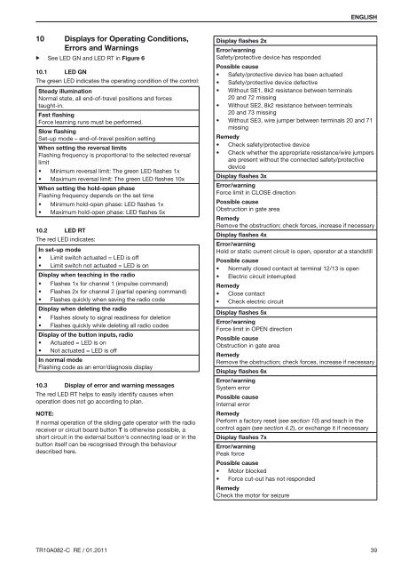
ENGLISH10 Displays for Operating Conditions,Errors and Warnings▶ See LED GN and LED RT in Figure 610.1 LED GNThe green LED indicates the operating condition of the control:Steady illuminationNormal state, all end-of-travel positions and forcestaught-in.Fast flashingForce learning runs must be performed.Slow flashingSet-up mode – end-of-travel position settingWhen setting the reversal limitsFlashing frequency is proportional to the selected reversallimit• Minimum reversal limit: The green LED flashes 1x• Maximum reversal limit: The green LED flashes 10xWhen setting the hold-open phaseFlashing frequency depends on the set time• Minimum hold-open phase: LED flashes 1x• Maximum hold-open phase: LED flashes 5x10.2 LED RTThe red LED indicates:In set-up mode• Limit switch actuated = LED is off• Limit switch not actuated = LED is onDisplay when teaching in the radio• Flashes 1x for channel 1 (impulse command)• Flashes 2x for channel 2 (partial opening command)• Flashes quickly when saving the radio codeDisplay when deleting the radio• Flashes slowly to signal readiness for deletion• Flashes quickly while deleting all radio codesDisplay of the button inputs, radio• Actuated = LED is on• Not actuated = LED is offIn normal modeFlashing code as an error/diagnosis display10.3 Display of error and warning messagesThe red LED RT helps to easily identify causes whenoperation does not go according to plan.NOTE:If normal operation of the sliding gate operator with the radioreceiver or circuit board button T is otherwise possible, ashort circuit in the external button's connecting lead or in thebutton itself can be recognised through the behaviourdescribed here.Display flashes 2xError/warningSafety/protective device has respondedPossible cause• Safety/protective device has been actuated• Safety/protective device defective• Without SE1, 8k2 resistance between terminals20 and 72 missing• Without SE2, 8k2 resistance between terminals20 and 73 missing• Without SE3, wire jumper between terminals 20 and 71missingRemedy• Check safety/protective device• Check whether the appropriate resistance/wire jumpersare present without the connected safety/protectivedeviceDisplay flashes 3xError/warningForce limit in CLOSE directionPossible causeObstruction in gate areaRemedyRemove the obstruction; check forces, increase if necessaryDisplay flashes 4xError/warningHold or static current circuit is open, operator at a standstillPossible cause• Normally closed contact at terminal 12/13 is open• Electric circuit interruptedRemedy• Close contact• Check electric circuitDisplay flashes 5xError/warningForce limit in OPEN directionPossible causeObstruction in gate areaRemedyRemove the obstruction; check forces, increase if necessaryDisplay flashes 6xError/warningSystem errorPossible causeInternal errorRemedyPerform a factory reset (see section 10) and teach in thecontrol again (see section 4.2), or exchange it if necessaryDisplay flashes 7xError/warningPeak forcePossible cause• Motor blocked• Force cut-out has not respondedRemedyCheck the motor for seizureTR10A082-C RE / 01.2011 39


