Montaje y uso Assembly and use Montage et utilisation ... - Roca
Montaje y uso Assembly and use Montage et utilisation ... - Roca
Montaje y uso Assembly and use Montage et utilisation ... - Roca

You also want an ePaper? Increase the reach of your titles
YUMPU automatically turns print PDFs into web optimized ePapers that Google loves.
Fig. BFig. C3
DINHALT:A) Bauteile des Artikels . . . . . . . . . . . . . . . . . . . . . . . . . . . . 2-3B) Technische Informationen . . . . . . . . . . . . . . . . . . . . . . . . . 14C) <strong>Montage</strong> . . . . . . . . . . . . . . . . . . . . . . . . . . . . . . . . . . . . . . 14D) Hinweise für den Gebrauch . . . . . . . . . . . . . . . . . . . . . . . . 15E) Fehlersuche . . . . . . . . . . . . . . . . . . . . . . . . . . . . . . . . . . . 15F) <strong>Montage</strong>zeichnung . . . . . . . . . . . . . . . . . . . . . . . . . . . . 25-26UKCONTENTS:A) Composition . . . . . . . . . . . . . . . . . . . . . . . . . . . . . . . . . 2-3B) Technical information . . . . . . . . . . . . . . . . . . . . . . . . . . . . 17C) Installation . . . . . . . . . . . . . . . . . . . . . . . . . . . . . . . . . . . 17D) Tips on <strong>use</strong> . . . . . . . . . . . . . . . . . . . . . . . . . . . . . . . . . . . 18E) Troubleshooting . . . . . . . . . . . . . . . . . . . . . . . . . . . . . . . . 18F) <strong>Assembly</strong> diagram . . . . . . . . . . . . . . . . . . . . . . . . . . . 25-26ISOMMARIO:A) Composizione articolo . . . . . . . . . . . . . . . . . . . . . . . . . . . 2-3B) Informazioni tecniche . . . . . . . . . . . . . . . . . . . . . . . . . . . . 20C) Installazione . . . . . . . . . . . . . . . . . . . . . . . . . . . . . . . . . . . 20D) Consigli per l’<strong>uso</strong> . . . . . . . . . . . . . . . . . . . . . . . . . . . . . . . 21E) Diagnostica . . . . . . . . . . . . . . . . . . . . . . . . . . . . . . . . . . . . 21F) Schema di montaggio . . . . . . . . . . . . . . . . . . . . . . . . . 25-264
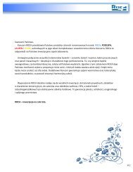
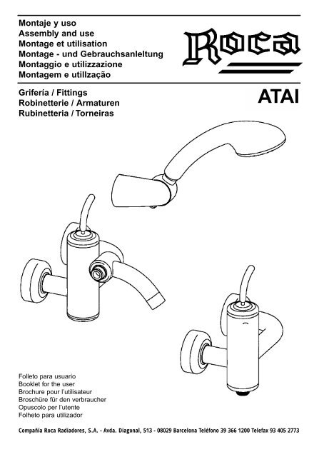
INFORMACIÓN TÉCNICA:Despiece (fig. A)1. Palanca2. Tornillo3. Disco deslizante4. Junta de teflón5. Tapón6. Junta tórica del cartucho7. Cartucho8. Manguitos9. Muelles10. Cuerpo interior11. Junta tórica12. Junta tórica13. Cuerpo exterior14. Tuerca15. Junta tórica16. Alojamiento17. Junta de estanquidad18. Junta de estanquidad19. Cubierta20. Anillo para el vástagoexcéntrico21. Vástago excéntrico22. Pasador de encaste23. Tapón24. Inversor25. Junta tórica26. Fijación del aireador27. Aireador28. Flexible29. Dúplex30. AlcachofaSuministro Recomendado Máxima MinimaTemperatura del agua caliente 65° 80° 15°Presión de trabajo 3 BAR 5 BAR 0.5 BARSi la presión de trabajo es superior a 5 bar, recomendamos utilizar un regulador depresion. Este grifo no es compatible con calentadores de agua instantáneos de bajapresión.RECOMENDACIONES DE MONTAJE:Importante: el agua caliente debe conectarse al tubo izquierdo, y la fría al derecho.INSTALACION:Cierre la llave de paso del agua y desmonte el grifo antiguo.Limpie bien las roscas del conducto de alimentación.Instrucciones para el correcto montaje:Fig. DMonte el vástago excéntrico -21- por el lado curvo G 1/2”. Utilice teflón u otro materialque garantice la estanquidad entre las fijaciones murales y este vástago.Fig. EInserte los vástagos excéntricos -21- en sus alojamientos con la rosca a idéntica profundidad,manteniendo una separación de 150 mm entre los centros (la máximadesalineación de las fijaciones murales es de ± 16 mm). Asegúrese de que los dosvástagos están alineados, de modo que el grifo quede perfectamente colocado.5
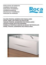
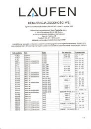
Fig. FMonte las juntas -20- en la parte circular de los vástagos -21-.Fig. HConecte el cuerpo del grifo utiliz<strong>and</strong>o la tuerca -14- y coloc<strong>and</strong>o la junta -17- entre medio.Fig. IDeslice las cubiertas contra la pared. Abra el grifo y asegúrese de que el mezcladorfunciona correctamente y que no pierde agua por ninguno de sus componentes. Paraabrir el grifo, empuje la palanca hacia adelante, a la izquierda para que salga aguacaliente y a la derecha para que salga agua fría. Para cerrar el grifo, empuje la palancahacia atrás. Con el mezclador conectado, compruebe el correcto funcionamientodel inversor. Levant<strong>and</strong>o el pomo -24.1- se desvía el caudal al teléfono de la ducha..Este inversor está provisto de un bloqueo que funciona elev<strong>and</strong>o el pomo del inversory girándolo 90 grados. Para desbloquearlo, basta con girarlo otros 90 grados.RECOMENDACIONES DE USO:Para limpiar piezas cromadas o con otros acabados, utilice una solución jabonosaaplicada con una esponja o un paño suave. Para limpiar el aireador, utilice un productoanti-cal líquido.IMPORTANTE: NO UTILICE abrasivos o productos con un alto grado de acidez.LOCALIZACIÓN DE AVERÍAS:PROBLEMA POSIBLES CAUSAS SOLUCIONESReducción notable del caudal • La presión es insuficiente • Compruebe el sistema aguas arriba• El aireador está obstruido • Limpie el aireador• El aireadorr está d<strong>et</strong>eriorado • Cambie el aireadorFuga de agua por debajo • El cartucho no está bien • Apri<strong>et</strong>e la tuerca anularde la palanca apr<strong>et</strong>ado • Compruebe el estado de las juntas• La junta base o las juntas tóricas (límpielas o cámbielas)están d<strong>et</strong>erioradas• Golpe de ari<strong>et</strong>e en el sistema• La temperatura del agua esexcesiva (más de 80°)Avería o fuga de agua en • La junta de estanquidad del • Desmonte y limpie las piezasel inversor inversor está d<strong>et</strong>eriorada a las que afecta esta junta ocambie el inversor compl<strong>et</strong>o.Fuga de agua en los tapones • Las juntas de estanquidad de • Cierre los tapones o cambielos tapones están d<strong>et</strong>erioradas las juntas.CAMBIO DEL CARTUCHO (Fig. B):Afloje el pasador de encaste -2- y extraiga la palanca -1- y el disco -3-; afloje el tapón-5- extraiga el cartucho -7-.Para volver a montar, siga el mismo procedimiento a la inversa, limpi<strong>and</strong>o con cui-6
dado las superficies que entran en contacto con los casquillos -8- y las juntas tóricas-6- y -11-.CAMBIO DEL INVERSOR (Fig. C):En caso de avería, extraiga el rácor -24.9- con una llave hexagonal (ES12), r<strong>et</strong>ire elanillo de ajuste forzado -24.7- con un destornillador de 2 mm. Tire del pomo haciaarriba -24.1- con cuidado de no perder las piezas que se desmontarán automáticamente,es decir, las dos ar<strong>and</strong>elas -24.5-, la junta de estanquidad -24.6- y el muelle-24.4-. Para volver a montar, siga el procedimiento a la inversa después de limpiarbien las juntas de estanquidad y aplicar una fina capa de grasa lubricante, si es necesario.CAMBIO DEL AIREADOR (Fig. C):Para desmontar el aireador -27-, desenrosque la tuerca anular -27.3- y limpie bien elfiltro -27.2-. Vuelva a montar el atomizador siguiendo el procedimiento a la inversa, yteniendo cuidado de colocar la junta -27.1- en la posición correcta.7
INFORMAÇÕES TÉCNICAS:Composição (fig. A)1. Pega2. Paraf<strong>uso</strong>3. Disco deslizante4. Anel de teflon5. Tampa da var<strong>et</strong>a6. O-ring do cartucho7. Cartucho8. Casquilhos9. Molas10. Corpo interno11. O-ring12. O-ring13. Corpo externo14. Tampa15. O-ring16. Alojamento17. Vedante18. Vedante19. Cobertura20. Anel para derivaçãoexcêntrica21. Derivação excêntrica22. Bucha23. Tampa inferior24. Inversor25. O-ring26. Acessório do arejador27. Arejador28. Flexível29. Duplex30. DucheFornecimento Recomendada Máximo MínimoTemperatura da água quente 65° 80° 15°Pressão de funcionamento 3 BAR 5 BAR 0.5 BARSe a pressão de funcionamento for superior a 5 BAR, recomendamos a utilização deum redutor de pressão. Esta torneira não é compatível com a utilização de aquecedoresde água quente instantâneos de pressão baixa .CONSELHOS DE INSTALAÇÃO:Importante: a água quente tem que estar ligada ao cano esquerdo, a água friaao cano direito.INSTALAÇÃO:Depois de desligar das linhas de alimentação, desmonte a torneira antiga.Limpe muito bem as roscas das linhas de alimentação.Instruções para uma instalação correcta:Fig. DColoque na derivação excêntrica -21- do lado inclinado G1/2” – algum teflon ou outromaterial que garanta a vedação entre as ligações à parede e a derivação.Fig. EAparaf<strong>use</strong> as derivações excêntricas -21- nos seus alojamentos à mesma profundidade,mantendo uma distância de 150 mm entre os centros (o desalinhamento máximode ligações à parede é +/- 16 mm). Certifique-se de que as duas derivações8
estão alinhadas de modo a que a torneira fique perfeitamente posicionada.Fig. FAdapte os anéis -20- à parte circular das derivações -21-.Fig. HLigue o corpo utiliz<strong>and</strong>o a tampa -14- coloc<strong>and</strong>o o vedante -17- entre elas.Fig. IDeslize as coberturas na direcção da parede. Ligue a água e verifique se o misturadorestá a funcionar correctamente e que não é d<strong>et</strong>ectada qualquer fuga em nenhumadas peças. Se puxar a pega ligará a água; posicion<strong>and</strong>o-a à esquerda sairá águaquente, e à direita, sairá água fria. Para desligar a água, basta empurrar a pega. Como misturador activo, verifique se a inversor está a funcionar correctamente.Levant<strong>and</strong>o o botão -24.1- desviará o fluxo para o chuveiro. Esta derivação está equipadacom um dispositivo de bloqueio que funciona através da elevação do botão dainversor e rod<strong>and</strong>o-o 90 graus. Para o libertar, basta rodá-lo mais 90 graus.CONSELHOS DE UTILIZAÇÃO:As peças cromadas ou as com outros acabamentos devem ser limpas apenas comsabão suave e água, utiliz<strong>and</strong>o uma esponja ou um pano macio. Para limpar o arejador,utilize apenas um produto antical líquido.IMPORTANTE: NÃO UTILIZE abrasivos nem produtos de acidez elevada.RESOLUÇÃO DE PROBLEMAS:PROBLEMA CAUSAS POSSÍVEIS SOLUÇÕESDiminuição notável no fluxo • Pressão insuficiente • Verificar o fluxo ascendente• Arejador obstruídodo sistema• Arejador d<strong>et</strong>eriorado• Limpar o arejador• Substituir o arejadorHá fuga de água sob a pega • O cartucho não está bem apertado • Apertar a porca anelar• Vedante da base ou O-rings • Verificar estado dos vedantesd<strong>et</strong>eriorados(limpá-los ou substituí-los)• Água a bater no sistema• Substituir cartucho• Temperatura da água demasiado • Verificar sistemaelevada (>80º)Mau funcionamento da • Vedante da derivação d<strong>et</strong>eriorado • Desmonte e limpe as peçasinversor ou fugavedadas ou substitua ainversor na totalidade.Fuga das tampas • Vedantes da tampa d<strong>et</strong>eriorados • Feche as tampas ou substituaos vedantesSUBSTITUIÇÃO DO CARTUCHO (Fig. B):Desaparaf<strong>use</strong> a bucha -2- e r<strong>et</strong>ire a pega -1- e o disco -3-; desaparaf<strong>use</strong> a tampa -9
5- e r<strong>et</strong>ire o cartucho -7-.Para montar, inverta os procedimentos, tendo o cuidado de limpar as superfícies emcontacto com os casquilhos -8- e os O-rings -6- e -11-.SUBSTITUIÇÃO DA INVERSOR (Fig. C):No caso de mau funcionamento, desaparaf<strong>use</strong> o acessório roscado -24.9- com umachave hexagonal (ES12), r<strong>et</strong>ire o anel de mola -24.7- com uma chave de paraf<strong>uso</strong>sde 2 mm. Puxe o botão para cima -24.1-, tendo cuidado para não soltar as peças queficarão automaticamente desmontadas, isto é, as duas anilhas -24.5-, o vedante -24.6- e a mola -24.4. Para montar, inverta os procedimentos depois de limpar cuidadosamenteos vedantes e de aplicar uma fina película de massa lubrificante, senecessário.SUBSTITUIÇÃO DO AREJADOR (Fig. C):Para desmontar o arejador -27-, desaparaf<strong>use</strong> na porca anelar -27.3- e r<strong>et</strong>ire do filtro-27.2- as impurezas. Volte a colocar o arejador realiz<strong>and</strong>o os procedimentos inversamente,tendo o cuidado de posicionar o vedante -27.1- correctamente.10
INFORMATIONS TECHNIQUES:Composition article (fig. A)1. man<strong>et</strong>te 11. joint torique 21. excentrique2. vis 12. joint torique 22. vis sans tête3. disque coulissant 13. corps extérieur 23. bouchon inférieur4. anneau téflon 14. calotte 24. déviateur5. bouchon tige 15. joint torique 25. joint torique6. joint torique cartouche 16. siège 26. raccord pour aérateur7. cartouche 17. joint 27. aérateur8. douilles 18. joint 28. flexible9. ressorts 19. rosace 29. duplex10. corps intérieur 20. anneau pour excentrique 30. showerAlimentation Recomm<strong>and</strong>ée Maximum MinimumTempérature eau chaude 65° 80° 15°Pression dynamique 3 BAR 5 BAR 0.5 BAREn cas de pression dynamique supérieure à 5 Bar, nous conseillons d’utiliser unréducteur de pression. C<strong>et</strong>te robin<strong>et</strong>terie est incompatible avec l’<strong>utilisation</strong> d’appareilde production d’eau chaude basse pression (réservoir sans pression ou chauffe-eauà écoulement libre).CONSEILS D’INSTALLATION:Important: le branchement d’eau chaude doit être réalisé à gauche, celui del’eau froide à droiteINSTALLATION:Après avoir coupé d’alimentation principale, démonter l’ancien robin<strong>et</strong>.N<strong>et</strong>toyer scrupule<strong>use</strong>ment les fil<strong>et</strong>s de l’alimentation principale.Instructions pour une installation correcte:Fig. DPositionner sur la tige excentrique -21- du côté fil<strong>et</strong>é G1/2” du téflon ou autre matériauapproprié à garantir l’étanchéité entre les raccords muraux <strong>et</strong> ce dernier.Fig. EVisser les tiges excentriques -21- dans leurs sièges muraux à la même profondeur <strong>et</strong>en conservant l’entraxe de 150mm (désaxage maxi. raccords muraux +/- 16mm).Vérifier que les deux tiges soient alignées pour garantir au robin<strong>et</strong> une position correcte.11
Fig. FAppliquer les anneaux -20- sur la partie circulaire des tiges -21-.Fig. HRelier le corp robin<strong>et</strong> dernier au moyen de la calotte -14- en interposant le joint -17.Fig. IFaire glisser les rosaces jusqu’en butée sur le mur. Ouvrir l’eau <strong>et</strong> vérifier le fonctionnementcorrect du mitigeur ainsi que l’étanchéité parfaite de toutes ses pièces. Enpoussant la man<strong>et</strong>te, on obtient l’ouverture de l’eau. En l’orientant vers la gauche,l’eau devient plus chaude <strong>et</strong> vers la droite elle devient plus froide. Pour fermer l’eau,il suffit de tirer la man<strong>et</strong>te. A mitigeur ouvert, vérifier le fonctionnement correct dudéviateur. En soulevant le pommeau -24.1-, le débit est dévié vers la douch<strong>et</strong>te. Ledéviateur en question est équipé d’un dispositif qui s’insère simplement en soulevant<strong>et</strong> en tournant de 90 degrés environ le pommeau du déviateur; pour le débloquer, ilsuffit de le tourner encore de 90 degrés.ENTRETIEN DE LA ROBINETTERIE:Le n<strong>et</strong>toyage des parties en chrome ou autres décors uniquement á l’eau savonne<strong>use</strong>avec une éponge ou en chiffon doux. Pour le n<strong>et</strong>toyage de l’aérateur utiliser uniquementun détartrant liquide ou du vinaigre chaud.ATTENTION: ne pas utiliser des produits abrasifs ou tout autre produit tropacide.DIAGNOSTIC DE PANNE, SOLUTIONS:PROBLÈMES CAUSES POSSIBLES REMÈDESGr<strong>and</strong>e diminution de • Pression d’alimentation • Vérifier l’installation en amontdébitinsuffisante• Aérateur obstrué• N<strong>et</strong>toyer l’aérateur• Aérateur détérioré• Remplacer l’aérateurPerte d’eau sous le • Cartouche insuffisamment serrée • Fermer la bague de serragelevier • Joint de base ou torique détériorés • Vérifier l’état des joints• Coups de bélier sur l’installation (n<strong>et</strong>toyage ou remplacement)• Température de l’eau trop• Remplacer la cartoucheélevée (>80º)• Vérifier l’installationMauvais fonctionnement • Joint du déviateur détérioré • Démonter <strong>et</strong> n<strong>et</strong>toyerdu déviateur o<strong>uso</strong>igne<strong>use</strong>ment les pièceséventuelles fuitesd’étanchéité ou bienremplacer complètement ledéviateurFuites d’eau des calottes • Joints dans les calottes détériorés • Fermer les calottes ou bienremplacer les joints12
REMPLACEMENT DE LA CARTOUCHE (Fig. B):Dévisser la vis sans tête -2- <strong>et</strong> enlever la man<strong>et</strong>te -1- <strong>et</strong> le disque -3-; dévisser lebouchon -5- <strong>et</strong> extraire la cartouche -7-. Pour le montage, procéder dans le sensinverse sans oublier de n<strong>et</strong>toyer soigne<strong>use</strong>ment la surface sur laquelle agissent lesdouilles d’étanchéité -8 <strong>et</strong> les joints toriques -6- <strong>et</strong> -11- .REMPLACEMENT DU DEVIATEUR (FIG.C):En cas de mauvais fonctionnement, dévisser le raccord fil<strong>et</strong>é -24.9- avec une cléhexagonale (ES12) ; enlever le seeger -24.7- avec un tournevis plat de 2mm. Tirer lepommeau -24.1- vers le haut en ayant soin de ne pas perdre les différentes piècesqui se démonteront automatiquement telles que les deux rondelles -24.5- le joint -24.6- <strong>et</strong> le ressort -24.4- . Pour le montage, procéder dans le sens inverse après avoirsoigne<strong>use</strong>ment n<strong>et</strong>toyé les joints <strong>et</strong> éventuellement ajouté un léger voile de graisselubrifiante.REMPLACEMENT DE L’AERATEUR (Fig. C):Pour procéder au démontage de l’aérateur -27-, il faut dévisser le corps -27.3- <strong>et</strong> n<strong>et</strong>toyerle filtre -27.2- des impur<strong>et</strong>és. Remonter l’aérateur en procédant en sens inverseen s’assurant de positionner le joint –27.1- de façon correcte.13
TECHNISCHE INFORMATIONEN:Bauteile des Artikels (fig. A)1. Griff 11. O-Ring 21. Exzenterschaft2. Schraube 12. O-Ring 22. Gewindestift3. Gleitscheibe 13. Außenkorpus 23. Unterer Verschluß4. Teflonring 14. Kalotte 24. Umsteller5. Stabverschluß 15. O-Ring 25. O-Ring6. O-Ring für die Kartusche 16. Aufnahme 26. Luftsprudlerfitting7. Kartusche 17. Dichtung 27. Luftsprudler8. Hülsen 18. Dichtung 28. Duschschlauch9. Federn 19. Ros<strong>et</strong>te 29. Duplex10. Innenkorpus 20. Ring für den Exzenterschaft 30. H<strong>and</strong>duscheZulauf Empfehlung Maximum MinimumWarmwassertemperatur 65° 80° 15°B<strong>et</strong>riebsdruck 3 BAR 5 BAR 0.5 BARBei B<strong>et</strong>riebsdrücken über 5 bar wird der Einsatz eines Druckminderventils empfohlen.Diese Armatur ist nicht für den Einsatz mit Durchlauferhitzern mitNiederdruckb<strong>et</strong>rieb geeign<strong>et</strong>.MONTAGE:Wichtig: Das Warmwasser ist an die linke Leitung und das Kaltwasser an dierechte Leitung anzuschließen.MONTAGE:Nachdem das Wasser an der Hauptversorgungsstelle abgestellt wurde, ist die alteArmatur abzubauen.Die Gewinde der Zulaufleitung sind gründlich zu reinigen.Anweisungen für eine richtige <strong>Montage</strong>:Abb. DDen Exzenterschaft (21) am Gewindeabschnitt G1/2“ mit Teflon oder einem <strong>and</strong>erenMaterial versehen, das die Dichtigkeit zwischen den W<strong>and</strong>anschlüssen und demSchaft gewährleist<strong>et</strong>.Abb. EDie Exzenterschäfte (21) in die hierfür vorgesehenen W<strong>and</strong>aufnahmen mit der gleichenTiefe und einem Abst<strong>and</strong> vonein<strong>and</strong>er von 150 mm (max. Achsabweichung derW<strong>and</strong>anschlüsse +/- 16 mm) einschrauben. Es ist sicherzustellen, daß die Schäfteauf der gleichen Achse liegen, um eine ordnungsgemäße Lage der Armatur zugewährleisten.14
Abb. FDie Ringe (20) am runden Abschnitt der Schäfte (21) anbringen.Abb. HDen armaturen kurpus mittels der Kalotte (14) mit zwischengelegter Dichtung (17) anschließen.Abb. IDie Ros<strong>et</strong>ten bis zum Anschlag an die W<strong>and</strong> führen. Die Wasserzufuhr anstellen unddie einw<strong>and</strong>freie Funktion der Armatur sowie die Dichtigkeit aller ihrer Best<strong>and</strong>teilekontrollieren. Durch Herunterdrücken des Griffes wird die Wasserzufuhr geöffn<strong>et</strong>,durch Verdrehen des Griffes nach links bzw. rechts läuft wärmeres bzw. kälteresWasser zu. Zum Schließen des Wasserzulaufs ist der Griff nach oben zu ziehen. Beigeöffn<strong>et</strong>er Armatur die einw<strong>and</strong>freie Funktionsweise des Umstellers kontrollieren. BeiHochziehen des Knaufs (24.1) wird der Wasserstrom zur Bra<strong>use</strong> geleit<strong>et</strong>. Der b<strong>et</strong>reffendeUmsteller ist mit einer Vorrichtung versehen, die sich durch Hochziehen undVerdrehen des Umstellerknaufs um ca. 90 Grad einschalt<strong>et</strong>, zur Abschaltung brauchtder Knauf nur um weitere 90 Grad verdreht zu werden.HINWEISE FÜR DEN GEBRAUCH:Die Reinigung der Teile mit Verchromungen oder <strong>and</strong>erweitigen Oberflächenverarbeitungendarf nur mit Wasser und neutraler Seife unter Verwendung eines Schwamms oder eines weichenLappens erfolgen. Zur Reinigung des Luftsprudlers ist ausschließlich ein flüssigerKalkentferner zu verwenden.ACHTUNG, KEINE scheuernden Produkte bzw. Produkte mit einem zu hohenSäuregehalt verwenden.FEHLERSUCHE UND – ABHILFE:PROBLEM MÖGLICHE URSACHEN ABHILFENWesentliche Verringerung • Ungenügender Förderdruck • Förderseitige Anlage kontrollierender Durchflußmenge • Luftsprudler verstopft • Luftsprudler reinigen• Luftsprudler schadhaft• Luftsprudler ers<strong>et</strong>zenAustr<strong>et</strong>endes Wasser • Kartusche nicht ausreichend festgezogen • Nutmutter festziehenunter dem Hebelgriff • Dichtungsscheibe oder O-Ringe • Zust<strong>and</strong> der Dichtungenbeschädigtkontrollieren (Reinigung• Wasserschläge in der Anlageoder Ersatz)• Wassertemperatur zu hoch (>80°C) • Kartusche auswechseln• Anlage überprüfenUmsteller funktioniert nicht • Dichtung des Umstellers abgenutzt • Dichtungsteile abbauen undeinw<strong>and</strong>frei oder eventuellsorgfältig reinigen oder denaustr<strong>et</strong>endes WasserUmsteller vollständig auswechselnAustr<strong>et</strong>endes Wasser an • Dichtungen der Kalotten abgenutzt • Kalotten abdichten oder DichtungenKalottenDichtungen auswechseln15
WECHSELN DER KARTUSCHE (Abb. B):Den Gewindestift (2) lösen und den Hebel (1) und die Scheibe (3) entfernen. DenVerschluß (5) abschrauben und die Kartusche (7) herausnehmen. Zur <strong>Montage</strong> inumgekehrter Reihenfolge vorgehen und hierbei darauf achten, daß dieDichtungsflächen der Dichtungshülsen (8) und der O-Ringe (6 und 11) gründlichgesäubert sind.WECHSELN DES UMSTELLERS (Abb. C):Bei nicht einw<strong>and</strong>freier Funktionsweise den Gewindestutzen (24.9) mit einemSechskantschlüssel (ES12) abschrauben. Den Seegerring (24.7) mit einem 2-mm-Schraubenzieher entfernen. Den Knauf (24.1) nach oben ziehen und darauf achten,daß hierbei nicht die <strong>and</strong>eren Teile wie die beiden Unterlegscheiben (24.5), dieDichtung (24.6) und die Feder (24.4) verlorengehen. Zur <strong>Montage</strong> in umgekehrterReihenfolge vorgehen, nachdem die Dichtungen sorgfältig gesäubert wurden undeventuell ein leichter Schmiermittelfilm aufgebracht wurde.WECHSEL DES LUFTSPRUDLERS (Abb. C):Zum Abbau des Luftsprudlers (27) ist die Nutmutter (27.3) abzuschrauben und derFilter (27.2) von den Verunreinigungen zu säubern. Den Luftsprudler wie oben in derumgekehrten Reihenfolge wieder anbauen und sich vergewissern, daß die Dichtung(27.1) wieder richtig einges<strong>et</strong>zt ist.16
TECHNICAL INFORMATION:Composition (fig. A)1. h<strong>and</strong>le 11. O-ring 21. eccentric shank2. screw 12. O-ring 22. dowel3. sliding disc 13. external body 23. lower cap4. teflon ring 14. cap 24. shunt5. rod cap 15. O-ring 25. O-ring6. cartridge O-ring 16. housing 26. aerator fitting7. cartridge 17. seal 27. aerator8. bushes 18. seal 28. flexible9. springs 19. cover 29. duplex10. internal body 20. ring for eccentric shank 30. showerSupply Recommended Maximum MinimumHot water temperature 65° 80° 15°Working pressure 3 BAR 5 BAR 0.5 BARIf working pressure is over 5 BAR, we recommend using a pressure reducer. This tapis not compatible with the <strong>use</strong> of low-pressure instantaneous hot water heaters.TIPS ON INSTALLATION:Important: the hot water must be connected to the left pipe, the cold water tothe right pipe.INSTALLATION:After shutting off the mains, disassemble the old tap.Clean the threads of the mains very well.Instructions for correct installation:Fig. DPosition onto the eccentric shank -21- from the bent side G1/2” - some teflon or othermaterial that will guarantee the seal b<strong>et</strong>ween the wall attachments <strong>and</strong> the shank.Fig. EScrew the eccentric shanks -21- into their housings to the same depth, maintaining adistance b<strong>et</strong>ween centres of 150 mm (max. misalignment of wall attachments is +/-16 mm). Make sure that the two shanks are aligned so that the tap will be perfectlypositioned.Fig. FFit the rings -20- onto the circular part of the shanks -21-.17
Fig.HConnect the tap body using the cap -14- placing the seal -17- b<strong>et</strong>ween them.Fig. ISlide the covers against the wall. Turn on the water <strong>and</strong> check that the mixer isworking properly <strong>and</strong> that no leakage is d<strong>et</strong>ected from any of its parts. Pulling theh<strong>and</strong>le will turn on the water; positioning it to the left will make the water hotter, to theright, colder. To turn off the water, simply push the h<strong>and</strong>le. With the mixer on, checkthat the shunt is working properly. Lifting the knob -24.1- will deviate the flow to theshower head. This shunt is equipped with a blocking device which works which worksby lifting the knob of the shunt <strong>and</strong> turning it 90 degrees. To release it, simply turn itan additional 90 degrees.TIPS ON USE:Chrome-plated parts or ones with other finishes are to be cleaned with mild soap<strong>and</strong> water only, using a sponge or soft cloth. To clean the aerator, <strong>use</strong> only a liquidlime-removal product.IMPORTANT: DO NOT USE abrasives or products with a high acidity.TROUBLESHOOTING:PROBLEM POSSIBLE CAUSES SOLUTIONSNotable decrease in flow • Water pressure insufficient• Check system upstream• Aerator clogged• Clean aerator• Aerator d<strong>et</strong>eriorated• Replace aeratorWater leaks from under • Cartridge not well tightened • Tighten ring nutthe h<strong>and</strong>le • Base seal or O-rings d<strong>et</strong>eriorated • Check condition of seals• Water hammering on system(clean or replace them)• Water temperature too high(>80°) • Replace cartridge• Check systemMalfunctioning of shunt • Shunt seal d<strong>et</strong>eriorated • Disassemble <strong>and</strong> clean the sealedor leakageparts or replac<strong>et</strong>he shunt compl<strong>et</strong>ely.Leakage from the caps • Cap seals d<strong>et</strong>eriorated • Close caps or replace seals.REPLACING THE CARTRIDGE (Fig. B):Unscrew the dowel -2- <strong>and</strong> take away the lever -1- <strong>and</strong> the disc -3-; unscrew the cap-5- <strong>and</strong> take out the cartridge -7-.To assemble, reverse the procedures, taking care to clean the surfaces in contact withthe bushes -8- <strong>and</strong> the O-rings -6- <strong>and</strong> -11- .18
REPLACING THE SHUNT (Fig. C):In case of a malfunction, unscrew the threaded fitting -24.9- with a hexagonal wrench(ES12), remove the snap ring -24.7- with a 2 mm screwdriver. Pull the knobupwards -24.1- be careful not to lose the parts which will be automatically disassembled,i.e., the two washers -24.5- the seal -24.6- <strong>and</strong> the spring -24.4- . Toassemble, reverse the procedures after carefully cleaning the seals <strong>and</strong> applying athin film of lubricating grease, if needed.REPLACING THE AERATOR (Fig. C):To disassemble the aerator -27-, unscrew the ring nut -27.3- <strong>and</strong> clean the filter -27.2- from any impurities. Fit back the aerator by carrying out the procedures in reverse,taking care to position the seal -27.1- correctly.19
INFORMAZIONI TECNICHE:Composizione articolo (fig. A)1. maniglia 11. oring 21. eccentrico2. vite 12. oring 22. grano3. disco scorrevole 13. corpo esterno 23. tappo inferiore4. anello teflon 14. calotta 24. deviatore5. tappo astina 15. oring 25. oring6. oring cartuccia 16. sede 26. raccordo per areatore7. cartuccia 17. rosone 27. areatore8. boccole 18. guarnizione 28. flessibile9. molle 19. rosone 29. duplex10. corpo interno 20. anello per eccentrico 30. docciaAlimentazione Raccom<strong>and</strong>ata Massima MinimaTemperatura acqua calda 65° 80° 15°Pressione di esercizio 3 BAR 5 BAR 0.5 BARIn caso di pressioni di esercizio superiori a 5 BAR, si consiglia l’<strong>uso</strong> di un riduttoredi pressione. Questa rubin<strong>et</strong>teria non e` compatibile con l’<strong>uso</strong> di boiler istantanei abassa pressione.CONSIGLI DI INSTALLAZIONE:Importante l’acqua calda deve essere collegata al tubo di sinistra, la fredda altubo di destra.INSTALLAZIONE:Dopo aver chi<strong>uso</strong> l’alimentazione principale, smontare il vecchio rubin<strong>et</strong>to.Pulire scrupolosamente i fil<strong>et</strong>ti dell` alimentazione principale.Istruzioni per una corr<strong>et</strong>ta installazione:Fig. DPosizionare sul gambo eccentrico -21- dal lato fil<strong>et</strong>tato G1/2” del teflon od altro materialeadatto a garantire la tenuta tra gli attacchi a muro e quest’ultimo.Fig. EAvvitare i gambi eccentrici -21- nelle apposite sedi a muro alla stessa profondita`mantenendo l’interasse di 150mm (disassamento Max attacchi a muro +/- 16mm).Assicurarsi che i due gambi siano allineato per garantire al rubin<strong>et</strong>to una posizionecorr<strong>et</strong>ta.20
Fig. FApplicare gli anelli -20- sulla parte circolare dei gambi -21-.Fig. HCollegare il rubin<strong>et</strong>to mediante la calotta -14- interponendo la guarnizione -17-.Fig. IFar scorrere i rosoni fino a battuta sul muro. Aprire l’acqua e verificare il corr<strong>et</strong>to funzionamentodel miscelatore nonche` la perf<strong>et</strong>ta tenuta di tutte le sue parti. Spingendola maniglia si ottiene l`apertura dell’acqua; orient<strong>and</strong>o la stessa verso sinistra si ottieneacqua piu` calda e verso destra acqua piu` fredda. Per chiudere l’acqua e` sufficient<strong>et</strong>irare la maniglia. A miscelatore aperto verificare il corr<strong>et</strong>to funzionamento deldeviatore. Sollev<strong>and</strong>o il pomolo -24.1- il flusso viene deviato verso la docc<strong>et</strong>ta. Ildeviatore in questione è dotato di un dispositivo che si inserisce semplicemente sollev<strong>and</strong>oe gir<strong>and</strong>o di c.a. 90 gradi il pomolo del deviatore, per sbloccarlo è sufficientegirarlo di altri 90 gradi.CONSIGLI PER L’USO:La pulizia delle parti cromate o finiture diverse deve essere eff<strong>et</strong>tuato esclusivamentecon acqua e sapone neutro utilizz<strong>and</strong>o una spugna o un panno morbido. Per lapulizia dell’aeratore utilizzare esclusivamente un anticalcare liquido.ATTENZIONE, NON utilizzare prodotti abrasivi o comunque troppo acidi.DIAGNOSTICA, SOLUZIONE DEI PROBLEMI:PROBLEMI POSSIBILI CAUSE SOLUZIONINotevole diminu- • Pressione di alimentazione insufficiente • Verificare l’impianto a montezione di portata • Areatore ostruito • Pulire l’areatore• Areatore d<strong>et</strong>eriorato• Sostituire l’areatorePerdita d’acqua da • Cartuccia non serrata a sufficienza • Chiudere la ghiera di serraggiosotto la maniglia • Guarnizione di base o • Verificare lo stato delleOrings d<strong>et</strong>erioratiguarnizioni (pulizia o sostituzione)• Colpi d`ari<strong>et</strong>e sull’mpianto• Sostituire la cartuccia• Temperatura dell’acqua troppo alta (>80º) • Verificare impiantoMal funzionamento del • Guarnizione del deviatore d<strong>et</strong>eriorata • Smontare, e pulire accuratamentedeviatore o eventualile parti in tenuta oppure sostituireperditecompl<strong>et</strong>amente il deviatorePerdita d’acqua dalle • Guarnizioni nelle calotte d<strong>et</strong>eriorate • Chiudere le calotte oppure sostituirecalottele guarnizioniSOSTITUZIONE DELLA CARTUCCIA (Fig. B):Svitare il grano -2- e togliere la leva -1- e il disco -3-; svitare il tappo -5- ed estrarre21
la cartuccia -7-. Per il montaggio, procedere in senso inverso facendo attenzione dipulire accuratamente la superficie dove agiscono le boccole di tenuta -8- e gli l’oring-6- e -11-.SOSTITUZIONE DEL DEVIATORE (Fig. C):In caso di malfunzionamento svitare il raccordo fil<strong>et</strong>tato -24.9- con una chiave esagonale(ES12) togliere il seger -24.7- con un cacciavite a taglio da 2mm. Tirare versol’alto il pomolo -24.1- avendo cura di non perdere le varie parti che si smonterannoautomaticamente quali le due rondelle -24.5- la guarnizione -24.6- e la molla -24.4-.Per il montaggio procedere in senso inverso dopo avere accuratamente pulito le guarnizionied eventualmente aggiunto un leggero velo di grasso lubrificante.SOSTITUZIONE DELL’AREATORE (Fig. C):A1 fine di procedere allo smontaggio dell’areatore -27- svitare la ghiera -27.3- e pulireil filtro -27.2- dalle impurità rimontare l’areatore procedendo in senso inverso assicur<strong>and</strong>osidi aver posizionato la guarnizione -27.1- in modo corr<strong>et</strong>to.22
Fig. DFig. EFig. F25
Fig. GFig. HFig. I26
VPC0502021450