volkswagen lt 35 2.5 sdi - Giordano Benicchi
volkswagen lt 35 2.5 sdi - Giordano Benicchi
volkswagen lt 35 2.5 sdi - Giordano Benicchi

You also want an ePaper? Increase the reach of your titles
YUMPU automatically turns print PDFs into web optimized ePapers that Google loves.
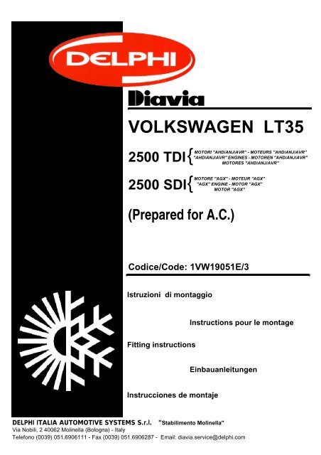
VOLKSWAGEN LT<strong>35</strong><br />
2500 TDI<br />
2500 SDI<br />
{<br />
{<br />
(Prepared for A.C.)<br />
MOTORI "AHD/ANJ/AVR" - MOTEURS "AHD/ANJ/AVR"<br />
"AHD/ANJ/AVR" ENGINES - MOTOREN "AHD/ANJ/AVR"<br />
MOTORES "AHD/ANJ/AVR"<br />
MOTORE "AGX" - MOTEUR "AGX"<br />
"AGX" ENGINE - MOTOR "AGX"<br />
MOTOR "AGX"<br />
Codice/Code: 1VW19051E/3<br />
Istruzioni di montaggio<br />
Instructions pour le montage<br />
Fitting instructions<br />
Einbauanleitungen<br />
Instrucciones de montaje<br />
DELPHI ITALIA AUTOMOTIVE SYSTEMS S.r.l. "Stabilimento Molinella"<br />
Via Nobili, 2 40062 Molinella (Bologna) - Italy<br />
Telefono (0039) 051.6906111 - Fax (0039) 051.6906287 - Email: diavia.service@delphi.com
PRESCRIZIONI PER IL MONTAGGIO DELL’IMPIANTO A/C DIAVIA OBBLIGATORIE PER IL TECNICO INSTALLATORE, IL QUALE, NEL CASO DI LORO<br />
INOSSERVANZA, SARÀ DIRETTAMENTE ED ESCLUSIVAMENTE RESPONSABILE VERSO IL CLIENTE:<br />
1 verificare il corretto serraggio della bulloneria fornita e rimossa e comunque di tutte le parti interessate al montaggio dell’impianto A/C;<br />
2 verificare che non ci siano perdite d’acqua, olio e aria su motore, freni, servosterzo, servofreno, ecc.;<br />
3 verificare tutti i livelli dei liquidi. Qualora venga rimosso il radiatore acqua, ricaricare nel circuito lo stesso liquido scaricato e, se è necessario un rabbocco,<br />
aggiungere il liquido anticongelante prescritto. Assicurarsi ino<strong>lt</strong>re che lo spurgo aria sia fatto come prescritto dal costruttore;<br />
4 accertarsi della giusta tensione di tutte le cinghie, e verificare lo stato di usura di quelle non sostituite;<br />
5 verificare che non si abbiano interferenze critiche in qualunque condizione di funzionamento. In particolare accertarsi che siano garantite distanze di sicurezza<br />
fra tutti i particolari soggetti a movimento relativo;<br />
6 garantirsi che non si abbiano fregamenti con conseguente usura tra le parti mediante un corretto serraggio e posizionamento delle stesse;<br />
7 assicurarsi del corretto isolamento elettrico, della corretta installazione dei fusibili e di tutte le parti dell’impianto elettrico;<br />
8 dopo aver effettuato la carica del refrigerante effettuare una accurata ricerca di eventuali perdite di gas;<br />
9 eseguire comunque ogni operazione secondo norme di buona tecnica;<br />
10 se durante l’operazione di installazione dell’impianto, vengono praticati fori o tagli, è obbligatorio proteggere tali parti con prodotto antiruggine fornito con<br />
l’impianto.<br />
PRESCRIPTIONS POUR LE MONTAGE DE L’INSTALLATION A/C DIA-<br />
VIA OBLIGATOIRES POUR LE TECHNICIEN INSTALLATEUR, CAR<br />
S’IL NE LES OBSERVAIT PAS, IL SERAIT DIRECTEMENT ET EXCLU-<br />
SIVEMENT RESPONSABLE ENVERS LE CLIENT:<br />
1 vérifier que la boulonnerie fournie et déplacée ainsi que toutes les<br />
parties concernées par le montage de l’installation A/C soient serrées<br />
correctement;<br />
2 vérifier qu’il n’y ait pas de pertes d’eau d’huile et d’air sur le moteur,<br />
les freins, la servodirection, le servofrein, etc...;<br />
3 vérifier tous les niveaux des liquides. Au cas où le radiateur eau serait<br />
déplacé, recharger dans le circuit le même liquide que celui qui a été<br />
déchargé et si un remplissage est nécessaire, ajouter le liquide antigel<br />
prescrit. S’assurer en outre que la vidange air soit faite comme<br />
prescrit par le constructeur.<br />
4 s’assurer de la juste tension de toutes les courroies et vérifier l’état<br />
d’usure de celles qui n’ont pas été remplacées;<br />
5 vérifier qu’il n’y ait pas d’interférences critiques dans toutes les conditions<br />
de fonctionnement. S’assurer en particulier que les distances de<br />
sécurité entre toutes les pièces sujettes à un mouvement relatif soient<br />
respectées;<br />
6 s’assurer qu’il n’y ait pas de frottements provuquant l’usure entre les<br />
parties grâce au serrage et au positionnement corrects de celles-ci;<br />
7 s’assurer que l’isolation électrique, l’installation des fusibles et de toutes<br />
les parties de l’installation électrique soient correctes;<br />
8 après avoir effectué la charge du réfrigérant, effectuer une recherche<br />
minutieuse des pertes éventuelles de gas;<br />
9 de toute façon, effectuer toutes les opérations suivant les normes de<br />
la meilleure technique;<br />
10 si durant l’opération de mise en place de l’installation des trous et des<br />
coupes sont pratiquées, il est obligatoire de protéger ces parties avec<br />
le produit antirouille fourni avec l’installation.<br />
PRESCRIPTIONS FOR MOUNTING THE DIAVIA A/C SYSTEM TO BE<br />
FOLLOWED BY THE TECHNICIAN INSTALLING THE SYSTEM.<br />
SHOULD THEY NOT BE OBSERVED THE TECHNICIAN WILL BE DI-<br />
RECTLY AND EXCLUSIVELY RESPONSIBLE TO THE CLIENT.<br />
1 check the propper tightening of the supplied nuts and bo<strong>lt</strong>s and removal,<br />
and otherwise, of all parts involved in assembly of the A/C system;<br />
2 check that there are no water, oil or air leaks on the engine, brackes,<br />
power steering, power brakes, etc.;<br />
3 check the level of all liquids. Should the radiator water be removed, reload<br />
the same discharged water in the circuit and, if it is necessary to<br />
fill to the brim add the prescribed liquid anti-freeze. Furthermore, make<br />
sure that the air cleaning is carried out as prescribed by the builder;<br />
4 check the proper tension of all the be<strong>lt</strong>s and check the state of wear<br />
on those which have not been replaced;<br />
5 check that there is not critical interference under any function condition.<br />
In particular check that the safety distances between all parts<br />
subject to relative movement are guaranteed;<br />
6 ensure that there is no rubbing between parts with consequent wear<br />
by means of proper tightening and positioning of the parts themselves;<br />
7 check that electric insulation, fuse installation and all parts of the electrical<br />
system are correct;<br />
8 after having charged the coolant make a careful search for any leaks<br />
of gas;<br />
9 carry out all operations according to the rules of good technology;<br />
10 should any holes or cuts be made during installation of the system, it<br />
is absolutely necessary to protect such parts with the rust-proof product<br />
supplied with the system.<br />
VERBINDLICHE VORSCHRIFTEN FÜR DEN EINBAUTECHNIKER BEI<br />
NICHTBEACHTUNG ERLISCHT JEDER ANSPRUCH AUF GARANTIE<br />
UND ERSATZTEILLIEFERUNG<br />
1 Jede DIAVIA-Klimaanlage ist gemäß der beigefügten Einbauanleitung<br />
einzubauen;<br />
2 Bei allen Einbauteilen der Klimaanlage ist auf die vorgeschriebene<br />
Anbringung an den vorgesehenen Punkten zu achten, ebenso wie auf<br />
die erforderliche Bewegungsfreiheit der einzelnen Aggregatteile. Bei<br />
korrekter Positionierung und Befestigung der Teile sind Abnutzungen<br />
durch reibung ausgeschlossen. Eventuell auftretende Störungen sind<br />
unverzüglich zu überprüfen;<br />
3 Alle Einbauteile sowie die verwendeten Schrauben und Muttern sind<br />
auf ihre korrekte Spannung und festen Sitz hin zu überprüfen:<br />
4 Alle Teile der elektrischen Anlage sowie die Sicherungen sind auf Isolation<br />
und korrekte Installation hin zu überprüfen;<br />
5 Nach auffüllung der Klimaanlage mit dem Kä<strong>lt</strong>emittel muß die gesamte<br />
Anlage auf eventuelle Verluste von gas überprüft werden;<br />
6 Bei Inbetriebnahme der Klimaanlage ist die korrekte Spannung aller<br />
Keilriemen zu überprüfen. Nicht ersetzte Keilriemen sind auf ihre Abnutzung<br />
hin zu untersuchen;<br />
7 Nach Einbau der Klimaanlage ist zu überprüfen, daß Motor, Bremsen,<br />
Servolenkung und Servobremse keine Wasser-, Oel- oder Luftverluste<br />
aufweisen;<br />
8 Vor Übergabe des Wagens muß das Niveau aler Flüssigkeitsanzeigen<br />
uberprüft werden. Falls beim Klimaanlagen-Einbau der Wasserkühler<br />
ausgebaut wurde, ist die entnommene Flüssigkeit im Umlauf<br />
wieder aufzufüllen und das erforderliche Frostschutzmittel nachzufüllen;<br />
9 Im Falle daß während der Installation sarbeiten der Anlage Bohrungen<br />
oder Schnitte durchgeführt werden, ist es unbedingt notwendig,<br />
diese Teile mit dem bei der Anlage mit gelieferten Rostschutz mittel<br />
zu schützen.<br />
PRESCRIPTIONES PARA EL MONTAJE DE LA INSTALACION A/C<br />
DIAVIA OBLIGATORIAS PARA EL TECNICO INSTALADOR; EN CASO<br />
DE SUS INOBSERVANCIA, EL SERA DIRECTAMENTE Y EXCLUSIVA-<br />
MENTE RESPONSABLE HACIA EL CLIENTE<br />
1 verificad que los tornillos en dotación, los removidos y de todos modos<br />
todas las partes que se emplean para el montaje de la instalación<br />
A/C sean bién apretadas;<br />
2 verificad que no se producan pérdidas de agua, óleo y aire sobre el<br />
motor, los frenos, el servofreno, el servorodetes, etc.;<br />
3 verificad todos los niveles de los liquidos. En caso se remueva el radiador,<br />
de agua, recargad en el circuito el mismo liquido descargado,<br />
y si es necesario el relleno añadid el liquido anticongelamiento prescrito.<br />
Además, averiguad que el expurgo de aire sea hecho como<br />
está prescrito por el constructor;<br />
4 averiguad que todas las correas sean bien tendidas y verificad el<br />
estado de desgaste de las que no han sido sustituidas;<br />
5 verificad que no se producan graves interferencias en cualquier condición<br />
de funcionamiento. En particular verificad de que sean garantizadas<br />
las distancias de seguridad entre todos los sujetos particulares,<br />
con movimiento relativo;<br />
6 averiguad que no se producan fricaciones con consiguiente desgaste<br />
de las partes, apretándolas corectamente y poniendo esas mismas<br />
en posición corecta;<br />
7 verificad el corecto aislamiento eléctrico, la corecta instalación de los<br />
fusibles y de todas las partes de la instalación eléctrica;<br />
8 después de haber introducido el refrigerante, efectuad una búsqeda<br />
diligente acerca de posibles pérdidas de gas;<br />
9 de todos modos, efectuad cada operación según las normas comunes<br />
a los buenos técnicos;<br />
10 si durante la operación de puesta de la instalación se hacen agujeros<br />
o cortes les aconcejamos protejan esto puntos con un producto antioxido<br />
abastecido con la instalación.
auto air conditioners<br />
NOTE:<br />
Lo schema di montaggio illustra l'impianto AC e comprende a vo<strong>lt</strong>e dei componenti<br />
accessori (es. minimo veloce, radiatore, ecc.) che debbono però essere ordinati separatamente,<br />
in aggiunta all'impianto base, consu<strong>lt</strong>ando il ns. listino.<br />
Tutte le indicazioni relative alla DESTRA ed alla SINISTRA sono riferite al senso di<br />
marcia: SINISTRA = lato guida, DESTRA = lato passeggero.<br />
Tutti i numeri presenti nel testo e nelle figure, indicano componenti forniti del condizionatore<br />
e vanno pertanto riferiti ai kit di figg. 1, 2, 3, 3.1 e 4.<br />
Tutte le viti e i raccordi tubi gas vanno bloccati senza superare i valori massimi delle<br />
coppie di serraggio indicati nella tabella seguente, se non diversamente specificato<br />
nel testo.<br />
A montaggio u<strong>lt</strong>imato si consiglia di applicare sulle parti metalliche installate un prodotto<br />
spray trasparente, protettivo anticorrosione.<br />
Per il corretto funzionamento ed affidabilità delle cinghie installate, eseguire le seguenti<br />
operazioni:<br />
a) Avviare il motore con impianto A.C. inserito e dopo 15 minuti circa di funzionamento,<br />
ritensionare le cinghie.<br />
b) La stessa operazione di retensionamento va ripetuta dopo 1500 Km dalla installazione<br />
dell'impianto A.C.<br />
Nella vettura provvista di dispositivi di sicurezza tipo AIR BAG o PROCON-TEN® lo<br />
smontaggio di tali componenti deve essere effettuato attenendosi alle disposizioni<br />
delle rispettive case automobilistiche.<br />
La quantità di gas R134a necessaria per la carica dell'impianto è di Kg. 0,550 (±0,025).<br />
ANMERKUNG:<br />
Die Einbauanleitung beschreibt die Klimaanlage, in einigen Fällen gehören jedoch<br />
Bauteile hinzu (z.B. Leerlaufforrichtung, Kühler, Lüfter usw.) die separat zur Grundausstattung<br />
der Anlage zu bestellen sind, da es sich um Zusatzteile hande<strong>lt</strong>, siehe<br />
unsere Preisliste.<br />
Alle Hinweise auf RECHTS und LINKS beziehen sich auf die Fahrtrichtung: LINKS<br />
= Fahrerseite, RECHTS = Beifahrerseite.<br />
Alle Ziffern im Text und der Abbildung 1, 2, 3, 3.1 und 4 beziehen sich auf vorhandene<br />
Bestandteile des Bausatzes.<br />
Alle Schraub- und Schlauchverbindungen sind gemäß unten stehender Tabelle anzuziehen,<br />
falls nicht anders angegeben.<br />
Nach beendetem Einbau ist es ratsam auf die eingebauten Metal<strong>lt</strong>eile Schutzwachs<br />
aufzusprühen, um Rostbildung zu verhindern.<br />
Für Funktion und Lebensdauer der Keilriemen ist folgendes zu beachten:<br />
a) Den Motor mit eingescha<strong>lt</strong>eter Klimaanlage anlassen und nach ca. 15 Minuten<br />
der Funktion, die Riemen spannen.<br />
b) Nach 1500 Km. Riemen nach- spannen.<br />
Bei Fahrzeugen mit Sicherheitvorrichtung wie AIR BAG oder PROCON-TEN®, muß<br />
der Ausbau derselben, nur nach den Anleitungen der Automobilhäuser durchgeführt<br />
werden.<br />
Die notwendige Menge des gas R134a für die Auffüllung der Klimaanlage ist 0,550<br />
(±0,025) Kg.<br />
REMARQUE:<br />
Le manuel des instructions illustre l’équipement A.C. et il comprend quelque fois des<br />
composants accessoires (par ex. ralenti-accéléré, radiateur, ventilateur, etc) qui doivent<br />
cependant être commandés séparément, outre à l'installation de base, en consu<strong>lt</strong>ant<br />
notre catalogue.<br />
Toutes les indications de DROITE et de GAUCHE se référent à la direction de marche:<br />
GAUCHE = côté conducteur, DROITE = côté passager.<br />
Tous les numéros du texte et des figures indiquent les composants fournis du conditionneur.<br />
Ils doivent par conséquent être référés aux kits des figg. 1, 2, 3, 3.1 et 4.<br />
Tous les vis et les raccords des tuyaux gaz doivent être bloqués sans dépasser les<br />
valeurs maximum des couples de serrage indiqués dans le tableau suivant, si ce<br />
n'est pas spécifié différemment.<br />
Une fois le montage fini, on conseille d'appliquer un produit en spray transparent, de<br />
protection anticorrosif sur les parties métalliques installées.<br />
Pour obtenir le bon fonctionnement et la fiabilité des courroies installées, effectuer<br />
les opérations suivantes:<br />
a) Faire démarrer le moteur avec l'installation d'air conditionné insérée et après 15<br />
minutes environ, tendre à nouveau les courroies.<br />
b) Il faut répéter l'opération de nouvelle tension de la courroie après 1500 Km de la<br />
mise en place de l'installation.<br />
Sur les voitures munies des systèmes de sécurité type AIR BAG ou PROCON-<br />
TEN®, le démontage de ces composants doit être effectué en suivant scrupuleusement<br />
les dispositions de chaque Constructeur.<br />
La quantité de gaz R134a nécessaire pour charger l'équipement est de Kg.<br />
0,550(±0,025).<br />
NOTAS:<br />
El manual de instrucciones ilustra la instalación A.C. y a veces comprende componentes<br />
accesorios (ejemplo, minimo acelerado, radiador, ventilador etc.) que se deben<br />
ordernar separadamente, como agregado a la instalación base consu<strong>lt</strong>ando<br />
nuestro listin.<br />
Todas las indicaciones relativas a la DERECHA y a la IZQUIERDA se refieren al<br />
sentido de marcha: IZQUIERDA = lado conductor; DERECHA = lado pasajero.<br />
Todos los números presentes en el texto y en las figuras indican componentes abastecidos<br />
del equipo de aire acondicionado y se refieren a los kits de las figuras 1, 2,<br />
3, 3.1 y 4.<br />
Todos los tornillos y los racordes tubos gas tienen que ser bloqueados sin superar<br />
los valores máximos de las parejas de cerraje indicados por el cuadro que sigue, si<br />
no diversamente especificado.<br />
Una vez efectuado el montaje se aconseja aplicar en las paredes metálicas instaladas<br />
un producto spray trasparente, de protección antioxidante.<br />
Para la correcta puesta en marcha y fiabilidad de las correas montadas llevar a cabo<br />
las operaciones siguientes:<br />
a) Arrancar el motor con equipo aire acondicionado conectado y después de 15 minutos<br />
de funcionamiento, volver a tensar las correas.<br />
b) Hay que volver a repetir la misma operación de tensar la correa después de 1500<br />
Kms. a partir de montaje del equipo.<br />
En los coches provistos de dispositivos de seguridad tipo AIR BAG o PROCON-<br />
TEN® el desmontaje de tales componentes se debe efectuar ateniendose a las disposiciones<br />
de las respectivas casas automobilisticas.<br />
La cantidad de gas R134a necesaria para cargar el equipo es de Kg. 0,550 (±0,025).<br />
NOTE:<br />
This instruction manual illustrates the A.C. system and at times, includes accessories<br />
(eg. idle-speed device, radiator, fan, etc.). These parts, however, must be ordered<br />
separately from the basic kit, consu<strong>lt</strong> our parts list.<br />
All references to RIGHT and LEFT hand are related to driving direction: LEFT = driver's<br />
side, RIGHT = passenger's side.<br />
All numbers quoted in the next and under the photos refer to the components supplied<br />
of the air conditioning unit. One must therefore refer to the kits shown in fig. 1,<br />
2, 3, 3.1 and 4.<br />
All screws and gas pipes fittings must be locked without exceeding the maximum value<br />
of the driving torques indicated in the following table, if not otherwise.<br />
Once fitting has been completed spray an anticorrosive transparent product on the<br />
metal parts installed.<br />
To ensure functioning and reliability of installed be<strong>lt</strong>s, carry out the following procedures:<br />
a) Start motor with A.C. system switched on and after about 15 minutes adjust be<strong>lt</strong><br />
tension.<br />
b) The same adjustment procedure should be repeated after 1500 Km from the installation<br />
of the system.<br />
In those vehicles with AIR BAGS or PROCON-TEN® safety devices, these components<br />
must be removed carefully following the instructions given by the manifacturer.<br />
The quantity of gas R134a necessary for charging the system is Kg. 0.550 (±0.025).<br />
RACCORDO<br />
VALORI MASSIMI COPPIE DI SERRAGGIO<br />
PER RACCORDI TUBI GAS (in N.m.)<br />
RACCORD<br />
VALEURS MAXIMUM DES COUPLES DE SERRAGE<br />
POUR RACCORDS TUYAUX DU FREON (en N.m.)<br />
FITTINGS<br />
MAXIMUM VALUES OF THE DRIVING TORQUES<br />
FOR GAS PIPES FITTINGS (in N.m.)<br />
VERBINDUNG MAXIMUMWERT DER VERSCHRAUBUNGSPAARE FÜR DIE<br />
VERBINDUNGEN DER KÄLTEMITTELSCHLÄUCHE (in N.m.)<br />
RACORDE<br />
VALORES MAXIMOS PAREJAS DE CERRAJE<br />
PARA RACORDES TUBOS GAS (en N.m.)<br />
5/8" 15.4 ÷ 17<br />
3/4" 15.4 ÷ 17<br />
7/8" 24.4 ÷ 27<br />
1" 24.4 ÷ 27<br />
VALORI MASSIMI COPPIE DI SERRAGGIO PER VITI (in N.m.)<br />
VALEURS MAXIMUM DES COUPLES DE SERRAGE POUR LES VIS (en N.m.)<br />
MAXIMUM VALUES OF THE DRIVING TOURQUES FOR SCREWS (in N.m.)<br />
MAXIMUMWERT DER VERSCHRAUBUNGEN FÜR DIE SCHRAUBEN (in N.m.)<br />
VALORES MAXIMOS PAREJAS DE CERRAJE PARA TORNILLOS (en N.m.)<br />
Filettatura<br />
Filetage / Thread<br />
Gewinde / Filetadura<br />
Classe dell'acciaio della vite<br />
Classe de l'acier de la vis / Screw steel class<br />
Stahlklassifizierung der Schrauben / Clase del acero del tornillo<br />
5.8 8.8 10.9<br />
Apertura in chiave (mm)<br />
Ouverture en clef (mm))<br />
Wrench opening (mm)<br />
Schlüsselöffnung (mm)<br />
Abertura en llave (mm)<br />
M 4(x0.7) 1.8 2.9 4.2 7<br />
M 5(x0.8) 3.4 5.5 7.5 8<br />
M 6(x1) 6.00 10 13 10<br />
M 7(x1) 11 16 21 11<br />
M8(x1.25) 14 22 30 13<br />
M 8x1 15 23 32 13<br />
M10(x1.5) 27 45 61 17<br />
M10 x1,25 31 50 67 17<br />
M10 x1 33 53 71 17<br />
M12 x1.5 51 78 105 19<br />
M12 x1.25 60 94 125 19<br />
M12 x1.75 84.8 119 143 19<br />
M14 x1.5 80 120 165 22<br />
M16 x1.5 120 185 255 24<br />
M18 x1.5 165 265 <strong>35</strong>0 27<br />
M20 x1.5 225 360 490 30<br />
M22 x1.5 295 480 640 32<br />
M24 x2 390 610 805 36<br />
1
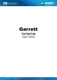
MATERIALE FORNITO / MATERIEL FOURNI / SUPPLIED MATERIAL / GELIEFERTES MATERIAL / MATERIAL ABASTECIDO<br />
FIG. 1<br />
I<br />
F<br />
GB<br />
D<br />
E<br />
Vista componenti montaggio compressore.<br />
Vue des composants pour le montage du compresseur.<br />
Compressor kit.<br />
Ansicht der Kompressoreinbauteile.<br />
Vista componentes montaje compresor.<br />
2
auto air conditioners<br />
ELENCO MATERIALE FORNITO (FIG. 1)<br />
LISTE DU MATERIEL FOURNI (FIG. 1) / LIST OF SUPPLIED MATERIALS (FIG. 1)<br />
VERZEICHNIS DES GELIEFERTEN MATERIALS (ABB. 1) / LISTA MATERIAL ABASTECIDO (FIG. 1)<br />
Codice<br />
Pos. Descrizione / Déscription / Description / Beschreibung / Descripción Kode<br />
Código<br />
5 Puleggia galoppino / Poulie galopin / Guide pulley / Leitrollen-Riemenscheibe / Polea tensor de correa 004032/1<br />
6 Perno puleggia galoppino / Pivot de galopin / Guide pulley pin / Leitrollen-Riemenscheibenbolzen / Perno polea tensor de correa 005052<br />
7 Staffa anteriore supporto compressore / Bride antérieure support compresseur / Front compressor support bracket /<br />
Vorderer Kompressor-Ha<strong>lt</strong>ebügel / Abrazadera anterior soporte compresor<br />
002892VW<br />
8 Staffa posteriore supporto compressore / Bride postérieure support compresseur / Rear compressor support bracket /<br />
Hinterer Kompressor-Ha<strong>lt</strong>ebügel / Abrazadera posterior soporte compresor<br />
002893VW/1<br />
9 Distanziale / Entretoise / Spacer / Abstandsstück / Distanciador Ø10xØ22x3 009448ZN<br />
10 Rondella piana / Rondelle plate / Plain washer / Flache U-Scheibe / Arandela plana Ø10 UNI 6592 —<br />
11 Cinghia compressore / Courroie du compresseur / Compressor be<strong>lt</strong> / Kompressoriemen / Correa compresor 6Kx2120 01<strong>35</strong>00<br />
13 Vite TE / Vis à tête à six pans / Hexagonal head screw / Sechskantschraube / Tornillo cabeza hexagonal M8x90 UNI 5737 —<br />
14 Vite TE / Vis à tête à six pans / Hexagonal head screw / Sechskantschraube / Tornillo cabeza hexagonal M10x<strong>35</strong> UNI 5739 —<br />
15 Vite TE / Vis à tête à six pans / Hexagonal head screw / Sechskantschraube / Tornillo cabeza hexagonal M10x60 UNI 5737 —<br />
16 Vite autofilettante TCC / Vis autotaradeuse à tête cylindrique avec calotte en forme de croix /<br />
Self-tapping raised cheese head screw / Selbstschneidende Linsen-Blechschraube mit Kreuzschlitz /<br />
Tornillo autoatornillable cabeza cilíndrica a forma de cruz 3,5x9,5 —<br />
17 Termostato / Thermostat / Thermostat / Thermostat / Termostato 068012/1<br />
18 Staffa termostato / Bride thermostat / Thermostat bracket / Thermostatha<strong>lt</strong>er / Abrazadera termostato 068048<br />
19 Pomello / Pommeau / Knob / Drehkopf / Pomo 068407<br />
20 Rondella dentellata / Rondelle dentelée / Notched washer / Zahnscheibe / Arandela dentada Ø12 DIN 6798 —<br />
21 Rondella ondulata / Rondelle ondulée / Corrugated washer / Gewel<strong>lt</strong>e U-Scheibe / Arandela ondulada Ø10 DIN 137B —<br />
22 Rondella elastica conica / Rondelle élastique conique / Conical elastic washer / Elastische Kegelscheibe /<br />
Arandela elástica cónica Ø8 108306<br />
24 Dado autobloccante / Ecrou autobloquant / Self-locking nut / Selbstsichernde Mutter / Tuerca autoblocante M10 UNI 7474 —<br />
26 Dado autobloccante / Ecrou autobloquant / Self-locking nut / Selbstsichernde Mutter / Tuerca autoblocante M8 UNI 7474 —<br />
27 Compressore / Compresseur / Compressor / Kompressor / Compresor 015109<br />
28 Gommino Ø3 / Pièce en caoutchouc Ø3 / Rubber lead Ø3 / Gummitülle Ø3 / Goma Ø3 069127<br />
30 Cablaggio per compressore / Câblage pour compresseur / Compressor wiring / Verkabelung für Kompressor /<br />
Cablaje para compressor 028839<br />
3
MATERIALE FORNITO / MATERIEL FOURNI / SUPPLIED MATERIAL / GELIEFERTES MATERIAL / MATERIAL ABASTECIDO<br />
FIG. 2<br />
I<br />
F<br />
GB<br />
D<br />
E<br />
Vista componenti montaggio condensatore, fi<strong>lt</strong>ro e accessori.<br />
Vue des composants pour le montage du condenseur - fi<strong>lt</strong>re et accessoires.<br />
Condenser-receiver drier and accessories kits.<br />
Einbauteile Kondensator-Fi<strong>lt</strong>er und Zubehörteile.<br />
Vista componentes montaje condensador - fi<strong>lt</strong>ro y accesorios.<br />
4
auto air conditioners<br />
ELENCO MATERIALE FORNITO (FIG. 2)<br />
LISTE DU MATERIEL FOURNI (FIG. 2) / LIST OF SUPPLIED MATERIALS (FIG. 2)<br />
VERZEICHNIS DES GELIEFERTEN MATERIALS (ABB. 2) / LISTA MATERIAL ABASTECIDO (FIG. 2)<br />
Codice<br />
Pos. Descrizione / Déscription / Description / Beschreibung / Descripción Kode<br />
Código<br />
31 Condensatore / Condenseur / Condenser / Kondensator / Condensador 022301OR<br />
32 Fi<strong>lt</strong>ro essiccatore / Fi<strong>lt</strong>re déshydrateur / Dehydrator receiver / Trocknerfi<strong>lt</strong>er / Fi<strong>lt</strong>ro secador 017050<br />
33 Vite TE / Vis six pans / Hexagonal head screw / Sechskantschraube / Tornillo cabeza hexagonal M6x16 —<br />
34 Staffa sinistra supporto condensatore / Etrier gauche condenseur / Condenser left bracket / Linker Kondensator-Ha<strong>lt</strong>erbügel /<br />
Soporte izquierdo del condensador 0812433<br />
<strong>35</strong> Staffa destra supporto condensatore / Etrier droit condenseur / Condenser right bracket / Rechter Kondensator-Ha<strong>lt</strong>erbügel /<br />
Soporte derecho del condensador 0812432<br />
36 Fascetta fermatubo / Collier de fixation tuyau / Hose clamp / Schlauchbinder-Schelle / Abrazadera bloquea tubo Ø18 0696<strong>35</strong><br />
37 Fascetta fermatubo / Collier de fixation tuyau / Hose clamp / Schlauchbinder-Schelle / Abrazadera bloquea tubo Ø22 069636<br />
38 Staffa supporto fi<strong>lt</strong>ro / Etrier fi<strong>lt</strong>re / Dehydrator receiver bracket / Fi<strong>lt</strong>er-Ha<strong>lt</strong>erbügel / Soporte de fi<strong>lt</strong>ro 0361229<br />
39 Rondella piana / Rondelle plate / Plain washer / Flache U-Scheibe / Arandela plana Ø6 —<br />
40 Dado autobloccante / Ecrou autobloquant / Self-locking nut / Selbstsichernde Mutter / Tuerca autobloqueante M6 —<br />
41 Fascetta fermatubo / Collier de fixation tuyau / Hose clamp / Schlauchbinder-Schelle / Abrazadera bloque tubo Ø24 069637<br />
42 Vite autofilettante TE / Vis autotaraudeuse six pans / Self-tapping hexagonal head screw / Selbstschneidende Sechskantschraube /<br />
Tornillo autorroscante cabeza hexagonal 4.2x13 —<br />
43 Pressostato / Pressostat / Pressure switch / Druckwächter / Presostato 043118<br />
44 Vite autofilettante TEI / Vis autotaraudeuse six pans fendue / Self-tapping hexagonal slotted screw /<br />
Gekerbte selbstschneidende Sechskantschraube / Tornillo autorroscante cabeza hexagonal con entalladura 6.3x16 —<br />
45 Staffa supporto Relais-Fusibili / Etrier relais-fusibles / Relay-fuse bracket / Relais-Schmelzsicherungs-Ha<strong>lt</strong>erbügel /<br />
Soporte de relé-fusibles 0682066<br />
46 Fascetta a strappo piccola / Collier Velcro petit / Small tear-off clamp / Kleine Abreisschelle / Banda de arrancar pequeña 069471<br />
47 Fasceta a strapo grande / Collier Velcro grand / Large tear-off clamp / Grosse Abreisschelle / Abrazadera a tirón larga 069029<br />
48 FLAP in gomma / FLAP en caoutchouc / Rubber flap / Plastik-FLAP / FLAP de caucho 007075<br />
49 Tappo ad espansione / Bouchon expandible / Spreader cap / Spreiznieten / Tapa de expansión 069583<br />
50 Fascetta fermatubo / Collier de fixation tuyau / Hose clamp / Schlauchbinder-Schelle / Abrazadera bloque tubo Ø14-16 069719<br />
5
MATERIALE FORNITO / MATERIEL FOURNI / SUPPLIED MATERIAL / GELIEFERTES MATERIAL / MATERIAL ABASTECIDO<br />
FIG. 3<br />
I<br />
F<br />
GB<br />
D<br />
E<br />
Vista componenti montaggio evaporatore anteriore.<br />
Vue des composants pour le montage de l'évaporateur antérieur.<br />
Front evaporator kit.<br />
Ansicht der Einbauteile des vorderen Verdampfers.<br />
Vista componentes montaje evaporador anterior.<br />
6
auto air conditioners<br />
ELENCO MATERIALE FORNITO (FIG. 3)<br />
LISTE DU MATERIEL FOURNI (FIG. 3) / LIST OF SUPPLIED MATERIALS (FIG. 3)<br />
VERZEICHNIS DES GELIEFERTEN MATERIALS (ABB. 3) / LISTA MATERIAL ABASTECIDO (FIG. 3)<br />
Codice<br />
Pos. Descrizione / Déscription / Description / Beschreibung / Descripción Kode<br />
Código<br />
61 Valvola espansione / Soupape à expansion / Expansion valve / Expansionsventil / Válvula expansión 058018<br />
62 Tubo scarico condensa / Tuyau de décharge eau condensée / Drain pipe / Kondenswasserabflußschlauch /<br />
Tubo de descarga condensación 069007<br />
63 Gommino passatubo / Pièce en caoutchouc passe-tuyau / Rubber pipe lead / Gummitülle für Schlauch / Pasamuros para tubo 069013<br />
64 Gommino passatubo doppio / Pièce en caoutchouc passe-tuyau double / Double rubber pipe lead / Gummitülle doppe<strong>lt</strong> /<br />
Goma pasatubo doble 069079<br />
65 Elastolen grigio / Elastolen gris / Elastolen gray / Elastolen grau / Elastolen gris 070010<br />
66 Guarnitura / Garniture / Seal / Dichtung / Guarnición 070178<br />
67 Tegolo / Panneau / Panel / Ziegel / Placa 0321294<br />
68 Flangia fissaggio tubi gas / Bride fixage tuyaux gaz / Gas pipe securing flange / Kä<strong>lt</strong>emittelschlauch Befestigungsflansch /<br />
Brida ajuste tubos gas 043061/1<br />
69 Vite TCEI / Vis à tête cylindrique à hexagone intérieur / Allen head screw / Zylinder-Sechskantschraube /<br />
Tornillo cabeza cilíndrica con hexágono embutido M6x16 UNI 5931 —<br />
70 Rondella ondulata / Rondelle ondulée / Corrugated washer / Gewel<strong>lt</strong>e U-Scheibe / Arandela ondulada Ø6 DIN 137B —<br />
71 Flangia fissaggio tubi gas / Bride fixage tuyaux gaz / Gas pipe securing flange / Kä<strong>lt</strong>emittelschlauch Befestigungsflansch /<br />
Brida ajuste tubos gas 043114<br />
72 Guarnizione O.R. / Garniture O.R. / O-Ring seal / O.R.-Dichtung / Junta O.R. 10,82x1,78 069506<br />
73 Guarnizione O.R. / Garniture O.R. / O-Ring seal / O.R.-Dichtung / Junta O.R. 14x1,78 069507<br />
74 Vite TCEI / Vis à tête cylindrique à hexagone intérieur / Allen head screw / Zylinder-Sechskantschraube /<br />
Tornillo cabeza cilíndrica con hexágono embutido M5x50 UNI 5931 —<br />
75 Evaporatore / Evaporateur / Evaporator / Verdampfer / Evaporador 052419OR<br />
76 Interruttore comando aria condizionata / Interrupteur comande A.C. / A.C. control switch /<br />
Scha<strong>lt</strong>er der Klimaanlagesteuerung / Interruptor mando A.C. 0681839<br />
77 Anti-ruggine / Produit antirouille / Rust-proofing material / Rostschutzmittel / Antioxdidante 041098<br />
7
MATERIALE FORNITO / MATERIEL FOURNI / SUPPLIED MATERIAL / GELIEFERTES MATERIAL / MATERIAL ABASTECIDO<br />
FIG. 3.1<br />
I<br />
F<br />
GB<br />
D<br />
E<br />
Vista componenti impianto elettrico comandi.<br />
Vue d’ensemble de l’installation électrique des commandes.<br />
Control wiring.<br />
Ansicht der Einbauteile der elektrischen Steueranlage.<br />
Vista de los componentes instalación eléctrica comandos.<br />
ELENCO MATERIALE FORNITO (FIG. 3.1)<br />
LISTE DU MATERIEL FOURNI (FIG. 3.1) / LIST OF SUPPLIED MATERIALS (FIG. 3.1)<br />
VERZEICHNIS DES GELIEFERTEN MATERIALS (ABB. 3.1) / LISTA MATERIAL ABASTECIDO (FIG. 3.1)<br />
Codice<br />
Pos. Descrizione / Déscription / Description / Beschreibung / Descripción Kode<br />
Código<br />
91 Complessivo / Module / Complete / Gesamtanlage / General 0281709/1<br />
92 Giunzione RAYCHEM rossa / Raccord RAYCHEM rouge / Red RAYCHEM joint / Rote RAYCHEM-Verbindung /<br />
Acoplamiento RAYCHEM rojo 064274<br />
8
auto air conditioners<br />
MATERIALE FORNITO / MATERIEL FOURNI / SUPPLIED MATERIAL / GELIEFERTES MATERIAL / MATERIAL ABASTECIDO<br />
FIG. 4<br />
I<br />
F<br />
GB<br />
D<br />
E<br />
Vista componenti impianto elettrico elettroventole.<br />
Vue des composants de l’installation électrique électroventilateur.<br />
Electric fan wiring.<br />
Ansicht der Einbauteile der elektrischen Anlage des Elektrogebläses.<br />
Vista de los componentes instalación Eléctrica Eléctroventiladores.<br />
ELENCO MATERIALE FORNITO (FIG. 4) / LISTE DU MATERIEL FOURNI (FIG. 4) / LIST OF SUPPLIED MATERIALS (FIG. 4)<br />
VERZEICHNIS DES GELIEFERTEN MATERIALS (ABB. 4) / LISTA MATERIAL ABASTECIDO (FIG. 4)<br />
Codice<br />
Pos. Descrizione / Déscription / Description / Beschreibung / Descripción Kode<br />
Código<br />
106 Impianto elettrico elettroventola (complessivo) / Installation électrique ventilateur (ensemble) / Fan electric system (complete) /<br />
Elektroanlage des Elektrolüfters (gesamt) / Instalación eléctrica eléctroventilador (completo) 0281719<br />
107 Relai interruttore 30A + doppio diodo / Relais interrupteur 30A + double diode / Switch relay 30A + double diode /<br />
Relaisscha<strong>lt</strong>er 30A + doppe<strong>lt</strong>es Diode / Realais interruptor 30A + doble diodo 0681239<br />
108 Relai doppio interruttore + doppio diodo / Relais double interrupteur + double diode / Double switch relay + double diode /<br />
Doppe<strong>lt</strong>er Relaisscha<strong>lt</strong>er + doppe<strong>lt</strong>es Diode / Realais doble interruptor + doble diodo 0681240<br />
109 Fusibile MTA 7,5A / Fusible MTA 7,5A / Fuse MTA 7.5A / Schmelzsicherung MTA 7,5A / Fusible MTA 7,5A 068296<br />
110 Fusibile MTA 30A / Fusible MTA 30A / Fuse MTA 30A / Schmelzsicherung MTA 30A / Fusible MTA 30A 068300<br />
111 Fascetta LOOPING / Bande LOOPING / LOOPING clamp / LOOPING-Schelle / Banda LOOPING L55 —<br />
112 Fascetta LOOPING / Bande LOOPING / LOOPING clamp / LOOPING-Schelle / Banda LOOPING L105 —<br />
113 Protezione relais-fusibili / Protection relais-fusibles / Relay-fuse guard / Relais- und Schmelzsicherungsschutz /<br />
Protección realais-fusibles 036936/1<br />
MATERIALE FORNITO NON ILLUSTRATO<br />
MATERIEL FOURNI NON ILLUSTRE / SUPPLIED MATERIAL NOT SHOWN<br />
GELIEFERTES, NICHT ILLUSTRIERTES MATERIAL / MATERIAL SUMINISTRADO NO ILUSTRADO<br />
Tubo gas 5/16” CF (Condensatore-Fi<strong>lt</strong>ro) / Tuyau du fréon 5/16” CF (Condenseur-Fi<strong>lt</strong>re) / 5/16” CF gas pipe (Condenser-Fi<strong>lt</strong>er) /<br />
5/16” CF Kä<strong>lt</strong>emittelschlauch (Kondensator-Fi<strong>lt</strong>er) / Tubo gas 5/16” CF (Condensador-Fi<strong>lt</strong>ro) 806GGC9<strong>35</strong><br />
Tubo gas 5/16” FE (Fi<strong>lt</strong>ro-Evaporatore) / Tuyau du fréon 5/16” FE (Fi<strong>lt</strong>re-Evaporateur) / 5/16” FE gas pipe (Fi<strong>lt</strong>er-Evaporator) /<br />
5/16” FE Kä<strong>lt</strong>emittelschlauch (Fi<strong>lt</strong>er-Verdampfer) / Tubo gas 5/16” FE (Fi<strong>lt</strong>ro-Evaporador) 806GGB497<br />
Tubo gas 13/32” CC (Compressore-Condensatore) / Tuyau du fréon 13/32” CC (Compresseur-Condenseur) /<br />
13/32” CC gas pipe (Compressor-Condenser) / 13/32” CC Kä<strong>lt</strong>emittelschlauch (Kompressor-Kondensator) /<br />
Tubo gas 13/32” CC (Compresor-Condensador)<br />
808GGC934<br />
Tubo gas 1/2” EC (Evaporatore-Compressore) / Tuyau du fréon 1/2” EC (Evaporateur-Compresseur) /<br />
1/2” EC gas pipe (Evaporator-Compressor) / 1/2” EC Kä<strong>lt</strong>emittelschlauch (Verdampfer-Kompressor) /<br />
Tubo gas 1/2” EC (Evaporador-Compresor)<br />
810GC079<br />
9
A<br />
B<br />
I<br />
F<br />
GB<br />
D<br />
E<br />
ATTENZIONE:<br />
Nelle vetture dotate di marmitta catalittica è necessario controllare IN OGNI CASO la posizione di uscita dall'abitacolo del tubo scarico condensa<br />
dell'evaporatore.<br />
– Se il tubo dovesse risu<strong>lt</strong>are in prossimità della marmitta, in modo da essere investito dalla fascia di calore emanata dalla marmitta stessa, bisogna<br />
tagliare il tubo subito dopo la sua uscita dall'abitacolo (riquadro «A»).<br />
– Se il tubo è provvisto di rompi-goccia (riquadro «B») bisogna bloccare il tubo ad elementi della vettura in posizione più distanziata possibile dalla<br />
marmitta.<br />
ATTENTION:<br />
Sur les voitures munies de pot d'échappement à catalytise, il est nécessaire de contrôler DE TOUTE FAÇON la position du tuyau écoulement condensat<br />
de l'évaporateur en sortie de l'habitacle.<br />
– Dans le cas oú le tuyau soit en proximité du pot d'échappement, de sorte à être intéréssé par la bande de chaleur en sortie du pot-même, il faudra<br />
couper le tuyau immédiatement après le point de sortie de l'habitacle (illustration «A»).<br />
– Si le tuyau est muni de brise-goutte (illustration «B»), il est nécessaire de bloquer le tuyau aux éléments de la voiture, à une position qui soit la<br />
plus lointaine possible du pot d'échappement.<br />
ATTENTION:<br />
The position where the evaporator condensate drain pipe exists from the passenger compartment MUST ALWAYS BE CHECKED whenever the<br />
vehicle has a catalytic converter.<br />
– If the pipe is close enough to the converter that it would be heated by the heat generated by the converter itself, cut it down to just below the<br />
point where it comes out of the passenger compartment (detail «A»).<br />
– If the pipe has an anti-drip device (detail «B») the pipe must be secured to the vehicle at a point as far away from the catalytic converter as possible.<br />
ACHTUNG:<br />
Bei Fahrzeugen mit Katalysator-Auspuff ist es notwendig IN JEDEM FALL di Position des Kondenswasserabflußausstritts des Verdampfers am Austritt<br />
aus dem Fahrzeuginnenraum zu kontrollieren.<br />
– Sol<strong>lt</strong>e der Schlauch in der Nähe des Auspuffs liegen, sodaß dieser im Hitzebereich des Auspuffers liegt, den Schlauch sofort am Austritt aus<br />
dem Fahrzeuginneraum abschneiden (Ausschnitt «A»).<br />
– Falls der Schlauch mit einer Tropfabdeckung ausgestattet ist (Ausschnitt «B»), den Schlauch so weit als möglich von Auspuff verlegen und an<br />
Elemente des Fahrzeugs befestigen.<br />
ATENCION:<br />
En los coches dotados de silenciador de escape catalítico es necesario controlar SIEMPRE la colocación de salida del habitáculo del tubo descarga<br />
condensación del evaporador.<br />
– Si el tubo debiera resu<strong>lt</strong>ar próximo al silenciador del escape y fuera embestido por la faja de calor que emana el silenciador mismo, es necesario<br />
cortar el tubo después que sale del habitáculo (recuadro «A»).<br />
– Si el tubo está provisto de protección contra las gotas (recuadro «B») es necesario bloquear el tubo a elementos del coche que estén lo más<br />
lejos posible del silenciador del escape.<br />
10
auto air conditioners<br />
MONTAGGIO COMPONENTI ARIA CONDIZIONATA NEL VANO MOTORE<br />
MONTAGE DES COMPOSANTS A.C. DANS LE COMPARTIMENT MOTEUR<br />
INSTALLATION OF A.C. COMPONENTS IN THE ENGINE COMPARTMENT<br />
EINBAU DER KLIMAANLAGE-BAUTEILE IM MOTORRAUM<br />
MONTAJE COMPONENTES A.C. EN EL ASIENTO MOTOR<br />
OPERAZIONI PRELIMINARI / OPERATIONS PRELIMINAIRES / PRELIMINARY OPERATIONS<br />
VORBEREITUNGSARBEITEN / OPERACIONES PRELIMINARES<br />
I<br />
F<br />
GB<br />
D<br />
E<br />
– Scollegare la batteria.<br />
– Smontare la mascherina frontale.<br />
– Smontare paraurti anteriore.<br />
– Smontare calandra frontale completa di gruppo fanali anteriori.<br />
– Smontare convogliatore ventola di raffreddamento.<br />
– Smontare ed eliminare la cinghia di trasmissione (part. «A» di fig. 5).<br />
– Smontare la puleggia della pompa idroguida.<br />
– Déraccorder la batterie.<br />
– Démonter le volet frontal.<br />
– Démonter le pare-chocs antérieur.<br />
– Démonter la calandre frontale complète de groupe phares antérieurs.<br />
– Démonter le convoyeur ventilateur de refroidissement.<br />
– Démonter et éliminer la courroie de transmission (part. «A» de la fig. 5).<br />
– Déposer la poulie de la pompe de direction assistée.<br />
– Disconnect the battery.<br />
– Remove the front grill.<br />
– Remove the front bumper.<br />
– Remove the front radiator grill together with headlight assembly.<br />
– Remove the cooling fan conveyor.<br />
– Remove and discard the transmission be<strong>lt</strong> (part «A» in Fig. 5).<br />
– Remove the power steering pump pulley.<br />
– Batterie abklemmen.<br />
– Kühlergrill ausbauen.<br />
– Vordere Stoßstange abbauen.<br />
– Kühlerverkleidung mit vorderer Scheinwerfergruppe ausbauen.<br />
– Luftförderer des Abkühlungsgebläses ausbauen.<br />
– Antriebsriemen (Teil «A» der Abb. 5) ausbauen und ausscheiden.<br />
– Riemenscheibe der Hydrolenkungspumpe ausbauen.<br />
– Desconectar batería.<br />
– Desmontar la mascarilla frontal.<br />
– Desmontar paragolpes anterior.<br />
– Desmontar calandria frontal incluyendo grupo faros anteriores.<br />
– Desmontar transportador ventilador de enfriamiento.<br />
– Desmontar y eliminar la correa de transmisión (part. «A» de fig. 5).<br />
– Desmontar la polea de la bomba hidro-conducción.<br />
FIG. 5<br />
I<br />
F<br />
GB<br />
D<br />
E<br />
Cinghia di trasmissione «A» da smontare ed eliminare.<br />
Courroie de transmission «A» à démonter et à éliminer.<br />
Transmission be<strong>lt</strong> «A» to be removed and discarded.<br />
Auszubauender Antriebsriemen «A».<br />
Correa de transmisión «A» a desmontar y eliminar.<br />
11
MONTAGGIO COMPRESSORE / MONTAGE DU COMPRESSEUR / COMPRESSOR FITTING<br />
KOMPRESSOREINBAU / MONTAJE COMPRESOR<br />
FIG. 6<br />
I<br />
Fissare, a banco, le staffe «7-8» al compressore<br />
«27» mediante bulloneria fornita indicata in<br />
figura, interponendo i distanziali «9».<br />
Attenzione: Non bloccare a fondo le viti di fissaggio<br />
delle staffe. Il bloccaggio definitivo va<br />
effettuato dopo aver montato il compressore<br />
sul blocco motore (vedi fig. 8).<br />
F<br />
Fixer à l’établi les supports «7-8» au compresseur<br />
«27» à l’aide de la boulonnerie fournie en<br />
interposant les entretoises «9».<br />
Attention: Ne serrez pas les vis de fixation<br />
des supports. La fixation doit être effectuée<br />
après avoir posé le compresseur sur le bloc<br />
moteur (voir fig. 8).<br />
GB<br />
Secure, at the work bench, the supports «7-8»<br />
to the compressor «27» by means of the supplied<br />
nuts and bo<strong>lt</strong>s and interpose the spacers<br />
«9».<br />
Caution: Do not tighten the supports fixing<br />
screws. Tighten them after having fitted the<br />
compressor on the cylinder block (see fig. 8).<br />
D<br />
An der Werkbank die Bügel «7-8» an den Kompressor «27» mittels gelieferten Schraubensatz befestigen, wie in der Abbildung gezeigt, dabei die<br />
Abstandsstücke «9» einführen.<br />
Achtung: Die Befestigungsschrauben der Bügel noch nicht festschrauben. Die Blockierung wird erst ausgeführt, nachdem der Kompressor auf den<br />
Motor eingebaut wurde (siehe Abbildung 8).<br />
E<br />
Fijar, sobre banco, los soportes «7-8» al compresor «27» por medio de la tornilleria suministrada indicada por la figura, interponiendo los distanciadores<br />
«9».<br />
Atención : No bloquear completamente los tornillos de fijación de los soportes. El bloqueo completo tiene que ser hecho después de haber montado<br />
el compresor sobre el bloque motor (véase la figura 8).<br />
FIG. 7<br />
I<br />
F<br />
GB<br />
D<br />
E<br />
Vista dei fori passanti «a-b» da utilizzare per il fissaggio del compressore.<br />
Vista del foro filettato «c» da utilizzare per il fissaggio della puleggia galoppino fornita<br />
(5).<br />
Vue des trous «a-b» à utiliser pour la fixation du compresseur.<br />
Vue du trou filété «c» à utiliser pour la fixation de la poulie de renvoi fournie (5).<br />
View of the holes «a-b» to be used for the compressor fixing.<br />
View of the threaded hole «c» to be used for the supplied guide pulley (5) fixing.<br />
Ansicht der durchgehenden Bohrungen «a-b», die für die Befestigung des Kompressor<br />
benützt werden.<br />
Ansicht der gewundenen Bohrung «c», um für die Befestigung der gelieferten Leitrollen-Riemenscheibe<br />
(5) zu benützen.<br />
Vista de los orificios paseantes «a-b» a utilizar para la fijación del compresor.<br />
Vista del orificio fileteado «c» a utilizar para la fijación de la polea tensora suministrada<br />
(5).<br />
12
auto air conditioners<br />
FIG. 8<br />
I<br />
F<br />
GB<br />
D<br />
E<br />
Montare il compressore «27» (completo di staffe «7-8») sulla piastra originale<br />
supporto a<strong>lt</strong>ernatore, bloccandolo mediante bulloneria fornita «13-22-<br />
26», come indicato in figura. Serrare le viti che fissano le staffe «7-8» al<br />
compressore.<br />
Monter le compresseur «27» (complet d’étriers «7-8») sur la plaque originale<br />
de support a<strong>lt</strong>ernateur, en le bloquant à l’aide de la boulonerie fournie<br />
«13-22-26», comme indiqué sur la figure. Serrer les vis qui fixent les étriers<br />
«7-8» au compresseur.<br />
Mount the compressor «27» (together with brackets «7-8») on the original<br />
a<strong>lt</strong>ernator support plate and lock in place with the nuts and bo<strong>lt</strong>s provided<br />
«13-22-26», as indicated in the figure. Tighten the screws securing the<br />
brackets «7-8» to the compressor.<br />
Kompressor «27» (komplett mit Ha<strong>lt</strong>ebügeln «7-8») an vorhandenen Drehstromgeneratorträger<br />
einbauen und mit geliefertem Schraubensatz «13-<br />
22-26», wie in der Abbildung gezeigt festziehen.<br />
Montar el compresor «27» (incluyendo abrazaderas «7-8») en la placa original<br />
soporte a<strong>lt</strong>ernador, bloqueándolo mediante tornilleria abastecida «13-<br />
22-26», como se indica en la figura. Sujetar los tornillos que fijan las abrazaderas<br />
«7-8» al compresor.<br />
FIG. 9<br />
I<br />
F<br />
GB<br />
D<br />
E<br />
Fissare la puleggia galoppino «5» al foro filettato (c) indicato in fig. 7, utilizzando<br />
perno «6» ed interponendo la rondella «10».<br />
Rimontare la puleggia della pompa idroguida.<br />
Fixer la poulie de renvoi «5» au trou filété (c) indiqué sur la fig. 7 en utilisant<br />
le pivot «6» et en interposant la rondelle «10».<br />
Reposer la poulie sur la pompe de direction assistée.<br />
Secure the guide pulley «5» to the threaded hole (c) indicated in fig. 7 by<br />
means of the pin «6» and washer «10».<br />
Reassemble the power steering pump pulley.<br />
Die Leitrollen-Riemenscheibe «5» an die gewundene Bohrung (c) befestigen,<br />
wie in der Abbildung 7 gezeigt, dabei den Bolzen «6» benützen und<br />
die U-Scheibe «10» einführen.<br />
Die Riemenscheibe der Hydrolenkungspumpe wieder einbauen.<br />
Fijar la polea tensora «5» al orificio fileteado (c) indicado por la figura 7, utilizando<br />
el perno «6» e interponiendo la arandela «10».<br />
Volver a montar la polea de la Bomba Hidro-conducción.<br />
13
FIG. 9.1<br />
I<br />
Montare la cinghia fornita «11» in sostituzione della cinghia originale eliminata,<br />
collegandola alla puleggia motore «M» - alla puleggia pompa idroguida «I» - alla<br />
puleggia galoppino fornita «5» - alla puleggia compressore «27» - alla puleggia<br />
a<strong>lt</strong>ernatore «A» - alla puleggia della ventola del radiatore «V» - alla puleggia<br />
tendicinghia originale «T» - alla puleggia galoppino originale «G».<br />
Allineare la cinghia sulla prima gola della puleggia del compressore (vedi riquadro).<br />
ATTENZIONE: Qualora non si realizzi l’allineamento sulla puleggia del compressore<br />
(la cinghia sporge anteriormente) è necessario smontare i distanziali<br />
«9» in precedenza interposti fra la staffa «8» ed il compressore (vedi fig. 6) e rimontarli<br />
interponendoli fra la staffa «7» ed il blocco motore, come indicato nella<br />
presente figura.<br />
F<br />
Poser la courroie fournie «11» à la place de celle d’origine et la raccorder à la<br />
poulie moteur «M», à la poulie pompe de direction assistée «I», à la poulie de<br />
renvoi fournie «5», à la poulie compresseur «27», à la poulie a<strong>lt</strong>ernateur «A», à<br />
la poulie du ventilateur radiateur «V», à la poulie du tendeur d’origine «T» et à<br />
la poulie de renvoi d’origine «G».<br />
Aligner la courroie sur la 1ère gorge de la poulie compresseur.<br />
ATTENTION: S’il n’y a pas l’alignement sur la poulie du compresseur (la courroie<br />
sort avant), il faut deposer les entretoises «9» interposées entre le support<br />
«8» et le compresseur (voir fig. 6) et les reposer entre le support «7» et le bloc<br />
moteur comme indiqué dans cette figure.<br />
GB<br />
Assemble the supplied be<strong>lt</strong> «11» in the place of the original discarded be<strong>lt</strong> and<br />
connect it to the driving pulley «M», to the power steering pump pulley «I», to<br />
the supplied guide pulley «5», to the compressor pulley «27», to the a<strong>lt</strong>ernator<br />
pulley «A», to the radiator fan pulley «V», to the original be<strong>lt</strong> stretcher pulley<br />
«T» and to the original guide pulley «G».<br />
Align the be<strong>lt</strong> on the compressor pulley 1st groove.<br />
CAUTION: If there is no alignement on the compressor pulley (the be<strong>lt</strong> projects<br />
in the front part), it is necessary to disassemble the spacers «9», previously interposed<br />
between the support «8» and the compressor (see fig. 6), and reassemble<br />
them between the bracket «7» and the cylinder block, as indicated in<br />
this picture.<br />
D<br />
Den gelieferten Riemen «11» als Ersatz des ausgeschiedenen Originals einbauen,<br />
dabei an die Motor-Riemenscheibe «M», an die Hydrolenkungspumpen-Riemenscheibe<br />
«I», an die gelieferte Leitrollen-Riemenscheibe «5», an die<br />
Kompressor-Riemenscheibe «27», an die Drehstromgenerator-Riemenscheibe<br />
«A», an die Riemenscheibe des Kühlerlüfters «V», an die Original-Riemenspann-Riemenscheibe<br />
«T» und an die Original-Leitrollen-Riemenscheibe «G»<br />
verbinden.<br />
Den Riemen auf die erste Rille der Kompressor-Riemenscheibe gleichstellen<br />
(siehe Ausschnitt).<br />
ACHTUNG: Sol<strong>lt</strong>e die Gleichstellung auf der Kompressor-Riemenscheibe nicht<br />
auszuführen sein (wenn der Riemen nach vorne herversteht) ist es nötig, die<br />
Abstandsstücke «9», die vorher zwischen dem Bügel «8» und dem Kompressor<br />
eingeführt wurden (siehe Abbildung 6) auszubauen und diese zwischen den<br />
Bügel «7» und den Motorblock wieder einzuführen und einzubauen, wie in der<br />
vorliegenden Abbildung gezeigt.<br />
E<br />
Montar la correa suministrada «11» reemplazando la correa original eliminada,<br />
conectándola a la polea motor «M» - a la polea Bomba Hidro-conducción «I» -<br />
a la polea tensora suministrada «5» - a la polea compresor «27» - a la polea a<strong>lt</strong>ernador<br />
«A» - a la polea del ventilador del radiador «V» - a la polea tensor de<br />
correa original «T» - a la polea tensora original «G».<br />
Alinear la correa sobre la primera guía de la polea del compresor (véase el detalle).<br />
ATENCION: Si no se realiza la alineación sobre la polea del compresor (la correa<br />
sobresale en la parte delantera) es necesario desmontar los distanciadores<br />
«9» antes interpuestos entre el soporte «8» y el compresor (véase la figura 6),<br />
y montarlos de nuevo interponiendolos entre el soporte «7» y el bloque motor,<br />
como indicado por esta figura.<br />
14
auto air conditioners<br />
FIG. 10<br />
MONTAGGIO CONDENSATORE-FILTRO ESSICCATORE<br />
MONTAGE CONDENSEUR-FILTRE SECHOIR / CONDENSER-RECEIVER DRIER FITTING<br />
KONDENSATORS-TROCKNERFILTEREINBAU / MONTAJE CONDENSADOR-FILTRO DECANTADOR<br />
I<br />
F<br />
GB<br />
D<br />
E<br />
Fissare le staffe «34-<strong>35</strong>» al condensatore, mediante viti<br />
autofilettanti fornite «42».<br />
Fixer les étriers «34-<strong>35</strong>» au condenseur à l'aide des vis<br />
autotaraudeuses fournies «42».<br />
Secure the brackets «34-<strong>35</strong>» to the condenser by<br />
means of the supplied self-tapping screws «42».<br />
Die Bügel «34-<strong>35</strong>» mittels gelieferten selbstschneidenden<br />
Schrauben «42» am Kondensator befestigen.<br />
Fijar los soportes «34-<strong>35</strong>» en el condensador, utilizando<br />
tornillos autorroscantes suministrados «42».<br />
FIG. 10.1<br />
I<br />
F<br />
GB<br />
D<br />
E<br />
Asportare dal radiatore la parte «Q», visibile in riquadro,<br />
per permettere il passaggio del tubo gas 13/32”<br />
CC (vedi fig. 30).<br />
Eliminer du radiateur la partie «Q», visible sur la figure,<br />
pour permettre le passage du tuyau gaz 13/32" CC<br />
(voir fig. 30).<br />
Remove the part «Q» from the radiator to allow the<br />
passage of the 13/32" CC gas hose (see fig. 30).<br />
Den Teil «Q» (im Detail ersichtlich) vom Kühler entfernen,<br />
um den Durchgang des Kä<strong>lt</strong>emittelschlauches<br />
13/32" CC zu ermöglichen (siehe Abb. 30).<br />
Quitar del radiador la parte «Q» que se ve en el recuadro,<br />
para permitir el paso del tubo del gas 13/32" CC<br />
(véase figura 30).<br />
ASPORTARE<br />
DETACHER<br />
REMOVE<br />
ENTFERNEN<br />
QUITAR<br />
I<br />
F<br />
GB<br />
D<br />
E<br />
FIG. 11<br />
Fissare il condensatore ai fori indicati con «a» in figura<br />
(fori predisposti sul radiatore) mediante viti autofilettanti<br />
fornite «44».<br />
Fixer le condenseur aux trous «a» (trous disponibles<br />
sur le radiateur) à l'aide des vis autotaraudeuses fournies<br />
«44».<br />
Secure the condenser to the holes «a» (holes prepared<br />
on the radiator) by means of the supplied self-tapping<br />
screws «44».<br />
Den Kondensator mittels gelieferten selbstschneidenden<br />
Schrauben «44» an den in der Abb. mit «a»<br />
gekennzeichneten Bohrungen (schon am Kühler vorbereitet)<br />
befestigen.<br />
Fijar el condensador en los orificios indicados con «a»<br />
en la figura (orificios preparados en el radiador) utilizando<br />
tornillos autorroscantes entregados «44».<br />
15
FIG. 12<br />
I<br />
F<br />
GB<br />
D<br />
E<br />
Eseguire, sul convogliatore aria del radiatore, le feritoie «F» ed i relativi<br />
fori superiori, tagliando e forando alle misure (espresse in mm)<br />
indicate nelle foto e nel riquadro di figura.<br />
Effectuer les fentes «F» et les trous supérieurs correspondants sur le<br />
convoyeur d'air du radiateur en coupant et perçant aux cotes (en<br />
mm) indiquées sur les photos et sur la figure.<br />
Effect the slits «F» and the pertinent upper holes on the radiator air<br />
conveyor by cutting and drilling at the measures (in mm) indicated in<br />
the pictures.<br />
Die Schlitze «F» und die dazugehörigen oberen Bohrungen, wie in<br />
der Abb. und im Detail der Abb. ersichtlich, an der Luftführung des<br />
Kühlers durchführen, indem in den angegebenen Massen (in mm)<br />
geschnitten und gebohrt wird.<br />
Efectuar, en el canalizador del aire del radiador, las ranuras «F» y los relativos orificios superiores, cortando y perforando en las medidas (expresadas<br />
en milímetros) indicadas en la foto y en el recuadro de la figura.<br />
16
auto air conditioners<br />
FIG. 12.1<br />
I<br />
F<br />
GB<br />
D<br />
E<br />
Montare i FLAP forniti «48» in corrispondenza<br />
delle feritoie (F) in precedenza<br />
eseguite sul convogliatore aria<br />
del radiatore, fissandoli mediante tappi<br />
ad espansione «49».<br />
Rimontare il convogliatore aria come<br />
in origine.<br />
Poser les FLAPS fournis «48» sur les<br />
fentes (F) effectuées sur le convoyeur<br />
d'air du radiateur et les fixer à l'aide<br />
des bouchons expandibles «49».<br />
Reposer le convoyeur d'air dans sa<br />
position.<br />
Assemble the supplied FLAPS «48»<br />
on the slits (F) previously effected on<br />
the radiator air conveyor and secure<br />
them by means of spreader caps<br />
«49».<br />
Reassemble the air conveyor in the<br />
original position.<br />
Die gelieferten FLAP «48» in die<br />
vorher an der Luftführung des Kühlers<br />
ausgeführten Schlitze «F» einbauen<br />
und mittels Spreiznieten «49» befestigen.<br />
Die Luftführung wieder in die Originalposition<br />
einbauen.<br />
Montar los FLAP suministrados «48»<br />
en correspondencia con las ranuras<br />
(F) anteriormente realizadas en el canalizador<br />
del aire del radiador, fijándolos<br />
mediante tapas de expansión<br />
«49».<br />
Volver a montar el canalizador del aire<br />
como originalmente.<br />
17
FIG. 13<br />
I<br />
F<br />
GB<br />
D<br />
E<br />
Fissare la staffa supporto fi<strong>lt</strong>ro «38» nei punti «g» mediante bulloneria M6<br />
fornita, pos. 33-39-40 di fig. 2, forando Ø6,5 mm in opera, alla misura indicata,<br />
riferita al prigioniero originale «x».<br />
Fixer le support fi<strong>lt</strong>re «38» aux points «g» à l’aide de la boulonnerie M6<br />
fournie, pos. 33-39-40 de la fig. 2, en perçant Ø6,5 mm à la mesure indiquée<br />
se référant au prisonnier d’origine «x».<br />
Secure the fi<strong>lt</strong>er support «38» in the points «g» by means of the supplied<br />
M6 nuts and bo<strong>lt</strong>s, pos. 33-39-40 fig. 2, after having drilled Ø6.5 mm at the<br />
indicated measure which refers to the original stud bo<strong>lt</strong> «x».<br />
Den Fi<strong>lt</strong>er-Ha<strong>lt</strong>ebügel «38» bei den Punkten «g» mittels gelieferten M6<br />
Schraubensatz, Positionen 33-39-40 der Abbildung 2, befestigen, dabei<br />
Bohrungen mit Ø6,5 mm laut den gezeigten Massen ausführen, nehmen<br />
Sie Bezug auf die Original-Stiftschraube «x».<br />
Fijar el soporte fi<strong>lt</strong>ro «38» en los puntos «g» por medio de la tornilleria M6<br />
suministrada, posiciones 33-39-40 de la figura 2, perforando Ø6,5 mm<br />
montado,siguiendo la medida indicada, que se refiere al prisoniero original<br />
«x».<br />
FIG. 13.1<br />
I<br />
F<br />
GB<br />
D<br />
E<br />
Inserire nella staffa «38» il fi<strong>lt</strong>ro essiccatore «32» e bloccarlo nella posizione<br />
di figura.<br />
Raccordare al fi<strong>lt</strong>ro il pressostato «43».<br />
Poser le fi<strong>lt</strong>re déshydrateur «32» sur le support «38» et le fixer à l’emplacement<br />
de la figure.<br />
Raccorder le pressostat «43» au fi<strong>lt</strong>re.<br />
Fit the dehydrator receiver «32» in the bracket «38» and secure it in the position<br />
of the picture.<br />
Connect the pressure switch «43» to the dehydrator receiver.<br />
In den Bügel «38» den Trocknerfi<strong>lt</strong>er «32» einführen und in die Position der<br />
Abbildung blockieren.<br />
An den Fi<strong>lt</strong>er den Trocknerfi<strong>lt</strong>er «43» verbinden.<br />
Insertar en el soporte «38» el fi<strong>lt</strong>ro secador «32» y bloquearlo en la posición<br />
indicada por la figura.<br />
Enlazar el presostato «43» al fi<strong>lt</strong>ro.<br />
18
auto air conditioners<br />
MONTAGGIO COMPONENTI ARIA CONDIZIONATA NELL’ABITACOLO (parte evaporante-comandi)<br />
MONTAGE DES COMPOSANTS A.C. DANS L’HABITACLE (évaporateur-commandes)<br />
INSTALLATION OF A.C. COMPONENTS IN THE PASSENGER COMPARTMENT (evaporator-controls)<br />
EINBAU DER KLIMAANLAGE-BAUTEILE IM WAGENINNEREN (Seite der Verdampfersteuerung)<br />
MONTAJE COMPONENTES A.C. EN EL HABITACULO (parte evaporador-mandos)<br />
OPERAZIONI PRELIMINARI / OPERATIONS PRELIMINAIRES / PRELIMINARY OPERATIONS<br />
VORBEREITUNGSARBEITEN / OPERACIONES PRELIMINARES<br />
I<br />
F<br />
GB<br />
Nel vano motore:<br />
– Smontare gruppo: motorino ventilante-condotto presa aria dinamica e<br />
dispositivo ricircolo aria.<br />
– Scollegare i tubi acqua dal riscaldamento.<br />
Nell’abitacolo:<br />
– Smontare la grembialina di copertura «crick» e chiavi di servizio posta<br />
nella zona pavimento lato passeggero.<br />
– Smontare crick ed annesse chiavi di servizio.<br />
– Smontare la copertura inferiore centrale del tunnel motore, ove ha sede<br />
il posacenere ed accendisigari.<br />
– Smontare lo sportello del cassetto porta-oggetti lato passeggero.<br />
– Smontare i coprimontanti del parabrezza.<br />
– Smontare grigliette a<strong>lt</strong>oparlanti e, se presenti, gli a<strong>lt</strong>oparlanti stessi.<br />
– Smontare i pomelli dei comandi distribuzione-miscelazione aria e<br />
ventilazione.<br />
– Smontare il tappo sede autoradio o, se presente, l’autoradio stessa.<br />
– Smontare tappo coprisede interruttori ausiliari posto inferiormente alla<br />
sede autoradio.<br />
– Smontare pannello sede: grigliette aria centrali e laterale sinistra, interruttori<br />
di servizio e serigrafie dei comandi distribuzione-miscelazione<br />
aria e ventilazione.<br />
– Smontare la parte superiore del cruscotto.<br />
– Smontare il semiguscio inferiore di protezione piantone sterzo.<br />
– Smontare la parte inferiore destra del cruscotto.<br />
– Smontare gruppo riscaldamento.<br />
Dans le compartiment moteur:<br />
– Démonter le groupe du petit moteur ventilateur-conduit prise air dynamique<br />
et dispositif recirculation air.<br />
– Déraccorder les tuyaux eau du chauffage.<br />
Dans l’habitacle:<br />
– Démonter le volet de couverture «crick» et clés de service situé sur la<br />
zone sol côté passager.<br />
– Démonter le crick et les relatives clés de service.<br />
– Démonter la couverture inférieure centrale du tunnel moteur, emplacement<br />
du cendrier et allume-cigares.<br />
– Démonter la portière du tiroir porte-objets côté passager.<br />
– Démonter les couvre-montants du pare-brise.<br />
– Démonter les grilles des hauts-parleurs et si présents, les hauts-parleurs-même.<br />
– Démonter les pommeaux des commandes de distribution-mélange air<br />
et ventilation.<br />
– Démonter le bouchon emplacement autoradio, ou si présente, l’autoradio-même.<br />
– Démonter le bouchon couvre-emplacement interrupteurs auxiliaires<br />
situé sous l’emplacement autoradio.<br />
– Démonter le panneau emplacement grilles air centrales et latérale<br />
gauche, les interrupteurs de service et plaquette sérigraphique des<br />
commandes distribution-mélange air et ventilation.<br />
– Démonter la partie supérieure du tableau de bord.<br />
– Démonter la demi-coque inferièure de la couverture du tube de direction.<br />
– Démonter la partie inférieure droite du tableau de bord.<br />
– Démonter le groupe chauffage.<br />
In the engine compartment:<br />
– Remove the fan motor-dynamic air duct assembly and the air recycle<br />
device.<br />
– Disconnect the water pipes from the heating.<br />
In the passenger compartment:<br />
– Remove the screen covering the jack and service wrench located in<br />
the floor area on the passenger’s side.<br />
– Remove the jack and service wrench.<br />
– Remove the lower central console where the ashtray and cigarette lighter<br />
are located.<br />
– Remove the door of the glove compartment on the passenger’s side.<br />
– Remove the screens covering the windshield posts.<br />
D<br />
E<br />
– Remove the speaker grills and, if present, remove the speakers themselves.<br />
– Remove the air distribution-mixing and fan control knobs.<br />
– Remove the plug in the radio housing or remove the radio if there is one.<br />
– Remove the plug in the auxiliary switch housing located beneath the<br />
radio housing.<br />
– Remove the panel holding the central and left air vents, the service<br />
switches and the printed air distribution mixing and fan control panel.<br />
– Remove the upper part of the dashboard.<br />
– Remove the lower half-casing of steering column.<br />
– Remove the lower right portion of the dashboard.<br />
– Remove the heating unit.<br />
Im Motorraum:<br />
– Einheit: Lüftermotor-Frischluftaufnahmeschacht und Umluft-vorrichtung<br />
ausbauen.<br />
– Wasserschläuche vom Heizgerät abklemmen.<br />
Im Fahrzeuginnenraum:<br />
– Abdeckung des Wagenhebers und Serviceschlüssel im Bodenbereich<br />
des Beifahrers ausbauen.<br />
– Wagenheber und Serviceschlüssel ausbauen.<br />
– Untere Abdeckung der Konsole in der sich der Aschenbecher und Zigarettenanzünder<br />
befindet ausbauen.<br />
– Klappe des Handschuhkastens auf der Beifahrerseite ausbauen.<br />
– Säulenabdeckung der Windschutzscheibe ausbauen.<br />
– Wo vorhanden Lautsprecherroste und eventuel Lautsprecher selbst<br />
ausbauen.<br />
– Bedienungsdrehknöpfe der Luftverteilung/-mischung und Belüftung<br />
ausbauen.<br />
– Radiodeckel oder wo vorhanden Radio ausbauen.<br />
– Deckel der Zusatzscha<strong>lt</strong>er unterhalb des Autoradios ausbauen.<br />
– Abdeckung: mittlere und linke seitliche Luftdüsen, Bedienungsscha<strong>lt</strong>er<br />
und Bedienungsblende Luftverteilung-Mischung und Belüftung ausbauen.<br />
– Oberen Teil des Armaturenbretts ausbauen.<br />
– Untere Gehäuseabdeckung der Lenkradsäule abbauen.<br />
– Unteren rechten Teil des Armaturenbretts ausbauen.<br />
– Heizungsgerät ausbauen.<br />
En el espacio motor:<br />
– Desmontar grupo: motor ventilante-conducto toma aire dinámica y dispositivo<br />
recírculo aire.<br />
– Desconectar los tubos agua de la calefacción.<br />
En el habitáculo:<br />
– Desmontar la pantalla de copertura «crick» y llaves de servicio ubicada<br />
en la zona piso lado pasajero.<br />
– Desmontar crick y anexas llaves de servicio.<br />
– Desmontar la copertura inferior central del tunel motor, donde se encuentra<br />
el cenicero y el encendedor.<br />
– Desmontar la ventanilla del cajón porta-objeto lado pasajero.<br />
– Desmontar los cubremontantes del parabrisas.<br />
– Desmontar rejillas a<strong>lt</strong>oparlantes y, si presentes, los a<strong>lt</strong>oparlantes mismos.<br />
– Desmontar los pomos de los comandos distribución-mezcla aire y<br />
ventilación.<br />
– Desmontar la tapa sede radio o, si presente, el radio mismo.<br />
– Desmontar tapa cubresede interruptores auxiliares ubicado inferiormente<br />
a la sede autoradio.<br />
– Desmontar panel sede: rejillas aire centrales y lateral izquierda, interruptores<br />
de servicio y serigrafía de los comandos distribución mezcla<br />
aire y ventilación.<br />
– Desmontar la parte superior del tablero.<br />
– Desmontar semicasquillo inferior de cobertura eje del volante.<br />
– Desmontar la parte inferior derecha del tablero.<br />
– Desmontar grupo calefacción.<br />
19
FIG. 14<br />
I<br />
F<br />
GB<br />
D<br />
E<br />
Smontare la mascherina porta comandi miscelazione-distribuzione<br />
aria e ventilazione «M» dal riscaldamento «R» dopo aver scollegato<br />
i tiretti dai rispettivi leveraggi.<br />
Démonter le volet porte-commandes mélange-distribution air et<br />
ventilation «M» du chauffage «R» après avoir déraccordé les tirants<br />
des respectifs groupes de leviers.<br />
Remove the air mixing-distribution-fan control panel «M» from the<br />
heater «R» after having disconnected the tie-rods from the leverage<br />
points.<br />
Ha<strong>lt</strong>erungsblende der Luftmischung-Verteilung und Belüftung «M»<br />
vom Heizgerät «R» ausbauen, nachdem die entsprechenden Verbindungsstangen<br />
der entsprechenden Hebelsysteme abgeklemmt<br />
wurden.<br />
Desmontar la mascarilla porta comandos mezcla-distribución aire<br />
y ventilación «M» de la calefacción «R» después de haber desconectado<br />
los tiros de los respectivos sistemas de palancas.<br />
FIG. 15<br />
I<br />
F<br />
GB<br />
D<br />
E<br />
Smontare dal riscaldamento la batteria «B». Scomporre il riscaldamento<br />
nei suoi due semigusci: «I» (inferiore) ed «S» (superiore).<br />
Démonter le chauffage de la batterie «B». Désassembler les deux<br />
demi-coques du chauffage «I» (inférieure) et «S» (supérieure).<br />
Remove the battery «B» from the heating unit. Take the heater<br />
apart dividing it into two halves: «I» (lower) and «S» (upper).<br />
Aus dem Heizgerät Batterie «B» ausbauen. Heizgerät in dessen<br />
zwei Gehäusehälften «I» (unterer Teil) und «S» (oberer Teil) auseinanderbauen.<br />
Desmontar de la calefacción la batería «B». Descomponer la calefacción<br />
en sus semicascos: «I» (inferior) y «S» (superior).<br />
FIG. 16<br />
I<br />
F<br />
GB<br />
D<br />
E<br />
Utilizzando una punta di 11 mm creare il foro per scarico condensa<br />
sull’involucro inferiore «I» forando all’interno del raccordo<br />
predisposto.<br />
En utilisant une pointe de 11 mm., créer le trou pour écoulement<br />
condensat sur l’enveloppe inférieure «I», en perçant à l’intérieur<br />
du raccord prédisposé.<br />
Using an 11 mm bit create a hole in the lower casing «I» to<br />
drain condensation. This is done by drilling inside the arranged<br />
connection.<br />
Bohrspitze 11 mm zur Bohrung des Kondenswasseraustritts am<br />
unteren Gehäuse «I» vom Inneren des vorhandenen Anschlußes<br />
her bohren.<br />
Utilizando una punta de 11 mm crear un orificio para descarga<br />
condensación en la envo<strong>lt</strong>ura inferior «I» perforando al interno del<br />
empalme predispuesto.<br />
20
auto air conditioners<br />
FIG. 17<br />
I<br />
F<br />
GB<br />
D<br />
E<br />
Inserire all’interno del semiguscio inferiore «I» del riscaldamento<br />
il tegolo fornito «67» come visibile in figura. Asportare<br />
ed eliminare il tappo di chiusura foro predisposto per uscita<br />
raccordi tubi gas, visibile nel riquadro di figura.<br />
Insérer à l’intérieur de la demi-coque inférieure «I» du chauffage,<br />
la plaque fournie «67», comme visible sur la figure. Enlever<br />
et éliminer le bouchon de fermeture trou prédisposé pour<br />
la sortie des tuyaux gaz, comme visible sur la figure.<br />
From inside the lower half of the heater «I» insert the supplied<br />
drain plate «67» as indicated in the figure. Remove and discard<br />
the plug closing the hole arranged for passage of the<br />
gas pipes. This hole is indicated in the inset in the figure.<br />
Ins Innere der unteren Gehäusehälfte «I» des Heizgerätes<br />
Abdeckung «67» wie in der Abbildung sichtbar einsetzen. Verschlußdeckel<br />
der Öffnung für den Austritt der Kä<strong>lt</strong>emittelschlauchanschlüsse<br />
wie im Ausschnitt sichtbar ausscheiden.<br />
Inserir al interno del semicasco inferior «I» de la calefacción la<br />
protección para evaporador abastecida «67» como se ve en la<br />
figura. Quitar y eliminar la tapa de cierre orificio predispuesto<br />
para salida empalmes tubo gas, visible en el recuadro de la figura.<br />
FIG. 18<br />
I<br />
F<br />
GB<br />
D<br />
E<br />
Rivestire la batteria evaporante fornita «75» sui quattro lati indicati<br />
in figura, con guarnitura adesiva fornita «65».<br />
Revêtir la batterie évaporateur fournie «75» sur les quatre<br />
côtés indiqués sur la figure, avec la garniture adhésive fournie<br />
«65».<br />
Coat the four sides of the supplied evaporating unit «75» with<br />
the supplied adhesive gasket «65» as indicated in the figure.<br />
Wärmetauscher «75» auf den vier in der Abbildung gezeigten<br />
Seiten mit Aufkleberdichtung «65» verkleiden.<br />
Revestir la batería evaporante abastecida «75» en los cuatro<br />
lados indicados en la figura, con guarnición adhesiva abastecida<br />
«65».<br />
FIG. 19<br />
I<br />
F<br />
GB<br />
D<br />
E<br />
Introdurre la batteria evaporante «75» all’interno dell’involucro<br />
inferiore «I» del riscaldamento, in appoggio al tegolo «67», inserito<br />
in precedenza, con i raccordi in uscita attraverso la feritoia<br />
predisposta (vedi freccia).<br />
Introduire la batterie évaporateur «75» à l’intérieur de l’enveloppe<br />
inférieure «I» du chauffage, en l’appuyant sur la plaque<br />
«67» précédemment insérée, avec les raccords en sortie à<br />
travers la fissure prédisposée (voir flèche).<br />
Install the evaporating unit «75» inside the lower half of the<br />
heater «I» and set it on the previously installed drain plate<br />
«67». Set it so the connections pass out through the arranged<br />
slit (see arrow).<br />
Wärmetauscher «75» mit Anschlüssen des Austritts durch<br />
vorhandenen Schlitz (siehe Pfeil) ins Innere des unteren<br />
Gehäuses «I» des Heizgerätes einführen und an vorher eingebaute<br />
Abdeckung «67» anlehnen.<br />
Introducir la batería evaporante «75» al interno de la envo<strong>lt</strong>ura<br />
inferior «I» de la calefacción en apoyo a la protección «67»,<br />
inserido precedentemente, con los empalmes a la salida y a<br />
través de la abertura predispuesta (véase flecha).<br />
21
FIG. 19.1<br />
I<br />
F<br />
GB<br />
D<br />
E<br />
Forare Ø6 mm nel punto «a» alla misura indicata,<br />
sul gruppo riscaldamento «R».<br />
Inserire nel foro il gommino fornito pos. «28» di<br />
fig. 1.<br />
Percer Ø6 mm au niveau du point «a», selon la<br />
mesure indiquée, sur le groupe chauffage «R»<br />
Insérer dans le trou la pièce en caoutchouc<br />
fournie pos. «28» de la fig. 1<br />
Drill Ø6 mm at point «a» in the heating unit<br />
«R» following the measurements given.<br />
Insert the supplied rubber lead («28» in Fig. 1)<br />
into this hole.<br />
Am Punkt «a» gemäß der angegebenen Maße<br />
an der Heizgeräteinheit Ø6 mm bohren.<br />
In Bohrung Kabeldurchgang Pos. «28» der<br />
Abb. 1 einsetzen.<br />
Perforar Ø6 mm en el punto «a» con las medidas<br />
indicadas en el grupo calefacción «R».<br />
Inserir en el orificio la goma abastecida pos.<br />
«28» de fig. 1.<br />
FIG. 20<br />
I<br />
F<br />
Riassemblare come in origine i due semigusci del<br />
gruppo riscaldamento. Rimontare: la batteria<br />
«B», la mascherina comandi «M» e ripristinare il<br />
collegamento dei tiretti. Applicare la guarnitura<br />
adesiva «66» sul riscaldamento, in corrispondenza<br />
dei raccordi della batteria evaporante come visibile<br />
in figura. Collegare il tubo scarico condensa<br />
fornito «62» al raccordo predisposto sull’involucro<br />
inferiore del gruppo riscaldamento. Bloccare il<br />
termostato «17» alla staffa di supporto «18»<br />
mediante dado M12 predisposto, e rondella<br />
dentellata Ø12 pos. 20 di fig. 1.<br />
Inserire la sonda del termostato fra le alette<br />
della batteria evaporante, per una profondità di<br />
130÷140 mm attraverso il gommino «28» già<br />
installato.<br />
Réassembler comme à l’origine les deux demicoques<br />
du groupe chauffage. Remonter la batterie<br />
«B», le volet commandes «M» et rétablir le<br />
raccordement des tirants. Appliquer la garniture<br />
adhésive «66» sur le chauffage, en correspondance<br />
des raccords de la batterie, comme visible<br />
sur la figure. Raccorder le tuyau écoulement condensat<br />
fourni «62» au raccord prédisposé sur le<br />
revêtement inférieur du groupe chauffage. Fixer<br />
le thermostat «17» au support «18» à l’aide de<br />
l’écrou M12 prévu et de la rondelle crénélée<br />
Ø12, pos. 20 fig. 1.<br />
Introduire la sonde du thermostat sur les ailettes<br />
de la batterie évaporateur pour une profondeur<br />
de 130÷140 mm à travers le caoutchouc<br />
«28».<br />
22<br />
GB<br />
Reassemble the two halves of the heating unit in<br />
their original arrangement. Remount the unit «B»,<br />
control panel «M» and restore the tie-rod connections.<br />
Apply the adhesive seal «66» to the heating<br />
unit on the connections in the evaporating unit as<br />
indicated in the figure. Connect the supplied condensate<br />
drain pipe «62» to the connection arranged<br />
on the lower heater casing. Secure the thermostat<br />
«17» to the support «18» by means of<br />
the prepared M12 nut and Ø12 notched washer,<br />
pos. 20 fig. 1.<br />
Insert the thermostat probe in the evaporator<br />
core fins for a depth of 130÷140 mm through<br />
the rubber grommet «28».<br />
☞
auto air conditioners<br />
D<br />
E<br />
Wie im Original die beiden Gehäusehälften des Heizgerätes zusammenbauen. Batterie «B» und Bedienungsblende «M» wieder einbauen und Verbindungen<br />
der Verbindungsstangen wieder herstellen. Aufkleberdichtung «66» an Heizgerät bei den Anschlüssen des Wärmetauschers wie in der Abbildung sichtbar<br />
auftragen. Den Kondenswasserabflußschlauch «62» an vorhandenen Anschluß am unteren Gehäuse des Heizgerätes anschließen. Den Thermostat<br />
«17» an den Ha<strong>lt</strong>ebügel «18» mittels bestehenden Mutter M12 und gezahnten U-Scheibe Ø12 mm blockieren Position 20 der Abbildung 1.<br />
Die Thermostatsonde zwischen die Flügel der Verdampferbatterie in einer Tiefe von 130÷140 mm durch die Tülle «28», die bereits installiert ist,<br />
einführen.<br />
Volver a ensamblar como en origen los dos semicascos del grupo calefacción. Volver a montar la batería «B», la mascarilla comandos «M» y restablecer la<br />
conexión de los tiros. Aplicar la guarnición adhesiva «66» en la calefacción, en correspondencia con los empalmes de la batería evaporante como se ve en<br />
la figura. Conectar el tubo descarga condensación abastecido «62» al empalme predispuesto en la envo<strong>lt</strong>ura inferior del grupo calefacción. Bloquear el termostato<br />
«17» al soporte «18» por medio de la tuerca M12 predispuesta y de la arandela dentada Ø12 posición 20 de la figura 1.<br />
Insertar la sonda del Termostato entre las aletas de la bateria evaporador, para una profundidad de 130÷140 mm a través de la goma «28» ya instalada.<br />
FIG. 21<br />
I<br />
F<br />
GB<br />
D<br />
E<br />
Eseguire il foro asolato «F» sul parafiamma, al centro dell’impronta esistente, praticando due fori Ø40 mm, secondo le indicazioni riportate nel riquadro di<br />
figura, da congiungere, per creare il foro asolato.<br />
Effectuer le trou en boutonnière «F» sur le pare-feu, au centre de l’empreinte existante, en perçant deux trous de Ø40 mm., en suivant les indications rapportées<br />
sur la figure, pour unir et créer ainsi le trou en boutonnière.<br />
Prepare slit «F» in the firewall at the center of the arranged impression. This is done by making two Ø40 mm holes following the indications given in the inset.<br />
These two holes are then connected to make the slit.<br />
Schlitz «F» an Flammschott in der Mitte der vorhandenen Aussparung durch Ausführung zweier Bohrungen Ø40 mm entsprechend der Anleitungen im Ausschnitt<br />
der Abbildung ausführen.Dadurch ergibt sich der Schlitz.<br />
Efectuar el orificio ojalado «F» en el parafuego, al centro de la huella existente practicando dos orificios Ø40 mm, siguiendo las indicaciones del recuadro,<br />
y luego uniéndolos para crear el orificio ojalado.<br />
FIG. 22<br />
I<br />
F<br />
GB<br />
D<br />
E<br />
Inserire nel foro asolato il gommino passatubo<br />
fornito «64».<br />
Insérer dans le trou en boutonnière la pièce<br />
en caoutchouc passe-tuyaux fournie «64».<br />
Insert the supplied rubber pipe lead «64» into<br />
the slotted hole.<br />
In Schlitz Gummitülle «64» einsetzen.<br />
Inserir en el orificio ojalado la goma pasatubo<br />
abastecida «64».<br />
23
FIG. 23<br />
I<br />
F<br />
GB<br />
D<br />
E<br />
Prima di rimontare il gruppo riscaldamento «R»<br />
in posizione originale, introdurre all'interno del<br />
vano motore i cavi «GIALLO-GRIGIO» e «GIAL-<br />
LO-VERDE» dell'impianto elettrico comandi<br />
«91» inserendoli attraverso il foro «Q» di passaggio<br />
tubi acqua del riscaldamento (cavi da<br />
collegare ai corrispondenti cavi dell'impianto<br />
elettrico elettroventola «106» - vedi pos. 15 dello<br />
schema elettrico). Rimontare il gruppo riscaldamento,<br />
inserendo i raccordi della batteria evaporante<br />
nel gommino «64» in precedenza installato<br />
(vedi figura seguente). Collegare i cavi<br />
«GRIGIO» - «MARRONE» - «GIALLO» e<br />
«GIALLO-GRIGIO» rispettivamente ai cavi originali<br />
«GRIGIO-VERDE-ROSSO» e «MARRO-<br />
NE» (cavi illuminazione mascherina porta-comandi<br />
«M») al cavo «GIALLO» (1ª velocità di<br />
ventilazione) ed al cavo «NERO-BLU-VERDE»<br />
(cavo positivo sotto-chiave) utilizzando RAY-<br />
CHEM forniti pos. 92 di fig. 3.1 (riferimento alle<br />
pos. 3-4-5-19 dello schema elettrico).<br />
Avant de remonter le groupe chauffage «R» comme à l'origine,<br />
introduire à l'intérieur du compartiment moteur, les câbles<br />
«JAUNE-GRIS» et «JAUNE-VERT» de l'installation<br />
électrique des commandes «91» en les insérant à travers le<br />
trou «Q» de passage des tuyaux eau du chauffage (câble à<br />
raccorder au câbles correspondants de l'installation électrique<br />
électroventilateur «106» voir pos. 15 du schéma électrique).<br />
Remonter le groupe chauffage, en insérant les raccords<br />
de la batterie évaporateur dans la pièce en caoutchouc<br />
«64» qui a été installé précédemment (voir la figure<br />
suivante). Raccorder les câbles «GRIS» - «MARRON» -<br />
«JAUNE» et «JAUNE-GRIS» respectivement aux câbles originaux<br />
«GRIS-VERT-ROUGE» et «MARRON» (câbles d'éclairage<br />
plaque porte-commandes «M») au câble «JAUNE»<br />
(1ère vitesse de ventilation) et au câble «NOIR-BLEU-<br />
VERT» (positif sous clé) en utilisant les jonctions RAYCHEM<br />
fournies pos. 92 de la fig. 3.1 (référence aux pos. 3-4-5-19<br />
du schéma électrique).<br />
Before returning the heating unit «R» to its original position,<br />
bring the «YELLOW-GREY» and «YELLOW-GREEN» wires<br />
of the control electrical system «91» into the engine compartment.<br />
This is done by passing them through hole «Q» which is also used for passage of the heating water pipes (these wires are to be hooked<br />
up to the corresponding wires of the electric fan wiring «106», see pos. 15 in the enclosed wiring diagram). Reinstall the heating unit and insert the<br />
evaporating unit connections into rubber lead «64» which was previously installed (see the following figure). Take the «GREY», «BROWN», «YEL-<br />
LOW» and «YELLOW-GREY» wires and, respectively, hook them up to the original «GREY-GREEN-RED» and «BROWN» wires (control panel lighting<br />
wires «M»), to the «YELLOW» 1st fan speed wire and to the «BLACK-BLUE-GREEN» positive ignition wire. Use the supplied RAYCHEM<br />
connectors (pos. 92 in Fig. 3.1 - also see pos. 3-4-5-19 in the enclosed wiring diagram).<br />
Vor dem Wiedereinbau des Heizgerätes «R» in Original-Position die Kabel «GELB-GRAU» und «GELB-GRÜN» der elektrischen Steueranlage «91»<br />
in den Fahrzeuginnenraum durch Bohrung «Q» der Wasserschläuche zum Heizgerät einführen (an die entsprechenden Kabel der elektrischen Elektrogebläseanlage<br />
«106» siehe Pos. 15 des Scha<strong>lt</strong>schemas anzuschließende Kabel). Heizgerät wieder einbauen und dabei Anschlüsse der Verdampferbatterie<br />
in vorher eingebaute Gummitüllen «64» einführen (siehe folgende Abbildung). Die Kabel «GRAU» - «BRAUN» - «GELB» und<br />
«GELB-GRAU» entsprechend an Original-Kabel «GRAU-GRÜN-ROT» und «BRAUN» (Kabel der Bedienungsblende «M») an Kabel «GELB» (1.<br />
Belüftergeschwindigkeitsstufe) und an Kabel «SCHWARZ-BLAU-GRÜN» mit RAYCHEM Verbindung Pos. 92 der Abb. 3.1 anschließen (betreff Pos.<br />
3-4-5-19 des Scha<strong>lt</strong>schemas).<br />
Antes de montar el grupo calefacción «R» en posición original, introducir al interno del espacio motor los cables «AMARILLO-GRIS» y «AMARILLO-<br />
VERDE» de la instalación eléctrica comandos «91» colocándolos a través del orificio «Q» de pasajes tubos agua de la calefacción (cables a conectar<br />
a los correspondientes cables de la instalación eléctrica electroventilador «106» - véase pos. 15 del esquema eléctrico). Volver a montar el grupo<br />
calefacción, colocando los empalmes de la batería evaporante en la goma «64» precedentemente instalada (véase fig. siguiente). Conectar los cables<br />
«GRIS» - «MARRON» - «AMARILLO» y «AMARILLO-GRIS» respectivamente a los cables originales «GRIS-VERDE-ROJO» y «MARRON» (cables<br />
iluminación mascarilla porta-comandos «M») al cable «AMARILLO» (1ª velocidad de ventilación) y al cable «NEGRO-TURQUI-VERDE» (cable<br />
positivo bajo llave) utilizando RAYCHEM abastecidas pos. 92 de fig. 3.1 (referencia a las pos. 3-4-5-19 del esquema eléctrico).<br />
24
auto air conditioners<br />
FIG. 23.1<br />
I<br />
F<br />
GB<br />
D<br />
E<br />
Fissare la valvola di espansione «61»<br />
ai raccordi della batteria evaporante in<br />
uscita dall'abitacolo, utilizzando flangia<br />
«71» anelli O.R. «72-73» e viti «74».<br />
Fixer la soupape d'expansion «61» de<br />
la batterie évaporateur en sortie de<br />
l'habitacle, en utilisant la bride «71»<br />
anneau O.R. «72-73» et les vis «74».<br />
Secure the expansion valve «61» to<br />
the evaporating unit connection exiting<br />
the passenger compartment. Use flange<br />
«71», O-rings «72-73» and screws<br />
«74».<br />
Expansionsventil «61» an die Verdampferbatterieanschlüsse<br />
am Austritt<br />
des Fahrzeugs mit Flansch «71», O.R.<br />
Ringen «73-74» und Schrauben «74»<br />
befestigen.<br />
Fijar la válvula de expansión «61» a<br />
los empalmes de la batería evaporante<br />
a la salida del habitáculo, utilizando<br />
brida «71» anillos O.R. «73-74» y tornillos<br />
«74».<br />
FIG. 23.2<br />
I<br />
F<br />
GB<br />
D<br />
E<br />
Fissare la staffa «18» di supporto termostato al condotto distribuzione aria, sottoplancia<br />
lato passeggero, mediante viti autofilettanti fornite «16» nei punti «c».<br />
Montare il pomello «19» sull'alberino del termostato.<br />
Collegare i cavi «GIALLO-VERDE» dell'impianto elettrico «91» al termostato<br />
(riferimento alla pos. 20 dello schema elettrico).<br />
Fixer la bride «18» de support thermostat au conduit de distribution d'air, sous<br />
la planche de bord côté passager, à l'aide des vis autotaradeuses fournies<br />
«16» au niveau des points «c»<br />
Monter le pommeau «19» sur l'arbre du thermostat<br />
Raccorder les câbles «JAUNE-VERT» de l'installation électrique «91» au thermostat<br />
(référence à la pos. 20 du schéma électrique).<br />
Secure thermostat support bracket «18» to the air distribution duct under the<br />
dashboard on the passenger's side. Use the self-tapping screws provided «16»<br />
at points «c».<br />
Install knob «19» on the thermostat shaft.<br />
Take the «YELLOW-GREEN» wires of the supplied electrical system «91» and<br />
hook them up to the thermostat (see pos. 20 in the enclosed wiring diagram).<br />
Ha<strong>lt</strong>er «18» der Thermostatha<strong>lt</strong>erung an Luftverteilungsschacht unter der Instrumententafel<br />
auf der Beifahrerseite mit selbstschneidenden Schrauben «16»<br />
an den Punkten «c» befestigen.<br />
Drehkopf «19» an Thermostatwelle einbauen.<br />
Kabel «GELB-GRÜN» der elektrischen Anlage «91» an Thermostat anschließen<br />
(siehe Pos. 20 des Scha<strong>lt</strong>schemas).<br />
Fijar la abrazadera «18» de soporte termostato al conducto distribución aire,<br />
bajo plancha lado pasajero, mediante tornillos autoenroscantes abastecidos<br />
«16» en los puntos «c».<br />
Montar el pomo «19» en el árbol del termostato.<br />
Conectar los cables «AMARILLO-VERDE» de la instalación eléctrica «91» al<br />
Termostato (referencia a la pos. 20 del esquema Eléctrico).<br />
25
FIG. 24<br />
I<br />
F<br />
GB<br />
D<br />
E<br />
Forare Ø20 mm nel punto «x» (sottoplancia lato passeggero). Inserire il gommino<br />
«63» nel foro. Inserire il tubo scarico condensa «62» dell’evaporatore nel<br />
gommino, portandolo all’esterno vano motore.<br />
Percer Ø20 mm. en correspondance du point «x» (sous la planche de bord<br />
côté passager). Insérer la pièce en caoutchouc «63» dans le trou. Insérer le<br />
tuyau écoulement condensat «62» de l’évaporateur dans la pièce en caoutchouc,<br />
en l’orientant vers l’extérieur du compartiment moteur.<br />
Drill Ø20 mm at point «x» (under the dashboard on the passenger’s side) Insert<br />
the rubber lead «63» in the hole. Insert the evaporator condensate drain pipe<br />
«62» into the rubber lead and pass it out of the engine compartment.<br />
Im Punkt «x» (unter der Instrumententafel auf der Beifahrerseite) Ø20 mm<br />
bohren. Gummitülle «63» in Bohrung einsetzen. Kondenswasserabflußschlauch<br />
«62» des Verdampfers in Gummitülle einsetzen und außerhalb des<br />
Motorraums führen.<br />
Taladrar Ø20 mm en el punto «x» (bajo plancha lado pasajero). Inserir la goma<br />
«63» en el orificio. Inserir el tubo descarga condensación «62» del evaporador<br />
en la goma, llevándolo al externo espacio motor.<br />
FIG. 25<br />
I<br />
F<br />
GB<br />
D<br />
E<br />
Rimontare tutti i componenti originali inizialmente<br />
smontati nell’abitacolo. Eliminare il tappo<br />
sulla predisposizione ed inserire, ad incastro,<br />
l’interruttore «76» di comando aria condizionata.<br />
Eseguire collegamenti elettrici seguendo<br />
le indicazioni dello schema elettrico<br />
allegato (pos. 1).<br />
Remonter tous les composants originaux qui<br />
ont été initialement démontés dans l’habitacle.<br />
Eliminer le bouchon sur la prédisposition et insérer<br />
à encastrement l’interrupteur «76» de<br />
commande AC. Effectuer les branchements<br />
électriques en suivant les indications rapportées<br />
sur le schéma électrique annexé<br />
(pos.1).<br />
Remount all original components which were<br />
initially removed from the passenger compartment.<br />
Discard the plug from the housing and<br />
snap in the A.C. control switch «76». Make<br />
electrical connections following the indications<br />
given in the enclosed wiring diagram (pos. 1).<br />
Alle am Anfang aus dem Fahrzeugraum ausgebauten Original-Bauteile wieder einbauen. Deckel von der Aussaprung ausscheiden und Scha<strong>lt</strong>er «76» der<br />
Klimaanlagesteuerung einklemmen. Elektrische Anschlüsse unter Befolgung der Anleitungen des Scha<strong>lt</strong>schemas im Anhang (Pos. 1) ausführen.<br />
Volver a montar todos todos los componentes originales inicialmente desmontados en el habitáculo. Eliminar la tapa en la predisposición e inserir, a encastre,<br />
el interruptor «76» de Comando A.C. Efectuar conexiones eléctricas siguiendo las indicaciones del Esquema eléctrico adjunto (pos. 1).<br />
26
auto air conditioners<br />
COLLEGAMENTO TUBI GAS - INSTALLAZIONE COMPONENTI ELETTRICI NEL VANO MOTORE<br />
RACCORDEMENT DES TUYAUX GAZ - INSTALLATION COMPOSANTS ELECTRIQUES DANS LE COMPARTIMENT MOTEUR<br />
GAS PIPE CONNECTION - INSTALLATION OF ELECTRICAL COMPONENTS IN THE ENGINE COMPARTMENT<br />
KÄLTEMITTELSCHLAUCHVERBINDUNG - INSTALLATION DER ELEKTRISCHEN TEILE IM MOTORRAUM<br />
CONEXIONES TUBOS GAS - INSTALACION COMPONENTES ELECTRICOS EN EL COMPARTIMENTO MOTOR<br />
FIG. 26<br />
I<br />
F<br />
GB<br />
D<br />
E<br />
Vista complessiva passaggio tubi gas nel vano motore.<br />
Alle posizioni «K» sono evidenziate le valvole di carica Impianto A/C predisposte sui raccordi dei tubi gas 1/2” EC e 13/32” CC.<br />
Vue d’ensemble du passage des tuyaux gaz dans le compartiment moteur.<br />
Aux pos. «K» sont mises en évidence les vannes de charge de l’installation A/C prédisposées sur les raccords des tuyaux gaz 1/2” EC et 13/32” CC.<br />
Overall view of passage of the gas pipes within the engine compartment.<br />
Pos. «K» shows the A.C. system charge valves located on the connections of the 1/2” EC and 13/32” CC gas pipes.<br />
Gesamtansicht des Durchgangs der Kä<strong>lt</strong>emittelschläuche im Motorraum.<br />
Bei Pos. «K» sind des Füllventils der Klimaanlage an den Verbindungstücken der 1/2” EC und 13/32” CC Kä<strong>lt</strong>emittelschläuche hervorgehoben.<br />
Vista general pasaje tubos gas en el espacio motor.<br />
En las pos. «K» se evidencian las válvulas de carga instalación A.C. predispuestas en los empalmes de los tubos gas 1/2” EC y 13/32” CC.<br />
27
FIG. 27<br />
I<br />
F<br />
GB<br />
D<br />
E<br />
Rappresentazione riassuntiva del passaggio cavi impianto elettrico elettroventole fornito (confrontare con schema elettrico allegato):<br />
A) Gruppo relais-fusibili; B) Collegamento al polo positivo batteria (terminale ad occhiello); C) Collegamento a massa su prigioniero originale di fissaggio<br />
staffa fi<strong>lt</strong>ro (terminale ad occhiello); D) Collegamento al pressostato (connettore 4 vie); E) Collegamento all’elettropuleggia compressore<br />
(connettore PACKARD 1 via); F) Collegamento all’impianto elettrico comandi (connettore PACKARD a due vie); G-H) Connettori a due vie (da non<br />
utilizzare nella presente installazione).<br />
Représentation récapitulative du passage des câbles de l’installation électrique des électroventilateurs fournie (comparer avec le schéma<br />
électrique annexé):<br />
A) Groupe relais-fusibles; B) Raccordement au pôle positif de la batterie (borne en boutonnière); C) Raccordement à la prise de terre sur le goujon<br />
original de fixage de la bride du fi<strong>lt</strong>re (borne en boutonnière); D) Raccordement au pressostat (connecteur 4 voies); E) Raccordement à l’électropoulie<br />
du compresseur (connecteur PACKARD 1 voie); F) Raccordement à l’installation électrique des commandes (connecteur PACKARD à deux<br />
voies); G-H) Connecteurs à 2 voies (à ne pas utiliser dans cette installation).<br />
Diagram summarizing the passage of the wires of the supplied electric fan (compare with the enclosed wiring diagram):<br />
A) Relay-fuse assembly; B) Connection to the positive battery terminal (ring terminal); C) Ground connection on the original fi<strong>lt</strong>er bracket securing<br />
stud (ring terminal); D) Connection to the pressure switch (4-pin connector); E) Connection to the electric compressor pulley (1-pin PACKARD connector);<br />
F) Connection to the control wiring (2-pin PACKARD connector); G-H) 2-way connectors (not to be used in this installation).<br />
Zusammenfassende Darstellung des Durchgangs der Kabel der Elektroanlage des gelieferten Elektrogebläses (mit Scha<strong>lt</strong>schema im<br />
Anhang vergleichen):<br />
A) Relais-Schmelzsicherungseinheit; B) Anschluß an Plus-Pol der Batterie (Ösenstecker); C) Masseanschluß an Original-Gewindestift der Fi<strong>lt</strong>er-<br />
Ha<strong>lt</strong>er- befestigung (Ösenstecker); D) Anschluß an Druckwächter (4-weg Steckverbinder); E) Anschluß an Elektroriemenscheibe des Kompressors<br />
(PACKARD 1-weg Steckverbinder); F) Anschluß an Elektroanlage der Steuerung (PACKARD 2-weg Steckverbinder); G-H) 2-Weg-Steckverbinder<br />
(nicht in diesenm Einbau zu verwenden).<br />
Representación resumida del pasaje cables instalación eléctrica electroventiladores abastecida (comparar con esquema eléctrico adjunto):<br />
A) Grupo relé - fusible; B) Conexión al polo positivo batería (terminal a ojillo); C) Conexión a masa sobre prisionero original de sujeción abrazadera<br />
fi<strong>lt</strong>ro (terminal a ojillo); D) Conexión al presostato (Conector 4 vías); E) Conexión a la electropolea compresor (Conector PACKARD 1 vía); F) Conexión<br />
a la instalación eléctrica Comandos (Conector PACKARD a dos vías); G-H) Conectores de 2 vías (no hay que utilizarlos en la presente instalación).<br />
28
auto air conditioners<br />
FIG. 28<br />
I<br />
F<br />
GB<br />
D<br />
E<br />
Smontare ed eliminare dall’impianto elettrico fornito «106» la staffa di<br />
supporto gruppo relais-fusibili visibile in riquadro. Sostituirla con la staffa<br />
fornita pos. 45 di fig. 2.<br />
Procedere alla installazione del gruppo relais-fusibili fissando la staffa<br />
«45» alla vite originale di bloccaggio del supporto della vaschetta olio<br />
idroguida (punto «a» di figura), dopo aver momentaneamente allentato<br />
i dadi del supporto.<br />
Désolidariser le support groupe relais-fusibles du faisceau électrique<br />
fourni «106» et le remplacer par le support fourni, pos. 45 fig. 2.<br />
Installer le groupe relais-fusibles en fixant le support «45» à la vis d’origine<br />
de fixation support réservoir à huile de direction assistée (point<br />
«a» de la figure) après avoir dessérré les écrous du support.<br />
Remove and discard the relay-fuse assy support from the supplied<br />
electric system «106» and replace it with the supplied support pos. 45<br />
fig. 2.<br />
Fit the relay-fuse assy and fix the support «45» to the original screw securing<br />
the power steering oil tank support (point «a» of the picture) after<br />
having loosened the support nuts.<br />
Von der gelieferten, elektrischen Anlage «106» den Ha<strong>lt</strong>ebügel der Relais-<br />
und Schmelzsicherungsgruppe ausbauen und ausscheiden, wie<br />
im Ausschnitt ersichtlich. Diesen mit dem gelieferten Bügel, Position 45<br />
der Abbildung 2, ersetzen.<br />
Mit der Installation der Relais- und Schmelzsicherungsgruppe fortfahren,<br />
dabei den Bügel «45» an die Originalblockierungsschraube des<br />
Ha<strong>lt</strong>ers der Hydrolenkungsölwanne befestigen (Punkt «a» der Abbildung),<br />
nachdem momentan die Muttern des Ha<strong>lt</strong>ers gelockert wurden.<br />
Desmontar y eliminar de la Instalación Eléctrica suministrada «106» el<br />
soporte grupo relé-fusibles visible por el detalle. Reemplazarlo por el<br />
soporte suministrado posición 45 de la figura 2.<br />
Montar el grupo Relé-fusibles fijando el soporte «45» al tornillo original<br />
de bloqueo del soporte de la tina de aceite hidro-conducción (punto<br />
«a» de la figura), después de haber momentáneamente aflojado las<br />
tuercas de soporte.<br />
FIG. 29<br />
I<br />
F<br />
GB<br />
D<br />
E<br />
Inserire, ad incastro, la protezione «113» a copertura del gruppo relaisfusibili<br />
già installato.<br />
Coiffer de la protection «113» le groupe relais-fusibles.<br />
Insert the relay-fuse assy cover «113».<br />
Bis zum Einrasten den Schutz «113» als Abdeckung der bereits installierten<br />
Relais- und Schmelzsicherungsgruppe einführen.<br />
Insertar, a encastro, la protección «113» como cobertura del grupo<br />
Relé-fusibles ya montado.<br />
29
FIG. 30<br />
I<br />
Vista frontale del passaggio tubi gas nel vano motore (lato sinistro<br />
veicolo).<br />
NOTA: i particolari del collegamento tubi sono visibili nella documentazione<br />
fotografica seguente.<br />
F<br />
Vue de face du passage des tuyaux gaz dans le logement moteur<br />
(côté gauche du véhicule).<br />
NOTE: Les détails du raccordement des tuyaux sont visibles dans les photos<br />
suivantes.<br />
GB<br />
Front view of the gas hose passage in the engine compartment (vehicle<br />
left side).<br />
Note: The hoses connection details are shown in the follo wing photos.<br />
D<br />
FRONTALANSICHT des Kä<strong>lt</strong>emittelschlauchdurchgangs im Motorraum<br />
(linke Seite des Fahrzeuges).<br />
ANMERKUNG: Die Details des Anschlusses der Schläuche sind in den<br />
folgenden Abbildungen ersichtlich.<br />
E<br />
Vue de face du passage des tuyaux gaz dans le logement moteur<br />
(côté gauche du véhicule).<br />
NOTE Les détails du raccordement des tuyaux sont visibles dans les photos<br />
suivantes.<br />
FIG. 31<br />
I<br />
F<br />
GB<br />
D<br />
E<br />
Particolare passaggio tubi gas nel vano motore.<br />
Raccordare tubi gas 1/2” EC e 5/16” FE alla valvola di espansione «61» e<br />
bloccarli mediante flangia «68», vite e rondella «69-70».<br />
Détail du passage des tuyaux gaz dans le logement moteur.<br />
Raccorder les tuyaux gaz 1/2” EC et 5/16” FE à la soupape d’expansion<br />
«61» et les fixer à la bride «68», de la vis et rondelle «69-70».<br />
Detail of the gas hoses passage in the engine compartment.<br />
Connect the 1/2” EC and 5/16” FE gas hoses to the expansion valve «61»<br />
and secure them by means of the flange «68», screw and washer «69-70».<br />
Teilansicht des Kä<strong>lt</strong>emittelschlauchverlaufs im Motorraum.<br />
Die 1/2” EC und 5/16” FE Kä<strong>lt</strong>emittelschläuche an das Ausdehnungsventil<br />
«61» verbinden und mittels Flansch «68», Schraube und U-Scheibe «69-<br />
70» blockieren.<br />
Detalle del pasaje de los tubos gas en la sede del motor.<br />
Enlazar los tubos gas 1/2” EC y 5/16” FE a la válvula de expansión «61» y<br />
bloquearlos por medio de la brida «68», del tornillo y de la arandela «69-<br />
70».<br />
30
auto air conditioners<br />
FIG. 32<br />
I<br />
F<br />
GB<br />
D<br />
E<br />
Bloccare fra loro i tubi gas 1/2” EC e 5/16” FE<br />
mediante fermatubo forniti «36-41».<br />
Fixer les tuyaux gaz 1/2” EC et 5/16” FE entre<br />
eux à l’aide des colliers fournis «36-41».<br />
Secure the 1/2” EC and 5/16” FE hoses to each<br />
other by means of the clamps «36-41».<br />
Die 1/2” EC und 5/16” FE Kä<strong>lt</strong>emittelschläuche<br />
mittels gelieferten Schlauch-Ha<strong>lt</strong>er «36-41»<br />
gegenseitig blockieren.<br />
Bloquear entre ellos los tubos gas 1/2” EC y<br />
5/16” FE por medio de retenedores de tubo<br />
suministrados «36-41».<br />
FIG. 33<br />
I<br />
F<br />
GB<br />
D<br />
E<br />
Bloccare il tubo gas 1/2” EC al cavo originale<br />
«Y» mediante fermatubo forniti «41-50».<br />
Fixer le tuyau gaz 1/2" EC au fil d'origine «Y» à<br />
l'aide des colliers fournis «41-50».<br />
Secure the 1/2" EC gas hose to the original cable<br />
«Y» by means of supplied clamps «41-50».<br />
Den Kä<strong>lt</strong>emittelschlauch 1/2" EC mittels gelieferten<br />
Schlauchbindern «41-50» am Originalkabel<br />
«Y» blockieren.<br />
Bloquear el tubo del gas 1/2" EC en el cable<br />
original «Y» utilizando bloque tubo suministrados<br />
«41-50».<br />
FIG. 34<br />
I<br />
F<br />
GB<br />
D<br />
E<br />
Vista tubi gas raccordati al compressore.<br />
Vue des tuyaux gaz raccordés au compresseur.<br />
View of the gas hoses connected to the compressor.<br />
Ansicht der mit dem Kompressor verbundenen<br />
Kä<strong>lt</strong>emittelschläuche.<br />
Vista de los tubos del gas acoplados al compresor.<br />
31
FIG. <strong>35</strong><br />
I<br />
F<br />
GB<br />
D<br />
E<br />
Bloccare il tubo gas 13/32” CC, diretto al condensatore,<br />
al tubo acqua originale «T1» mediante<br />
fermatubo forniti «37».<br />
Fixer le tuyau gaz 13/32" CC, allant au condenseur,<br />
au tuyau de l'eau d'origine «T1» à l'aide<br />
des colliers fournis «37».<br />
Secure the 13/32" CC gas hose, going to the<br />
condenser, to the original water pipe «T1» by<br />
means of supplied clamps «37».<br />
Den zum Kondensator verlaufenden Kä<strong>lt</strong>emittelschlauch<br />
13/32" CC mittels gelieferten Schlauchbindern<br />
«37» am Originalwasserschlauch<br />
«T1» blockieren.<br />
Bloquear el tubo del gas 13/32" CC, dirigido al<br />
condensador, al tubo del agua original «T1»<br />
utilizando bloquea-tubo entregados «37».<br />
FIG. 36<br />
I<br />
F<br />
GB<br />
D<br />
E<br />
Bloccare il tubo gas 13/32” CC, diretto al condensatore, al tubo<br />
acqua originale «T2» mediante fermatubo forniti «37».<br />
Fixer le tuyau gaz 13/32" CC, allant au condenseur, au tuyau<br />
de l'eau d'origine «T2» à l'aide des colliers fournis «37».<br />
Secure the 13/32" CC gas hose, going to the condenser, to the<br />
original water pipe «T2» by means of supplied clamps «37».<br />
Den zum Kondensator verlaufenden Kä<strong>lt</strong>emittelschlauch<br />
13/32" CC mittels gelieferten Schlauchbindern «37» am Originalwasserschlauch<br />
«T2» blockieren.<br />
Bloquear el tubo del gas 13/32 CC dirigido al condensador en<br />
el tubo original del agua «T2» utilizando bloquea tubo entregados<br />
«37».<br />
32
auto air conditioners<br />
FIG. 37<br />
I<br />
F<br />
GB<br />
D<br />
E<br />
Vista tubi gas raccordati al condensatore.<br />
Bloccare fra loro i tubi mediante fermatubo forniti «36-37» nella posizione<br />
di figura.<br />
Vue des tuyaux gaz raccordés au condenseur.<br />
Fixer les tuyaux entre eux à l'aide des colliers fournis «36-37» à l'emplacement<br />
de la figure.<br />
View of the gas hoses connected to the condenser.<br />
Secure the hoses to one another by means of supplied clamps «36-<br />
37» in the position of the picture.<br />
Ansicht der mit dem Kondensator verbundenen Kä<strong>lt</strong>emittelschläuche.<br />
Die Schläuche mittels gelieferten Schlauchbindern «36-37» untereinander<br />
an der in der Abb. ersichtlichen Position, blockieren.<br />
Vista de los tubos del gas acoplados en el condensador.<br />
Bloquear entre ellos los tubos utilizando bloquea tubo entregados «36-<br />
37» en la posición de la figura.<br />
FIG. 38<br />
I<br />
F<br />
GB<br />
D<br />
E<br />
Vista tubi gas raccordati al fi<strong>lt</strong>ro essiccatore.<br />
Vue des tuyaux gaz raccordés au fi<strong>lt</strong>re déshydrateur.<br />
View of the gas hoses connected to the dehydrator receiver.<br />
Ansicht der mit dem Trocknerfi<strong>lt</strong>er verbundenen Kä<strong>lt</strong>emittelschläuche.<br />
Vista de los tubos del gas acoplados en el fi<strong>lt</strong>ro secador.<br />
33
OPERAZIONI FINALI / OPERATIONS FINALES / FINAL OPERATIONS<br />
ABSCHLUßARBEITEN / OPERACIONES FINALES<br />
TARATURA DEL TERMOSTATO (operazione da eseguire possibilmente con temperatura esterna di 18°÷25° C)<br />
CALIBRAGE DU THERMOSTAT (opération à effectuer avec température extérieure de 18°÷25° C)<br />
THERMOSTAT CALIBRATION (operation to be effected, if possible, with outside temperature of 18°÷25° C)<br />
SPULENEICHUNG DES THERMOSTATS<br />
(dieser Arbeitsvorgang soll möglichst bei deiner Außentemperatur von 18°÷25° C ausgeführt werden) ausführen<br />
TARADURA DEL TERMOSTATO (operación a hacer con una temperatura exterior de 18°÷25° C)<br />
I<br />
F<br />
GB<br />
A montaggio u<strong>lt</strong>imato dell’impianto aria condizionata procedere alla<br />
regolazione del termostato, seguendo la procedura sottoelencata:<br />
– Avviare la vettura ed attivare il condizionatore;<br />
– Inserire la 1ª velocità di ventilazione in condizione di ricircolo aria;<br />
– Portare il motore a 2000 RPM;<br />
– Controllare che il disinserimento dell’elettropuleggia compressore<br />
avvenga quando la temperatura rilevata alle bocchette aria centrali<br />
(mediante termometro digitale) sia 4°-8° C e non inferiore, per<br />
evitare la formazione di ghiaccio sulla batteria evaporante, con<br />
conseguente inefficenza dell’impianto aria condizionata.<br />
Après le montage de l’équipement A/C, régler le thermostat selon les<br />
indications suivantes:<br />
– Mettre en marche la voiture et l’équipement A/C;<br />
– Mettre la 1ère vitesse de ventilation avec recyclage de l’air;<br />
– Faire tourner le moteur à 2000 RPM;<br />
– Le déclenchement de l’embrayage du compresseur doit se produire<br />
lorsque la température relevée aux diffuseurs d’air centraux (à<br />
l’aide d’un thermomètre digital) est de 4°-8° C et pas inférieure,<br />
pour éviter la formation de givre sur la batterie évaporateur et par<br />
conséquence la manque d’efficacité de l’équipement A/C.<br />
After having assembled the A/C system, adjust the thermostat according<br />
to the following procedure:<br />
– Start the engine and switch the A/C system ON;<br />
– Ventilation 1th speed and recycling ON;<br />
– Make the engine turn at 2000 RPM;<br />
– Check that the compressor clutch disconnects when the temperature<br />
at the central air outlets is 4°-8° C and not lower (use a digital<br />
thermostat) to avoid the formation of frost on the evaporator core,<br />
which can cause working problems to the A/C system.<br />
D<br />
E<br />
Nach abgeschloßenem Einbau der Klimaanlage mit der Regulierung<br />
des Thermostats fortfahren, indem folgende Arbeitsvorgänge ausgeführt<br />
werden:<br />
– Fahrzeug anlassen und Klimaanlage einscha<strong>lt</strong>en;<br />
– Die 1. Geschwindigkeit der Lüfterkondition der Umluft einscha<strong>lt</strong>en;<br />
– Den Motor auf 2000 RPM bringen;<br />
– Kontrollieren, daß die Ausscha<strong>lt</strong>ung der Elektroriemenscheibe des<br />
Kompressors erfolgt, wenn die Temperatur an den mittleren Luftstutzen<br />
(mittels Digital-Thermostat), 4°-8° C und nicht niedriger,<br />
erreicht hat, um eine Eisentstehung auf der Verdampferbatterie zu<br />
vermeiden, die die Funktion der Klimaanlage beeinträchtigt.<br />
Después del montaje de la Instalación A.C. regular el termostato, siguiendo<br />
el procedimiento indicado:<br />
– Poner en marcha el coche y activar el equipo de aire acondicionado;<br />
– Insertar la 1ª velocidad de ventilación en condición de recirculo de<br />
aire;<br />
– Llevar el motor hasta 2000 RPM;<br />
– Controlar que la eléctropolea del compresor se desinserta cuando<br />
la temperatura anotada en las bocas de entrada de aire centrales<br />
(por medio de termometro digital) sea 4°-8° C (y que no sea inferior,<br />
para evitar la formación de hielo sobre la bateria evaporador,<br />
con la consiguiente ineficacia de la Instalación A.C.).<br />
34
auto air conditioners<br />
SCHEMA IMPIANTO ELETTRICO / SCHEMA DE L’INSTALLATION ELECTRIQUE<br />
WIRING DIAGRAM / SCHEMA DER ELEKTRISCHEN ANLAGE / ESQUEMA INSTALACION ELECTRICA<br />
23-06-00<br />
0281719<br />
0281709/1<br />
<strong>35</strong>
LEGENDA IMPIANTO ELETTRICO / LEGENDE DE L'INSTALLATION ELECTRIQUE / KEY TO WIRING DIAGRAM<br />
ERLÄUTERUNG DER ELEKTRISCHEN ANLAGE / LEYENDA INSTALACION ELECTRICA<br />
Pos. Descrizione / Déscription / Description / Beschreibung / Descripción Funzione / Fonction / Function / Funktion / Función<br />
1 Interruttore aria condizionata<br />
Interrupteur A/C<br />
A/C switch<br />
Klimaanlagen-Scha<strong>lt</strong>er<br />
Interruptor A/C<br />
2 Selettore ventilazione e interruttore ricircolo<br />
Sélecteur de ventilation et interrupteur du recyclage<br />
Ventilation selector and recycling switch<br />
Lüfter-Wähler und Umluft-Scha<strong>lt</strong>er<br />
Selector de ventilación y interruptor recírculo<br />
3 Giunzione RAYCHEM rosso Collegamento con positivo luci<br />
Connecteur RAYCHEM rouge<br />
Connexion avec positif feux<br />
Red RAYCHEM connector<br />
Connection to positive light<br />
Rot RAYCHEM-Verbindung<br />
Anschluß an Plus licht<br />
Acoplamiento RAYCHEM rojo<br />
Conexión con positivo luces<br />
4 Giunzione RAYCHEM rosso Collegamento con negativo luci<br />
Connecteur RAYCHEM rouge<br />
Connexion avec négatif feux<br />
Red RAYCHEM connector<br />
Connection to negative light<br />
Rot RAYCHEM-Verbindung<br />
Negativanschluß licht<br />
Acoplamiento RAYCHEM rojo<br />
Conexión con negativo luces<br />
5 Giunzione RAYCHEM rosso Collegamento con 1ª velocità di ventilazione<br />
Connecteur RAYCHEM rouge<br />
Raccordement avec 1ère vitesse de ventilation<br />
Red RAYCHEM connector<br />
Connection with the 1st fan speed<br />
Rot RAYCHEM-Verbindung<br />
Anschluß mit der 1. Lüftergeschwindigkeit<br />
Acoplamiento RAYCHEM rojo<br />
Conexión con 1ª velocidad ventilación<br />
6 Elettroventola abitacolo<br />
Ventilateur de l’habitacle<br />
Passenger compartment fan<br />
Elektrolüfter im Wageninneren<br />
Eléctroventilador habitaculo<br />
7 Solenoide Comando attuatore pneumatico<br />
Solénoïde<br />
Commande l’actuateur pneumatique<br />
Solenoid<br />
Pneumatic actuator control<br />
Solenoid<br />
Pneumatischer Aktuator-Steuerung<br />
Solenoide<br />
Comando actuador neumático<br />
8 Attuatore pneumatico Ricircolo aria<br />
Actuateur pneumatique<br />
Recyclage de l’air<br />
Pneumatic actuator<br />
Air recycling<br />
Pneumatischer Aktuator<br />
Umluft<br />
Actuador neumático<br />
Recírculo de aire<br />
9 Resistore<br />
Résisteur<br />
Resistor<br />
Widerstand<br />
Resistor<br />
10 Batteria<br />
Batterie<br />
Battery<br />
Batterie<br />
Batería<br />
11 Fusibile 7,5A<br />
Fusible 7,5A<br />
7.5A fuse<br />
Schmelzsicherung 7,5A<br />
Fusible 7,5A<br />
12 Relay interruttore 30A Comando giunto elettromagnetico compressore<br />
Relais interrupteur 30A<br />
Commande embrayage électromagnétique compresseur<br />
Switch 30A relay<br />
Compressor electromagnetic clutch control<br />
Relais-Scha<strong>lt</strong>er 30A<br />
Steuerung der elektromagnetischen Kupplung des Kompressors<br />
Realais interruptor 30A<br />
Mando junta eléctromagnética compresor<br />
13 Pressostato Protezione impianto aria condizionata<br />
Pressostat<br />
Protection équipement A/C<br />
Pressure switch<br />
A/C system safety device<br />
Druckwächter<br />
Klimaanlagen-Überlastungsschutz<br />
Presostato<br />
Protección de la instalación A/C<br />
14 Giunto elettromagnetico compressore<br />
Joint électromagnétique compresseur<br />
Compressor electromagnetic clutch<br />
Elektromagnetische Kupplung des Kompressors<br />
Junta eléctromagnética compresor<br />
36
auto air conditioners<br />
LEGENDA IMPIANTO ELETTRICO / LEGENDE DE L'INSTALLATION ELECTRIQUE / KEY TO WIRING DIAGRAM<br />
ERLÄUTERUNG DER ELEKTRISCHEN ANLAGE / LEYENDA INSTALACION ELECTRICA<br />
Pos. Descrizione / Déscription / Description / Beschreibung / Descripción Funzione / Fonction / Function / Funktion / Función<br />
15 Connettore 2 vie Collegamento impianto elettrico vano motore con impianto elettrico interno<br />
vettura<br />
Connecteur à 2 voies<br />
Raccordement de l’installation électrique du logement moteur à l’installation<br />
électrique intérne de la voiture<br />
2-way connector<br />
Connection the engine compartment electric wiring with the car inner electric<br />
wiring<br />
2-Weg-Steckverbinder<br />
Anschluß der Elektroanlage im Motorraum mit Elektroanlage im Fahrzeuginneren<br />
Conector 2 vias<br />
Conexión de la instalación eléctrica de la sede del motor con la instalación<br />
eléctrica del interior del coche<br />
16 Relay interruttore doppio contatto 20+20A Comando elettroventole<br />
Relais interrupteur double contact 20+20A<br />
Commande l’électroventilateurs<br />
Switch relay with double contact 20+20A<br />
Fans control<br />
Relaisscha<strong>lt</strong>er Doppelkontakt 20+20A<br />
Elektrolüfter-Steuerung<br />
Realais interruptor doble contacto 20+20A<br />
Comando eléctroventiladores<br />
17 Connettore 2 vie Non utilizzare nella presente installazione<br />
Connecteur à 2 voies<br />
A ne pas utiliser dans cette installation<br />
2-way connector<br />
Not to be used in this installation<br />
2-Weg-Steckverbinder<br />
Nicht beim vorliegenden Einbau verwenden<br />
Conector 2 vias<br />
No se utiliza en la presente instalación<br />
18 Fusibile 30A<br />
Fusible 30A<br />
30A fuse<br />
Schmelzsicherung 30A<br />
Fusible 30A<br />
19 Giunzione RAYCHEM (Rosso) Collegamento con + CHIAVE (+15)<br />
Joint RAYCHEM (Rouge) Connexion avec positif de l’ignition (+15)<br />
RAYCHEM splice (Red) Connection to the ignition positive (+15)<br />
RAYCHEM-Verbindung (Rot) Verbindung mit + ZÜNDSCHLÜßEL (+15)<br />
Acoplamiento RAYCHEM (Rojo) Conexión con + LLAVE (+15)<br />
20 Ponte Utilizzare solo per impianti con compressori a cilindrata variabile<br />
Pontet<br />
A utiliser pour les équipements avec compresseur à cylindrée variable<br />
Bridge<br />
To be used for the A/C systems with variable displacement compressor<br />
Brücke<br />
Nur für Anlagen verwenden, die einen Kompressor mit verschiedenem<br />
Zylinder haben<br />
Puente<br />
Utilizar solamente para las instalaciones con el compresor a cilindrada variable<br />
20A Termostato antighiaccio Utilizzare solo per impianti che non prevedono compressore a cilindrata variabile<br />
Thermostat anti-givrage<br />
A utiliser seulement pour les équipements qui ne sont pas pourvus de<br />
compresseur a cylindrée variable<br />
No frost thermostat<br />
To be used only for A/C systems without variable displacement compressor<br />
Enteisung-Thermostat<br />
Nur für Anlagen verwenden, die keinen Kompressor mit verschiedenem<br />
Zylinder haben<br />
Termostato anti-escarcha<br />
Utilizar solamente para las instalaciones que no tienen el compresor a<br />
cilindrada variable<br />
I<br />
F<br />
GB<br />
D<br />
E<br />
N.B.:<br />
Le parti in tratteggio rappresentano componenti<br />
dell’impianto elettrico originale.<br />
N.B.:<br />
Les parties hachurées représentent des<br />
composants de l’installation électrique<br />
d’origine.<br />
N.B.:<br />
The dashed parts represent components<br />
of the original electric system.<br />
N.B.:<br />
Die gestriche<strong>lt</strong>en Teile stellen Bauteile der<br />
ursprünglichen elektrischen Anlage dar.<br />
N.B.:<br />
Las partes discontinuas representan componentes<br />
de la instalación eléctrica original.<br />
ITALIANO FRANÇAIS ENGLISH DEUTSCH ESPANOL<br />
Arancio Orange Orange Orange Naranjado<br />
Azzurro D’azur Light blue Hellbrau Azul<br />
Bianco Blanc White Weiss Blanco<br />
Blu Bleu Blue Blau Turqui<br />
Giallo Jaune Yellow Gelb Amarillo<br />
Grigio Gris Grey Grau Gris<br />
Marrone Marron Brown Braun Marron<br />
Nero Noir Black Schwarz Negro<br />
Rosa Rose Pink Rosa Rosa<br />
Rosso Rouge Red Rot Rojo<br />
Verde Vert Green Grün Verde<br />
Viola Violet Violet Violett Violado<br />
37
(I)<br />
DELPHI ITALIA mira ad un costante miglioramento dei propri prodotti. La Casa si riserva il diritto di apportare in<br />
qualunque momento e senza preavviso modifiche ai modelli e ai componenti descritti in questa pubblicazione per<br />
ragioni di natura tecnica o commerciale. Per u<strong>lt</strong>eriori informazioni rivolgersi al servizio assistenza DELPHI.<br />
(F)<br />
DELPHI ITALIA vise à une amélioration constante des ces produits. La maison se réserve le droit d'apporter, à tout<br />
moment et sans préavis, des modifications aux modèles et aux composants décrits dans cette publication pour des<br />
raisons d'ordre technique ou commerciale. Pour d'u<strong>lt</strong>érieures informations s'adresser au service d'assistance<br />
DELPHI.<br />
(GB)<br />
DELPHI ITALIA focuses on constant upgrading of its products. The Manufacturer reserves the right to modify the<br />
models and components described in the present publication at any time for technical or commercial reasons and<br />
without prior notice. For further information, contact DELPHI technical services.<br />
(D)<br />
DELPHI ITALIA ist stets bestrebt die eigenen Produkte zu verbessern. Die Herstellerfirma behä<strong>lt</strong> sich das Recht<br />
vor, aus technischen oder Verkaufsgründen, zu jeder Zeit und ohne vorherige Ankündigung, Abänderungen an den<br />
Modellen und den in dieser Veröffentlichung beschriebenen Einbauteile vorzunehmen. Für weitere Informationen<br />
bitten wir Sie, sich an unseren DELPHI Kundendienst zu wenden.<br />
(E)<br />
DELPHI ITALIA aspira a un constante mejoramiento de su producción. La Fábrica se reserva el derecho de aportar<br />
en cualquier momento y sin preaviso modificaciones a los modelos y los componentes descritos en esta publicación<br />
por razones técnicas o comerciales. Para u<strong>lt</strong>eriores informaciones dirigirse al servicio asistencia DELPHI.<br />
VENDITA E SERVIZIO<br />
VENTE ET SERVICE<br />
VERKAUF UND SERVICE<br />
SALE AND SERVICE<br />
DELPHI ITALIA AUTOMOTIVE SYSTEMS S.r.l.<br />
Stabilimento Molinella<br />
Via Nobili, 2 40062 Molinella (Bologna)-Italy<br />
Telefono (0039) 051.6906111<br />
Fax (0039) 051.6906287<br />
Email: diavia.service@delphi.com<br />
MOD. SCHVW192/3 X/ ’00<br />
(1997)<br />
Questa pubblicazione è stata curata da DELPHI ITALIA-Diavia<br />
Ufficio Fitting Instructions - Stabilimento Molinella<br />
This pubblication has been edited by DELPHI ITALIA-Diavia<br />
Fitting Instructions Office - Factory Molinella