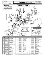
IPL, POULAN, PO175A42LT, 96048004800, 2012-11, TRACTOR
IPL, POULAN, PO175A42LT, 96048004800, 2012-11, TRACTOR
IPL, POULAN, PO175A42LT, 96048004800, 2012-11, TRACTOR

Create successful ePaper yourself
Turn your PDF publications into a flip-book with our unique Google optimized e-Paper software.
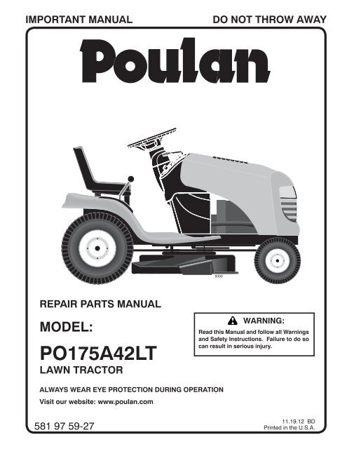
IMPORTANT MANUAL<br />
DO NOT THROW AWAY<br />
5000<br />
REPAIR PARTS MANUAL<br />
MODEL:<br />
<strong>PO175A42LT</strong><br />
LAWN <strong>TRACTOR</strong><br />
WARNING:<br />
Read this Man u al and follow all Warnings<br />
and Safety Instructions. Fail ure to do so<br />
can re sult in serious in ju ry.<br />
ALWAYS WEAR EYE PROTECTION DURING OPERATION<br />
Visit our website: www.poulan.com<br />
<strong>11</strong>.19.12 BD<br />
581 97 59-27 Printed in the U.S.A.
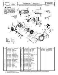
<strong>TRACTOR</strong> - MODEL NO. <strong>PO175A42LT</strong> (<strong>96048004800</strong>), PRODUCT NO. 960 48 00-48<br />
SCHEMATIC<br />
SCH<strong>11</strong><br />
RED<br />
A<br />
AMMETER<br />
(OPTIONAL)<br />
FUSE<br />
BATTERY<br />
RED<br />
SOLENOID<br />
BLACK<br />
STARTER<br />
M<br />
WHITE<br />
WHITE<br />
B<br />
S<br />
M<br />
G<br />
L<br />
A1<br />
A2<br />
ATTACHMENT CLUTCH<br />
(CLUTCH OFF)<br />
BLACK<br />
CLUTCH/BRAKE<br />
(PEDAL UP)<br />
GRAY<br />
BLACK<br />
REVERSE SWITCH<br />
(NOT IN REVERSE)<br />
BLACK<br />
BLACK<br />
BLACK<br />
BLACK<br />
2<br />
3<br />
1<br />
BLACK<br />
BLACK<br />
BLACK<br />
SEAT SWITCH<br />
(NOT OCCUPIED)<br />
6<br />
GRAY<br />
NOTE<br />
YOUR <strong>TRACTOR</strong> IS<br />
EQUIPPED WITH A SPECIAL<br />
ALTERNATOR SYSTEM.<br />
THE LIGHTS ARE NOT<br />
CONNECTED TO THE<br />
BATTERY, BUT HAVE THEIR<br />
OWN ELECTRICAL SOURCE.<br />
BECAUSE OF THIS, THE<br />
BRIGHTNESS OF THE LIGHTS<br />
WILL CHANGE WITH ENGINE<br />
SPEED. AT IDLE THE LIGHTS<br />
WILL DIM. AS THE ENGINE IS<br />
SPEEDED UP, THE LIGHTS<br />
WILL BECOME THEIR<br />
BRIGHTEST.<br />
BLACK<br />
BLACK /WHITE<br />
BLUE<br />
BLUE<br />
FUEL<br />
LINE<br />
FUEL SHUT-OFF<br />
SOLENOID<br />
(IF SO EQUIPPED)<br />
RED<br />
LIGHT SWITCH<br />
IGNITION<br />
UNIT<br />
(OPTIONAL)<br />
HOUR<br />
METER<br />
ORANGE<br />
JUNCTION<br />
CONNECTOR<br />
CHASSIS<br />
HARNESS<br />
CHARGING SYSTEM OUTPUT<br />
3 AMP DC @ 3600 RPM<br />
SPARK<br />
PLUGS GAP<br />
(2 PLUGS ON<br />
TWIN CYL. ENGINES)<br />
BLACK<br />
12V<br />
POWER OUTLET<br />
(OPTIONAL)<br />
SHORTING<br />
CONNECTOR<br />
LIGHTING SYSTEM OUTPUT<br />
5 AMP AC @ 3600 RPM ALTERNATOR<br />
DIODE<br />
28 VOLTS AC MIN. @ 3600 RPM<br />
(CHARGING SYSTEM DISCONNECTED)<br />
14 VOLTS AC MIN. @ 3600 RPM (LIGHTS OFF)<br />
BROWN<br />
BLACK<br />
IGNITION SWITCH<br />
HEADLIGHTS<br />
POSITION CIRCUIT<br />
OFF<br />
RUN/OVERRIDE<br />
M+G+A1<br />
B+A1<br />
RUN B+A1<br />
START B+S+A1<br />
“MAKE”<br />
L+A2<br />
3<br />
2<br />
1<br />
CHASSIS HARNESS<br />
CONNECTOR<br />
(MATING SIDE)<br />
6<br />
5<br />
4<br />
6 3<br />
5 2<br />
4<br />
1<br />
DASH HARNESS<br />
CONNECTOR<br />
(MATING SIDE)<br />
WIRING INSULATED CLIPS<br />
NOTE: IF WIRING INSULATED<br />
CLIPS WERE REMOVED FOR<br />
SERVICING OF UNIT, THEY<br />
SHOULD BE RE-INSTALLED TO<br />
PROPERLY SECURE YOUR<br />
WIRING.<br />
NON-REMOVABLE<br />
CONNECTIONS<br />
REMOVABLE<br />
CONNECTIONS<br />
3
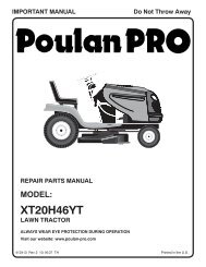
<strong>TRACTOR</strong> - MODEL NO. <strong>PO175A42LT</strong> (<strong>96048004800</strong>), PRODUCT NO. 960 48 00-48<br />
ELECTRICAL<br />
T06K<br />
With 12V Outlet Option<br />
103<br />
79<br />
22<br />
21<br />
30<br />
33<br />
87<br />
59<br />
With Service Minder Option<br />
34<br />
43<br />
27<br />
42<br />
46<br />
26<br />
40<br />
41<br />
25<br />
16<br />
90<br />
71<br />
2<br />
102<br />
29<br />
28 55<br />
105<br />
4
<strong>TRACTOR</strong> - MODEL NO. <strong>PO175A42LT</strong> (<strong>96048004800</strong>), PRODUCT NO. 960 48 00-48<br />
ELECTRICAL<br />
KEY PART<br />
NO. NO. DESCRIPTION<br />
1 532 16 34-65 Battery<br />
2 874 76 04-12 Bolt Hex Head 1/4-20 x 3/4<br />
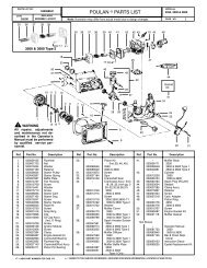
8 532 19 32-28 Box Battery<br />
16 532 17 61-38 Switch Interlock Push-In<br />
21 532 17 56-88 Harness Socket Light w/4152J<br />
22 532 00 41-52 Bulb Light<br />
25 532 41 28-94 Cable Starter<br />
26 532 17 51-58 Fuse<br />
27 873 51 04-00 Nut Keps Hex 1/4-20 unc<br />
28 532 19 88-85 Cable, Ground<br />
29 532 19 27-49 Switch, Seat<br />
30 532 19 33-50 Switch, Ign<br />
33 532 41 19-34 Key/Chain<br />
34 532 <strong>11</strong> 07-12 Switch Light/Reset<br />
40 532 40 10-98 Harness Ign. Dash<br />
41 817 72 04-08 Screw Thd Cut 1/4-20 x 1/2<br />
42 532 13 15-63 Cover, Terminal<br />
43 532 19 25-07 Solenoid<br />
55 817 06 05-12 Screw Thdrol 5/16-18 x 3/4 TYTT<br />
71 532 44 15-44 Harness Ign. Chassis<br />
79 532 17 52-42 Socket Asm. Bulb<br />
87 532 19 78-02 Switch Interlock<br />
90 532 43 53-95 Cover Terminal<br />
102 581 90 16-01 Harness Pigtail<br />
105 532 40 75-68 Switch Reverse<br />
NOTE: All component dimensions given in U.S. inches<br />
1 inch = 25.4 mm<br />
5
<strong>TRACTOR</strong> - MODEL NO. <strong>PO175A42LT</strong> (<strong>96048004800</strong>), PRODUCT NO. 960 48 00-48<br />
CHASSIS<br />
302<br />
153<br />
14<br />
18<br />
151<br />
176<br />
5<br />
137<br />
130<br />
176<br />
182<br />
176<br />
177<br />
175<br />
68<br />
235<br />
236<br />
68<br />
34<br />
235<br />
36<br />
176<br />
181<br />
196<br />
37<br />
194<br />
194<br />
183<br />
68<br />
183<br />
236<br />
68<br />
213<br />
138<br />
68<br />
218<br />
180<br />
68<br />
287<br />
162<br />
181<br />
189<br />
58<br />
228<br />
189<br />
217<br />
194<br />
52<br />
159<br />
189<br />
228<br />
189<br />
152<br />
189<br />
Chassis-tex_ALPHA_5<br />
159<br />
6
<strong>TRACTOR</strong> - MODEL NO. <strong>PO175A42LT</strong> (<strong>96048004800</strong>), PRODUCT NO. 960 48 00-48<br />
CHASSIS<br />
KEY PART<br />
NO. NO. DESCRIPTION<br />
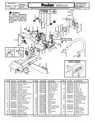
5 581 41 17-64 Dash<br />
14 532 40 61-79 Hood<br />
18 532 42 67-41 Grille<br />
34 580 91 08-01 Plate Engine<br />
36 817 06 05-12 Screw 5/16-18 x 3/4<br />
37 532 42 09-86 Fender<br />
52 873 68 05-00 Nut Lock 5/16-18<br />
58 532 41 22-80 Drawbar Upper<br />
68 817 49 05-08 Screw Thdrol 5/16-18 x 1/2<br />
130 532 41 63-58 Screw #10 x 0.750<br />
137 532 18 49-21 Bumper Dash<br />
138 532 40 97-30 Cupholder<br />
151 532 18 75-68 Bracket Pivot<br />
152 532 19 95-35 Shield Browning<br />
153 532 19 54-02 Lens Bar<br />
159 817 00 06-12 Screw Hexwsh Thrd 3/8-16 x 3/4<br />
162 532 14 24-32 Screw<br />
175 532 19 32-43 Crossmember<br />
176 532 40 07-76 Screw 10-24 x 5/8<br />
177 532 19 52-28 Bushing Steering<br />
180 532 41 50-63 Chassis<br />
181 532 40 30-04 Bushing<br />
182 532 19 30-57 Dash Lower<br />
183 874 52 05-20 Bolt 5/16-18 x 1-1/4<br />
189 817 00 05-12 Screw 5/16-18 x 3/4<br />
194 873 90 05-00 Nut Lock Hex Flange 5/16-18<br />
196 532 41 45-79 Console Asm. Deck Lift<br />
213 874 76 05-12 Bolt 5/16-18 x 3/4<br />
217 532 40 91-67 Rod Pivot<br />
218 532 19 63-95 X-Piece Hood Stop<br />
228 532 19 51-61 Stud Fastner<br />
235 532 40 61-29 Spacer Fender<br />
236 873 93 05-00 Nut Lock 5/16-18 unc<br />
287 817 60 04-06 Screw 1/4-20 x 3/8<br />
302 532 18 75-69 Insert Reflective<br />
NOTE: All component dimensions given in U.S. inches<br />
1 inch = 25.4 mm<br />
7
<strong>TRACTOR</strong> - MODEL NO. <strong>PO175A42LT</strong> (<strong>96048004800</strong>), PRODUCT NO. 960 48 00-48<br />
DRIVE<br />
70<br />
185<br />
74<br />
143<br />
367<br />
56<br />
51<br />
184<br />
221<br />
195<br />
6<br />
42<br />
64<br />
35<br />
160<br />
203<br />
167<br />
160<br />
161<br />
299<br />
5<br />
303<br />
190<br />
49<br />
186<br />
189<br />
187<br />
50<br />
51<br />
188<br />
165<br />
67<br />
159<br />
15 159<br />
29<br />
125<br />
17<br />
374 125<br />
172<br />
369<br />
300<br />
373<br />
302<br />
375<br />
166<br />
301<br />
51<br />
52<br />
51<br />
176<br />
178<br />
175<br />
174<br />
297<br />
233<br />
232<br />
<strong>11</strong>6<br />
125<br />
22<br />
23<br />
125<br />
166<br />
1<br />
<strong>11</strong>6<br />
73<br />
2<br />
205<br />
99<br />
37<br />
33<br />
73<br />
296 296<br />
drive-tex_VATR_<strong>11</strong><br />
8
<strong>TRACTOR</strong> - MODEL NO. <strong>PO175A42LT</strong> (<strong>96048004800</strong>), PRODUCT NO. 960 48 00-48<br />
DRIVE<br />
KEY PART<br />
NO.<br />
1<br />
NO.<br />
– – – – – –<br />
DESCRIPTION<br />
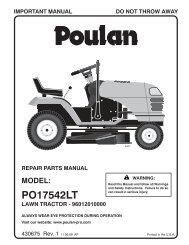
Transmission, Gentrans<br />
(580486301) (Order parts from<br />
transaxle manufacturer.)<br />
2 532 12 35-83 Key.Square .2.0 x .1845/.1865<br />
5 873 68 06-00 Nut 3/8-16<br />
6 532 12 40-28 Bushing Snap<br />
15 819 13 13-16 Washer 13/32 x 13/16 x 1 Gr. 5<br />
17 532 41 36-78 Spring Brake<br />
22 532 42 10-63 Rod Shift<br />
23 532 10 69-33 Knob<br />
29 581 47 93-01 Brake Rod<br />
33 812 00 00-01 E-Ring. #5133-75<br />
35 532 19 77-22 Rod.Brake.Parking. Lt.Tex<br />
37 532 18 89-67 Washer Harden .793 x 1.637 x 060<br />
42 532 12 48-72 Cover.Pedal.Blk.Round<br />
49 872 <strong>11</strong> 06-14 Bolt.Rdhd.3/8-16 unc x1-3/4.Gr 5<br />
50 532 19 43-27 Idler.Flat<br />
51 873 90 06-00 Nut, Hex, Flangelock 3/8-16<br />
52 532 19 43-26 Idler.V-Groove<br />
56 532 19 72-53 Belt.Drive.100.97"<br />
64 580 40 15-01 Shaft Asm.Pedal.Brake Control<br />
67 819 13 13-12 Washer 13/32 x 13/16 x 12 Ga.<br />
70 532 44 03-23 Console<br />
73 874 49 05-44 Bolt.Hex.Flghd.5/16-18.Gr.5<br />
74 532 14 24-32 Screw.Hex.Wsh.Hi-Lo.1/4 x 1/2<br />
unc<br />
99 532 43 59-35 Rod Bypass<br />
<strong>11</strong>6 873 90 05-00 Nut Lock Hex Flange 5/16-18 unc<br />
125 817 00 05-12 Screw.5/16-18 x 3/4.Smgml.Tap/Bl<br />
143 817 49 05-08 Screw.Thdrol.5/16-18 x 1/2 Tytt<br />
159 876 02 04-12 Pin Cotter<br />
160 532 16 94-84 Retainer.Clip(M).Dia.290<br />
161 532 10 57-09 Spring.Return.Clutch.6.75<br />
165 532 19 62-12 Bushing.Shaft.Brake.Hand Contr<br />
166 532 42 91-64 Nut Push .625<br />
KEY PART<br />
NO.<br />
167<br />
NO.<br />
532 40 52-57<br />
DESCRIPTION<br />
Latch.Brake.Parking<br />
172 532 41 56-64 Strap Torque Lh/Rh<br />
174 532 19 72-89 Nut.Push..500<br />
175 532 41 56-77 Shaft Asm Shift<br />
176 532 19 62-14 Arm.Clevis.Rod.Shift<br />
178 532 19 74-56 Spring.Shift.Gt.2006<br />
184 532 44 15-04 Handle.Parking Brake.Lttex.505<br />
185 872 <strong>11</strong> 06-22 Bolt.Rdhd.3/8-16 unc x 2-3/4 Gr5<br />
186 532 19 43-21 Spacer.Retainer<br />
187 819 13 32-10 Washer.13/32 x 2 x 10 Ga.<br />
188 532 19 43-23 Link.Clutch.Ground Drive<br />
189 532 19 43-17 Bellcrank.Groundrive.Nstg/Nstl<br />
190 532 19 43-18 Keeper.Bellcrank.Drive.Ground<br />
195 581 50 46-01 Bracket Brake<br />
203 819 <strong>11</strong> <strong>11</strong>-16 Washer <strong>11</strong>/32 x <strong>11</strong>/16 x 16 Ga.<br />
205 532 12 17-48 Washer.25/32 x 1-5/8 x 16Ga.<br />
221 532 40 31-87 Retainer.Spring.Clip.Handle<br />
232 874 78 07-16 Bolt.Fin Hex.7/16-14 x 1 Gr5<br />
233 532 40 52-96 Washer.Serrated<br />
296 532 42 04-71 Screw Thdrol 5/16-18 x 3<br />
297 532 42 02-23 Nut Push 1/4<br />
299 532 41 56-83 Bracket Mount Idler<br />
300 532 41 56-81 Keeper Idler Rear<br />
301 532 41 56-80 Pulley Idler V-Groove<br />
302 581 42 05-01 Pulley Idler Flat 2.0 Od<br />
303 872 <strong>11</strong> 06-18 Bolt Rdhd Sgnk 3/8-16 x 2-1/4<br />
367 872 <strong>11</strong> 06-08 Bolt 3/8-16 x 1 Gr. 5<br />
369 581 57 74-01 Clip E Variator<br />
373 581 46 18-01 Spacer Idler<br />
374 581 47 52-01 Arm Control Brake<br />
375 874 76 06-36 Bolt 3/8-16 x 2-1/4<br />
NOTE: All component dimensions given in U.S. inches<br />
1 inch = 25.4 mm<br />
9
<strong>TRACTOR</strong> - MODEL NO. <strong>PO175A42LT</strong> (<strong>96048004800</strong>), PRODUCT NO. 960 48 00-48<br />
ENGINE<br />
1<br />
21<br />
20<br />
45<br />
84<br />
122<br />
79<br />
18<br />
97<br />
15<br />
96<br />
12<br />
69<br />
2<br />
37<br />
28<br />
42<br />
29<br />
90<br />
85<br />
9<br />
OPTIONAL EQUIPMENT<br />
Spark Arrester<br />
engine-tex_BS_76<br />
10
<strong>TRACTOR</strong> - MODEL NO. <strong>PO175A42LT</strong> (<strong>96048004800</strong>), PRODUCT NO. 960 48 00-48<br />
ENGINE<br />
KEY PART<br />
NO. NO. DESCRIPTION<br />
1 – – – – – – Engine B&S Model No. 31C707-<br />
3487-G5 (438654) (Order parts from<br />
engine manufacturer.)<br />
2 532 13 73-52 Muffler<br />
9 532 19 43-19 Keeper Belt Engine<br />
12 532 40 19-85 Pulley Engine<br />
15 581 28 99-01 Tank Fuel<br />
18 532 43 02-20 Cap Asm<br />
20 532 17 05-45 Control Throttle<br />
21 532 41 63-58 Screw # 10 x 0.750<br />
28 532 40 <strong>11</strong>-37 Fuel Line<br />
29 532 13 71-80 Spark Arrester Kit<br />
37 532 12 34-87 Clamp Hose<br />
42 810 04 07-00 Washer Lock 7/16<br />
45 873 51 04-00 Nut Keps Hex 1/4-20 unc<br />
69 532 16 52-91 Gasket<br />
79 532 19 23-34 Screw Socket Hd. 5/16-18 x .75<br />
84 817 06 06-20 Screw 3/8-16 x 1-1/4<br />
85 532 17 39-37 Bolt Hex 7/16-20 x 4 x Gr. 5-1.5 Thr<br />
90 817 00 06-16 Screw 3/8-16 x 1<br />
96 819 09 14-16 Washer 9/32 x 7/8 x 16 Ga.<br />
97 817 67 04-12 Screw 1/4-20 x 3/4<br />
122 532 42 19-22 Extension Oil Drain<br />
NOTE: All component dimensions given in U.S. inches<br />
1 inch = 25.4 mm<br />
For engine service and replacement parts, call the toll free<br />
number for your engine manufacturer listed below:<br />
Briggs & Stratton 1-800-233-3723<br />
Engine Power Rating Information<br />
The gross power rating for individual gas engine models is labeled in accordance with SAE (Society of Automotive Engineers)<br />
code J1940 (Small Engine Power & Torque Rating Procedure), and rating performance has been obtained and<br />
corrected in accordance with SAE J1995 (Revision 2002-05). Torque values are derived at 3060 RPM; horsepower values<br />
are derived at 3600 RPM. Actual gross engine power will be lower and is affected by, among other things, ambient operating<br />
conditions and engine-to-engine variability. Given both the wide array of products on which engines are placed and<br />
the variety of environmental issues applicable to operating the equipment, the gas engine will not develop the rated gross<br />
power when used in a given piece of power equipment (actual “on-site” or net power). This difference is due to a variety<br />
of factors including, but not limited to, accessories (air cleaner, exhaust, charging, cooling, carburetor, fuel pump, etc.),<br />
application limitations, ambient operating conditions (temperature, humidity, altitude), and engine-to-engine variability.<br />
Due to manufacturing and capacity limitations, Briggs & Stratton may substitute an engine of higher rated power for this<br />
Series engine.<br />
<strong>11</strong>
<strong>TRACTOR</strong> - MODEL NO. <strong>PO175A42LT</strong> (<strong>96048004800</strong>), PRODUCT NO. 960 48 00-48<br />
STEERING ASSEMBLY<br />
26<br />
72<br />
33<br />
45<br />
1<br />
20<br />
21<br />
71<br />
16<br />
13<br />
28<br />
64<br />
63<br />
57<br />
28<br />
60<br />
22<br />
57<br />
63<br />
9<br />
8<br />
7<br />
66<br />
19<br />
122<br />
35<br />
59<br />
6<br />
122<br />
74<br />
74<br />
2<br />
67<br />
9<br />
8<br />
74<br />
7<br />
58<br />
67<br />
74<br />
61<br />
4<br />
69<br />
14<br />
15<br />
62<br />
14<br />
6<br />
5<br />
13<br />
8<br />
68<br />
70<br />
15<br />
13<br />
steering-tex_STDHRS_14<br />
53<br />
12
<strong>TRACTOR</strong> - MODEL NO. <strong>PO175A42LT</strong> (<strong>96048004800</strong>), PRODUCT NO. 960 48 00-48<br />
STEERING ASSEMBLY<br />
KEY PART<br />
NO. NO. DESCRIPTION<br />
1 532 42 45-43 Wheel, Steering<br />
2 532 41 81-68 Axle<br />
4 532 40 30-87 Spindle Asm., LH<br />
5 532 40 30-88 Spindle Asm., RH<br />
6 532 12 49-31 Washer, Thrust<br />
7 532 12 17-48 Washer 25/32 x 1-5/8 x 16 Ga.<br />
8 812 00 00-29 Ring, Klip #T5304-75<br />
9 532 12 12-32 Cap, Spindle<br />
13 532 12 17-49 Washer 25/32 x 1-1/4 x 16 Ga.<br />
14 810 04 06-00 Washer, Lock Hvy Hlcl Spr 3/8<br />
15 873 54 06-00 Nut, Crown Lock 3/8-24 unf<br />
16 532 42 93-74 Shaft Steering<br />
19 532 19 47-29 Plate Steering<br />
20 532 41 12-91 Boot Steering<br />
21 532 18 67-37 Adapter, Wheel Steering<br />
22 532 42 05-37 Steering Support<br />
26 532 42 46-94 Insert, Wheel Steering<br />
28 817 00 06-12 Screw 3/8-16 x 3/4<br />
33 810 04 05-00 Washer Lock 5/16<br />
35 532 19 47-32 Gear, Sector Plate<br />
45 819 <strong>11</strong> 38-12 Washer <strong>11</strong>/32 x 2-38 x 12 Ga.<br />
53 532 18 89-67 Washer Hardened .793 x 1.637 x .060<br />
57 532 40 74-65 Bracket Upstop<br />
58 532 19 47-47 Bolt Shoulder Sector Pivot CFM<br />
59 532 19 47-48 Washer Thrust Sector Steering<br />
60 873 97 10-00 Nut Flange Lock 5/8-<strong>11</strong><br />
61 532 19 47-40 Draglink, LH<br />
62 532 19 47-41 Draglink, RH<br />
63 817 00 05-12 Screw 5/16-18 x 3/4<br />
64 532 19 98-49 Retainer Clip Spring Steering<br />
66 871 02 07-48 Bolt Hex Fghd 7/16-14 x 3 Serr<br />
67 532 19 47-37 Bushing PM Front Axle<br />
68 873 90 07-00 Nut Lock Flange 7/16-14 Gr. 5<br />
69 532 19 91-62 Washer 1.5 x .505 x .<strong>11</strong>8<br />
70 532 19 61-97 Bracket Deck Susp. Front<br />
71 532 19 07-52 Shaft Extension Steering<br />
72 532 42 89-82 Bolt 5/16-18 x 4 w/Patch<br />
74 532 12 49-37 Bearing<br />
122 532 44 49-62 Cap Gear<br />
NOTE: All component dimensions given in U.S. inches<br />
1 inch = 25.4 mm<br />
13
<strong>TRACTOR</strong> - MODEL NO. <strong>PO175A42LT</strong> (<strong>96048004800</strong>), PRODUCT NO. 960 48 00-48<br />
MOWER DECK<br />
70<br />
67<br />
152<br />
7<br />
37<br />
7<br />
<strong>11</strong>6<br />
<strong>11</strong>7 <strong>11</strong>9<br />
30<br />
40<br />
57<br />
43<br />
42<br />
56<br />
<strong>11</strong>3<br />
40<br />
145<br />
59<br />
60<br />
57<br />
56<br />
64<br />
40<br />
36<br />
55<br />
46<br />
63<br />
147<br />
30<br />
38<br />
68<br />
195<br />
122<br />
123<br />
195<br />
38<br />
47<br />
192<br />
144<br />
241<br />
242<br />
34<br />
33<br />
32<br />
31<br />
1<br />
30<br />
21<br />
40 <strong>11</strong>9<br />
<strong>11</strong>7<br />
<strong>11</strong>6<br />
62<br />
21<br />
188<br />
189<br />
69<br />
21<br />
23<br />
24<br />
25<br />
19<br />
6<br />
<strong>11</strong>3<br />
189<br />
26<br />
6<br />
188<br />
15<br />
29<br />
19<br />
14<br />
20<br />
13<br />
69<br />
69<br />
27<br />
<strong>11</strong><br />
42_D_man-tex_LT_45<br />
8<br />
14
<strong>TRACTOR</strong> - MODEL NO. <strong>PO175A42LT</strong> (<strong>96048004800</strong>), PRODUCT NO. 960 48 00-48<br />
MOWER DECK<br />
KEY PART<br />
NO. NO. DESCRIPTION<br />
1 532 19 64-95 Mower Housing<br />
6 532 19 51-86 Arm Suspension<br />
7 532 41 63-58 Screw #10 x 0.750 BOS Thread<br />
8 532 19 30-03 Bolt/Washer Asm 7/16-20 unf<br />
<strong>11</strong> 532 13 89-71 Blade, 42" Hi-Lift<br />
(For bagging or discharge)<br />
13 532 19 28-72 Shaft Assembly, Mandrel<br />
14 532 18 72-81 Housing, Mandrel<br />
15 532 <strong>11</strong> 04-85 Bearing, Ball, Mandrel<br />
19 532 19 65-39 Bolt, Shoulder<br />
20 532 15 97-70 Baffle, Vortex<br />
21 873 68 05-00 Nut, Crownlock 5/16-18 unc<br />
23 532 19 25-57 Bracket, Deflector<br />
24 532 10 53-04 Cap, Sleeve<br />
25 532 19 70-26 Spring, Torsion, Deflector<br />
26 532 <strong>11</strong> 04-52 Nut, Push<br />
27 532 40 30-04 Shield, Deflector<br />
29 532 13 14-91 Rod, Hinge<br />
30 532 17 39-84 Screw Thdrol Rolling Wsh Hd<br />
31 532 18 76-90 Washer, Spacer<br />
32 532 19 74-73 Pulley, Mandrel<br />
33 532 40 02-34 Nut, Toplock, Flanged<br />
34 872 <strong>11</strong> 06-12 Bolt Carr Sh. 3/8-16 x 1-1/2 Gr. 5<br />
36 532 19 73-79 Pulley, Idler 4.50 RAW<br />
37 819 13 13-16 Washer 13/32 x 13/16 x 16 Ga.<br />
38 532 43 25-20 Keeper Belt Mandrel<br />
40 873 90 06-00 Nut, Lock Flg. 3/8-16 unc<br />
42 532 19 84-10 Spring Torsion Brake<br />
43 532 19 72-56 Spring Torsion Retainer<br />
46 532 13 77-29 Screw Thd Roll 1/4-20 x 5/8<br />
47 532 19 72-50 Bracket Clutch Cable<br />
55 532 43 71-10 Arm, Idler<br />
56 532 19 90-92 Spacer, Retainer<br />
57 817 00 06-16 Screw Hexwsh Thd 3/8-16 x 1<br />
59 532 14 10-43 Guard, Tuv Idler (94)<br />
60 532 19 72-61 Arm Brake Mower<br />
KEY PART<br />
NO. NO. DESCRIPTION<br />
62 872 <strong>11</strong> 06-16 Bolt Rdhd Sqnk 3/8-16 unc x 2<br />
63 532 19 94-77 Arm Brake Mower<br />
64 532 19 97-90 Linkage Brake<br />
67 532 40 30-12 Handle, Clutch Cable<br />
68 532 42 96-36 V-Belt<br />
69 872 14 05-05 Bolt Rdhd Sqnk 5/16-18 x 5/8<br />
70 532 19 83-32 Clutch Asm. Manual<br />
<strong>11</strong>3 817 00 05-10 Screw 5/16-18<br />
<strong>11</strong>6 532 12 48-42 Bolt Shoulder<br />
<strong>11</strong>7 532 18 86-06 Wheel Gage<br />
<strong>11</strong>9 819 12 14-14 Washer 3/8 x 7/8 x 14 Ga.<br />
122 532 19 72-58 Keeper Belt Eng. LH<br />
123 532 19 72-59 Keeper Belt Eng. RH<br />
144 532 19 92-04 Keeper Belt<br />
145 532 19 31-97 Pulley Idler Primary<br />
147 532 40 19-71 Spring Return<br />
152 532 43 51-<strong>11</strong> Cable Clutch Manual w/Spr.<br />
188 532 19 51-61 Stud Fastener<br />
189 873 90 05-00 Nut Lock Hex Flange<br />
192 532 19 72-60 Bracket Brake Stand LH<br />
195 817 00 06-12 Screw Hexwsh Thdr 3/8-16 x 3/4<br />
241 532 15 29-27 Screw #10-32.5. 3/8 Flange<br />
242 532 41 55-98 Port Washout<br />
- - 532 19 28-70 Mandrel Assembly (Includes housing<br />
(key #14), shaft assembly (key<br />
#13), and bearing (key #15) and nut<br />
(key #33) only - pulley/washer and<br />
blade bolt/washers not included)<br />
- - 532 43 77-30 Replacement Mower, Complete<br />
NOTE: All component dimensions given in U.S. inches<br />
1 inch = 25.4 mm<br />
15
<strong>TRACTOR</strong> - MODEL NO. <strong>PO175A42LT</strong> (<strong>96048004800</strong>), PRODUCT NO. 960 48 00-48<br />
MOWER LIFT<br />
7<br />
87<br />
90 98<br />
10<br />
89<br />
3<br />
97<br />
100<br />
2<br />
91<br />
88<br />
97<br />
87<br />
89<br />
101*<br />
89<br />
87<br />
lift-tex_17_r3 *Key 91 may be substituted for Key 101<br />
KEY PART<br />
NO. NO. DESCRIPTION<br />
2 532 42 20-27 Shaft Asm., Lift<br />
3 532 19 52-31 Lever Asm., Lift RH<br />
7 580 96 23-01 Grip, Lever<br />
10 532 19 63-14 Spring Torsion<br />
87 532 19 42-09 Pin Cotter 7/16 Bow Tie Lock<br />
88 532 41 07-10 Spring Lift Assist<br />
89 819 19 19-12 Washer Clear Zinc<br />
90 532 19 42-08 Pin Cotter 5/16 Bow Tie Lock<br />
91 532 19 51-81 Link Lift Susp Mower Rear<br />
KEY PART<br />
NO. NO. DESCRIPTION<br />
97 817 00 06-12 Screw 3/8-16 x .75 Smgml<br />
Tap/R.Z<br />
98 532 19 52-70 Link Lift Susp. Front Mower<br />
100 873 93 06-00 Nut Center Lock 3/8-16 unc<br />
101 532 40 70-03 Link Asm Lift Fixed<br />
NOTE: All component dimensions given in U.S. inches<br />
1 inch = 25.4 mm<br />
16
<strong>TRACTOR</strong> - MODEL NO. <strong>PO175A42LT</strong> (<strong>96048004800</strong>), PRODUCT NO. 960 48 00-48<br />
SEAT ASSEMBLY<br />
1<br />
8<br />
7<br />
8<br />
8<br />
7<br />
8<br />
14<br />
10<br />
16<br />
15<br />
42<br />
12<br />
19<br />
21<br />
6<br />
6<br />
37<br />
5<br />
37<br />
21<br />
13<br />
17<br />
2<br />
3<br />
seat-tex_knob_1<br />
KEY PART<br />
NO. NO. DESCRIPTION<br />
1 532 40 30-17 Seat<br />
2 532 18 01-66 Bracket Pivot Fender<br />
3 532 14 06-75 Strap, Asm Fender<br />
5 532 14 50-06 Clip Push-In Hinged<br />
6 873 80 06-00 Nut, Lock w/Ins. 3/8-16 unc<br />
7 532 12 41-81 Spring, Seat Cprsn<br />
8 532 17 18-77 Bolt 5/16-18 unc x 3/4 w/Sems<br />
10 532 44 18-05 Pan, Seat<br />
12 532 19 93-70 Bracket Mounting Seat<br />
13 532 12 12-48 Bushing Snap<br />
14 872 05 04-12 Bolt 1/4-20 x 1-1/2<br />
KEY PART<br />
NO. NO. DESCRIPTION<br />
15 532 13 43-00 Spacer Split<br />
16 532 12 37-40 Spring<br />
17 532 12 39-76 Nut Lock 1/4<br />
19 532 19 93-72 Knob Seat<br />
21 532 17 18-52 Bolt, Shoulder 5/16-18<br />
37 873 80 05-00 Nut, Lock 5/16-18 unc<br />
42 532 19 93-71 Washer<br />
NOTE: All component dimensions given in U.S. inches<br />
1 inch = 25.4 mm<br />
17
<strong>TRACTOR</strong> - MODEL NO. <strong>PO175A42LT</strong> (<strong>96048004800</strong>), PRODUCT NO. 960 48 00-48<br />
DECALS<br />
10<br />
13<br />
2<br />
6<br />
2<br />
9<br />
1<br />
3<br />
3<br />
5 4<br />
5<br />
8<br />
7<br />
12<br />
KEY PART<br />
NO.<br />
1<br />
NO. DESCRIPTION<br />
581 57 90-01 Decal, Fender Warning<br />
2 532 43 19 83 Decal, Hood<br />
3 532 44 68-01 Decal, Fender<br />
4 581 57 95-01 Decal, Mower<br />
5 532 43 20-72 Decal, Lower Dash<br />
6 532 44 66-06 Decal, Replacement<br />
7 581 57 99-01 Decal, Warning Spark.<br />
8 532 43 10-92 Decal, Engine HP<br />
9 532 14 50-05 Decal, Battery Dnge/Poi<br />
KEY PART<br />
NO.<br />
10<br />
NO. DESCRIPTION<br />
532 43 19-86 Decal, Fender<br />
12 581 58 00-01 Decal, Mower V-Belt Schematic<br />
13 532 43 19-82 Decal, Wheel Steering<br />
- - 581 72 48-01 Decal, Bypass<br />
- - 532 40 95-05 Pad, Footrest, LH<br />
- - 532 41 12-73 Pad, Footrest, RH<br />
- - 581 97 59-32 Manual, Operator's<br />
(English/French)<br />
- - 581 97 59-27 Manual, Parts (English/French)<br />
WHEELS AND TIRES<br />
1<br />
2<br />
<strong>11</strong> 3<br />
7<br />
6<br />
4<br />
10<br />
5<br />
9<br />
8<br />
KEY PART<br />
NO.<br />
1<br />
NO. DESCRIPTION<br />
532 05 91-92 Cap Valve Tire<br />
2 532 06 51-39 Stem Valve<br />
3 532 18 33-37 Rim Front<br />
4 532 05 99-04 Tube Front (Service Item Only)<br />
5 532 10 62-22 Tire Front 15 x 6.0-6<br />
6 532 12 49-57 Fitting Grease (Front Wheel Only)<br />
7 532 12 49-59 Bearing Flange (Front Wheel Only)<br />
8 532 17 50-39 Cap Axle Blk 1 50 x 1 00<br />
9 532 42 05-31 Tire R 18 x 9.5-8<br />
10 532 12 49-26 Tube Rear (Service Item Only)<br />
<strong>11</strong> 532 13 83-38 Rim Asm 8" Rear<br />
- - 532 14 43-34 Sealant, Tire (10 oz. Tube)<br />
NOTE: All component dimensions given in U.S. inches<br />
1 inch = 25.4 mm<br />
wheel_art_1-tex<br />
18
LIMITED WARRANTY<br />
The Manufacturer warrants to the original consumer purchaser that this product as manufactured is free from defects in materials<br />
and work man ship. For a period of two (2) years from date of purchase by the original consumer purchaser, we will repair<br />
or replace, at our option, without charge for parts or labor incurred in replacing parts, any part which we find to be defective<br />
due to materials or workmanship. This Warranty is subject to the following limitations and exclusions.<br />
1. This warranty does not apply to the engine, transaxle/transmission components, battery (except as noted below) or components<br />
parts thereof. Please refer to the applicable manufacturer's warranty on these items.<br />
2. Transportation charges for the movement of any power equipment unit or attachment are the responsibility of the pur chaser.<br />
Transportation charges for any parts submitted for replacement under this warranty must be paid by the purchaser unless<br />
such return is requested by the manufacturer.<br />
3. Battery Warranty: On products equipped with a Battery, we will replace, without charge to you, any battery which we find<br />
to be defective in manufacture, during the first ninety (90) days of ownership. After ninety (90) days, we will exchange the<br />
Battery, charging you 1/12 of the price of a new Battery for each full month from the date of the original sale. Battery must<br />
be maintained in accordance with the instructions furnished.<br />
4. The Warranty period for any products used for rental or commercial purposes is limited to 90 days from the date of original<br />
purchase.<br />
5. This Warranty applies only to products which have been properly assembled, adjusted, operated, and main tained in accor<br />
dance with the instructions furnished. This Warranty does not apply to any product which has been subjected to alteration,<br />
misuse, abuse, improper assembly or installation, delivery damage, or to normal wear of the product.<br />
6. Exclusions: Excluded from this Warranty are belts, blades, blade adapters, normal wear, normal adjustments, stan dard<br />
hardware and normal maintenance.<br />
7. In the event you have a claim under this Warranty, you must return the product to an authorized service dealer.<br />
Should you have any unanswered questions concerning this Warranty, please contact:<br />
HOP<br />
Outdoor Products Customer Service Dept.<br />
9335 Harris Corners Parkway<br />
Charlotte, NC 28269 USA<br />
In Canada contact:<br />
HOP<br />
5855 Terry Fox Way<br />
Mississauga, Ontario<br />
L5V 3E4<br />
giving the model number, serial number and date of purchase of your product and the name and address of the authorized<br />
dealer from whom it was purchased.<br />
THIS WARRANTY DOES NOT APPLY TO INCIDENTAL OR CONSEQUENTIAL DAMAGES AND ANY IMPLIED WAR RAN-<br />
TIES ARE LIMITED TO THE SAME TIME PERIODS STATED HEREIN FOR OUR EXPRESSED WARRANTIES. Some areas<br />
do not allow the limitation of consequential damages or limitations of how long an implied Warranty may last, so the above<br />
limitations or exclusions may not apply to you. This Warranty gives you specific legal rights, and you may have other rights<br />
which vary from locale to locale.<br />
This is a limited Warranty within the meaning of that term as defined in the Magnuson-Moss Act of 1975.<br />
19
PARTS AND SERVICE<br />
This product has been expertly en gi neered and carefully manu fac tured to rigid quality stan dards. As with all mechanical<br />
products, some adjustments or part replacement may be necessary during the life of your unit.<br />
For Parts and service, contact our authorized distributor: call 1-800-849-1297<br />
• For replacement parts, have available the following information:<br />
a. Model Number/Manufacturer's I.D. Number<br />
b. Description of part.<br />
For Technical Assistance: call 1-800-829-5886<br />
For a Parts Manual, go to our website: www.poulan.com<br />
NOTE:<br />
HOP provides parts and service through its au thor ized dis tribu tors and dealers; there fore, all<br />
requests for parts and service should be directed to your local dealer(s). The phi loso phy of HOP<br />
is to con tinu ally improve all of its prod ucts. If the operating characteristics or the appearance<br />
of your product differs from those described in this Manual, please contact your local dealer<br />
for updated in for ma tion and as sis tance.<br />
20
MANUEL IMPORTANT<br />
NE JETEZ PAS<br />
5000<br />
MANUEL DE PARTIES DE RÉPARATION<br />
MODÈLE:<br />
<strong>PO175A42LT</strong><br />
TRACTEUR DE PELOUSE<br />
AVERTISSEMENT:<br />
Lisez soigneusement le Man uel suivez tous<br />
les Aver tis se ments et les In struc tions de<br />
Sécurité. Les bles sures sérieuses peuvent<br />
en résulter si vous ne lisez pas ces Avertis<br />
se ments et In struc tions de Sécurité.<br />
PORTEZ TOUJOURS DES LUNETTES DE SÉCURITÉ LORS DE L’UTILISATION.<br />
Visitez notre site web: www.poulan.com<br />
<strong>11</strong>.19.12 BD<br />
581 97 59-27 Impreso en los E.E.U.U.
COMMENT UTILISER CE MANUEL<br />
Ce manuel a été dessiné pour fournir le client avec les moyens d'identification des pièces de détachées<br />
du tracteur quand il/elle a besoin de commander les pièces de rechange. Les illustrations<br />
ne peuvent pas représenter exactement le modèle que vous avez acheté. N'utilisez pas ce manuel<br />
comme un guide dans le montage et/ou démontage de votre tracteur. La visserie montrée est plus<br />
grande pour faciliter l'identification.<br />
Chaque tracteur a un numéro de modèle particulier.<br />
Le numéro de modèle du produit se trouvera sur l'aile, dessous le siège.<br />
Lorsque vous commandez des pièces de rechange, donnez toujours les renseignements suivants:<br />
• Produit - "Tracteur"<br />
• NUMÉRO DU MODÈLE - “P0175A42LT (<strong>96048004800</strong>)”<br />
• Numéro de la Pièce<br />
• Description de la Pièce<br />
TABLE DE MATIERES<br />
SCHÉMA ...................................................................................................................... 3<br />
ELECTRIQUE ...........................................................................................................4-5<br />
CHÂSSIS/ENCEINTES .............................................................................................6-7<br />
ENTRAÎNEMENT ......................................................................................................8-9<br />
MOTEUR ...............................................................................................................10-<strong>11</strong><br />
ENSEMBLE DE LA DIRECTION ..........................................................................12-13<br />
CARTER DE TONDEUSE .....................................................................................14-15<br />
LEVAGE DE LA TONDEUSE .................................................................................... 16<br />
ENSEMBLE DU SIÉGE ............................................................................................ 17<br />
DECALCOMANIES .................................................................................................... 18<br />
GARANTIE ................................................................................................................. 19<br />
L’ENTRETIEN ET LES PIÈCES DE RE CHANGE ..................................................... 20
TRACTEUR - NO. DE MODÈLE P0175A42LT (<strong>96048004800</strong>), NO. DE PROD. 960 48 00-48<br />
SCHÉMA<br />
SCH<strong>11</strong>-F<br />
ROUGE<br />
A<br />
AMPÈREMÈTRE<br />
(FACULTATIF)<br />
BATTERIE<br />
FUSIBLE<br />
ROUGE<br />
SOLÉNOÏDE<br />
NOIR<br />
DÉMARREUR<br />
M<br />
BLANCHE<br />
BLANCHE<br />
S<br />
B M<br />
A1<br />
G<br />
L A2<br />
NOIR<br />
FREIN/<br />
EMBRAYAGE<br />
(PÉDALE HAUTE)<br />
EMBRAYAGE FREIN<br />
PÉDALE UP<br />
GRIS<br />
NOIR<br />
REVERS PERMUTE<br />
PAS DANS REVERS<br />
NOIR<br />
NOIR<br />
NOIR<br />
NOIR<br />
2<br />
3<br />
1<br />
NOIR<br />
NOIR<br />
NOIR<br />
INTERRUPTEUR DU SIÈGE<br />
(NON OCCUPÉ)<br />
6<br />
GRIS<br />
JONCTION<br />
CONNECTEUR<br />
REMARQUE<br />
VOTRE TRACTEUR EST ÉQUIPÉ<br />
D'UN SYSTÈME D'ALTERNATEUR<br />
SPÉCIAL AU LIEU D'ÊTRE<br />
BRANCHÉS SUR LA BATTERIE,<br />
LES PHARES DISPOSENT DE<br />
LEUR PROPRE SOURCE<br />
D'ÉNERGIE ÉLECTRIQUE,<br />
DONC LA BRILLANCE DES<br />
PHARES CHANGERA EN<br />
FONCTION DE LA VITESSE DU<br />
MOTEUR. AU RALENTI, LA<br />
BRILLANCE DES PHARES<br />
BAISSERA; QUAND LE MOTEUR<br />
EST ACCÉLÉRÉ, LA BRILLANCE<br />
ATTEINDRA SON MAXIMUM.<br />
NOIR<br />
BLU<br />
NOIR/BLANCHE<br />
BLU<br />
ALLUMAGE<br />
UNITÉ<br />
(FACULTATIF)<br />
COMPTEUR<br />
HORAIRE<br />
Châssis<br />
Harnais<br />
COURT-CIRCUITANT CONNECTEUR<br />
OUVERTURE DE<br />
LA BOUGIE<br />
D'ALLUMAGE<br />
(2 BOUGIES SUR LES<br />
MOTEURS À DOUBLE CIYLINDRE)<br />
NOIR<br />
12V<br />
exutoire<br />
(FACULTATIF)<br />
(Si Équipé)<br />
RENDEMENT DU SYSTÈME DE<br />
CHARGE (3 AMP CC @ 3600 T/M)<br />
28 VOLTS CA MIN. @ 3600 T/M (LE<br />
SYSTÈME DE CHARGE EST DÉBRANCHÉ)<br />
ROUGE<br />
INTERRUPTEUR LUMIÈRE<br />
BRUN<br />
ORANGE<br />
DIODE<br />
ALTERNATEUR<br />
NOIR<br />
CONTACTEUR D'ALLUMAGE<br />
POSITION<br />
ARRÊT<br />
MARCHE/<br />
ALLUMAGE<br />
MARCHE<br />
DÉMARRAGE<br />
CIRCUIT<br />
M + G + A1<br />
B + A1<br />
B + A1<br />
B + S + A1<br />
“FAITS”<br />
L+A2<br />
3 6<br />
2 5<br />
6<br />
5<br />
3<br />
2<br />
1 4<br />
4 1<br />
Châssis Harnais<br />
Tableau de bord Harnais<br />
CONNECTEUR CONNECTEUR<br />
(ACCOUPLER CÔTÉ) (ACCOUPLER CÔTÉ)<br />
PHARES<br />
PINCES ISOLÉES<br />
REMARQUE: SI LES PINCES<br />
ISOLÉES ONT ÉTÉ ENLEVÉES<br />
POUR L'ENTRETIEN DU MODÈLE,<br />
ELLES DOIVENT ÊTRE REMISES<br />
EN PLACE POUR ASSURER LE<br />
BON FONCTIONNEMENT DU CÂBLAGE.<br />
CONNECTEURS<br />
NON-AMOVIBLES<br />
CONNECTEURS<br />
AMOVIBLES<br />
3
TRACTEUR - NO. DE MODÈLE P0175A42LT (<strong>96048004800</strong>), NO. DE PROD. 960 48 00-48<br />
ÉLECTRIQUE<br />
T06K-F<br />
Avec 12v exutoire l'option<br />
59<br />
103<br />
79<br />
22<br />
21<br />
87<br />
30<br />
33<br />
34<br />
Avec l'indicateur d'heures l'option<br />
43<br />
27<br />
42<br />
46<br />
26<br />
40<br />
41<br />
25<br />
16<br />
90<br />
71<br />
2<br />
102<br />
29<br />
28 55<br />
105<br />
4
TRACTEUR - NO. DE MODÈLE P0175A42LT (<strong>96048004800</strong>), NO. DE PROD. 960 48 00-48<br />
ÉLECTRIQUE<br />
NO. NO<br />
DE DE<br />
RÉF. PIÈCE DESCRIPTION<br />
1 532 16 34-65 Batterie<br />
2 874 76 04-12 Boulon H 1/4-20 unc x 3/4<br />
8 532 19 32-28 Bac de batterie<br />
16 532 17 61-38 Interrupteur de verrouillage pressé<br />
21 532 17 56-88 Harnais des prises de courant des phares avec 4152J<br />
22 532 00 41-52 Ampoule N°<strong>11</strong>56<br />
25 532 41 28-94 Câble de batterie<br />
26 532 17 51-58 Fusible<br />
27 873 51 04-00 Écrou H 1/4-20 unc<br />
28 532 19 88-85 Câble de masse<br />
29 532 19 27-49 Interrupteur<br />
30 532 19 33-50 Contacteur d’allumage<br />
33 532 41 19-34 Clé/chaîne<br />
34 532 <strong>11</strong> 07-12 L'interrupteur des phares<br />
40 532 40 10-98 Harnais des câbles d’allumage<br />
41 817 72 04-08 Vis 1/4-20 x 1/2<br />
42 532 13 15-63 Couverture de borne<br />
43 532 19 25-07 Solénoïde<br />
55 817 06 05-12 Vis 5/16-18 x 3/4 TYTT<br />
71 532 44 15-44 Harnais des cables of d'allumage<br />
79 532 17 52-42 Prise de courant d’ampoule<br />
87 532 19 78-02 Interrupteur<br />
90 532 43 53-95 Couverture<br />
102 581 90 16-01 Harnais<br />
105 532 40 75-68 Interrupteur<br />
REMARQUE: Toutes les dimensions de composant sont données<br />
en pouces É.-U. --1 pouce = 25,4 mm<br />
5
TRACTEUR - NO. DE MODÈLE P0175A42LT (<strong>96048004800</strong>), NO. DE PROD. 960 48 00-48<br />
CHÂSSIS/ENCEINTES<br />
302<br />
153<br />
14<br />
18<br />
151<br />
176<br />
5<br />
137<br />
130<br />
176<br />
182<br />
176<br />
177<br />
175<br />
68<br />
235<br />
236<br />
68<br />
34<br />
235<br />
36<br />
176<br />
181<br />
196<br />
37<br />
194<br />
194<br />
183<br />
68<br />
183<br />
236<br />
68<br />
213<br />
138<br />
68<br />
218<br />
180<br />
68<br />
287<br />
162<br />
181<br />
189<br />
58<br />
228<br />
189<br />
217<br />
194<br />
52<br />
159<br />
189<br />
228<br />
189<br />
152<br />
189<br />
Chassis-tex_ALPHA_5<br />
159<br />
6
TRACTEUR - NO. DE MODÈLE P0175A42LT (<strong>96048004800</strong>), NO. DE PROD. 960 48 00-48<br />
CHÂSSIS/ENCEINTES<br />
NO. NO<br />
DE DE<br />
RÉF. PIÈCE DESCRIPTION<br />
5 581 41 17-64 Tableau de bord<br />
14 532 40 61-79 Capot<br />
18 532 42 67-41 Calandre<br />
34 580 91 08-01 Plaquette de moteur<br />
36 817 06 05-12 Vis 5/16-18 x 3/4<br />
37 532 42 09-86 Aile<br />
52 873 68 05-00 Ecrou auto-bloquant 5/16-18<br />
58 532 41 22-80 Barre d'attelage<br />
68 817 49 05-08 Vis 5/16-18 x 1/2<br />
130 532 41 63-58 Vis #10 x 0.750<br />
137 532 18 49-21 Tableau de bord du chocs<br />
138 532 40 97-30 Tenante de tasse<br />
151 532 18 75-68 Soutien du support<br />
152 532 19 95-35 Déflecteur<br />
153 532 19 54-02 Barre de lentille<br />
159 817 00 06-12 Vis 3/8-16 x 3/4<br />
162 532 14 24-32 Vis<br />
175 532 19 32-43 Croix<br />
176 532 40 07-76 Vis 10-24 x 5/8<br />
177 532 19 52-28 Direction De Douille<br />
180 532 41 50-63 Châssis<br />
181 532 40 30-04 Douille<br />
182 532 19 30-57 Inférieur du tableau de bord<br />
183 874 52 05-20 Boulon H 5/16-18 x 1-1/4<br />
189 817 00 05-12 Vis 5/16-18 x 3/4<br />
194 873 90 05-00 Écrou frein H 5/16-18<br />
196 532 41 45-79 Consoler de levage de plateau<br />
213 874 76 05-12 Boulon H 5/16-18 unc x 3/4<br />
217 532 40 91-67 Attache<br />
218 532 19 63-95 Le "X" morceau pour arrêter le capuchon<br />
228 532 19 51-61 Tenon<br />
235 532 40 61-29 Entretoise pour l’aile<br />
236 873 93 05-00 Écrou auto-bloquant 5/16-18 unc<br />
287 817 60 04-06 Vis 1/4-20 x 3/8<br />
302 532 18 75-69 Insert réfléchissant<br />
REMARQUE: Toutes les dimensions de composant sont données<br />
en pouces É.-U. --1 pouce = 25,4 mm<br />
7
TRACTEUR - NO. DE MODÈLE P0175A42LT (<strong>96048004800</strong>), NO. DE PROD. 960 48 00-48<br />
ENTRAÎNMENT<br />
70<br />
185<br />
74<br />
143<br />
367<br />
56<br />
51<br />
184<br />
221<br />
195<br />
6<br />
42<br />
64<br />
35<br />
160<br />
203<br />
167<br />
160<br />
161<br />
299<br />
5<br />
303<br />
190<br />
49<br />
186<br />
189<br />
187<br />
50<br />
51<br />
188<br />
165<br />
67<br />
159<br />
15 159<br />
29<br />
125<br />
17<br />
374 125<br />
172<br />
369<br />
300<br />
373<br />
302<br />
375<br />
166<br />
301<br />
51<br />
52<br />
51<br />
176<br />
178<br />
175<br />
174<br />
297<br />
233<br />
232<br />
<strong>11</strong>6<br />
125<br />
22<br />
23<br />
125<br />
166<br />
1<br />
<strong>11</strong>6<br />
73<br />
2<br />
205<br />
99<br />
37<br />
33<br />
73<br />
296 296<br />
drive-tex_VATR_<strong>11</strong><br />
8
TRACTEUR - NO. DE MODÈLE P0175A42LT (<strong>96048004800</strong>), NO. DE PROD. 960 48 00-48<br />
ENTRAÎNMENT<br />
NO. NO<br />
DE DE<br />
RÉF. PIÈCE DESCRIPTION<br />
1 – – – – – – Transmission, Gentrans (580486301)<br />
(Commandez les Pièces du fabricant<br />
du yransmission.)<br />
2 532 12 35-83 Clé<br />
5 873 68 06-00 Écrou 3/8-16<br />
6 532 12 40-28 Douille<br />
15 819 13 13-16 Rondelle 13/32 x 13/16 x 1 cat. 5<br />
17 532 41 36-78 Ressort du frein<br />
22 532 42 10-63 Tige du changement de vitesse<br />
23 532 10 69-33 Bouton<br />
29 581 47 93-01 Tige du Frein<br />
33 812 00 00-01 Anneau "E"<br />
35 532 19 77-22 Tige frein de stationnement<br />
37 532 12 17-49 Rondelle 25/32 X 1-1/4 X 16 Ja.<br />
42 532 12 48-72 Couverture de la pédale<br />
49 872 <strong>11</strong> 06-14 Boulon<br />
50 532 19 43-27 Poulie<br />
51 873 90 06-00 Écrou 3/8-16<br />
52 532 19 43-26 Galet-Tendeur<br />
56 532 19 72-53 Courroie d'entraînement<br />
64 580 40 15-01 Ensemble de l'arbre<br />
67 819 13 13-12 Rondelle 13/32 x 13/16 x 12 Ja.<br />
70 532 44 03-23 Console<br />
73 874 49 05-44 Boulon 5/16-18 cat. 5<br />
74 532 14 24-32 Vis 1/4 X 1/2<br />
99 532 43 59-35 Tige<br />
<strong>11</strong>6 873 90 05-00 Écrou 5/16-18<br />
125 817 00 05-12 Vis 5/16-18 X 3/4<br />
143 817 49 05-08 Vis 5/16-18 x 1/2 Tytt<br />
159 876 02 04-12 Goupille en épingle à cheveux<br />
160 532 16 94-84 Pince D' Arrêtoir, Collier De Retenue<br />
161 532 10 57-09 Ressort De Rappel D'embrayage<br />
165 532 19 62-12 Coussinet<br />
166 532 42 91-64 Écrou .625<br />
167 532 40 52-57 Loquet<br />
172 532 41 56-64 Attache De Torsion<br />
NO. NO<br />
DE DE<br />
RÉF. PIÈCE DESCRIPTION<br />
174 532 19 72-89 Écrou<br />
175 532 41 56-77 Bras D'embrayage<br />
176 532 19 62-14 Bras du Tige D'embrayage<br />
178 532 19 74-56 Ressort D'embrayage<br />
184 532 44 15-04 Guidon frien<br />
185 872 <strong>11</strong> 06-22 Boulon<br />
186 532 19 43-21 Entretoise<br />
187 819 13 32-10 Rondelle<br />
188 532 19 43-23 Raccord<br />
189 532 19 43-17 Levier Coudé<br />
190 532 19 43-18 Guidon Levier Coudé<br />
195 581 50 46-01 Support du frein<br />
203 819 <strong>11</strong> <strong>11</strong>-16 Rondelle <strong>11</strong>/32 X <strong>11</strong>/16 X 16 Ja.<br />
205 532 12 17-48 Rondelle 25/32 X 1-5/8 X 16 Ja.<br />
221 532 40 31-87 Pince<br />
232 874 78 07-16 Boulon 7/16-14 X 1 Cat. 5<br />
233 532 40 52-96 Rondelle<br />
296 532 42 04-71 Vis 5/16-18 x 3<br />
297 532 42 02-23 Écrou 1/4<br />
299 532 41 56-83 Support<br />
300 532 41 56-81 Guide-courroie<br />
301 532 41 56-80 Poulie<br />
302 581 42 05-01 Poulie<br />
303 872 <strong>11</strong> 06-18 Boulon 3/8-16 x 2-1/4<br />
367 872 <strong>11</strong> 06-08 Boulon 3/8-16 x 1 cat. 5<br />
369 581 57 74-01 Attache "E" VATR<br />
373 581 46 18-01 Espacement<br />
374 581 47 52-01 Bras du frein<br />
375 874 76 06-36 Boulon 3/8-16 x 2-1/4<br />
REMARQUE: Toutes les dimensions de composant sont données<br />
en pouces É.-U. --1 pouce = 25,4 mm<br />
9
TRACTEUR - NO. DE MODÈLE P0175A42LT (<strong>96048004800</strong>), NO. DE PROD. 960 48 00-48<br />
MOTEUR<br />
1<br />
21<br />
20<br />
45<br />
84<br />
122<br />
79<br />
18<br />
97<br />
15<br />
96<br />
12<br />
69<br />
2<br />
37<br />
28<br />
42<br />
29<br />
90<br />
85<br />
9<br />
ÉQUIPMENT OPTIONAL EQUIPMENT<br />
FACULTATIF<br />
PARE-ÉTINCELLES<br />
Spark Arrester<br />
engine-tex_BS_76<br />
10
TRACTEUR - NO. DE MODÈLE P0175A42LT (<strong>96048004800</strong>), NO. DE PROD. 960 48 00-48<br />
MOTEUR<br />
NO. NO.<br />
DE DE<br />
RÉF. PIÈCE DESCRIPTION<br />
1 – – – – – – Moteur B&S-No. de modèle 31C707-<br />
3487-G5 (438654) (Commandez les<br />
pièces du fabricant du moteur.)<br />
2 532 13 73-52 Silencieux<br />
9 532 19 43-19 Guide-courroie du moteur<br />
12 532 40 19-85 Poulie de moteur<br />
15 581 28 99-01 Réservoir d'essence<br />
18 532 43 02-20 Chapeau d'essence<br />
20 532 17 05-45 Commande des gaz<br />
21 532 41 63-58 Vis #10 x 0.750<br />
28 532 40 <strong>11</strong>-37 Conduite d'essence<br />
29 532 13 71-80 Jeu de pare - étincelles (écran plate)<br />
37 532 12 34-87 Bride de serrage de tuyau<br />
42 810 04 07-00 Rondelle frein 7/16<br />
45 873 51 04-00 Écrou H 1/4-20 unc<br />
69 532 16 52-91 Garniture<br />
79 532 19 23-34 Vis 5/16-18 x .75<br />
84 817 06 06-20 Vis 3/8-16 x 1-1/4<br />
85 532 17 39-37 Boulon<br />
90 817 00 06-16 Vis 3/8-16 x 1<br />
96 819 09 14-16 Rondelle 9/32 x 7/8 x 16 Ja.<br />
97 817 67 04-12 Vis 1/4-20 x 3/4<br />
122 532 42 19-22 Rallonge d'huile<br />
REMARQUE: Toutes les dimensions de composant sont données<br />
en pouce d'E.-U. - - 1 pouce = 25,4 mm.<br />
Pour des pièces de service et de rechange de moteur,<br />
réclamez le numéro de téléphone libre pour votre fabricant de<br />
moteur énuméré ci-dessous:<br />
Briggs & Stratton 1-800-233-3723<br />
Informations concernant la puissance théorique du moteur<br />
La puissance brute pour chaque Modèle de moteur à essence est indiquée conformément au code J1940 (procédure de calcul de<br />
la puissance et du couple des petits moteurs) de la SAE (Society of Automotive Engineers) et les performances théoriques ont été<br />
obtenues et corrigées selon SAE J1995 (révision 2002-05). Les valeurs de couple sont calculées sur la base de 3060tr/min et celles<br />
de puissance sur la base de 3600tr/min. La puissance brute réelle du moteur peut être plus faible notamment à cause des conditions<br />
de fonctionnement et des variations d’un moteur à l’autre. Compte tenu de la grande variété de machines sur lesquelles nos moteurs<br />
sont utilisés et du nombre de problèmes environnementaux applicables au fonctionnement des équipements, il se peut que le moteur<br />
à essence ne développe pas sa puissance théorique une fois qu’il est monté sur une machine particulière (puissance nette ou<br />
réelle «sur site»). Cette différence s’explique par un grand nombre de facteurs, tels que (liste non limitative): accessoires (filtre à air,<br />
échappement, admission, refroidissement, carburateur, pompe à essence, etc.), limites d’utilisation, conditions ambiantes d’utilisation<br />
(température, humidité, altitude) et variations d’un moteur à l’autre. Pour des raisons de fabrication et de capacité limitées, Briggs &<br />
Stratton est susceptible de remplacer ce Modèle par un moteur plus puissant.<br />
<strong>11</strong>
TRACTEUR - NO. DE MODÈLE P0175A42LT (<strong>96048004800</strong>), NO. DE PROD. 960 48 00-48<br />
ENSEMBLE DE LA DIRECTION<br />
26<br />
72<br />
33<br />
45<br />
1<br />
20<br />
21<br />
71<br />
16<br />
13<br />
28<br />
64<br />
63<br />
57<br />
28<br />
60<br />
22<br />
57<br />
63<br />
9<br />
8<br />
7<br />
66<br />
19<br />
122<br />
35<br />
59<br />
6<br />
122<br />
74<br />
74<br />
2<br />
67<br />
9<br />
8<br />
74<br />
7<br />
58<br />
67<br />
74<br />
61<br />
4<br />
69<br />
14<br />
15<br />
62<br />
14<br />
6<br />
5<br />
13<br />
8<br />
68<br />
70<br />
15<br />
13<br />
steering-tex_STDHRS_14<br />
53<br />
12
TRACTEUR - NO. DE MODÈLE P0175A42LT (<strong>96048004800</strong>), NO. DE PROD. 960 48 00-48<br />
ENSEMBLE DE LA DIRECTION<br />
NO. NO<br />
DE DE<br />
RÉF. PIÈCE DESCRIPTION<br />
1 532 42 45-43 Volant de direction<br />
2 532 41 81-68 Essieu<br />
4 532 40 30-87 Ensemble de la broche C.G.<br />
5 532 40 30-88 Ensemble de la broche C.D.<br />
6 532 12 49-31 Palier de butée durci<br />
7 532 12 17-48 Rondelle 25/32 x 1-5/8 x 16 Ja.<br />
8 812 00 00-29 Rondelle clip n°t5304-75<br />
9 532 12 12-32 Chapeau de broche<br />
13 532 12 17-49 Rondelle 25/32 x 1-1/4 x 16 Ja.<br />
14 810 04 06-00 Rondelle frein 3/8<br />
15 873 54 06-00 Écrou frein 3/8-24 unf<br />
16 532 42 93-74 Arbre de direction<br />
19 532 19 47-29 Arbre de plaque<br />
20 532 41 12-91 Manchon<br />
21 532 18 67-37 Adaptateur du volant de direction<br />
22 532 42 05-37 Support<br />
26 532 42 46-94 Insert de chapeau du volant de direction<br />
28 817 00 06-12 Vis 3/8-16 x 3/4<br />
33 810 04 05-00 Rondelle 5/16<br />
35 532 19 47-32 Secteur denté<br />
45 819 <strong>11</strong> 38-12 Rondelle <strong>11</strong>/32 x 2-3/8 x 12 Ja.<br />
53 532 18 89-67 Rondelle .793 x 1.637 x .060<br />
57 532 40 74-65 Support<br />
58 532 19 47-47 Boulon à épualement<br />
59 532 19 47-48 Rondelle<br />
60 873 97 10-00 Écrou frein à collet 5/8-<strong>11</strong><br />
61 532 19 47-40 Barre de direction C.G.<br />
62 532 19 47-41 Barre de direction C.D.<br />
63 817 00 05-12 Vis 5/16-18 x 3/4<br />
64 532 19 98-49 Collier de retenue<br />
66 871 02 07-48 Boulon 7/16-14 x 3<br />
67 532 19 47-37 Douille<br />
68 873 90 07-00 Écrou frein à collet 7/16-14 Cat. 5<br />
69 532 19 91-62 Rondelle 1.5 x .505 x .<strong>11</strong>8<br />
70 532 19 61-97 Support<br />
71 532 19 07-52 Arbre<br />
72 532 42 89-82 Boulon 5/16-18 x 4<br />
74 532 12 49-37 Palier<br />
122 532 44 49-62 Chapeau<br />
REMARQUE: Toutes les dimensions de composant sont données<br />
en pouces É.-U. --1 pouce = 25,4 mm<br />
13
TRACTEUR - NO. DE MODÈLE P0175A42LT (<strong>96048004800</strong>), NO. DE PROD. 960 48 00-48<br />
CARTER DE TONDEUSE<br />
70<br />
67<br />
152<br />
7<br />
37<br />
7<br />
<strong>11</strong>6<br />
<strong>11</strong>7 <strong>11</strong>9<br />
30<br />
40<br />
57<br />
43<br />
42<br />
56<br />
<strong>11</strong>3<br />
40<br />
145<br />
59<br />
60<br />
57<br />
56<br />
64<br />
40<br />
36<br />
55<br />
46<br />
63<br />
147<br />
30<br />
38<br />
68<br />
195<br />
122<br />
123<br />
195<br />
38<br />
47<br />
192<br />
144<br />
241<br />
242<br />
34<br />
33<br />
32<br />
31<br />
1<br />
30<br />
21<br />
40 <strong>11</strong>9<br />
<strong>11</strong>7<br />
<strong>11</strong>6<br />
62<br />
21<br />
188<br />
189<br />
69<br />
21<br />
23<br />
24<br />
25<br />
19<br />
6<br />
<strong>11</strong>3<br />
189<br />
26<br />
6<br />
188<br />
15<br />
29<br />
19<br />
14<br />
20<br />
13<br />
69<br />
69<br />
27<br />
<strong>11</strong><br />
42_D_man-tex_LT_45<br />
8<br />
14
TRACTEUR - NO. DE MODÈLE P0175A42LT (<strong>96048004800</strong>), NO. DE PROD. 960 48 00-48<br />
CARTER DE TONDEUSE<br />
NO. NO<br />
DE DE<br />
RÉF. PIÈCE DESCRIPTION<br />
1 532 19 64-95 Carter De Tondeuse<br />
6 532 19 51-86 Bras De Suspension<br />
7 532 41 63-58 Vis #10 x 0.750<br />
8 532 19 30-03 Boulon/Rondelle 7/16 - 20 unf<br />
<strong>11</strong> 532 13 89-71 Lame<br />
13 532 19 28-72 Abre/Mandrin<br />
14 532 18 72-81 Boîtier/Mandrin<br />
15 532 <strong>11</strong> 04-85 Roulement à billes/Mandrin<br />
19 532 19 65-39 Boulon<br />
20 532 15 97-70 Chicane<br />
21 873 68 05-00 Écrou 5/16-18 unc<br />
23 532 19 25-57 Support<br />
24 532 10 53-04 Chapeau<br />
25 532 19 70-26 Resort de torsion<br />
26 532 <strong>11</strong> 04-52 Écrou<br />
27 532 40 30-04 Déflecteur de la glissière<br />
29 532 13 14-91 Tige<br />
30 532 17 39-84 Vis<br />
31 532 18 76-90 Rondelle<br />
32 532 19 74-73 Poulie/Mandrin<br />
33 532 40 02-34 Écrou<br />
34 872 <strong>11</strong> 06-12 Boulon 3/8-16 x 1-1/2 Cat. 5<br />
36 532 19 73-79 Poulie<br />
37 819 13 13-16 Rondelle 13/32 x 13/16 x 16 Ja.<br />
38 532 43 25-20 Guide courroie du mandril<br />
40 873 90 06-00 Écrou 3/8-16 unc<br />
42 532 19 84-10 Resort de torsion<br />
43 532 19 72-56 Resort de torsion<br />
46 532 13 77-29 Vis 1/4-20 x 5/8<br />
47 532 19 72-50 Support<br />
55 532 43 71-10 Bras du galet-tendeur<br />
56 532 19 90-92 Entretoise<br />
57 817 00 06-16 Vis 3/8-16 x 1<br />
59 532 14 10-43 Protecteur TUV du galet-tendeur<br />
NO. NO<br />
DE DE<br />
RÉF. PIÈCE DESCRIPTION<br />
60 532 19 72-61 Bras du frein<br />
62 872 <strong>11</strong> 06-16 Boulon 3/8-16 unc x 2<br />
63 532 19 94-77 Bras de tondeuse<br />
64 532 19 97-90 Combinaison du frein<br />
67 532 40 30-12 Poignée<br />
68 532 42 96-36 Courroie trapézoïdale<br />
69 872 14 05-05 Boulon 5/16-18 x 5/8<br />
70 532 19 83-32 Ensemble de l'embrayage<br />
<strong>11</strong>3 817 00 05-10 Vis 5/16-18<br />
<strong>11</strong>6 532 12 48-42 Boulon<br />
<strong>11</strong>7 532 18 86-06 Support de roue<br />
<strong>11</strong>9 819 12 14-14 Rondelle 3/8 x 7/8 x 14 Ja.<br />
122 532 19 72-58 Guide courroie du moteur CG<br />
123 532 19 72-59 Guide courroie du moteur CD<br />
144 532 19 92-04 Guide courroie<br />
145 532 19 31-97 Poulie<br />
147 532 40 19-71 Resort<br />
152 532 43 51-<strong>11</strong> Ensemble du Embrayage<br />
188 532 19 51-61 Goujon<br />
189 873 90 05-00 Écrou<br />
192 532 19 72-60 Support CG<br />
195 817 00 06-12 Vis 3/8-16 x 3/4<br />
241 532 15 29-27 Vis #10-32.5. 3/8<br />
242 532 41 55-98 Raccord de lavage<br />
- - 532 19 28-70 Ensemble du mandrin (Inclut boîtier(#14),<br />
ensemble arbe (#13), et palier<br />
(#15) et écrou (#33)-seulement - poulie/<br />
rondelle et lame, boulon/rondelle ne pas<br />
inclut)<br />
- - 532 43 77-30 Remplacer Tondeuse<br />
REMARQUE: Toutes les dimensions de composant sont données<br />
en pouces É.-U. --1 pouce = 25,4 mm<br />
15
TRACTEUR - NO. DE MODÈLE P0175A42LT (<strong>96048004800</strong>), NO. DE PROD. 960 48 00-48<br />
LEVAGE DE TONDEUSE<br />
7<br />
87<br />
90 98<br />
10<br />
89<br />
3<br />
97<br />
100<br />
2<br />
91<br />
88<br />
97<br />
87<br />
89<br />
101*<br />
89<br />
87<br />
*C'est possible No. def Ref. 101sera sustitutè<br />
lift-tex_17_r3 *Key 91 may be substituted for Key 101<br />
avec No. de Ref. 91<br />
NO. NO<br />
DE DE<br />
RÉF. PIÈCE DESCRIPTION<br />
2 532 42 20-27 Arbre<br />
3 532 19 52-31 Ensemble de l’arbre de levage C.D.<br />
7 580 96 23-01 Poignée du levier<br />
10 532 19 63-14 Ressort de torsion<br />
87 532 19 42-09 Goupille fendue 7/16 frein<br />
88 532 41 07-10 Ressort<br />
89 819 19 19-12 Rondelle<br />
90 532 19 42-08 Goupille fendue 5/16 frein<br />
NO. NO<br />
DE DE<br />
RÉF. PIÈCE DESCRIPTION<br />
91 532 19 51-81 Levage d'raccord, suspension arrière<br />
97 817 00 06-12 Vis 3/8-16 x 3/4<br />
98 532 19 52-70 Raccord de levage<br />
100 873 93 06-00 Écrou 3/8-16 unc<br />
101 532 40 70-03 Tige de levage stationnement<br />
REMARQUE: Toutes les dimensions de composant sont données<br />
en pouces É.-U. --1 pouce = 25,4 mm<br />
16
TRACTEUR - NO. DE MODÈLE P0175A42LT (<strong>96048004800</strong>), NO. DE PROD. 960 48 00-48<br />
ENSEMBLE DU SIÈGE<br />
1<br />
8<br />
7<br />
8<br />
8<br />
7<br />
8<br />
14<br />
10<br />
16<br />
15<br />
42<br />
12<br />
19<br />
21<br />
6<br />
6<br />
37<br />
5<br />
37<br />
21<br />
13<br />
17<br />
2<br />
3<br />
seat-tex_knob_1<br />
NO. NO<br />
DE DE<br />
RÉF. PIÈCE DESCRIPTION<br />
1 532 40 30-17 Siège<br />
2 532 18 01-66 Support de pivot<br />
3 532 14 06-75 Attache de l'ensemble de l'aile<br />
5 532 14 50-06 Collier de serrage<br />
6 873 80 06-00 Écrou frein avec insert 3/8-16 unc<br />
7 532 12 41-81 Ressort de compression du siège<br />
8 532 17 18-77 Boulon 5/16-18 unc x 3/4<br />
10 532 44 18-05 Cuvette du siège<br />
12 532 19 93-70 Support du siège<br />
13 532 12 12-48 Douille<br />
14 872 05 04-12 Boulon 1/4-20 x 1-1/2<br />
NO. NO<br />
DE DE<br />
RÉF. PIÈCE DESCRIPTION<br />
15 532 13 43-00 Escapement<br />
16 532 12 37-40 Ressort<br />
17 532 12 39-76 Écrou 1/4<br />
19 532 19 93-72 Bouton<br />
21 532 17 18-52 Boulon à épaulement 5/16-18<br />
37 873 80 05-00 Écrou frein 5/16-18 unc<br />
42 532 19 93-71 Rondelle<br />
REMARQUE: Toutes les dimensions de composant sont données<br />
en pouces É.-U. --1 pouce = 25,4 mm<br />
17
TRACTEUR - NO. DE MODÈLE P0175A42LT (<strong>96048004800</strong>), NO. DE PROD. 960 48 00-48<br />
DÉCALCOMANIE<br />
13<br />
2<br />
10<br />
6<br />
2<br />
9<br />
1<br />
3<br />
3<br />
5 4<br />
5<br />
8<br />
7<br />
12<br />
NO. NO<br />
DE DE<br />
RÉF. PIÈCE DESCRIPTION<br />
1 581 57 90-01 Décalcomanie d'avertissement<br />
2 532 43 19-83 Décalcomanie du capot<br />
3 532 44 68-01 Décalcomanie du aile<br />
4 581 57 95-01 Décalcomanie d'avertissement<br />
5 532 43 20-72 Décalcomanie tableau de bord<br />
6 532 44 66-06 Décalcomanie<br />
7 581 57 99-01 Décalcomanie d'avertissement<br />
8 532 43 10-92 Décalcomanie du moteur<br />
9 532 14 50-05 Décalcomanie de danger/poison de la<br />
batterie<br />
10 532 43 19-86 Décalcomanie du aile<br />
NO. NO<br />
DE DE<br />
RÉF. PIÈCE DESCRIPTION<br />
12 581 58 00-01 Décalcomanie de la courroie rapézoïdale<br />
13 532 43 19-82 Décalcomanie de volant de<br />
direction<br />
- - 581 72 48-01 Décalcomanie<br />
- - 532 40 95-05 Coussin d'repose-pied C.G.<br />
- - 532 41 12-73 Coussin d'repose-pied C.D.<br />
- - 581 97 59-32 Manuel de l’Opérateur<br />
(Anglais/ Français)<br />
- - 581 97 59-27 Manuel des pièces<br />
(Anglais/ Français)<br />
RUEDAS Y NEUMÁTICOS<br />
1<br />
2<br />
6<br />
<strong>11</strong><br />
3<br />
7<br />
wheel_art_1-tex<br />
4<br />
10<br />
5<br />
9<br />
8<br />
NO. NO<br />
DE DE<br />
RÉF. PIÈCE DESCRIPTION<br />
1 532 05 91-92 Capuchon de la valve du pneu<br />
2 532 06 51-39 Tubulure de la valve<br />
3 532 18 33-37 Ensemble de la jante antérieure de 6"<br />
4 532 05 99-04 Chambre à air antérieure<br />
5 532 10 62-22 Le service de pneu de devant 15x 6.0-6<br />
6 532 12 49-57 Graisseur (roue antérieure seulement)<br />
7 532 12 49-59 Palier à bride (roue antérieure seument)<br />
8 532 17 50-39 Chapeau de l’essieu 1 50 x 1 00<br />
9 532 42 05-31 Pneu R 18 x 9.5-8 C<br />
10 532 12 49-26 Chambre à air arrière<br />
<strong>11</strong> 532 13 83-38 Ensemble de la jante arrière de 8"<br />
- - 532 14 43-34 Joint d'étanchéité de pneu (tube de<br />
.30L [10 oz. Tube])<br />
REMARQUE: Toutes les dimensions de composant sont données<br />
en pouces É.-U. --1 pouce = 25,4 mm<br />
18
GARANTIE LIMITÉE<br />
Le Fabricant garantit à l’acheteur initial que son produit tel que manufacturé est libre de défaut de matière et d’ouvrage. Pendant<br />
deux (2) ans, à compter de la date d’achat de la part de l’acheteur initial, nous réparerons où remplacerons à notre choix, gratuitement,<br />
toute pièce, sur laquelle nous estimerons qu’il existe un défaut de matière ou d’ouvrage. Cette garantie est soumise<br />
aux limitations et exceptions suivantes:<br />
1. Cette garantie ne couvre pas le moteur, la transmission/composants, la batterie (sauf comme mentionnée ci-dessous) ou<br />
les pièces detachées. Veuillez-vous consulter la garantie applicable du fabricant des articles.<br />
2. L'acheteur est responsable des frais du transport de tous les équipements actionnés par moteur ou les accessoires. L'acheteur<br />
est responsable des frais aussi du transport de toutes les pièces (couvertes par cette garantie) soumis pour le remplacement<br />
à moins que manufacturé demande à l'acheteur de renvoyer les pièces.<br />
3. Garantie de la batterie: Pour les produits équipés d’une batterie, nous remplacerons, gratuitement, toute batterie estimée<br />
défectueuse pendant les quatre-vingt-dix (90) jours initiaux suivant l’achat. Après quatre-vingt-dix (90) jours, nous échangerons<br />
la batterie, le coût pour vous être 1/12 du prix d'une nouvelle batterie pour chaque mois complet à compter de la<br />
date d'achat initiale. La batterie doit être entretenue selon les directives données dans la documentation appropriée.<br />
4. La période de garantie applicable aux produits proposés en location ou à des fins commerciales est limitée à quatre-vingtdix<br />
(90) jours à compter de la date d’achat initiale.<br />
5. Cette garantie ne s’applique qu’aux produits correctement montés, réglés, utilisés et entretenus conformément aux instructions<br />
données dans la documentation appropriée. Cette garantie ne s’applique pas aux produits qui ont été modifiés,<br />
utilisés incorrectement, abusés, mal assemblés, mal installés ou avariés lors de la livraison ou usage normal.<br />
6. Exclusions: Les courroies, les lames, les adaptateurs de lame, l’usage normal, les réglages normaux, la visserie standard,<br />
et l’entretien normal sont exclus de cette garantie.<br />
7. En cas de problème entrant dans le cadre de cette garantie, veuillez-vous retourner votre machine à un concessionnaire<br />
autorisé.<br />
Si vous auriez aucune question sans réponse concernant cette garantie, s’il vous plaît contactez:<br />
HOP<br />
Outdoor Products Customer Service Dept.<br />
9335 Harris Corners Parkway<br />
Charlotte, NC 28269 USA<br />
Au Canada:<br />
HOP<br />
5855 Terry Fox Way<br />
Mississauga, Ontario<br />
L5V 3E4<br />
en nous donnant le numéro du modèle, le numéro de série, la date d’achat de votre machine ainsi que l’adresse du concessionnaire<br />
autorisé chez qui vous l’avez acheté.<br />
CETTE GARANTIE NE COUVRE AUCUN DOMMAGE INCIDENTEL OU CONSÉQUENT ET TOUTE GARANTIE IMPLICITE<br />
EST LIMITÉE AUX MÊMES PÉRIODES PRÉCISÉES ICI POUR LES GARANTIES EXPLICITES DU FABRICANT. Certaines<br />
localités ne permettent aucune restriction des dommages conséquents ou de la durée d’une garantie implicite et; par conséquent,<br />
il se pourrait que les restrictions et exclusions énoncées ci-dessus ne s’appliquent pas à vous. Cette garantie vous donne droits<br />
légaux spécifiques et vous pouvez aussi jouir d’autres droits d’un endroit à un autre.<br />
Cette garantie est une garantie limitée comme définie dans la loi Magnuson-Moss Act de 1975.<br />
19
L’ENTRETIEN ET<br />
LES PIÈCES DE RE CHANGE<br />
Ce produit, conçu avec les soins les plus attentifs, est fabriqué en accord avec des stan dards stricts. Comme pour<br />
tous les produits avec des parties mobiles, il peut être nécessaire pendant la durabilité de votre machine d’effectuer<br />
des ajustements ou le remplacement de certaines pièces .<br />
Pour les pièces de rechange et l’entretien, contactez notre concessionnaire autorisé: appelez 1-800-849-1297<br />
• Pour les pièces de rechange, ayez près de vous:<br />
a. Numéro du modèle/Référence numéro du manufacturer<br />
b. Description de la pièce<br />
Pour l'assistance technique: appelez 1-800-829-5886<br />
Pour un manuel de pièces, allez à notre site web: www.poulan.com<br />
N.B.:<br />
HOP assure la distribution des pièces de rechange et l’entretien de ses pro du its par l’intermédiaire<br />
des concessionnaires et des distributeurs agrées; par conséquent toute de mande de pièces ou<br />
d’entretien doit être adressée directement au distributeur agréé le plus proche. La philosophie de<br />
HOP est d’améliorer en per ma nence la gamme complète de ses produits. Si les caractéristiques ou<br />
l’apparence de votre outil sont différentes de celles décrites dans ce Manuel, contactez S.V.P. votre<br />
concessionnaire pour les in for ma tions et l’assistance concernant les mises à jour.<br />
20