Descrizione quadro comando Quadro elettrico per ... - Intekom
Descrizione quadro comando Quadro elettrico per ... - Intekom
Descrizione quadro comando Quadro elettrico per ... - Intekom

You also want an ePaper? Increase the reach of your titles
YUMPU automatically turns print PDFs into web optimized ePapers that Google loves.
SERIE Z / Z SERIES / SÉRIE Z / BAUREIHE Z / SERIE<br />
SERIE<br />
QUADRO COMANDO<br />
ELECTRIC CONTROL PANEL<br />
ARMOIRE DE COMMANDE<br />
SCHALTTAFEL<br />
CUADRO DE MANDO<br />
SERIE Z<br />
ZT4<br />
Documentazione<br />
Tecnica<br />
S12<br />
rev. 2.0<br />
03/2000<br />
© CAME<br />
CANCELLI<br />
AUTOMATICI<br />
319S12<br />
320 mm<br />
120 mm<br />
240 mm<br />
145 mm<br />
ITALIANO<br />
CARATTERISTICHE GENERALI<br />
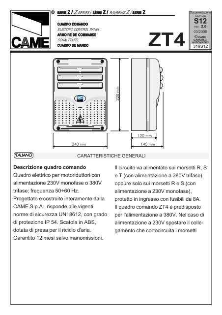
<strong>Descrizione</strong> <strong>quadro</strong> <strong>comando</strong><br />
<strong>Quadro</strong> <strong>elettrico</strong> <strong>per</strong> motoriduttori con<br />
alimentazione 230V monofase o 380V<br />
trifase; frequenza 50÷60 Hz.<br />
Progettato e costruito interamente dalla<br />
CAME S.p.A., risponde alle vigenti<br />
norme di sicurezza UNI 8612, con grado<br />
di protezione IP 54. Scatola in ABS,<br />
dotata di presa <strong>per</strong> il riciclo d'aria.<br />
Garantito 12 mesi salvo manomissioni.<br />
Il circuito va alimentato sui morsetti R, S<br />
e T (con alimentazione a 380V trifase)<br />
oppure solo sui morsetti R e S (con<br />
alimentazione a 230V monofase),<br />
protetto in ingresso con fusibili da 8A.<br />
Il <strong>quadro</strong> <strong>comando</strong> ZT4 è predisposto<br />
<strong>per</strong> l'alimentazione a 380V. Nel caso di<br />
alimentazione a 230V spostare il collegamento<br />
che cortocircuita i morsetti
«380» e «COM» sui morsetti «220» e<br />
«COM» (vedi pag.12).<br />
I dispositivi di <strong>comando</strong> sono a bassa<br />
tensione (24V), e sono protetti con<br />
fusibile da 2A. La potenza complessiva<br />
degli accessori a 24V, non deve su<strong>per</strong>are<br />
i 20W.<br />
Il tempo lavoro è fisso a 150 secondi.<br />
Sicurezza<br />
Le fotocellule possono essere collegate<br />
e predisposte <strong>per</strong>:<br />
- Ria<strong>per</strong>tura in fase di chiusura (2-C1);<br />
- Richiusura in fase di a<strong>per</strong>tura (2-CX,<br />
vedi dip 8-9);<br />
- Stop parziale, arresto del cancello se in<br />
movimento con conseguente predisposizione<br />
alla chiusura automatica<br />
(2-CX, vedi dip 8-9);<br />
- Stop totale (1-2), arresto del cancello<br />
con esclusione dell'eventuale ciclo di<br />
chiusura automatica; <strong>per</strong> riprendere il<br />
movimento bisogna agire sulla pulsantiera<br />
o sul radio<strong>comando</strong>;<br />
Nota: se un contatto di sicurezza normalmente<br />
chiuso (2-C1, 2-CX, 1-2) si<br />
apre, viene segnalato dal lampeggio del<br />
LED segnalazione.<br />
- Rilevazione di presenza ostacolo. A<br />
motore fermo (cancello chiuso, a<strong>per</strong>to o<br />
dopo un <strong>comando</strong> di stop totale), impedisce<br />
qualsiasi movimento se i dispositivi<br />
di sicurezza (es. fotocellule) rilevano un<br />
ostacolo;<br />
- Funzione del test di sicurezza. Ad ogni<br />
<strong>comando</strong> di a<strong>per</strong>tura e chiusura delle<br />
ante, la centralina verifica l'efficienza<br />
delle fotocellule (vedi pag.14).<br />
Accessori collegabili<br />
- Lampada ciclo o lampada di cortesia<br />
(60 Watt, vedi pag. 16);<br />
Altre funzioni selezionabili<br />
- Chiusura automatica. Il temporizzatore<br />
di chiusura automatica si autoalimenta a<br />
finecorsa in a<strong>per</strong>tura. Il tempo prefissato<br />
regolabile, é comunque subordinato<br />
all'intervento di eventuali accessori di<br />
sicurezza e si esclude dopo un intervento<br />
di «stop» totale o in mancanza di<br />
energia elettrica;<br />
- A<strong>per</strong>tura parziale. A<strong>per</strong>tura del cancello<br />
<strong>per</strong> passaggio pedonale, viene<br />
attivata collegandosi ai morsetti 2-3P ed<br />
è regolabile mediante trimmer<br />
AP.PARZ.. Con questa funzione, la<br />
chiusura automatica varia nel seguente<br />
modo:<br />
1) Dip 12 in ON: dopo un'a<strong>per</strong>tura<br />
parziale, il tempo di chiusura automatica<br />
è indipendente dalla regolazione del<br />
trimmer TCA e dalla posizione del dip 1,<br />
ed è fisso a 8 secondi.<br />
2) Dip 12 in OFF: dopo un'a<strong>per</strong>tura<br />
parziale, il tempo di chiusura è<br />
regolabile solo se il dip 1 è posizionato<br />
in ON;<br />
-2-
- Lampada ciclo. Lampada che illumina<br />
la zona di manovra, rimane accesa dal<br />
momento in cui l'anta inizia l'a<strong>per</strong>tura<br />
fino alla completa chiusura (compreso il<br />
tempo di chiusura automatica). Nel caso<br />
non sia inserita la chiusura automatica,<br />
rimane accesa solo durante il movimento<br />
(E-EX), vedi pag.16;<br />
- Lampada di cortesia. Lampada che<br />
illumina la zona di manovra, dopo un<br />
<strong>comando</strong> di a<strong>per</strong>tura rimane accesa con<br />
un tempo fisso di 5 minuti e 30 secondi<br />
(E-EX), vedi pag.16;<br />
- Funzione a "uomo presente". Funzionamento<br />
del cancello mantenendo<br />
premuto il pulsante (esclude il funzionamento<br />
del radio<strong>comando</strong>);<br />
- Prelampeggio di 5 secondi sia in<br />
a<strong>per</strong>tura sia in chiusura dell'anta;<br />
- Funzione master; il <strong>quadro</strong> assume<br />
tutte le funzioni di <strong>comando</strong> nel caso di<br />
due motori abbinati (vedi pagina 30);<br />
- Funzione slave; il <strong>quadro</strong> viene esclusivamente<br />
pilotato dal "MASTER" (vedi<br />
pagina 30);<br />
- Abilitazione alle funzioni di stop parziale<br />
o richiusura durante l'a<strong>per</strong>tura,<br />
contatto normalmente chiuso (2-CX),<br />
selezionare una delle due funzioni<br />
tramite dip (vedi selezioni funzioni);<br />
- Tipo di <strong>comando</strong>:<br />
-apre-chiude-inversione <strong>per</strong> pulsante e<br />
trasmettitore;<br />
-apre-stop-chiude-stop <strong>per</strong> pulsante e<br />
trasmettitore;<br />
-solo a<strong>per</strong>tura <strong>per</strong> trasmettitore.<br />
Regolazioni<br />
- Tempo chiusura automatica;<br />
- Tempo di a<strong>per</strong>tura parziale.<br />
Attenzione! Prima di intervenire<br />
all’interno dell’apparecchiatura, togliere<br />
la tensione di linea.<br />
-3-
ENGLISH<br />
GENERAL CHARACTERISTICS<br />
Description of control panel<br />
Control panel for gear motors, powered<br />
by 220V single-phase or 380V threephase;<br />
frequency 50-60 Hz.<br />
Designed and built entirely by CAME to<br />
meet UNI 8612 safety standards at an<br />
IP 54 level of protection.<br />
Housing in ABS is equipped with vents<br />
to provide internal air circulation.<br />
Guaranteed 12 months, unless<br />
tam<strong>per</strong>ed with.<br />
The power supply to the circuit should<br />
be connected to terminals R, S and T<br />
(with three-phase 380V power supply)<br />
or to terminals R and S only (singlephase<br />
220V power supply), is protected<br />
by a 8A fuse on the main power line.<br />
The ZT4 control panel is factory set for<br />
380V power supply. If the power supply<br />
is 220V, it is necessary to move the<br />
jum<strong>per</strong> which short-circuit terminals<br />
«380» and «COM» so that it shortcircuits<br />
terminals «220» and «COM»<br />
(see pag.12). The Control systems are<br />
powered by low voltage and protected<br />
with a 2A fuse. The total power<br />
consumption of 24 V accessories must<br />
not exceed 20W.<br />
Fixed o<strong>per</strong>ating time of 150 seconds.<br />
Safety<br />
Photocells can be connected to obtain:<br />
-Re-opening during the closing cycle (2-<br />
C1);<br />
-Re-closing during the opening cycle (2-<br />
CX, see dip 8-9);<br />
-Partial stop, shutdown of moving gate,<br />
with activation of an automatic closing<br />
cycle (2-CX, see dip 8-9);<br />
-Total stop (1-2), shutdown of gate<br />
movement without automatic closing; a<br />
pushbutton or radio remote control must<br />
be actuated to resume movement;<br />
N.B: If an NC safety contact (2-C1, 2-<br />
CX, 1-2) is opened, the LED will flash to<br />
indicate this fact;<br />
-Obstacle presence detection. When the<br />
motor is stopped (gate is closed, open<br />
or half-open after an emercency stop<br />
command), the transmitter and the<br />
control pushbutton will be deactivated if<br />
an obstacle is detected by one of the<br />
safety devices (for example, the<br />
photocells);<br />
-Safety test function. The control unit will<br />
now check the safety system every time<br />
an opening or closing command is given<br />
(see pag.14).<br />
Accessories which can be connected<br />
-Cycle lamp or courtesy light (60 Watt,<br />
see pag.16);<br />
Other functions<br />
-Automatic closing: The automatic<br />
closing timer is automatically activated<br />
at the end of the opening cycle. The<br />
preset, adjustable automatic closing<br />
-4-
time is automatically interrupted by the<br />
activation of any safety system, and is<br />
deactivated after a STOP command or<br />
in case of power failure;<br />
-Partial opening. Opening of the gate to<br />
allow for foot traffic; activated by<br />
connecting to terminals 2-3P and<br />
adjusted with the AP-PARZ. trimmer.<br />
With this function, the automatic closing<br />
can vary in the following way:<br />
1) Dip 12 set to ON: after a partial opening,<br />
the time for automatic closing functions<br />
independently of the adjustment of<br />
the TCA trimmer and of the position of<br />
Dip 1; it is set at 8 seconds.<br />
2) Dip 12 set to OFF: after a partial<br />
opening, the time for automatic closing<br />
is adjustable only if Dip 1 is set to ON.<br />
-Cycle lamp. The lamp which lights the<br />
manoeuvring zone: it remains lit from<br />
the moment the doors begin to open<br />
until they are completely closed<br />
(including the time required for the<br />
automatic closure). In case automatic<br />
closure is not enabled, the lamp remains<br />
lit only during movement (E-EX), see<br />
p.16;<br />
-Courtesy Light. A light that illuminates<br />
the manoeuvring zone; after an opening<br />
command, the light remains on for a<br />
fixed time of 5 minutes and 30 seconds<br />
(E-EX), see page 16;<br />
-"O<strong>per</strong>ator present" function: Gate<br />
o<strong>per</strong>ates only when the pushbutton is<br />
held down (the radio remote control<br />
system is deactivated);<br />
- Pre-flashing for 5 seconds, while the<br />
door is opening and closing;<br />
- Master function; the panel assumes all<br />
the command functions when two paired<br />
motors are used (see page 30);<br />
- Slave function; this panel is exclusively<br />
controlled by the “MASTER” (see page<br />
30);<br />
- Enabling functions of partial stop or reclosure<br />
during opening, normally-closed<br />
contact (2-CX), select one of the two<br />
functions by setting dip (see selection of<br />
functions);<br />
- Type of command:<br />
-open-close-reverse by button and<br />
transmitter;<br />
-open-stop-close-stop by button and<br />
transmitter;<br />
-open only by transmitter.<br />
Adjustments<br />
- Automatic closure time;<br />
- Partial opening time.<br />
Important! Disconnect the unit<br />
from the main power lines before<br />
carrying out any o<strong>per</strong>ation inside the<br />
unit.<br />
-5-
FRANÇAIS<br />
CARACTÉRISTIQUES GÉNÉRALES<br />
Description armoire de commande<br />
Armoire électrique pour motoréducteurs<br />
avec alimentation 220V monophasée ou<br />
380V triphasée; fréquence 50÷60 Hz.<br />
L’armoire est entièrement conçue et<br />
fabriquée par CAME S.p.A.<br />
conformément aux normes de sécurité<br />
en vigueur NFP 25-362 avec un degré<br />
de protection IP 54. Boîtier en ABS muni<br />
de prise de circulation d’air. Garantie 12<br />
mois sauf en cas d’endommagement.<br />
Le circuit doit être alimentè sur les<br />
bornes R, S et T (avec une alimentation<br />
à 380V triphasée) ou bien uniquement<br />
sur les bornes R et S (avec une<br />
alimentation à 220V monophasée), est<br />
protégée en entrée par un fusible de<br />
ligne de 8A. L'armoire de commande<br />
ZT4 est déjà prévue pour l'alimentation<br />
à 380V. Dans le cas d'une alimentation à<br />
220V, dèplacer la connexion qui courtcircuite<br />
les bornes «380» et «COM» sur<br />
les bornes «220» et «COM» (voir pàg.<br />
12). Les dispositifs de commande sont à<br />
basse tension et protégés avec fusible<br />
de 2A. La puissance totale des<br />
accessoires à 24V, ne doit pas dépasser<br />
20W.<br />
Temps de fonctionnement fixe de 150<br />
secondes.<br />
Sécurité<br />
Il est possible de brancher des photocellules<br />
et de les programmer pour:<br />
-Réouverture en phase de fermeture (2-<br />
C1);<br />
-Réfermeture en phase de ouverture (2-<br />
CX, voir dip 8-9);<br />
-Stop partiel, arrêt du portail, si en<br />
mouvement, et conséquente programmation<br />
pour la fermeture automatique<br />
(2-CX, voir dip 8-9);<br />
-Stop total (1-2) arrêt du portail et<br />
désactivation d’un éventuel cycle de<br />
fermeture automatique; pour activer de<br />
nouveau le mouvement, il faut agir sur<br />
les boutons-poussoirs ou sur la radiocommande);<br />
Remarque: Le voyant de signalisation<br />
qui clignote indique qu'un contact de<br />
sécurité normalment fermé (2-C1, 2-CX,<br />
1-2) s'ouvre.<br />
-Détection de présence obstacle. Quand<br />
le moteur est arrête (portail fermé,<br />
ouvert ou semi-ouvert, cette position est<br />
obtenue avec une commande de stop<br />
total), annule toute fonction de<br />
l'émetteur ou du bouton-poussoir en cas<br />
d'obstacle détecté par les dispositifs de<br />
sécurité (ex. Photocellules);<br />
-Fonction du test de securité. Cela<br />
<strong>per</strong>met au boîtier de vérifier le bon<br />
fonctionnement des despositifs de<br />
securité aprés chaque commande<br />
d'ouverture ou de fermeture (voir pag.<br />
14);<br />
Accessoires pouvant être branchés<br />
-Lampe cycle ou lampe passage (60<br />
Watt, voir pag.16);<br />
-6-
Autres fonctions<br />
-Fermeture automatique. Le temporisateur<br />
de fermeture automatique est<br />
autoalimenté à la fin du temps de la<br />
course en ouverture. Le temps réglable<br />
est programmé, cependant, il est<br />
subordonné à l’intervention d’éventuels<br />
accessoires de sécurité et il est exclu<br />
après une intervention de “stop” ou en<br />
cas de coupure de courant;<br />
-Ouverture partielle. Ouverture de la<br />
grille pour le passage pour piétons, elle<br />
est enclenchée en la reliant aux bornes<br />
2-3P et est réglable par le trimmer<br />
AP.PARZ.. Avec cette fonction, la fermeture<br />
automatique varie de la façon suivante<br />
:<br />
1) Dip 12 sur ON : après une ouverture<br />
partielle, le temps de fermeture automatique<br />
est indépendant du réglage du<br />
trimmer TCA et de la position du dip 1,<br />
et est fixe à 8 secondes.<br />
2) Dip 12 sur OFF : après une ouverture<br />
partielle, le temps de fermeture automatique<br />
est réglable seulement si le dip 1<br />
est positionné sur ON;<br />
-Lampe cycle. Ampoule qui illumine la<br />
zone de manoeuvre: elle reste allumée<br />
à partir du moment ou les portes<br />
commencent l'ouverture jusqu'à la<br />
fermeture complète (y compris le temps<br />
de fermeture automatique). Si elle n'est<br />
pas insérée la fermeture automatique<br />
reste allumée seulement durant le<br />
mouvement (E-EX), voir pag.16;<br />
-Lampe passage. Lampe qui illumine la<br />
zone de manoeuvre, après une commande<br />
d’ouverture elle reste allumée<br />
pour une durée fixe de 5 minutes et 30<br />
secondes (E-EX), voir p.16;<br />
-Fonction “homme mort”. Fonctionnement<br />
du portail en maintenant appuyé<br />
le bouton-poussoir (exclut la fonction de<br />
la radiocommande);<br />
-Prè-clignotement de 5 secondes en<br />
ouverture comme en fermeture de la<br />
porte;<br />
-Fonction master; le pupitre prend toutes<br />
les fonctions de commande si les<br />
deux moteurs sont mis ensemble (voir<br />
p.30);<br />
-Fonction slave; le pupitre est exclusivement<br />
piloté par le “ MASTER ” (voir<br />
page 30);<br />
- Activation des fonctions d'arrêt partiel<br />
ou de fermeture durant l'ouverture,<br />
contact normalment fermé (2-CX),<br />
sélectionner une des deux fonctions à<br />
l'aide d'un dip (voir sélection fonctions);<br />
-Type de commande:<br />
-ouvre-ferme-inversion pour bouton et<br />
émetteur;<br />
-ouvre-stop-ferme-stop pour bouton et<br />
émetteur;<br />
-seulement ouverture pour émetteur.<br />
Réglages<br />
- Temps de fermeture automatique;<br />
- Temps d’ouverture partielle.<br />
Attention! Avant d’intervenir à<br />
l’intérieur de l’appareillage, cou<strong>per</strong> la<br />
tension de ligne.<br />
-7-
DEUTSCH<br />
ALLGEMEINE MERKMALE<br />
Beschreibung des Steuergeräts<br />
Schalttafel für Getriebemotoren mit 220-<br />
V-Einphasenstromversorgung oder 380-<br />
V-Dreiphasenstromversorgung;<br />
Frequenz: 50-60 Hz.<br />
Vollkommen von der CAME S.p.A. den<br />
geltenden Sicherheitsnormen (UNI<br />
8612) entsprechend entwickelt und<br />
hergestellt. Schutzgrad: IP 54. ABS-<br />
Gehäuse mit Luftklappe. 12 Monate<br />
Garantie, vorbehaltlich unsachgemäßer<br />
Handhabung und Montage.<br />
Der Stromkreis wird über die Klemmen<br />
R, S und T (bei Stromversorgung 380V<br />
dreiphasing) oder nur über die Klemmen<br />
R und S (bei Stromversorgung 220V<br />
einphasing) mit Stromversorgt, am<br />
Eingang mit einer 8A-Hauptsicherung.<br />
Das Steuergerät ZT4 wird werkseits für<br />
380V Stromversorgung vorbereitet. Bei<br />
220V Stromanschluß, den Anschluß,<br />
der die Klemmen «380» und «COM»<br />
kurzschließt auf die Klemmen «220»<br />
und «COM» umklemmen (siehe Seite<br />
12). Die Steuerungen erfolgen mit<br />
Niederspannung und geschützen enie<br />
2A-Sicherung. Die Gesamtleistung des<br />
24-V-Zubehörs darf 20W nicht<br />
überschreiten.<br />
Feste Laufzeit von 150 Sekunden.<br />
Sicherheitsvorrichtungen<br />
Die Lichtschranken können für folgende<br />
Funktionen angeschlossen bzw.<br />
vorbereitet werden:<br />
-Wiederöffnen beim Schließen (2-C1);<br />
-Wiederschließen beim Öffnen (2-CX,<br />
siehe dip 8-9);<br />
-Teilstop, Stillstand des Tores während<br />
des Torlaufs, mit darauffolgender<br />
automatischer Torschließung (2-CX,<br />
siehe dip 8-9);<br />
-Totalstop (1-2), sofortiger Stillstand<br />
des Tores mit Ausschluß eventueller<br />
Schließautomatik: Fortsetzung des<br />
Torlaufs über Drucktaster- bzw. Funksteuerung;<br />
Hinweis: Wenn sich ein normalerweise<br />
geschlossener (NC) Sicherheitskontakt<br />
(2-C1, 2-CX, 1-2) öffnet, wird dies durch<br />
Blinken der Kontrolleuchte angezeigt.<br />
-Ermittlung eventuell vorhandener<br />
Hindernisse. Bei stillstehendem Motor<br />
(Tor geschlossen, geöffnet oder durch<br />
eine Totalstop-Steuerung halb geöffnet)<br />
wird bei durch die Sicherheitsvorrichtungen<br />
(z.B.:Lichtschranken)<br />
erfaßtem Hindernis jede Sensor-oder<br />
Drucktasterfunktion annulliert;<br />
-Sicherheitstest-Funktion. Dadurch<br />
besteht die Möglichkeit, die<br />
Leistungsfähigkeit der Sicherheitsvorrichtungen<br />
nach jeder Öffnungs-und<br />
Schließsteuerung zu überprüfen (siehe<br />
Seite 14).<br />
Anschließbares Zubehör<br />
-Betriebszyklus-Anzeigeleuchte oder<br />
Torbeleuchtung (60 Watt, siehe S.16);<br />
Andere funktionen<br />
-Schließautomatik. Der Schließ-<br />
-8-
automatik-Zeischalter speist sich beim<br />
Öffnen am Ende der Torlaufzeit selbst.<br />
Die voreingestellte Zeit ist auf jeden Fall<br />
immer dem Eingriff eventueller<br />
Sicherheitsvorrichtungen untergeordnet<br />
und schließt sich nach einem “Stop”-<br />
Eingriff bzw. bei Stromausfall selbst aus;<br />
-Teilweises Öffnung. Das Öffnen des<br />
Tors für das Durchlassen von<br />
Fußgängern wird durch Anschluß an die<br />
Klemmen 2-3P aktiviert und kann über<br />
den Trimmer AP.PARZ. eingestellt<br />
werden. Wenn diese Funktion aktiviert<br />
ist, variiert das automatische Schließen<br />
folgendermaßen:<br />
1)Dip 12 auf ON: Nach einem teilweisen<br />
Öffnen erfolgt das Schließen des Tor<br />
unabhängig von der Einstellung des<br />
Trimmer TCA und der Stellung des Dip-<br />
Switch 1, und zwar nach einer<br />
vorgegebenen Zeit von 8 Sekunden;<br />
2)Dip 12 auf OFF: Nach einem<br />
teilweisen Öffnen kann die Zeit für das<br />
automatische Schließen nur dann<br />
eingestellt werden, wenn der Dip-Switch<br />
1 auf ON steht;<br />
-Betriebszyklus-Anzeigeleuchte. Das<br />
Licht, das den Torbereich beleuchtet,<br />
bleibt vom Beginn des Öffnens bis zum<br />
vollständigen Schließen der Torflügel<br />
eingeschaltet (einschließlich Wartezeit<br />
für automatisches Schließen). Wenn das<br />
automatische Schließen nicht<br />
zugeschaltet ist, bleibt das Licht nur<br />
während der Torbewegung eingeschaltet<br />
(E-EX),siehe S.16;<br />
-Torbeleuchtung. Nachdem der Befehl<br />
zum Öffnen des Tors gegeben worden<br />
ist, bleibt das Licht, das den Manöverbereich<br />
am Tor beleuchtet, für eine<br />
vorgegebene Zeit von 5 Minuten und 30<br />
Sekunden eingeschaltet (E-EX), siehe<br />
S. 16;<br />
-Funktion “Bedienung vom Steuerpult”.<br />
Torbetrieb durch Drucktasterbetätigung<br />
(Funkfernsteuerung ausgeschlossen);<br />
-Vorblinken. Das Licht blinkt sowohl vor<br />
dem Öffnen als auch vor dem Schließen<br />
zunächst 5 Sekunden lang;<br />
-Master-Funktion (übergeordnet). Wenn<br />
zwei Motoren kombiniert werden,<br />
übernimmt die Schalttafel alle<br />
Steuerungsfunktionen (siehe S.30);<br />
-Slave-Funktion (untergeordnet). Die<br />
Schalttafel unterliegt komplett der<br />
Steuerung durch die MASTER-<br />
Schalttafel (siehe S.30);<br />
- Zum Aktivieren der Funktionen<br />
teilweiser Stop oder erneutes Schließen<br />
während der Öffnungsphase (NC-<br />
Kontakt 2-CX) bitte eine der beiden<br />
Funktionen mithilfe vom Dip wählen<br />
(siehe Funktionswahl);<br />
-Befehlsarten:<br />
-Öffnen-Schließen-Inversion für Druckknopf<br />
und Sender;<br />
-Öffnen-Stop-Schließen-Stop für Druckknopf<br />
und Sender;<br />
-nur Öffnen für Sender.<br />
Einstellungen<br />
- Zeit für das automatische Schließen;<br />
- Zeit für das teilweise Öffnen.<br />
Achtung! vor Eingriff im Innern<br />
des Gerätes den Netzstecken ziehen.<br />
-9-
ESPANOL<br />
CARACTERISTICAS GENERALES<br />
Descripción cuadro de mando<br />
Cuadro eléctrico para motorreductores<br />
con alimentación 220V monofásica o<br />
230V trifásica: frecuencia 50÷60 Hz.<br />
Diseñado y fabricado enteramente por<br />
CAME S.p.A., cumple con las normas<br />
de seguridad vigentes UNI 8612, con<br />
grado de protección IP 54. Caja de ABS,<br />
dotada de toma para la recirculación de<br />
aire. Garantizado 12 meses salvo<br />
manipulaciones.<br />
El circuito se debe alimentar en los<br />
bornes R, S y T (con alimentación de<br />
380V trifásica) o bien sólo en los bornes<br />
R y S (con alimentación de220V<br />
monofásica), está protegido en entrada<br />
con fusible de línea de 8A. El cuadro de<br />
mando ZT4 viene ya dispuesto para la<br />
alimentación de 380V. Caso de que se<br />
alimente con 220V, desplazar la<br />
conexión que cortocircuita los bornes<br />
«380» y «COM» en los bornes «220» y<br />
«COM» (vèase pàg.12). Los<br />
dispositivos de mando son a baja<br />
tensión y està protegidos por fusible a<br />
2A. La potencia total de los accesorios a<br />
24V, no debe su<strong>per</strong>ar los 20W.<br />
Tiempo de trabajo fijo a 150 segundos.<br />
Seguridad<br />
Las fotocélulas pueden estar<br />
conectadas y predispuestas para:<br />
-Rea<strong>per</strong>tura en la fase de cierre (2-C1);<br />
-Recierre en la fase de a<strong>per</strong>tura (2-CX,<br />
ver dip 8-9);<br />
-Parada parcial, parada de la puerta si<br />
se encuentra en movimiento con la<br />
consiguiente predisposición al cierre<br />
automático (2-CX, ver dip 8-9);<br />
-Parada total (1-2), parada de la puerta<br />
excluyendo el posible ciclo de cierre<br />
automático; para reactivar el movimiento<br />
es preciso actuar en el teclado o en el<br />
mando a distancia);<br />
Nota: La a<strong>per</strong>tura de un contacto de<br />
seguridad normalmente cerrado (2-C1,<br />
2-CX, 1-2) es señalada por medio del<br />
destello del LED de señalización.<br />
-Detección de presencia obstáculo. Con<br />
el motor parado (puerta cerrada, abierta<br />
o en posición semi-abierta obtenida a<br />
través de un <strong>comando</strong> de stop total),<br />
anula cualquier función del transmisor o<br />
del botón en caso de obstáculo<br />
detectado por los dispositivos de<br />
seguridad (por ejemplo: fotocélulas);<br />
-Función de las pruebas de seguridad.<br />
Permite a la central comprobar la<br />
eficiencia en los dispositivos de<br />
seguridad después de cada <strong>comando</strong><br />
de a<strong>per</strong>tura y cierre (véase pág.14).<br />
Accesorios conectables<br />
-Làmpara ciclo o luz de cortesía (60<br />
Watt, véase pág.16);<br />
Otras funciones<br />
-Cierre automático. El temporizador de<br />
cierre automático se autoalimenta en<br />
fin-de-tiempo carrera en fase de a<strong>per</strong>tu-<br />
-10-
a. El tiempo prefijado regulable, sin<br />
embargo, está subordinado a la<br />
intervención de posibles accesorios de<br />
seguridad y se excluye después de una<br />
intervención de parada o en caso de<br />
falta de energía eléctrica;<br />
-A<strong>per</strong>tura parcial. La a<strong>per</strong>tura de la verja<br />
para el paso peatonal, se activa<br />
conectando los bornes 2-3P y puede<br />
ser regulada por medio del trimmer<br />
AP.PARZ. Con dicha función el cierre<br />
automático se modifica de la siguiente<br />
manera:<br />
1) Dip 12 en ON: luego de una a<strong>per</strong>tura<br />
parcial, el tiempo de cierre automático<br />
es independiente de la regulación del<br />
trimmer TCA y de la posición del dip 1 y<br />
queda fijo en 8 segundos;<br />
2) Dip 12 en OFF: luego de una a<strong>per</strong>tura<br />
parcial, el tiempo de cierre<br />
automático puede ser regulado sólo si el<br />
dip 1 está colocado en ON;<br />
-Lámpara ciclo. Lámpara que alumbra la<br />
zona de maniobra: se queda encendida<br />
a partir del momento en que las hojas<br />
empiezan la a<strong>per</strong>tura hasta el cierre<br />
completo (incluyendo el tiempo de cierre<br />
automático). Si no se habilita el cierre<br />
automático, el cierre <strong>per</strong>manece<br />
encendido sólo durante el movimiento<br />
(E-EX), véase pág.16;<br />
-Luz de cortesía. Lámpara que ilumina<br />
la zona de maniobra; tras un mando de<br />
a<strong>per</strong>tura <strong>per</strong>manece encendida por 5<br />
minutos y 30 segundos (E-EX), véase<br />
pág.16;<br />
-Función a "hombre presente". Funcionamiento<br />
de la puerta manteniendo<br />
pulsada la tecla (excluye la función del<br />
mando a distancia);<br />
-Intermitencia previa de 5 segundos tanto<br />
en el momento de a<strong>per</strong>tura como de<br />
cierre de la puerta;<br />
-Función master; el cuadro asume todas<br />
las funciones de mando en el caso de<br />
dos motores combinados (véase página<br />
30);<br />
-Función slave; el cuadro es accionado<br />
exclusivamente por el “MASTER”<br />
(véase página 30);<br />
- Habilitación para las funciones de<br />
parada parcial o cierre durante la a<strong>per</strong>tura,<br />
contacto normalmente cerrado (2-<br />
CX), seleccionar una de las dos<br />
funciones mediante Dip (ver selección<br />
de las funciones);<br />
-Tipo de mando:<br />
-abrir-cerrar-inversión para botón y<br />
transmisor;<br />
-abrir-stop-cerrar-stop para botón y<br />
transmisor;<br />
-sólo a<strong>per</strong>tura para transmisor.<br />
Regulaciones<br />
- Tiempo de cierre automático;<br />
- Tiempo de a<strong>per</strong>tura parcial.<br />
¡Atención! Antes de actuar dentro<br />
del aparato, quitar la tensión de<br />
línea.<br />
-11-
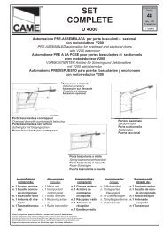
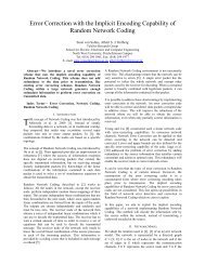
SCHEDA BASE - MOTHERBOARD - CARTE BASE - GRUNDPLATINE - TARJETA BASE<br />
Collegamento predisposto <strong>per</strong> l'alimentazione del <strong>quadro</strong> <strong>comando</strong> a 380V<br />
Connection for 380V power supply to control panel<br />
Connexion prévue pour l'alimentation de l'armoire de commande à 380V<br />
Vorgesehener Anschluß für 380V Stromversorgung des Steuergerätes<br />
Conexión dispuesta para la alimentación del cuadro de mando de 380V<br />
DIS. 25215<br />
T.C.A.<br />
AP.PARZ.<br />
8<br />
7<br />
2<br />
FUS.LINEA 5A<br />
FUSIBILE<br />
ACCESSORI 2A<br />
3<br />
ON<br />
1 2 3 4 5 6 7 8 9 10<br />
ON<br />
11 12 13 14 15 16 17 18 19 20<br />
6<br />
ZT4<br />
5<br />
CH1<br />
CH2<br />
9<br />
4<br />
AF<br />
R S T U V W R<br />
O<br />
S<br />
S<br />
O<br />
220V<br />
B<br />
I<br />
A<br />
N<br />
C<br />
O<br />
B<br />
L<br />
U<br />
3<br />
8<br />
0<br />
2<br />
2<br />
0<br />
C<br />
O<br />
M<br />
1<br />
Nel caso di alimentazione del <strong>quadro</strong> <strong>comando</strong><br />
a 230V, cortocircuitare i morsetti 220 - COM<br />
Connection for 230V power supply to control panel,<br />
short-circuit terminals 220 - COM<br />
Dans le cas d'une alimentation de l'armoire de<br />
commande à 230V, court-circuiter les bornes<br />
220 - COM<br />
Im Falle von 230V Stromversorgung des<br />
Steuergerätes, die Klemmen 220 - COM<br />
kurzschließen<br />
Caso de que se alimente el cuadro de mando<br />
con 230V, cortocircuitar los bornes 220 - COM<br />
Frequenza / MHz<br />
Frequency / MHz<br />
Frequence / MHz<br />
Frequenz / MHz<br />
Frecuencia / MHz<br />
Scheda radiofrequenza<br />
Radiofrequency board<br />
Carte radiofréquence<br />
Funkfrequenz-Platine<br />
Tarjeta radiofrecuencia<br />
Trasmettirore<br />
Transmitter<br />
Emetteur<br />
Funksender<br />
Transmisor<br />
FM 26.995 AF130 TFM<br />
FM 30.900 AF150 TFM<br />
AM 26.995 AF26 TOP<br />
AM 30.900 AF30 TOP<br />
AM 433.92 AF43S / AF43SM TAM / TOP<br />
ITALIANO<br />
-12-<br />
COMPONENTI PRINCIPALI<br />
1 Morsettiere di collegamento<br />
2 Fusibili di linea 8A<br />
3 Fusibile accessori 2A<br />
4 Innesto scheda radiofrequenza AF (vedi tabella)<br />
5 Pulsanti memorizzazione codice radio<br />
6 Dip-switch "selezione funzioni"<br />
7 Trimmer AP.PARZ.: regolazione a<strong>per</strong>tura parziale<br />
8 Trimmer TCA: regolazione tempo di chiusura automatica<br />
9 LED di segnalazione codice radio
ENGLISH<br />
MAIN COMPONENTS<br />
1 Terminal block for external connections<br />
2 8A line fuse<br />
3 2A accessories fuse<br />
4 Socket AF radiofrequency board (see table)<br />
5 Radio-code save buttons<br />
6 "Function selection" Dip-switch<br />
7 Trimmer AP.PARZ.: Partial opening adjustment<br />
8 Trimmer TCA: automatic closing time adjustment<br />
9 Radio-code LED<br />
FRANÇAIS<br />
COMPOSANTS PRINCIPAUX<br />
1 Plaque à bornes pour les branchements<br />
2 Fusibles de ligne 8A<br />
3 Fusible accessoires 2A<br />
4 Branchement carte radiofréquence AF (voir tableau)<br />
5 Boutons mise en mémoire code radio et programmation<br />
6 Dip-switch "sélection fonction"<br />
7 Trimmer AP.PARZ.: réglage ouverture partielle<br />
8 Trimmer TCA: réglage temps de fermeture automatique<br />
9 LED de segnalisation code radio<br />
DEUTSCH<br />
HAUPTKOMPONENTEN<br />
1 Anschluss-Klemmenleiste<br />
2 8A-Sicherung Leitungs<br />
3 2A-Sicherung Zubehörs<br />
4 Steckanschluß Funkfrequenze-Platine AF (sehen Tabelle)<br />
5 Knöpfe zum Abspeichern der Radiocodes<br />
6 "Funktionswahl" Dip-switch<br />
7 Trimmer AP.PARZ.: Einstellung Teilöffnung<br />
8 Trimmer TCA: Einstellung Zeiteinstellung Schließautomatik<br />
9 LED Kontrolleuchte zur Anzeige von Radiocode<br />
ESPANOL<br />
COMPONENTES PRINCIPALES<br />
1 Caja de bornes para las conexiónes<br />
2 Fusibles de línea 8A<br />
3 Fusible accesorios 2A<br />
4 Conexión tarjeta radiofrecuencia AF (vedas tabla)<br />
5 Botones de memorización del código radio<br />
6 Dip-switch "seleción función"<br />
7 Trimmer AP.PARZ.: regulación a<strong>per</strong>tura parcial<br />
8 Trimmer TCA: regulación cierre automático<br />
9 Indicador luminoso código radio<br />
-13-
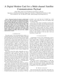
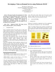
TEST FUNZIONAMENTO FOTOCELLULE / PHOTOCELL FUNCTION TEST<br />
TEST FONCTIONNEMENT PHOTOCELLULES<br />
TEST FÜR DAS FUNKTIONIEREN DER LICHTSCHRANKEN / TEST FUNCIONAMIENTO FOTOCELULAS<br />
«DOC»<br />
+ - + -<br />
N.O.<br />
C.<br />
N.C.<br />
E4 10 11 TS 1 2 3 3P 4 5 6 7 2MOT<br />
ITALIANO<br />
Consente alla centralina di verificare<br />
l'efficenza dei dispositivi di sicurezza<br />
(fotocellule) dopo ogni <strong>comando</strong> di<br />
a<strong>per</strong>tura o di chiusura. Un eventuale<br />
anomalia delle fotocellule viene identificata<br />
con un lampeggio del led sul<br />
<strong>quadro</strong> <strong>comando</strong>, di conseguenza<br />
annulla qualsiasi funzione del<br />
radio<strong>comando</strong> e del pulsante.<br />
Collegamento <strong>elettrico</strong> <strong>per</strong> il funzionamento<br />
del test di sicurezza:<br />
I trasmettitori e i ricevitori delle<br />
fotocellule devono essere collegati nel<br />
seguente modo:<br />
- il trasmettitore della fotocellula collegato<br />
sui morsetti TS-10, mentre il ricevitore<br />
collegato sui morsetti 10-11 (vedi<br />
disegno).<br />
- selezionare il dip 13 in ON <strong>per</strong> attivare<br />
il funzionamento del test.<br />
IMPORTANTE: Quando si esegue la<br />
funzione test di sicurezza, VERIFICARE<br />
che NON CI SIANO PONTI tra i contatti<br />
2-CX, 2-C1 e, se non utilizzati, escluderli<br />
tramite dip 7 e 8.<br />
ENGLISH<br />
The control unit will now check the<br />
safety system (photocells) every time an<br />
opening or closing command is given. If<br />
a photocell malfunctions, a LED will<br />
flash on the control panel, and the radio<br />
transmitter and the control pushbutton<br />
will be deactivated.<br />
Electrical connections required for<br />
safety test function.<br />
Photocell lamps and sensors must be<br />
connected as follows:<br />
- connect the photocell sensor across<br />
terminals TS-10. Connect the photocell<br />
lamp across terminals 10-11 (see<br />
diagram);<br />
- move dip switch 13 to ON, which will<br />
activate the test function.<br />
IMPORTANT: When the safety test is<br />
enabled, CHECK that THERE ARE NO<br />
JUMPERS between contacts 2-CX, 2-<br />
C1 and, if not being used, exclude them<br />
using dip switches 7 and 8.<br />
-14-
FRANÇAIS<br />
Cela <strong>per</strong>met au boîtier de vérifier le bon<br />
fonctionnement des dispositifs de<br />
sécurité (photocellules) aprés chaque<br />
commande d'ouverture ou de fermeture.<br />
Les éventuelles anomalies des<br />
photocellules sont signalées par un<br />
clignotement de la led sur l'armoire de<br />
commande, et la conséquente<br />
annulation de toute fonction de<br />
l'émetteur et du bouton-poussoir.<br />
Branchement électrique pour le<br />
fonctionnement du test de sécurité.<br />
Les émetteurs et les récepteurs des<br />
photocellules doivent être branchés de<br />
la manière suivante:<br />
- l'émmetteur de la photocellule sur le<br />
bornes TS-10, celui du récepteur sur les<br />
bornes 10-11 (voir dessin);<br />
- mettre le dip-switch 13 sur ON pour<br />
activer le fonctionnement du test.<br />
IMPORTANT: Quand on active la<br />
fonction test de sécurité, VERIFIER qu'il<br />
N'Y A PAS DE PONTS entre les<br />
contacts 2-CX, 2-C1 et, s'ils ne sont pas<br />
utilisés, les exclure à l'aide des<br />
interrupteurs à positions multiples 7 et<br />
8.<br />
DEUTSCH<br />
Dadurch besteht die Möglichkeit, die<br />
Leistungsfähigkeit der<br />
Sicherheitsvorrichtungen<br />
(Lichtschranken) nach jeder Öffnungsund<br />
Schließsteuerung zu überprüfen.<br />
Bei eventuell auftretenden<br />
Betriebsstörungen der Lichtschranken<br />
leuchtet die entsprechende LED auf<br />
dem Steuergerät auf und jede<br />
Funksender- und Drucktaster-Funktion<br />
wird automatisch annulliert.<br />
Elektrischer Anschluß für die<br />
Sicherheitstest-Funktion.<br />
Die Sender und Empfänger der<br />
Lichtschranken folgendermaßen<br />
anschließen:<br />
- Lichtschrankensender auf den<br />
Klemmen TS-10, Empfänger auf den<br />
Klemmen 10-11 (siehe Abbildung)<br />
- Dip-Switch 13 zur Aktivierung der<br />
Sicherheitstest-Funktion auf ON stellen.<br />
ACHTUNG: Wenn die Funktion<br />
Sicherheitstest gestartet wird, muß<br />
KONTROLLIERT werden, daß es<br />
zwischen den Kontakten 2-CX und 2-C1<br />
KEINE BRÜCKEN GIBT. Falls die<br />
Kontakten nicht verwendet werden,<br />
müssen Sie mit Dip 7 und 8<br />
ausgeschlossen werden.<br />
ESPANOL<br />
Permite a la central comprobar la<br />
eficiencia en los dispositivos de<br />
seguridad (fotocélulas) después de<br />
cada <strong>comando</strong> de a<strong>per</strong>tura y cierre. Una<br />
posible anomalía de las fotocélulas se<br />
indica a través de una luz parpadeante<br />
del LED en el cuadro de mando y, por lo<br />
tanto, se anula cualquier función del<br />
transmisor y de la tecla.<br />
Conexión eléctrica para el<br />
funcionamiento de las pruebas de<br />
seguridad.<br />
Los transmisores y los receptores de<br />
las fotocélulas deben estar conectados<br />
de la siguiente manera:<br />
- el transmisor de la fotocélula<br />
conectado a los bornes TS-10, el<br />
receptor a los bornes 10-11 (ver dibujo);<br />
- seleccionar el dip 13 en ON para<br />
activar el funcionamiento de la prueba.<br />
IMPORTANTE: Al activarse la función<br />
test de seguridad, CONTROLAR que<br />
NO HAYA PUENTES entre los<br />
contactos 2-CX, 2-C1 y, si no se<br />
utilizan, inhabilitarlos mediante los dip 7<br />
y 8.<br />
-15-
COLLEGAMENTI ELETTRICI - ELECTRICAL CONNECTIONS - BRANCHEMENTS ÉLECTRIQUES<br />
ELEKRISCHE ANSCHLÜSSE - CONEXIONES ELÉCTRICAS<br />
R S T U V W E E1 EX E4 10 11 TS 1 2 3 3P 4 5 6 7 2MOT FC FA F 2 C1 CX B1 B2<br />
R<br />
S<br />
Alimentazione 230V (a.c.) monofase (220-COM)<br />
230V (a.c.) power input single-phase (220-COM)<br />
Alimentation 230V (c.a.) monophasée (220-COM)<br />
Stromversorgung 230V (Wechselstrom) einphaseing (220-COM)<br />
Alimentación 230V (a.c.) monofásica (220 -COM)<br />
R<br />
S<br />
T<br />
Alimentazione 380V (a.c.) trifase (380-COM)<br />
380V (a.c.) power input three-phase (380-COM)<br />
Alimentation 380V (c.a.) triphasée (380-COM)<br />
Stromversorgung 380V (Wechselstrom) dreiphaseing (380-COM)<br />
Alimentación 380V (a.c.) trifásica (380 -COM)<br />
U<br />
W<br />
V<br />
Motore monofase/trifase 230/380V (a.c.)<br />
230/380V (a.c.) single-phase/three-phase motor<br />
Moteur monophasé/triphasée 230/380V (c.a.)<br />
Motor einphasen/dreiphasen 230/380V (Wechselstrom)<br />
Motor monofàsico/trifásico 230/380V (a.c.)<br />
E<br />
E1<br />
Uscita 230V (a.c.) in movimento<br />
(es.lampeggiatore - max. 25W)<br />
230V (a.c.) output in motion<br />
(e.g. flashing light - max. 25W)<br />
Sortie 230V (c.a.) en mouvement<br />
(ex. branchement clignotant - max. 25W)<br />
Ausgang 230V (Wechselstrom) in Bewegung<br />
(z.B. Blinker-Anschluß - max. 25W)<br />
Salida de 230V (a.c.) en movimento<br />
(p.ej. conexión lámpara intermitente - max. 25W)<br />
E<br />
EX<br />
-16-<br />
Lampada ciclo (230V)<br />
o cortesia (230V)<br />
(230V) cycle lamp or (230V)<br />
courtesy light<br />
Lampe cycle (230V)<br />
ou lampe passage (230V)<br />
Betriebszyklus-Anzeigeleuchte<br />
oder Torbeleuchtung (230V)<br />
Lámpara ciclo (230V)<br />
o luz de cortesía (230V)<br />
LAMPADA CORTESIA<br />
COURTESY LIGHT<br />
LAMPE PASSAGE<br />
TORBELEUCHTUNG<br />
LUZ DE CORTESIA<br />
(16 ON - 17 OFF)<br />
O 11 12 13 14 15 16 17 18 19 20<br />
N<br />
LAMPADA CICLO<br />
CYCLE LAMP<br />
LAMPE CYCLE<br />
BETRIEBSZYKLUS-ANZEIGELEUCHTE<br />
LAMPARA CICLO<br />
(17 ON - 16 OFF)<br />
MAX.<br />
60<br />
WATT<br />
V W E E1 EX
10<br />
11<br />
1<br />
2<br />
2<br />
3<br />
2<br />
3P<br />
5<br />
11<br />
6<br />
11<br />
10<br />
E4<br />
Alimentazione accessori 24V (a.c.) max. 20W<br />
24V (a.c.)Powering accessories (max 20W)<br />
Alimentation accessoires 24V (c.a.) max. 20W<br />
Zubehörspeisung 24V (Wechselstrom) max. 20W<br />
Alimentación accesoios 24V (a.c.) max. 20W<br />
Pulsante stop (N.C.)<br />
Pushbutton stop (N.C.)<br />
Bouton-poussoir arrêt (N.F.)<br />
Stop-Taste (N.C.)<br />
Pulsador de stop (N.C.)<br />
Pulsante apre (N.O.)<br />
Pushbutton opens (N.O.)<br />
Bouton-possoir ouverture (N.O.)<br />
Taste Öffnen (Arbeitskontakt)<br />
Pulsador de a<strong>per</strong>tura (N.O.)<br />
Pulsante <strong>per</strong> a<strong>per</strong>tura parziale (N.O.)<br />
Open button (N.O.) for partial opening<br />
Bouton-poussoir d'ouverture (N.O.) pour ouverture partial<br />
Taste Öffnen (Arbeitskontakt) für TeilÖffnung<br />
Pulsador de a<strong>per</strong>tura (N.O.) para a<strong>per</strong>ture parcial<br />
Lampada spia (24V-3W max.) "cancello a<strong>per</strong>to"<br />
(24V-3W max.) "gate-opened" signal lamp<br />
Lampe-témoin (24V-3W max.) "portail ouverture"<br />
Signallampe (24V-3W max.) "Tor Öffnen"<br />
Lampada indicadora (24V-3W max.) "puerta abierto"<br />
Lampada spia (24V-3W max.) "cancello chiuso"<br />
(24V-3W max.) "gate-closed" signal lamp<br />
Lampe-témoin (24V-3W max.) "portail fermeture"<br />
Signallampe (24V-3W max.) "Tor Schließen"<br />
Lampada indicadora (24V-3W max.) "puerta cierre"<br />
Uscita 24V (a.c.) in movimento<br />
24V (a.c.) output in motion<br />
Sortie 24V (c.a.) en mouvement<br />
Ausgang 24V (Wechselstrom) in Bewegung<br />
Salida de 24V (a.c.) en movimento<br />
2<br />
4<br />
Pulsante di chiusura (N.O.)<br />
Close pushbutton (N.O.)<br />
Bouton-poussoir de fermeture (N.O.)<br />
Taste Schließen (Arbeitskontakt)<br />
Pulsador de cierre (N.O.)<br />
-17-
2<br />
7<br />
2<br />
C1<br />
2<br />
CX<br />
Contatto radio e/o pulsante <strong>per</strong> <strong>comando</strong> (vedi dipswitch<br />
2-3 sel.funzioni)<br />
Contact radio and/or button for control (see dip-switch 2-3<br />
function selection)<br />
Contact radio et/ou poussoir pour commande (dipswitch<br />
2-3 sel.fonction)<br />
Funkkontakt und/oder Taste Steuerart (dip-switch 2-3<br />
Funktionswahl)<br />
Contacto radio y/o pulsador para mando (dip-switch 2-<br />
3 seleción fonción)<br />
Contatto (N.C.) di «ria<strong>per</strong>tura durante la chiusura»<br />
Contact (N.C.) for «re-opening during the closing»<br />
Contact (N.F.) de «réouverture pendant la fermeture»<br />
Kontakt (Ruhekontakt) «Wiederöffnen beim Schliessen»<br />
Contacto (N.C.) para la «a<strong>per</strong>tura en la fase de cierre»<br />
Contatto (N.C.) «richiusura durante la a<strong>per</strong>tura»<br />
Contact (N.C.) «re-closing during the opening»<br />
Contact (N.F.) «réfermeture pendant la ouverture»<br />
Kontakt (Ruhe.) «Wiederschliessen beim Öffnen» ON<br />
Contacto (N.C.) «a<strong>per</strong>tura en la fase de cierre»<br />
Contatto (N.C.) stop parziale<br />
Partial stop contact N.C.<br />
Contact (N.F.) d'arrêt partial<br />
Teil-Stop (Ruhekontakt) Kontakt<br />
Contacto (N.C.) de stop parcia<br />
8 OFF - 9 OFF<br />
1 2 3 4 5 6 7 8 9 10<br />
ON<br />
8 OFF - 9 ON<br />
1 2 3 4 5 6 7 8 9 10<br />
Collegamento antenna<br />
Antenna connection<br />
Connexion antenne<br />
Antennenanschluß<br />
Conexión antena<br />
B1<br />
B2<br />
2MOT<br />
-18-<br />
Uscita contatto (N.O.) Portata contatto: 5A a 24V (d.c.)<br />
Contact output (N.O.) Resistive load: 5A 24V (d.c.)<br />
Sortie contact (N.O.) Portée contact: 5A a 24V (c.c.)<br />
Ausgang Arbeitskontakt Stromfestigkeit: 5A bei 24V<br />
(Gleichstrom)<br />
Salida contacto (N.O.) Carga resistiva: 5A a 24V (d.c.)<br />
Uscita <strong>per</strong> <strong>comando</strong> di n.2 motori abbinati<br />
Connection for simultaneous control of 2 combined motors<br />
Sortie pour commande simultanée de 2 moteurs accouples<br />
Ausgang zur gleichzeitigen Steuerung von 2 parallelgeschalteten<br />
Motoren<br />
Salida para el mando simultáneo de n.2 motores acoplados
FUS.LINEA 5A<br />
FUSIBILE<br />
ACCESSORI 2A<br />
T.C.A.<br />
AP.PA RZ.<br />
F<br />
FA<br />
F<br />
FC<br />
Collegamento finecorsa apre<br />
Connection limit switch opens<br />
Connexion fin de course ouverture<br />
Anschluß Endschallter Öffnung<br />
Conexión fin de carrera a<strong>per</strong>tura<br />
Collegamento finecorsa chiude<br />
Connection limit switch closes<br />
Connexion fin de course fermeture<br />
Anschluß Endschallter Schließung<br />
Conexión fin de carrera cierre<br />
REGOLAZIONI - ADJUSTMENTS - RÉGLAGES - EINSTELLUNGEN - REGULACIONES<br />
REGOLAZIONE TRIMMERS<br />
TRIMMERS ADJUSTMENT<br />
RÉGLAGE TRIMMERS<br />
EINTELLUNG TRIMMERS<br />
REGULACIÓN TRIMMERS<br />
ENCODER<br />
T.C.A.<br />
AP.PARZ.<br />
ITALIANO<br />
Trimmer T.C.A. = Regolazione tempo<br />
di chiusura automatica da un minimo di<br />
1 secondo a un massimo di 150 sec.<br />
Trimmer AP.PARZ. = Regolazione di<br />
a<strong>per</strong>tura parziale da un minimo di 1<br />
secondo a un massimo di 14 secondi.<br />
ENGLISH<br />
Trimmer T.C.A. = Adjusts automatic<br />
closing time from a minimum of 1<br />
second to a maximum of 150 seconds.<br />
Trimmer AP.PARZ. = Adjusts partial<br />
opening from a minimum of 1 second to<br />
a maximum of 14 seconds.<br />
FRANÇAIS<br />
Trimmer T.C.A. = Réglage du temps de<br />
fermeture automatique d'un minimum de<br />
1 seconde à un maximun de 150 sec.<br />
Trimmer AP.PARZ. = Réglage d'ouverture<br />
partial d'un minimum de 1 seconde<br />
à un maximun de 14 secondes.<br />
DEUTSCH<br />
Trimmer T.C.A. = Timer, auf dem die<br />
Verzögerung für das automatische<br />
Schließen mit mindestens 1 Sekund und<br />
höchstens 150 Sekunden eingestellt<br />
werden kann.<br />
Trimmer AP.PARZ. = Timer, auf dem<br />
die Verzögerung für das Teilöffnung mit<br />
mindestens 1 Sekund und höchstens 14<br />
Sekunden eingestellt werden kann.<br />
ESPANOL<br />
Trimmer T.C.A. = Regulación del<br />
tiempo de cierre automático, desde un<br />
mínimo de 1 segundo hasta un máximo<br />
de 150 segundos.<br />
Trimmer AP.PARZ. = Regulación de<br />
a<strong>per</strong>tura parcial, desde un mínimo de 1<br />
segundo hasta un máximo de 14<br />
segundos.<br />
-19-
FUS.LINEA 5A<br />
FUSIBILE<br />
ACCESSORI 2A<br />
T.C.A.<br />
AP.PA RZ.<br />
SELEZIONI FUNZIONI - SELECTION OF FUNCTIONS - SÉLECTION FONCTIONS<br />
FUNKTIONSWAHL- SELECCIÓN DE LAS FUNCIONES<br />
ENCODER<br />
DIP-SWITCHES (1-10)<br />
ON<br />
ON<br />
1 2 3 4 5 6 7 8 9 10<br />
11 12 13 14 15 16 17 18 19 20<br />
ITALIANO<br />
1 ON - Funzione chiusura automatica attivata; (1OFF-disattivata)<br />
2 ON - Funzione "apre-stop-chiude-stop" con pulsante (2-7) e radio <strong>comando</strong> (scheda<br />
AF inserita) attivato;<br />
2 OFF- Funzione "apre-chiude" con pulsante (2-7) e radio<strong>comando</strong> (scheda AF inserita)<br />
attivato;<br />
3 ON - Funzione "solo a<strong>per</strong>tura" con radio<strong>comando</strong> (scheda AF inserita) attivato;<br />
(3OFF-disattivato)<br />
4 ON - Funzione a "uomo presente" (esclude la funzione del radio<strong>comando</strong>) attivato;<br />
(4OFF-disattivato)<br />
5 ON - Prelampeggio in a<strong>per</strong>tura e chiusura attivato; (5OFF-disattivato)<br />
6 ON - Funzione rilevazione ostacolo attivato; (6OFF-disattivata)<br />
7 OFF- Funzione di ria<strong>per</strong>tura in fase di chiusura (collegare il dispositivo di sicurezza sui<br />
morsetti 2-C1) attivata; (7ON-disattivata)<br />
8OFF/9OFF - Funzione di richiusura in fase di a<strong>per</strong>tura (collegare il dispositivo di<br />
sicurezza sui morsetti 2-CX) attivata;<br />
8OFF/9ON - Funzione di stop parziale (collegare il dispositivo di sicurezza sui morsetti<br />
2-CX) attivato;<br />
(se non vengono utilizzati i dispositivi su 2-CX, posizionare il dip 8 in ON)<br />
10OFF -Funzione di stop totale (collegare pulsante su 1-2) attivato; (10ON - disattivato)<br />
-20-
ENGLISH<br />
1 ON - Function automatic closure enabled; (1OFF-disabled)<br />
2 ON - "open-stop-close-stop" function with button (2-7) and radio control (AF board<br />
inserted) enabled;<br />
2 OFF- "open-close" function with button (2-7) and radio control (AF board inserted)<br />
enabled;<br />
3 ON - "only opening" function with radio control (AF board inserted) enabled;<br />
4 ON - "O<strong>per</strong>ator present" o<strong>per</strong>ation (radio remote control is deactivated when function<br />
is selected) enabled; (4OFF-disabled)<br />
5 ON - Pre-flashing (opening and closing) enabled; (5OFF-disabled)<br />
6 ON - Function obstacle detection device enabled; (6OFF-disabled)<br />
7 OFF- Function re-opening in closing phase (connect the safety device on terminals 2-<br />
C1) enabled; (7ON-disabled)<br />
8OFF/9OFF - Function of re-closing while opening (connect the safety device on<br />
terminals 2-CX) enabled;<br />
8OFF/9ON - Partial stop function (connect the safety device on terminals 2-CX)<br />
enabled;<br />
(if the devices on the 2-CX terminals are not used, set Dip 8 to ON)<br />
10OFF -Total stop function (connect the button onto terminals 1-2) enabled<br />
FRANÇAIS<br />
1 ON - Fonction fermeture automatique activé; (1OFF- éteinte)<br />
2 ON - Fonction "ouvre-stop-ferme-stop" avec bouton (2-7) et commande-radio (carte<br />
AF insérée) activé;<br />
2 OFF- Fonction "ouvre-ferme" avec bouton (2-7) et commande-radio (carte AF insérée)<br />
activé;<br />
3 ON - Fonction "soulement ouverture" avec commande-radio (carte AF insérée) mise<br />
en route;<br />
4 ON - Fonctionnement avec "homme mort" (exclut la fonction radiocommande) activé;<br />
(4OFF-éteinte)<br />
5 ON - Preclignotement pandant la phase d'ouverture et de fermeture activé; (5OFFéteinte)<br />
6 ON - Fonction dispositif de détection d'obstacle activé;(6OFF - éteinte)<br />
7 OFF- Fonction réouverture en phase de fermeture (relier le dispositif de sécuritè aux<br />
bornes 2-C1) activé; (7ON-éteinte)<br />
8OFF/9OFF -Fonction de réfermeture en phase d'ouverture (relier le dispositif de<br />
sécuritè aux bornes 2-CX) activé;<br />
8OFF/9ON -Fonction de stop partiel (relier le dispositif de sécuritè aux bornes 2-CX)<br />
activé;<br />
(si les dispositifs sur 2-CX ne sont pas utilisés, positionner le dip 8 sur ON)<br />
10OFF -Fonction de stop total (relier le bouton sur les bornes 1-2) activé<br />
-21-
DEUTSCH<br />
1 ON - Funktion Schließautomatik zugeschaltet; (1OFF- ausgeschlo.)<br />
2 ON - Funktion "Öffnen-Stop-Schließen-Stop" mit Druckknopf (2-7) und Fernsteuerung<br />
(Karte AF eingesteckt) zugeschaltet;<br />
2 OFF- Funktion "Öffnen-Schließen" mit Druckknopf (2-7) und Fernsteuerung (Karte AF<br />
eingesteckt) zugeschaltet;<br />
3 ON - Funktion "nur Öffnen" mit Fernsteuerung (Karte AF eingesteckt) zugeschaltet;<br />
4 ON - Bedienung vom "Steuerpult" (bei Wahl dieser Betriebsart wird die<br />
Funkfernsteuerung ausgeschlossen) zug.; (4OFF-ausg.)<br />
5 ON - Vorblinken beim Öffnen und Schließen zuges;(5OFF-ausg.)<br />
6 ON - Funktion Hindemisaufnahme zugeschaltet;(6OFF ausges.)<br />
7 OFF- Wiederöffnen beim Schließen zugeschaltet (schließen Sie die<br />
Sicherheitsvorrichtung an die Klemmen 2-C1 an) zugeschaltet; (7ONausgeschlossen)<br />
8OFF/9OFF -Funktion für erneutes Schließen während dem Öffnen zugeschaltet<br />
(schließen Sie die Sicherheitsvorrichtung an die Klemmen 2-CX an)<br />
8OFF/9ON -Funktion für teilstop zugeschaltet (schließen Sie die<br />
Sicherheitsvorrichtung an die Klemmen 2-CX an)<br />
(Wenn die Sicherungen nicht an die Klemmen 2-CX angeschlossen werden, die Dip 8<br />
auf ON stellen)<br />
10OFF -Funktion vollständiger Stop (den Druckknopf an die Klemmen 1-2 anschließen)<br />
ESPANIOL<br />
1 ON - Función cierre automático activado; (1OFF-desactivado)<br />
2 ON - Función "abrir-stop-cerrar-stop" con botón (2-7) y radiocontrol (tarjeta AF<br />
conectada) activ.;<br />
2 OFF- Función "abrir-cerrar" con botón (2-7) y radiocontrol (tarjeta AF conectada)<br />
activado;<br />
3 ON - Función "solo a<strong>per</strong>tura" con radiocontrol (tarjeta AF conectada) activado;<br />
4 ON - Funcionamiento a "hombre presente" (escluye la función del mando de radio)<br />
activado; (4OFF-desactivado.)<br />
5 ON - Pre-intermitencia en la fase de a<strong>per</strong>tura y cierre activado; (5OFF-desactivado.)<br />
6 ON - Función de detección del obstáculo activado; (6OFF-des.)<br />
7 OFF Función de rea<strong>per</strong>tura en la fase de cierre (conecte el dispositivo de seguridad<br />
a los bornes 2-C1) activado; (7ON-desactivado.)<br />
8OFF/9OFF Función de recierre durante la a<strong>per</strong>tura (conecte el dispositivo de<br />
seguridad a los bornes 2-CX) activado;<br />
8OFF/9ON Función de parada parcial (conecte el dispositivo de seguridad a los<br />
bornes 2-CX) activ.;<br />
(si no utiliza los dispositivos en 2-CX, coloque el dip 8 en ON)<br />
10OFF -Función de parada total (conecte el botón a los bornes 1-2) activado<br />
-22-
FUS.LINEA 5A<br />
FUSIBILE<br />
ACCESSORI 2A<br />
T.C.A.<br />
AP.PA RZ.<br />
ENCODER<br />
DIP-SWITCHES (11-20)<br />
ON<br />
ON<br />
1 2 3 4 5 6 7 8 9 10 11 12 13 14 15 16 17 18 19 20<br />
ITALIANO<br />
11OFF - Funzione "slave" disattivata (da attivare nel caso di collegamento abbinato,<br />
pag.30)<br />
12ON - Funzione di a<strong>per</strong>tura parziale (la chiusura automatica è fissa a 8") attivata;<br />
12OFF - Funzione di a<strong>per</strong>tura parziale (la chiusura automatica è regolabile mediante<br />
trimmer, se inserita) attivata;<br />
13ON - Funzione del test di sicurezza <strong>per</strong> la verifica dell'efficenza delle fotocellule (vedi<br />
pag.14) attivato; (13OFF- disattivato)<br />
14OFF - Funzione "master" disattivata (da attivare nel caso di collegamento abbinato,<br />
pag.30);<br />
15 - Non utilizzato, tenere il dip in posizione «OFF»<br />
16ON - Funzione lampada di cortesia attivata; (16OFF-disattivata)<br />
17ON - Funzione lampada ciclo attivata; (17OFF-disattivata)<br />
18 - Non connesso<br />
19 - Non connesso<br />
20 - Non connesso<br />
-23-
ENGLISH<br />
11OFF - "Slave" function disabled (to activate only for coupled connection, see p.30)<br />
12ON - Partial opening function (automatic closing is fixed at 8 seconds) enabled;<br />
12OFF - Partial opening function (automatic closing is adjusted with the trimmer, if<br />
inserted) enabled;<br />
13ON - Activates safety test that checks the photocells pro<strong>per</strong> o<strong>per</strong>ation (see pag.14)<br />
enabled; (13OFF-disabled)<br />
14OFF - "Master" function disabled (to activate only for coupled connection, see p.30)<br />
15 - Not used, keep the dip in position "OFF"<br />
16ON - Courtesy light function enabled; (16OFF-disabled)<br />
17ON - Lamp cycle function enabled; (17OFF-disabled)<br />
18 - Not connected<br />
19 - Not connected<br />
20 - Not connected<br />
FRANÇAIS<br />
11OFF - Fonction "slave" désactivée (à n'activer que pour le branchement accouplé,<br />
voir page 30);<br />
12ON - Fonction d'ouverture partielle (la fermeture automatique est fixe à 8") activé<br />
12OFF - Fonction d'ouverture partielle (la fermeture automatique est réglable au moyen<br />
du trimmer, si elle est enclenchée) activé;<br />
13ON - Activation du test de sécurité pour le contrôle du bon fonctionnement des<br />
photocellules (voir pag.14) activé; (13OFF-désactivée)<br />
14OFF - Fonction "master" désactivée (à n'activer que pour le branchement accouplé,<br />
voir page 30);<br />
15 - Pas utilisé, garder le commutateur à bascule sur "OFF"<br />
16ON - Fonction lampe d'éclairage activé;(16OFF-désactivée )<br />
17ON - Fonction lampe cycle activé;(17OFF-désactivée )<br />
18 - Non connecté<br />
19 - Non connecté<br />
20 - Non connecté<br />
-24-
DEUTSCH<br />
11OFF - Slave-Funktion ausgeschlossen (wird nur für kombinierte Anschlüsse zug<br />
eschaltet, siehe S.30);<br />
12ON - Funktion teilweises Öffnen zugeschaltet (die Zeit für das automatische<br />
Schließen ist mit 8 Sekunden vorgegeben)<br />
12OFF - Funktion teilweises Öffnen zugeschaltet (die Zeit für das automatische<br />
Schließen kann mit dem Timer eingestellt werden, falls vorhanden)<br />
13ON - Aktivierung der Sicherheitstest-Funktion zur Überprüfung der Lichtschranken-<br />
Leistungkeit (siehe Seite 14) zugeschaltet; (13OFF-Funktion ausgeschlos.)<br />
14OFF - Master-Funktion ausgeschlossen (wird nur für kombinierte Anschlüsse<br />
zugeschaltet, siehe S.30);<br />
15 - Nicht in Gebrauch; lassen Sie den Dip-Schalter auf "OFF" stehen;<br />
16ON - Funktion Torbeleuchtung zugeschaltet; (16 OFF Torbeleuchtung ausgeschlossen)<br />
17ON - Funktion Beleuchtung Zyklus zugeschaltet;<br />
18 - nicht angeschlossen<br />
19 - nicht angeschlossen<br />
20 - nicht angeschlossen<br />
ESPANIOL<br />
11OFF - Función "slave" desactivada; (se activa sólo para la conexión combinada,<br />
véase pág.30);<br />
12ON - Función de a<strong>per</strong>tura parcial (el cierre automático está regulado en 8")activado;<br />
12OFF - Función de a<strong>per</strong>tura parcial (el cierre automático se puede regular por medio<br />
del trimmer, sin está conectado ) activado;<br />
13ON - Activación del puebra de seguridad para comprobar la eficiencia de los fotocélulas<br />
(véase pág.14) activado; (13OFF-desactivado)<br />
14OFF - Función "master" desactivada; (se activa sólo para la conexión combinada,<br />
véase pág.30);<br />
15 - No se utiliza, mantenga el dip en posición "OFF"<br />
16ON - Función luz de cortesia activado; (16OFF-desactivada)<br />
17ON - Función lámpara ciclo activado; (17OFF-desactivada)<br />
18 - No conectado<br />
19 - No conectado<br />
20 - No conectado<br />
-25-
PROGRAMMAZIONE DEL RADIOCOMANDO / PROGRAMMING THE REMOTE CONTROL<br />
PROGRAMMATION DE LA COMMANDE RADIO<br />
PROGRAMMIERUNG DER FUNKFERNSTEUERUNG / PROGRAMACION DEL MANDO A DISTANCIA<br />
ITALIANO<br />
PER UTILIZZARE IL RADIOCOMANDO, ESEGUIRE<br />
LE OPERAZIONI SEGUENTI:<br />
A) Inserire una scheda radiofrequenza<br />
AF (*), vedi tabella pag.12<br />
B) Codificare il trasmettitore (**). Vedi<br />
relativo foglio istruzioni.<br />
C) Memorizzare la codifica sulla scheda,<br />
nel seguente modo:<br />
-Tenere premuto il tasto "CH1" sulla<br />
scheda base e dopo l'accensione del led<br />
di segnalazione, inviare un <strong>comando</strong> con<br />
un tasto del trasmettitore, un breve<br />
lampeggio del led segnalerà l'avvenuta<br />
memorizzazione (vedi fig.1).<br />
-Eseguire la stessa procedura con il<br />
tasto "CH2" associandolo con un'altro<br />
tasto del trasmettitore (fig.2).<br />
CH1 = Canale <strong>per</strong> comandi diretti ad una<br />
funzione della centralina del<br />
motoriduttore (<strong>comando</strong> "solo apre" /<br />
"apre-chiude-inversione" oppure "aprestop-chiude-stop",<br />
a seconda della<br />
selezione effetuata sui dip-switch 2 e 3).<br />
CH2 = Canale <strong>per</strong> comandi diretti ad un<br />
dispositivo accessorio collegato su B1-<br />
B2.<br />
N.B.: se in seguito si vuol cambiare<br />
codice, basta ripetere la sequenza<br />
descritta.<br />
(*) Attenzione: togliere la tensione al<br />
<strong>quadro</strong> prima di inserire o estrarre la<br />
scheda AF dall'innesto.<br />
FIG. 1<br />
ABB. 1<br />
TOP<br />
TAM<br />
(**) Per trasmettitori con frequenza<br />
433.92 AM (serie TOP e serie TAM)<br />
bisogna, sulla relativa scheda<br />
AF43S, posizionare il jum<strong>per</strong> come<br />
illustrato.<br />
(**) On AM transmitters o<strong>per</strong>ating at<br />
433.92 MHz (TOP and TAM series),<br />
position the jum<strong>per</strong> connection on<br />
circuit card AF43S as shown on the<br />
sheet.<br />
(**) Pour les émetteurs de fréquence<br />
433.92 AM (série TOP et série TAM)<br />
il faut positionner le pontet sur la<br />
carte AF43S correspondante de la<br />
façon indiquée.<br />
(**) Bei Sendern mit einer Frequenz<br />
von 433.92 AM (Reihe TOP und Reihe<br />
TAM) ist der auf der entsprechenden<br />
Platine AF43S befindliche Jum<strong>per</strong> der<br />
Abbildung entsprechend zu<br />
positionieren.<br />
(**) Para transmisores con<br />
frecuencia 433.92 AM (serie TOP y<br />
serie TAM) es necesario, en la<br />
tarjeta corespondiente AF43S,<br />
colocar el jum<strong>per</strong> como se indica<br />
en la ilustración.<br />
-26-
ENGLISH<br />
TO USE THE REMOTE CONTROL SYSTEM,<br />
PROCEED AS FOLLOWS:<br />
A) Insert an AF radiofrequency board<br />
(*),see table pag.12<br />
B) Code the transmitter(**). See the<br />
relative instruction sheet.<br />
C) Store the code on circuit card.<br />
Proceed as follows:<br />
-While holding down key "CH1", press<br />
the control key on the transmitter after<br />
the signal LED lights up. When the key<br />
is pressed, the LED will flash briefly to<br />
signal that the command has been<br />
stored (figure 1).<br />
-Perform the same procedure with the<br />
CH2 key, associating it with another<br />
transmitter key (figure 2).<br />
CH1 = Channel for direct control of one<br />
function <strong>per</strong>formed by the control unit on<br />
the gear motor ("open only" / "openclose-reverse"<br />
or "open-stop-closestop",<br />
depending on the position of dip<br />
switches 2 and 3).<br />
CH2 = Channel for direct control of an<br />
accessory connected across B1-B2.<br />
N.B. If you wish to change the code on<br />
your transmitters in the future, simply<br />
repeat the procedure described above.<br />
(*) Warning: disconnect power supply<br />
from control board before inserting or<br />
removing the AF radio-frequency<br />
card from the socket.<br />
FRANÇAIS<br />
POUR UTILISER LA COMMANDE RADIO, IL FAUT:<br />
A) Brancher une carte de radiofréquence<br />
AF (*), voir tableau p.12<br />
B) Coder l'emetteur (**). Voir feuille<br />
d'instructions correspondante.<br />
C)Mémoriser le code sur la carte de la<br />
manière suivante:<br />
-En maintenant appuyée la touche<br />
"CH1" et aprés que le led de<br />
signalisation s'est allumé, envoyer une<br />
commande avec la touche de l'émetteur:<br />
un bref clignotement du led signalera<br />
que la mémorisation a été exécutée.<br />
(fig.1).<br />
-Suivre la même procédure avec la<br />
touche "CH2" en l'associant avec une<br />
autre touche du emetteur (fig.2).<br />
CH1 = Canal pour obtenir la commande<br />
directe d'une fonction du boîtier du<br />
motoréducteur ( commande "uniquement<br />
ouverture" / "ouverture-fermetureinversion"<br />
ou "ouverte-stop-ferme-stop"<br />
en fonction de la sélection effectuée sur<br />
les dip-switchs 2 et 3).<br />
CH2 = Canal pour obtenir la commande<br />
directe d'un dispositif accessoire<br />
branché sur B1-B2.<br />
Remarque: si, successivement, on veut<br />
changer le code des émetteur, il suffit de<br />
répéter la séquence décrite ci-dessus.<br />
(*) Attention: cou<strong>per</strong> la tension du<br />
tableau avant d'introduire ou<br />
d'extraire la carte de fréquence radio<br />
AF de la connexion.<br />
-27-
DEUTSCH<br />
VOR EINSATZ DER FUNKFERNSTEUERUNG IST:<br />
A) Eine AF FunkFrequenze-Platine<br />
stecken (*), siehe Tabelle Seite 12<br />
B) Die Sender-Codierung durchzuführen<br />
(**). Siehe entsprechende Anleitung.<br />
C)Dann die Codierung auf der Platine<br />
folgendermaßen speichern:<br />
-Die Taste "CH1" gedrückt halten und<br />
nach Aufleuchten der Anzeige-<br />
Leuchtdiode über den Sender-Taster<br />
einen Steuerimpuls ausführen: ein<br />
kurzes Blinken der Led zeigt die erfolgte<br />
Speicherung an (Abb.1).<br />
-Gehen Sie ebenso mit Taste CH2 vor<br />
und ordnen sie ihr eine andere Taste<br />
des Senders zu (Abb.2).<br />
CH1 = Kanal für die Direktsteuerung<br />
einer Funktion des Getriebemotor-<br />
Schaltkastens (Steuerung "nur Öffnen" /<br />
"Öffnen-Schließen-Sicherheitsrücklauf"<br />
bzw. "Öffnen-Stp-Schließen-Stop", je<br />
nach über Dip-Switch 2 und 3<br />
ausgeführter Wahl).<br />
CH2 = Kanal für Direktsteuerung eines<br />
über B1-B2 angeschlossenen Zubehörs.<br />
Hinweis: bei eventuell erwünschter<br />
Sender codeänderung ist der<br />
beschriebene Vorgang zu wiederholen.<br />
(*) Achtung! Schalten Sie unbedingt<br />
den Strom ab, bevor Sie die AF-<br />
Radiofrequenzkarte zum Einstecken<br />
oder herausnehmen.<br />
ESPANOL<br />
PARA UTILIZAR EL MANDO A DISTANCIA ES<br />
PRECISO:<br />
A) Introducir una tarjeta de<br />
radiofrecuencia AF (*), vedas tabla<br />
pág.12<br />
B) Codificar el transmisor (**).Véase la<br />
correspondiente hoja instrucciones<br />
C)Memorizar la codificación en la tarjeta<br />
de la siguiente manera:<br />
-Manteniendo pulsada la tecla "CH1" y<br />
después del encendido del LED de<br />
señal con la tecla del transmisor: una<br />
breve luz parpadeante del LED señalará<br />
que la memorización ha sido efectuada<br />
(fig.1).<br />
-Efectuar el mismo procedimiento con la<br />
tecla "CH2" asociándola a otra tecla del<br />
transmisor (fig.2).<br />
CH1 = Canal para mando directo a una<br />
función de la central del motorreductor<br />
(mando "solo abre" / "abre-cierrainversión"<br />
o "abre-stop-cierra-stop",<br />
según la selección efectuada en los dipswitch<br />
2 y 3).<br />
CH2 = Canal para un mando directo a<br />
un dispositivo accesorio conectado en<br />
B1-B2.<br />
Nota: si posteriormente se quisiera<br />
cambiar el código de los propios<br />
transmisores, sólo hay que repetir la<br />
secuencia descrita.<br />
(*) Atención: desconectar la tensión<br />
al cuadro antes de introducir o<br />
extraer la tarjeta de radiofrequencia<br />
AF del racor.<br />
-28-
CH1<br />
ON<br />
1 2 3 4 5 6 7 8 9 10<br />
CH1<br />
ON<br />
11 12 13 14 15 16 17 18 19 20<br />
CH2<br />
FIG. 1<br />
ABB. 1<br />
LED di segnalazione codice radio<br />
Radio code signal LED<br />
LED de signalisation code radio<br />
Funkcode-Anzeigeleuchtdiode<br />
LED de señal código radio<br />
Scheda radiofrequenza AF<br />
AF radiofrequency board<br />
Carte radiofrèquence AF<br />
Funkfrequenz-Platine AF<br />
Tarjeta radiofrecuencia AF<br />
FIG. 2<br />
ABB. 2<br />
ON<br />
ON<br />
1 2 3 4 5 6 7 8 9 10<br />
CH1<br />
11 12 13 14 15 16 17 18 19 20<br />
CH2<br />
CH2<br />
-29-
COLLEGAMENTO PER 2 MOTORI ABBINATI - CONNECTIONS FOR 2 COMBINED MOTORS<br />
CONNEXIONS POUR 2 MOTEURS ACCOUPLÉS<br />
ANSCHLUSSE FÜR 2 PARALLELGESCHALTETEN MOTOREN - CONEXIÓN PARA 2 MOTORES ACOPLADOS<br />
CAME<br />
CAME<br />
ITALIANO<br />
A<br />
- Coordinare il senso di marcia dei<br />
motoriduttori A e B, modificando la<br />
rotazione del motore B (vedi collegamento<br />
finecorsa);<br />
- Stabilire tra A e B il motore master (o<br />
pilota), posizionare il dip-switch 14 in ON<br />
sulla scheda <strong>comando</strong>. Per "master"<br />
s'intende il motore che comanda ambedue<br />
i cancelli, mentre sulla scheda<br />
<strong>comando</strong> del 2° motore posizionare il dip<br />
11 in ON <strong>per</strong> renderlo ino<strong>per</strong>abile (slave)<br />
(1).<br />
- Assicurarsi che sia inserito il ricevitore<br />
radio solo sul <strong>quadro</strong> MASTER (2);<br />
- Eseguire solo sulla morsettiera<br />
MASTER i collegamenti elettrici e le<br />
selezioni predisposte normalmente (3);<br />
- Eseguire tra le morsettiere i collegamenti<br />
come da Fig. A;<br />
- Assicurarsi che tutti i dip del <strong>quadro</strong> del<br />
2° motore siano disattivati (OFF) tranne<br />
il dip 11 (4).<br />
NOTA: se i due cancelli abbinati sono di<br />
dimensioni diverse, la funzione master<br />
deve essere inserita nel <strong>quadro</strong> del<br />
motore installato sull'anta più lunga.<br />
ON<br />
1<br />
"MASTER"<br />
1 2 3 4 5 6 7 8 9 10<br />
SCHEDA A RADIOFREQUENZA "AF"<br />
"AF" RADIO FREQUENCY BOARD<br />
CARTE TE FREQUENCE RADIO "AF"<br />
RADIOFREQUENZKARTE «AF»<br />
TARJET<br />
ARJETA A RADIOFRECUENCIA<br />
2<br />
AF<br />
4<br />
ON<br />
ON<br />
"SLAVE"<br />
1 2 3 4 5 6 7 8 9 10<br />
11 12 13 14 15 16 17 18 19 20<br />
B<br />
"SLAVE"<br />
SCHEDA A BASE "MASTER"<br />
"MASTER" MOTHERBOARD<br />
CARTE TE DE BASE "MASTER"<br />
BASISKARTE "MASTER"<br />
TARJET<br />
ARJETA A BASE «MASTER»<br />
R S T U V W E E1 EX E4 10 11 TS 1 2 3 3P 4 5 6 7 2MOT FC FA F 2 C1 CX B1 B2<br />
COLLEGAMENTI E SELEZIONI SUL QUADRO "MASTER"<br />
"MASTER" ELECTRICAL CONNECTIONS AND SELECTIONS<br />
CONEXION ET SÉLECTION SUR CARTE DE "MASTER"<br />
ELEKTRISCHEN ANSCHLÜSSE "MASTER"<br />
CONEXIONS Y SELECCIONES EN TARJET<br />
ARJETA A BASE «MASTER»<br />
3<br />
CH1<br />
ON<br />
ON<br />
11 12 13 14 15 16 17 18 19 20<br />
CH2<br />
1 2 3 4 5 6 7 8 9 10<br />
CH1<br />
ON<br />
ON<br />
1 2 3 4 5 6 7 8 9 10<br />
CH2<br />
CH1<br />
11 12 13 14 15 16 17 18 19 20<br />
ON<br />
11 12 13 14 15 16 17 18 19 20<br />
CH2<br />
-30-
ENGLISH<br />
- Match the directions in which gear<br />
motors A and B rotate by changing the<br />
direction in which motor B rotates (see<br />
limit switch);<br />
- Set the master (or pilot) motor between<br />
A and B by setting dip-switch 14 to ON<br />
on the control board. "Master" refers to<br />
the motor that controls both the gates.<br />
On the control board of the 2 nd motor, set<br />
dip-switch 11 to ON to make it the<br />
"slave" (1).<br />
- Make sure that the radio receiver is<br />
activated only on the MASTER board<br />
(2);<br />
- Wire the electrical connections and the<br />
normally used selections only on the<br />
MASTER terminal board (3);<br />
- Wire the electrical connections<br />
between the terminal boards, as shown<br />
in the Fig. A;<br />
- Make sure that all the dip-switches on<br />
the board of the 2 nd motor are (OFF),<br />
except for dip 11 (4).<br />
NB: If the two coupled gates are of<br />
different sizes, the master function must<br />
be fitted to the motor control board<br />
installed on the longer door.<br />
FRANÇAIS<br />
- Coordonnerle le sens de marche des<br />
motoreducteurs A et B en modifiantle<br />
sens de rotation du moteur B (voir fin de<br />
course);<br />
- Fixer entre A et B le moteur master (ou<br />
pilote) en positionnant le dip-switch 14<br />
sur ON sur la fiche commande. Par<br />
“master” il s’agit du moteur qui commande<br />
les deux grilles, tandis que sur la<br />
fiche de commande du 2sd moteur positionner<br />
le dip 11 sur ON pour qu’il soit<br />
piloté "slave" (1).<br />
- S'assurer que tous les récepteur radio<br />
est bien introduit seulement sur le<br />
pupitre MASTER (2);<br />
- Effecteur seulement sur la barrette de<br />
connexion MASTER les liaisons<br />
électriques et les sélections normalment<br />
prédisposées (3);<br />
- Effectuer les branchements entre les<br />
plaques à bornes de la façon indiquée<br />
sur la Fig. A;<br />
- S'assurer que tous les dip du pupitre<br />
du 2sd moteur sont éteints (OFF) à<br />
l'exception du dip 11 (4).<br />
NOTE: Si les deux grilles accouplées<br />
ont une dimension différente, la fonction<br />
maîtresse doit être prévue dans le<br />
tableau du moteur installé sur la porte la<br />
plus longue.<br />
FIG. A<br />
ABB. A<br />
"MASTER"<br />
"SLAVE"<br />
E4 10 11 TS 1 2 3 3P 4 5 6 7 2MOT E4 10 11 TS 1 2 3 3P 4 5 6 7 2MOT<br />
Morsettiera motore master<br />
Master motor terminal block<br />
Plaque à bornes du moteur master<br />
Klemmbrett Mastermotor<br />
Cuadro de bornes motor master<br />
Morsettiera 2° motore<br />
Motor 2° terminal block<br />
Plaque à bornes du 2° moteur<br />
Klemmbrett 2° Motor<br />
Cuadro de bornes 2° motor<br />
-31-
DEUTSCH<br />
- Die Gangrichtung der Getriebemotoren<br />
A und B durch Drehrichtungsõnderung<br />
des Motores B (siehe Endschalter)<br />
koordinieren;<br />
- Legen Sie fest, welcher der Motoren A<br />
und B der Master-Motor (übergeordnet)<br />
sein soll. Stellen Sie dazu den Dip-<br />
Switch 14 auf der Steuerungskarte auf<br />
ON. Unter Master-Motor wird der Motor<br />
verstanden, der beide Tore steuert. Auf<br />
der Steuerungskarte des anderen<br />
Motors muß der Dip-Switch 11 auf ON<br />
gestellt werden, so daß er eine<br />
untergeordnete Funktion (Slave-Motor)<br />
bekommt (1).<br />
- Kontrollieren Sie, daß der<br />
Radioempfänger nur auf der MASTER-<br />
Schalttafel eingesteckt ist (2);<br />
- Führen Sie nur am MASTER<br />
Klemmbrett die elektrischen Anschlüsse<br />
und die normalerweise durchgeführten<br />
Voreinstellungen aus (3);<br />
- Die Verbindungen zwischen den<br />
beiden Klemmleisten der Abb. A<br />
entsprechend ausführen;<br />
- Kontrollieren Sie, daß alle Dip-Switch<br />
auf der Schalttafel des untergeordneten<br />
Motor auf OFF stehen, mit Ausnahme<br />
vom Dip 11, der auf ON stehen muß (4).<br />
HINWEIS: Wenn die beiden gekoppelten<br />
Tore unterschiedlich graß sind, muß die<br />
Master-Funktion in die Schalttafel der<br />
Motors eingesetzt werden, der am<br />
längeren Tor installiert ist.<br />
ESPANIOL<br />
- Coordinar el sentido de marcha de los<br />
motorreductores A y B, modificando la<br />
rotación del motor B (ver final de<br />
carrera);<br />
- Establezca el motor master (o piloto)<br />
entre los motores A y B, colocando el<br />
dip-switch 14 en ON en la tarjeta de<br />
mando. “Master” significa que el motor<br />
acciona ambas puertas. En la tarjeta de<br />
mando del 2° motor, coloque el dip 11<br />
en ON para que pueda ser controlado<br />
"slave" (1).<br />
- Cerciórese de que el radiorreceptor<br />
esté conectado sólo en el cuadro<br />
MASTER (2);<br />
- Realice las conexiones eléctricas y las<br />
selecciones normalmente reguladas,<br />
sólo en el tablero de bornes MASTER<br />
(3);<br />
- Efectuar entre las cajas de bornes las<br />
conexions como indicado en la Fig. A;<br />
- Cerciórese de que todos los dip del<br />
cuadro del 2° motor estén desactivados<br />
(OFF), excepto el dip 11 (4).<br />
NOTA: Si las dos verjas asociadas<br />
tienen distintos tamaño, la función<br />
master se tiene que conectar en el<br />
cuadro del motor instalado en la hoja<br />
más larga.<br />
-32-
ITALIANO<br />
COLLEGAMENTO FINECORSA - LIMIT SWITCH CONNECTIONS - BRANCHEMENT DE COURSE<br />
ENDAUSSCHALTER-ANSCHLUSS - CONEXION FINAL DE CARRERA<br />
Gruppo motore-finecorsa già collegati <strong>per</strong> montaggio a sinistra vista interna.<br />
Per eventuale montaggio a destra:<br />
- invertire FA-FC dei finecorsa sulla morsettiera;<br />
- invertire le fasi U-V del motore sulla morsettiera.<br />
ENGLISH<br />
The motor and limit switch unit are wired at the factory for mounting on the left-hand<br />
side of the gate (as seen from the inside). If right-hand installation is desired:<br />
- invert limit switch connections FA-FC on the terminal block;<br />
- invert motor phase connections U-V on the terminal block.<br />
FRANÇAIS<br />
Groupe moteur-fins de course déjà branchés pour le montage à gauche - vue de<br />
l'intérieur.<br />
Pour un éventuel montage à droite:<br />
- inverser FA-FC des fins de course sur la plaque à bornes;<br />
- inverser les phases U-V du moteur sur la plaque à bornes.<br />
DEUTSCH<br />
Das Motor-Anschlag-Aggregat schon für die Montage auf der linken Seite<br />
angeschlossen, interne Ansicht.<br />
Für eine eventuelle Montage auf der rechten Seite:<br />
- die Öffnungs- und Schließungsphasen auf dem Klemmbrett invertieren;<br />
- die U-V Phasen des Motors auf dem Klemmen tauschen.<br />
ESPANOL<br />
Grupo motor-fin de carrera ya conectados para el montaje a la izquierda vista interior.<br />
Para el eventual montaje a la derecha:<br />
- invertir FA-FC de los fines de carrera en el cuadro de bornes;<br />
- invertir las fases U-V del motor en el cuadro de bornes.<br />
FA<br />
FC<br />
F<br />
U W V<br />
FA<br />
FC<br />
F<br />
U W V<br />
NC<br />
NC<br />
NC<br />
NC<br />
COM<br />
COM<br />
M<br />
M<br />
Gruppo finecorsa<br />
Limit switch unit<br />
Groupe fins de course<br />
Anschlag-Gruppe<br />
Grupo fin de carrera<br />
Motore monofase 230V<br />
230V single-phase motor<br />
Moteur monophasé 230V<br />
Einphasiger Motor 230V<br />
Motor monofásico de 230V<br />
Gruppo finecorsa<br />
Limit switch unit<br />
Groupe fins de course<br />
Anschlag-Gruppe<br />
Grupo fin de carrera<br />
Motore monofase 230V<br />
230V single-phase motor<br />
Moteur monophasé 230V<br />
Einphasiger Motor 230V<br />
Motor monofásico de 230V<br />
-33-
CODIFICA TRASMETTITORI / TRANSMITTER ENCODING / CODIFICATION DES EMETTEURS<br />
CODIERUNG DER SENDER / CODIFICACIÓN TRANSMISORES<br />
TOP QUARZA<br />
ARZATI<br />
- QUARTZ - AU QUAR<br />
ARTZ<br />
- QUARTZGENAUE - CUARZO<br />
PROCEDURA<br />
COMUNE DI CODIFICA<br />
1. segnare un codice (anche <strong>per</strong><br />
archivio)<br />
2. inserire jum<strong>per</strong> codifica J<br />
3. memorizzarlo<br />
4. disinserire jum<strong>per</strong> J<br />
STAND<br />
ANDARD<br />
ARD ENCODING PROCEDURE<br />
1. assign a code (also on file)<br />
2. connect encoding jum<strong>per</strong> J<br />
3. register code<br />
4. disconnect jum<strong>per</strong> J<br />
PROCEDURE<br />
COMMUNE DE CODIFICATION<br />
1. ta<strong>per</strong> un code (également pour les<br />
archives)<br />
2. placer un cavalier alier de codification J<br />
3. mémoriser le code<br />
4. enlever le cavalier alier J<br />
ANLEITUNGEN ZUR CODIERUNG<br />
1. Ordnen Sie einen Code zu (auch für das Archiv).<br />
2. Schalten Sie den Codierungs-Jum<strong>per</strong> J ein.<br />
3. Speichern Sie den Code.<br />
4. Schalten Sie den Jum<strong>per</strong> J wieder aus.<br />
1.<br />
codice/codice/codice<br />
codice/codice/codice<br />
P1<br />
P2<br />
OFF<br />
ON<br />
PROCEDIMIENT<br />
OCEDIMIENTO COMÚN DE CODIFICACIÓN<br />
CIÓN<br />
1. marcar un código (también para el archiv<br />
hivo)<br />
2. conectar un jum<strong>per</strong> codificación J<br />
3. registrar el código<br />
4. desconectar jum<strong>per</strong> J<br />
2.<br />
4.<br />
J<br />
J<br />
3.<br />
premere in sequenza P1 o P2 <strong>per</strong> registrare il codice; al decimo impulso un<br />
doppio suono confermerà l'avven<br />
vvenuta registrazione<br />
Press P1 or P2 in sequence in order to register the code; at the<br />
P1=OFF<br />
tenth pulse, a double beep will confirm that registration has<br />
occurred<br />
appuyer en séquence sur P1 ou P2 pour mémoriser le code; à la dixième<br />
impulsion, une double sonnerie confirme que le code a été mémorisé<br />
Drücken Sie nacheinander P1 oder P2, um den Code zu speichern. Nach dem zehnten Impuls<br />
signalisiert ein doppelter Piepton, daß der Code gespeichert worden ist.<br />
oprimir repetidamente P1 ó P2 para registrar el código; con el décimo impulso un doble sonido señalará que<br />
el registro se ha efectuado.<br />
ectuado.<br />
P1<br />
fig. A<br />
P2<br />
J<br />
T262L/M - T302L/M<br />
P2=ON<br />
La prima codifica deve essere effettuata ettuata mantenendo i jum<strong>per</strong> posizionati <strong>per</strong> i canali 1<br />
e 2 come da fig. A; <strong>per</strong> eventuali e successive impostazioni su canali diversi vedi fig. B<br />
The first encoding o<strong>per</strong>ation must be carried out whilst keeping the jum<strong>per</strong>s<br />
positioned for channels 1 and 2 as <strong>per</strong> fig. A; see fig. B for any subsequent<br />
settings on different channels.<br />
La première codification doit être effectuée ectuée en maintenant les cavalier<br />
aliers en position<br />
pour les canaux 1 et 2, comme d'après la fig. A; pour des saisies successives éventuelles<br />
sur des canaux différents, voir fig. B<br />
Für die erste Codierung muß der Jum<strong>per</strong> auf den Kanälen 1 und 2<br />
positioniert bleiben (siehe Abb. A). Für eventuelle weitere oder spätere<br />
Einstellungen auf anderen Kanälen halten Sie sich bitte an Abb. B.<br />
La primera codificación tiene que efectuar<br />
ectuarse manteniendo los jum<strong>per</strong> conectados para<br />
los canales 1 y 2 como se ilustra en la fig. A; para planteamientos posteriores en canales<br />
distintos ver la fig. B<br />
fig. B<br />
P1=CH1 - P2=CH3<br />
P1=CH3 - P2=CH2<br />
P1=CH1<br />
P2=CH2<br />
-34-<br />
P1=CH1 - P2=CH4<br />
P1=CH3 - P2=CH4
T264L/M - T304L/M<br />
T2622M - T3022M<br />
P1<br />
P3<br />
P2<br />
P4<br />
P1=CH1 - P2=CH2<br />
P3=CH3 - P4=CH4<br />
J<br />
P1<br />
P3<br />
P2<br />
P4<br />
1° codice/codice/<br />
codice/codice/codice<br />
J<br />
2° codice/codice/codice<br />
codice/codice/codice<br />
P1<br />
P2<br />
J<br />
OFF<br />
ON<br />
P1=CH1<br />
P2=CH2<br />
P3=CH1<br />
P4=CH2<br />
P1<br />
P1<br />
P3<br />
P2<br />
P1<br />
P2<br />
P2<br />
P4<br />
D<br />
1 2 3 4<br />
1 2 3 4 5 6 7 8 9 10<br />
C<br />
T432M - T312M<br />
impostare il codice sul dip-switc<br />
witch C<br />
e il canale su D (P1=CH1 e P2=CH2,<br />
impostazione di default)<br />
set the code to dip-switch C and<br />
channel to D (P1=CH1 and<br />
P2=CH2, default setting)<br />
saisir le code sur le commutateur<br />
dip C et le canal sur D (P1=CH1 et<br />
P2=CH2, saisie de défaut)<br />
Stellen Sie den Code auf den Dip-<br />
Switch C und den Kanal auf D<br />
(P1=CH1 und P2=CH2;<br />
Grundeinstellung).<br />
plantear el código en el dip-switc<br />
witch C<br />
y el canal en D (P1=CH1 y P2=CH2,<br />
planteamiento por defecto)<br />
ecto)<br />
1 2 3 4<br />
1 2 3 4 1 2 3 4 1 2 3 4<br />
CH1 CH2 CH3 CH4<br />
1 2 3 4 1 2 3 4 1 2 3 4 1 2 3 4<br />
CH1 CH2 CH3 CH4<br />
T434M - T314M<br />
P1=CH1<br />
impostare solo il<br />
P2=CH2<br />
codice<br />
P3=CH3<br />
set code only<br />
P4=CH4<br />
ne saisir que le<br />
code<br />
Stellen Sie nur<br />
den Code ein.<br />
plantear sólo el<br />
código<br />
1 2 3 4 5 6 7 8 9 10<br />
C<br />
TAM - TFM<br />
T432<br />
T434<br />
T438<br />
vedi foglio<br />
istruzioni<br />
inserito nella<br />
confezione<br />
see<br />
instruction<br />
sheet<br />
inside the pack<br />
voir la notice d'instructions<br />
qui se trouve dans l'emballage<br />
Siehe Anleitungen, die der<br />
Packung beiliegen.<br />
ver hoja de instrucciones<br />
adjunta en el embalaje<br />
T432S<br />
T132<br />
T134<br />
T138<br />
T152<br />
T154<br />
T158<br />
vedi istruzioni su sacchetto<br />
confezione<br />
see instructions on outside of<br />
pack<br />
voir instructions sur le sachet de<br />
l'emballage<br />
Siehe Anleitungen auf der<br />
Packung.<br />
ver instrucciones en el embalaje<br />
-35-
ISTRUZIONI MONTAGGIO QUADRO S4340 - ASSEMBLY INSTRUCTIONS S4340 PANEL<br />
INSTRUCTIONS MONTAGE ARMOIRE S4340<br />
MONTAGEANWEISUNGEN SCHALTAFFEL S4340 - INSTRUCCIONES MONTAJE CUADRO S4340<br />
1<br />
Assemblare le cerniere a pressione<br />
Assemble the hinges by pressure<br />
Assembler les charnières à pression<br />
Setzen Sie die Druckscharniere zusammen.<br />
Ensamblar las bisagras a presión<br />
15 mm~<br />
!!<br />
scorrono <strong>per</strong> ruotare<br />
they must slide in order to turn<br />
elles glissent pour tourner<br />
laufen zum Drehen<br />
deslizan para girar<br />
2<br />
Inserire le cerniere nella scatola (sul lato<br />
destro o sinistro a scelta) e fermarle con le<br />
viti e le rondelle in dotazione<br />
Insert the hinges (on the right or left side,<br />
according to choice) and secure using the<br />
screws and washers supplied<br />
Placer les charnières (du côté droit ou<br />
gauche au choix) et les fixer avec les vis et<br />
les rondelles fournies de série<br />
Setzen Sie die Scharniere ein (je nach<br />
Wunsch auf der rechten oder linken Seite)<br />
und befestigen Sie sie mit den mitgelieferten<br />
Schrauben und Unterlegscheiben<br />
Introducir las bisagras (en el lado izquierdo o<br />
derecho, a placer) y fijarlas con los tornillos<br />
y las arandelas suministradas a tal efecto<br />
295 mm<br />
3<br />
215 mm<br />
Posizionare e fissare la scatola del<br />
<strong>quadro</strong><br />
Position and secure the control<br />
panel housing<br />
Placer et fixer la boîte de l'armoire<br />
Plazieren Sie das Gehäuse der<br />
Schalttafel und befestigen Sie es.<br />
Colocar y sujetar la caja del cuadro<br />
4<br />
Inserire a scatto il co<strong>per</strong>chio sulle cerniere,<br />
chiuderlo e fissarlo con le viti in dotazione<br />
Snap the cover onto the hinges and secure<br />
using the screws supplied.<br />
Assembler par encliquetage le couvercle sur<br />
les charnières et fixer le couvercle avec les vis<br />
fournies de série<br />
Lassen Sie den Deckel in den Scharnieren<br />
einrasten und befestigen Sie ihn mit den<br />
mitgelieferten Schrauben.<br />
Introducir la tapa en las bisagras hasta oír un<br />
chasquido y fijar la tapa con los tornillos<br />
suministrados a tal efecto.<br />
ASSISTENZA TECNICA<br />
NUMERO VERDE<br />
800-295830<br />
N° 12 100 8953<br />
INTERNET: www.came.it - E-MAIL: info@came.it<br />
CAME S.P.A.<br />
VIA MARTIRI DELLA LIBERTÀ, 15<br />
31030 DOSSON DI CASIER<br />
TREVISO<br />
CAME SUD S.R.L.<br />
VIA FERRANTE IMPARATO, 198<br />
CM2 LOTTO A/7<br />
80146 NAPOLI<br />
CAME FRANCE S.A.<br />
7 RUE DES HARAS<br />
92737 NANTERRE CEDEX<br />
PARIS<br />
I<br />
I<br />
F<br />
CAME AUTOMATISMOS S.A.<br />
C/JUAN DE MARIANA, 17<br />
28045 MADRID<br />
CAME GMBH<br />
BERGSTRASSE, 17/1<br />
70825 KORNTAL<br />
STUTTGART<br />
CAME GMBH<br />
AKAZIENSTRASSE, 9<br />
16356 SEEFELD<br />
BERLIN<br />
E<br />
D<br />
D