BETRIEBSANLEITUNG GB Operating instructions F ... - Fleischmann
BETRIEBSANLEITUNG GB Operating instructions F ... - Fleischmann
BETRIEBSANLEITUNG GB Operating instructions F ... - Fleischmann

You also want an ePaper? Increase the reach of your titles
YUMPU automatically turns print PDFs into web optimized ePapers that Google loves.
<strong>BETRIEBSANLEITUNG</strong><br />
<strong>GB</strong> <strong>Operating</strong> <strong>instructions</strong><br />
F<br />
Instructions de service<br />
GEBR. FLEISCHMANN GMBH & CO. KG<br />
D-91560 Heilsbronn, GERMANY<br />
www.fleischmann.de<br />
20 V ~<br />
D A CH ACHTUNG! Nicht für Kinder unter 3<br />
Jahren geeignet wegen funktions- und modellbedingter<br />
scharfer Kanten und Spitzen,<br />
Verschluckungsgefahr. <strong>GB</strong> WARNING! Not<br />
suitable for children under 3 years of age<br />
due to the functional sharp edges and points<br />
required in this model. Danger of swallowing<br />
F AVERTISSEMENT Ne convient pas pour<br />
des enfants de moins de 3 ans, en raison<br />
des fonctions d’utilisation et des formes à<br />
arêtes tranchantes du modèle. Danger<br />
d’apsorption. NL WAARSCHUWING Niet<br />
geschikt voor kinderen onder de 3 jaar vanwege<br />
funktionele en/of modelgewenste<br />
scherpe randen en punten. Verslikkingsgevaar.<br />
I AVVERTENZA Non adatto ai bambini<br />
di età minore di 3 anni a causa degli spigoli<br />
e delle parti sporgenti. Pericolo di soffocamento.<br />
E ADVERTENCIA No apropriado<br />
para niños de menos de 3 años, debido a<br />
que este modelo requiere cantos y puntos<br />
funcionales agudos. Peligro de que sea ingerido.<br />
DK ADVARSEL Er ikke egnet til børn<br />
under 3 år, p. g. a. funktions- og modelbetingede<br />
skarpe kanter og spidser, - kan slugos.<br />
P AVISO Não conveniente para crianças sob<br />
3 anos devido às bordas agudas funcionais e<br />
pontos exigiram neste modelo assim como<br />
perigo de engolir. GR ΠΡОΣΟΧΗ. Τά πεχνιδια. αύτâ δέν<br />
επητρέποναι σέ παιδιά κάτο τών З χρόνων διότη ε´Ιναι<br />
κοφτερα καί εχμηρά καί κùνδηνος νά τά καταπιουν SF VA-<br />
ROITUS Ei sovellu tukehtumisvaaran vuoksi<br />
alle 3-vuotiaille lapsille. Sisältää toimivuuden<br />
ja muotoilun kannalta oleellisia teräviä reunoja<br />
ja piikkejä. S VARNING Inte ägnat för<br />
barn under 3 år därför att där finns spetsor<br />
och vassa kanter och fara för sväljning. CZ<br />
VAROVÁNÍ Nevhodné pro dĕti do 3 let:<br />
funkční díly mají ostré hrany a špičky, nebezpečí<br />
spolknutí malých součástek a dílů.<br />
Uchovávejte a dodržujte toto upozornĕní. PL<br />
OSTREZEŻENIE Zabawka ze wzgledu na<br />
cechy dzialania, budowe modelu z ostrymi<br />
krawedziami oraz mozliwoscia polkniecia<br />
mniejszych czesci nie jest przystosowana dla<br />
dzieci ponizej 3 lat. SLO OPOZORILO Ni<br />
primerno za otroke do 3. leta starosti zaradi<br />
funkcionalno ostrih robov in konic, kot tudi<br />
nevarnosti pozrtja.<br />
DCC-DECODER 685301<br />
DCC-DECODER 685401<br />
DCC-DECODER 685501<br />
SPECIFICATIONS<br />
This DCC-DECODER is designed for<br />
installation in model railway locomotives<br />
which are fitted with a digital connector port<br />
of standard NEM 651. Any other usage is not<br />
permitted.<br />
PROPERTIES OF THE DCC-DECODER<br />
Locomotives with an inbuilt DCC-decoder<br />
can be run using the FLEISCHMANN control<br />
equipment LOK-BOSS, PROFI-BOSS, multi-<br />
MAUS and the TWIN-CENTER 6802 as well<br />
as with other DCC-controllers conforming to<br />
the NMRA standard, without the need to alter<br />
the DCC-decoder of the vehicle when<br />
changing from one system to another (with<br />
the exception of loco addresses higher than<br />
”4“). With a DCC-decoder installed, the<br />
speed of the loco remains constant, irrespective<br />
of the load, i. e. whether up or downhill,<br />
the loco will run at the same speed (allowing<br />
for sufficient motive power).<br />
Max. size N: 12.9 x 9 x 3.4 mm · Load capacity:<br />
Motor 1000 mA, Light 200 mA ·<br />
Address: Elec tronically codeable · Special<br />
function Light: Switchable On/Off, co-ordinated<br />
with direction of travel · Power Control:<br />
Speed unaffected by load · Acceleration<br />
and Braking Iner tia: Settable at several levels<br />
· Control Cha rac teristics: 2, settable · Motor<br />
and Light Output: Pro tec ted against short<br />
circuit · Overheating: Switches off when<br />
overheated · Sender function: Already integrated<br />
for TRAIN-NAVIGATION.<br />
DCC-DECODER 685301<br />
DCC-DECODER 685401<br />
DCC-DECODER 685501<br />
DIGITAL-Adresse 3 (DCC-Standard-Adresse)<br />
DM 0.1 21/685301-0401<br />
BESTIMMUNGSGEMÄSSER GEBRAUCH<br />
Dieser DCC-DECODER ist für den Einbau in<br />
Modellbahnlokomotiven und Steuerwagen<br />
bestimmt.<br />
EIGENSCHAFTEN DES DCC-DECODERS<br />
Lokomotiven mit eingebautem DCC-DE COder<br />
können mit den FLEISCHMANN-<br />
Steuergeräten LOK-BOSS, PROFI-BOSS,<br />
TWIN-CENTER und multiMAUS als auch mit<br />
anderen DCC-Steuer geräten nach NMRA-<br />
Norm betrieben werden, ohne dass am<br />
DCC-Decoder des Fahrzeugs bei einem<br />
Wech sel von einem zum anderen Sys tem<br />
etwas eingestellt werden muss (Ausnahme<br />
LOK-BOSS: Lokadresse höher als „4“). Mit<br />
eingebautem DCC-Decoder ist die Geschwin<br />
digkeit der Lok lastunabhängig, d. h.<br />
ob berg auf oder bergab, die Lok fährt immer<br />
mit der gleichen Ge schwin digkeit (bei ausreichender<br />
Motor leis tung).<br />
Maße (max.) N :<br />
12,9 x 9 x 3,4 mm<br />
Belastbarkeit Motor N 1000 mA<br />
Licht 200 mA<br />
Adresse<br />
E l e k t r o n i s c h<br />
codierbar<br />
Sonderfunktion<br />
Ein-/ausschaltbar,<br />
Licht<br />
Licht fahrtrichtungsabhängig<br />
Lastregelung<br />
Lastunab hängige<br />
Geschwindigkeit<br />
Anfahr- und<br />
In mehreren<br />
Bremsverzögerung<br />
Stufen einstellbar<br />
Motorsteuerkennlinien 2, einstellbar<br />
Motorausgang,<br />
Kurzschlussfest<br />
Lichtausgang<br />
durch Abschalten<br />
Übertemperatur<br />
Schaltet ab bei<br />
Überhitzung<br />
Senderfunktion<br />
Für TRAIN-<br />
NAVIGATION<br />
bereits integriert<br />
Bei einem Problem schaltet der DCC-Decoder<br />
ab und sig nalisiert darüber hinaus<br />
durch Blinken der Lok leuchten die Art des<br />
Störfalls:<br />
• Dauerndes Blinken:<br />
Kurz schluss<br />
• Doppelblinken:<br />
Überhitzung<br />
• Dreifachblinken:<br />
Summenstrom-<br />
überschreitung<br />
Nach Beseitigung der Störquelle fährt die<br />
Lok weiter.<br />
Hinweis:<br />
Digitale DCC-Decoder sind hochwertige<br />
Erzeugnisse moderner Elek tro nik und mit<br />
besonderer Sorgfalt zu behandeln:<br />
• Berührung mit Flüssigkeiten (z. B. Öl,<br />
Wasser, Reinigunsmittel …) gefährden<br />
den DCC-DECODER.<br />
• Unsachgemäße Behandlung mit metallischen<br />
Gegenständen (z. B. Schrauben<br />
dreher, Pinzette …) kann den<br />
DECODER<br />
mechanisch/elektrisch<br />
schädigen.<br />
• Grobe Behandlung (z.B. Ziehen an den<br />
Litzen, Bau teile biegen) kann mechanische/elek<br />
trische Schäden verursachen.<br />
• Löten am DCC-DECODER kann zum<br />
Aus fall führen.<br />
WEGEN KURZSCHLUSSGEFAHR BEIM<br />
EINBAU BITTE UNBEDINGT BEACHTEN:<br />
• Vor dem Berühren des DCC-DECODERS<br />
geerdeten Ge gen stand an fas sen (z. B.<br />
Heizkörper).<br />
• Da der DCC-DECODER im Be trieb Wärme<br />
produziert, muss er mit dem beiliegenden,<br />
elektrisch isolierenden Klebe strei fen an<br />
eine möglichst große Metall fläche ge klebt<br />
werden.<br />
• Beim Ankleben bitte sorgfältig darauf achten,<br />
dass keine über den Kle be strei fen hinausstehenden<br />
DCC-DECODER- Teile mit<br />
Me tall in Be rührung kommen (eventuell<br />
Klebestreifen zuschneiden).<br />
• Achtung beim Einstecken des Decoder-<br />
Steckers in eine Schnittstellen-Buchse,<br />
die sich auf einem Motor-Lagerschild<br />
oder nahe am Fahrgestell befindet! Hier<br />
unbedingt darauf achten, dass es nicht<br />
zum Kurzschluss zwischen Stecker und<br />
Lagerschild/Motor bzw. Fahrgestell<br />
kommt. Um die entsprechende Stelle<br />
zu isolieren, liegt dem Decoder ein<br />
zweiter Klebestreifen bei.<br />
EINBAU DES DCC-DECODERS<br />
1. Das Lok ge häuse gemäß der Lokbe triebsanleitung,<br />
die der Lok beiliegt, abnehmen.<br />
2. Den Gleichstromstecker aus der 6-poligen<br />
digitalen Schnitt stel le der Lok herausziehen.<br />
Den Ste cker gut aufheben!<br />
Damit lässt sich bei evtl. späteren Fehlern<br />
feststellen, ob ein Fehler in der Lok oder<br />
im DCC-DECODER vorliegt.<br />
3. Den 6-poligen Stecker des DCC-<br />
DECODERS in die vorhandene Schnittstelle<br />
der Lok stecken. Hier bei darauf<br />
achten, dass die Mar kierung „1“ am<br />
Stecker an der gleichen Kante wie die<br />
„1“ der Schnitt stelle liegt.<br />
4. Den DCC-DECODER mit Hilfe des bei -<br />
liegen den, dop pel seitigen Klebe streifens<br />
lagerichtig – d. h. mit dem größten Bauelement<br />
zur Klebefläche – an die vom<br />
Her ste l ler der Lok vorgesehene Stelle<br />
oder, falls nicht anders angegeben, an<br />
eine Me tall flä che mit guter Wär me ab leitung<br />
kleben. Hierbei zuerst den Kle bestreifen<br />
an die Metallfläche und dann den<br />
DCC-DECODER vorsichtig auf den Klebestreifen<br />
drücken.<br />
5. Das Lokgehäuse wieder aufsetzen. Dabei<br />
darauf achten, dass die Litzen nicht eingeklemmt<br />
werden.<br />
BETRIEB MIT DEM FLEISCHMANN<br />
DIGITAL-SYSTEM<br />
Lokomotiven mit eingebautem DCC-DE-<br />
CODER können Sie mit dem FLEISCH-<br />
MANN-Steuergerät LOK-BOSS, PROFI-<br />
BOSS, multiMAUS und dem<br />
TWIN-CENTER 6802 nach der NMRA-<br />
Norm betreiben. Welche DCC-De coderfunk<br />
tionen Sie in welchem Umfang nutzen<br />
können, wird vom Leis tungs umfang<br />
des jeweiligen Steuer gerätes<br />
be stimmt. Die in den je weiligen Be triebs -<br />
an lei tun gen unserer Steu er ge räte be -<br />
schriebenen Funk tio nen sind mit dem<br />
DCC-DECODER voll nutzbar.<br />
Mit Steuergeräten nach der NMRA-Norm<br />
ist systembedingt der gleichzeitige,<br />
kompatible Fahr betrieb mit mehreren<br />
Gleichstromfahr zeu gen auf demselben<br />
Gleisabschnitt nicht möglich (s. a. Anleitung<br />
der jeweiligen Steuerung).<br />
CODIERUNG DER ADRESSE<br />
Mit dem Steu er gerät TWIN-CENTER 6802,<br />
multiMAUS und PROFI-BOSS 686601 kann<br />
die Adresse jeder zeit be liebig auf eine Adresse<br />
1 bis 9999, mit dem LOK-BOSS auf<br />
eine Adresse von 1 bis 4 geändert werden.<br />
Nähere Anweisungen finden Sie in der<br />
Betriebs anleitung, die dem jeweiligen Gerät<br />
beiliegt.<br />
PROGRAMMIERUNG BEI DCC<br />
Der DCC-DE CO DER verfügt über eine Reihe<br />
weiterer Einstell mög lichkeiten und Informa -<br />
tionen, die sein Verhalten bestimmen bzw.<br />
Rückschlüsse auf sein Verhalten zulassen.<br />
Diese Informationen sind bzw. werden in<br />
sogenannten CVs (CV = Configuration Variable)<br />
gespeichert. Es gibt CVs, die nur eine<br />
einzige Infor ma tion (sog. „Byte“) speichern,<br />
aber auch solche, die 8 Infor ma tionseinheiten<br />
(Bits) be in halten. Die Bits werden<br />
bei FLEISCHMANN von 0 bis 7 durchnummeriert.<br />
Bei der Programmierung<br />
brauchen Sie diese Kenntnisse. Die benötigten<br />
CVs haben wir Ihnen oben aufgelistet.<br />
Die Programmierung der CVs erfolgt vorzugsweise<br />
mit dem TWIN-CENTER, der<br />
multiMAUS oder dem PROFI-BOSS oder<br />
anderen Geräten, die die Programmierung<br />
„CV-direkt“ byte- und bitweise beherrschen.<br />
Auch die Programmierung einiger CVs über<br />
die Register-Programmierung ist möglich.<br />
Ferner können alle CVs byte-weise auf dem<br />
Hauptgleis, unabhängig vom Programmiergleis,<br />
programmiert werden, soweit ihr Steuergerät<br />
diese Art der Programmierung (POM<br />
-Program on Main) beherrscht.<br />
(Weitere Informationen zu diesem Thema<br />
erhalten Sie in den Gerätehandbüchern und<br />
Betriebsanleitungen der jeweiligen Digitalsteuergeräte.)<br />
Die voreingestellten Grundwerte der CVs<br />
kön nen mit dem TWIN-CENTER 6802, der<br />
multiMAUS, dem PROFI-BOSS 686601 und<br />
anderen DCC-Steuergeräten nach NMRA-<br />
Norm umprogrammiert werden. Die Fahrzeuge<br />
verhalten sich dann entsprechend den<br />
neuen Vor gaben der geänderten CVs.<br />
FAHREN MIT GLEICHSTROM<br />
Sie wollen ihre FLEISCHMANN DIGITAL-Lok<br />
einmal auf einer Gleichstrom Anlage fahren<br />
lassen? Kein Problem, im Lieferzustand sind<br />
die entsprechenden CV-Variablen CV29 und<br />
CV12 bereits so eingestellt, dass unsere<br />
DCC Decoder auch auf „analogen“ Gleichstromanlagen<br />
fahren können. Natürlich können<br />
Sie dabei nicht alle Highlights der digitalen<br />
Technik genießen.<br />
MASSENSIMULATION<br />
Wir haben unseren DIGITAL-Loks Beschleunigungs-<br />
und Verzögerungswerte mitgegeben,<br />
die die Masse einer „echten“ Lok simulieren<br />
(siehe Tabelle oben). Oft ist es aber<br />
von Vorteil, einmal auf diese Simu lation verzichten<br />
zu können, z. B. beim Kuppeln. Über<br />
die Funktionstaste f5 kann dann die Beschleunigung/Verzögerung<br />
der Lok ein- und<br />
ausgeschaltet werden.<br />
RANGIERGANG<br />
Einige Betriebssituationen erfordern eine<br />
feinfühlige Anpassung der Geschwindigkeit,<br />
den sog. Rangiergang. Über die Funktionstaste<br />
f6 können Sie ihre DCC-Lok auf „halbe<br />
Geschwindigkeit“ setzen um bei gleichem<br />
Regelbereich feinfühliger rangieren zu können.<br />
HINWEIS ZUM AUSSCHALTEN DER<br />
DIGITAL-ANLAGE<br />
Zum Ausschalten ihrer Modellbahn-Steuerung<br />
aktivieren Sie bitte zuerst die Nothalt-<br />
Funk tion des Steuer gerätes (siehe hierzu die<br />
Betriebs an lei tung des Steuer gerä tes).<br />
An schlie ßend kann der Netzstecker der<br />
Stromversorgung gezogen werden.<br />
In the event of a malfunction, the DCC-<br />
decoder switches itself off, and in addition,<br />
by blinking the loco lights will indicate the<br />
type problem:<br />
Continual Blinking: Short Circuit<br />
Double Blinking:<br />
O v e r h e a t i n g<br />
Triple Blinking:<br />
Current overload<br />
Once the cause of the problem has been<br />
sorted out, the loco will run once more.<br />
ADVICE:<br />
The digital DCC-DECODERS are high<br />
value products of the most modern electronics,<br />
and therefore must be handled<br />
with the greatest of care: Liquids (i. e. oil,<br />
water, cleaning fluid ...) will damage the<br />
DCC-DECODER. · The DCC-DECODER<br />
can be damaged both electrically or<br />
mechanically by unnecessary contact<br />
with tools (twee zers, screwdrivers, etc.)<br />
· Rough handling (i. e. pulling on the wires,<br />
bending the components) can cause<br />
mechanical or electrical damage · Soldering<br />
onto the DCC-DECODER can lead to<br />
failure.<br />
Because of the possible short circuit<br />
hazard, please take note of these<br />
points during installation: Before handling<br />
the DCC-DECODER, ensure that you are in<br />
contact with suitable earth (i. e. radiator) ·<br />
Because the DCC-DECODER gets very<br />
warm in operation, it must be fixed to the<br />
largest available metal surface, using the<br />
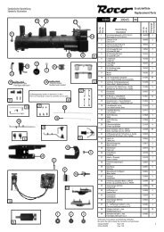
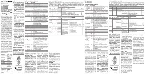
NEM<br />
Einstecken des 6-poligen Steckers<br />
Ankleben des Decoders<br />
CV-WERTE BEIM FLEISCHMANN DCC-DECODER<br />
CV Name Grundwert Bedeutung<br />
1 Primäre Lokadresse 3 Bei DCC wirksam mit CV29 bit 5=0, Wert: 1–127.<br />
2 v min 3 Mindestgeschwindigkeit (Wertebereich: 0-255).<br />
3 Anfahr-Verzögerung 2 Verzögerungswert beim Anfahren.<br />
4 Brems-Verzögerung 2 Verzögerungswert beim Bremsen.<br />
5 v max 180 Maximale Geschwindigkeit (Wertebereich: 2-255).<br />
6 v mid 0 Mittlere Geschwindigkeit (keine Verwendung bei Wert 0, 1) für nichtlineare<br />
Kennlinie.<br />
8 Hersteller ID 155 Lesen: NMRA-Hersteller-Identifikationsnummer. FLEISCHMANN hat<br />
155.<br />
Schreiben: Durch Programmieren dieser CV ist ein Reset einzelner<br />
CVs auf die Werkswerte möglich. Beispiel: CV8 = 3 setzt die CV3 auf<br />
deren Werkswert.<br />
9 Motoransteuerung 20 0: Motorfrequenz 100 Hz, 15...22: Motorfrequenz 15...22 kHz<br />
11 Packet timeout 0 Zeit, nach der eine fahrende Lok ohne weitere Geschwindigkeitsbefehle<br />
gestoppt wird: Zeit = n *0,2s. Bei 0 keine Zeitüberschreitung.<br />
12 Fahrstromart Bit 0=1 Bit 0 = 1: Fahren mit Gleichstrom („analog“) möglich.<br />
Bit 0 = 0: Gleichstrombetrieb aus.<br />
17 Erweiterte Adresse 192 Oberer Anteil der erweiterten Adresse, Wert: 128–9999.<br />
(Oberer Teil) Wird wirksam bei DCC mit CV29 Bit 5=1, Wert: 128–9999.<br />
18 Erweiterte Adresse 0 Unterer Anteil der erweiterten Adresse, Wert: 128–9999.<br />
(Unterer Teil) Wird wirksam bei DCC mit CV29 Bit 5=1, Wert: 128–9999.<br />
29 Konfigurationswerte Bit 0=0 Bit 0: Mit Bit 0=1 wird die Fahrtrichtung des Fahrzeugs umgedreht.<br />
Bit 1=1<br />
Bit 1: Grundwert 1 gilt für Fahrgeräte mit 28/128 Fahrstufen.<br />
Für Fahrgeräte mit 14 Fahrstufen Bit 1=0 einstellen.<br />
Bit 2=1<br />
Fahrstromerkennung: Bit 2=1: Fahren mit Gleichstrom („analog“) möglich.<br />
Bit 2=0: Fahren mit Gleichstrom ausgeschaltet.<br />
Bit 4=0<br />
Umschalten zw. 3-Punkt-Kennlinie Bit4=0 und Fahrstufentabelle<br />
(Bit 4=1) in CV67-94.<br />
Bit 5=0 Bit 5: Zur Verwendung der erweiterten Adresse 128 – 9999 ist Bit 5=1<br />
einzustellen.<br />
30 Fehler-Information 0 Sobald ein Fehler auftritt wird dieser in CV30 gespeichert.<br />
Durch schreiben eines beliebigen Wertes kann die CV30 wieder<br />
gelöscht werden.<br />
Bit 0= 1: Kurzschluss L1 festgestellt<br />
Bit 1= 1: Kurzschluss L2 festgestellt<br />
Bit 6= 1: Kurzschluss Motor festgestellt<br />
Bit 7= 1: Übertemperatur festgestellt<br />
33 Licht vorwärts 1 Zuordnung von interner zu externer Funktion (RP 9.2.2). Out 1: Licht<br />
vorwärts<br />
34 Licht rückwärts 2 Out 2: Licht rückwärts<br />
35 F1 4 Out 3<br />
36 F2 8 Out 4<br />
37 F3 16 Out 5<br />
38 F4 4 Out 6<br />
39 F5 8 Out 7: Acceleration Zero<br />
40 F6 16 Out 8: Half Speed<br />
41 F7 32 Out 9: Train-Navigation (Wichtig: siehe CV63)<br />
42 F8 64 Out 10<br />
43 F9 16 Out 11<br />
44 F10 32 Out 12<br />
45 F11 64 Out 13<br />
46 F12 128 Out 14<br />
51 Individuelle Bit 0=1 Die lastunabhängige Fahrweise (Motorregelung) ist voreingestellt<br />
FLEISCHMANN- (Bit 0=1), kann aber auch ausgeschaltet werden (Bit 0=0).<br />
Einstellungen #1 Bit 6=1 Blinken der Lampen als Fehleranzeige von Kurzschluss, Überhitzung<br />
und Summenstromüberschreibung. Abschaltung der Blinkfunktion<br />
durch Bit 6=0.<br />
64 RESET Das Schreiben einer 1 (CV64=1) setzt den Decoder auf die Werkssiehe<br />
auch<br />
werte zurück. Alle individuell geänderten Einstel lungen gehen verlo-<br />
Reset CV8<br />
ren. Ach tung: Manche Steuergeräte melden bei einem RESET einen<br />
Fehler, führen ihn aber aus, andere nicht. Je nach Steuer gerät hilft<br />
eventuell mehrfaches Ausführen des RESET.<br />
Weitere Reset-Möglichkeiten:<br />
CV64=3: Fahrstufentabelle CVs 67...95, Trimwerte CVs 66, 95;<br />
CV64=4: 3-Punkt-Kennlinie CVs 2, 5, 6, Trimmwerte CVs 66, 95;<br />
CV64=6: Adressen, CVs 1, 17, 18, 29.<br />
66 Vorwärts Trimm 248 Hier sind die Geschwindigkeitswertein CV67-94 vom Grundwert<br />
248=100% prozentual einstellbar, z. B. 124=50%, Wert gilt f. Vor-<br />
wärtsfahrt.<br />
67 Veränderung der In jede der 28 CVs von 67 bis 94 kann ein Geschwindig keitswert zwibis<br />
Regelcharakteristik schen 0 und 255 eingegeben werden. In CV67 kommt die Mindest-,<br />
94 des Steuergeräts in CV94 die Höchst geschwin digkeit. Mit den Zwischenwerten ergeben<br />
diese die Steuerkennlinie. Sie bestimmt, wie sich die Fahrzeug -<br />
geschwindigkeit mit der Reglerstellung ändert.<br />
95 Rückwärts Trimm 248 Wie CV66, jedoch für Rückwärtsfahrt.<br />
105 Benutzervariablen 0 Werte zur freien Verwendung<br />
106 Benutzervariablen 0 Werte zur freien Verwendung<br />
Einstellen der Ausgänge als Lichtausgang bzw. Schaltausgang (Grundeinstellung)<br />
Funktion CV Wert Decoderausgang Beschreibung Einstellungen Teilwert<br />
Lichtausgang /<br />
Schaltausgang<br />
120 0 Out 1: Licht vorwärts, f0v Betriebsart des Decoderausgangs<br />
ist Licht-/<br />
Schaltausgang<br />
0: Ausgang ist Licht-/Schaltausgang<br />
130 0 Out 2: Licht rückwärts, f0r<br />
Analog & DCC<br />
Zuordnung<br />
121 8 Out 1: Licht vorwärts, f0v Helligkeit, Dimmwert des<br />
jeweiligen Ausganges:<br />
Bit 0-3: Das Licht kann in<br />
16 Stufen (0-15) gedimmt<br />
werden.<br />
Parameter für Analog & DCC<br />
Zuordnung: Bit 4-7:<br />
Bit 0: Helligkeit, Dimmwert: 1=ein, 0=aus<br />
Bit 1: Helligkeit, Dimmwert: 1=ein, 0=aus<br />
Bit 2: Helligkeit, Dimmwert: 1=ein, 0=aus<br />
Bit 3: Helligkeit, Dimmwert: 1=ein, 0=aus<br />
Bit 4: Funktion ist ein bei Fahrtrichtung: 0=Vorwärts, 1=Rückwärts<br />
Bit 5: Ausgang ist von der Fahrtrichtung abhängig: 1=ein, 0=aus<br />
Bit 6: Funktion gilt für: 1=DCC und Analog, 0=DCC<br />
Bit 7:Funktion ist aktiv bei: 1=nur bei Fahrt, 0=bei Fahrt und Stillstand<br />
0/1<br />
0/2<br />
0/4<br />
0/8<br />
0/16<br />
0/32<br />
0/64<br />
0/128<br />
131 8 Out 2: Licht rückwärts, f0r<br />
Einstellen der Ausgänge als Lichtausgang bzw. Schaltausgang mit Blinkfunktion<br />
Funktion CV Wert Decoderausgang Beschreibung Einstellungen Teilwert<br />
Lichtausgang /<br />
Schaltausgang<br />
120 1 Out 1: Licht vorwärts, f0v Betriebsart des Decoderausgangs<br />
ist Licht-/Schaltausgang mit Blinkfunktion<br />
1: Ausgang ist Licht-/Schaltausgang mit Blinkfunktion<br />
130 1 Out 2: Licht rückwärts, f0r<br />
Analog & DCC<br />
Zuordnung<br />
121 8 Out 1: Licht vorwärts, f0v Helligkeit, Dimmwert des jeweiligen<br />
Ausganges:<br />
Bit 0-3: Das Licht kann in 16 Stufen<br />
(0-15) gedimmt werden.<br />
Parameter für Analog & DCC Zuordnung:<br />
Bit 4-7:<br />
Bit 0: Helligkeit, Dimmwert: 1=ein, 0=aus<br />
Bit 1: Helligkeit, Dimmwert: 1=ein, 0=aus<br />
Bit 2: Helligkeit, Dimmwert: 1=ein, 0=aus<br />
Bit 3: Helligkeit, Dimmwert: 1=ein, 0=aus<br />
Bit 4: Funktion ist ein bei Fahrtrichtung: 0=Vorwärts, 1=Rückwärts<br />
Bit 5: Ausgang ist von der Fahrtrichtung abhängig: 1=ein, 0=aus<br />
Bit 6: Funktion gilt für: 1=DCC und Analog, 0=DCC<br />
Bit 7: Funktion ist aktiv bei: 1=nur bei Fahrt, 0=bei Fahrt und Stillstand<br />
0/1<br />
0/2<br />
0/4<br />
0/8<br />
0/16<br />
0/32<br />
0/64<br />
0/128<br />
131 8 Out 2: Licht rückwärts, f0r<br />
Blinklicht 122 18 Out 1: Licht vorwärts, f0v Einschaltdauer des Ausgangs bei<br />
Blinkfunktion<br />
1-255: 0,1s-25,5s<br />
0: Licht, Schaltausgang dauernd ein<br />
132 18 Out 2: Licht rückwärts, f0r<br />
123 47 Out 1: Licht vorwärts, f0v Ausschaltdauer des Ausgangs bei<br />
Blinkfunktion<br />
1-255: 0,1s-25,5s<br />
0: Licht, Schaltausgang dauernd ein<br />
133 47 Out 2: Licht rückwärts, f0r<br />
Anzahl der<br />
Blink-/Schaltvorgänge<br />
124 0 Out 1: Licht vorwärts, f0v Anzahl der Blink- / Schaltvorgänge bei<br />
Blinklicht-/ Schaltfunktion. 1-255 Blink-/<br />
Schaltvorgänge werden bei jedem Auslösen<br />
der Funktion am DCC-Steuergerät ausgeführt.<br />
Wenn die Funktion am Steuergerät beendet<br />
wird, wird der Vorgang abgebrochen, wenn<br />
noch nicht alle Blink-/ Schaltvorgänge zeitlich<br />
abgelaufen waren.<br />
1-255: 1-255 Blink-/ Schaltvorgänge<br />
0: Licht, Schaltausgang dauernd blinkend<br />
134 0 Out 2: Licht rückwärts, f0r<br />
DIMMEN UND EINSTELLEN DER LICHTAUSGÄNGE<br />
In den CVs 121 und 131 können umfangreiche Einstellungen für die 2 Lichtausgänge vorgenommen werden. Bei einer Programmierung des<br />
Gesamt-Wertes einer CV (byteweise Programmierung) sind die Teilwerte der entsprechenden Bit-Einstellungen zu addieren und gemeinsam zu<br />
programmieren. Die Ausgänge Out1, Out2 können in folgenden Betriebsarten verwendet werden: 1. Lichtausgang, 2. Lichtausgang mit Blinkfunktion.<br />
Wichtig: Für Out1 und Out2 gilt: Die Auswahl der Fahrtrichtung in CV121, bzw. CV131 Bit4 muss mit der Auswahl des Lichtausganges im<br />
Function mapping CV33 und CV34 übereinstimmen. Anderenfalls heben die beiden Einstellungen sich gegenseitig auf. Der Decoder ist so eingestellt,<br />
das er Fahren mit Analog oder DCC automatisch erkennt. Die Lichtausgänge sind in der Voreinstellung nur bei DCC eingeschaltet. Dies<br />
wurde so gewählt, da im Analogbetrieb die Ausgänge nur dann richtig arbeiten, wenn die daran angeschlossenen LEDs oder Lampen gegen V+<br />
(blaue Litze des Decoders ) und nicht gegen die linke Schiene geschaltet werden.<br />
enclosed iso lating adhesive strip · When<br />
gluing in position, please be careful to<br />
ensure that no exposed parts of the DCC-<br />
DECODER can come into contact with any<br />
metal (cut the adhesive strip to suit).<br />
Please take care when plugging in the<br />
decoder plug into the decoder socket<br />
when it is situated on the motor faceplate,<br />
or around the bogie! It is essential<br />
here to ensure that there can be no short<br />
circuit between the plug and the motor<br />
face-plate/motor/bogie. In order to isolate<br />
the relevant parts, there is a second<br />
adhesive strip included with the decoder.<br />
FITTING THE DCC-DECODER<br />
1. According to the <strong>instructions</strong>, remove the<br />
loco body.<br />
2. Take out the D.C. plug from the 6-pole<br />
digital connector port in the loco (fully<br />
remove the plug so that should an error<br />
occur later, it will be easier to discover<br />
whether the error lies in the loco or in the<br />
DCC-DECODER).<br />
3. Insert the 6-pole plug of the DCC-DECO-<br />
DER into the connector port of the loco.<br />
Please make sure that the marking ”1“<br />
on the plug is on the same edge as the<br />
”1“ on the connector part.<br />
4. With the aid of the included double-sided<br />
adhesive strip, position the DCC-DECO-<br />
DER on the site prepared for it by the loco<br />
manufacturer, or in case none is available,<br />
CV-values of the FLEISCHMANN DCC-DECODER<br />
CV Name Basic value Meaning<br />
1 Loco address 3 On DCC effective with CV29 bit 5=0, value: 1–127.<br />
2 v min 3 Minimum speed (range of values: 0-255)<br />
3 Acceleration rate 2 Inertia Value when Accelerating (range of values: 0-255).<br />
4 Deceleration rate 2 Inertia Value when Braking (range of values: 0-255).<br />
5 v max 180 Maximum speed (range of values: 2-255).<br />
6 v mid 0 Medium speed (not in use when 0) for non-linear characteristic curve.<br />
8 Manufacturer ID 155 NMRA Identification No of Manufacturer. FLEISCHMANN is 155.<br />
If you program values into that CV, you can achieve a reset of certain<br />
CVs to the factory settings. Example: CV8 = 3 will reset CV3 to its<br />
factory setting.<br />
9 Motor control 20 0: motor frequency 100 Hz; 15-22: motor frequency 15-22 kHz<br />
11 Packet timeout 0 Time after which a running loco with missing running <strong>instructions</strong> will<br />
stop: time = n *0,2s. If 0, no timeout.<br />
12 Power source Bit 0=1 Bit 0 = 1: DC operation (”analog“) possible.<br />
conversion<br />
Bit 0 = 0: DC operation off.<br />
17 Extended address 192 Upper section of additional adresses, value: 128–9999.<br />
(Upper section) Effective for DCC with CV29 Bit 5=1, value: 128–9999.<br />
18 Extended address 0 Lower section of additional adresses, value: 128–9999.<br />
(Lower section) Effective for DCC with CV29 Bit 5=1, value: 128–9999.<br />
29 Configuration Bit 0=0 Bit 0: With Bit 0=1 the direction of travel is reversed.<br />
variable Bit 1=1 Bit 1: Basic value 1 valid for controllers with 28/128 speed levels.<br />
For controllers with 14 speed levels use Bit 1=0.<br />
Bit 2=1<br />
Feed current detection: Bit 2=1: DC travel (analog) possible.<br />
Bit 2=0: DC travel off.<br />
Bit 4=0 Switching between 3-point-curve (Bit 4=0) and speed table (Bit 4=1)<br />
in CV67-94.<br />
Bit 5=0 Bit 5: For use of the additional addresses 128 – 9999 set Bit 5=1.<br />
30 Error information 0 If an error occurs, it will be stored in CV30. By writing any value to<br />
CV30 this content can be erased.<br />
Bit 0= 1: Short-circuit on L1 detected<br />
Bit 1= 1: Short-circuit on L2 detected<br />
Bit 6= 1:Short-circuit on Motor detected<br />
Bit 7= 1: Overtemperature detected<br />
33 Light forwards 1 Assignment internal to external function (RP 9.2.2). Out 1: Light forwards<br />
34 Light backwards 2 Out 2: Light backwards<br />
35 F1 4 Out 3<br />
36 F2 8 Out 4<br />
37 F3 16 Out 5<br />
38 F4 4 Out 6<br />
39 F5 8 Out 7: Acceleration Zero<br />
40 F6 16 Out 8: Half Speed<br />
41 F7 32 Out 9: Train-Navigation (Important: see CV63)<br />
42 F8 64 Out 10<br />
43 F9 16 Out 11<br />
44 F10 32 Out 12<br />
45 F11 64 Out 13<br />
46 F12 128 Out 14<br />
51 Individual Bit 0=1 The load independent running (motor control) is preset (Bit 0=1)<br />
FLEISCHMANN- Can be switched off also (Bit 0=0).<br />
settings #1 Bit 6=1 Blinking of lights to indicate short circuit, overheating or current overload.<br />
Switching off this function with Bit 6=0.<br />
64 RESET Writing a 1 (CV64=1) resets the Decoder to the factory settings. All<br />
see also<br />
individual adjustments will le lost. Attention: Some controllers will in-<br />
Reset CV8<br />
dicate an error on RESET, but will carry it out, others will not.<br />
Depending on the respective controller, repeated action of the RESET<br />
will assist.<br />
Further possible resets:<br />
CV64=3: Speed step table CVs 67-95, trim values CVs 66, 95;<br />
CV64=4: 3-point-curve CVs 2, 5, 6, trim values CVs 66, 95;<br />
CV64=6: addresses, CVs 1, 17, 18, 29.<br />
66 Forward trim 248 Here, the speed values contained in CV67-94 can be adjusted by a<br />
percentage from 248=100%. E.g. 124=50%. Value valid for running<br />
forward.<br />
67 Adjustment of A speed between 0 and 255 can be given in each of the 28 CVs from<br />
to control characteristic 67 to 94. CV67 holds the minimum speed, and CV94 holds the top<br />
94 curve of controller speed. The control characteristic curve is then determined by inter<br />
mediate values. They decide how the speed of the vehicle alters with<br />
the controller setting.<br />
95 Backwards trim 248 As CV66, but for running backwards<br />
105 User variables 0 Values free to use<br />
106 User variables 0 Values free to use<br />
then on a metal surface with good heat<br />
conducting capabilities. First of all place<br />
the adhesive strip on the metal surface,<br />
and then carefully place the DCC-DECO-<br />
DER onto the adhesive strip.<br />
5. Replace the loco body, making sure that<br />
the wires are not squeezed.<br />
OPERATION WITH THE<br />
FLEISCHMANN DCC-DIGITAL SYSTEM<br />
Locos with inbuilt DCC-DECODER can be<br />
used with the FLEISCHMANN-controllers<br />
LOK-BOSS, PROFI-BOSS and TWIN-<br />
CENTER 6802 conforming to the NMRA<br />
standard. Which DCC-decoder functions<br />
can be used within which parameters are<br />
fully described in the respective operating<br />
<strong>instructions</strong> of the respective controller.<br />
The prescribed functions shown in the<br />
instruction leaflets included with our controllers<br />
are fully useable with the DCC-<br />
decoder. The simultaneous, compatible<br />
running possibilities with D.C. vehicles on<br />
the same electrical circuit is not possible<br />
with DCC controllers conforming to<br />
NMRA standards (see also manual of the<br />
respective controller).<br />
CODING THE ADDRESS<br />
Using the controller TWIN-CENTER 6802,<br />
multiMAUS and the PROFI-BOSS the<br />
address can be altered at any time from<br />
address 1 to 9999. Using the LOK-BOSS the<br />
address can be altered at any time to<br />
address 1 through 4. Please make yourself<br />
familiar with the <strong>instructions</strong> which are included<br />
with each piece of equipment.<br />
PROGRAMMING WITH DCC<br />
The DCC-decoder enables a range of further<br />
settable possibilities and information according<br />
to its characteristics. This information is<br />
stored in so-called CVs (CV = Configuration<br />
Variable). There are CVs which store only a<br />
single information, the so-called Byte, and<br />
others that contain 8 pieces of information<br />
(Bits). For FLEISCHMANN, the Bits are numbered<br />
from 0 to 7. When programming, you<br />
will need that knowledge. The CVs required<br />
we have listed for you (see CV table).<br />
Programming of the CVs is mainly done with<br />
the TWIN-CENTER, PROFI-BOSS, multi-<br />
MAUS or similar appliances, that are capable<br />
of the programming by bits and bytes in<br />
mode ‘CV direct’. The programming of some<br />
CVs by register-programming is also possible.<br />
Furthermore, all CVs can be programmed<br />
byte-wise on the main track, independently<br />
from the programming-track.<br />
However, this is possible only if your appliance<br />
is capable of this programming-mode<br />
(POM - program on main).<br />
Further information concerning that issue is<br />
given in the respective manuals and operating<br />
<strong>instructions</strong> of the digital controllers.<br />
The pre-adjusted basic values of the CVs can<br />
be altered by use of the TWIN-CENTER,<br />
PROFI-BOSS, multiMAUS and other DCC<br />
controllers that accord to NMRA standards.<br />
The vehicles will then behave according to<br />
the values that you have set within the CVs.<br />
RUNNING ON CONVENTIONAL<br />
DC LAYOUTS<br />
You want to run your FLEISCHMANN DCCloco<br />
once in while on a DC layout? No problem<br />
at all, because as delivered, we have<br />
adjusted the respective CV29 and CV12 in<br />
our decoders so that they can run on ”analog“<br />
layouts as well! However, you may not<br />
be able to enjoy the full range of digital technique<br />
highlights.<br />
SIMULATION OF TRAIN WEIGHT<br />
In our decoders we have integrated acceleration<br />
and braking inertia values, that represent<br />
the weight of a ”real“ locomotive (see CV-table).<br />
Often, however it is of advantage to be<br />
able to switch off this simulation, e.g. when<br />
coupling. The inertia can then be<br />
switched on and off using the function key f5.<br />
SHUNTING GEGAR<br />
Some operational situations require delicate<br />
speed adaption, often called ‘shunting gear’.<br />
By using the f6 function key, you can set your<br />
DCC-loco to ”half speed“ with increased<br />
speed levels in order to make the shunting far<br />
more finely controllable.<br />
ADVICE ON SWITCHING THE DIGITAL<br />
LAYOUT ON AND OFF<br />
To switch off your model railway controller,<br />
first of all activate the emergency stop function<br />
of the controller (see <strong>instructions</strong> with the<br />
controller). Then finally, pull out the mains<br />
plug of the controller power supply; otherwise<br />
you might damage the appliance. If you<br />
ignore this critical advice, damage could be<br />
caused to the equipment.<br />
DIMMING AND ADJUSTMENT OF LIGHT OUTPUTS<br />
In the CVs 121 and 131, you can carry out various adjustments of the light outputs. If you program the total value of a CV (byte-wise programming),<br />
each partial value of the adjusted bit must be added and programmed together. The outputs Out1, Out2 may be used in the following<br />
operation modes: 1. Light output, 2. Light output with blinking function. Important: For Out1 and Out2 each: The selection of the running direction<br />
in CV121, resp. CV131 Bit4 must be identical with the selection of the light output in the function mapping of CV33 and CV34. Otherwise<br />
both adjustments will annulate each other. The decoder is adjusted to automatically detecting analog or DCC operation. The light outputs are<br />
pre-adjusted active only in DCC operation. We made that adjustment, because, in analog operation, the outputs will work correctly only, if the<br />
the connected LEDs or lamps are switched to V+ (blue line of the decoder ) and not against the left-side of the track.<br />
Adjusting the Outputs as Light outputs resp. Switching outputs (Basic setting)<br />
Function CV Value Decoder output Description Settings Part value<br />
Light output<br />
/switching<br />
output<br />
120 0 Out 1: Light forward, f0v Operation mode of decoder<br />
output is light-/ switching<br />
output<br />
0: output is light-/switch-output<br />
130 0 Out 2: Light backward, f0r<br />
Analog & DCC<br />
assignment<br />
121 8 Out 1: Light forward, f0v Brightness, dim value of<br />
resp. output:<br />
Bit 0-3: The light can be<br />
dimmed in 16 steps (0-15)<br />
Parameter for analog & DCC<br />
assignment: Bit 4-7:<br />
Bit 0: Brightness, dim value: 1=on, 0=off<br />
Bit 1: Brightness, dim value: 1=on, 0=off<br />
Bit 2: Brightness, dim value: 1=on, 0=off<br />
Bit 3: Brightness, dim value: 1=on, 0=off<br />
Bit 4: Function is on in direction: 0=forward, 1=backward<br />
Bit 5: Output depends on direction: 1=on, 0=off<br />
Bit 6: Function valid for: 1=DCC and analog, 0=DCC<br />
Bit 7: Function is active at: 1=only when running, 0=running and stand-still<br />
0/1<br />
0/2<br />
0/4<br />
0/8<br />
0/16<br />
0/32<br />
0/64<br />
0/128<br />
131 8 Out 2: Light backward, f0r<br />
Adjusting the Outputs as Light outputs resp. Switching outputs with blinking function<br />
Function CV Value Decoder output Description Settings Part<br />
value<br />
Light output<br />
/switching<br />
output<br />
120 1 Out 1: Light forward, f0v Operation mode of decoder output is<br />
light-/ switching output with blinking<br />
function<br />
1: output is light-/switch-output with blinking function<br />
130 1 Out 2: Light backward, f0r<br />
Analog & DCC<br />
assignment<br />
121 8 Out 1: Light forward, f0v Brightness, dim value of resp. output:<br />
Bit 0-3: The light can be dimmed in 16<br />
steps (0-15)<br />
Parameter for analog & DCC assignment:<br />
Bit 4-7:<br />
Bit 0: Brightness, dim value: 1=on, 0=off<br />
Bit 1: Brightness, dim value: 1=on, 0=off<br />
Bit 2: Brightness, dim value: 1=on, 0=off<br />
Bit 3: Brightness, dim value: 1=on, 0=off<br />
Bit 4: Function is on in direction: 0=forward, 1=backward<br />
Bit 5: Output depends on direction: 1=on, 0=off<br />
Bit 6: Function valid for: 1=DCC and analog, 0=DCC<br />
Bit 7: Function is active at: 1=only when running, 0=running and stand-still<br />
0/1<br />
0/2<br />
0/4<br />
0/8<br />
0/16<br />
0/32<br />
0/64<br />
0/128<br />
131 8 Out 2: Light backward, f0r<br />
Blinking light 122 18 Out 1: Light forward, f0v Switch-on duration of output with<br />
blinking function<br />
1-255: 0,1s-25,5s<br />
0: Light, switch-output permanently on<br />
132 18 Out 2: Light backward, f0r<br />
123 47 Out 1: Light forward, f0v Switch-off duration of output with<br />
blinking function<br />
1-255: 0,1s-25,5s<br />
0: Light, switch-output permanently on<br />
133 47 Out 2: Light backward, f0r<br />
Number of<br />
blink-/switch<br />
cycles<br />
124 0 Out 1: Light forward, f0v Number of blink-/switch-cycles with blinking<br />
light-/switch-function. 1-255 blink-/switch<br />
cycles are carried out with each funktion<br />
transmitted by the DCC controller. If the function<br />
is stopped by the controller, the procedure is<br />
ended, even if there is a rest of cycles.<br />
1-255: 1-255 blink-/ switch cycles<br />
0: Light, switch-output permanently blinking<br />
134 0 Out 2: Light backward, f0r<br />
plug in the 6-pole plug<br />
glue the decoder with adhesive strip
DCC-DECODER 685301<br />
DCC-DECODER 685401<br />
DCC-DECODER 685501<br />
UTILISATION CONFORME<br />
Ce DCC-DÉCODEUR est destiné à être<br />
intégré aux locomotives en modèle réduit<br />
équipées d’un connecteur digital NEM 651.<br />
Toute autre utilisation est interdite.<br />
PROPRIETES DU DÉCODEUR DCC<br />
Le DÉcodeUr DCC peut s’utiliser aussi<br />
bien avec les commandes LOK-BOSS,<br />
PROFI-BOSS, multiMAUS et TWIN-CENTER<br />
6802 qu’avec les commandes DCC au standard<br />
NMRA, sans qu’aucun réglage du DÉcodeUr<br />
DCC du véhicule ne soit nécessaire<br />
en cas de changement d’un système à<br />
l’autre. Equipée d’un DÉcodeUr DCC, la locomotive<br />
est indépendante de la charge,<br />
c’est-à-dire que peu importe si elle monte ou<br />
descend, elle roulera toujours à la même<br />
vitesse (si la puissance du moteur est suffisante).<br />
Dimensions N (max.) : 12,9 x 9 x 3,4 mm ·<br />
Charge ad missible : Moteur 1000 mA, Eclairage<br />
200 mA · Adresse : Encodage électronique<br />
· Fonction spéciale éclairage : Commutable,<br />
éclairage en fonction du sens de la<br />
marche · Régu lation en fonction de la charge :<br />
Vitesse indépendante de la charge · Accélération<br />
et freinage réglables : Réglage sur différents<br />
ni ve aux · Courbe caractéristique de<br />
commande: 2, réglables · Sortie moteur :<br />
Protégée contre les courts- circuits par coupure<br />
de l’alimenta tion · Decodeur : Protégér<br />
contre surchauffage par coupure de<br />
l’alimentation · Fonction d’emetteur de navigation<br />
(TRAIN-NAVIGATION) intégré.<br />
En cas d’un défaut, le DÉcodeUr DCC se<br />
met hors circuit et signale en outre la nature<br />
de la panne en faisant clignoter les ampoules<br />
de la locomotive:<br />
clignotement continu : court-circuit<br />
clignotement double :<br />
clignotement triple :<br />
sur chauffage<br />
sur charge de<br />
courant<br />
Une fois la cause de la panne élimin ée, la<br />
locomotive poursuit sa route.<br />
INDICATION IMPORTANT<br />
Les DÉCODERS DCC digitaux étant des<br />
produits électroniques de pointe, ils doivent<br />
être manipulés avec le plus grand<br />
soin : Tout contact avec un liquide (par ex.<br />
huile, eau, produit nettoyant etc.) compromet<br />
le bon fonctionnement du DÉ-<br />
CODEURS DCC · Toute mani pulation non<br />
conforme avec des objets métalliques<br />
(par ex. tournevis, pincette etc.) peut<br />
endommager le DÉCODEUR DCC sur le<br />
plan mécanique ou électrique · Une manipulation<br />
brutale (par ex. en tirant sur les<br />
fils ou en tordant les composants) peut<br />
endommager l’appareil sur le plan mécanique<br />
ou électrique · Tout travail de<br />
soudage sur le Dècodeur DCC peut le<br />
détériorer.<br />
RISQUE DE COURT CIRCUIT – VEUILLEZ<br />
ABSOLUMENT OBSERVER LES CONSIG-<br />
NES SUIVANTES :<br />
Avant de saisir le DCC-DÉCODEUR, toucher<br />
un objet mis à la terre (par ex. radiateur). · Le<br />
DCC-DÉCODEUR produisant de la chaleur<br />
en fonctionnant, il doit être collé à l’aide du<br />
ruban adhésif (isolant électrique) fourni sur<br />
une surface métallique qui soit la plus<br />
grande possible. · Au collage, veillez à ce<br />
qu’aucune partie du DCC-DÉCODEUR dépassant<br />
des rubans adhésifs n’entre en<br />
contact avec le métal (si nécessaire, recoupez<br />
à longueur le ruban adhésif).<br />
Attention lors du branchement de la<br />
fiche du décodeur dans une prise<br />
d’interface se situant sur le carter du<br />
moteur ! Dans ce cas, veillez absolutement<br />
à éviter tout court circuit entre la<br />
fiche et le carter du moteur/moteur/<br />
châssis. Pour isoler la partie corres-pondante,<br />
le décodeur est fourni avec un<br />
deu xième ruban adhésif.<br />
MONTAGE DU DCC-DÉCODEUR<br />
1. Retirer le boîtier de la locomotive suivant<br />
les <strong>instructions</strong> fournies avec cette dernière.<br />
2. Débrancher la fiche à courant continu du<br />
connecteur digital à 6 pôles de la loco<br />
(bien tirer la fiche). Cela permet par la<br />
suite de détecter en cas d’éventuelles<br />
pannes si le défaut vient de la loco ou du<br />
DCC-DÉCODEUR.<br />
3. Brancher la fiche à 6 pôles du DCC-<br />
DÉCODEUR sur le connecteur existant de<br />
la loco. Ici, veiller à ce que le repère ”1“ de<br />
la fiche soit en regard du repère ”1“ du<br />
connecteur.<br />
4. Coller à l’aide du ruban adhésif double<br />
face fourni le DCC-DÉCODEUR à<br />
l’endroit prévu par le fabricant de la loco<br />
ou, à défaut, sur une surface métallique<br />
dissipant bien la chaleur. Pour cela, coller<br />
d’abord l’adhésif sur la surface métallique<br />
avant d’y disposer soigneusement le<br />
DCC-DÉCO DEUR.<br />
5. Remonter le boîtier de la loco en veillant à<br />
ne pas coincer les fils.<br />
FONCTIONNEMENT AVEC LES<br />
SYSTE MES FLEISCHMANN DCC-DIGITAL:<br />
Le DÉCODEUR DCC fonctionne avec toutes<br />
les commandes centrale LOK-BOSS,<br />
PROFI-BOSS, multiMAUS et TWIN-CEN-<br />
TER 6802. Les fonctions décrites dans les<br />
<strong>instructions</strong> de service de ces commandes<br />
sont toutes exploitables avec le Dècodeur<br />
DCC. Avec les centrales de commande<br />
DCC normalisées NMRA, le<br />
système lui-même n'autorise pas la traction<br />
simultanée compatible de plusieurs<br />
véhicules à courant continu sur le même<br />
tronçon de voie (voir <strong>instructions</strong> de service<br />
de la commande en question).<br />
ENCODAGE DE L’ADRESSE<br />
Avec le commande TWIN-CENTER 6802,<br />
multiMAUS et PROFI-BOSS 686601,<br />
l’adresse peut être modifiée à tout moment<br />
sur un chiffre compris entre 1 et 9999. Avec<br />
le commande LOK-BOSS, l’adresse peut<br />
être modifiée à tout moment sur un chiffre<br />
compris entre 1 et 4. Pour cette opération,<br />
veuillez vous reporter aux <strong>instructions</strong> de<br />
service fournies avec la commande en question.<br />
PROGRAMMATION DCC<br />
Le DÉCODEUR DCC dispose d’une série de<br />
possibilités de réglages et d’informations<br />
supplémentaires qui déterminent son comportement<br />
ou qui permettent d’en tirer des<br />
conclusions. Ces informations sont ou sont<br />
appelées à être mémori sées dans des dénommées<br />
CV (Configuration Variable). Il y a<br />
des CV qui ne mémorisent qu’une seule information<br />
(octet) comme il y en a d’autres<br />
qui en contiennent 8. Ces informations sont<br />
stockées dans des dé nommés Bits. Ces<br />
Bits sont numérotés par FLEISCHMANN de<br />
0 à 7.<br />
La programmation des CV est fait principalement<br />
avec le TWIN-CENTER, PROFI-BOSS,<br />
multiMAUS ou les appareils similaires, cela<br />
est capable de la programmation en mode<br />
‘CV direct’ en Bits et en octets. La programmation<br />
de quelques CV par la registre-programmation<br />
est aussi possible. De plus, tous<br />
les CV peuvent être programmés par octets<br />
sur la piste principale, d'une manière indépendante<br />
de la piste à programmation. Cependant,<br />
ceci est possible seulement si<br />
votre appareil est capable de ce mode de<br />
programmation POM (‘Program on main’).<br />
Pour la programmation, il vous faut ces<br />
renseignements. Nous vous avons listé les<br />
CV nécessaires. Plusieurs information voir<br />
les manuels et les <strong>instructions</strong> de service au<br />
commandes numeriques. Les valeurs assignées<br />
aux CV peuvent être reprogrammées<br />
avec le TWIN-CENTER 6802, multiMAUS et<br />
PROFI-BOSS 686601 et d’autres commandes<br />
DCC normalisées NMRA. Ensuite, les<br />
véhicules se comportent suivant les nouveaux<br />
paramètres des CV modifiés.<br />
TRACTION EN COURANT CONTINU<br />
Vous souhaitez tracter une fois votre loco<br />
FLEISCHMANN DIGITAL sur un réseau à<br />
courant continu ? Pas de problème : à la<br />
livraison, les variables des CV29 et CV12<br />
sont réglées de sorte à permettre à nos<br />
décodeurs DCC de fonctionner aussi sur<br />
des réseaux ”analogiques“ à courant continu.<br />
Bien entendu, vous ne pourrez alors<br />
pas profiter de tous les avantages de la<br />
technique digitale.<br />
SIMULATION DE L’INERTIE<br />
Nous avons préprogrammé nos locos<br />
digitales avec des valeurs de retard à<br />
l’accélération et au freinage simulant l'inertie<br />
d'une ”véritable“ loco (voir tableau). Souvent,<br />
vous verrez qu’il est avantageux de<br />
pouvoir neutraliser cette simulation, par ex.<br />
pour atteler des véhicules. La touche de<br />
fonction f5 vous permet ensuite d’activer et<br />
de désactiver l’accélération/le freinage de la<br />
loco.<br />
VITESSE DE TRIAGE<br />
Certaines situations de conduite exigent un<br />
ajustement en finesse de la vitesse avec la<br />
dénommée vitesse de triage. La touche de<br />
fonction f6 vous permet de faire passer<br />
votre loco DCC à la ”vitesse lente“ et de<br />
pouvoir réaliser des opérations de triage<br />
avec la même plage de réglage, mais plus<br />
fine de la vitesse.<br />
CONSIGNES POUR METTRE<br />
L’INSTALLATION DIGITAL HORS CIRCUIT<br />
Avant d’éteindre l’installation, activer la fonction<br />
d’arrêt d’urgence de la commande (se<br />
référer pour cela aux <strong>instructions</strong> de service<br />
de la commande). Débrancher ensuite la<br />
prise secteur du transfo. La non-observation<br />
de cet avertissement de danger peut entraîner<br />
la détérioration de l'appareil.<br />
Valeurs CV de DÉCODEUR DCC FLEISCHMANN<br />
CV Nom Valeur de base Description<br />
1 Adresse loco (prim.) 3 Activée sur DCC avec CV29 bit 5=0, valeur : 1–127:<br />
2 v min 3 Vitesse minimale (domaine des valeurs : 0-255).<br />
3 Retard à l’accélération 2 Valeur de retard d’accélération (domaine des valeurs : 0-255).<br />
4 Retard au freinage 2 Valeur de retard de freinage (domaine des valeurs : 0-255).<br />
5 v max 180 Vitesse maximale (domaine des valeurs : 2-255).<br />
6 v mid 0 Vitesse moyen (aucun emploi par valeur 0) pour caractéristique nonlinéaire.<br />
8 ID du fabricant 155 Lire : <strong>Fleischmann</strong> ID, attribué par NMRA. Ècrire : RESET des CVs<br />
individuelles aux valeurs usine, p ex. : CV8=3 repose CV3 sur la<br />
valeur usine.<br />
9 Pilotage moteur 20 0: PWM off, resp. frequence moteur 100 Hz, 15-22 : frequence mot.<br />
15-22 kHz<br />
11 Packet timeout 0 Temps, après une loco roulant est arrêtée sans des <strong>instructions</strong> de<br />
marche :<br />
Temps = n *0,2s. Si 0 pas de timeout.<br />
12 Type de courant Bit 0=1 Quel est le protocole active en plus de DCC :<br />
Bit 0 : Analogue 1=on, 0=off Bit 1...4 : toujour 0 Bit 5 : FMZ, touj. 0<br />
Bit 6...7 : toujour 0<br />
17 Adresse longue 192 Partie supérieure de l’adresse étendue, valeur : 128–9999.<br />
(partie supérieure) Est activée sur DCC avec CV29 Bit 5=1, valeur : 128–9999.<br />
18 Adresse longue 0 Partie inférieure de l’adresse étendue, valeur : 128–9999.<br />
(partie inférieur) Est activée sur DCC avec CV29 Bit 5=1, valeur : 128–9999.<br />
29 Valeurs de Bit 0=0 Bit 0: avec Bit 0=1, inversion du sens de la marche du véhicule.<br />
configuration #1 Bit 1=1 Bit 1: la valeur par défaut 1 s’applique aux véhicules à 28/128 niveaux<br />
de conduite.<br />
Pour les véhicules à 14 niveaux de conduite, régler sur Bit 1=0.<br />
Bit 2=1 Caractéristique du courant de traction : Bit 2=1: traction en courant<br />
continu (”analogique“) possible. Bit 2=0 : traction en courant continu<br />
désactivée.<br />
Bit 4=0 Choisir la caract. à 3 points (Bit 4=0) ou tableau de vit. (Bit 4=1) entre<br />
les CV67-94.<br />
Bit 5=0 Bit 5 : pour utiliser l’adresse étendu 128 – 9999 régler sur Bit 5=1.<br />
30 Information d’erreur 0 Si un erreur existe, il est sauvé entre CV30. Par ècrire d'un valeur<br />
quelconque la CV30 peut être supprimé.<br />
Bit 0= 1 : Court-circuit L1 (Out 1) trouvé<br />
Bit 1= 1 : Court-circuit L2 (Out 2) trouvé<br />
Bit 6= 1 : Court-circuit moteur trouvé<br />
Bit 7: 1 : Surchauffage trouvé<br />
33 Feu avant 1 Matrice pour afectation de fonction interne à externe (RP 9.2.2).<br />
Out 1 : Feu avant<br />
34 Feu arrière 2 Out 2 : Feu arrière<br />
35 F1 4 Out 3 :<br />
36 F2 8 Out 4 :<br />
37 F3 16 Out 5 :<br />
38 F4 4 Out 6 :<br />
39 F5 8 Out 7 : accélération zero<br />
40 F6 16 Out 8 : demi vitesse<br />
41 F7 32 Out 9 : Train-Navigation (important : voir CV 63)<br />
42 F8 64 Out 10 :<br />
43 F9 16 Out 11 :<br />
44 F10 32 Out 12 :<br />
45 F11 64 Out 13 :<br />
46 F12 128 Out 14 :<br />
51 Fonctions Bit 0=1 Le traction indépendante de la charge (régulation moteur) est préré-<br />
FLEISCHMANN<br />
glée (Bit 0=1), cette fonction pouvant cependant être désactivée<br />
individuelles #1 (Bit 0=0).<br />
Bit 6=1 Clignotement des ampoules signalant une panne court-circuit,<br />
surchauffage ou surcharge de courant. Annulation de la fonction de<br />
clignotement avec Bit 6=0.<br />
64 RESET 0 Ne peut pas être modifiée. La saisie d’un 1 (CV64=1) restaure les vavoir<br />
aussi<br />
leurs par défaut du décodeur. Tous les réglages personnalisés sont perdus.<br />
Reset CV8<br />
Attention : certaines commandes signalent une panne pendant le<br />
RESET tout en exécutant ce dernier, d’autres non. Selon la commande,<br />
il sera éventuellement utile d’effectuer le RESET à plusieurs<br />
reprises. Autres possibilités RESET :<br />
CV64=3: Tableau des niveaux de conduite CV 67-94, valeurs<br />
d’adaptation de la vitesse CV 66, 95; CV64=4: Courbe caractéristique<br />
à 3 points CV 2, 5, 6, valeurs d’adaptation de la vitesse CV 66,<br />
95; CV64=6: adresses, CVs 1, 17, 18, 29.<br />
66 Adaptation de la 248 Ici, les valeurs des vitesses peuventt être modifieés par CV67-94 en<br />
vitesse avant<br />
pourcentage de valeur de base 248=100% a , p. ex. 124=50%, valeur<br />
être valable p. marche avant.<br />
67 Modification de la Chaqune des 28 CV de 67 à 94 autorise l’entrée d’une vitesse comprise<br />
à caractéristique de entre 0 et 255.<br />
94 commande (courbe La CV67 reçoit la vitesse minimum, la CV94 la vitesse maximale. Assocaractéristique)<br />
ciées aux valeurs de reglage de la intermédiaires, ces vitesses constituent<br />
la courbe caractéristique de commande.<br />
Celle-ci détermine la manière dont change la vitesse du véhicule en<br />
fonction de la position du régleur.<br />
95 Ajustage marcher arr. 248 Comme CV66, mais pour la marche arrière.<br />
105 Variables client 0 Valeurs pour une utilisation libre<br />
106 Variables client 0 Valeurs pour une utilisation libre<br />
Brancher la fiche à 6 pôles<br />
Coller le decodeur<br />
Table d'ajustements de base aux sorties (outputs) utilisés à sorties lumineuses ou sorties à commutation :<br />
Ajustement des sorties aux sorties lumières ou sorties à commutation (ajustement de base)<br />
Fonction CV Valeur Sortie décodeur Description Ajustements Val. partial<br />
Sortie lumineuse/Sortie<br />
à<br />
commutation<br />
Affectation<br />
analogue et<br />
DCC<br />
120 0 Out 1 : feu avant, f0v Mode d'operation du 0 :Sortie est Sortie lumineuse/Sortie à commutation<br />
décodeur est Sortie lumineuse/Sortie<br />
130 0 Out 2 : feu arrière, f0r<br />
à commutation<br />
121<br />
131<br />
8<br />
8<br />
Out 1 : feu avant, f0v<br />
Out 2 : feu arrière, f0r<br />
Luminosité, valeur baissée<br />
par sortie: Bit 0-3: La<br />
luminosité peut être ajustée<br />
par 16 niveaux (0-15)<br />
Paramètre pour affectation<br />
analogue & DCC : Bit 4-7:<br />
Bit 0: Luminosité, valeur baissée : 1=on, 0=off<br />
Bit 1: Luminosité, valeur baissée : 1=on, 0=off<br />
Bit 2: Luminosité, valeur baissée : 1=on, 0=off<br />
Bit 3: Luminosité, valeur baissée : 1=on, 0=off<br />
Bit 4: Fonction active en marche : 0=avant, 1=arrière<br />
Bit 5: Sortie dépend de la direction de conduite : 1=on, 0=off<br />
Bit 6: Fonction valable pour : 1=DCC et analogue, 0=DCC<br />
Bit 7: Fonction active en : 1=marche seulement, 0=en marche et à l'arrêt<br />
Ajustement des sorties aux sorties lumières ou sorties à commutation avec fonction clignotant<br />
Fonction CV Valeur Sortie décodeur Description Ajustements Val. partial<br />
Sortie lumière/<br />
Sortie à<br />
commutation<br />
Affectation<br />
analogue et<br />
DCC<br />
Lumière<br />
clignotant<br />
Nombre<br />
des cycles<br />
clignotement/<br />
cycles de<br />
commutation<br />
120 1 Out 1 : feu avant, f0v Mode d'operation du décodeur est Sortie<br />
lumière/Sortie à commutation avec<br />
130 1 Out 2 : feu arrière, f0r fonction clignotant<br />
121<br />
131<br />
8<br />
8<br />
Out 1 : feu avant, f0v<br />
Out 2 : feu arrière, f0r<br />
Luminosité, valeur baissée par sortie:<br />
Bit 0-3: La luminosité peut être ajustée<br />
par 16 niveaux (0-15)<br />
Paramètre pour affectation analogue &<br />
DCC : Bit 4-7:<br />
122 18 Out 1 : feu avant, f0v Durée switch-on de la sortie en fonction<br />
de clignotement.<br />
132 18 Out 2 : feu arrière, f0r<br />
123 47 Out 1 : feu avant, f0v Durée switch-off de la sortie en fonction<br />
de clignotement.<br />
133 47 Out 2 : feu arrière, f0r<br />
124<br />
134<br />
0<br />
0<br />
Out 1 : feu avant, f0v<br />
Out 2 : feu arrière, f0r<br />
Nombre de cycles clignotants/commutations<br />
enfonction de sortie clig./comm.<br />
1..255 cycles clig./comm. sont exécutés<br />
à chaque déclenchement de la fonction<br />
au niveau du centrale DCC. Si la fonction<br />
est résilié à la centrale, l'opération est<br />
annulée même si tous les cycles clig./<br />
comm. n'étaient pas encore finis.<br />
1: Sortie est Sortie lumineuse/Sortie à commutation avec fonction<br />
clignotant<br />
Bit 0: Luminosité, valeur baissée : 1=on, 0=off<br />
Bit 1: Luminosité, valeur baissée : 1=on, 0=off<br />
Bit 2: Luminosité, valeur baissée : 1=on, 0=off<br />
Bit 3: Luminosité, valeur baissée : 1=on, 0=off<br />
Bit 4: Fonction active en marche : 0=avant, 1=arrière<br />
Bit 5: Sortie dépend de la direction de conduite : 1=on, 0=off<br />
Bit 6: Fonction valable pour : 1=DCC et analogue, 0=DCC<br />
Bit 7: Fonction active en : 1=marche seulement, 0=en marche et à l'arrêt<br />
1-255: 0,1s-25,5s<br />
0: Lumière, sortie de commutation en permanence<br />
1-255: 0,1s-25,5s<br />
0: Lumière, sortie de commutation en permanence<br />
1-255: 1-255 cycles de clignotement/cycles de commutation<br />
0: Lumière, sortie de commutation clignoté en permanence<br />
AJUSTEMENTS DES SORTIES DE FEU<br />
Dans les CV 121 et 131, (voir Table d'ajustements de base aux sorties (outputs) utilisés à sorties lumineuses ou sorties à commutation)<br />
vous pouvez exécuter de divers ajustements aux le deux sorties d’illumination. Si vous programmez la valeur totale d'un CV (en programmation<br />
par octets), chaque valeur partielle du bit ajusté doit être ajoutée et doit être programmée ensemble. Les sorties Out1, Out2 peuvent être utilisés<br />
dans les modes suivants : 1. Sortie lumière, 2. Sortie lumière clignotant. Important : Pour Out1 et Out2 est valable: Le choix de la direction en<br />
CV121, CV131 Bit 4 doit correspondre avec la sélection de sortie lumière dans les CV33 et CV34 («function mapping»). Sinon, les deux réglages<br />
s'annulent. Le décodeur peut reconnaître la conduite analogique ou DCC automatiquement. Les sorties de la lumière peuvent être allumés par<br />
défaut uniquement pour l'operation DCC. Cela a été choisi de manière, que les sorties analogiques à travailler correctement, seulement si les<br />
lampes ou LED's seront connectés à V + (fil bleu du décodeur) et ne pas sont connectées sur le rail de gauche.<br />
0/1,<br />
0/2,<br />
0/4,<br />
0/8<br />
0/16,<br />
0/32<br />
0/64<br />
0/128<br />
0/1,<br />
0/2,<br />
0/4,<br />
0/8<br />
0/16,<br />
0/32<br />
0/64<br />
0/128