Z 107900 - Hasco
Z 107900 - Hasco
Z 107900 - Hasco

Create successful ePaper yourself
Turn your PDF publications into a flip-book with our unique Google optimized e-Paper software.
NEU!<br />
NEW NOUVEAU<br />
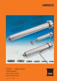
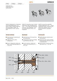
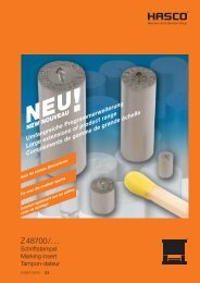
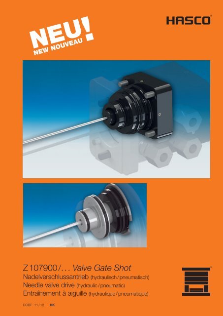
Z<strong>107900</strong> /. . . Valve Gate Shot<br />
Nadelverschlussantrieb (hydraulisch / pneumatisch)<br />
Needle valve drive (hydraulic / pneumatic)<br />
Entraînement à aiguille (hydraulique / pneumatique)<br />
DGBF 11 / 12<br />
HK
hydraulisch<br />
hydraulic<br />
hydraulique<br />
pneumatisch<br />
pneumatic<br />
pneumatique<br />
Z <strong>107900</strong> /. . .<br />
Z 107920 /. . . Z 107910 /. . .<br />
Das neue HASCO Nadelverschlussprogramm<br />
kombiniert die langjährige<br />
Erfahrung im Nadelventilbereich mit<br />
neuester Dichtungstechnik und<br />
zuverlässigem Verstellmechanismus.<br />
The new HASCO needle valve range<br />
combines the many years of HASCO<br />
experience in the field of needle valve<br />
technology with the latest sealing<br />
developments and a reliable adjusting<br />
mechanism.<br />
La nouvelle gamme d'obturateurs à<br />
aiguille HASCO combine la longue<br />
expérience de HASCO dans la<br />
technique des obturateurs avec les<br />
dernières innovations en matière<br />
d'étanchéité et un mécanisme<br />
de réglage fiable.<br />
Besondere Merkmale<br />
Servicefreundliche Bedienung mit<br />
geringem Wartungsaufwand<br />
Einfacher Ein- / Ausbau der<br />
Ventilnadeln<br />
Von außen separat einstellbare<br />
Nadelposition<br />
Neue Distanzscheiben, hochpräzise<br />
Nadelführungen und Ventilnadeln<br />
Saubere Bedingungen<br />
Modular aufgebautes System<br />
Kompakte Bauweise<br />
Vereinfacht die Konstruktion<br />
Features<br />
Service-friendly operation with little<br />
maintenance required<br />
Easy assembly / dismantling of the<br />
valve needles<br />
Needle position can be separately<br />
adjusted from the outside<br />
New spacer disks, high-precision<br />
needle guides and valve needles<br />
Clean conditions<br />
Modular system<br />
Compact design<br />
Simplifies design<br />
Caractéristiques particulières<br />
Simplicité d'entretien avec coûts<br />
de maintenance faibles<br />
Montage/Démontage aisé des<br />
aiguilles d'obturation<br />
Position des aiguilles réglable<br />
individuellement depuis l'extérieur<br />
Nouvelles rondelles d'entretoise,<br />
aiguilles et guidages d'aiguille<br />
haute précision<br />
Conditions de propreté<br />
Système de construction modulaire<br />
Construction compacte<br />
Simplifie la conception<br />
Z <strong>107900</strong> /. . . , Z 107920 /. . .<br />
Hydraulisch<br />
Zur Demontage der Nadel ist keine<br />
Öffnung des Hydrauliksystems<br />
erforderlich<br />
Als Einbau- und als Flanschversion<br />
in drei Größen verfügbar<br />
Variable Einbaumöglichkeiten<br />
Z <strong>107900</strong> /. . . , Z 107920 /. . .<br />
Hydraulic<br />
To dismount the needle, there is no<br />
need to open the hydraulic system<br />
Available in three sizes as an<br />
integrated or flange version<br />
Variable installation possibilities<br />
Z <strong>107900</strong> /. . . , Z 107920 /. . .<br />
Hydraulique<br />
Il n'est pas nécessaire d'ouvrir<br />
le système hydraulique pour<br />
démonter les aiguilles<br />
Disponible en version encastrée<br />
et en version à bride, en trois<br />
dimensions<br />
Différentes possibilités de montage<br />
Z 107910 /. . .<br />
Pneumatisch<br />
Kolben ist feststellbar, falls einzelne<br />
Kavitäten beschädigt sind<br />
Vier Baugrößen mit variablem<br />
Nadelhub lieferbar<br />
Z 107910 /. . .<br />
Pneumatic<br />
Plunger can be fixed if individual<br />
cavities are damaged<br />
Four model sizes with variable<br />
needle stroke are available<br />
Z 107910 /. . .<br />
Pneumatique<br />
En cas d’endommagement de<br />
cavités individuelles le piston<br />
peut être fixé<br />
Quatre dimensions avec différentes<br />
courses d'aiguilles<br />
2
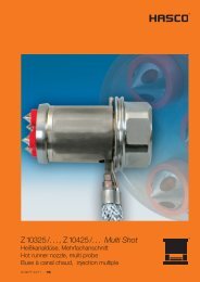
Nadelhalter<br />
Needle holder<br />
Porte-aiguille<br />
Nadelmontage<br />
Jede Antriebseinheit ist mit einem<br />
speziellen Verstellmechanismus der<br />
Ventilnadel ausgestattet, welcher<br />
auch den Mittenversatz durch<br />
Wärmeausdehnung ausgleicht.<br />
Die zudem sehr einfache Nadel -<br />
montage und -demontage erfolgt von<br />
außen über die Aufspannplatte.<br />
Der Antrieb bleibt hierbei geschlossen,<br />
sodass eine Verschmutzung z.B. durch<br />
austretendes Hydrauliköl vermieden<br />
wird.<br />
Die Feineinstellung der Nadelposition<br />
erfolgt im aufgewärmten Zustand<br />
mittels drehbarem Nadelhalter.<br />
Hierbei entspricht die Skalierung eines<br />
Teilstrichs einer axialen Verstellung von<br />
0,06 mm.<br />
Needle mounting<br />
Every drive unit is provided with a<br />
special adjusting mechanism of the<br />
valve needle to balance out the<br />
centre misalignment through<br />
thermal expansion as well.<br />
Mounting and removal of the needle<br />
are very easy as the work can be<br />
carried out from outside via the platen.<br />
The drive unit remains closed to avoid<br />
contamination e.g. through leaking<br />
hydaulic oil.<br />
The fine adjustment of the needle<br />
position should be made when warm<br />
using a twistable needle holder.<br />
One division on the scale line is<br />
equivalent to an axial adjustment<br />
of 0.06 mm.<br />
Montage de l’aiguille<br />
Chaque unité d’entraînement est<br />
équipée d'un mécanisme de réglage<br />
spécifique d’aiguille qui compense<br />
aussi le chevauchement induit par<br />
la dilatation thermique.<br />
Le montage et démontage des aiguilles,<br />
très aisé, s'effectue depuis l'extérieur,<br />
sur la plaque de fixation.<br />
L’entraînement reste fermé pendant ce<br />
temps, pour évitement d’encrassement<br />
p.ex. dû à l’écoulement de huile<br />
hydraulique.<br />
La position précise de l'aiguille est<br />
obtenue à l'état chauffé à l'aide du<br />
support indexé.<br />
Dans ce cas, l'échelle de la course<br />
axiale correspond en partie à un<br />
décalage de 0.06 mm.<br />
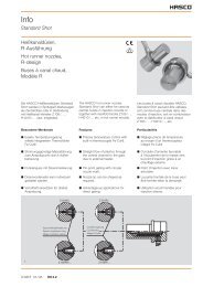
Ein-/ Ausbau der Ventilnadel<br />
Assembly / dismantling of the<br />
needle valve<br />
Montage / Démontage de l’aiguille<br />
d’obturation<br />
2<br />
1<br />
Mittels Schraubendreher den Nadelhalter (1) ausschrauben<br />
und den Keil (2) ausbauen. Anschließend kann die Nadel<br />
entfernt werden. Die Montage erfolgt in umgekehrter<br />
Reihenfolge.<br />
Using a screw driver, unscrew the needle holder (1) and<br />
dismantle the wedge (2). The needle can then be removed.<br />
Assembly takes place in reverse order.<br />
Dévisser le porte-aiguille (1) à l’aide d’un tournevis et<br />
démonter la clavette (2). L’aiguille peut ensuite être retirée.<br />
Le montage s’effectue en repectant la chronologie inverse.<br />
3
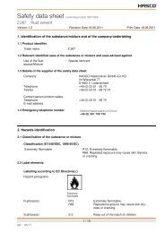
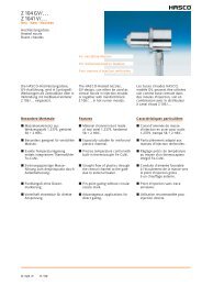
Z <strong>107900</strong> /. . .<br />
Hydraulisch · Hydraulic · Hydraulique<br />
Einbaubeispiel<br />
Mounting example<br />
Exemple de montage<br />
Einbauhinweise Mounting instructions Instructions de montage<br />
H106/..., H10600/... H4010/.../S,<br />
H4015/..., H4510/...<br />
10 8,5<br />
z.B. /e.g. /p.ex.<br />
Z3340/...<br />
Z20214/...<br />
Z107930/...<br />
Z107931/...<br />
Nadel öffnen<br />
open needle<br />
ouvrir l’aiguille<br />
Nadel schließen<br />
close needle<br />
fermer l’aiguille<br />
Öl<br />
Öl<br />
oil<br />
huille<br />
Um eine dauerhaft einwandfreie<br />
Funktion und Dichtigkeit des<br />
Hydraulikzylinders zu gewährleisten<br />
sind die Ölleitungen sehr sorgfältig<br />
zu reinigen, damit keine Späne,<br />
Grate, Schmutz und Fremdpartikel<br />
mit dem Öl in den Hydraulikzylinder<br />
gelangen.<br />
Dichtungen und Bauteile vor den<br />
Einbau sollen eingefettet oder eingeölt<br />
werden.<br />
Keine Schmierstoffe mit Feststoffzusätzen,<br />
wie Molybdändisulfid<br />
oder Zinksulfid verwenden.<br />
To ensure continuous perfect function<br />
and tightness of the hydraulic cylinder,<br />
the oil lines must be cleaned very<br />
carefully so that no filings, burrs, dirt<br />
or foreign bodies get into the hydraulic<br />
cylinder along with the oil.<br />
Seals and components should be<br />
lubricated or oiled before they are<br />
installed.<br />
Do not use lubricants with solid additives<br />
such as such as molybdenum<br />
disulphide or zinc sulphide.<br />
Pour garantir le fonctionnement durablement<br />
irréprochable et l’étanchéité<br />
du vérin hydraulique, les canalisations<br />
d’huile doivent être nettoyées très<br />
soigneusement afin d’éviter que des<br />
copeaux, bavures, salissures et<br />
particules extérieures n’accèdent<br />
au vérin hydraulique via l'huile.<br />
Les joints et les pièces doivent être<br />
graissés ou huilés avant le montage.<br />
Ne pas utiliser de lubrifiants contenants<br />
des additifs solides tels que le bisulfure<br />
de molybdène ou le sulfure de zinc.<br />
4
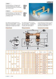
Z <strong>107900</strong> /. . .<br />
Z <strong>107900</strong> / …<br />
Hydrauliknadelventil<br />
Hydraulic needle valve<br />
Obturateur hydraulique<br />
T max.: 150 °C<br />
P max.: 50 bar<br />
Hydraulisch · Hydraulic · Hydraulique<br />
Ø 2; Ø 2,5<br />
(Ventilnadel)<br />
(Valve needle)<br />
(Aiguille de soupape)<br />
56<br />
8,5<br />
12,2<br />
0,5<br />
F2 F1<br />
63,8<br />
9<br />
Z31/6x22<br />
6<br />
Z107931/... 56 -0,1<br />
6<br />
Z107930/...<br />
6<br />
28 g6<br />
d2<br />
48 g6<br />
1<br />
H1<br />
d1<br />
46 g6<br />
42<br />
56 -0,1<br />
Z1004/...<br />
19,3<br />
25,3<br />
37,8<br />
20,2<br />
R7<br />
42<br />
45,3<br />
l1<br />
Axiale Nadelverstellung / Needle adjustment in axial direction / Réglage axial de l’aiguille:<br />
Radialer Mittenversatz / Radial eccentricity / Chevauchement radial:<br />
Nestabstand / Cavity centre-to-centre distance / Escart de grappe:<br />
± 1 mm<br />
0,75 mm / [Seite / side / côté]<br />
min. 56 mm<br />
Z 107931/. . . Z 107930 /. . . F1 / F2 [N] (30 bar) d2 d1 H1 l1 Nr. / No.<br />
. . .31 x 10 x 10 . . .2 x 10 x 21 1960 2 34 4 300 Z <strong>107900</strong> / 2 x 34 x 4 x 300<br />
. . .2,5 x 10 x 21 2,5 2,5<br />
. . .2 x 10 x 21 2 8 2 x 34 x 8 x 300<br />
. . .2,5 x 10 x 21 2,5 2,5<br />
5
R7<br />
Z <strong>107900</strong> /. . .<br />
Z <strong>107900</strong> / …<br />
Hydrauliknadelventil<br />
Hydraulic needle valve<br />
Obturateur hydraulique<br />
T max.: 150 °C<br />
P max.: 50 bar<br />
Hydraulisch · Hydraulic · Hydraulique<br />
Ø 3; Ø 4<br />
(Ventilnadel)<br />
(Valve needle)<br />
(Aiguille de soupape)<br />
56 8,5<br />
12,2<br />
0,5<br />
F2 F1<br />
63,8<br />
9<br />
Z31/6x22<br />
6<br />
Z107931/...<br />
6 6<br />
62 -0,1<br />
Z107930/...<br />
34 g6<br />
d2<br />
52 g6<br />
54 g6<br />
1<br />
H1<br />
d1<br />
48<br />
62 -0,1<br />
Z1004/...<br />
5,3<br />
19,3<br />
25,3<br />
37,8<br />
20,2<br />
48<br />
45,2<br />
l1<br />
Axiale Nadelverstellung / Needle adjustment in axial direction / Réglage axial de l’aiguille:<br />
Radialer Mittenversatz / Radial eccentricity / Chevauchement radial:<br />
Nestabstand / Cavity centre-to-centre distance / Escart de grappe:<br />
± 1 mm<br />
1 mm / [Seite / side / côté]<br />
min. 62 mm<br />
Z 107931/. . . Z 107930 /. . . F1 / F2 [N] (30 bar) d2 d1 H1 l1 Nr. / No.<br />
. . .31 x 10 x 10 . . .3 x 10 x 21 2630 3 40 4 400 Z <strong>107900</strong> / 3 x 40 x 4 x 400<br />
. . .4 x 10 x 21 4 4<br />
. . .3 x 10 x 21 3 8 3 x 40 x 8 x400<br />
. . .4 x 10 x 21 4 4<br />
6
Z <strong>107900</strong> /. . .<br />
Z <strong>107900</strong> / …<br />
Hydrauliknadelventil<br />
Hydraulic needle valve<br />
Obturateur hydraulique<br />
T max.: 150 °C<br />
P max.: 50 bar<br />
Hydraulisch · Hydraulic · Hydraulique<br />
Ø 6<br />
(Ventilnadel)<br />
(Valve needle)<br />
(Aiguille de soupape)<br />
76<br />
8,5<br />
18<br />
0,5<br />
F2 F1<br />
13<br />
Z31/8x30<br />
Z107931/...<br />
Z107930/...<br />
38<br />
6<br />
6<br />
8<br />
80 -0,1<br />
H1<br />
d2<br />
1<br />
d1<br />
d1<br />
61<br />
71 g6<br />
69 g6<br />
54 g6<br />
80 -0,1<br />
Z1004/...<br />
21,2<br />
40,5<br />
26<br />
R7<br />
73,7<br />
58,6<br />
l1<br />
Axiale Nadelverstellung / Needle adjustment in axial direction / Réglage axial de l’aiguille:<br />
Radialer Mittenversatz / Radial eccentricity / Chevauchement radial:<br />
Nestabstand / Cavity centre-to-centre distance / Escart de grappe:<br />
± 1 mm<br />
1,5 mm / [Seite / side / côté]<br />
min. 80 mm<br />
Z 107931/. . . Z 107930 /. . . F1 / F2 [N] (30 bar) d2 d1 H1 l1 Nr. / No.<br />
. . .40 x 12 x 10 . . .6 x 12 x 21 5280 6 55 6 450 Z <strong>107900</strong> / 6 x 55 x 6 x 450<br />
12 6 x 55 x 12 x 450<br />
7
Z <strong>107900</strong> /. . .<br />
Hydraulisch · Hydraulic · Hydraulique<br />
Funktionsbeschreibung Operational charakteristics Description du fonctionnement<br />
Axiale Nadelverstellung mit Radial Ausgleich<br />
Needle Adjustment in axial diection whith radial compensation<br />
Réglage axial de l`aiguille avec équillbrage radial<br />
Z1004/...<br />
Ventilnadel<br />
Valve needle<br />
Aiguile (obturateuer)<br />
Kolben<br />
Piston<br />
Piston<br />
O-Ring<br />
Viton-Dichtungen<br />
Viton-O-rings<br />
Jonts Viton<br />
Hub / Strocke / Course<br />
Die Befestigung erfolgt in der<br />
Werk zeug aufspannplatte, also im<br />
Kalt bereich.<br />
Bei höheren Werkzeugtemperaturen<br />
(> 50°C) empfehlen wir, eine Kühlung<br />
der Aufspannplatte vorzunehmen.<br />
Vor dem Einspritzen geben die Ventile<br />
die Anspritzöffnung frei.<br />
Nach Abschluss der zeitlich ge nau<br />
einstellbaren Nachdruckphase erfolgt<br />
das Verschließen.<br />
The unit is mounted in the mould<br />
clamping plate, which belongs to the<br />
cold zone.<br />
At higher mould temperatures (> 50 °C),<br />
we recommend cooling the clamping<br />
plate.<br />
Prior to starting of injection cycle the<br />
needle remains in backward position.<br />
After the precisely adjustable holding<br />
pressure time, shut-off action is<br />
accomplished.<br />
La fixation s’effectue dans la plaque de<br />
serrage du moule, donc dans la partie<br />
froide.<br />
En cas de températures de moule plus<br />
élevées (> 50°C), nous vous conseillons<br />
de faire refroidir la plaque de serrage.<br />
Les obturateurs libèrent l’orifice d’injection<br />
juste avant celle-ci.<br />
Apès la phase de montée en pression<br />
quelle est ajustable avec précision,<br />
la fermeture s’effectue.<br />
Einbaumaße Mounting dimensions Dimensions de montage<br />
Z <strong>107900</strong> / ... x 34 ...<br />
Z <strong>107900</strong> / ... x 40 ...<br />
d5<br />
s1<br />
t4 -0,1<br />
t3 -0,1<br />
t5<br />
t2 -0,3<br />
b1 +0,05<br />
t1 ±0,02<br />
b2<br />
Rz 6,3<br />
20°<br />
20°<br />
A<br />
a1 +0,05<br />
a2<br />
d2 H7<br />
d3 H7<br />
d4 -0,5<br />
1,5<br />
20°<br />
Rz 6,3<br />
*<br />
1,5<br />
d1 H7<br />
Rz 6,3<br />
R6<br />
*<br />
0,02 A<br />
* = gratfrei<br />
without burr<br />
sans bavures<br />
d6<br />
l2<br />
l1<br />
a2 / b2 a1 / b1 s1 t5 t4 t3 t2 t1 l2 l1 d6 d5 d4 d3 d2 d1 Nr. / No.<br />
42 56,1 56 12 50,5 38 23 12,2 34,5 20,8 5 M6 16,5 28 46 48 Z <strong>107900</strong> / ... x 34 x ... x 300<br />
48 62,1 24,5 21,5 6 21 34 52 54 / ... x 40 x ... x 400<br />
8
Z <strong>107900</strong> /. . .<br />
Hydraulisch · Hydraulic · Hydraulique<br />
Einbaumaße Mounting dimensions Dimensions de montage<br />
Z <strong>107900</strong> / ... x 55 ...<br />
80,1 +0,05 15<br />
80,1 +0,05<br />
61<br />
M8<br />
Rz 6,3<br />
61<br />
69 H7<br />
54 H7<br />
40 -0,5<br />
20 -0,5<br />
20°<br />
66,5 -0,1<br />
59 -0,1<br />
45,5 -0,1<br />
31,5 -0,3<br />
18 ±0,02<br />
30°<br />
20°<br />
1,5 1,5<br />
71 H7<br />
A<br />
Rz 6,3<br />
*<br />
Rz 6,3<br />
R6<br />
*<br />
1x45°<br />
0,02 A<br />
6<br />
28,5<br />
* = gratfrei<br />
without burr<br />
sans bavures<br />
76<br />
42,5<br />
Die Einbaumaße sind der Tabelle und<br />
den Zeichnungen zu entnehmen.<br />
For mounting dimensions, please refer<br />
to table and drawings.<br />
Les cotes de montage sont indi quées<br />
sur le tableau et les dessins.<br />
Beachten : Caution : Remarque :<br />
Innenliegende Bohrungen entgraten<br />
und verrunden<br />
Auf ausreichende Plattenkühlung<br />
achten<br />
Bei Verwendung mehrerer Zylinder<br />
in einem Kreislauf muss auf die<br />
Gleichmäßigkeit der Zufuhrlängen<br />
geachtet werden<br />
Remove flash and round off internal<br />
drill holes<br />
Ensure adequate cooling of the<br />
plates<br />
When using several cylinders in one<br />
cycle, attention must be paid to the<br />
uniformity of the feed length<br />
Ébavurer et arrondir les orifices<br />
internes<br />
Veiller à un refroidissement suffisant<br />
de la plaque<br />
En cas d’utilisation de plusieurs<br />
cylindres dans un circuit, il est<br />
nécessaire de veiller à des longueurs<br />
d’alimentation uniformes<br />
9
Z 107920 /. . .<br />
Hydraulisch · Hydraulic · Hydraulique<br />
Einbaubeispiel<br />
Mounting example<br />
Exemple de montage<br />
drehbar / pivoted / pivotant<br />
Einbauhinweise Mounting instructions Instructions de montage<br />
H106/..., H10600/... H4010/.../S,<br />
H4015/..., H4510/...<br />
10<br />
Wasser<br />
water<br />
eau<br />
Öl<br />
oil<br />
huille<br />
z.B. /e.g. /p.ex.<br />
Z3340/...<br />
Z20214/...<br />
Z107930/...<br />
Z107931/...<br />
Die Befestigung erfolgt auf dem<br />
Heißkanal in Kombination mit Distanzund<br />
Kühlplatte. Somit können komplett<br />
verdrahtete und verrohrte Systeme<br />
realisiert werden.<br />
Das Öffnen des Hydrauliksystems<br />
zur Montage / Demontage ist nicht<br />
erforderlich.<br />
Im Service- oder Reparaturfall<br />
herrschen somit saubere Bedingungen.<br />
Fixing to the hot runner is carried out in<br />
combination with a spacer and cooling<br />
plate. This enables fully wired and<br />
piped systems to be implemented.<br />
There is no need to open the hydraulic<br />
system for mounting/demounting.<br />
This ensures clean conditions in the<br />
event of servicing or repairs.<br />
La fixation est effectuée sur le canal<br />
de chauffe en combinaison avec les<br />
plaques d'écartement et de refroidissement.<br />
De cette façon, il est possible<br />
de réaliser des systèmes entièrement<br />
câblés et tubés.<br />
L’ouverture du système hydraulique<br />
pour le montage/démontage n'est<br />
pas nécessaire.<br />
Les conditions de propreté sont ainsi<br />
conservées en cas de maintenance<br />
ou de réparation.<br />
10
R7<br />
Z 107920 /. . .<br />
Z 107920 / …<br />
Hydrauliknadelventil (geflanscht)<br />
Hydraulic needle valve (flanged)<br />
Obturateur hydraulique (bridé)<br />
T max.: 150 °C<br />
P max.: 50 bar<br />
Hydraulisch · Hydraulic · Hydraulique<br />
Ø 2; Ø 2,5<br />
(Ventilnadel)<br />
(Valve needle)<br />
(Aiguille de soupape)<br />
23<br />
9<br />
17,5<br />
47<br />
Wasser / water / eau<br />
Öl / oil / huille<br />
Öffnen<br />
opening<br />
ouverture<br />
24<br />
56 -0,2<br />
F2<br />
F1<br />
M6<br />
6<br />
10<br />
15<br />
Schließen<br />
closing<br />
fermeture<br />
83<br />
H1<br />
70 -0,2<br />
38 ±0,02<br />
Z107931/...<br />
d2<br />
Z107930/...<br />
56 -0,2<br />
36<br />
17 ±0,02<br />
Z1004/...<br />
5 g6<br />
d1<br />
1<br />
Titan<br />
titanium<br />
titane<br />
l1<br />
64,3<br />
G1/8 DN6<br />
44<br />
25<br />
G1/8 DN8<br />
Axiale Nadelverstellung / Needle adjustment in axial direction / Réglage axial de l’aiguille:<br />
Nestabstand / Cavity centre-to-centre distance / Escart de grappe:<br />
± 1 mm<br />
min. 70 mm<br />
Z 107931/. . . Z 107930 /. . . F1 / F2 [N] (30 bar) d2 d1 H1 l1 Nr. / No.<br />
. . .31 x 10 x 10 . . .2 x 10 x 21 1960 2 34 4 300 Z 107920 / 2 x 34 x 4 x 300<br />
. . .2,5 x 10 x 21 2,5 2,5<br />
. . .2 x 10 x 21 2 8 2 x 34 x 8 x 300<br />
. . .2,5 x 10 x 21 2,5 2,5<br />
11
R7<br />
Z 107920 /. . .<br />
Z 107920 / …<br />
Hydrauliknadelventil (geflanscht)<br />
Hydraulic needle valve (flanged)<br />
Obturateur hydraulique (bridé)<br />
T max.: 150 °C<br />
P max.: 50 bar<br />
Hydraulisch · Hydraulic · Hydraulique<br />
Ø 3; Ø 4<br />
(Ventilnadel)<br />
(Valve needle)<br />
(Aiguille de soupape)<br />
29<br />
9<br />
17,5<br />
47<br />
Wasser / water / eau<br />
Öl / oil / huille<br />
Öffnen<br />
opening<br />
ouverture<br />
28<br />
62 -0,2<br />
F2<br />
F1<br />
M6<br />
6<br />
10<br />
15<br />
Schließen<br />
closing<br />
fermeture<br />
83<br />
H1<br />
80 -0,2<br />
42 ±0,02<br />
Z107931/...<br />
d2<br />
Z107930/...<br />
62 -0,2<br />
36<br />
18 ±0,02<br />
Z1004/...<br />
5 g6<br />
d1<br />
1<br />
Titan<br />
titanium<br />
titane<br />
64,2<br />
G1/8 DN6<br />
48<br />
25<br />
l1<br />
G1/8 DN8<br />
Axiale Nadelverstellung / Needle adjustment in axial direction / Réglage axial de l’aiguille:<br />
Nestabstand / Cavity centre-to-centre distance / Escart de grappe:<br />
± 1 mm<br />
min. 80 mm<br />
Z 107931/. . . Z 107930 /. . . F1 / F2 [N] (30 bar) d2 d1 H1 l1 Nr. / No.<br />
. . .31 x 10 x 10 . . .3 x 10 x 21 2630 3 40 4 400 Z 107920 / 3 x 40 x 4 x 400<br />
. . .4 x 10 x 21 4 4<br />
. . .3 x 10 x 21 3 8 3 x 40 x 8 x400<br />
. . .4 x 10 x 21 4 4<br />
12
Z 107920 /. . .<br />
Z 107920 / …<br />
Hydrauliknadelventil (geflanscht)<br />
Hydraulic needle valve (flanged)<br />
Obturateur hydraulique (bridé)<br />
T max.: 150 °C<br />
P max.: 50 bar<br />
Hydraulisch · Hydraulic · Hydraulique<br />
Ø 6<br />
(Ventilnadel)<br />
(Valve needle)<br />
(Aiguille de soupape)<br />
38<br />
9<br />
49,2<br />
17,5<br />
Wasser / water / eau<br />
Öl / oil / huille<br />
Öffnen<br />
opening<br />
ouverture<br />
F2<br />
F1<br />
M6<br />
Z107931/...<br />
Z107930/...<br />
98,7<br />
H1<br />
100 -0,2<br />
48 ±0,02<br />
d1<br />
d2<br />
46<br />
80 -0,1<br />
18 ±0,02<br />
32<br />
6<br />
10<br />
15<br />
Schließen<br />
closing<br />
fermeture<br />
Z1004/...<br />
5 g6<br />
R7<br />
Titan<br />
titanium<br />
titane<br />
l1<br />
73,3<br />
G1/8 DN6<br />
54<br />
25<br />
G1/8 DN8<br />
Axiale Nadelverstellung / Needle adjustment in axial direction / Réglage axial de l’aiguille:<br />
Nestabstand / Cavity centre-to-centre distance / Escart de grappe:<br />
± 1 mm<br />
min. 100 mm<br />
Z 107931/. . . Z 107930 /. . . F1 / F2 [N] (30 bar) d2 d1 H1 l1 Nr. / No.<br />
. . .40 x 12 x 10 . . .6 x 12 x 21 5280 6 55 6 450 Z 107920 / 6 x 55 x 6 x 450<br />
12 6 x 55 x 12 x 450<br />
13
Z 107920 /. . .<br />
Hydraulisch · Hydraulic · Hydraulique<br />
Funktionsbeschreibung Operational charakteristics Description du fonctionnement<br />
Adapterplatte (Titan)<br />
Adapter plate (titanium)<br />
Plaque adaptatrice (titane)<br />
Z1004/...<br />
Ventilnadel<br />
Valve needle<br />
Aiguile obturateuer<br />
Axiale Nadelverstellung mit Radial Ausgleich<br />
Needle Adjustment in axial diection whith radial compensation<br />
Réglage axial de l`aiguille avec équillbrage radial<br />
Kühlplatte<br />
Cooling plate<br />
Plaque de<br />
refroidissement<br />
Kolben<br />
Piston<br />
Piston<br />
Wasser / water / eau Öl / oil / huille<br />
G1/8 DN 8 G1/8 DN 6<br />
O-Ring<br />
O-ring<br />
Joint torique<br />
( VITON ® )<br />
Um eine dauerhaft einwandfreie<br />
Funktion und Dichtigkeit des<br />
Hydraulikzylinders zu gewährleisten<br />
sind die Ölleitungen sehr sorgfältig<br />
zu reinigen, damit keine Späne,<br />
Grate, Schmutz und Fremdpartikel<br />
mit dem Öl in den Hydraulikzylinder<br />
gelangen.<br />
To ensure continuous perfect function<br />
and tightness of the hydraulic cylinder,<br />
the oil lines must be cleaned very<br />
carefully so that no filings, burrs, dirt<br />
or foreign bodies get into the hydraulic<br />
cylinder along with the oil.<br />
Pour garantir le fonctionnement durablement<br />
irréprochable et l’étanchéité<br />
du vérin hydraulique, les canalisations<br />
d’huile doivent être nettoyées très<br />
soigneusement afin d’éviter que des<br />
copeaux, bavures, salissures et<br />
particules extérieures n’accèdent<br />
au vérin hydraulique via l'huile.<br />
Beachten : Caution : Remarque :<br />
Um zu verhindern, dass nach<br />
Betriebsende aus dem Verteiler<br />
eingeleitete Restwärme zu<br />
Überhitzungsschäden im Zylinder führt,<br />
wird eine Nachkühlung von 15 Minuten<br />
empfohlen.<br />
To prevent damage in the cylinder due<br />
to overheating through residual heat<br />
introduced from the runner after operation,<br />
subsequent cooling of 15 minutes<br />
is recommended.<br />
Afin d’éviter que la chaleur résiduelle<br />
issue du répartiteur après la fin du<br />
fonctionnement n’entraîne des dégâts<br />
sur le cylindre dus à une surchauffe,<br />
il est conseillé de procéder à un<br />
refroidissement ultérieur pendant<br />
15 minutes.<br />
14
R6<br />
Z 107920 /. . .<br />
Hydraulisch · Hydraulic · Hydraulique<br />
Einbaumaße Mounting dimensions Dimensions de montage<br />
b1<br />
s 8,5<br />
14,5<br />
11,5<br />
5 H7 M6<br />
l2<br />
l1 ±0,02<br />
b2 ±0,01<br />
b4<br />
b3 ±0,01<br />
t2<br />
t1<br />
s t2 t1 l2 l1 b4 b3 b2 b1 Nr. / No.<br />
66 7 50 44 38 46 8,5 8,5 60 Z 107920 / ... x 34 ...<br />
48 42 50 9 9 66 ... x 40 ...<br />
81 55 54 48 56 84 ... x 55 ...<br />
Die Einbaumaße sind der Tabelle und<br />
der Zeichnung zu entnehmen.<br />
For mounting dimensions, please refer<br />
to table and drawing.<br />
Les cotes de montage sont indi quées<br />
sur le tableau et le dessin.<br />
15
Z 107910 /. . .<br />
Pneumatisch · Pneumatic · Pneumatique<br />
Einbaubeispiel<br />
Mounting example<br />
Exemple de montage<br />
Einbauhinweise Mounting instructions Instructions de montage<br />
H106/..., H10600/... H4010/.../S,<br />
H4015/..., H4510/...<br />
10<br />
s1 min.<br />
öffnen/open/<br />
ouvrir<br />
schließen/close/<br />
fermer<br />
Luft<br />
air<br />
air<br />
z.B. /e.g. /p.ex.<br />
Z3340/...<br />
Z20214/...<br />
Um eine dauerhaft einwandfreie<br />
Funktion und Dichtigkeit des<br />
Pneumatikzylinders zu gewährleisten<br />
sind die Luftleitungen sehr sorgfältig<br />
zu reinigen, damit keine Späne,<br />
Grate, Schmutz und Fremdpartikel<br />
mit der Luft in den Pneumatikzylinder<br />
gelangen.<br />
Dichtungen und Bauteile vor den<br />
Einbau sollen eingefettet oder eingeölt<br />
werden.<br />
Keine Schmierstoffe mit Feststoffzusätzen,<br />
wie Molybdändisulfid<br />
oder Zinksulfid verwenden.<br />
Z107930/...<br />
To ensure continuous perfect function<br />
and tightness of the pneumatic cylinder,<br />
the air lines must be cleaned very<br />
carefully so that no filings, burrs, dirt<br />
or foreign bodies get into the pneumatic<br />
cylinder along with the air.<br />
Seals and components should be<br />
lubricated or oiled before they are<br />
installed.<br />
Do not use lubricants with solid additives<br />
such as such as molybdenum<br />
disulphide or zinc sulphide.<br />
Z107931/...<br />
Pour garantir le fonctionnement durablement<br />
irréprochable et l’étanchéité<br />
du vérin pneumatique, les canalisations<br />
d’air doivent être nettoyées très<br />
soigneusement afin d’éviter que des<br />
copeaux, bavures, salissures et<br />
particules extérieures n’accèdent<br />
au vérin pneumatique via l'air.<br />
Les joints et les pièces doivent être<br />
graissés ou huilés avant le montage.<br />
Ne pas utiliser de lubrifiants contenants<br />
des additifs solides tels que le bisulfure<br />
de molybdène ou le sulfure de zinc.<br />
16
Z 107910 /. . .<br />
Pneumatisch · Pneumatic · Pneumatique<br />
Z 107910 / …<br />
Pneumatiknadelventil<br />
Pneumatic needle valve<br />
Obturateur pneumatique<br />
T max.: 150 °C<br />
P max.: 8 bar<br />
F2<br />
F1<br />
Z107931/...<br />
s<br />
Aufspannplatte<br />
Clamping plate<br />
Plaque de serrage<br />
Z107930/...<br />
l2<br />
l3<br />
Z1004/...<br />
d1<br />
d4<br />
d5<br />
d6<br />
d2<br />
d3<br />
r1<br />
1<br />
l1<br />
H1 max.<br />
l4<br />
Reparatur-Set / Repair-kit / Kit de réparation<br />
Z 107910 RK / 40 Z 107910/ 2 x 40. ..<br />
2,5 x 40. ..<br />
Z 107910 RK / 44 Z 107910/ 3 x 44. ..<br />
4 x 44. ..<br />
Z 107910 RK / 72 Z 107910/ 6 x 72. ..<br />
Axiale Nadelverstellung<br />
Needle adjustment in axial direction<br />
Réglage axial de l’aiguille ± 1 mm<br />
Radialer Mittenversatz / Seite<br />
Radial eccentricity / side<br />
Chevauchement radial / côté<br />
d2 =<br />
0,75 0,75 1 1 1,5<br />
2 2,5 3 4 6<br />
Z 107931/. . . Z 107930 /. . . s<br />
F1/F2 [N]<br />
(6 bar)<br />
r1 l4 l3 l2 d6 d5 d3<br />
d4<br />
d2 d1 H1 l1 Nr. / No.<br />
...31 x 10 x 10 ...2 x 10 x 21 46 601 2,2 23,5 0,2 27,3 45 41 18 2 40 8 300 Z 107910 / 2 x 40 x 8 x 300<br />
...2,5 x 10 x 21 2,5 2,5<br />
...3 x 10 x 21 684 25,5 49 45 22 3 44 400 3 x 44 x 8 x 400<br />
...4 x 10 x 21 1146 30,5 60 55 4 54 4<br />
...40 x 12 x 10 ...6 x 12 x 21 66 2073 2,9 40,0 0,5 39,3 78 73 28 6 72 12 450 6 x 72 x 12 x 450<br />
17
Z 107910 /. . .<br />
Pneumatisch · Pneumatic · Pneumatique<br />
Funktionsbeschreibung Operational charakteristics Description du fonctionnement<br />
Z1004/...<br />
Ventilnadel<br />
Valve needle<br />
Aiguile (obturateuer)<br />
Axiale Nadelverstellung mit Radial Ausgleich<br />
Needle Adjustment in axial diection whith radial compensation<br />
Réglage axial de l`aiguille avec équillbrage radial<br />
O-Ring<br />
Viton-Dichtungen<br />
Viton-O-rings<br />
Jonts Viton<br />
Kolben<br />
Piston<br />
Piston<br />
Skalierung / scale line / échelle<br />
1 Teilstrich<br />
1 division 0,06 mm<br />
1 partie<br />
}<br />
Hub / Stroke / Course : 2 - 8 mm<br />
Deckel<br />
Cover<br />
Couvercle<br />
Die Befestigung erfolgt in der<br />
Werk zeug aufspannplatte, also im<br />
Kalt bereich.<br />
Das Pneumatik-Nadelventil Z 107910 /. . .<br />
ist mit Druckluft zu betätigen.<br />
Die Steuerung erfolgt über Bewegungs -<br />
abläufe oder elektrische Impulse der<br />
Spritzgieß maschine.<br />
Mit der Pneumatik-Steuer einheit<br />
Z 240 /. . . ist ein ver zögertes Schließen<br />
oder Öffnen der Ventile zur eventuellen<br />
Fließfront kor rektur bei Spritzteilen mit<br />
mehreren Anspritzpunkten möglich.<br />
Vor dem Einspritzen geben die Ventile<br />
die Anspritzöffnung frei.<br />
Nach Abschluss der zeitlich ge nau<br />
einstellbaren Nachdruckphase erfolgt<br />
das Verschließen.<br />
Die Ventilnadel ist zum Ausgleich von<br />
Wärmeausdehnung radial schwimmend<br />
befestigt ( 0,75 - 1,5 mm ) und ist im<br />
Werkzeug axial verstellbar.<br />
Die jeweils verbauten Dichtringe sind in<br />
einem separaten Reparatur-Set als<br />
Ersatzteilpaket erhältlich.<br />
The unit is mounted in the mould<br />
clamping plate, which belongs to the<br />
cold zone.<br />
The pneumatic needle valve Z 107910/. . .<br />
is operated by compressed air.<br />
The movement is controlled via micro<br />
switches or electrical pulses on the<br />
injection moulding machine.<br />
Preferably the pneumatic control unit<br />
Z 240 /. . . is to be used, which is<br />
designed for delayed actions of valve<br />
closing or opening in order to balance<br />
material flow on mouldings having<br />
several gating points.<br />
Prior to starting of injection cycle the<br />
needle remains in backward position.<br />
After the precisely adjustable holding<br />
pressure time, shut-off action is<br />
accomplished.<br />
Mounting of needle allows to float in<br />
radial direction to compensate for heat<br />
expansion ( 0,75 - 1,5 mm ). Readjusting<br />
of needle in the mould is simple.<br />
The respectively used sealing rings<br />
are available as a seperate repair-kit<br />
as well.<br />
La fixation s’effectue dans la plaque de<br />
serrage du moule, donc dans la partie<br />
froide.<br />
L’obturateur pneumatique à aiguille<br />
Z 107910/. . .est actionné à l’air comprimé.<br />
La com man de s’effectue via les<br />
mouvements du moule ou par des<br />
impulsions électriques lancées par la<br />
machine d’injection.<br />
L’unité de commande pneumatique<br />
Z 240 /. . . permet la temporisation de<br />
l’ouverture et de la fermeture des<br />
obtu rateurs pour une correction<br />
éventuelle du front d’écoulement de<br />
masse en cas de pièces présentant<br />
plusieurs points d’injection.<br />
Les obturateurs libèrent l’orifice d’injection<br />
juste avant celle-ci.<br />
Apès la phase de montée en pression<br />
quelle est ajustable avec précision,<br />
la fermeture s’effectue.<br />
L’aiguille de l’obturateur est fixée de<br />
manière radiale flottante afin de compenser<br />
les dilatations thermiques<br />
( 0,75 - 1,5 mm ) et peut être réglée au<br />
niveau axial dans le moule.<br />
Les bagues d’étanchéitées utilisées<br />
sont aussi disponible comme un kit de<br />
réparation particulier.<br />
18
Z 107910 /. . .<br />
Pneumatisch · Pneumatic · Pneumatique<br />
Einbaumaße Mounting dimensions Dimensions de montage<br />
t4 -0,05<br />
1,5<br />
l1<br />
20°<br />
"X"<br />
**<br />
** = abgerundet und poliert<br />
rounded off and polished<br />
arrondi et poli<br />
r1<br />
d6<br />
l2<br />
t1 ±0,05 +Hub/stroke/course<br />
18<br />
t5<br />
d8<br />
b1 H13<br />
t3 ±0,05<br />
Rz 2,5<br />
a1 +0,1<br />
d1 H8<br />
d3 H8<br />
Rz 2,5<br />
20°<br />
20°<br />
*<br />
d2 H8<br />
d4 +0,1<br />
d5 H11<br />
1,5<br />
t2<br />
X<br />
Z 32 /. . . r1 t5 d8 Nr. / No.<br />
* = gratfrei<br />
without burr<br />
sans bavures<br />
. . . / 4 x 8 4 3,8 M 4 Z 107910 / ... x 40 x 8 x 300<br />
Z <strong>107900</strong> / ... x 44 x 8 x 400<br />
Z <strong>107900</strong> / ... x 54 x 8 x 400<br />
. . . / 5 x 8 5 5,3 M 5 Z <strong>107900</strong> / ... x 72 x 12 x 450<br />
Z32/...<br />
a1 b1 t4 t3 t2 t1 l2 l1 d7 d6 d5 d4 d3 d2 d1<br />
Hub<br />
Stroke<br />
Course<br />
Nr. / No.<br />
max.<br />
23,5 1,85 6,0 4,05 16,0 23,0 1,5 13,5 4 5 47,5 45,5 18 41 40 8 Z 107910 / ... x 40 x 8 x 300<br />
25,5 2,15 4,10 53,0 49,5 22 45 44 Z <strong>107900</strong> / ... x 44 x 8 x 400<br />
30,5 63,0 60,5 55 54 Z <strong>107900</strong> / ... x 54 x 8 x 400<br />
40,0 2,65 8,5 5,60 22,5 32,5 2 19,5 5 6 81,0 78,5 28 73 72 12 Z <strong>107900</strong> / ... x 72 x 12 x 450<br />
Die Einbaumaße sind der Tabelle und<br />
der Zeichnung zu entnehmen.<br />
Die Einbauhinweise sind exemplarisch<br />
mit einem Hub von 0 mm dargestellt.<br />
For mounting dimensions, please refer<br />
to table and drawing.<br />
The mounting instructions are shown as<br />
an example with a stroke of 0 mm.<br />
Les cotes de montage sont indi quées<br />
sur le tableau et le dessin.<br />
À titre d'exemple, les instructions de<br />
montage sont présentées avec une<br />
course de 0 mm.<br />
Beachten : Caution : Remarque :<br />
Innenliegende Bohrungen entgraten<br />
und verrunden<br />
Auf ausreichende Plattenkühlung<br />
achten<br />
Remove flash and round off internal<br />
drill holes<br />
Ensure adequate platen cooling<br />
Ébavurer et arrondir les orifices<br />
internes<br />
Veiller à un refroidissement suffisant<br />
de la plaque<br />
19
Z 107910 /. . .<br />
Pneumatisch · Pneumatic · Pneumatique<br />
Steuermöglichkeiten<br />
mit Pneumat Z 240 /. . .<br />
Bei der Steuerung des pneu matischen<br />
Nadelventils Z 107910/. . . in einem<br />
Spritz gieß werkzeug öffnet die<br />
Pneumatik-Steuereinheit mit dem<br />
Maschinen impuls „Einspritzen“.<br />
Die Nadel gibt den Anschnitt frei.<br />
Nach Impulsende beginnt die<br />
Nachdruck phase und die eingestellte<br />
Zeit läuft ab. Die Wirkdauer des Nach -<br />
druckes und somit die Qualität der<br />
Spritzteile ist so gezielt beeinflussbar.<br />
Operating control with<br />
Pneumatic-control unit Z 240 /. . .<br />
When controlling pneumatic needle<br />
valve Z 107910 /. . . with the control unit<br />
Z 240, it will open by the machine signal<br />
“Inject”. The shut-off needle retracts<br />
and opens the gate.<br />
Following the switch-over signal<br />
“Holding pressure”, the preset time<br />
starts to count down. The holding<br />
pressure time and thus the quality<br />
of the mouldings can therefore be<br />
positively influenced.<br />
Commandes possibles avec unité de<br />
commande pneumatique Z 240 /. . .<br />
En cas de commande l’obturateur<br />
pneumatique Z 107910 /. . . dans un<br />
moule d’injection, l’unité de commande<br />
pneumatique ouvre avec le signal<br />
«injection». L'aiguille déclenche le<br />
processus. La phase de maintien de<br />
pression commence après le signal<br />
et la durée réglée s’écoule. La durée de<br />
maintien de pression, et donc la qualité<br />
des pièces moulées, peut être ainsi<br />
modifiée avec précision.<br />
Anschlussbeispiele<br />
mit Schaltplan<br />
Connection examples<br />
with control circuit<br />
Exemples de raccordement<br />
avec schéma électrique<br />
Z491/…<br />
Z4911/...<br />
Z4912/...<br />
Z240<br />
3-8 bar<br />
Luft/Air<br />
Z495/…<br />
0,1-99,9 sec.<br />
Z240<br />
Z515/…<br />
Z853/...<br />
Z854/...<br />
Z856/...<br />
Z861/...<br />
Z83/...<br />
Z801/...<br />
Z86/...<br />
Z85/...<br />
Z107910/...<br />
Luftanschluss Compressed air inlet Raccordement d’air<br />
M10x1<br />
(R1/8)<br />
ø4 +1<br />
18<br />
ø19<br />
Z81/... Z80/... Z861/...<br />
Z853/...<br />
Z854/...<br />
Zur Betätigung des Pneumatik-<br />
Nadelventils Z 107910 /. . . ist der<br />
Luftanschluss versenkt mit dem<br />
Anschlussnippel Z 81/. . . auszuführen.<br />
Vorzugsweise ist der temperatur -<br />
beständige Vitonschlauch Z 853 /. . .<br />
zu verwenden.<br />
For operating of pneumatic needle<br />
valve Z 107910 /. . . the air supply hose<br />
is to be connected to the mould by<br />
means of nipple Z 81/. . . .<br />
It is recommended to mount nipple in<br />
counter sunk position.<br />
The temperature resistant hose<br />
Z 853 /. . . is preferably be used.<br />
Pour la commande l’obturateur<br />
pneumatique à aiguilles Z 107100 /. . . ,<br />
la réalisation du raccordement d’air via<br />
l’embout Z 81/. . . doit être réalisée de<br />
manière fraisée.<br />
Nous recommandons l’utilisation du<br />
tuyau Viton Z 853 /. . . résistant aux<br />
hautes températures.<br />
20
Z 107930 / …<br />
Nadelführung<br />
Needle guide sleeve<br />
Guide aiguille<br />
Mat.: 1.2343 / 52 + 2HRC<br />
l1<br />
d1 H5<br />
SW<br />
d3<br />
d4 e8<br />
d2 g6<br />
H106/.../36 (46)<br />
H10600/...36 (46)<br />
SW d3 d4 d1 d2 l1 Nr. / No.<br />
11 M 10 x 1 8,5 2 10 21 Z 107930 / 2 x 10 x 21<br />
2,5 2,5<br />
3 3<br />
M 12 x 1,25 10 4 4<br />
14 M 14 x 1,5 12 6 12 Z 107930 / 6 x 12 x 21<br />
Einbaumaße Mounting dimensions Dimensions de montage<br />
d2 H7<br />
d1 +0,2<br />
+0,1<br />
d3<br />
A<br />
l1<br />
0,01 A<br />
l2<br />
l2 l1 d3 d2 d1 Nr./No.<br />
11,5 8 M 10 x 1 8,5 2 Z 107930 / 2 x 10 x 21<br />
2,5 2,5<br />
3 3<br />
M 12 x 1,25 10 4 4<br />
M 14 x 1,5 12 6 6 x 12 x 21<br />
21
Z 107931/ …<br />
Distanzscheibe<br />
Spacer<br />
Entretoise<br />
Mat.: Titan / titanium / titane<br />
Z107930/...<br />
d2 H7<br />
d1 -0,2<br />
h k6<br />
d1 d2 h Nr. / No.<br />
31 10 10 Z 107931/ 31x 10 x 10<br />
40 12 40x 12 x 10<br />
Z 1004 / …<br />
Ventilnadel<br />
Valve needle<br />
Aiguille de soupape<br />
Mat.: 1.3343 / 62 ± 2HRC<br />
l1 +2<br />
d1 g5<br />
62 ±2 HRC<br />
Rz 2,5<br />
d2 -0,2<br />
k -0,05<br />
k d2 d1 l1 Nr. / No.<br />
2 4 2 300 Z 1004 / 2 x 300<br />
5 2,5 2,5<br />
3 6 3 400 3 x 400<br />
8 4 4<br />
5 12 6 450 6 x 450<br />
22
Z 10041/ …<br />
Scheibe<br />
Washer<br />
Rondelle<br />
Mat.: 1.2312<br />
d1 +0,1<br />
+0,05<br />
h -0,02<br />
-0,04<br />
d2 -0,1<br />
Z1004/...<br />
h d2 d1 Nr. / No.<br />
2,5 6,5 2 Z 10041 / 2<br />
2,5 2,5<br />
9 3 3<br />
4 4<br />
2 12,5 6 6<br />
23
Änderungen vorbehalten<br />
Alterations reserved<br />
Sous réserve de modification<br />
Gedruckt auf chlorfrei gebleichtem Papier<br />
Printed on chlorine-free bleached paper<br />
Imprimé sur papier blanchi sans chlore<br />
11 12 1 1 14<br />
© by HASCO · Postfach 1720 · D-58467 Lüdenscheid<br />
Printed in Germany<br />
HASCO Hasenclever GmbH + Co KG<br />
Römerweg 4<br />
D-58513 Lüdenscheid<br />
Tel. +49 23 51 957-0<br />
Fax +49 23 51 957-237<br />
info@hasco.com<br />
www.hasco.com