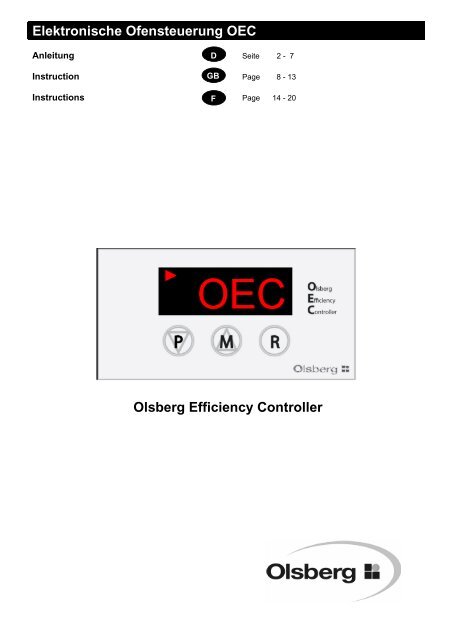
Elektronische Ofensteuerung OEC Olsberg Efficiency Controller
Elektronische Ofensteuerung OEC Olsberg Efficiency Controller
Elektronische Ofensteuerung OEC Olsberg Efficiency Controller

Create successful ePaper yourself
Turn your PDF publications into a flip-book with our unique Google optimized e-Paper software.
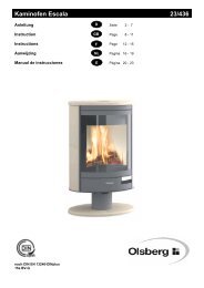
<strong>Elektronische</strong> <strong>Ofensteuerung</strong> <strong>OEC</strong><br />
Anleitung D Seite 2 - 7<br />
Instruction GB Page 8 - 13<br />
Instructions F<br />
Page 14 - 20<br />
<strong>Olsberg</strong> <strong>Efficiency</strong> <strong>Controller</strong>
Inhaltsübersicht<br />
• Vorwort .................................................. Seite 2<br />
• Montage........................................................... 2-4<br />
• Bedienung ...................................................... 4-7<br />
• Stromausfall ...................................................... 7<br />
• Störungsmeldungen ........................................ 7<br />
• Was ist, wenn? ................................................. 7<br />
Vorwort<br />
Diese elektronische <strong>Ofensteuerung</strong> <strong>OEC</strong> ist ein Spitzenprodukt<br />
moderner Feuerungstechnik.<br />
Mit dem <strong>OEC</strong> wird die Zufuhr der Verbrennungsluft<br />
während des gesamten Abbrandes automatisch geregelt.<br />
Durch das Schließen der Verbrennungsluftzufuhr am<br />
Ende des Abbrandes werden Wärmeverluste in den<br />
Standzeiten des Kaminofens vermieden.<br />
Großer Bedienungskomfort, niedrige Emissionen und<br />
hohe Brennstoffausnutzung charakterisieren die<br />
Funktionsweise des <strong>OEC</strong>.<br />
Ordnungsgemäße Montage sowie richtige Handhabung<br />
und Pflege sind für einen störungsfreien Betrieb<br />
und lange Lebensdauer unerläßlich. Beachten Sie<br />
deshalb alle Hinweise in dieser Anleitung.<br />
Bewahren Sie diese Anleitung gut auf, damit Sie sich<br />
bei Beginn der Heizperiode immer wieder über die<br />
richtige Bedienung informieren können.<br />
Sollten Sie einen Transportschaden feststellen, melden<br />
Sie dies bitte sofort Ihrem Lieferanten, da sonst<br />
keine kostenlose Schadensregulierung möglich ist.<br />
Zu beachtende Vorschriften<br />
• Örtliche und baurechtliche Vorschriften<br />
• Der <strong>OEC</strong> ist von einem Fachmann anzuschließen<br />
und in Betrieb zu nehmen.<br />
2<br />
Montage<br />
Lieferumfang<br />
Die Bauteile in folgenden Montageschritten<br />
am Kaminofen montieren:<br />
• Die Motor-Halteklammer mit Distanzhülse im<br />
Holzlagerfach an der Motorkonsole festschrauben.<br />
Motor-Halteklammer Distanzhülse
• Den Türkontaktschalter hinter der Fülltür auf der<br />
rechten Seite anschrauben.<br />
Das Anschlusskabel vorher durch die Montageöffnung<br />
schieben.<br />
Türkontaktschalter<br />
• Nach dem Einbau die einwandfreie Funktion des<br />
Türkontaktschalters beim Schließen der Fülltür<br />
überprüfen.<br />
→ Die Fülltür muss einwandfrei schließen<br />
→ Der Türkontaktschalter muss beim Öffnen<br />
hörbar klicken.<br />
→ Falls erforderlich, den Türkontaktschalter in<br />
der Tiefe verstellen<br />
• Den Temperaturfühler in die Fühlertasche auf<br />
dem Heizmantel oben einstecken und mit der<br />
Fühlerhülse und der Überwurfmutter festschrauben.<br />
• Das Fühlerkabel hinten am Gerät nach unten<br />
zum Holzlagerfach führen.<br />
Überwurfmutter Fühlerhülse<br />
Temperaturfühler<br />
• Das Kabel der Stromversorgung durch die<br />
Durchführungstülle in der Rückwand unten<br />
schieben.<br />
• Die Kabel, Stromversorgung und Fühlerkabel,<br />
durch die Aussparungen im Blechmantel in das<br />
Holzlagerfach ziehen.<br />
Kabel Stromversorgung Fühlerkabel<br />
• Alle Verbindungskabel zwischen Türkontaktschalter,<br />
Elektronik und Stellmotor einstecken.<br />
3
Stellmotor auf der Drehachse des Luftschieberhebels<br />
aufschieben.<br />
Vorher die Drehachse mit dem Luftschieberhebel<br />
so ausrichten, dass der Stellmotor sich aufschieben<br />
lässt und und gleichzeitig in die Motor-Halteklammer<br />
einschnappt.<br />
4<br />
Stellmotor Motor-Halteklammer<br />
• Elektronik mit Konsole hinter der Holzlagerfachtür<br />
auf der rechten Seite anschrauben.<br />
Bedienung<br />
Funktion<br />
Mit dem Öffnen und wieder Schließen der Fülltür<br />
bekommt die Elektronik das Signal für den Start eines<br />
neuen Abbrandes.<br />
→ Die Luftschieber fahren ganz auf<br />
→ Displayanzeige 100 (100% Luftschieber auf))<br />
Bei Einstellung auf Anzeige Luftschieberstellung.<br />
In der Displayanzeige kann mit den Tasten P oder M<br />
zwischen Feuerraumtemperatur in °C und Luftschieberstellung<br />
in % gewechselt werden.<br />
Nach ca. 1 Minute geht die Displayanzeige aus<br />
Energiespargründen in den Standbymodus.<br />
Zur erneuten Aktivierung die Funktionstasten P oder<br />
M drücken.<br />
Der Startvorgang kann auch durch drücken der Taste<br />
R ausgelöst werden.<br />
Nach 15 Minuten Brenndauer fährt der Luftschieber<br />
in Abhängigkeit der erreichten Feuerraumtemperatur<br />
auf 50% oder 40%.<br />
→ Primärluft ist dann ganz geschlossen<br />
→ Displayanzeige 50 oder 40<br />
Bei Einstellung auf Anzeige Luftschieberstellung.<br />
Der Sekundärluftschieber wird im weiteren Abbrand<br />
stufenweise bis auf 20% geschlossen.<br />
Nach Erreichen von 280°C* ertönt ein akustisches<br />
Signal und die Temperaturanzeige im Display blinkt<br />
als Aufforderung zum „Brennstoff nachlegen“.<br />
*(Regelkurve 2+3 = 280°C, Regelkurve 1 = 200°C)<br />
Diese Aufforderung zum Brennstoff nachlegen dient<br />
lediglich als Orientierungshinweis. Je nach Brennstoff<br />
oder Schornsteinzug kann durchaus eine frühere<br />
oder spätere Brennstoffaufgabe sinnvoll sein.<br />
Wird Brennstoff aufgelegt, so startet der Regelzyklus<br />
von neuem.<br />
Wird kein Brennstoff nachgelegt, so ist in ca. 20 Minuten<br />
die Verbrennungsluftzufuhr komplett geschlossen.<br />
Wird beim Abbrand die Feuerraumtemperatur von<br />
280 °C nicht erreicht, so wertet die Elektronik den<br />
Abbrand als nicht normalen Regelvorgang. Die Luftschieber<br />
bleiben 100 % geöffnet. Erst nach Unterschreiten<br />
von 100 °C fahren die Luftschieber in einem<br />
Schließvorgang ohne Zwischenstufen ganz zu.<br />
Wird während des Abbrandes die Fülltür geöffnet<br />
oder die Taste R gedrückt, so wird ein neuer Abbrandzyklus<br />
gestartet.<br />
→ Die Luftschieber fahren wieder ganz auf und der<br />
Schließvorgang wird neu berechnet<br />
Als Führungsgröße dient die Feuerraumtemperatur.<br />
Da sie nicht im Heizgasstrom gemessen wird, ist sie<br />
nicht als gemessene Abgastemperatur sondern lediglich<br />
als Referenztemperatur für die Steuerung der<br />
Elektronik anzusehen.<br />
Anzünden<br />
Beim Anzünden den Brennstoff auflegen wie in der<br />
Anleitung des Kaminofens beschrieben.<br />
Durch das Öffnen der Fülltür beim Auflegen wird der<br />
Öffnungsvorgang der Luftschieber ausgelöst.<br />
Beim Anzünden wird nicht gewartet bis Grundglut<br />
erreicht ist, sondern nach ca. 2/3 Abbrand die erste<br />
Brennstoffmenge aufgelegt.<br />
Sollte beim Anheizen die Primärluftzeit von 15 Minuten<br />
nicht ausreichen, so kann durch nochmaliges<br />
öffnen der Fülltür oder durch drücken der Taste R der
Primärluftschieber nochmals ganz aufgefahren werden.<br />
Wird die Fülltür im kalten Zustand betätigt ohne einen<br />
Abbrand zu starten, so fahren die Luftschieber nach<br />
10 Minuten wieder zu.<br />
Achtung:<br />
Der Feuerrost muss beim Heizen grundsätzlich offen<br />
sein, da sonst keine Primärluft in den Feuerraum<br />
eintreten kann<br />
→ Bedienhebel Feuerrost herausgezogen<br />
Bedienhebel Feuerrost<br />
Verkürzter oder verlängerter Abbrand<br />
Da die Funktion des Kaminofens in erster Linie vom<br />
nachgeschalteten Schornstein abhängig ist, haben<br />
Sie die Möglichkeit durch Wahl von unterschiedlichen<br />
Regelkurven auf unterschiedliche Schornsteinbedingungen<br />
zu reagieren.<br />
Regelkurve 1:<br />
→ Verlängerter Abbrand<br />
→ Einsatz z.B. bei erhöhtem Schornsteinzug<br />
→ Primärluft schließt nach 10 Minuten<br />
→ Verringerte Sekundärluftzufuhr<br />
→ Signal „Brennstoff nachlegen“ bei unterschreiten<br />
von 200 °C<br />
Regelkurve 2:<br />
→ Normaler Abbrand (Werkseinstellung)<br />
→ Primärluft schließt nach 15 Minuten<br />
→ Signal „Brennstoff nachlegen“ bei unterschreiten<br />
von 280 °C<br />
Regelkurve 3:<br />
→ Verkürzter Abbrand<br />
→ Einsatz bei schlechterem Schornsteinzug<br />
z.B. Übergangszeiten mit erhöhten Außentempe-<br />
raturen<br />
→ Primärluft schließt nach 20 Minuten<br />
→ Erhöhte Sekundärluftzufuhr<br />
→ Signal „Brennstoff nachlegen“ bei unterschreiten<br />
von 280 °C<br />
Desweiteren besteht die Möglichkeit im Betreibermenü<br />
an der Elektronik die Schließzeit der Primärluft im<br />
Bereich von 5 bis 60 Minuten einzustellen.<br />
Anzeigen am Display der Elektronik<br />
Anzeige automatischer Betrieb<br />
→ Leuchtet in Intervallen auf<br />
Anzeige manueller Betrieb<br />
→ Leuchtet in Intervallen auf<br />
Anzeige Luftschieberstellung 100% auf<br />
5
Anzeige Feuerraumtemperatur 380°C<br />
→ Anwahl der Anzeige Feuerraumtemperatur oder<br />
Luftschieberstellung erfolgt über die<br />
Tasten P oder M<br />
P oder M drücken → t-1 → 380 (380°C)<br />
P oder M drücken → S-1→ 100 (100%)<br />
Manuelle Luftschieberbetätigung<br />
M drücken bis Anzeige 100 am Display erscheint und<br />
-manueller Betrieb- (Pfeil links unten im Display)<br />
in Intervallen aufleuchtet.<br />
P 2x drücken = Luftschieber fahren von 100 auf 95 %<br />
P 1x drücken = Luftschieber fahren jeweils in 5%-<br />
Schritten weiter zu<br />
M 1x drücken = Luftschieber fahren jeweils in 5%-<br />
Schritten weiter auf<br />
Die Luftschieber können durch drücken der Tasten P<br />
oder M in 5%-Schritten zu oder auf gefahren werden.<br />
R drücken für erneutes Einschalten der automatischen<br />
Betriebsweise<br />
→ Es wird ein neuer Abbrand gestartet<br />
→ Die Luftschieber fahren ganz auf<br />
→ Anzeige am Display = 100<br />
Betreibermenü<br />
Im Betreibermenü können folgende Einstellungen<br />
vorgenommen werden:<br />
• Schließzeit Primärluft 5 -60’<br />
• Auswahl Regelkurve 1-3<br />
• Akustiksignal ein/aus<br />
• Helligkeit Display<br />
• Displayanzeige bei aktivem Motor ein/aus<br />
• Codewortänderung<br />
Schließzeit Primärluft ändern mit Untermenü PAS<br />
P drücken bis Anzeige PAS am Display erscheint<br />
R drücken = Anzeige 0<br />
P drücken bis Anzeige – 2 erscheint (Codewort)<br />
R drücken = Anzeige PAS<br />
P drücken bis Anzeige C - S erscheint<br />
R drücken = Anzeige 15 (bei Regelkurve 2)<br />
Mit P oder M den gewünschten Wert einstellen<br />
6<br />
R drücken zur Bestätigung<br />
P + M gleichzeitig drücken zum Verlassen des Menüs<br />
Auswahl Regelkurve mit Untermenü tYP<br />
P drücken bis Anzeige PAS am Display erscheint<br />
R drücken = Anzeige 0<br />
P drücken bis Anzeige – 2 erscheint (Codewort)<br />
R drücken = Anzeige PAS<br />
P drücken bis Anzeige tYP erscheint<br />
R drücken = Anzeige 2<br />
Mit P oder M den gewünschten Wert einstellen<br />
R drücken zur Bestätigung<br />
P + M gleichzeitig drücken zum Verlassen des Menüs<br />
Akustiksignal An/Aus mit Untermenü bEP<br />
P drücken bis Anzeige PAS am Display erscheint<br />
R drücken = Anzeige 0<br />
P drücken bis Anzeige – 2 erscheint (Codewort)<br />
R drücken = Anzeige PAS<br />
P drücken bis Anzeige bEP erscheint<br />
R drücken = Anzeige on oder off<br />
Mit P oder M den gewünschten Wert einstellen<br />
R drücken zur Bestätigung<br />
P + M gleichzeitig drücken zum Verlassen des Menüs<br />
Helligkeit Display verändern mit Untermenü JAS<br />
P drücken bis Anzeige PAS am Display erscheint<br />
R drücken = Anzeige 0<br />
P drücken bis Anzeige – 2 erscheint (Codewort)<br />
R drücken = Anzeige PAS<br />
P drücken bis Anzeige JAS erscheint<br />
R drücken = Anzeige 0 - 5<br />
Mit P oder M den gewünschten Wert einstellen<br />
R drücken zur Bestätigung<br />
P + M gleichzeitig drücken zum Verlassen des Menüs<br />
Displayanzeige bei aktivem Motor An/Aus mit<br />
Untermenü Sut<br />
P drücken bis Anzeige PAS am Display erscheint<br />
R drücken = Anzeige 0<br />
P drücken bis Anzeige – 2 erscheint (Codewort)<br />
R drücken = Anzeige PAS<br />
P drücken bis Anzeige Sut erscheint<br />
R drücken = Anzeige on oder off<br />
Mit P oder M den gewünschten Wert einstellen<br />
R drücken zur Bestätigung<br />
P + M gleichzeitig drücken zum Verlassen des Menüs<br />
Codewortänderung mit Untermenü EPS<br />
P drücken bis Anzeige PAS am Display erscheint<br />
R drücken = Anzeige 0<br />
P drücken bis Anzeige – 2 erscheint (Codewort)<br />
R drücken = Anzeige PAS<br />
P drücken bis Anzeige EPS erscheint<br />
R drücken = Anzeige - 2<br />
Mit P oder M den gewünschten Wert einstellen
R drücken zur Bestätigung<br />
P + M gleichzeitig drücken zum Verlassen des Menüs<br />
Stromausfall<br />
Bei Stromausfall kann die Luftregulierung über den<br />
Luftschieberstellhebel vorgenommen werden.<br />
Hierzu muss das Getriebe des Stellmotors mit dem<br />
am Drehpunkt des Stellmotors aufgestecktem Magnetschlüssel<br />
wie folgt entriegelt werden:<br />
Den Magnetschlüssel am Drehpunkt abziehen und<br />
mit dem Magnetteil, wie unten abgebildet, auf dem<br />
Stellmotor aufsetzen.<br />
Magnetschlüssel<br />
Automatischer Betrieb<br />
Handbetrieb bei Stromausfall<br />
Störungsmeldungen:<br />
Folgende Störungsmeldungen werden am Display<br />
angezeigt:<br />
Hi oder Lo → Der Temperaturfühler ist defekt.<br />
In diesem Fall muss der Temperaturfühler ausgetauscht<br />
werden.<br />
Was ist, wenn?<br />
... der Kaminofen nicht richtig zieht?<br />
• Ist der Schornstein oder das Ofenrohr undicht?<br />
• Ist der Schornstein nicht richtig bemessen?<br />
• Ist die Außentemperatur zu hoch?<br />
• Ist die Tür anderer, an den Schornstein angeschlossener<br />
Feuerstätten offen?<br />
• Muss Regelkurve 3 eingestellt werden?<br />
• Muss die Primärluftzeit verlängert werden?<br />
... der Raum nicht warm wird?<br />
• Ist der Wärmebedarf zu hoch?<br />
• Ist das Abgasrohr verstopft?<br />
• Ist der Schornsteinzug zu niedrig?<br />
• Ist das Brennholz nicht trocken?<br />
• Muss Regelkurve 3 eingestellt werden?<br />
• Muss die Primärluftzeit verlängert werden?<br />
... der Kaminofen eine zu hohe Heizleistung abgibt?<br />
• Ist der Förderdruck zu hoch?<br />
• Muss Regelkurve 1 eingestellt werden?<br />
... Schäden an der Rosteinrichtung auftreten oder<br />
sich Schlacke bildet?<br />
• Der Kaminofen wurde überlastet?<br />
• Der Aschekasten wurde nicht rechtzeitig entleert?<br />
7
Electronic Oven <strong>Controller</strong> <strong>OEC</strong><br />
Instruction GB<br />
Page 8 - 13<br />
Table of contents<br />
• Foreword ............................................... Page 8<br />
• Installation .....................................................8-10<br />
• Operation .....................................................10-13<br />
• Power Failure.................................................... 13<br />
• Fault Indications.............................................. 13<br />
• What happens if? ........................................... 13<br />
Foreword<br />
This electronic oven controller <strong>OEC</strong> is a top product<br />
of modern firing technology.<br />
In the <strong>OEC</strong>, the combustion air supply is automatically<br />
controlled during the entire combustion cycle.<br />
Through the shut-off of the combustion air supply at<br />
the end of the combustion cycle, heat losses are<br />
avoided during chimney stove downtime.<br />
High operating comfort, low emissions and high fuel<br />
utilisation characterise the mode of operation of the<br />
<strong>OEC</strong>.<br />
Proper installation as well as correct handling and<br />
care are vital to trouble-free operation and a long life.<br />
Therefore, please follow all the instructions in this<br />
manual.<br />
Keep this manual on hand so that you can always<br />
consult it as to correct operation at the beginning of<br />
the heating period.<br />
If you discover any transport damage, please report<br />
this to your supplier immediately; otherwise there can<br />
be no settlement claims free of charge.<br />
Instructionslines<br />
• Local building regulations<br />
• The <strong>OEC</strong> must be connected and put into operation<br />
by a qualified professional.<br />
8<br />
Installation<br />
Delivery Contents<br />
Install the components on the chimney<br />
stove in the following installation steps.<br />
• Screw the motor retaining clip with the spacer<br />
sleeve in the wood storage compartment on the<br />
motor console.<br />
Motor retaining clip Spacer sleeve
• Screw on the door contact switch behind the<br />
furnace chamber door on the right side.<br />
First, push the connection cable through the installation<br />
opening.<br />
Door contact switch<br />
• After the installation, check to make sure that the<br />
door contact switch works perfectly when the furnace<br />
chamber door is closed.<br />
→ The furnace chamber door must close per<br />
fectly<br />
→ The door contact switch must click<br />
audibly when the door is opened<br />
→ If necessary, adjust the depth of the<br />
door contact switch<br />
• Push the temperature sensor into the sensor<br />
pocket on top of the heating jacket and screw<br />
tight with the sensor sleeve and the union nut.<br />
• Connect the sensor cableto the back of the unit<br />
down to the wood storage compartment.<br />
Union nut Sensor sleeve<br />
temperature sensor:<br />
• Push the cable of the power supply through the<br />
grommet in the back wall at the bottom.<br />
• Pull the power supply cable and sensor cable<br />
through the recesses in the metal cover into the<br />
wood storage compartment.<br />
Power supply cable Sensor cable<br />
• Plug in all connecting cables between the door<br />
contact switch, electronics and servo motor.<br />
9
Push the servo motor onto the rotation axis of the air<br />
regulator lever.<br />
First, align the rotation axis with the air regulator lever<br />
so that the servo motor can be pushed on and<br />
simultaneously snaps into place in the motor retaining<br />
clamp.<br />
10<br />
Servo motor Motor retaining clip<br />
• Screw on the electronics with the console behind<br />
the furnace chamber door on the right side.<br />
Operation<br />
Function<br />
When the furnace chamber door opens and closes<br />
again, the electronics receives the signal to start a<br />
new combustion cycle.<br />
→ The air regulators open up completely<br />
→ Display = 100 (air regulators open 100%)<br />
If setup to display the air regulator setting.<br />
The P or M buttons can be used to change between<br />
the fire chamber temperature in °C and the air regulator<br />
setting in %.<br />
After approx. 1 minute, the display goes into stand-by<br />
mode to save energy.<br />
Press the P or M function button to activate it again.<br />
The starting process can be initiated by pressing the<br />
R button.<br />
After 15 minutes of burning, the air regulator changes<br />
to 50% or 40% depending on the fire chamber temperature<br />
that has been reached.<br />
→ The primary air is then shut off completely<br />
→ Display shows 50 or 40<br />
If setup to display the air regulator setting.<br />
The secondary air regulator is shut down gradually to<br />
20% as the combustion cycle continues.<br />
An acoustic signal sounds when 280 °C is reached<br />
and the temperature in the display flashes as a<br />
prompt to "Replenish fuel".<br />
*(Control curve 2+3 = 280°C, Control curve 1 =<br />
200°C)<br />
This prompt to replenish the fuel only serves as orientation<br />
information. Depending on the fuel or chimney<br />
draught, it is quite possible that it makes sense<br />
to add fuel sooner or later.<br />
When fuel has been added, the control cycle starts<br />
again from the beginning.<br />
If no fuel is added, then the combustion air supply is<br />
completely shut off after approx. 20 minutes.<br />
If a fire chamber temperature of 280 °C is not reached<br />
during the combustion cycle, then the electronics<br />
rates the combustion cycle as an abnormal control<br />
procedure. The air regulators remain 100% open.<br />
Only after dropping below 100 °C, will the air regulators<br />
close completely in a closing procedure without<br />
any intermediate steps.<br />
If the furnace chamber door is opened during the<br />
combustion cycle or the R button is pressed, then a<br />
new combustion cycle is started.<br />
→ The air regulators open completely once again<br />
and the closing process is recalculated<br />
The fire chamber temperature serves as a command<br />
variable. Since it is not measured in the hot gas flow,<br />
it is not to be regarded as the measured flue gas<br />
temperature, but merely as a reference temperature<br />
for controlling the electronics.<br />
Ignition<br />
For ignition, place the fuel as described in the chimney<br />
stove's instructions.<br />
The opening procedure of the air regulators is initiated<br />
by opening the furnace chamber door and putting<br />
in the fuel.<br />
Ignition does not wait until there are glowing embers;<br />
rather the first quantity of fuel is added after approx.<br />
2/3 of the combustion cycle.<br />
If 15 minutes of primary air is insufficient during firing<br />
up, the primary air regulator can then be completely<br />
reopened by opening the furnace chamber door<br />
again or by pressing the R button.
If a fire chamber temperature of 100°C is not reached<br />
during firing up after 10 minutes, the air regulators<br />
close completely again.<br />
Attention:<br />
The fire grate must normally be open during heating,<br />
otherwise no primary air can enter into the fire chamber.<br />
→ Operating lever of fire grate pulled out<br />
Fire grate operating lever<br />
Shortened or extended combustion cycle<br />
Since the operation of the chimney stove is primarily<br />
dependent on the downstream chimney, you have<br />
the possibility of reacting to different chimney conditions<br />
by choosing different control curves.<br />
Control curve 1:<br />
→ Extended combustion cycle<br />
→ Use, for example, with increased chimney<br />
draught<br />
→ Primary air shuts off after 10 minutes<br />
→ Reduced secondary air supply<br />
→ "Add fuel" signal if temperature drops<br />
below 200 °C<br />
Control curve 2:<br />
→ Normal combustion cycle (factory setting)<br />
→ Primary air shuts off after 15 minutes<br />
→ "Add fuel" signal if temperature drops<br />
below 280 °C<br />
Control curve 3:<br />
→ Reduced combustion cycle<br />
→ Use for poor chimney draught<br />
e.g. transition times with increased<br />
outside temperatures<br />
→ Primary air shuts off after 20 minutes<br />
→ Increased secondary air supply<br />
→ "Add fuel" signal if temperature drops<br />
below 280 °C<br />
Furthermore, there is the possibility of setting the<br />
shut-off time of the primary air in a range of 5 to 60<br />
minutes for the electronics in the operator menu.<br />
The display of the electronics<br />
Indicates automatic mode<br />
→ Illuminates in intervals<br />
Indicates instructions mode<br />
→ Illuminates in intervals<br />
Indicates air regulator setting is 100% open<br />
11
Indicates a fire chamber temperature of 380 °C<br />
→ Select the fire chamber temperature or<br />
air regulator setting display using the<br />
P or M buttons<br />
Press P or M → t-1 → 380 (380°C)<br />
Press P or M → S-1 → 100 (100%)<br />
Instructions air regulator operation<br />
Press M until 100 appears on the display and<br />
-instructions mode- (arrow on bottom left of display)<br />
illuminates in intervals.<br />
Press P 2x = move air regulator from 100 to 95%<br />
Press P 1x = air regulator closes in 5%<br />
increments each time<br />
Press M 1x = air regulator opens in 5%<br />
increments each time<br />
The air regulator can be opened or closed in 5%<br />
increments by pressing the P or M buttons.<br />
Press R to change back to automatic mode once<br />
again<br />
→ A new combustion cycle is started<br />
→ The air regulators open completely<br />
→ Shown in display = 100<br />
Operator's menu<br />
The following settings can be made in the operator's<br />
menu:<br />
• Primary air shut-off time 5 - 60'<br />
• Select control curve 1-3<br />
• Acoustic signal on/off<br />
• Display brightness<br />
• Display on/off when motor active<br />
• Code word change<br />
Change primary air shut-off time with sub-menu<br />
PAS<br />
Press P until PAS appears in the display<br />
Press R = 0 in display<br />
Press P until PAS appears in the display<br />
Press R = PAS in display<br />
Press P until C - S appears in the display<br />
12<br />
Press R = 15 in display (for control curve 2)<br />
Set the desired value with P or M<br />
Press R to confirm<br />
Press P + M simultaneously to exit the menu<br />
Select control curve with sub-menu tYP<br />
Press P until PAS appears in the display<br />
Press R = 0 in display<br />
Press P until PAS appears in the display<br />
Press R = PAS in display<br />
Press P until tYP appears in the display<br />
Press R = 2 in display<br />
Set the desired value with P or M<br />
Press R to confirm<br />
Press P + M simultaneously to exit the menu<br />
Acoustic signal on/off with sub-menu bEP<br />
Press P until PAS appears in the display<br />
Press R = 0 in display<br />
Press P until PAS appears in the display<br />
Press R = PAS in display<br />
Press P until bEP appears in the display<br />
Press R = display on or off<br />
Set the desired value with P or M<br />
Press R to confirm<br />
Press P + M simultaneously to exit the menu<br />
Change display brightness with sub-menu JAS<br />
Press P until PAS appears in the display<br />
Press R = 0 in display<br />
Press P until PAS appears in the display<br />
Press R = PAS in display<br />
Press P until JAS appears in the display<br />
Press R = 0 - 5 in display<br />
Set the desired value with P or M<br />
Press R to confirm<br />
Press P + M simultaneously to exit the menu<br />
Display on/off when motor active with<br />
sub-menu Sut<br />
Press P until PAS appears in the display<br />
Press R = 0 in display<br />
Press P until PAS appears in the display<br />
Press R = PAS in display<br />
Press P until Sut appears in the display<br />
Press R = display on or off<br />
Set the desired value with P or M<br />
Press R to confirm<br />
Press P + M simultaneously to exit the menu<br />
Code word change with sub-menu EPS<br />
Press P until PAS appears in the display<br />
Press R = 0 in display<br />
Press P until PAS appears in the display<br />
Press R = PAS in display<br />
Press P until EPS appears in the display<br />
Press R = 2 in display<br />
Set the desired value with P or M<br />
Press R to confirm<br />
Press P + M simultaneously to exit the menu
Power failure<br />
In the event of a power failure, the air can be regulated<br />
using the air regulator control lever.<br />
To do this, the gearbox of the servo motor must be<br />
disengaged as follows with the magnetic key fitted on<br />
the point of rotation of the servo motor:<br />
Pull the magnetic key off the point of rotation and put<br />
it on the servo motor with the magnetic part as shown<br />
below<br />
Magnetic key<br />
Automatic mode<br />
Instructions mode during a<br />
power failure<br />
Fault Indications<br />
The following fault indications are shown on the display:<br />
Hi or Lo → The temperature sensor is faulty<br />
The temperature sensor must be replaced in this<br />
case.<br />
What happens if?<br />
... the chimney stove doesn't really draw?<br />
• Is the chimney or the stovepipe leaky?<br />
• Is the chimney not correctly dimensioned?<br />
• Is the outside temperature too high?<br />
• Is the door of another fireplace connected to the<br />
chimney open?<br />
• Does control curve 3 have to be set?<br />
• Does the primary air time have to be extended?<br />
... the room doesn't become warm?<br />
• Is the heat requirement too high?<br />
• Is the flue gas pipe plugged?<br />
• Is the chimney draught too low?<br />
• Is the firewood not dry?<br />
• Does control curve 3 have to be set?<br />
• Does the primary air time have to be extended?<br />
... the chimney stove puts out too much heat?<br />
• Is the the discharge pressure too high?<br />
• Does control curve 1 have to be set?<br />
... damage occurs to the grating or if cinder<br />
forms?<br />
• Was the chimney stove overloaded?<br />
• The ash bin wasn't emptied promptly?<br />
13
Commande de poêle électronique <strong>OEC</strong><br />
Instructions F<br />
Page 14 - 20<br />
Table des matières<br />
• Préambule ............................................. Page 14<br />
• Montage..................................................... 14 à 16<br />
• Commande ............................................... 16 à 19<br />
• Coupure de courant ....................................... 19<br />
• Messages d'erreur .......................................... 19<br />
• Qu'y a-t-il quand … ? ..................................... 20<br />
Préambule<br />
La présente commande de poêle électronique <strong>OEC</strong><br />
est un produit à la pointe de la technique de combustion<br />
moderne.<br />
Avec <strong>OEC</strong>, l'alimentation de l'air de combustion est<br />
régulée automatiquement pendant la totalité de la<br />
flambée.<br />
La fermeture de l'alimentation en air de combustion à<br />
la fin de la combustion permet d'éviter les pertes de<br />
chaleur dans les périodes d'arrêt du poêle à bois.<br />
Grand confort de commande, faibles émissions et<br />
haut rendement du combustible caractérisent le<br />
mode de fonctionnement de l'<strong>OEC</strong>.<br />
L'installation dans les règles de l’art, ainsi que<br />
l’utilisation et l'entretien corrects sont indispensables<br />
pour garantir un fonctionnement irréprochable du<br />
produit et une longue durée de vie. C'est pourquoi il<br />
est impératif de respecter toutes les instructions de<br />
ce manuel.<br />
Conserver soigneusement les présentes instructions<br />
afin de pouvoir toujours de nouveau les consulter<br />
pour revoir la commande correcte au début de la<br />
période de chauffe.<br />
Si un dommage imputable au transport devait être<br />
constaté, le signaler immédiatement au fournisseur<br />
car un règlement du sinistre sans frais n'est pas possible<br />
dans le cas contraire.<br />
Directives à respecter<br />
• Directives locales et directives relatives au droit<br />
de construction<br />
• Seul un spécialiste est habilité à procéder au<br />
branchement et à la mise en service de l'<strong>OEC</strong>.<br />
14<br />
Montage<br />
Contenu de la livraison<br />
Monter les composants sur le poêle à<br />
bois en respectant les étapes de montage<br />
suivantes :<br />
• Visser la patte de maintien du moteur avec une<br />
douille d'écartement dans le compartiment d'entreposage<br />
du bois sur la console moteur.<br />
Patte de maintien moteur Douille d'écartement
• Visser le contacteur de porte derrière la porte de<br />
remplissage sur le côté droit.<br />
Introduire au préalable le câble de raccordement<br />
à travers l'ouverture de montage.<br />
Contacteur de porte<br />
• Après le montage, contrôler le fonctionnement<br />
irréprochable du contacteur de porte à la fermeture<br />
de la porte de remplissage.<br />
→ La porte de remplissage doit parfaitement<br />
fermer<br />
→ Le contacteur de porte doit émettre un clic<br />
audible à l'ouverture.<br />
→ Si nécessaire, régler le contacteur de porte<br />
en profondeur<br />
• Enficher la sonde de température en haut dans la<br />
poche à sonde sur la chemise de chauffage et la<br />
visser à fond avec la douille de sonde et l'écrouraccord.<br />
• Passer le câble de sonde derrière l'appareil vers<br />
le bas sur le compartiment d'entreposage du<br />
bois.<br />
Ecrou-raccord Douille de sonde<br />
Sonde de température<br />
• Passer le câble de l'alimentation électrique à<br />
travers la douille de traversée dans la paroi arrière.<br />
• Tirer les câbles d'alimentation électrique et de<br />
sonde à travers les évidements dans la chemise<br />
de tôle dans le compartiment d'entreposage du<br />
bois.<br />
Câble alimentation électrique Câble de sonde<br />
• Enficher tous les câbles de connexion entre le<br />
contacteur de porte, l'électronique et le moteur<br />
de commande<br />
15
• Enfoncer le moteur de commande sur l'axe rotatif<br />
du levier de coulisseaux d'air.<br />
Aligner auparavant l'axe rotatif avec le levier de<br />
coulisseaux d'air de telle manière que le moteur<br />
de commande se laisse enfoncer et qu'il s'enclenche<br />
simultanément dans la patte de maintien<br />
du moteur.<br />
Moteur de commande Agrafe de maintien du moteur<br />
• Visser l'électronique avec la console du côté droit<br />
derrière la porte du compartiment d'entreposage<br />
du bois.<br />
Commande<br />
Fonction<br />
Avec l'ouverture suivie de la fermeture de la porte de<br />
remplissage, l'électronique reçoit le signal de commencement<br />
d'une nouvelle flambée.<br />
→ Les coulisseaux d'air s'ouvrent complètement<br />
→ Affichage sur l'écran 100 (100% d'ouverture des<br />
coulisseaux d'air) avec réglage sur affichage<br />
de la position des coulisseaux d'air.<br />
Dans l'affichage sur l'écran, il est possible de basculer<br />
entre la température du foyer en °C et la position<br />
des coulisseaux d'air en % au moyen des touches P<br />
ou M.<br />
L'affichage passe après env. 1 minute en mode de<br />
veille pour des raisons d'économie d'énergie.<br />
16<br />
Pour une nouvelle activation, appuyer sur les touches<br />
fonctionnelles P ou M.<br />
La procédure de démarrage peut également être<br />
activée en appuyant sur la touche R.<br />
Après une durée de combustion de 15 minutes, le<br />
coulisseau d'air revient sur 50 % ou 4 0% en fonction<br />
de la température de foyer atteinte.<br />
→ L'air primaire est alors totalement fermé<br />
→ Affichage 50 ou 40 sur l'écran<br />
avec réglage sur affichage de la position du coulisseau<br />
d'air.<br />
Le coulisseau d'air secondaire est fermé par étapes<br />
jusqu'à 20 % au fur et à mesure de l'avancement de<br />
la flambée.<br />
Lorsque 280 °C sont atteints, un signal acoustique<br />
retentit et l'affichage de la température dans l'écran<br />
clignote pour réclamer un « chargement de combustible<br />
».<br />
*(courbe de régulation 2+3 = 280 °C, courbe de régu<br />
lation 1 = 200 °C)<br />
Cette demande de chargement de combustible remplit<br />
une fonction purement d'orientation. Suivant le<br />
combustible ou le tirage de la cheminée, il peut<br />
s'avérer tout à fait judicieux de rajouter du combustible<br />
plus tôt ou plus tard.<br />
Si du combustible est rechargé, le cycle de régulation<br />
reprend du début.<br />
S'il n'est pas rajouté de combustible, l'alimentation en<br />
air de combustion est complètement fermée en 20<br />
minutes environ.<br />
Si lors de la flambée, une température de foyer<br />
de 280 °C n'est pas atteinte, l'électronique évalue la<br />
flambée comme un processus de régulation anormal.<br />
Les coulisseaux d'air restent ouverts à 100 %. Ce<br />
n'est que lorsque la température retombe en dessous<br />
de 100 °C que les coulisseaux d'air se referment<br />
complètement au cours d'une procédure de fermeture<br />
sans étape intermédiaire.<br />
Si la porte de remplissage est ouverte ou la touche R<br />
actionnée pendant la flambée, un nouveau cycle de<br />
flambée est démarré.<br />
→ Les coulisseaux d'air s'ouvrent de nouveau en<br />
totalité et la procédure de fermeture est recalculée<br />
La grandeur de référence est la température du<br />
foyer. Du fait que la température n'est pas mesurée<br />
dans le flux de gaz de chauffage, elle doit être considérée<br />
non pas comme la température mesurée des<br />
gaz évacués mais uniquement comme une température<br />
de référence pour la commande de l'électronique.
Allumage<br />
Lors de l'allumage, disposer le combustible de la<br />
manière décrite dans le manuel du poêle à bois.<br />
La procédure d'ouverture des coulisseaux d'air est<br />
déclenchée par l'ouverture de la porte de remplissage<br />
lors de la dépose du combustible.<br />
A l'allumage, on n’attend pas jusqu'à ce qu'il ne reste<br />
plus que de la braise mais après env. 2/3 de combustion,<br />
la première charge de combustible est déposée.<br />
Si la durée d'air primaire de 15 minutes ne devait pas<br />
suffire pour la chauffe initiale, le coulisseau d'air primaire<br />
peut être ouvert encore une fois en totalité par<br />
la réouverture de la porte de remplissage ou par une<br />
nouvelle pression sur la touche R.<br />
Si une température de foyer de 100 °C n'est pas<br />
atteinte après une chauffe initiale de 10 minutes, les<br />
coulisseaux d'air se referment alors complètement.<br />
Attention :<br />
La grille de foyer doit être par principe ouverte pour<br />
le chauffage car dans le cas contraire l'air primaire ne<br />
peut pas pénétrer dans le foyer.<br />
→ Levier de commande grille de foyer sorti<br />
Levier de commande grille de foyer<br />
Flambée raccourcie ou prolongée<br />
Comme la fonction du poêle à bois dépend en premier<br />
lieu de la cheminée auquel il est raccordé en<br />
sortie, il est possible de s'adapter aux conditions<br />
respectives de la cheminée par la sélection de courbes<br />
de régulation variées.<br />
Courbe de régulation 1 :<br />
→ flambée prolongée<br />
→ utilisation par ex, avec un tirant de cheminée<br />
élevé<br />
→ fermeture de l'air primaire au bout de 10 minutes<br />
→ alimentation en air secondaire réduite<br />
→ signal « Chargement de combustible » quand la<br />
température tombe sous 200 °C<br />
Courbe de régulation 2 :<br />
→ flambée normale (réglage en usine)<br />
→ fermeture de l'air primaire au bout de 15 minutes<br />
→ signal « Chargement de combustible » quand la<br />
température tombe sous 280 °C<br />
Courbe de régulation 3 :<br />
→ flambée raccourcie<br />
→ utilisation avec une cheminée tirant mal,<br />
par ex. périodes de transition avec températures<br />
extérieures élevées<br />
→ fermeture de l'air primaire au bout de 20 minutes<br />
→ air secondaire élevé<br />
→ signal « Chargement de combustible » quand la<br />
température tombe sous 280 °C<br />
Il est en outre possible de régler la durée de fermeture<br />
de l'air primaire dans une plage allant de 5 à 60<br />
minutes dans le menu de l'exploitant de l'électronique.<br />
Affichages sur l'écran de l'électronique<br />
Affichage mode automatique<br />
→ s'allume à intervalles<br />
Affichage du mode manuel<br />
→ s'allume à intervalles<br />
17
Affichage de la position de coulisseau d'air ouvert<br />
à 100 %<br />
Affichage température du foyer 380 °C<br />
→ Sélection de l'affichage de la température du<br />
foyer ou de la position du coulisseau d'air<br />
effectuée au moyen des touches P ou M<br />
Appuyer sur P ou M → t-1 → 380 (380 °C)<br />
Appuyer sur P ou M → S-1→ 100 (100 %)<br />
Actionnement manuel du coulisseau d'air<br />
Appuyer sur M jusqu'à ce que l'écran affiche 100 et<br />
que<br />
-Mode manuel- (flèche à gauche en bas de l'écran)<br />
s'allume par intervalles.<br />
Actionner 2 fois P = les coulisseaux d'air vont de<br />
100 à 95 %<br />
Actionner une fois P = les coulisseaux d'air se fer<br />
ment de 5 % respectivement<br />
Actionner 1 fois M = les coulisseaux d'air s'ouvrent<br />
de 5 % respectivement<br />
Les coulisseaux d'air peuvent être ouverts ou fermés<br />
par étapes de 5 % en appuyant sur les touches P ou<br />
M.<br />
Appuyer sur R pour une nouvelle mise en service du<br />
mode de service automatique<br />
→ une nouvelle flambée est démarrée<br />
→ les coulisseaux d'air s'ouvrent complètement<br />
→ affichage sur l'écran = 100<br />
18<br />
Menu de l'exploitant<br />
Il est possible de procéder aux réglages suivants<br />
dans le menu de l'exploitant :<br />
• durée de fermeture de l'air primaire 5 à 60<br />
min.<br />
• Sélection courbe de régulation 1 à 3<br />
• Signal acoustique marche/arrêt<br />
• Luminosité de l'écran<br />
• Affichage sur écran avec moteur actif marche/arrêt<br />
• Modification du mot de code<br />
Modifier la durée de fermeture de l'air primaire<br />
dans le sous-menu PAS<br />
Appuyer sur P jusqu'à ce que PAS soit affiché sur<br />
l'écran<br />
Appuyer sur R = affichage 0<br />
Appuyer sur P jusqu'à ce que – 2 soit affiché (mot de<br />
code)<br />
Appuyer sur R = affichage PAS<br />
Appuyer sur P jusqu'à ce que C - S soit affiché<br />
Appuyer sur R = affichage 15 (avec courbe de régulation<br />
2)<br />
Régler la valeur désirée avec P ou M.<br />
Actionner R pour confirmer.<br />
Appuyer simultanément sur P + M pour quitter le<br />
menu.<br />
Sélection courbe de régulation avec sous-menu<br />
tYP<br />
Appuyer sur P jusqu'à ce que PAS soit affiché sur<br />
l'écran<br />
Appuyer sur R = affichage 0<br />
Appuyer sur P jusqu'à ce que – 2 soit affiché (mot de<br />
code)<br />
Appuyer sur R = affichage PAS<br />
Appuyer sur P jusqu’à ce que tYP soit affiché<br />
Appuyer sur R = affichage 2<br />
Régler la valeur désirée avec P ou M.<br />
Actionner R pour confirmer.<br />
Appuyer simultanément sur P + M pour quitter le<br />
menu.<br />
Marche/arrêt du signal acoustique avec le sousmenu<br />
bEP<br />
Appuyer sur P jusqu'à ce que PAS soit affiché sur<br />
l'écran<br />
Appuyer sur R = affichage 0<br />
Appuyer sur P jusqu'à ce que – 2 soit affiché (mot de<br />
code)<br />
Appuyer sur R = affichage PAS<br />
Appuyer sur P jusqu’à ce que bEP soit affiché<br />
Appuyer sur R = affichage marche ou arrêt<br />
Régler la valeur désirée avec P ou M.<br />
Actionner R pour confirmer.<br />
Appuyer simultanément sur P + M pour quitter le<br />
menu.
Modifier la luminosité de l'écran avec le sousmenu<br />
JAS<br />
Appuyer sur P jusqu'à ce que PAS soit affiché sur<br />
l'écran<br />
Appuyer sur R = affichage 0<br />
Appuyer sur P jusqu'à ce que – 2 soit affiché (mot de<br />
code)<br />
Appuyer sur R = affichage PAS<br />
Appuyer sur P jusqu’à ce que JAS soit affiché<br />
Appuyer sur R = affichage 0 à 5<br />
Régler la valeur désirée avec P ou M.<br />
Actionner R pour confirmer.<br />
Appuyer simultanément sur P + M pour quitter le<br />
menu.<br />
Affichage sur l'écran avec le moteur actif marche/arrêt<br />
au moyen du sous-menu Sut<br />
Appuyer sur P jusqu'à ce que PAS soit affiché sur<br />
l'écran<br />
Appuyer sur R = affichage 0<br />
Appuyer sur P jusqu'à ce que – 2 soit affiché (mot de<br />
code)<br />
Appuyer sur R = affichage PAS<br />
Appuyer sur P jusqu’à ce que Sut soit affiché<br />
Appuyer sur R = affichage marche ou arrêt<br />
Régler la valeur désirée avec P ou M.<br />
Actionner R pour confirmer.<br />
Appuyer simultanément sur P + M pour quitter le<br />
menu.<br />
Modification du mot de code avec le sous-menu<br />
EPS<br />
Appuyer sur P jusqu'à ce que PAS soit affiché sur<br />
l'écran<br />
Appuyer sur R = affichage 0<br />
Appuyer sur P jusqu'à ce que – 2 soit affiché (mot de<br />
code)<br />
Appuyer sur R = affichage PAS<br />
Appuyer sur P jusqu’à ce que EPS soit affiché<br />
Appuyer sur R = affichage - 2<br />
Régler la valeur désirée avec P ou M.<br />
Actionner R pour confirmer.<br />
Appuyer simultanément sur P + M pour quitter le<br />
menu.<br />
Coupure de courant<br />
La régulation d'air peut être effectuée au moyen du<br />
levier de coulisseaux d'air en cas de coupure de<br />
courant.<br />
Pour cela, le réducteur du moteur de commande doit<br />
être déverrouillé de la manière suivante avec la clé<br />
magnétique enfichée au point de rotation du moteur<br />
de commande :<br />
ôter la clé magnétique au point de rotation et la disposer<br />
sur le moteur de commande avec la partie<br />
magnétique de la manière représentée ci-dessous.<br />
Clé magnétique<br />
Mode automatique<br />
Mode manuel en cas de cou<br />
pure de courant<br />
Messages d'erreur :<br />
Les messages d'erreur suivants sont affichés sur<br />
l'écran :<br />
Hi ou Lo → la sonde de température est défectueuse.<br />
Il faut dans ce cas la remplacer.<br />
19
Qu'y a-t-il quand … ?<br />
... le poêle à bois ne tire pas correctement ?<br />
• La cheminée ou le tube du poêle ont-ils une fuite<br />
?<br />
• La cheminée n'est-elle pas correctement dimensionnée<br />
?<br />
• La température extérieure est-elle trop élevée ?<br />
• La porte d'autres foyers connectés à la cheminée<br />
est-elle ouverte ?<br />
• Faut-il régler la courbe de régulation 3 ?<br />
• L'air primaire doit-il être prolongé ?<br />
... la pièce ne chauffe pas ?<br />
• Le besoin en chaleur est-il trop élevé ?<br />
• Le tube de gaz évacués est-il bouché ?<br />
• La cheminée ne tire-t-elle pas assez ?<br />
20<br />
<strong>Olsberg</strong> Hermann Everken GmbH<br />
Hüttenstraße 38 • D - 59939 <strong>Olsberg</strong><br />
Email: info@olsberg.com<br />
www.olsberg.com<br />
• Le bois de combustion n'est-il pas sec ?<br />
• Faut-il régler la courbe de régulation 3 ?<br />
• L'air primaire doit-il être prolongé ?<br />
... la puissance de chauffe du poêle à bois est<br />
trop forte ?<br />
• La pression de refoulement est-elle trop élevée ?<br />
• Faut-il régler la courbe de régulation 1 ?<br />
... des dommages du dispositif de grille apparaissent<br />
ou des scories se forment ?<br />
• Le poêle à bois a-t-il été en surcharge ?<br />
R0 TNr. 78/4623.5753 06/2010