24VDC MOTORS 205/BLi924 - Cardin Elettronica
24VDC MOTORS 205/BLi924 - Cardin Elettronica
24VDC MOTORS 205/BLi924 - Cardin Elettronica
- No tags were found...

You also want an ePaper? Increase the reach of your titles
YUMPU automatically turns print PDFs into web optimized ePapers that Google loves.
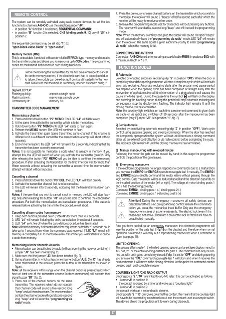
REMOTE CONTROLThe system can be remotely activated using radio control devices; to set the twofunctions to channels A-B-C-D use the selection jumper “J4":- in position “A" function 1 is selected, SEQUENTIAL COMMAND;- in position “B" function 2 is selected, CH2 (binding posts 9, 10) only if "J5" is inposition 2.The sequential command may be set (dip “1") to:“open-block-close-block" or “open-close".Memory module (MM)This is extractable, furnished with a non volatile EEPROM type memory and containsthe transmitter codes and allows you to memorise up to 300 codes. The programmedcodes are maintained in this module even during blackouts.Signal LED "L4"Flashing quickly:Flashing slowly:Permanently lit:Before memorising the transmitters for the first time remember to cancelthe entire memory content. If the electronic card has to be replaced dueto failure, the module can be extracted from it and inserted into the newcard. Make sure that the module is correctly inserted as shown on fig. 2.TRANSMITTER CODE MANAGEMENTcancels a single codememorises a single codememory full.Memorising a channel1. Press and hold down button "P2" MEMO: The LED "L4" will flash slowly.2. At the same time activate the transmitter which is to be memorised.3. Hold down button "P2" MEMO until LED "L4" starts to flash again.4. Release the MEMO button: The LED will continue to flash.5. Activate the transmitter again (same transmitter, same channel; if the channel isdifferent or it is a different transmitter the memorisation attempt will abort withoutsuccess).6. End of memorisation: the LED "L4" will remain lit for 2 seconds, indicating that thetransmitter has been correctly memorised.Notes: It is not possible to memorise a code which is already in memory: if youattempt this, the LED will switch off when you activate the transmitter (point 2). Onlyafter releasing the button "P2" MEMO will you be able to continue the memorisingprocedure. If after activating the transmitter for the first time you wait for more thanfifteen seconds without activating the transmitter a second time the memorisationattempt will abort without success.Cancelling a channel1. Press and hold down the button "P3" DEL: the LED "L4" will flash quickly.2. Activate the transmitter channel that is to be cancelled.3. The LED will remain lit for 2 seconds, indicating that the transmitter has been cancelled.Notes: If the user that you wish to cancel is not in memory, the LED will stop flashing;only after releasing the button "P3" will you be able to continue the cancellationprocedure. For both the memorisation and cancellation procedures, if the button isreleased before activating the transmitter the procedure will abort.Cancelling all user codes from memory1. Keep both buttons pressed down ("P2+P3") for more than four seconds.2. LED "L4" will remain lit during the entire cancellation time (about 8 seconds).3. LED "L4" switches off when the cancellation procedure has terminated.Note: When the memory is almost full the time required to search for a user code couldtake up to 1 second from when the command was received. If LED "L4" remains litmemory is completely full. To memorise a new transmitter you will first have to cancela code from memory.All rights reserved. Unauthorised copying or use of the information contained in this document is punishable by lawMemorising ulterior channels via radio• Memorisation can be activated by radio (without opening the receiver container) ifjumper "J3" has been inserted (fig. 2).1. Make sure that the jumper "J3" has been inserted (fig. 2).2. Using a transmitter, in which at least one channel button "A, B, C or D" has alreadybeen memorised in the receiver, press the button in the transmitter as shown infigure.Note: all the receivers within range when the channel button is pressed (and whichhave at least one of the transmitter channel buttons memorised) will activate theirsignal buzzer "B1" (fig. 2).3. Press one of the channel buttons on the sametransmitter. The receivers which do not containthat channel code will sound a five-second long"beep" and will then deactivate. The receivers whichcontain the channel code will sound a one-secondlong "beep" and will enter the "programming viaradio" mode.MR174. Press the previously chosen channel buttons on the transmitter which you wish tomemorise; the receiver will sound 2 "beeps" of half a second each after which thereceiver will be ready to receive another code.5. To leave the programming mode wait for 3 seconds without pressing any buttons.The receiver will sound a five-second long "beep" and will then exit the programmingmode.Note: When the memory is entirely occupied the buzzer will sound 10 rapid "beeps"and will automatically leave the "programming via radio" mode. LED "L4" will remainlit on the receiver. The same signal is given each time you try to enter "programmingvia radio" when the memory is full.CONNECTING THE ANTENNAConnect an ANS400 tuned antenna using a coaxial cable RG58 (impedance 50Ω) witha maximum length of 15 m.FUNCTION MODES1) AutomaticSelected by enabling automatic reclosing (dip "2" in position "ON"). When the door iscompletely closed the opening command will start a complete cycle which will end withautomatic reclosing. Automatic reclosing starts after the programmed pause periodhas elapsed when the opening cycle has been completed or straight away after theintervention of a photoelectric cell (the intervention of a photoelectric cell causes thepause time to be reset). During the pause time the symbol will flash on the displayand pressing the blocking button during this period will stop automatic reclosing andconsequently stop the display from flashing. The indicator light remains lit until theclosing manoeuvre has terminated.Note: the courtesy light switches on each time a movement command is given (bothvia cable or via radio) and switches off 30 seconds after the manoeuvre has beencompleted (only if jumper "J5" is in position "1", fig. 2).2) SemiautomaticSelected by deactivating automatic reclosing (dip "2" in position "OFF"). Work cyclecontrol using separate opening and closing commands. When the door has reachedthe completely open position the system will wait until it receives a closing commandeither via an external control button or via radio control, before completing the cycle.The indicator light remains lit until the closing manoeuvre has terminated.3) Manual manoeuvring with released motorsReleasing the motor the gate can be moved by hand; in this stage the programmercontrols the position of the gate leaves.4) Emergency manoeuvreIf the electronic programmer no longer responds to commands due to a malfunctionyou may use the EMRG1 or EMRG2 inputs to move gate leaf 1 manually. The EMRG1and EMRG2 inputs directly command the motor relays without passing through thelogic control. Gate movement will be at reduced speed and the direction depends onthe installed position of the motor (left or right). The voltage at motor binding posts 1and 2 has the following polarity:Command EMRG1: binding post 1 (+) binding post 2 (-)Command EMRG2: binding post 1 (-) binding post 2 (+)Attention! During the emergency manoeuvre all safety devices aredisabled and there is no gate positioning control: release the commandsbefore you are at the mechanical travel buffer. Only use the emergencymanoeuvre in cases of extreme necessity. The electric lock (even if it isenabled) is not active. Therefore if an electric lock is fitted it will have tobe activated manually.After you have carried out an emergency manoeuvre the electronic programmer willlose the position of the gate leaf ( on the display) and therefore when normaloperation is restored it will carry out a repositioning manoeuvre when a command isgiven (see page 15).LIMITED OPENINGThis always effects gate 1; the limited opening space can be set (see display menu) to1/3, half, 2/3 or the entire opening distance for gate 1. The command can only be carriedout with both gates completely closed; if dip 1 is set to “OFF" and during openingyou activate the “TAL" command again gate leaf 1 will block and when it receives thenext command it will move in the closing direction. At this point the command cannotbe used again until complete closure.COURTESY LIGHT /CH2 RADIO OUTPUTBinding posts “9 ","10 " are linked to a C-NO relay; this can be activated as follows.• Jumper J5 in position 1:the contact is closed by a timer and works as a “courtesy light"• Jumper J5 in position 2:the contact works as a second radio channel.Binding posts “9 ","10" only give a potential free contact; this means that the courtesy lightwill have to be powered by an external circuit and the contact used as a simple switch.This device allows the propulsion unit to work during blackouts.