FT/SB/07
FT/SB/07
FT/SB/07
- No tags were found...

You also want an ePaper? Increase the reach of your titles
YUMPU automatically turns print PDFs into web optimized ePapers that Google loves.
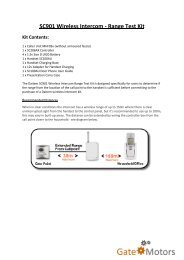
AvvertenzeWarningsInstructionsHinweiseI• Evitare di porre i fili di montante in prossimità di cavi di alimentazione (220/380V).•Connettere il telaio portamoduli a terra (vedi fig. 1).•Effettuare l’installazione seguendo scrupolosamente le istruzioni fornitedal costruttore ed in conformità alle normative vigenti.•Tutti gli apparecchi devono essere destinati esclusivamente all’usoper cui sono stati concepiti.GB •Avoid placing the riser wires near power supply cables (220/380V).• Connect the module-holder frame to earth (see fig. 1).• Carry out installation following the manufacturer's instructions very carefully,and in compliance with the laws in force.• All the pieces of apparatus must only be used of the purposesthey have been built for.F• Eviter de placer les fils de montant à proximité des câbles d’alimentation (220/380V).•Connecter le cadre porte-modules à la terre (voir fig. 1).•Effectuer l’installation en suivant scrupuleusement les instructions fournies parle constructeur et en vous conformant aux réglementations en vigueur.•Tous les appareils doivent être strictement destinés à l’emploi pour lequel ilsont été conçus.D • Die Drähte der Steigleitungen nicht in der Näheder Stromkabel (220/380 V) verlegen.•Den Rahmen der Modulhalterung mit derErdleitung verbinden (siehe Abb.1).• Die Installationen sind nach den Anweisungendes Herstellers und gemäß den geltendenVorschriften gewissenhaft auszuführen.•Alle Geräte dürfen ausschließlich nur zu demZweck eingesetzt werden, für den sieentwickelt worden sind.<strong>FT</strong>/<strong>SB</strong>/<strong>07</strong>I Citofonia e videocitofonia con cablaggioa 2 fili non polarizzati.GB Door and video entry phone systemsFwith unpolarised 2-wire cabling.Parlophonie et visiophonieavec câblage à 2 fils non polarisés.D Gegensprech - undVideo - Gegensprechanlagen,verdrahtet mit 2 ungepolten Drähten.Fig. 1Sezione conduttori di alimentazione (mm 2 ) per il monitor e posto esternoCross-section of power supply conductors (mm 2 ) for the monitor and the entrance unitSection conducteurs d’alimentation (mm 2 ) pour le moniteur et le poste extérieurQuerschnitt der Versorgungsleitungen (mm2) für den Monitor und die Außenstation1 m 20 m 50 m 100 m 200 m 300 mAlimentazione portaDoor power supplyAlimentation porteStromversorgung TürAlimentazione monitor con art 1536 o 1212/BMonitor power supply with art. 1536 or 1212/BAlimentation moniteur avec art. 1536 ou 1212/BStromversorgung Monitor mit Art. 1536 oder 1212/B*0/12V~0.221.002.50**0/+200.800.801.00 1.50 2.50Alimentazione monitor con art. 1212Monitor power supply with art. 1212Alimentation monitor avec art. 1212Stromversorgung Monitor mit Art. 12120/18V~0/21V~0.22 1.001.00 1.50Regole generali di installazioneGeneral installation instructionsRègles générales d’installationAllgemeine InstallationsregelnI • Connettere al massimo 100 derivatiper ogni montante.• Connettere al massimo 3 derivaticon il medesimo codice utente.• Il sistema può gestire al massimo240 utenti.• In impianti solo citofonici ladistanza massima difunzionamento tra porta ecitofono più lontano è di 400mtindipendentemente dal tipo dicavo utilizzato e dalla tipologiad’impianto.GB • Connect a maximum of 100 unitsfor each riser.• Connect a maximum of 3 units witheach user code.• The system can manage amaximum of 240 users.• In door entry phone onlysystems, the maximum operatingdistance between the door andthe telephone furthest away is400mt regardless of the type ofcable used and the type ofsystem.F• Brancher au maximum 100 dérivéspour chaque montant.• Brancher au maximum 3 dérivésavec le même code usager.• Le système peut gérer 240 usagersau maximum.• Dans des installations exclusivementparlophoniques la distancemaximum de fonctionnement entre laporte et le parlophone le plus éloignéest de 400 m indépendamment dutype de câble utilisé et de latypologie de l’installation.D• Maximal 100 Abzweigungen jeSteigleitung anschließen.• Maximal 3 Abzweigungen mitdemselben Benutzercode anschließen.• Das System ist auf maximal 240Benutzer ausgelegt.• Bei reinen Gegensprechanlagendarf der Abstand zwischen Türund Haustelefon maximal 400 mbetragen, unabhängig von derArt des benutzten Kabels undder Anlage.1
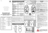
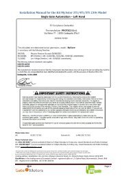
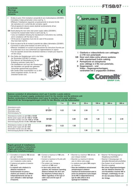
Regole d’installazione per impianti videocitofoniciInstallation instructions for video door entry systemsRègles de montage pour les installations visiophoniquesInstallationsregeln für Video-GegensprechanlagenINelle diramazioni verso ogni utenteinserire sul montante il morsetto 1214fornito a corredo della staffa 4614W/Ao 4714W o del 1561.Terminare ogni montante odiramazione con l’art. 1216 fornito acorredo del modulo video 4660o dell’amplificatore di linea 4833/A.In funzione del cavo utilizzatoper il montante valutare la distanzamassima raggiungibile tra postoesterno videoe la diramazione 1214 più lontana(A1 in figura 2).In funzione del cavo usato per ladiramazione valutare la distanzamassima del monitor dal 1214(B in figura 2).In funzione del cavo usato peril montante impostare la chiusuradell’ art. 1216 come indicatonelle figure 2, 3 e 6.Oltre i 50 utenti è sempre necessarioinserire sul montante un amplificatoredi linea art. 4833/A (figura 3).Indipendentemente dal numero diutenti, per lunghezze di montantesuperiori al limite A1 (figura 3)inserire un amplificatore di lineaart. 4833/A (figura 3).Sul montante, è possibile inserire fino a3 amplificatori di linea art. 4833/A peruna distanza massima totale di 3xA1 ecomunque non superiore ai 400mt.Nel caso di impianti con porte principalie secondarie (figura 4) o comunquequando il montante si divide in piùdiramazioni (figura 5) è necessarioimpiegare il concentratoredi linea art. 4834. L’art. 4834 consenteal massimo 10 diramazioni.Utilizzando il concentratoredi linea è necessario inserireun amplificatore art. 4833/A per ogniuscita del 4834 (fig. 4 e 5).Nel caso di impianti con portesecondarie è consigliabile posizionarel’amplificatore art. 4833/A incorrispondenza dello scambioart. 1224 (figura 4). In funzione delcavo usato per il collegamentovalutare la distanza massimaraggiungibile tra il posto esternovideo e l’amplificatore 4833/Apassando per il concentratore dilinea art. 4834 (C in figura 4 e 5).GB In the branches towards each user,insert terminal 1214 supplied withbracket 4614W/A or 4714W or 1561on the riser.Terminate each riser or branch withart. 1216 provided with videomodules 4660 or with line amplifier4833/A.According to the cable used for theriser, assess the maximum distancewhich can be reached between thevideo external unit and the furthestbranch 1214 (A1 in figure 2).According to the cable used for thebranch, assess the maximumdistance which can be reached fromthe monitor to the branch terminal1214 (B in figure 2).According to the cable used for theriser, set closure of art. 1216 asindicated in figure 2, 3 and 6.With more than 50 users it is alwaysnecessary to insert a line amplifierart. 4833/A (figure 3) on the riser.Regardless of the number of users,for riser lengths over limit A1(figure 3) insert a line amplifierart. 4833/A (figure 3).Up to 3 line amplifiers art. 4833/Acan be inserted on the riser to amaximum total distance of 3xA1 andin any case not more than 400mt.In the case of systems with main andsecondary entrances (figure 4) inany case when the riser divides intoseveral branches (figure 5), it isnecessary to use the lineconcentrator art. 4834.Art. 4834 allows a maximum of 10branches.When using the line concentrator, itis necessary to insert an amplifierart. 4833/A for each output ofart. 4834 (figure 4 and 5).In the case of systems withsecondary entrances, it is advisableto position amplifier art. 4833/A nearthe switching device art. 1224(figure 4).According to the cable used forconnection, assess the maximumdistance which can be reachedbetween the video external unit andthe amplifier art. 4833/A passingthrough line concentrator art. 4834(C in fig. 4 and 5).FDans les embranchements vers chaqueusager insérer sur le montant la borne1214 fournie avec la bride 4614W/A ou4714W ou l’art. 1561.Terminer chaque montant ou chaqueembranchement par l’art. 1216 quiéquipe les modules vidéo 4660 oul’amplificateur de ligne 4833/A.En fonction du câble utilisé pour lemontant évaluer la distance maximumpouvant être atteinte entre le posteextérieur video et l’embranchement leplus éloigné 1214 (A1 figure 2).En fonction du câble utilisé pourl’embranchement évaluer la distancemaximum pouvant être atteinte entrel’embranchement de montant 1214et le moniteur (B figure 2).En fonction du câble utilisé pour lemontant programmer la fermeture del’art. 1216 de la manière indiquée au infigure 2, 3 et 6.Au-delà des 50 usagersil est toujours nécessaire d’insérer sur lemontant un amplificateur de ligneart. 4833/A (fig. 3).Indépendamment du nombre d’usagers,pour des longueurs de montantsupérieures à la limite A1 (figure 3)insérer un amplificateur de ligneart. 4833/A (figure 3).Sur le montant, possibilité d’insérerjusqu’à 3 amplificateurs de ligneart. 4833/A pour une distance totalemaximum de 3xA1 et de toute façonjamais supérieure à 400m.Dans le cas d’installations avec desentrées principales et secondaires(figure 4) ou lorsque le montant sedivise en plusieurs embranchements(figure 5), employer le concentrateur deligne art. 4834.L’art. 4834 consent unmaximum de 10 embranchements.Lors de l’utilisation du concentrateur deligne, il est nécessaire d’insérer unamplificateur art. 4833/A pour chaquesortie de l’art. 4834 (figure 4).Dans le cas d’installations avec desentrées secondaires, il est conseillé demettre en place l’amplificateur art.4833/A en correspondance ducommutateur art. 1224 (figure 4).Enfonction du câble utilisé pour laconnexion, évaluer la distancemaximum pouvant être atteinte entrel’entrée vidéo et l’amplificateur art.4833/A en passant par le concentrateurde ligne art. 4834 (C in figure 4 et 5).DSetzen Sie in jeden Abzweig zu einemBenutzer in der Steigleitung die Klemme1214 ein, die mit dem Sockel 4614W/Aoder 4714W oder 1561 geliefert wird.Schließen Sie jede Steigleitung oderAbzweig mit dem Art. 1216 ab, der mitdem Videomodul 4660 oder demLeitungsverstärker 4833/A geliefert wird.Auf Grundlage des für die Steigleitungverwendeten Kabels muss die maximalmögliche Entfernung zwischen Video-Außenstation und der am weitestenentfernten Abzweigung 1214 (A1 inAbbildung 2) bewertet werden.Auf Grundlage des für den Abzweigverwendeten Kabels muss diemaximal mögliche Entfernung desMonitors vom 1214 bewertet werden(B in Abbildung 2).Auf Grundlage des verwendeten Kabelsfür die Steigleitung muss der Abschlussdes Art. 1216 wie in den Abbildungen2, 3 und 6 erfolgen.Bei mehr als 50 Benutzern muss immerein Leitungsverstärker Art. 4833/Aeingesetzt werden (Abbildung 3).Bei Steigleitungen, die länger sind alsmaximal A1 (Abb. 3), ist unabhängigvon der Benutzerzahl einLeitungsverstärker 4833/A einzusetzen(Abb. 3).Auf der Steigleitung können auf einer400 m nicht übersteigenden Länge von3xA1 bis zu max. 3 Leitungsverstärkern4833/A eingesetzt werden.Bei Anlagen mit Haupt- und Nebentüren(Abbildung 4), bzw. wenn dieSteigleitung sich in mehrere Abzweigeunterteilt (Abbildung 5), muss derLeitungskonzentrator Art. 4834verwendet werden. Der Art. 4834erlaubt maximal 10 Abzweigungen.Wenn man einen Leitungskonzentratorverwendet, muss man an jedenAusgang des 4834 (Abb.4 und 5) einenVerstärker art. 4833/A setzen.Bei Anlagen mit Nebentüren sollte derVerstärker Art. 4833/A im Bereich desUmschalters Art. 1224 montiert werden(Abbildung 4).Auf Grundlage des fürden Anschluss verwendeten Kabelsmuss die maximal mögliche Entfernungzwischen Video-Außenstation und demVerstärker 4833/A mit Durchschleifendes Leitungskonzentrators Art. 4834(C in Abbildung 4 und 5) bewertetwerden.Collegamento in cascata in impianti videocitofoniciCascade connection in video door entry systemsConnexion en cascade dans des installations visiophoniquesKaskadenschaltung bei Video-GegensprechanlagenIIn alternativa all’uso dei morsetti diderivazione art. 1214 e delconcentratore di linea è possibilecollegare gli utenti in cascata (figura 6).In funzione dei cavi utilizzati per ilbus di montante valutare la distanzamassima raggiungibile dal postoesterno video al monitor più lontano(D in figura 6).Terminare ilmontante con l’art. 1216 (figura 6).Indipendentemente dal numero diutenti, per lunghezze di montantesuperiori al limite D (figura 6)inserire un amplificatore di lineaart. 4833/A per una distanzamassima comunque non superioreai 400mt.GB As an alternative to the use ofbranch terminals art. 1214 and lineconcentrator, it is possible to connectthe users in cascade (figure 6).According to the cables used for theriser, assess the maximum distancewhich can be reached from the videoexternal unit to the furthest monitor(D in figure 6).Terminate the riser with art. 1216(figure 6). Regardless of the numberof users, for riser lengths over limit D(figure 6), insert a line amplifier art.4833/A to a maximum distance inany case of not over 400mt.FDans l’alternative à l’emploi des bornesde dérivation art. 1214 et duconcentrateur de ligne, les usagerspeuvent être connectés en cascade(figure 6). En fonction des câblesutilisés pour le montant, évaluer ladistance maximum pouvant êtreatteinte du poste extérieur vidéo aumoniteur le plus éloigné (D figure 6).Terminer le montant avec l’art. 1216(figure 6).Indépendamment dunombre d’usagers pour des longueursde montant supérieures à la limite D(figure 6) insérer un amplificateur deligne art. 4833/A pour une distancemaximum de toute façon jamaissupérieure à 400m.D An Stelle der Abzweigklemmen Art. 1214und des Leitungskonzentrators könnendie Benutzer in Kaskadenschaltungmiteinander verbunden werden (Abb. 6).Auf Grundlage der für den Bus derSteigleitung verwendeten Kabels mussdie maximal mögliche Entfernungzwischen Video-Außenstation und demam weitesten entfernten Monitor (D inAbbildung 6) bewertet werden. DieSteigleitung ist mit dem Art. 1216(Abbildung 6) abzuschließen. BeiSteigleitungen, die länger sind alsmaximal D (Abb. 6), ist unabhängigvon der Benutzerzahl ein Leitungsverstärker4833/A einzusetzen. Die Gesamtlängedarf in jedem Fall 400 m nicht übersteigen.2
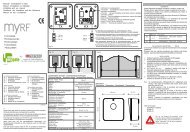
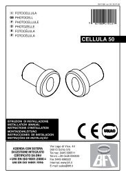
A1Fig. 2Distanza massima tra posto esterno video e diramazione art. 1214 più lontana.Maximum distance between the video entrance unitand the furthest branch terminal art. 1214.Distance maximum entre le poste extérieur vidéo et la borne art. 1214 la plus éloignée.Maximale Entfernung zwischen Video Außenstation und Abzweig Art. 1214Distanza massima del monitor dal art. 1214.Maximum distance between monitor and branch terminal art. 1214.Distance maximum du moniteur de la borne art. 1214.Maximale Entfernung des Monitors zur Klemme Art. 1214N° massimo di utentiMaximum user n°Nombre maximum d’usagersMaximale BenutzerzahlPosizione selettore su terminazione di linea art. 1216.Position of selector on termination of line art. 1216.Position du sélecteur sur la borne de ligne art. 1216.Position des Wählschalters auf dem Leitungsabschluss Art. 1216A1B1216Doppino telefonico twistato o cavoComelit 2x0,5 mm 2 art. 4576Telephone twisted pair or Comelitcable 2x0.5 mm 2 art. 4576Boucle téléphonique twistée oucâble Comelit 2x0.5 mm 2 art. 4576Einfacher Klingeldraht oderComelit Kabel 2x0,5 mm 2 Art. 4576Cavo non intrecciatoUnbraided cableCâble non retorsNicht geflochtenes KabelCavo intrecciato e schermatoBraided and shielded cableCâble retors et blindéGeflochtenes u.abgeschirmtes Kabel150 m 100 m 80 m40 m 20 m 15 m50 50 50A2A1Fig. 3Distanza massima tra posto esterno video e amplificatore art. 4833/A.Maximum distance between the video entrance unit and the amplifier art. 4833/A.Distance maximum entre le poste extérieur vidéo et l’amplificateur art. 4833/A.Maximale Entfernung zwischen Video Außenstation und Verstärker Art. 4833/ADistanza massima tra amplificatore art. 4833/A e diramazione art. 1214 più lontana.Maximum distance between the amplifier art. 4833/A and the furthestbranch terminal art. 1214.Distance maximum entre l’amplificateur art. 4833/A et la borne art. 1214 la plus éloignée.Maximale Entfernung zwischen Verstärker art. 4833/A und dem weitestenentfernten Abzweig Art. 1214N° massimo di utentiMaximum user n°Nombre maximum d’usagersMaximale BenutzerzahlPosizione selettore su terminazione di linea art. 1216.Position of selector on termination of line art. 1216.Position du sélecteur sur la borne de ligne art. 1216.Position des Wählschalters auf dem Leitungsabschluss Art. 1216A1A21216Doppino telefonico twistato o cavoComelit 2x0,5 mm 2 art. 4576Telephone twisted pair or Comelitcable 2x0.5 mm 2 art. 4576Boucle téléphonique twistée oucâble Comelit 2x0.5 mm 2 art. 4576Einfacher Klingeldraht oderComelit Kabel 2x0,5 mm 2 Art. 4576Cavo non intrecciatoUnbraided cableCâble non retorsNicht geflochtenes KabelCavo intrecciato e schermatoBraided and shielded cableCâble retors et blindéGeflochtenes u.abgeschirmtes Kabel150 m 100 m 80 m150 m 100 m 80 m50+50 50+50 50+50CDoppino telefonico twistato o cavoComelit 2x0,5 mm 2 art. 4576Telephone twisted pair or Comelitcable 2x0.5 mm 2 art. 4576Boucle téléphonique twistée oucâble Comelit 2x0.5 mm 2 art. 4576Einfacher Klingeldraht oderComelit Kabel 2x0,5 mm 2 Art. 4576Cavo non intrecciatoUnbraided cableCâble non retorsNicht geflochtenes KabelCavo intrecciato e schermatoBraided and shielded cableCâble retors et blindéGeflochtenes u.abgeschirmtes KabelDistanza massima tra posto esterno video principale e amplificatore art. 4833/A.Maximum distance between the main video entrance unitand the amplifier art. 4833/A.Distance maximum entre le poste extérieur vidéo principaleet l’amplificateur art. 4833/A.Maximale Entfernung zwischen Haupt-Video Außenstation und VerstärkerArt. 4833/AFig. 4C150 m 100 m 80 mDoppino telefonico twistato o cavoComelit 2x0,5 mm 2 art. 4576Telephone twisted pair or Comelitcable 2x0.5 mm 2 art. 4576Boucle téléphonique twistée oucâble Comelit 2x0.5 mm 2 art. 4576Einfacher Klingeldraht oderComelit Kabel 2x0,5 mm 2 Art. 4576Cavo non intrecciatoUnbraided cableCâble non retorsNicht geflochtenes KabelCavo intrecciato e schermatoBraided and shielded cableCâble retors et blindéGeflochtenes u.abgeschirmtes KabelFig. 5CDistanza massima tra posto esterno videoe amplificatore art. 4833/A della diramazione di montante.Maximum distance between the video entrance unitand the branch amplifier art. 4833/A.Distance maximum entre le poste extérieur vidéoet l’amplificateur art. 4833/A du montant.Maximale Entfernung zwischen Video Außenstation und Verstärker Art. 4833/Ades SteigleitungsabzweigsC150 m 100 m 80 m3
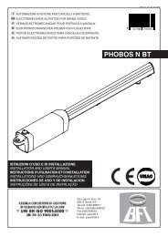
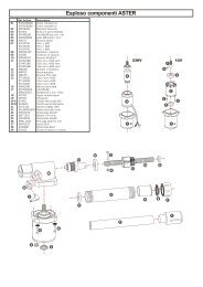
Doppino telefonico twistato o cavoComelit 2x0,5 mm 2 art. 4576Telephone twisted pair or Comelitcable 2x0.5 mm 2 art. 4576Boucle téléphonique twistée oucâble Comelit 2x0.5 mm 2 art. 4576Einfacher Klingeldraht oderComelit Kabel 2x0,5 mm 2 Art. 4576Cavo non intrecciatoUnbraided cableCâble non retorsNicht geflochtenes KabelCavo intrecciato e schermatoBraided and shielded cableCâble retors et blindéGeflochtenes u.abgeschirmtes KabelDDistanza massima tra posto esterno video e monitor piùlontano o amplificatore art. 4833/A in collegamento in cascata.Maximum distance between the video entrance unit and thefurthest monitor or amplifier art. 4833/A in cascade connection.Distance maximum entre le poste extérieur et le moniteur le pluséloigné ou l’amplificateur art. 4833/A avec connexion en cascade.Maximale Entfernung zwischen Video Außenstation und am weitestenentfernten, in Kaskade geschaltetem Monitor oder Verstärker Art. 4833/A.D200 m 130 m 100 mN° massimo utentiMaximum user n°Nombre maximum d’usagers.Maximale Benutzerzahl100 100 100Fig. 6Posizione selettore su terminazione di linea art. 1216.Position of selector on termination of line art.1216.Position du sélecteur sur la borne de ligne art.1216.Position des Wählschalters auf dem Leitungsabschluss Art.12161216Montaggio e collegamento gruppo audio/videoHow to mount and connect the audio/video groupComment monter et relier le groupe audio/vidéoMontage und Verbindung der Audio-Video GruppeMontaggio /Smontaggio frontaliniHow to insert and remove front panelsComment insérer et enlever les façades avantMontage / Demontage der FrontplatteFig. 7 Fig. 8Programmazione pulsanti con gruppo audio e video art. 1602, art.4660 e moduli art. 3323/4 e 3323/6Programming push buttons with audio an video groups art. 1602, art.4660 and p.b. modules art. 3323/4 - 3323/6Programmation des touches avec les groupe audio et vidéo art. 1602, art 4660 et les modules art. 3323/4-3323/6Programmierung der Tasten mit der Audio - und Videogruppe Art. 1602, art. 4660 und den Modulen art. 3323/4 und 3323/6I41. Connettere le morsettieredei moduli 3323/4 e 3323/6tra loro e con la morsettieradel gruppo 4660 o 1602utilizzando gli appositicavetti. Inserire i moduli3323/4 e 3323/6 sullerelative morsettiere (figura 9).2. Sulla morsettiera delmodulo 4660 o 1602collegare l’alimentazione su~~ , connettere PR a --e spostare P/O da OCC aV+ (figura 10) utilizzando ijumper presenti sullamorsettiera stessa.Connettere la morsettiera almodulo 4660 o 1602assemblato come indicatoprecedentemente.(attenzione i moduli 3323/4e 3323/6 da programmaredevono essere giàposizionati) (figura 10).NOTA: per il collegamentotra la morsettiera e ilmodulo 4660 o 1602 in fasedi programmazione èpossibile usare il cavettoart. 3309 disponibile comeaccessorio opzionale(figura 11).GB 1. Connect terminal boardsof p.b. modules art. 3323/4and 3323/6 to each otherand to the terminal board ofunit 4660 or 1602 by meansof provided cables. Insertmodules 3323/4 and 3323/6to relative terminal boards(see picture 9).2. On the terminal board ofunit art. 4660 or 1602connect power supply on ~~PR to – and move P/O fromOCC to V+ by means ofrelative jumpers (see picture10). Connect the terminalboard to the assembled unitart 4660 or 1602 as shownin pictures 7 and 8.Attention: modules art.3323/4 and 3323/6 mustbe already locatedbefore programming(see picture 10).NOTE: you can use cableart. 3309 (available asoptional accessory) toconnect the terminal boardto units 4660 or 1602during programming(see picture 11).F1.Connecter les borniersdes modules art. 3323/4 et3323/6 entre eux et avec lebornier du module 4660ou 1602 en utilisant lespetits câbles appropriés.Insérer les modules 3323/4et 3323/6 sur les borniersdédiées (fig. 9).2. Sur le bornier du groupe4660 ou 1602 connecterl’alimentation sur ~~ PR sur– et déplacer P/O de OCCà V+ (figure 10) en utilisantles petits ponts qui sont surle bornier même. Connecterle bornier au groupe 4660ou 1602 assemblé commeillustré précédemment(fig. 7 et 8).Attention: les modules3323/4 et 3323/6 àprogrammer doivent êtredéjà positionnés (figure 10).NOTE : pour la connexionentre bornier et groupe 4660ou 1602 en phase deprogrammation il est possibled’utiliser le petit câble art.3309, disponible commeaccessoire optionnel (fig. 11).D 1.Die Klemmleisten der ModuleArt. 3323/4 und Art. 3323/6untereinander und mit derKlemmleiste der Gruppe 4660 oder1602 verbinden, indem man diedazu bestimmten Kabel verwendet.Die Module Art. 3323/4 und Art.3323/6 in die jeweiligen Klemmleisteneinfügen (Abbildung 9).2. Auf der Klemmleiste desModuls Art. 4660 oder Art. 1602das Netzgerät mit ~~ und PRmit – verbinden und P/O vonOCC auf V+ (Abbildung 10)versetzen, indem man dieSchaltbrücken verwendet die aufder Klemmleiste selbst vorhandensind verwendet. Die Klemmleistemit dem Modul 4660 oder 1602verbinden das, wie vorher gezeigt,zusammengebaut wurde. (Achtungdie zu programmierenden Module3323/4 und 3323/6 müssen schonin Position sein) (Abbildung 10).ANMERKUNG: Zur Verbindungzwischen der Klemmleiste unddem Modul 4660 oder 1602 istes in der Programmierungsphasemöglich das Kabel Art. 3309,das als zusätzliches Zubehörerhältlich ist (Abbildung 11),zu verwenden.Fig. 9
3. Impostare il dip switchposto sul retro del moduloaudio con lo stesso codiceassegnato al citofono omonitor secondo lacorrispondenza descrittanella tabella diprogrammazione a pag. 7.4. Premere il pulsante che sidesidera associare allachiamata del citofono.L’avvenutaprogrammazione vienesegnalata con un tono diconferma.5. Al termine dellaprogrammazione rimetterei jumper nelle posizioniiniziali, PR su PRe P/O su OCC.Impostazione postoesterno principaleo secondarioI moduli 4660 e 1602funzionano normalmentecome posto esternoprincipale (segnalazione dioccupato a tempo). Perimpostarli come postoesterno secondario(segnalazione di occupatoattiva per tutta la durata diimpegno del montante) ènecessario mettere tutti i dipswitch del selettore su ON.3. Set the dip switch on theback of the speakermodule with the same codeassigned to the door phoneor monitor according to thecorrespondence describedin the programming tableon page 7.4. Press the pushbutton tobe associated with thedoor phone call.Programming havingtaken place is signalledby a confirmation tone.5. On completion ofprogramming, move thejumpers back to theformer positions: PR onPR and P/O on OCC.Setting main orsecondary external unitModules 4660 and 1602operate normally as mainexternal unit (timedengaged signalling).To set them as secondaryexternal units (engagedsignalling active for thewhole time the riser isused), it is necessary toput all the selector dipswitches to ON.3. Programmer le dip switchsitué sur le dos du moduleaudio avec le même codeattribué au combiné ou aumoniteur selon lacorrespondance décritedans le tableau deprogrammation dela page 7.4. Appuyer sur la touche quel’on désire associer àl’appel au combiné. Laprogrammation effectuéeest signalée par unetonalité de confirmation.5. A la fin de laprogrammation remettreles petits ponts dans lespositions initiales: PR surPR et P/O sur OCC.Programmation du posteextérieur principal ousecondaireLes modules 4660 et 1602fonctionnent normalementcomme poste extérieurprincipal (signal d’occupé àtemps). Pour lesprogrammer comme posteextérieur secondaire (signaloccupé actif pendant toutela durée d’engagement dumontant), il faudra placersur ON tous les dipswitches du sélecteur.3. Den Dip Schalter auf derRückseite des Audio-Modulsauf denselben Codeeinstellen, wie auf derGegensprechanlage oderdem Monitor inÜbereinstimmung mit derBeschreibung in derProgrammiertabelle auf S. 7.4. Die Taste drücken, der manden Ruf an derGegensprechanlagezuordnen möchte.Die erfolgte Programmierungwird durch einen Ton bestätigt.5. Am Ende derProgrammierung, dieSchaltbrücken in dieAnfangspositionenzurücksetzen, PR auf PRund P/O auf OCC.Einstellen der Haupt- undNeben-AußenstationenDie Module 4660 und 1602funktionieren normalerweiseals Haupt-Außenstation(Belegtmeldung befristet).Um diese als Neben-Außenstation (Besetzt-Signalwährend der gesamtenVerwendung der Steigleitungaktiv) einzustellen, müssenalle Dip-Schalter desWahlschalters auf ONgestellt werden.Fig. 10Fig. 11ON1 2 3 4 5 6 7 8Regolazione gruppo audio-videoAdjusting of audio/video groupRéglage du groupe audio/vidéoEinstellung der Audio-Video GruppePosizione alternativa del microfonoAlternative microphone positionSolutions alternatives pour positionner le microAlternative Position des Mikrofons324+ -MIC5+ -1Fig. 12Fig. 13Fissaggio corniceHow to fix the frameCommet fixer le châssisBefestigung des RahmensMontaggio/Smontaggio cartelliniHow to insert and remove the nameplate labelsComment insérer et enlever les étiquettes porte nomsMontage / Demontage der Schilder1360˚open23Fig. 14closeFig. 15CarlaRossi5
Programmazione citofono art. 2408W/A, 2410W e staffa art. 4614W/A o 4714WProgramming door phone art. 2408W/A, 2410W and bracket art. 4614W/A or 4714WProgrammation combiné art. 2408W/A, 2410W et bride art. 4614W/A ou 4714WProgrammierung Haustelefon Art. 2408W/A, 2410W und Bügel Art. 4614W/A oder 4714W.O N1 2 3 4 5 6 7 8O 1 2 3 4 5 6 7 8N1 2 3 4 5 6 7 8Fig. 16 Fig. 17IOgni citofono o staffa del sistemaviene identificato mediante il propriocodice; tale codice deve essereimpostato mediante il dip switchpresente sulla scheda citofonicaoppure sulla staffa.(vedi fig. 16 e 17) secondo lacorrispondenza descritta nellatabella di programmazione allegata(vedi pag. 7).La codifica può avvenirein qualsiasi momento,anche senza alimentazione.GB Each door phone or bracket in thesystem is identified by means of itsown code. This code must be set bymeans of the dip switch present onthe door phone card or on thebracket (see figs. 16 and 17)according tothe correspondence described in theenclosed programming table(see page 7).Coding can take place at any time,even with the power supply off.FChaque combiné ou bride dusystème est identifié grâce à sonpropre code; celui-ci doit êtreprogrammé au moyen du dip switchsitué sur la carte parlophonique ousur la bride (voir fig. 16 et 17) selonla correspondance décrite dans letableau de programmation enannexe (voir page 7).La codification peut avoir lieu àn’importe quel moment, même sansalimentation.DJedes Haustelefon oder jeder Bügeldes Systems wird durch einen eigenenCode gekennzeichnet. Dieser Codemuss über den Dip Schalter auf demPrint des Haustelefons oder auf demBügel eingegeben werden.(siehe Abbildung 16 und 17)entsprechend der jeweiligenBeschreibung in der beiliegendenProgrammiertabelle (siehe Seite 7).Die Codierung kann in jedemAugenblick erfolgen, auch ohneStromversorgung.Programmazione scambio art. 1224Programming switching device art. 1224Programmation du commutateur art. 1224Programmierung Umschalter Art. 1224• Esempio di codifica scambio art. 1224 della scala A numero minimo 1, numero massimo 10.• Example of coding for a switching device art. 1224 from riser A: minimum no. 1 maximum no. 10• Exemple de codification du commutateur art. 1224 du montant A: n. minimum 1 n. maximum 10• • Codierungsbeispiel Umschalter Art. 1224 der Skala A Mindestzahl 1, Höchstzahl 10.N° 10N° 20MINMAXO1 2 3 4 5 6 7 8 O1 2 3 4 5 6 7 8N NSCALA AN° 1÷10.RISER AN° 1÷10.MONTANT AN° 1÷10.SKALA AN° 1÷10.N° 1N° 11SCALA AN° 11÷20.RISER AN° 11÷20.MONTANT AN° 11÷20.SKALA AN° 1÷10.Fig. 18PORTA PRINCIPALE DAL N° 1÷20.MAIN ENTRANCE PANEL N° 1÷20.ENTRÉE PRINCIPALE N° 1÷20.HAUPTTÜR VON 1 BIS 20 STÜCK.I • Ogni modulo scambio è dotato diuna coppia di dip switch ad 8selettori (vedi fig. 18).I due dipswitch definiscono il range minimoMIN e massimo MAX di codici chepossono essere riconosciuti dalloscambio.•Si ricordi che: I dip switch MIN eMAX definiscono rispettivamente icodici utente più basso e più altocollegabili al montante•Per l’impostazione dei valoridesiderati si faccia riferimento allatabella di pagina 7.• Scambi distinti devono gestireintervalli di codici non sovrapposti.GB • Each switching device is fitted witha pair of dip switches with 8selectors (see fig. 18).The two dipswitches define the minimum MINand maximum MAX range of codeswhich can be recognised by theswitching device• Remember that: the MIN and MAXdip switches define the lowest andhighest user codes which can beconnected to the riser•To set the values desired, refer to thetable on page 7.•Different switching devices mustmanage code intervals which do notoverlap.F • Chaque commutateur est doté dedeux dip switches à 8 sélecteurs(voir fig. 18) définissant la plageMIN et MAX des codes pouvant êtrereconnus par le commutateur.• Ne pas oublier que: les dip switchesMIN et MAX définissentrespectivement les codes usager leplus bas et le plus haut pouvant êtreconnectés au montant•Pour la programmation des valeursdésirées voir le tableau page 7.• Des commutateurs distincts doiventgérer des intervalles de codes nonsuperposés.D • Jedes Umschalt-Modul ist mit zweiDip-Schwitch mit 8 Dips (s. Abb. 18)ausgestattet. Die beidenDip-Schalter definieren denminimalen MIN und maximalen MAXBereich der Codes, die vomUmschalter erkannt werden können.• Man erinnere sich daran, dass dieDip Schalter MIN und MAX jeweilsden niedrigsten und den höchstenAnwendercode festlegen der mit derSteigleitung zu verbinden ist.• Zur Einstellung der gewünschtenWerte beziehe man sich auf dieTabelle auf Seite 7.• Verschiedene Umschalter müssennicht übereinanderliegendeCodeabstände verwalten.6
Tabella di programmazione dei dip switchDip switch programming tableTableau de programmation des dip switchesTabelle zur Programmierung der Dip-SchalterCod.ut. Dip switch su ON Nome utente Cod.ut. Dip switch su ON Nome utente Cod.ut. Dip switch su ON Nome utente Cod.ut. Dip switch su ON Nome utenteUser code Dip switch to ON User name User code Dip switch to ON User name User code Dip switch to ON User name User code Dip switch to ON User nameUsager Dip switch sur ON Nom usager Usager Dip switch sur ON Nom usager Usager Dip switch sur ON Nom usager Usager Dip switch sur ON Nom usagerAnw. Cod. Dip-Schalter auf ON Name des Benutzers Anw. Cod. Dip-Schalter auf ON Name des Benutzers Anw. Cod. Dip-Schalter auf ON Name des Benutzers Anw. Cod. Dip-Schalter auf ON Name des Benutzers1 1 61 1,3,4,5,6 121 1,4,5,6,7 181 1,3,5,6,82 2 62 2,3,4,5,6 122 2,4,5,6,7 182 2,3,5,6,83 1,2 63 1,2,3,4,5,6 123 1,2,4,5,6,7 183 1,2,3,5,6,84 3 64 7 124 3,4,5,6,7 184 4,5,6,85 1,3 65 1,7 125 1,3,4,5,6,7 185 1,4,5,6,86 2,3 66 2,7 126 2,3,4,5,6,7 186 2,4,5,6,87 1,2,3 67 1,2,7 127 1,2,3,4,5,6,7 187 1,2,4,5,6,88 4 68 3,7 128 8 188 3,4,5,6,89 1,4 69 1,3,7 129 1,8 189 1,3,4,5,6,810 2,4 70 2,3,7 130 2,8 190 2,3,4,5,6,811 1,2,4 71 1,2,3,7 131 1,2,8 191 1,2,3,4,5,6,812 3,4 72 4,7 132 3,8 192 7,813 1,3,4 73 1,4,7 133 1,3,8 193 1,7,814 2,3,4 74 2,4,7 134 2,3,8 194 2,7,815 1,2,3,4 75 1,2,4,7 135 1,2,3,8 195 1,2,7,816 5 76 3,4,7 136 4,8 196 3,7,817 1,5 77 1,3,4,7 137 1,4,8 197 1,3,7,818 2,5 78 2,3,4,7 138 2,4,8 198 2,3,7,819 1,2,5 79 1,2,3,4,7 139 1,2,4,8 199 1,2,3,7,820 3,5 80 5,7 140 3,4,8 200 4,7,821 1,3,5 81 1,5,7 141 1,3,4,8 201 1,4,7,822 2,3,5 82 2,5,7 142 2,3,4,8 202 2,4,7,823 1,2,3,5 83 1,2,5,7 143 1,2,3,4,8 203 1,2,4,7,824 4,5 84 3,5,7 144 5,8 204 3,4,7,825 1,4,5 85 1,3,5,7 145 1,5,8 205 1,3,4,7,826 2,4,5 86 2,3,5,7 146 2,5,8 206 2,3,4,7,827 1,2,4,5 87 1,2,3,5,7 147 1,2,5,8 2<strong>07</strong> 1,2,3,4,7,828 3,4,5 88 4,5,7 148 3,5,8 208 5,7,829 1,3,4,5 89 1,4,5,7 149 1,3,5,8 209 1,5,7,830 2,3,4,5 90 2,4,5,7 150 2,3,5,8 210 2,5,7,831 1,2,3,4,5 91 1,2,4,5,7 151 1,2,3,5,8 211 1,2,5,7,832 6 92 3,4,5,7 152 4,5,8 212 3,5,7,833 1,6 93 1,3,4,5,7 153 1,4,5,8 213 1,3,5,7,834 2,6 94 2,3,4,5,7 154 2,4,5,8 214 2,3,5,7,835 1,2,6 95 1,2,3,4,5,7 155 1,2,4,5,8 215 1,2,3,5,7,836 3,6 96 6,7 156 3,4,5,8 216 4,5,7,837 1,3,6 97 1,6,7 157 1,3,4,5,8 217 1,4,5,7,838 2,3,6 98 2,6,7 158 2,3,4,5,8 218 2,4,5,7,839 1,2,3,6 99 1,2,6,7 159 1,2,3,4,5,8 219 1,2,4,5,7,840 4,6 100 3,6,7 160 6,8 220 3,4,5,7,841 1,4,6 101 1,3,6,7 161 1,6,8 221 1,3,4,5,7,842 2,4,6 102 2,3,6,7 162 2,6,8 222 2,3,4,5,7,843 1,2,4,6 103 1,2,3,6,7 163 1,2,6,8 223 1,2,3,4,5,7,844 3,4,6 104 4,6,7 164 3,6,8 224 6,7,845 1,3,4,6 105 1,4,6,7 165 1,3,6,8 225 1,6,7,846 2,3,4,6 106 2,4,6,7 166 2,3,6,8 226 2,6,7,847 1,2,3,4,6 1<strong>07</strong> 1,2,4,6,7 167 1,2,3,6,8 227 1,2,6,7,848 5,6 108 3,4,6,7 168 4,6,8 228 3,6,7,849 1,5,6 109 1,3,4,6,7 169 1,4,6,8 229 1,3,6,7,850 2,5,6 110 2,3,4,6,7 170 2,4,6,8 230 2,3,6,7,851 1,2,5,6 111 1,2,3,4,6,7 171 1,2,4,6,8 231 1,2,3,6,7,852 3,5,6 112 5,6,7 172 3,4,6,8 232 4,6,7,853 1,3,5,6 113 1,5,6,7 173 1,3,4,6,8 233 1,4,6,7,854 2,3,5,6 114 2,5,6,7 174 2,3,4,6,8 234 2,4,6,7,855 1,2,3,5,6 115 1,2,5,6,7 175 1,2,3,4,6,8 235 1,2,4,6,7,856 4,5,6 116 3,5,6,7 176 5,6,8 236 3,4,6,7,857 1,4,5,6 117 1,3,5,6,7 177 1,5,6,8 237 1,3,4,6,7,858 2,4,5,6 118 2,3,5,6,7 178 2,5,6,8 238 2,3,4,6,7,859 1,2,4,5,6 119 1,2,3,5,6,7 179 1,2,5,6,8 239 1,2,3,4,6,7,860 3,4,5,6 120 4,5,6,7 180 3,5,6,8 *240 5,6,7,8ESEMPIO impostazione codice 200.EXAMPLE setting code 200.EXEMPLE de programmation code 200.BEISPIEL Einstellen des Codes 200.*NOTA: il codice 240 è riservato per il centralino*NOTE: code 240 is reserved for the switchboard*NOTE: le code 240 est réservé au standard*ANMERKUNG: der Code 240 ist für die Zentrale belegt7
<strong>SB</strong>C/01P Impianto 1 porta audio tradizionale<strong>SB</strong>C/01P Traditional audio door entry system with 1 entrance panel<strong>SB</strong>C/01P Installation 1 entrée audio traditionnelle<strong>SB</strong>C/01P Anlage 1 Tür herkömmlich Audio<strong>SB</strong>C/02P Impianto 2 porte audio digitale con 3340 o 3342<strong>SB</strong>C/02P Audio door entry system with 2 digital entrances 3340 or 3342<strong>SB</strong>C/02P Installation parlophonique avec 2 entrées digitales avec art. 3340 ou 3342<strong>SB</strong>C/02P Anlage 2 Türen Audio digital mit 3340 oder 33428
<strong>SB</strong>V/01P Impianto 1 porta video tradizionale<strong>SB</strong>V/01P Traditional video door entry system with 1 video entrance panel<strong>SB</strong>V/01P Installation 1 entrée vidéo traditionnelle<strong>SB</strong>V/01P Anlage 1 Tür herkömmlich Video<strong>SB</strong>V/02P Impianto 1 porta video tradizionale con alimentatore 1536<strong>SB</strong>V/02P Traditional video door entry system with 1 video entrance panel with power supply 1536<strong>SB</strong>V/02P Installation 1 entrée vidéo traditionnelle avec alimentation 1536<strong>SB</strong>V/02P Anlage 1 Tür herkömmlich Video mit Versorgung über 15369
<strong>SB</strong>V/03P Impianto 2 porte video tradizionale<strong>SB</strong>V/03P Traditional video door entry system with 2 video entrance panels<strong>SB</strong>V/03P Installation 2 entrées vidéo traditionnelles<strong>SB</strong>V/03P Anlage 2 Türen herkömmlich Video<strong>SB</strong>V/A e <strong>SB</strong>V/B Collegamento amplificatore oltre 50 monitor o dopo la distanza massima (figure 3 e 4 )<strong>SB</strong>V/A and <strong>SB</strong>V/B Connection of amplifier over 50 monitors or after the maximum distance (figures 3 and 4)<strong>SB</strong>V/A et <strong>SB</strong>V/B Connexion amplificateur plus de 50 moniteurs ou après la distance maximum (figures 3 et 4)<strong>SB</strong>V/A und <strong>SB</strong>V/B Anschluss Verstärker mit mehr als 50 Monitoren oder über maximale Entfernung (Abbildungen 3 und 4)<strong>SB</strong>V/A<strong>SB</strong>V/Bn° 51n° 5010
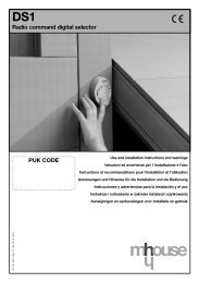
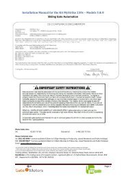
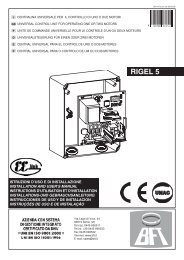
<strong>SB</strong>V/EN/112P Impianto 1 ingresso principale video N secondari video (max 10)<strong>SB</strong>V/EN/112P Video door entry system with 1 main video entrance panel N secondary video panels (10 max)<strong>SB</strong>V/EN/112P Installation 1 entrée principale vidéo N secondaires vidéo (10 max)<strong>SB</strong>V/EN/112P Anlage 1 Haupteingang Hauptvideo N Nebenvideo (max 10)11
VARIANTE A - VARIANT A - VARIANTE A - VARIANTE A• Impiego per usi vari del 2°pulsante del citofono2408W/A o 2410W(normalmente dedicatoalla chiamata centralino).• Using the 2° buttonof door entry phone2408W/A or 2410W forvarious purposes (normallydedicated to theswitchboard call).• Emploi pour usages différents2° bouton du combiné2408W/A ou 2410W(normalement dédié à l’appeldu standard).• Einsatz der Taste 2 derGegensprechanlageArt. 2408W/A oder 2410Wfür verschiedene Zwecke(normalerweise für den Rufder Zentrale bestimmt).VARIANTE B - VARIANT B - VARIANTE B - VARIANTE B• Impiego per usi vari delpulsante P1 (normalmentededicato alla chiamatacentralino) della staffa4614W/A.• Application for various usesof the P1 button (normallydedicated to the switchboardcall) of bracket 4614W/A.• Emploi pour usagesdifférents du bouton P1(normalement dédié àl’appel du standard) de labride 4614W/A.• Einsatz der Taste P1 desBügels 4614W/A fürverschiedene Zwecke(normalerweise für den Rufder Zentrale bestimmt).VARIANTE C - VARIANT C - VARIANTE C - VARIANTE C• Attivazione opzionaleaccensione interna sulpulsante P1 della staffa4614W/A (solo per impiantisenza centralino di portineriacon 1 o 2 ingressi).• Optional activation ofself-ignition on the P1 pushbutton of bracket 4614W/A(only for systems withoutCPS and with 1 or 2entrance units).• Activation en optionauto-allumage sur boutonP1 de la bride 4614W/A(seulement pour installationssans standard deconciergerie et avec1 ou 2 entrées).• Aktivierung wahlweiseEinschaltung von innen überSchalter P1 des Bügels4614W/A (nur für Anlagenohne Portierzentrale mit 1oder 2 Eingängen).VARIANTE D - VARIANT D - VARIANTE D - VARIANTE D• Attivazione opzionaleaccensione interna sulpulsante P2 della staffa4614W/A (solo per impianticon 1 o 2 ingressi ecentralino di portineria1998).• Optional activation ofself-ignition on the P2 pushbutton of bracket 4614W/A(only for systems with 1 or 2entrance units and CPS1998).• Activation en optionauto-allumage surbouton P2 de la bride4614W/A (seulement pourinstallations avec 1 ou 2entrées et standard deconciergerie 1998).• Aktivierung wahlweiseEinschaltung von innen überSchalter P2 des Bügels4614W/A (nur für Anlagenmit 1 oder 2 Eingängen undPortierzentrale 1998).VARIANTE E - VARIANT E - VARIANTE E - VARIANTE E• Utilizzo della chiamata dapiano sul citofono 2408W/Ao 2410W.• Use of the floor call on thehandsets art. 2408W/Aor 2410W.• Emploi de l’appel palier surle combiné art. 2408W/A ou2410W.• Verwendung desEtagenrufes auf derGegensprechanlageArt. 2408W/A oder 2410W.VARIANTE F - VARIANT F - VARIANTE F - VARIANTE F• Utilizzo della chiamata dapiano sulla staffa 4614W/A.• Use of the floor call on thebracket art. 4614W/A.• Emploi de l’appel palier surla bride art. 4614W/A.• Verwendung desEtagenrufes auf dem BügelArt. 4614W/A.Comelit Group S.p.A. - Via Don Arrigoni 5 - 24020 Rovetta S. Lorenzo BG Italy - tel. (+39) 0346 750 011 - fax (+39) 0346 71436www.comelit.it info@comelit.it commerciale.italia@comelit.it export.department@comelit.it15, Rue Jean Zay - 69800 Saint PriestTel 04 72 28 06 56 - Fax 04 72 28 83 29http://www.comelit.frE-mail: Comelit.NH@wanadoo.fr FPolderweg Oost 26 - 2973 An MolenaarsgraafTel 0184 64 91 58 - Fax 0184 64 01 58http://www.comelit.nlE-mail: info@comelit.nl NLChaussée de Ninove, 9001703 Schepdaal (Dilbeek)Tel 02 411 50 99 - Fax 02 411 50 97http://www.comelit.beE-mail: comelit@hotmail.com BUnit 8 Fiddlebridge Industrial EstateLemsford Road Hatfield Herts AL10 0DETel 017<strong>07</strong> 268826 - Fax 017<strong>07</strong> 266826http://www.comelitgroup.co.ukE-mail: info@comelitgroup.co.uk UK<strong>FT</strong>/<strong>SB</strong>/<strong>07</strong> - 2 a edizione 11/2003 - cod. 22590240