Boiler - Truma
Boiler - Truma
Boiler - Truma

Create successful ePaper yourself
Turn your PDF publications into a flip-book with our unique Google optimized e-Paper software.
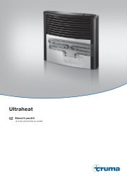
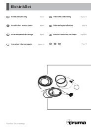
<strong>Boiler</strong> B 10 / B 14Symbols usedInstallation and repair are only to be carried out by anexpert. Always read and follow the operating instructionscarefully prior to starting any work!Non-compliance with installation instructions orincorrect installation can result in endangermentof persons and property.ApprovalSymbol indicates a possible hazard.Comment including information and tips.Liquid gas storage water heater(Special version B 10 EL, B 14 EL with additional electricheating 230 V, 850 W)Intended useThis appliance has been designed for the installation in caravans,mobile homes and other vehicles. It is not approved forinstallation in boats. Other forms of use are also possible followingconsultation with <strong>Truma</strong>.Information regarding boatsFor installation in boats <strong>Truma</strong> supplies the DVGW-tested boatwater heater.Installation instructionsDeclaration of conformityThe <strong>Truma</strong> water heater model has been tested and approvedthrough the DVGW and fulfils the EC gas appliance guidelines(90/396/EEC) as well as the associated EC guidelines. The CEIdent. Number is available for EU countries: CE-0085AP0038EC Type Approvale1 03 2604RegulationsGuarantee claims, warranty claims and acceptance of liabilitywill be ruled out in the event of the following:– modifications to the unit (including accessories),– modifications to the exhaust duct and the cowl,– failure to use original <strong>Truma</strong> parts as replacement partsand accessories,– failure to follow the installation and operating instructions.It also becomes illegal to use the appliance, and in somecountries this even makes it illegal to use the vehicle.In-vehicle installations must comply with the technical andadministrative regulations of the respective country of use(e.g. EN 1949 for vehicles). The national regulations and rules(e.g. DVGW work sheet G 607 in Germany) must be compliedwith.In other countries always observe the respectively validregulations.More information on the regulations in the relevant destinationcountries can be requested from our foreign representatives(see <strong>Truma</strong> Service Booklet or www.truma.com).Choice of locationAlways install the appliance in such a way that it is easilyaccessible for service work at all times and can be easily removedand installed.Locate the heater in such a way that the cowl can be mountedon the outside on a surface which is as straight and smoothas possible.This outside surface must be exposed to wind from alldirections and, if possible, there should be no trim stripsor covers in this area, mount heater on an appropriate base,if necessary.Fig. HThe wall cowl must be attached so that no tank supports ortank ventilation openings are found within 500 mm (R). In addition,no air discharge apertures for the living area or windowopenings may be located with 300 mm (R) of it.When fitting the cowl within the marked area below ornext to a window that must be open, an electrical windowswitch (part no. 34000-85800) must be installed. The gasunit must automatically switch itself off using the <strong>Truma</strong> automaticshut-off facility if the window is opened (Accessories,part no. 70020-00800).Installation of the water heaterPosition template for cowl opening on the inside of the wall.A = bottom edge of heaterB = lateral edge of heaterDrill 4 holes (C) with 10 mm dia. through the wall. Drill hole (E)with 15 mm dia. for condensation pipe (also possible from theoutside = F).Position template on the outside of the wall. The markings (C)must be above the through-holes. Saw cut-out section forcowl (D) 92 x 168 mm.If the distance between outside wall and heater is more than35 mm you must use the cowl extension VBO 2 (part no.70131-00) with an additional length of 50 mm. Saw out100 x 176 mm along the dashed line.If there are any cavities in the area of the cowl (fig. A: 1), packthese with pieces of wood so as to be able to tighten thescrews.Cut out trim strips or such on the vehicle or place supportsbeneath them so as to make the cowl lie flat.Place a support beneath the heater if the walls are sloping. Anangle of inclination of 10 degrees is not to be exceeded.Fig. AInsert heater with cowl body (3) through the cowl opening (1),allow approx. 5 mm to project out of the wall. Mount sealingframe (4 – the anti-torsion device ensures correct fitting!).Pre-drill holes for the 6 fastening bolts (5).Remove sealing frame (4) and coat with plastic sealant on theside facing the vehicle – do not use silicone!The sealing frame must be well sealed with respect tothe front sides and the cross bars of the cowl part (3) aswell as towards the outside wall!Fasten sealing frame (4) to the cowl part using 4 selfcuttingscrews (7 – torque 3.5 Nm).Seal the gap between the hole (2) and the condensationtube (10) with plastic sealant – do not use silicone!Mount the grille (8). Press the entire cowl assembly onto thevehicle wall and fasten with 6 screws (5).6