5. Einbau und Montage - Kessel
5. Einbau und Montage - Kessel
5. Einbau und Montage - Kessel

Create successful ePaper yourself
Turn your PDF publications into a flip-book with our unique Google optimized e-Paper software.
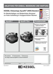
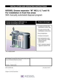
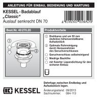
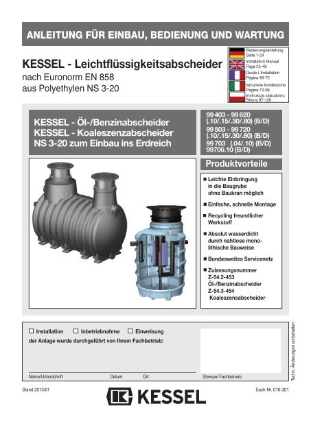
ANLEITUNG FÜR EINBAU, BEDIENUNG UND WARTUNGKESSEL - Leichtflüssigkeitsabscheidernach Euronorm EN 858aus Polyethylen NS 3-20BedienungsanleitungSeite 1-24Installation ManualPage 25-48Guide L´InstallationPagina 49-72Istruzione InstallazionePagina 73-96Instrukcja zabudowy,Strona 97-120KESSEL - Öl-/BenzinabscheiderKESSEL - KoaleszenzabscheiderNS 3-20 zum <strong>Einbau</strong> ins Erdreich99 403 - 99 620(.10/.15/.30/.80) (B/D)99 503 - 99 720(.10/.15/.30/.80) (B/D)99 703 (.04/.10) (B/D)99706.10 (B/D)ProduktvorteileLeichte Einbringungin die Baugrubeohne Baukran möglichEinfache, schnelle <strong>Montage</strong>Recycling fre<strong>und</strong>licherWerkstoffAbsolut wasserdichtdurch nahtlose mono -lithische BauweiseB<strong>und</strong>esweites ServicenetzZulassungsnummerZ-54.2-453Öl-/BenzinabscheiderZ-54.3-454KoaleszensabscheiderInstallation Inbetriebnahme Einweisungder Anlage wurde durchgeführt von Ihrem Fachbetrieb:Name/Unterschrift Datum OrtStempel FachbetriebTechn. Änderungen vorbehaltenStand 2013/01Sach-Nr. 010-301
1. SicherheitshinweiseDas Personal für <strong>Einbau</strong>, <strong>Montage</strong>, Bedienung, Wartung <strong>und</strong> Reparatur muß die entsprechendeQualifikation für diese Arbeiten aufweisen. Verantwortungsbereich, Zuständigkeit<strong>und</strong> die Überwachung des Personals müssen durch den Betreiber genau geregelt sein.Die Betriebssicherheit der gelieferten Anlage ist nur bei bestimmungsgemäßer Verwendunggewährleistet. Die Grenzwerte der technischen Daten dürfen auf keinen Fall überschrittenwerden.Bei <strong>Einbau</strong>, <strong>Montage</strong>, Bedienung, Wartung <strong>und</strong> Reparatur der Anlage sind die Unfallverhütungsvorschriften<strong>und</strong> die in Frage kommenden Normen <strong>und</strong> Richtlinien zu beachten!Dies sind u.a.:• Unfallverhütungsvorschriften- Bauarbeiten BGV C22- Abwassertechnische Anlagen GUV-V C5• Sicherheitsregeln für Arbeiten in umschlossenen Räumen von abwassertechnischenAnlagen GUV-R 126• Umgang mit biologischen Arbeitsstoffen in abwassertechnischen Anlagen GUV-R 145• Richtlinien für Arbeiten in Behältern <strong>und</strong> engen Räumen BGR 117• Normen- Baugruben <strong>und</strong> Gräben - Böschungen, Verbau, Arbeitsraumbreiten DIN 4124- Verlegung <strong>und</strong> Prüfung von Abwasserleitungen <strong>und</strong> -kanälen DIN EN 1610• Arbeitshilfe für Sicherheit <strong>und</strong> Ges<strong>und</strong>heitsschutz in abwassertechnischen Anlagen.SPEZIFISCHEGEFÄHRDUNGEN!• Gefahren durch Gase <strong>und</strong> Dämpfe wie Erstickungsgefahr, Vergiftungsgefahr <strong>und</strong> Explosionsgefahr• Absturzgefahr• Ertrinkungsgefahr• Keimbelastung <strong>und</strong> fäkalienhaltige Abwässer• Hohe physische <strong>und</strong> psychische Belastungen bei Arbeiten in tiefen, engen oder dunklenRäumen• <strong>und</strong> weitereWARNUNG !Bei Nichtbeachtung der Bedienungsanleitung können erhebliche Sachschäden, Körperverletzungenoder tödliche Unfälle die Folge sein.ACHTUNG !Die Anlage stellt eine Komponente einer Gesamtanlage dar. Beachten Sie deshalb auchdie Bedienungsanleitungen der Gesamtanlage <strong>und</strong> der einzelnen Komponenten. Bei jeder<strong>Montage</strong>, Wartung, Inspektion <strong>und</strong> Reparatur an einer der Komponenten ist immer die Gesamtanlageaußer Betrieb zu setzen <strong>und</strong> gegen Wiederinbetriebnahme zu sichern.Umbau oder Veränderungen der Anlage sind nur in Absprache mit dem Hersteller zu tätigen.Originalersatzteile <strong>und</strong> vom Hersteller zugelassenes Zubehör dienen der Sicherheit.Die Verwendung anderer Teile kann die Haftung für die daraus entstehenden Folgen aufheben.2
Inhaltsverzeichnis1. Sicherheitshinweise ................................................................................. Seite 22. Einsatzbereich 2.1 Einsatzbereich.......................................................... Seite 42.2 Anlagenbeschreibung ............................................. Seite 52.3 Funktionsbeschreibung............................................ Seite 53. Technische Daten 3.1 <strong>Einbau</strong>vorschlag Öl-/Benzinabscheider............................. Seite 63.2 Maßzeichnung Öl-/Benzinabscheider................................ Seite 63.3 <strong>Einbau</strong>vorschlag Koaleszenzabscheider Zisterne................. Seite 73.4 Maßzeichnung Koaleszenzabscheider Zisterne.................... Seite 73.5 Abbildung Koaleszenzabscheider Schacht LW 1000, NS 3 ........ Seite 83.6 Maßzeichnung Koaleszenzabscheider Schacht LW 1000, NS 3.. Seite 83.7 Maßzeichnung Koaleszenzabscheider Schacht LW 1000, NS 6.. Seite 84. Verpackung, Transport 4.1 Verpackung............................................................... Seite 9<strong>und</strong> Lagerung 4.2 Transport .................................................................. Seite 94.3 Lagerung.................................................................. Seite 9<strong>5.</strong> <strong>Einbau</strong> <strong>und</strong> <strong>Montage</strong> <strong>5.</strong>1 <strong>Einbau</strong>voraussetzungen........................................... Seite 10<strong>5.</strong>2 Verfüllmaterial .......................................................... Seite 11<strong>5.</strong>3 Baugrube.................................................................. Seite 11<strong>5.</strong>4 Prüfungen vor dem <strong>Einbau</strong> ...................................... Seite 11<strong>5.</strong>5 <strong>Einbau</strong>...................................................................... Seite 11‘<strong>5.</strong>6 Öl- <strong>und</strong> Schlammabsaugung.................................... Seite 136. Inbetriebnahme 6.1 Anlage in Betriebsbereitschaft setzen...................... Seite 156.2 Einweisung / Übergabe ............................................ Seite 156.3 Übergabeprotokoll.................................................... Seite 157. Entsorgung .............................................................................................. Seite 168. Eigenkontrolle, Wartung <strong>und</strong> Überprüfung .............................................................................................. Seite 189. Ersatzteile <strong>und</strong> Zubehör .............................................................................................. Seite 2010. Gewährleistung .............................................................................................. Seite 2111. Anlagenpaß/Werksabnahme .............................................................................................. Seite 22Übergabeprotokoll .............................................................................................. Seite 233
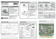
2. EinsatzbereichIn den Fällen a) bis d) ist das Ablaufwasser der Abscheiderzur Einleitung in die öffentlichen Entwässerungsanlagen bestimmt.Soweit das Ablaufwasser in ein Gewässer eingeleitet werdensoll, ist dies im Einzelfall nur möglich nach Klärung der Zulässigkeiteiner solchen Einleitung bwz. der ggf. erforderlichenzusätzlichen Anforderungen mit der örtlich zuständigen Wasserbehörde.Abscheider, die im Fall d) eingesetzt werden, sind in Anlagenzur Begrenzung von Kohlenwasserstoffen in mineralölhaltigemAbwasser im Sinne von Teil E Absatz 2 des Anhangs 49der Abwasserverordnung.Der in den Fällen c) <strong>und</strong> d) wasserrechtlich geforderte Wertfür Kohlenwasserstoffe von 20 mg/l gilt als eingehalten.2.2 AnlagenbeschreibungDie Abbildung zeigt einen erdeingebauten Benzinabscheider-ZisterneKlasse A/B. Ablaufstelle ohne Geruchsverschluß Leichtflüssigkeitsabscheider Zulauf mit Geruchsverschluß Ablauf mit selbsttätigen Abschluß Führungsrohr Schwimmer Aufsatzstück Abdeckung Probenahmeschacht Rückstausicherung2.3 FunktionsbeschreibungDie Abscheider bewirken eine Trennung des Abwassers vonLeichtflüssigkeiten <strong>und</strong> Schlamm aufgr<strong>und</strong> der Schwerkraft.Unter Leichtflüssigkeiten versteht man Flüssigkeiten mineralischenUrsprungs mit einer Dichte ≤ 0,95 g/cm 3 , die im Wassernicht oder nur gering löslich <strong>und</strong> unverseifbar sind. Nichtdazu gehören stabile Emulsionen, Fette <strong>und</strong> Öle pflanzlichenoder tierischen Ursprungs. Leichtflüssigkeiten schwimmenim Abscheideraum auf <strong>und</strong> sammeln sich an der Oberflächean. Schlämme, die schwerer sind als Wasser, sinken zuBoden <strong>und</strong> bilden eine Schlammschicht.Koaleszenzabscheider funktionieren wie Öl-/Benzinabscheidernach dem Schwerkraftprinzip. Zur Erhöhung der Abscheideleistungbefindet sich zusätzlich noch ein Koaleszenzeinsatzim Behälter. Dieser zylinderförmige Einsatz hat zweiFunktionen. Zum einen beeinflußt er die Strömung im Abscheider,zum anderen „filtert“ er das gesamte Abwasserdurch das Koaleszenzmaterial.Wird dieses Filtergewebe von ölhaltigem Abwasser durchströmt,lagern sich feinste, über die Schwerkraft nicht mehrabscheidbare, Öltröpfchen an das Koaleszenzmaterial an<strong>und</strong> vereinigen sich dort zu großen Öltropfen. Haben dieseeine auftriebssichere Größe erreicht, lösen sie sich vom Filtermaterial<strong>und</strong> steigen zur Oberfläche auf.Leichtflüssigkeitsabscheider sind serienmäßig mit einemselbsttätigen Verschluß ausgestattet.Wird die maximale Ölspeichermenge überschritten, verschließtdiese Einrichtung den Ablauf zur Kanalisation. DerAustritt von Leichtflüssigkeiten in die Kanalisation wird verhindert.Diese Sicherung besteht aus einem mit Wasser gefülltenFührungsrohr in dem sich ein Schwimmer befindet.Der Schwimmer ist so tariert, dass er im Wasser schwimmt<strong>und</strong> in der Leichflüssigkeit (bis zu einer Dichte von 0,95 g/cm 3 )sinkt. Wird die maximale Ölspeichermenge erreicht, gelangtÖl durch seitliche Öffnungen in das Schwimmer-Führungsrohr.Der Schwimmer sinkt dann nach unten <strong>und</strong> verschließtzuverlässig den Ablauf des Abscheiders.Der selbsttätige Verschluss eines Abscheiders ist eine „Notbremse“.Löst er im Havariefall aus, ist der Abscheider außerBetrieb zu nehmen <strong>und</strong> zu warten.5
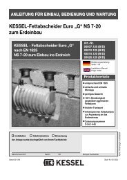
3. Technische Daten3.1 <strong>Einbau</strong>vorschlag: KESSEL-Öl-/Benzinabscheider-ZisterneAbbildung zeigt KESSEL-Öl-/Benzinabscheider-Zisterne Klasse II mit Abdeckung Klasse B <strong>und</strong> Probenahmeschacht3.2 MaßzeichnungDN 150: T-TEÜ = 155 mmDN 200: T-TEÜ = 180 mmT-TEÜ = Tiefe ErdüberdeckungKlasse D: 700 mm ≤ TEÜ ≤ 1.500 mmKlasse A/B: 700 mm ≤ TEÜ ≤ 1.800 mm2020 4000 600L max(mm)3080308035353535429542953860386035353535429542954295429599620.80B 429599620.80D 42956
3. Technische Daten3.3 <strong>Einbau</strong>vorschlag: KESSEL-Koaleszenzabscheider ZisterneAbbildung zeigt KESSEL-Koaleszenzabscheider-Zisterne Klasse I mit Abdeckung Klasse B <strong>und</strong> Probenahmeschacht3.4 Maßzeichnung ZisterneDN 150: T-TEÜ = 155 mmDN 200: T-TEÜ = 180 mmT-TEÜ = Tiefe ErdüberdeckungKlasse D: 700 mm ≤ TEÜ ≤ 1.500 mmKlasse A/B: 700 mm ≤ TEÜ ≤ 1.800 mmL max(mm)308030803535353542954295386038603535353542954295429542957
3. Technische Daten3.5 Abbildung: KESSEL-KoaleszenzabscheiderSchacht LW 1000, NS 33.6 Maßzeichnung KESSEL-KoaleszenzabscheiderSchacht LW 1000, NS 3NSDurchmesserØ3 800 100 1100 Ø 545 995 1105 1055 790 200 110 175 B 99703.04B3 800 100 1100 Ø 545 995 1105 1055 790 200 110 205 D 99703.04D3 1600 100 1100 Ø 545 995 1605 1555 1390 200 110 190 B 99703.10B3 1600 100 1100 Ø 545 995 1605 1555 1390 200 110 220 D 99703.10Dø3.7 Maßzeichnung KESSEL-Koaleszenzabscheider LW 1000, NS 6 (mit vorgeschaltetem Schlammfang)øDurchmesserNSØ6 1000 150 1100 Ø 560 1010 1090 1020 1580 200 110 305 B 99706.10B6 1000 150 1100 Ø 560 1010 1090 1020 1580 200 110 338 D 99706.10D8
4. Verpackung, Transport <strong>und</strong> LagerungDas Kapitel Sicherheitshinweise ist zu beachten!4.1 VerpackungEine Verpackung der Behälter zum Zwecke des Transportsbzw. der Lagerung ist bei Beachtung der nachfolgendenPunkte nicht notwendig.Hinweis: Der Eintrag von Fremdkörpern (Schmutz, Staubetc.) in den Abscheider ist zu vermeiden. Ggf. sind an allenÖffnungen Abdeckungen anzubringen.4.2 Transportl Der Transport ist nur von solchen Firmen durchzuführen,die über fachliche Erfahrungen, geeignete Geräte, Einrichtungen<strong>und</strong> Transportmittel sowie ausreichend geschultesPersonal verfügen.l Die Behälter müssen so transportiert werden, daß sienicht unzulässig belastet werden <strong>und</strong> daß eine Lageveränderungwährend des Transports ausgeschlossen ist. Im Falleeiner Verspannung ist diese so vorzunehmen, daß eine Beschädigungder Behälter ausgeschlossen ist (z.B. Verwendungvon Gewebegurten, Hanfseilen). Die Verwendung vonDrahtseilen oder Ketten ist nicht zulässig.Abbildung zeigt ZisterneAbbildung zeigt Zisternel Die Behälter dürfen nicht freistehend <strong>und</strong> ungesichert aufoffenen Ladeflächen von Transportfahrzeugen transportiertwerden. Die mit Sicherungsschrauben fixierten Bauzeitschutzabdeckungendürfen erst kurz vor dem <strong>Einbau</strong> entferntwerden.4.3 LagerungSollte eine Lagerung der Behälter vor dem <strong>Einbau</strong> erforderlichsein, so darf diese nur kurzzeitig <strong>und</strong> auf ebenem, vonscharfkantigen Gegenständen befreitem Untergr<strong>und</strong> geschehen.Bei Lagerung im Freien sind die Behälter gegenBeschädigung, Sturmeinwirkung <strong>und</strong> Verschmutzung zuschützen.l Beim Abheben, Verfahren <strong>und</strong> Absetzen der Behältermüssen stoßartige Beanspruchungen vermieden werden.Kommt ein Gabelstapler zum Einsatz, müssen während derFahrt mit dem Gabelstapler die Behälter gesichert werden.Ein Rollen oder Schleifen der Behälter über den Untergr<strong>und</strong>ist nicht zulässig.l Die Behälter sind gegen unzulässige Lageveränderungenwährend der Beförderung zu sichern. Durch die Art der Befestigungdürfen die Behälter nicht beschädigt werden.Abbildung zeigt Zisterne9
<strong>5.</strong> <strong>Einbau</strong> <strong>und</strong> <strong>Montage</strong>Während der Zwischenlagerung des Abscheiders so wiebis zum Abschluß der <strong>Einbau</strong>arbeiten müssen an derBaustelle geeignete Sicherungsmaßnahmen getroffenwerden, um Unfälle <strong>und</strong> Beschädigungen des Leichtflüssigkeitabscheiderszu verhindern.Das Kapitel Sicherheitshinweise ist zu beachten!<strong>5.</strong>1 <strong>Einbau</strong>voraussetzungenDer <strong>Einbau</strong> ist nur von solchen Firmen durchzuführen, dieüber fachliche Erfahrungen, geeignete Geräte <strong>und</strong> Einrichtungensowie ausreichend geschultes Personal verfügen.Eine Erfassung der Bodenbeschaffenheit im Hinblick auf diebautechnische Eignung muß vorgenommen sein (Bodenklassifikationfür bautechnische Zwecke DIN 18196). Dermaximal auftretende Gr<strong>und</strong>wasserstand muß festgestelltsein. Der Gr<strong>und</strong>wasserstand darf das Niveau des Ablaufesnicht überschreiten. Eine ausreichende Ableitung (Drainage)von Sickerwässern ist bei wasser<strong>und</strong>urchlässigen Bödenzwingend notwendig. Die auftretenden Belastungsarten wiemax. Verkehrslasten <strong>und</strong> <strong>Einbau</strong>tiefe müssen abgeklärt sein.Die Abscheider zum Erdeinbau sollten außerhalb der Gebäudeso nah wie möglich an den Abläufen eingebaut werden.Gegebenenfalls sind die Anschlußleitungen der Zuläufezum Abscheider wärmegedämmt oder beheizt zu verlegen.Unter Verwendung von teleskopischen Aufsatzstückenwird die erforderliche frostfreie <strong>Einbau</strong>tiefe erreicht sowie dieeinfache Anpassung an Zu- <strong>und</strong> Ablaufleitung (Kanal) hergestellt.Die Abdeckungen für die Belastungsklassen A / B<strong>und</strong> D sind unverschraubt <strong>und</strong> entsprechen der EN 124.Abscheideranlagen müssen nahe der Anfallstelle der Leichtflüssigkeiteneingebaut werden. Sie müssen für die Reinigung<strong>und</strong> Wartung leicht zugänglich sein.Der Einsatz von verriegelten oder belüfteten Abdeckungenist verboten.Pump- oder Hebeanlagen dürfen im Zulauf vor dem Abscheidernicht eingebaut werden. Sind diese notwendig, somüssen sie nach dem Abscheider installiert werden.KESSEL empfiehlt für den sicheren Betrieb der Anlage, bauseitseinen Überstand <strong>und</strong> zusätzlich die <strong>Montage</strong> einerWarnanlage vorzusehen. Notwendige <strong>Montage</strong>voraussetzungensollten vor dem Verfüllen der Baugrube geschaffenwerden.Abscheideranlagen sind so einzubauen, dass die Oberkanteder Abdeckungen ausreichend hoch gegenüber demmaßgebenden Niveau der zu entwässernden Fläche angeordnetsind (siehe Bild 1).Als maßgebendes Niveau gilt die höchstmögliche Regenwasserstauhöhe,wenn Schmutzwasser <strong>und</strong> Regenwasserzusammengeleitet werden.Wenn nur Schmutzwasser eingeleitet wird, gilt die Oberkantedes am niedrigsten angeschlossenen Ablaufs als maßgebendesNiveau. Der notwendige Überstand ist abhängig vonder Nenngröße des Abscheiders (siehe Kapitel TechnischeDaten).Kann diese Überhöhung nicht eingehalten werden, so musseine Warneinrichtung für Leichtflüssigkeiten eingebaut werden.Betriebsbereite AbscheideranlageEntwässernde FlächeÜberstand/ÜberhöhungBild 1Oberkante AbdeckungAbbildung zeigt ZisterneLeichtflüssigkeitsabscheider sind bauseits vor Rückstau ausdem Kanal zu schützen.KESSEL empfiehlt folgende Schutzvorkehrungen:Ablaufstelle Abscheider Rückstauschutzinnerhalb eines Überstand RückstauverschlussGebäudesvorhandeninnerhalb eines kein RückstauverschlussGebäudesÜberstandaußerhalb eines Überstand RückstauverschlussGebäudesvorhandenaußerhalb eines kein HebeanlageGebäudesÜberstandBitte beachten:Witterungsbedingte Einflüsse oder Abkühlung der Behälterwährend der Verbauphase (durch Befüllen mit kaltem Wasser),können bei Zisternen, erdeingebauten Abscheidern <strong>und</strong>Kleinkläranlagen zu Maßabweichungen von den Katalogangabenführen. Bitte prüfen Sie daher vor Verbau insbesonderedie Höhenangaben auf ihr tatsächliches Maß.Der Flüssigkeitsspiegel im Abscheider liegt wegen des Dichteunterschiedsvon Leichtflüssigkeit zu Wasser immer höherals der Wasserspiegel im Entwässerungssystem.10
<strong>5.</strong> <strong>Einbau</strong> <strong>und</strong> <strong>Montage</strong>Ist die Baugrube bis zur Unterkante der Zu- <strong>und</strong> Ablauflei -tungs anschlüsse aufgefüllt <strong>und</strong> verdichtet, sind die Zu-/Ab laufleitungen frostfrei zu verlegen <strong>und</strong> anzuschließen.Hinweis für Warnanlage: Im Zuge der Erdarbeiten Verbindungskabeloder Leerrohr verlegen.l Probenahmeschacht anschließen.Probenahmeeinrichtungen sind in Fließrichtung unmittelbarhinter dem Abscheider anzuordnen. Die Probenahmeeinrichtungder Abscheideranlage muß frei zugänglich <strong>und</strong> soangeordnet sein, daß nur Abwasser entnommen wird, dasden Abscheider durchflossen hat.l Lippendichtung DN 600 in der Nut im Dom einlegen <strong>und</strong>einfettenteleskopischesAufsatzstückl ggf. Warnanlagenleerrohr anschließenDie Verbindungsstrecke zwischen Abscheider <strong>und</strong> Steuereinheitist möglichst kurz zu halten.Unnötige Richtungsänderungen, insbesondere solche mitAbwinkelungen über 45° sind zu vermeiden.Das Kabelleerrohr sollte ein stetiges Gefälle zum Abscheideraufweisen.Kondenswasserbildung innerhalb der Kabellehrrohres kanndurch einen luftdichten Abschluss des Leerrohres auf derSeite der Steuereinheit, minimiert werden. Für eventuellenachträgliche Kabelverlegungen kann ein Kabeldurchzugsdrahtmit eingelegt werden.76LippendichtungDN 600Das Aufsatzstückmuss zwischen100 mm <strong>und</strong> 200mm Mindesteinstecktiefegekürztwerden.Mindesteinstecktiefe100 mmBehälterdom13(1) KESSEL-Leichtflüssigkeitsabscheider(2) Schichtdicken-Sensor(3) Aufstau-Sensor(4) Steuereinheit(5) Gehäuse für Wandmontage(6) wasserdichte Kabelverbindung(7) Befestigungsset(8) Leerrohrverschluß5842l Das teleskopische KESSEL-Aufsatzstück muss soweitgekürzt werden, dass alle <strong>Einbau</strong>teile problemlos zu wartensind. Vor dem Einstecken 15° anfasen, um Beschädigungenan der Dichtung zu vermeiden. Anschließend das Aufsatzstückin die Öffnung des Abscheiders einstecken <strong>und</strong> in diege wünschte Position bringen. Mit Hilfe des vorhandenenKlemm ringes kann nun das Aufsatzstück in der gewünschtenPosition (Ausrichtung an der Geländeoberkante) fixiertwerden. Die Feinjustierung auf die endgültige Höhe erfolgtdann mittels der Stellschrauben. Bodenneigungen könnendurch das stufenlos höhenverstellbare <strong>und</strong> neigbare Aufsatzstückleicht ausgeglichen werden. Das Aufsatzstück istausreichend zu unterfüttern <strong>und</strong> mittels eines Flachbettrüttlers<strong>und</strong> einer auf das Aufsatzstück aufgelegten Stahlplatteeinzurütteln.Für größere <strong>Einbau</strong>tiefen ist das dafür vorgesehene spe -zielle KESSEL-Zwischenstück (Art.-Nr. 917402), Aufbau -höhe 400 mm zu verwenden.l restliche VerfüllungFür den <strong>Einbau</strong> in LKW-befahrene Bereiche (AbdeckungKlasse D) muss als oberste Schicht eine Stahlbetonplattevorgesehen werden. Ein zugehöriger Schalungs- <strong>und</strong> Bewehrungsplanist bei KESSEL erhältlich.12
<strong>5.</strong> <strong>Einbau</strong> <strong>und</strong> <strong>Montage</strong>Bohrung fürDurchführungssset180↕30°30°45°Pinorreks gemäß Zeichnung mit beiliegenden Edelstahlschraubenim Aufsatzstück montieren.Für die Bohrung darf nur ein Bohrer Ø 3,5 mm verwendetwerden. Verwenden Sie den Pinorrek als Bohrschablone.Storzkupplung am Schlauchende montieren <strong>und</strong> mitSchlauchschelle fixieren.Schlauch mit Storzkupplung nach oben in Pinorrek einhängen,bis zur Absaugeeinrichtung führen <strong>und</strong> geeignet ablängen.Schlauch <strong>und</strong> Absaugeeinrichtung verbinden <strong>und</strong> mitSchlauchschelle fixieren.Bei geschlossener Abdeckung darf diese die Storzkupplungnicht berühren.132 6 7Zum Verbau der Kabeldurchführungist der Behälter miteiner Sägeglocke mit 60 mmanzubohren.4Abbildung zeigt Zisterne<strong>5.</strong>6 Öl- <strong>und</strong> Schlammabsaugung(für Schacht LW 1000 nur auf Anfrage)Bei einer normalen Entsorgung wird der Schlauch vom Saugewagenin den Leichtflüssigkeitsabscheider gehalten <strong>und</strong>der gesamte Inhalt abgepumpt.Die Menge an Leichtflüssigkeit ist aber deutlich geringer alsdas Gesamtvolumen des Abscheiders. Mit der Ölabsaugeeinrichtungwird hier Abhilfe geschaffen.Zur Entsorgung der Leichtflüssigkeit wird der Saugschlauchan die Ölabsaugeeinrichtung gekoppelt. Damit kann durchden Saugewagen nur noch das Volumen entsorgt werden,das der maximalen Leichtflüssigkeitsmenge entspricht.Das bedeutet eine deutliche Reduzierung der Entsorgungsmenge.Das alles bringt eine Zeitersparnis bei der Entsorgung,niedrige Entsorgungskosten sowie ein Schonen der<strong>Einbau</strong>teile im Abscheider. Analog der Ölabsaugeeinrichtungkann durch die Schlammabsaugeeinrichtung die Entsorgungsmengeauch hier deutlich reduziert werden.Insbesondere für Betriebe mit einem hohen Schlammaufkommenist das von Vorteil. Selbstverständlich kann durchdie Schlammabsaugevorrichtung auch der gesamte Abscheiderentleert werden.Kommen beide Einrichtungen bei der Entsorgung zum Einsatz,muss sichergestellt werden, dass zuerst das Öl <strong>und</strong>dann der Schlamm entsorgt wird.Die Arretiervorrichtung wird am Zulauf gemäß Zeichnung mitder Rohrschelle befestigt.Die Ölabsaugung an der Arretiervorrichtung montieren, aufdas Höhenmaß x (siehe Tabelle) einstellen <strong>und</strong> fixieren.Die Schlammabsaugung an der Arretiervorrichtung montieren,bis zum Boden führen <strong>und</strong> dann fixieren.5Innenseite(1) Kabel zu den Sonden(2) Kaberverschraubungene(3) Überwurfmutter(4) DurchgangsdichtungArretiervorrichtungAußenseite(5) Leerrohrverschluß(6) Durchgangsrohr(7) Leerrohr13
<strong>5.</strong> <strong>Einbau</strong> <strong>und</strong> <strong>Montage</strong>LeichtflüssigkeitsabscheiderArt.-Nr.:99403.10B 99403.10BEX 99503.10B 99503.10BEX99403.10D 99403.10DEX 99503.10D 99503.10DEX99610.15B 99610.15BEX 99710.15B 99710.15BEX99610.15D 99610.15DEX 99710.15D 99710.15DEX99606.30B 99606.30BEX 99706.30B 99706.30BEX99606.30D 99606.30DEX 99706.30D 99706.30DEX99610.30B 99610.30BEX 99710.30B 99710.30BEX99610.30D 99610.30DEX 99710.30D 99710.30DEX99606.80B 99606.80BEX 99706.80B 99706.80BEX99606.80D 99606.80DEX 99706.80D 99706.80DEX99610.80B 99610.80BEX 99710.80B 99710.80BEX99610.80D 99610.80DEX 99710.80D 99710.80DEX9961<strong>5.</strong>80B 9961<strong>5.</strong>80BEX 9971<strong>5.</strong>80B 9971<strong>5.</strong>80BEX 99620.80B9961<strong>5.</strong>80D 9961<strong>5.</strong>80DEX 9971<strong>5.</strong>80D 9971<strong>5.</strong>80DEX 99620.80D99703.04B99703.04D99703.10B99703.10D99706.10B99706.10DAbstand X derÖlabsaugung zum Behälterboden950 mm1450 mmauf Anfrageauf Anfrage14
6. InbetriebnahmeDas Kapitel Sicherheitshinweise ist zu beachten!6.1 Anlage in Betriebsbereitschaft setzenZu- <strong>und</strong> Ablaufleitung sind zu spülen.Die Anlage ist vor der Zuführung von mineralölhaltigem Abwasser➤ zu entleeren, vollständig zu reinigen <strong>und</strong> wieder zu befüllen.➤ Den Schwimmer im Führungsrohr anheben <strong>und</strong>Schwimmlage <strong>und</strong> Beweglichkeit prüfen. Bei Koaleszenzabscheider:Koaleszenzeinsatz in vorgeseheneFüh run g einschieben.6.2 Einweisung / ÜbergabeDie Einweisung ist durch einen qualifizierten Fachbetriebdurchzuführen.2. Einweisung:➤ Kontrolle der Anlage auf Dichtheit, Transport- <strong>und</strong> <strong>Montage</strong>schädensowie Prüfung der Leitungsverbindungen➤ Information zur Entsorgung (Absaugung)➤ Praktische Vorführung der Bedienungsmöglichkeiten3. Dokumentation➤ Übergabe der <strong>Einbau</strong>- <strong>und</strong> Bedienungsanleitung➤ Erstellung des Übergabeprotokolls.6.3 ÜbergabeprotokollDas Übergabeprotokoll ist vollständig auszufüllen <strong>und</strong> vom Abnahmeberechtigten<strong>und</strong> Anlagenbetreiber zu unterzeichnen.1. Folgende Personen sollten bei der Übergabe anwesendsein:➤ Abnahmeberechtigter des Bauherrn➤ FachbetriebFerner empfehlen wir die Teilnahme des➤ Bedienungspersonals➤ Entsorgungsunternehmens15
7. EntsorgungEntleerungsintervalle:Die im Abscheider zurückgehaltene Leichtflüssigkeit ist spätestenszu entnehmen, wenn die Menge der abgeschiedenenLeichtflüssigkeit 80% der maximalen Speichermengeerreicht hat, oder das Rückhaltevolumen unterschrittenwurde. Bei Abscheidern, die gleichzeitig oder ausschließlichzur Absicherung von Anlagen oder Flächen dienen, in bzw.auf denen mit Leichtflüssigkeiten umgegangen wird (z.B.Betankungsflächen), ist ergänzend das nach den landesrechtlichenBestimmungen erforderliche Rückhaltevolumenvorzuhalten. Die abgeschiedene Leichtflüssigkeit ist daherbei einer Unterschreitung dieses Rückhaltevolumens auchdann zu entnehmen, wenn die Menge der abgeschiedenenLeichtflüssigkeiten 80 % der Speichermenge noch nicht erreichthat.Die Entsorgung des im Schlammfang enthaltenen Schlammesmuss spätestens dann erfolgen, wenn die abgeschiedeneSchlammmenge die Hälfte des Schlammfangvolumensgefüllt hat.Aus diesem Gr<strong>und</strong>e sollte mit einem Entsorgungsfachbetriebein Entsorgungsvertrag abgeschlossen werden. DieEntsorgungsarbeiten sind möglichst während der Zeitendurchzuführen, in denen der Betrieb ruht.Zu erwartende Entsorgungsvolumen in Abhängigkeit desFüllungsgrades können anhand der folgenden Tabelle abgeschätztwerden.Die darin enthaltenden Angaben verstehen sich als ca.-Angabenzur Abschätzung der Mengen im Zuge der Beauftragungeines Entsorgungsfachbetriebes.Achtung: Nur eine rechtzeitige Entsorgung der Anlagege währleistet eine richtige Funktion.16
7. EntsorgungLeichtflüssigkeitsabscheider Schlamm LeichtflüssigkeitArt.-Nr.: 1) gemessene Entsorgungs- 2) gemessene Entsorgungs-Füllgrad Schichtdicke volumen Füllgrad Schichtdicke volumenin % in mm in Liter in % in mm in Liter99403.10B 99403.10BEX 99503.10B 99503.10BEX 50 650 1000 100 131 18799403.10D 99403.10DEX 99503.10D 99503.10DEX 40 530 800 80 105 15030 430 600 60 79 11220 330 400 40 52 7510 210 200 20 26 3799610.15B 99610.15BEX 99710.15B 99710.15BEX 50 650 1500 100 131 26299610.15D 99610.15DEX 99710.15D 99710.15DEX 40 550 1200 80 105 21030 450 900 60 79 15720 340 600 40 52 10510 220 300 20 26 5299606.30B 99606.30BEX 99706.30B 99706.30BEX 50 1100 3000 100 138 26599606.30D 99606.30DEX 99706.30D 99706.30DEX 40 930 2400 80 110 21299610.30B 99610.30BEX 99710.30B 99710.30BEX 30 760 1800 60 83 15999610.30D 99610.30DEX 99710.30D 99710.30DEX 20 580 1200 40 55 10610 370 600 20 28 5399606.80B 99606.80BEX 99706.80B 99706.80BEX 50 1100 4000 100 138 38099606.80D 99606.80DEX 99706.80D 99706.80DEX 40 910 3200 80 110 30499610.80B 99610.80BEX 99710.80B 99710.80BEX 30 740 2400 60 83 22899610.80D 99610.80DEX 99710.80D 99710.80DEX 20 560 1600 40 55 1529961<strong>5.</strong>80B 9961<strong>5.</strong>80BEX 9971<strong>5.</strong>80B 9971<strong>5.</strong>80BEX 10 350 800 20 28 769961<strong>5.</strong>80D 9961<strong>5.</strong>80DEX 9971<strong>5.</strong>80D 9971<strong>5.</strong>80DEX99620.80B99620.80D99703.04B 50 400 550 100 235 20099703.04D 40 320 369 80 188 16030 240 305 60 141 12020 160 241 40 94 8010 80 177 20 47 4099703.10B 50 800 1050 100 235 20099703.10D 40 640 815 80 188 16030 480 587 60 141 12020 320 369 40 94 8010 160 241 20 47 4099706.10B 50 400 550 100 235 20099706.10D 40 320 369 80 188 16030 240 305 60 141 12020 160 241 40 94 8010 80 177 20 47 401) Der im Abscheider zurückgehaltene Schlamm ist spätestens bei einem Füllgrad von 50 % zu entsorgen.2) Die im Abscheider zurückgehaltene Leichtflüssigkeit ist spätestens bei einem Füllgrad von 80 % zu entsorgen, oder das Rückhaltevolumen wurde unterschritten.maximale SchichtdickeLeichtflüssigkeitsRuhewasserspiegel80% Füllgrad- Leichtflüssigkeit muss entsorgt werdenmaximale SchichtdickeSchlamm100% Füllgrad- selbsttätiger Abschluss schließtAbbildung zeigt Zisterne17
8. Eigenkontrolle, Wartung <strong>und</strong> ÜberprüfungEINBAU EIGENKONTROLLE WARTUNG ENTSORGUNG GENERALINSPEKTION REPARATURWer Fachbetrieb sachk<strong>und</strong>ige Person sachk<strong>und</strong>ige Person Entsorger fachk<strong>und</strong>ige Person FachbetriebWas Messung der Schichtdicke Messung der Schichtdicke Entfernung von ˛ Komplettentleerungvon: von: Leichtflüssigkeit <strong>und</strong> ˛ Reinigung· Leichtflüssigkeit · Leichtflüssigkeit Schlamm ˛ Prüfung auf ordnungsgsgemäßen Zustand <strong>und</strong>· der Schlammschicht · der Schlammschicht sachgemäßen Betrieb, mindestens aber:Kontrolle des selbst- · Kontrolle des selbst- Die abfallrechtlichen · Angaben über den Ort der Prüfung, den Betreiber dertätigen Abschlusses <strong>und</strong> tätigen Abschlusses <strong>und</strong> Bestimmungen bei der Anlage unter Angabe der Bestandsdaten, den AuftragderWarneinrichtung der Warneinrichtungen Entsorgung sind zu geber, den Prüfer <strong>und</strong> der zuständigen Behörde(nach Durchführung einer · Entleerung <strong>und</strong> beachten! · Sicherheit gegen den Austritt von LeichtflüssigkeitenGeneralinspektion erst- Reinigung, falls nötig aus der Abscheideranlage bzw. den Schachtaufbautenmalig nach 6 Monaten) · Reinigung der Wiederbefüllen der Ab- (Überhöhung/Warnanlage)Probenahmeeinrichtung scheideranlage mit Wasser, · baulicher Zustand der Abscheideranlage· Kontrolle des das den örtlichen Einleit- · Dichtheit der Abscheideranlage einschließlich Ablauf-Betriebstagebuches bedingungen entspricht. vorrichtung <strong>und</strong> integrierter Probenahmestelle (Dichtheitsprüfunggemäß DIN 1999-100, Abschnitt 15)· Zustand der Innenwandflächen bzw. Innenbeschichtungder <strong>Einbau</strong>teile <strong>und</strong> der elektrischen Einrichtungen(falls vorhanden)· Tarierung des selbsttätigen Abschlusses durchGewichts- <strong>und</strong> Volumenbestimmung des Schwimmers· Vollständigkeit <strong>und</strong> Plausibilität der Aufzeichnungen imBetriebstagebuch· Nachweis der ordnungsgemäßen Entsorgung derInhalte der Abscheideranlage· Vorhandensein <strong>und</strong> Vollständigkeit erforderlicher Zulassungen<strong>und</strong> Unterlagen (Genehmigungen, Entwässerungspläne,Bedienungs- <strong>und</strong> Wartungsanleitungen usw.)· tatsächlicher Abwasseranfall (Herkunft, maximal mögl.Regen- <strong>und</strong> Schmutzwasseranafall, Inhaltsstoffe.Bemessung, Eignung <strong>und</strong> Leistungsfähigkeit der Abscheideranlagein Bezug auf den tatsächlichenAbwasseranfall)WANN monatlich halbjährlich Leichtflüssigkeit vor der Inbetriebnahme, dann je nach Bedarf80% sind erreicht bzw. das alle 5 JahreRückhaltevolumen istunterschrittenSchlamm Sammelraum istgefülltDoku- <strong>Einbau</strong>- Betriebstagebuch Wartungsbericht Betriebstagebuch Prüfbericht Betriebstagebuchmen- bescheinigung durch Entsorgungsnachweistation Sachk<strong>und</strong>igen18
8. Eigenkontrolle, Wartung <strong>und</strong> ÜberprüfungDas Kapitel Sicherheitshinweise ist zu beachten!8.1 Wartungl Die Abscheideranlage ist halbjährlich durch einen Sachk<strong>und</strong>igen1) zu warten.Neben den Maßnahmen der Entsorgung sind dabei folgendeArbeiten durchzuführen:- Kontrolle der Innenwandflächen des Schlammfanges <strong>und</strong>des Fettabscheiders,- Funktionskontrolle der elektrischen Einrichtungen <strong>und</strong> Installationen,sofern vorhanden.- Die Feststellungen <strong>und</strong> durchgeführten Arbeiten sind imBetriebstagebuch zu erfassen <strong>und</strong> zu bewerten.l Sofern vorhanden, sind die elektromechanischen Baugruppen,wie Pumpen, Ventile, Absperrorgane usw. zweimalim Jahr nach den Herstellerangaben zu warten.8.2 Überprüfung (Generalinspektion)Vor der Inbetriebnahme <strong>und</strong> danach in regelmäßigen Abständenvon nicht länger als 5 Jahren ist die Abscheideranlage,nach vorheriger vollständiger Entleerung <strong>und</strong> Reinigung,durch einen Fachk<strong>und</strong>igen 2) auf ihren ordnungsgemäßenZustand <strong>und</strong> sachgemäßen Betrieb zu prüfen.Es müssen dabei mindestens folgende Punkte geprüft bzw.erfasst werden:- Bemessung der Abscheideranlage- baulicher Zustand <strong>und</strong> Dichtheit der Abscheideranlage- Zustand der Innenwandflächen der <strong>Einbau</strong>teile <strong>und</strong> derelektrischen Einrichtungen, falls vorhanden- Ausführung der Zulaufleitung der Abscheideranlage alsLüftungsleitung über Dach- Vollständigkeit <strong>und</strong> Plausibilität der Aufzeichnungen im Betriebstagebuch- Nachweis der ordnungsgemäßen Entsorgung der entnommenenInhaltsstoffe der Abscheideranlage- Vorhandensein <strong>und</strong> Vollständigkeit erforderlicher Zulassungen<strong>und</strong> Unterlagen (Genehmigungen, Entwässerungspläne,Bedienungs- <strong>und</strong> WartungsanleitungenÜber die durchgeführte Überprüfung ist ein Prüfbericht unterAngabe eventueller Mängel zu erstellen. Wurden Mängelfestgestellt, sind diese unverzüglich zu beseitigen.1) Als „sachk<strong>und</strong>ig“ werden Personen des Betreibers oder beauftragterDritter angesehen, die auf Gr<strong>und</strong> ihrer Ausbildung,ihrer Kenntnisse <strong>und</strong> ihrer durch praktische Tätigkeit gewonnenenErfahrungen sicherstellen, dass sie Bewertungenoder Prüfungen im jeweiligen Sachgebiet sachgerechtdurchführen.Die sachk<strong>und</strong>ige Person kann die Sachk<strong>und</strong>e für Betrieb <strong>und</strong>Wartung von Abscheideranlagen auf einem Lehrgang mitnachfolgender Vororteinweisung erwerben, den z. B. die einschlägigenHersteller, Berufsverbände, Handwerkskammernsowie die auf dem Gebiet der Abscheidertechnik tätigenSachverständigenorganisationen anbieten.2) Fachk<strong>und</strong>ige Personen sind Mitarbeiter betreiberunabhängigerBetriebe, Sachverständige oder sonstige Institutionen,die nachweislich über die erforderlichen Fachkenntnissefür Betrieb, Wartung <strong>und</strong> Überprüfung von Abscheideranlagenverfügen. Im Einzelfall können diese Prüfungen beigrößeren Betriebseinheiten auch von intern unabhängigen,bezüglich ihres Aufgabengebietes nicht weisungsgeb<strong>und</strong>enenenFachk<strong>und</strong>igen des Betreibers mit gleicher Qualifikation<strong>und</strong> gerätetechnischer Ausstattung durchgeführt werden.Qualifizierte Stellen sind betreiberunabhängige Fachbetriebeoder sonstige Institutionen deren Mitarbeiter nachweislichüber die erforderlichen Fachkenntnisse für Betrieb, Wartung<strong>und</strong> Überprüfung von Abscheideranlagen im hier genanntenUmfang sowie die gerätetechnische Ausstattung zur Prüfungvon Abscheideranlagen verfügen.Im Einzelfall können diese Prüfungen bei größeren Betriebseinheitenauch von intern unabhängigen, bezüglichihres Aufgabengebietes nicht weisungsgeb<strong>und</strong>ene Fachk<strong>und</strong>igendes Betreibers mit gleicher Qualifikation <strong>und</strong> gerätetechnischerAusstattung durchgeführt werden.ArtikelBest.Nr.Generalinspektion Öl-/Koaleszenzabscheider 917 411/LBetriebstagebuch Öl-/Koaleszenzabscheider 917 812Dichtheit der Rohrstränge 917 41719
9. Ersatzteile <strong>und</strong> ZubehörAutomatisches Messgerät „SonicControl OSA“mit Ultraschallsensor für LeichtflüssigkeitsabscheiderZentimetergenaue Überwachung <strong>und</strong> Meldung der Öl- <strong>und</strong> Schlammschicht <strong>und</strong>Warnung vor Aufstau; mit Netzanschluss, Akkupufferung <strong>und</strong> Anschlussmöglichkeitfür Fernsignalgeber. Mit Befestigungsset für einfache, bauseitige <strong>Montage</strong> <strong>und</strong> Wartung;geeignet für KESSEL-Leichtflüssigkeitsabscheider zum Erdeinbau. Steuereinheitmit optischem <strong>und</strong> akustischem Alarm mit potentialfreien Kontakt; elektronischesBetriebstagebuch, ausgelegt für 12 Monate; Auslesemöglichkeit des Betriebstagebuchesüber USB Schnittstelle.Betriebsspannung: 230 V ~ 50 Hz;Schutzart: IP 54;Steckvorrichtung: Schuko 2-polig;Art.Nr.Kabellänge: 30 m917824Automatisches Messgerät „SonicControl OS“mit Ultraschallsensor für LeichtflüssigkeitsabscheiderZentimetergenaue Überwachung <strong>und</strong> Meldung der Öl- <strong>und</strong> Schlammschicht; mitNetzanschluss, Akkupufferung <strong>und</strong> Anschlussmöglichkeit für Fernsignalgeber.Mit Befestigungsset für einfache, bauseitige <strong>Montage</strong> <strong>und</strong> Wartung; geeignet fürKESSEL-Leichtflüssigkeitsabscheider zum Erdeinbau. Steuereinheit mit optischem<strong>und</strong> akustischem Alarm mit potentialfreien Kontakt; elektronisches Betriebstagebuch,ausgelegt für 12 Monate; Auslesemöglichkeit des Betriebstagebuches überUSB Schnittstelle.Betriebsspannung: 230 V ~ 50 Hz;Schutzart: IP 54;Art.Nr.Steckvorrichtung: Schuko 2-polig;Kabellänge: 30 m917825Automatisches Messgerät „SonicControl SA“mit Ultraschallsensor für LeichtflüssigkeitsabscheiderZentimetergenaue Überwachung <strong>und</strong> Meldung der Schlammschicht <strong>und</strong> Warnungvor Aufstau; mit Netzanschluss, Akkupufferung<strong>und</strong> Anschlussmöglichkeit für Fernsignalgeber.Mit Befestigungsset für einfache, bauseitige <strong>Montage</strong> <strong>und</strong> Wartung; geeignet fürKESSEL-Leichtflüssigkeitsabscheider zum Erdeinbau. Steuereinheit mit optischem<strong>und</strong> akustischem Alarm mit potentialfreien Kontakt; elektronisches Betriebstagebuch,ausgelegt für 12 Monate; Auslesemöglichkeit des Betriebstagebuches überUSB Schnittstelle.Betriebsspannung: 230 V ~ 50 Hz;Art.Nr.Schutzart: IP 54; Steckvorrichtung: Schuko 2-polig;Kabellänge: 30 m917827KESSEL-ÖlabsaugeeinrichtungSaugrohrkrümmer B 50 mm, 0,5 m Saugschlauch Bi 50 mm zur individuellen Anpassungan das Aufsatzstück aus NBR mit Stahldrahtspirale <strong>und</strong> Cu-Litzen mit angeschlossenerStorz Saugkupplung 52 C <strong>und</strong> Kennzeichnungsschild.ZulaufArt.Nr. ÖlabsaugeeinrichtungDN 150 917 803DN 200 917 808KESSEL-SchlammabsaugeeinrichtungSaugrohr B 50 mm mit Schlammabsaugtrichter, 0,5 m Saugschlauch Bi 50 mm zur individuellenAnpassung an das Aufsatzstück aus NBR mit Stahldrahtspirale <strong>und</strong> Cu-Litzenmit angeschlossener Storz Saugkupplung 52 C <strong>und</strong> Kennzeichnungsschild.Zulauf Art.Nr. SchlammabsaugungDN 150 917 804DN 200 917 80920
9. Ersatzteile <strong>und</strong> ZubehörKESSEL-Koaleszenzfiltereinsatzzur Nachrüstung der KESSEL-Öl-/Benzinabscheider NS 3-15zum KoaleszenzabscheiderArt.Nr.917 805KESSEL-Ersatzteil Koaleszenzfilterfür KESSEL-Koaleszenzabscheider Schacht LW 1000Art.Nr.917 81610. Gewährleistung1. Ist eine Lieferung oder Leistung mangelhaft, so hat KESSELnach Ihrer Wahl den Mangel durch Nachbesserung zu beseitigenoder eine mangelfreie Sache zu liefern. Schlägt die Nachbesserungzweimal fehl oder ist sie wirtschaftlich nicht vertretbar, so hatder Käufer/Auftraggeber das Recht, vom Vertrag zurückzutretenoder seine Zahlungspflicht entsprechend zu mindern. Die Feststellungvon offensichtlichen Mängeln muss unverzüglich, beinicht erkennbaren oder verdeckten Mängeln unverzüglich nachihrer Erkennbarkeit schriftlich mitgeteilt werden. Für Nachbesserungen<strong>und</strong> Nachlieferungen haftet KESSEL in gleichem Umfangwie für den ursprünglichen Vertragsgegenstand. Für Neulieferungenbeginnt die Gewährleis-tungsfrist neu zu laufen, jedochnur im Umfang der Neulieferung.Es wird nur für neu hergestellte Sachen eine Gewährleistungübernommen.Die Gewährleistungsfrist beträgt 24 Monate ab Auslieferung anunseren Vertragspartner.§ 377 HGB findet weiterhin Anwendung.Über die gesetzliche Regelung hinaus erhöht die KESSEL AG dieGewährleistungsfrist für Leichtflüssigkeitsabscheider, Fettabscheider,Schächte, Kleinkläranlagen <strong>und</strong> Regenwasserzisternenauf 20 Jahre bezüglich Behälter. Dies bezieht sich auf dieDichtheit, Gebrauchstauglichkeit <strong>und</strong> statische Sicherheit.Voraussetzung hierfür ist eine fachmännische <strong>Montage</strong> sowie einbestimmungsgemäßer Betrieb entsprechend den aktuell gültigen<strong>Einbau</strong>- <strong>und</strong> Bedienungsanleitungen <strong>und</strong> den gültigen Normen.2. KESSEL stellt ausdrücklich klar, dass Verschleiß kein Mangel ist.Gleiches gilt für Fehler, die aufgr<strong>und</strong> mangelhafter Wartung auftreten.Hinweis: Das Öffnen von versiegelten Komponenten oder Verschraubungendarf nur durch den Hersteller erfolgen. Andernfallskönnen Gewährleistungsansprüche ausgeschlossen sein.Stand 01. 06. 201021
11. Anlagenpaß / Werksabnahme/ Mat. Bez.Mat.Nr./Auftr.-Nr./Fert. DatumRev.Std./Werkstoff/GewichtNorm/ZulasssungMaßeVolumenDichteBezeichnung 1Bezeichnung 2Die Anlage wurde vor Verlassen des Werks auf Vollständigkeit <strong>und</strong> Dichtheit überprüft.Datum Name des Prüfers22
ÜbergabeprotokollBezeichnung <strong>und</strong> NS:__________________________________________________________Tag / Uhrzeit__________________________________________________________ObjektbezeichungAdresseTelefon / Telefax______________________________________________________________________________________________________________________________________________________________________________BauherrAdresseTelefon / Telefax______________________________________________________________________________________________________________________________________________________________________________PlanerAdresseTelefon / Telefax______________________________________________________________________________________________________________________________________________________________________________Ausführende SanitärfirmaAdresseTelefon / Telefax______________________________________________________________________________________________________________________________________________________________________________KESSEL-Kommissions-Nr.:AbnahmeberechtigterAdresseTelefon / Telefax______________________________________________________________________________________________________________________________________________________________________________Anlagen-BetreiberAdresseTelefon / Telefax______________________________________________________________________________________________________________________________________________________________________________Übergabeperson__________________________________________________________Sonstige Anwesende / Sonstiges__________________________________________________________Die aufgeführte Inbetriebnahme <strong>und</strong> Einweisung wurde im Beisein des Abnahmeberechtigten <strong>und</strong> des Anlagenbetreibersdurchgeführt. Bitte Durchschrift ans Werk senden!____________________________ ____________________________ ____________________________Ort, Datum Unterschrift Abnahmeberechtigter Unterschrift Anlagenbetreiber23
❑ Rückstauverschlüsse❑ Hebeanlagen❑ Abläufe / Duschrinnen❑ Kleinkläranlagen❑ Schächte❑ Regenwassernutzung❑ Abscheider-Fettabscheider-Öl-/Benzin-/Koaleszenzabscheider-Stärkeabscheider-Sinkstoffabscheider
INSTALLATION AND OPERATING INSTRUCTIONSKESSEL – Oil / Fuel separatorKESSEL – Coalescence separatorPE Separators according to Euro-norm EN 858 NS 3-20KESSEL – Oil / Fuel separatorKESSEL – Coalescence separatorAccording to EN 858NS 3-20 for <strong>und</strong>ergro<strong>und</strong> installation99 403 - 99 620(.10/.15/.30/.80) (B/D)99 503 - 99 720(.10/.15/.30/.80) (B/D)99 703 (.04/.10) (B/D)99706.10 (B/DProduct advantagesEasy on-site mobilitywithout the need forheavy machinerySimple and quick installationand hook upRecyclable materialSeamless body due tomonolith construction –100% watertightInstallation Commissioning InstructionThe installation and service of this unit should be carried out bya licensed professional servicerName Date TownCompany - Telephone No.Subject to technical amendmentEdition 2013/01ID number 010-301EN
1. Safety InstructionsPersonnel used for installation, assembly, operation, maintenance and repair must have the correspondingqualifications for such work. Areas of responsibility and the supervision of personnelmust be clearly specified by the operator.The operating safety of the system supplied is only ensured in the event of proper use. The limitvalues specified in the technical data must not be exceeded <strong>und</strong>er any circumstances.Accident prevention regulations and the applicable standards and directives must be observedat all times during installation, assembly, operation, maintenance and repair of the system!These include:• Accident prevention regulations- Construction work, BGV C22- Waste water systems, GUV-V C5• Safety regulations for work in enclosed areas of waste water systems, GUV-R 126• Handling of biological materials in waste water systems, GUV-R 145• Directives for work in tanks and restricted areas, BGR 117• Standards- Construction pits and ditches - Embankments, shoring, working area widths, DIN 4124- Laying and testing of waste water pipes and channels, DIN EN 1610• Work aids for safety and health protection in waste water systems.ACCESS:NO SMOKING! Smoking is strictly prohibited near or aro<strong>und</strong> the separator at all times !All sources of ignition or sparks are prohibited near or aro<strong>und</strong> the separator at all times !SLIPPERY WHEN WET! Take caution when standing / walking near the separator. During disposal,cleaning and maintenance the surro<strong>und</strong>ing area can become extremely slippery due tospilled oil / fuel.• Dangers from gases and vapours such as the danger of suffocation,poisoning or explosion• Danger of falling• Danger of drowning• Fecal pollution in waste water containing faeces• High physical and psychic stresses of work in deep, restricted or dark areas• and othersFailure to observe these operating instructions may result in substantial material damage, physicalinjuries or fatal accidents.The system constitutes one component of an overall system. The operating instructions of theoverall system and the individual components must therefore also be observed. During all assembly,maintenance, inspection and repair to any of the components, the overall system mustbe shut down and secured against restarting.Conversion or modifications to the system must only be made after consultation with the manufacturer.Original spare parts and accessories approved by the manufacturer must be used inorder to ensure safety. The use of other parts may invalidate liability for the resulting consequences.26
Table of Contents1. Safety Instructions ................................................................................. Page 262. General 2.1 Application................................................................ Page 282.2 Separator description .............................................. Page 283. Technical Data 3.1 Installation example Oil-/Fuel Separator........................... Page 303.2 Dimensioned drawings Oil-/Fuel Separator ...................... Page 303.3 Installation example Coalescence Separator ................. Page 313.4 Dimensioned drawings Coalescence Separator................. Page 313.5 Drawing Coalescence Separator Inspection Chamber LW 1000..... Page 323.6 Dimensioned drawings Coalescence SeparatorInspection Chamber LW 1000............................................... Page 324. Transport, Storage 4.1 Transport .................................................................. Page 334.3 Storage..................................................................... Page 33<strong>5.</strong> Installation and assembly <strong>5.</strong>1 Assembly requirements............................................ Page 34<strong>5.</strong>2 Filling Material .......................................................... Page 35<strong>5.</strong>3 Excavation pit........................................................... Page 35<strong>5.</strong>4 Tryouts before assembly ......................................... Page 35<strong>5.</strong>5 Installation................................................................ Page 35<strong>5.</strong>6 Oil and Sludge extraction ......................................... Page 376. Operation 6.1 Making the plant ready for operation........................ Page 396.2 Commissioning / Instruction ..................................... Page 396.3 Important info ........................................................... Page 397. Disposal .............................................................................................. Page 408. Maintenance .............................................................................................. Page 429. Accessories / Replacement parts .............................................................................................. Page 4410. Warranty .............................................................................................. Page 4511. Separator characteristics .............................................................................................. Page 4612. Important contacts / info .............................................................................................. Page 4727
Dear Customer,Before the KESSEL Oil / Fuel or Coalescence separator is installed and placed in operation please carefully read andfollow all of the instructions contained in this Installation, Maintenance and User's Manual.Upon delivery of the KESSEL separator please thoroughly inspect the separator to make sure that it has not beendamaged during shipping. In case damage has occurred to the separator, please follow the instructions listed in the,Guarantee section of this user's manual.2. General2. General2.1 Area of applicationThe separators are intended for use <strong>und</strong>er specified conditions,see the Chapter “Installation and assembly”, for installation<strong>und</strong>ergro<strong>und</strong> or below the fo<strong>und</strong>ation slab in well-ventilatedareas.2.1.1 Oil-fuel separators to Separator Class IIThe separators can be used:a) for the treatment of rainwater contaminated with lightfluids from surfaced areas, e.g. filling stations, oil storageand handling areas, parking areas and streets in water protectionareasb) as a retaining system for light fluids from systems andareas where light fluids are handled, e.g. filling stations, oilstorage and handling areasc) for preliminary separation of light fluids from waste waterbefore further treatment in subsequent internal wastewater treatment plants.In cases a) and b), the discharged water from the separatorsis intended to be fed back into the public drainage system.If the discharged water is to be returned into waters, this isonly possible in individual cases following clarification withthe local water authority.In the treatment of dirty water contaminated with light fluids(commercial waste water) or waste water from the applicationareas of Appendix 49 of the waste water regulations, theobservation of a limit value for hydrocarbons of 20 mg/l cannotbe considered to have been observed.2.1.2 Coalescence separator to Separator Class ISeparators for light fluids with coalescence device can beused:a) for the treatment of rainwater contaminated with lightfluids from surfaced areas, e.g. filling stations, oil storageand handling areas, parking areas and streets in water protectionareas,b) as a retaining system for light fluids for the safety of systemsand areas where light fluids are handled, e.g. fillingstations, oil storage and handling areas,c) for the treatment of dirty water contaminated with lightfluids (commercial waste water) produced taking into accountthe operating conditions of industrial processes,the cleaning of parts contaminated with oil and the cleaningof floor areas contaminated with oil (except workshopfloors),d) for the treatment of waste water produced taking into accountthe operating conditions of automatic vehicle cleaning(partial flow: outlet from the closed circuit into thedrainage system), manual cleaning (vehicle washing, enginewashing, <strong>und</strong>erbody washing, chassis cleaning inwashing bays, self-service or commercial washing bays -except for the cleaning of workshop floors contaminatedwith oil) and for the drainage of areas used for the receipt,storage, drying, dismantling and crushing of old vehicles,e) for preliminary separation of light fluids from waste waterbefore further treatment in subsequent internal wastewater treatment plants.28
3. Installation2.3 Functional descriptionIn cases a) to d), the discharged water from the separators isintended to be fed back into the public drainage system.If the discharged water is to be returned into waters, this isonly possible in individual cases following clarification withthe local water authority.Separators used in case d) are used in systems for the restrictionof hydrocarbons in waste water containing mineraloil in the sense of Part E Paragraph 2 of Appendix 49 of thewaste water regulations.The level of hydrocarbons required by regulations in casesc) and d) of 20 mg/l is considered to have been observed.2.2 System descriptionThe illustration shows a fuel separator cistern installed inthe gro<strong>und</strong> of Class A/B.➀ Outlet point without stench trap➁ Light fluid separator➂ Inlet with stench trap➃ Outlet with self-actuating closure➄ Guide tube➅ Float➆ Attachment piece➇ Cover➈ Sample removal shaft➉ Backwater valveThe separators separate light fluids and sludge out of thewaste water by means of gravity. Light fluids refers to fluidsof mineral origin with a density of ≤ 0.95 g/cm3, which are insolubleor only slightly soluble in water, and which are nonsaponifiable.These do not include stable emulsions, fatsand oils of vegetable or animal origin. Light fluids float up inthe separation chamber and collect at the surface. Sludges,which are heavier than water, sink to the bottom and form asludge layer.Coalescence separators, like oil-fuel separators, work on theprinciple of gravity. To increase the separation performance,the tank also contains a coalescence insert. This cylindricalinsert has two functions. Firstly, it affects the flow in the separator,and secondly it “filters” all the waste water throughthe coalescence material.When waste water containing oil flows through this filter fabric,very fine oil droplets that can no longer be separated outby gravity collect on the coalescence material, and combineto form large oil droplets. When these reach a sufficient sizeto create buoyancy, they detach themselves from the filtermaterial and rise to the surface.Light fluid separators are equipped as standard with a selfactuatingclosure.When the maximum oil storage volume is exceeded, this devicecloses the outlet into the drainage system. This preventsthe escape of light fluids into the drainage system. This safetydevice consists of a guide tube full of water, which housesa float.The float is carefully designed with regard to its weight, sothat it floats in water, and sinks in light fluid (up to a densityof 0.95 g/cm3). When the maximum oil storage quantity is reached,oil flows through the lateral openings into the floatguide tube. The float then sinks, reliably shutting off the outletof the separator.The self-actuating closure of a separator is an “emergencyclosure valve”. When actuated in an emergency, the separatormust be taken out of service and maintained.29
3. Installation3.1 Installation example: KESSEL Oil / Fuel SeparatorIllustration shows KESSEL-oil-/fuel separator class II with cover class B and sampling chamber.3.2 Dimensioned drawingDN 150: T-TEÜ = 155 mmDN 200: T-TEÜ = 180 mmT-TEÜ = Height above gro<strong>und</strong>Class D: 700 mm ≤ TEÜ ≤ 1.500 mmClass A/B: 700 mm ≤ TEÜ ≤ 1.800 mmNSSludge trap(l)Totalvolume (l)2020 40001) Comparable total sludge trap volume according to dimensioning of DIN EN 8582) Eccentric reduction of inlet/outlet to DN 150 possible on site, fitted through DN 150 sample removal shaftOil storage Overstand(l) (mm)Weight(Kg)600CoverclassArt No.L max(mm)3080308035353535429542953860386035353535429542954295429599620.80B 429599620.80D 429530
3. Installation3.3 Installation example: KESSEL Coalescence separatorIllustration shows KESSEL-coalescence separator class I with cover class B and sampling chamber.3.4 Dimensioned drawingDN 150: T-TEÜ = 155 mmDN 200: T-TEÜ = 180 mmT-TEÜ = Height above gro<strong>und</strong>Klasse D: 700 mm ≤ TEÜ ≤ 1.500 mmKlasse A/B: 700 mm ≤ TEÜ ≤ 1.800 mmNSSludge trap(l)Totalvolume (l)Oil storage Overstand(l) (mm)Weight(Kg)CoverclassArt No.L max(mm)3080308035353535429542953860386035353535429542954295429531
3. Installation3.5 Illustration: KESSEL coalescence separator shaftLW 1000, NS 33.6 Dimension drawing of KESSEL coalescenceseparator shaft LW 1000, NS 3NSSludge trap(l)ØTotalvolume (l)Oil storage(l)Overstand(mm)Weight(Kg)3 800 100 1100 Ø 545 995 1105 1055 790 200 110 175 B 99703.04B3 800 100 1100 Ø 545 995 1105 1055 790 200 110 205 D 99703.04D3 1600 100 1100 Ø 545 995 1605 1555 1390 200 110 190 B 99703.10B3 1600 100 1100 Ø 545 995 1605 1555 1390 200 110 220 D 99703.10DCoverclassArt No.3.7 Dimensioned Drawing KESSEL-coalescence separator LW 1000, NS 6 (with upstream sludge trap)NSSludge trap(l)ØTotalvolume (l)Oil storage(l)Overstand(mm)Weight(Kg)6 1000 150 1100 Ø 560 1010 1090 1020 1580 200 110 305 B 99706.10B6 1000 150 1100 Ø 560 1010 1090 1020 1580 200 110 338 D 99706.10DCoverclassArt No.32
4. Transport and StorageTransportation of the KESSEL separator should be handledonly by a transporter who has the proper knowledge, equipmentand employees to handle such a product. During transport theseparator must be firmly fixed into position and must not be allowedto move or shift in place. It also must be protected fromother objects coming in contact with the separator during transport.If and when the separator is lifted it is important to follow the followingcorrect procedures: The separator is not to be lifted withthe use of steel cables or chains. Proper equipment are heavyduty cloth or hemp straps designed to handle the correspondingloads. The separator should be lifted by placing the properstraps beneath the inlet and outlet of the separator as seen inthe illustration. Do not lift the separator by the small holes betweenthe two manholes covers as illustrated on this page. In instanceswhere a forklift is used, secure the separator to the forkliftwith appropriate cloth / hemp securing straps.Storageraise hereraise hereIn cases where the separator needs to be temporarily stored beforeinstallation, it is important that the separator is placed onfirm level gro<strong>und</strong> and in an area where it is protected from comingin contact with other objects. Storing the separator outdoorswill not cause any problems.33
<strong>5.</strong> Installation and assemblyDuring interim storage of the separator and up to the endof the installation work, suitable safety measures must betaken on the construction site to avoid accidents and damageto the light fluid separator.The Chapter Safety Instructions must be observed!<strong>5.</strong>1 Installation requirementsThe installation must be carried only by companies who havethe necessary specialist experience, suitable equipment andadequately trained personnel for the task.The soil characteristics must be investigated for technical constructionsuitability (soil classification for technical constructionpurposes, DIN 18196). The maximum gro<strong>und</strong> water level likelyto occur must also be established. The gro<strong>und</strong> water level mustnot exceed the level of the outlet. Adequate drainage of seepagewater is also essential in the case of soils impermeable towater. The types of stresses occurring, such as maximum trafficloads and installation depth, must also be clarified.The separators for gro<strong>und</strong> installation should be installed outsidethe building, as near as possible to the outlets. If necessary,the connection pipes of the inlets to the separator shouldbe laid with heat insulation, or heated. The required frost-freeinstallation depth is achieved by the use of telescopic attachmentpieces, which also allows easy adjustment to feed and outletpipes (drainage system). The covers for the load classes A/ B and D are not bolted and comply with EN 124.Separator systems must be installed close to the point of originof the light fluids. They must be easily accessible for cleaningand maintenance purposes.The use of locked or ventilated covers is prohibited.Pump or lifting systems must not be installed in the supply linein front of the separator. If these are necessary, they must be installedafter the separator.For the reliable operation of the system, KESSEL recommendsthe installation of a projection, and also a warning system. Thenecessary fitting requirements must be provided before fillingof the construction pit.Separator systems must be installed so that the upper edge ofthe covers is sufficiently high in comparison to the made levelof the surfaces to be drained (see Figure 1).edge of the lowest connected outlet. The necessary projectiondepends on the nominal size of the separator (see Chapter onTechnical Data).If this excess height cannot be maintained, a warning device forlight fluids must be installed.Drainage areaElevated areaIllustration 1Separator system ready for useSurface level coversLight fluid separators must be protected against reverse flowfrom the drainage system.KESSEL recommend the following protective precautions:Outlet point Separator Reverse flow protectionInside a building Projection Reverse flow closureavailableInside a building No projection Reverse flow closureOutside a building Projection Reverse flow closureavailableOutside a building No projection Lifting systemPlease Note:Weather influences or cooling of the chamber during installation(due to filling with cold water) could result in slight dimensionalchanges of separators, wastewater treatment systemsand rainwater storage tanks in comparison with dimensionslisted in catalogs or drawings. Before installation of thechamber it is recommended that the exact dimensions of thechamber being installed (especially the chamber height) ischecked.The fluid level in the separator is always higher than the waterlevel in the drainage system due to the difference in density betweenlight fluid and water.The definitive level is the highest possible standing rainwaterheight, when dirty water and rainwater are channelled together.If only dirty water is being fed in, the definitive level is the upper34
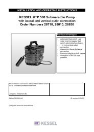
<strong>5.</strong> Installation and assembly<strong>5.</strong>2 Filling materialThe separator must only be installed in non-cohesive or low-cohesivesoils (Group G1 to G2 to ATV-DVWU - A127).Substrate: Ro<strong>und</strong>-particle gravel(max. particle size 8/16) to DIN 4226-1Tank bed:Tank jacketing:SandRo<strong>und</strong>-particle gravel(max. particle size 8/16) to DIN 4226-1Area outside tank jacketing:Material with suitable propertiesCovering layer: Humus or similar<strong>5.</strong>3 Construction pitThe fo<strong>und</strong>ation must be horizontal and level in order to be ableto set up the system over the full surface, and must also affordadequate load-bearing capability. The substrate consists ofcompacted ro<strong>und</strong>-particle gravel (max. particle size 8/16, minimumdepth 30 cm, Dpr=95%), covered by 3 - 10 cm of compactedsand. The spacing between the construction pit walland the tank must be at least 70 cm. The embankments mustbe constructed to DIN 4124. The depth of the construction pitshould be such that the limits of the earth covering are not exceeded.MIN ≤ TEÜ ≤ MAX (see dimension drawing in the Chapter onTechnical Data).● Root penetrationIn case of installation in the vicinity of trees or shrubbery, penetrationby roots must be reliably prevented.● Installation on a sloping siteIn case of installation of the separator on a sloping site, caremust be taken to ensure that the laterally-acting soil pressureof unsecured soil is absorbed by a suitably dimensioned supportingwall.● Frost-free depth for all-year-ro<strong>und</strong> useAlways take care to observe the locally established frost-freedepth when installing the separator. In order to ensure thesmooth operation even in winter, the inlet and outlet pipes mustalso be laid at a frost-free depth during installation.<strong>5.</strong>4 Tests before installationImmediately before installation of the tank in the constructionpit, the responsible specialist of the company carrying out theinstallation must test and certify the following:- the integrity of the tank wall;- the proper condition of the construction pit, in particular withregard to the dimensions and substrate bedding;- the particle size of the filling material.≥ 50cm≥ 50cmb nachyyyyyyyyyyDIN 4124≥ 70cm≥ 70cmSubbase: ro<strong>und</strong>-grain gravel (max.graining 8/16) according to DIN4226-1 compacted with Dpr=95% Tank bed: compacted sand Tank Tank encasing: ro<strong>und</strong>-grain gravel(max. graining 8/16) according toDIN 4226-1 compacted withDpr=95% Area outside tank encasing: materialof suitableconsistence<strong>5.</strong>5 InstallationThe float and coalescence insert, if fitted, remain in the tank duringinstallation.● InsertionThe tanks must be placed carefully in the construction pit withthe aid of suitable lifting equipment and positioned on the substratebedding (see also the Chapter “Transport”).● Filling of the tank and the backfilling construction pitIn order to avoid deformation of the tank, the filling of the tankwith water and the construction pit should take place in parallel.The tank jacketing should be applied to a width of at least 50cm. The backfilling aro<strong>und</strong> the tank should take place in 30 cmincremental layers. Each layer should be compacted with lightcompaction devices (min. Dpr=95%). Damage to the tank walland displacement of the tank during and after installation mustbe avoided. The self-actuating closure keeps the system closedduring the complete filling process.● Connection of the tankAny transport safety devices fitted must be removed. Note: thepipe connection fittings must be protected against damage inorder to ensure the permanent integrity of the system. To makeconnection easier, the pipe connection fittings should be adequatelygreased.The transition from downpipes to horizontal pipes must bemade using two 45° elbows separated by an intermediate pipeat least 250 mm long. A calming section must be installed infront of the separator system, which must be at least 10x aslong as the nominal width of the feed pipe.Top layer: topsoil, road surface,concrete or similar≤ 20cm≤ 30cm≤ 30cm≤ 30cm≤ 30cm≤ 30cm≤ 30cm≤ 30cm≤ 30cm≤ 30cm3-10cm≥ 30cm35
<strong>5.</strong> Installation and assemblyWhen the construction pit has been filled and compacted tothe lower edge of the feed and outlet connections, the feedand outlet pipes are laid frost-free and connected.Instructions for the warning system: Lay the connectioncable or empty pipe during the earthworks.● Insert the lip seal DN 600 in the groove in the domeand apply greaseTelescopic attachment● Connection of the sample removal shaft.Sample removal devices must be installed in the directionof flow immediately after the separator. The sample removaldevice of the separator system must be freely accessibleand positioned so that only waste water is removed whichhas passed through the separator.● Connection of the warning system empty pipe,if applicableThe connecting section between the separator and controlunit must be kept as short as possible.Unnecessary changes of direction, in particular those withangles above 45°, should be avoided.The empty pipe for the cable should have a continual slopedown to the separator.The formation of condensation within the empty pipe can beminimised by an airtight closure of the empty pipe on theside of the control unit. A cable pull-through wire can alsobe laid for subsequent cable laying.17365842Lip seal DN600The top sectionmust be between100 mm and 200mm minimum insertionmay be reduced.Minimum insertiondepth 100 mmTank dome● Insert the telescopic KESSEL upper section into theopening of the separator and adjust to the required position.With the aid of the clamping ring, the upper sectioncan now be fixed in the required position (alignedwith the upper gro<strong>und</strong> level). The fine adjustment to thefinal height is then made with the aid of the setscrews.Slopes can easily be compensated for by the fully heightadjustableand inclining upper section. The upper sectionmust be adequately supported from <strong>und</strong>erneath and vibratedin using a flat-bed vibrator and a steel plate laidon the upper section.For greater installation depths, the special KESSEL intermediatepiece (Art. no. 917402), height 400 mm, intendedfor this purpose should be used.(1) KESSEL light fluid separator(2) Layer thickness sensor(3) Reverse flow sensor(4) Control unit(5) Housing for wall installation(6) Watertight cable connection(7) Attachment set(8) Empty pipe closure● remaining fillingFor installation in areas of heavy vehicle traffic (coverclass D), a reinforced concrete slab must be provided asthe upper layer. A corresponding formwork and reinforcementplan is available from KESSEL.36
<strong>5.</strong> Installation and assembly30°30°45°Fit the knuckle coupling to the end of the hose and fix with ahose clamp.Hook the hose with the knuckle coupling upwards in the stubconnection, lead to the extraction device and adjust to the requiredlength.Connect the hose and extraction device and fix using a hoseclamp. When the cover is closed, it must not be in contact withthe knuckle coupling.Hole forimplementation-set180↕1342 6 7A 60 mm diametercore hole bit shouldbe used for drillingout the conduit pipeconnection hole.5Inner sideOuter sideIllustration of the cistern<strong>5.</strong>6 Oil and sludge extraction(for shaft LW 1000 on request only)For normal disposal, the hose from the suction vehicle is heldin the light fluid separator and the complete contents pumpedout.The volume of light fluid is however significantly less thanthe total volume of the separator. Assistance is provided in thiscase by the oil extraction device.For disposal of the light fluid, the suction hose is connected tothe oil extraction device. The suction vehicle can then removeonly the volume corresponding to the maximum light fluidquantity.This means a significant reduction of the disposal quantity,which together saves both time and disposal costs, and causesless wear to the separator components. In the same wayas the oil extraction device, the disposal quantity can also besignificantly reduced by the sludge extraction device.This is beneficial particularly for businesses with a high level ofsludge. The complete separator can of course also be emptiedby the sludge extraction device.If both devices are used for disposal, it must be ensured thatthe oil is disposed of first, followed by the sludge.The retaining device is attached at the inlet, using the pipeclamp as shown in the drawing.Fit the oil extraction to the retaining device, set to the requiredheight x (see Table) and fix in position.Fit the sludge extraction to the retaining device, feed to the bottomand then fix in position.Fit the stub connections to the attachment as shown in the drawingusing the stainless steel screws provided.The holes must be made using a 3.5 mm diameter drill. Use thestub connection as a drilling template.(1) Cables to the probes(2) Cable screw-fittings(3) Union nut(4) Through-sealSludge extractionRetaining deviceStub connectionSludge(5) Empty pipe closure(6) Through-pipe(7) Empty pipeOil extraction37
<strong>5.</strong> Installation and assemblyLight fluid separator Art. No.99403.10B 99403.10BEX 99503.10B 99503.10BEX99403.10D 99403.10DEX 99503.10D 99503.10DEX99610.15B 99610.15BEX 99710.15B 99710.15BEX99610.15D 99610.15DEX 99710.15D 99710.15DEX99606.30B 99606.30BEX 99706.30B 99706.30BEX99606.30D 99606.30DEX 99706.30D 99706.30DEX99610.30B 99610.30BEX 99710.30B 99710.30BEX99610.30D 99610.30DEX 99710.30D 99710.30DEX99606.80B 99606.80BEX 99706.80B 99706.80BEX99606.80D 99606.80DEX 99706.80D 99706.80DEX99610.80B 99610.80BEX 99710.80B 99710.80BEX99610.80D 99610.80DEX 99710.80D 99710.80DEX9961<strong>5.</strong>80B 9961<strong>5.</strong>80BEX 9971<strong>5.</strong>80B 9971<strong>5.</strong>80BEX 99620.80B9961<strong>5.</strong>80D 9961<strong>5.</strong>80DEX 9971<strong>5.</strong>80D 9971<strong>5.</strong>80DEX 99620.80D99703.04B99703.04D99703.10B99703.10DDistance X of the oil extractionfrom the tank bottom950 mm1450 mmOn request38
6. CommissioningThe chapter "Safety instructions" must be heeded.6.1 Setting up for operationBefore the separator is put into operation, please make surethat: the separator is clean and the interior is free from any objectswhich may have been placed inside during shippingor installation. the separator is completely filled with clean cold water.Completely filling the separator is complete when waterbegins to drain from the outlet.6.2 Initial InstructionsPlacing the separator into full operation is normally handledby a licensed tradesman although upon request can be handledby a KESSEL representative.The following personnel should be on hand when the initialinstructions for placing the separator into operation are given: Building facilities manager Building maintenance workers Contracted plumber / tradesman Contracted disposal companyWhat to do: Check to make sure the separator is completely watertight.Check to make sure that during transport andinstallation that no damage to the separator wascaused. Check to make sure all connections to theseparator (inlet, outlet, refill, rinse pipes etc.) are inperfect working order. Representative should discuss all necessary informationregarding the disposal. Representative should take the customer step by stepthrough all stages of a separator disposal. After the separator has been emptied (disposed) allnecessary paperwork and documentation should behanded over to the customer. The separator should be returned to service by fillingthe separator with fresh, cold water.6.4 Hand-over of installation and user’s manual.6.5 Completion of the commissioning report.After commissioning has been completed the separatorshould be placed into normal operation mode.6.3 Commissioning report (see attachment)39
7. DisposalDisposal intervals:The fuel / oil collected in the separator should be collected /disposed when the level has reached 80% of the maximumstorage capacity. Disposal of collected sludge in the base ofthe separator should be collected / disposed when the levelhas reached 50% of the maximum sludge storage capacity.Important: Timely disposal of the separator is mandatory toinsure proper function and operation of the separator.A licensed disposal company should be contracted to handledisposal of the separator. Disposal should take place whenlittle or no wastewater is entering the separator.Emptying intervals:The light fluid retained in the separator must be removed at thelatest when the quantity of separated light fluid reaches 80% ofthe maximum storage quantity, or the level is below the retainedvolume. For separators simultaneously or exclusively usedfor the drainage of systems or areas where light fluids are handled(e.g. fuelling areas), the retained volume required <strong>und</strong>erstate regulations must also be provided. The separated lightfluid must also be removed at levels below this retained volumeif the quantity of separated light fluids has not yet reached80 % of the maximum storage quantity.The disposal of the sludge contained in the sludge trap mustbe removed at the latest when the separated sludge quantityreaches half of the sludge trap volume.Note: Light fluids and sludge must be removed as specifiedabove in order to ensure the correct operation of the system.For this reason, a disposal contract should be concluded witha specialist disposal company. The disposal work should becarried out if possible when the system is not in operation.Expected disposal volumes in accordance with the filling levelcan be estimated by means of the following table.The figures contained in the table are approximate figures onlyfor the purposes of estimating quantities when contracting aspecialist disposal company.40
7. DisposalOil-/fuel Separator Sludge Oil-/FuelArt.-Nr.: 1) Measured Disposal 2) Measured DisposalFilling level layer thickness volume Filling level layer thickness volumein % in mm in litres in % in mm in litres99403.10B 99403.10BEX 99503.10B 99503.10BEX 50 650 1000 100 131 18799403.10D 99403.10DEX 99503.10D 99503.10DEX 40 530 800 80 105 15030 430 600 60 79 11220 330 400 40 52 7510 210 200 20 26 3799610.15B 99610.15BEX 99710.15B 99710.15BEX 50 650 1500 100 131 26299610.15D 99610.15DEX 99710.15D 99710.15DEX 40 550 1200 80 105 21030 450 900 60 79 15720 340 600 40 52 10510 220 300 20 26 5299606.30B 99606.30BEX 99706.30B 99706.30BEX 50 1100 3000 100 138 26599606.30D 99606.30DEX 99706.30D 99706.30DEX 40 930 2400 80 110 21299610.30B 99610.30BEX 99710.30B 99710.30BEX 30 760 1800 60 83 15999610.30D 99610.30DEX 99710.30D 99710.30DEX 20 580 1200 40 55 10610 370 600 20 28 5399606.80B 99606.80BEX 99706.80B 99706.80BEX 50 1100 4000 100 138 38099606.80D 99606.80DEX 99706.80D 99706.80DEX 40 910 3200 80 110 30499610.80B 99610.80BEX 99710.80B 99710.80BEX 30 740 2400 60 83 22899610.80D 99610.80DEX 99710.80D 99710.80DEX 20 560 1600 40 55 1529961<strong>5.</strong>80B 9961<strong>5.</strong>80BEX 9971<strong>5.</strong>80B 9971<strong>5.</strong>80BEX 10 350 800 20 28 769961<strong>5.</strong>80D 9961<strong>5.</strong>80DEX 9971<strong>5.</strong>80D 9971<strong>5.</strong>80DEX99620.80B99620.80D99703.04B 50 400 550 100 235 20099703.04D 40 320 369 80 188 16030 240 305 60 141 12020 160 241 40 94 8010 80 177 20 47 4099703.10B 50 800 1050 100 235 20099703.10D 40 640 815 80 188 16030 480 587 60 141 12020 320 369 40 94 8010 160 241 20 47 4099706.10B 50 400 550 100 235 20099706.10D 40 320 369 80 188 16030 240 305 60 141 12020 160 241 40 94 8010 80 177 20 47 401) The sludge retained in the separator must be disposed of at the latest at a filling level of 50%.2) The light fluid retained in the separator must be disposed of at the latest at a filling level of 80%, or when the retained volume is exceeded.maximale SchichtdickeLeichtflüssigkeitsmax. sludge thickness max. oil/fuel thicknessmaximale SchichtdickeSchlammWater Ruhewasserspiegel level80% Füllgrad full,separator - Leichtflüssigkeit should muss be entsorgt emptied werden100% full,100% Füllgradfloat - selbsttätiger switch Abschluss closes schließt41
8. Maintenance and ControlsINSTALLATION SELF-CHECK MAINTENANCE DISPOSAL GENERAL INSPECTION REPAIRWho Specialist company Specialist Specialist company or Disposal company Qualified body Specialist companyworks customer service 1What Measurement of the Measurement of the Removal of light fluid ˛ Complete emptyinglayer thickness of : layer thickness of : and sludge ˛ Cleaning· light fluid · light fluid ˛· of the sludge layer · of the sludge layerCheck of the self-actuating Check of the self-actuating The waste disposalclosure and warning device closure and warning device regulations mustbe observed!· Emptying and cleaning,if necessary· Cleaning of the sampleremoval device· Check of the operatinglogbookCheck for proper condition and proper operation, andat least however:- Safety against the escape of light fluids from the separatorsystem or the shaft units (excess height)- Structural condition and integrity of the separator system- Condition of the installed parts and the electricalequipment- Calibration of the self-actuating closure device- Completeness and plausibility of the records in theoperating logbook- Disposal confirmations of the materials removed- Availability and completeness of the requiredapprovals and documentationIf the separator system is also used for the treatmentof commercial waste water or waste water from thecleaning of vehicles, the following points must also bechecked:- Actual volume of waste water (origin, quantity, contents,cleaning agents, operating materials, avoidableof stable emulsions)- Dimensioning, suitability and performance of theseparator systems.When monthly 6-monthly Light fluid 80% is reached Before commissioning, then every 5 years -As requiredor the level is belowthe retained volumeSludge collection chamberis fullDocu- Installation certification operating logbook Maintenance report operating logbook Test report operating logbookmen- by specialist Maintenance reporttation* If the general inspection is carried out at shorter intervals than 5 years, the maintenance must be carried out by a specialist.42
8. Maintenance and ControlsThe Chapter “Safety instructions” must be observed!8.1 Maintenance● The separator system must be maintained semiannual by aspecialist 1).In addition to the removal of materials, the following work mustalso be carried out:- Check of the inner wall surfaces of the sludge trap and thegrease separator,- Functional check of the electrical devices and installations,if fitted.- The findings and work carried out must be recorded in theoperating logbook and evaluated.● If fitted, electro-mechanical assemblies such as pumps, valves,shut-off devices etc. must be maintained twice yearly inaccordance with the manufacturers’ instructions.8.2 Checking (general inspection)Before commissioning, and then at regular intervals of nomore than 5 years, the separator system must be completelyemptied and cleaned, and then checked by a specialist 2) forproper condition and operation.The following points at least must be checked and recorded:- Assessment of the separator system- Structural condition and integrity of the separator system- Condition of the inner wall surfaces of the installed parts andthe electrical equipment, if fitted- laying of the feed pipe of the separator system as a ventilationpipe over the roof- Completeness and plausibility of the records in the operatinglogbook- Confirmation of the proper disposal of the materials removedfrom the separator system- Availability and completeness of the required approvals anddocumentation (approvals, drainage plans, operating andmaintenance instructionsA checking report must be compiled on the checks performed,noting any existing faults. If faults are discovered, thesemust be rectified immediately.)1)A “specialist” in this sense refers to personnel of the operatoror other company, who by means of their training, skills andexperience obtained from practical work, ensure that theycarry out assessments or checks in the relevant specialisedfield to the required standard.A specialist can acquire the specialist knowledge required forthe operation and maintenance of separator systems in a trainingcourse with the following on-site instruction, which is offeredfor example by the corresponding manufacturers, professionaltrade associations, chambers of commerce and expertorganisations in the field of separator technology.2)A “specialist” in this sense refers to personnel of businessother than the operator, experts or other institutions which demonstrablyhave the specialist skills required for the operation,maintenance and checking of separator systems. In individualcases, such as larger operating units for example, thesechecks can also be carried out by internally independent specialistsof the operator not bo<strong>und</strong> by instructions with regardto their area of responsibility, who have equivalent qualificationsand technical equipment.Qualified bodies are specialist businesses independent of theoperator or similar institutions, whose employees demonstrablyhave the specialist skills required for the operation, maintenanceand checking of separator systems to the extent specifiedhere, together with the technical equipment for thechecking of separator systems.In individual cases, such as larger operating units for example,these checks can also be carried out by internally independentspecialists of the operator not bo<strong>und</strong> by instructionswith regard to their area of responsibility, who have equivalentqualifications and technical equipment.ArticleOrder No.General inspection of oil/coalescence separator 917 411/LOperating logbook of oil/coalescence separator 917 81243
9. Accessories / Replacement parts„SonicControl OSA“ automated measuring device with ultra sonic sensorfor oil / fuel separatorsCentimeter accurate monitoring and display of oil / fuel and sludge layer thicknessesalong with backwater / flooding alarm. Control unit with battery back upand remote alarm speaker connection. With connection set for easy on site controlunit mounting. For use with KESSEL <strong>und</strong>ergro<strong>und</strong> oil and coalescence separators.Control unit with optical and audible alarms and potential free contact(BMS) connection. Offers 12 month running log book and data downloadingcapability via USB connection.Operating voltage: 230 Volt / 50 Hz(twin prong German style plug)Art.Nr.Protection class: IP 54 Sensor917824cable length: 30 meters„SonicControl OS“ automated measuring device with ultra sonic sensorfor oil / fuel separatorsCentimeter accurate monitoring and display of oil and sludge layer thicknesses.Control unit with battery back up and remote alarm speaker connection. Withconnection set for easy on site control unit mounting. For use with KESSEL <strong>und</strong>ergro<strong>und</strong>oil and coalescence separators. Control unit with optical and audiblealarms and potential free contact (BMS) connection. Offers 12 month runninglog book and data downloading capability via USB connection.Operating voltage: 230 Volt / 50 Hz(twin prong German style plug)Art.Nr.Protection class: IP 54 Sensor917825cable length: 30 meters„SonicControl SA“ automated measuring device with ultra sonic sensor foroil / fuel separatorsCentimeter accurate monitoring and display of sludge layer thickness along withbackwater / flooding alarm. Control unit with battery back up and remote alarmspeaker connection. With connection set for easy on site control unit mounting.For use with KESSEL <strong>und</strong>ergro<strong>und</strong> oil and coalescence separators. Control unitwith optical and audible alarms and potential free contact (BMS) connection. Offers12 month running log book and data downloading capability via USBconnection.Operating voltage: 230 Volt / 50 Hz(twin prong German style plug)Art.Nr.Protection class: IP 54 Sensor917827cable length: 30 metersKESSEL Oil Suction SystemSuction pipe B 50 with Bi 50 suction hose for on-site connection to interior of uppersection, with Storz 52 C connection coupling.InletArt.No.DN 150 917 803DN 200 917 808KESSEL Sludge Extraction SystemSuction pipe B 50 with sludge suction funnel, 0.5m re-enforced suction hose Bi 50for on-site connection to interior of upper section, with Storz 52 C connection coupling..InletArt.No.DN 150 917 804DN 200 917 80944
9. Accessories / Replacement partsKESSEL-Coalescence filter insertArt.No.917 805KESSEL-Coalescence filter replacement partfor KESSEL-Coalescence separator LW 1000Art.No.917 81610. Warranty1. In the case that a KESSEL product is defective, KESSEL hasthe option of repairing or replacing the product. If the productremains defective after the second attempt to repair or replacethe product or it is economically unfeasible to repair or replacethe product, the customer has the right to cancel theorder / contract or reduce payment accordingly. KESSELmust be notified immediately in writing of defects in a product.In the case that the defect is not visible or difficult to detect,KESSEL must be notified immediately in writing of the defectas soon as it is discovered. If the product is repaired or replaced,the newly repaired or replaced product shall receivea new warranty identical to that which the original (defective)product was granted. The term defective product refers onlyto the product or part needing repair or replacement and notnecessarily to the entire product or unit. KESSEL products arewarranted for a period of 24 month. This warranty period beginson the day the product is shipped form KESSEL to its customer.The warranty only applies to newly manufacturedproducts. Additional information can be fo<strong>und</strong> in section 377of the HGB.In addition to the standard warranty, KESSEL offers an additional20 year warranty on the polymer bodies of class I / IIfuel separators, grease separators, inspection chambers, wastewatertreatment systems and rainwater storage tanks. Thisadditional warranty applies to the watertightness, usabilityand structural so<strong>und</strong>ness of the product.A requirement of this additional warranty is that the product isproperly installed and operated in accordance with the validinstallation and user's manual as well as the correspondingnorms / regulations.2. Wear and tear on a product will not be considered a defect.Problems with products resulting from improper installation,handling or maintenance will also be considered a defect.Note: Only the manufacturer may open sealed components orscrew connections. Otherwise, the warranty may become nulland void01.06.201045
SeparatorSeparatorCharacteristicscharacteristicsMat.-DescriptionMat.-No./Order-No./Prod. DateRef.No./Material/WeightEN/ApprovalDimensionsVolumeDensityDescription 1Description 2This unit has been checked for watertightness to be sure that it is fully operational before leaving the factory.Date Name of examiner46 16
Important contacts / InfoSeparator Type:__________________________________________________________Day / Hour__________________________________________________________Project description /Building services supervisor __________________________________________________________AddressTelephone / Fax____________________________________________________________________________________________________________________BuilderAddressTelephone / Fax______________________________________________________________________________________________________________________________________________________________________________PlannerAddressTelephone / Fax______________________________________________________________________________________________________________________________________________________________________________Contracted plumbing companyAddressTelephone / Fax______________________________________________________________________________________________________________________________________________________________________________KESSEL-Commissions no.:System operator /ownerAddressTelephone / Fax______________________________________________________________________________________________________________________________________________________________________________UserAddressTelephone / Fax______________________________________________________________________________________________________________________________________________________________________________Person of delivery__________________________________________________________Other remarks__________________________________________________________The system operator, and those responsible, were present during the commissioning of this system.____________________________ ____________________________ ____________________________Place and date Signature owner Signature user47
❑ Backwater protection❑ Lifting Stations and pumps❑ Drains and shower channels❑ Separators-Grease Separators-Oil-/Fuel-/CoalescenceSeparators-Starch Separators-SedimentSeparators❑ Septic Systems❑ Inspection Chambers❑ Rainwater ManagementSystems
GUIDE POUR L'INSTALLATION, LE SERVICE ET LA MAINTENANCEKESSEL - Séparateur d´hydrocarburesSelon la norme EN 858 en polyéthylène NS 3-20Séparateur d'huile et d'essence KESSELSéparateur à coalescence KESSELNS 3-20 pour installation dans le sol99 403 - 99 620(.10/.15/.30/.80) (B/D)99 503 - 99 720(.10/.15/.30/.80) (B/D)99 703 (.04/.10) (B/D)99706.10 (B/D)Avantages du produitPose dans la fouille facile etPas de machine lourde<strong>Montage</strong> simple, rapideMatériel écologiqueet recyclableTotalement étanche grâce laméthode de fabricationmonolithique sans soudureRéseau de serviceaprès-vente nationalNuméro d'admissionSéparateur d'huile etd'essence: Z-54.2-453Séparateur à coalescence:Z-54.3-454Installation Mise en service InstructionL'installation a été exécutée par votre entreprise spécialisée :Nom / signatureDateCachet de l'entreprise spécialiséeSous réserve de modifications techniques2013/01010-301FR
1. Consignes de sécuritéLe personnel qui effectue, le montage, le service, la maintenance et les réparations doit disposerde la qualification correspondante pour ces travaux. La responsabilité, la compétenceet la surveillance du personnel doivent être réglementées par l'exploitant. La fiabilité deservice de l'installation livrée n'est garantie qu'en cas d'utilisation conforme. Les limites desdonnées techniques doivent être respectés et ne peuvent être dépassées. Lors de la miseen place, du montage, du service, de la maintenance et des réparations de l'installation, ilfaut respecter les instructions de préventions des accidents, les normes correspondanteset les directives!Il s'agit notamment :• des instructions de préventions d'accident- Travaux de construction BGV C22- Documents sur les techniques d'eaux usées GUV-V C5• des règles de sécurité pour des travaux dans des locaux entourés de dispositifs techniquesd'eaux usées GUV-R 126• de la manipulation d'agents biologiques dans les dispositifs techniques d'eaux uséesGUVR 145• des directives pour les travaux dans des conteneurs et espaces étroits BGR 117• Normes• excavations, tranchées, talus, blindage et espace de travail DIN 4124• Pose et examen des canaux et canalisations des eaux usées DIN EN 1610• Aide de travail pour la sécurité et la protection sanitaire dans les dispositifs techniquesd'eauxusées.L'inobservation du mode d'emploi peut entrainer des dégâts matériels considérables, desblessures ou des accidents mortels.RISQUESSPÉCIFIQUES !AVERTISSEMENT !ATTENTION !• Dangers du aux gaz et vapeurs engendrant risque d'étouffement, d'intoxication et d'explosion• Danger de chute• Risque de noyade• Germes présents et eaux usées contenant des matières fécales• Charges physiques et psychiques élevées lors des travaux dans des espaces profonds,étroits ou sombres• Et autresL'inobservation du mode d'emploi peut entrainer des dégâts matériels considérables, desblessures ou des accidents mortelsL'installation ne forme qu'une partie d'une installation totale. C'est pourquoi vous devezégalement faire attention aux modes d'emploi de l'installation totale et des différents composants.Lors de chaque montage, maintenance, inspection et réparation de l'un des composants,il faut toujours mettre l'installation totale hors service et la garantir contre toute remiseinvolontaire en service.La reconstruction ou les changements de l'installation ne peuvent être exécutés qu'avecl'accord du fabricant. Les pièces de rechange d'origine et les accessoires autorisés par lefabricant garantissent la sécurité. L'utilisation d'autres pièces peut entraîner la cessationde la garantie.50
Table des matières1. Consignes de sécurité ................................................................................. Page 502. Domaine d'emploi 2.1 Domaine d'emploi .................................................... Page 522.2 Description de l'installation ...................................... Page 532.3 Description du fonctionnement................................. Page 533. Données techniques 3.1 Propositions d'installation séparateur d'hydrocarbure ............. Page 543.2 Dessin coté séparateur d'hydrocarbure ............................... Page 543.3 Proposition d'installationdu séparateur à coalescence de la citerne................................... Page 553.4 Dessin coté du séparateur à coalescence de la citerne........... Page 553.5 Projection du séparateur à coalescence puits LW 1000, NS 3 ..... Page 563.6 Dessin coté du séparateur à coalescence puits LW1000, NS 3..... Page 563.7 Dessin coté du séparateur à coalescence puits LW1000, NS 6.. Page 564. Emballage, transport 4.1 Emballage et stockage ............................................ Page 574.2 Transport .................................................................. Page 574.3 Stockage .................................................................. Page 57<strong>5.</strong> Mise en place et montage <strong>5.</strong>1 Conditions de mise en place .................................... Page 58<strong>5.</strong>2 2 Matériaux de remblai............................................. Page 59<strong>5.</strong>3 Fouille de construction ............................................ Page 59<strong>5.</strong>4 Contrôles avant la mise en place ............................ Page 59<strong>5.</strong>5 Mise en place ........................................................... Page 59<strong>5.</strong>6 Aspiration d'huile et de vase ................................... Page 616. Mise en service 6.1 Mettre l'installation en ordre de marche ................... Page 636.2 Instruction / Transfert .............................................. Page 636.3 Procès-verbal de remise ......................................... Page 637. Elimination des déchets .............................................................................................. Page 648. Propre contrôle, maintenance et contrôle ............................................................................... Page 669. Pièces de rechange et accessoires ............................................................................................. Page 6810. Garantie .............................................................................................. Page 6911. Certificat de l'installation / réception de la commande .......................................................... Page 70Procès-verbal de remise .............................................................................................. Page 7151
Cher client,Nous nous réjouissons que vous ayez choisi un produit KESSEL.Avant de quitter l'usine toute l'installation a été soumise a un sévère contrôle de qualité. Veuillez pourtant vérifier immédiatementsi l'installation vous a été livrée entière et sans dommages. En cas de dommage du au transport, veuillez appliquerles instructions du chapitre "Garanties" de ce guide.Ce guide d'installation, de service et de maintenance contient des instructions importantes qui doivent être respectéeslors de la mise en place, du montage, du service, de la maintenance et des réparations. Avant d'exécuter un quelconquetravail sur l'installation, l'exploitant ainsi que le personnel spécialise compétent doivent lire attentivement ce guide ets'y conformer.Important ! Les instructions, valeurs, données, etc. indiquées dans ce guide et concernant l'installation, le service et lamaintenance se rapportent a la statique examinée et ne peuvent pas être appliquées á d'autres produits.KESSEL AG2. Domaine d'emploi2. Généralités2.1 Domaine d'emploiLes séparateurs sont prévus pour fonctionner dans les conditionsfixées, cf. chapitre „Mise en place et montage“, exclusivemententerres en plein air ou en dessous d'une dalle defondation dans des locaux bien ventiles.2.1.1 Séparateur d'hydrocarbure classe IILes séparateurs peuvent être utiliser :a) pour le traitement de l'eau de pluie polluée par des liquidesvolatils provenant des aires de lavages, par exemple,des stations essence, des dépôts de pétrole et des terminauxpétroliers, des parkings et rues dans les zones deprotection et de captage des eauxb) comme dispositif de retenue pour des liquides volatils d'installationset de surfaces qui ont a faire avec des liquidesvolatils, par exemple des stations essence, des dépôts depétrole et des terminaux pétroliers c) Pour la pré-séparationdes liquides volatils des eaux usées qui sont soumisespar la suite a un traitement continu dans les installationsde traitement d'eaux usées internes a l'- exploitation.Dans les cas a) et b), l'eau pluviale des séparateurs estdestinée a être déversées dans les systèmes d'assainissementpublics. Pour autant que l'eau pluviale rejoigne desnappes d'eauxvive des conduites, ceci n'est possible, dans un cas isole,qu'après la purification d'une telle conduite et / ou de demandessupplémentaires nécessaires auprès du service publicd'eau compétent local Lors du traitement d'eau usée polluéepar des liquides volatils (eaux usées industrielles) oud'eaux usées des domaines d'application de l'annexe 49 dudécret sur les eaux usées, le respect d'une valeur limite pourdes hydrocarbures de 20mg/l peut ne pas être applique.2.1.2 Séparateur à coalescence selon classe I desséparateursLes séparateurs pour liquides volatils avec filtre acoalescence peuvent être utilisé :a) pour le traitement de l'eau de pluie polluée par des liquidesvolatils provenant des aires de lasvage, par exemple,des postes a essence, des dépôts de pétrole et des terminauxpétroliers, des parkings et rues dans les zones deprotection et de captage des eauxb) comme dispositif de retenue pour des liquides volatils pourla protection d'installations et de surfaces qui ont a faireavec des liquides volatils, par exemple des postes a essence,des dépôts de pétrole et des terminaux pétroliersc) pour le traitement d'eaux usées polluées par des liquidesvolatils (eaux usées industrielles) qui en prenant en considérationles conditions d'exploitation lors des processus industriels,contribue au nettoyage des parties pollués parl'huile et au nettoyage des sols pollués par l'huile (a l'exceptiondes sols d'atelier),d) pour le traitement des eaux usées, en tenant compte desconditions d'exploitation lors du nettoyage automatique devéhicules (courant partiel : décompression devant l'installationde recyclage avec ouverture bien adaptée), lors dunettoyage manuel (Karcher, lavage du moteur, lavage dudessous, nettoyage du châssis dans des grandes installationsde lavage ainsi que dans des postes de lavage industriels- sauf le nettoyage des sols d'atelier polluées parl'huile) et pour le drainage des surfaces de réception, destockage d'entrée, d'assèchement, de démontage et compressionde vieux véhiculese) Pour la pré-séparation des liquides volatils des eaux uséesqui sont soumises par la suite a un traitement continu dansles installations de traitement d'eaux usées internes a l'- exloitation.52
2. Domaine d'emploiDans les cas a) et b), l'eau pluviale des séparateurs estdestinée a être déversées dans les systèmes d'assainissementpublics.Pour autant que l'eau pluviale rejoigne des nappes phréatiquedes conduites, ceci n'est possible dans un cas isole qu'âpresla purification d'une telle conduite et / ou de demandes supplémentairesnécessaires auprès du service public d'eaulocal. Les séparateurs qui sont utilisés dans le cas d) se trouventdans des installations destinées a la restriction des hydrocarburesdans les eaux usées contenant de l'huile minéraleau sens de la pièce E, paragraphe 2 de l'annexe 49 dudécret sur les eaux usées. La valeur de 20 mg/l exigée, d'âpresle droit des eaux, dans les cas c) et d) pour des hydrocarburesest considérée comme respectée.2.2 Description de l'installationLa figure montre une citerne de séparateur d'hydrocarbure,enterrée de classe A/B. Lieu de sortie sans siphon Séparateur de liquides volatils Arrivée avec siphon Sortie avec fermeture automatique Tube principal Flotteur Rehausse Couvercle Puits de prélèvement Protection de refoulement2.3 Description du fonctionnementSous l'action de la pesanteur, les séparateurs provoquent uneséparation des eaux usées des liquides volatils et de la vase.Par liquides volatils, il faut comprendre des liquides d'origineminérale avec une densité ≤ 0,95 g/cm3 qui ne sont pas oupeu solubles dans l'eau et insaponifiables. N'en font pas partiesles émulsions stables, les graisses et les huiles d'originevégétale ou animale. Les liquides volatils flottent dans l'espacede dégraissage et s'accumulent a la surface. Lesboues qui sont plus lourdes que l'eau se déposent au fond etforment une couche de vase.Les séparateurs avec filtre a coalescence fonctionnentcomme les séparateurs d'hydrocarbure, selon le principe depesanteur. Pour l'augmenter l'efficacité de séparation, un filtrea coalescence est place en plus dans la cuve. Ce filtre enforme de cylindre a deux fonctions. D'une part, il influence lecourant dans le séparateur, d'autre part, il "filtre" au traversdu matériau coalescent toutes les eaux usées.Si ce tissu de filtre est envahi par des eaux usées contenantde l'huile, les gouttelettes d´huiles ne se séparent plus et enraison de la force de pesanteur se rassemblent sur lematériau coalescent pour former de grandes gouttes. Lorsquecelles-ci ont atteint une taille plus résistante, elles sedétachent du matériel de filtrage et remontent a la surface.Les séparateurs de liquides volatils sont équipes en séried'une fermeture automatique.Si le débit maximal du récupérateur d'huile est dépasse, lemécanisme ferme la sortie vers la canalisation. La sortie desliquides volatils dans la canalisation est empêchée. Ce dispositifde sécurité se compose d'un tube principal rempli d'eaudans lequel se trouve un flotteur.Le flotteur est taré de telle sorte qu'il flotte à la surface et baissedansle liquide volatil (jusqu'a une densité de 0,95 g/cm3).Si le débit maximal du récupérateur d'huile maximum est atteint,l'huilepasse par les ouvertures latérales dans le tube aflotteur. Le flotteur s'abaisse alors vers le bas et ferme la sortiedu séparateur.La fermeture automatique d'un séparateur déclenche un "signald'alarme". S'il se déclenche en cas d'avarie, le séparateurest a considère comme étant hors service, une interventionest impératif.53
3. Données techniques3.1 Proposition d'installation : citerne-séparateur d'hydrocarbure KESSELLa figurine montre le séparateur d'hydrocarbure KESSEL de classe II avec le couvercle de classeB et le puits de prélèvement3.2 Dessin cotéDN 150 (Ø 160 mm): T-TEÜ = 155 mmDN 200(Ø 200 mm): T-TEÜ = 180 mmT-TEÜ = Hauteur de recouvrementclasse D: 700 mm ≤ TEÜ ≤ 1.500 mmclasse A/B: 700 mm ≤ TEÜ ≤ 1.800 mmNSSéparateur deboue en litresVolumes RécupérateurPoids enSaillie en mmtotaux en litres d'huile litres kg2020 4000 600CouvercleclasseNumérod'articleL max(mm)3080308035353535429542953860386035353535429542954295429599620.80B 429599620.80D 429554
3. Données techniques3.3 Proposition d'installation : citerne du : Séparateur à coalescence KESSELLa figurine montre le séparateur d'hydrocarbure KESSEL de classe I avec le couvercle de classe Bet le puits de prélèvement3.4 Dessin coté de la citerneDN 150 150 (Ø 160mm): T-TEÜ = 155 mmDN 200 (Ø 200mm) : T-TEÜ = 180 mmT-TEÜ =Hauteur de recouvrementKlasse D: 700 mm ≤ TEÜ ≤ 1.500 mmKlasse A/B: 700 mm ≤ TEÜ ≤ 1.800 mmNSSéparateur deboue en litresVolumes Récupérateurtotaux en litres d'huile litresSaillie enmmVolume total débourbeur comparable aux mesures selon la norme DINRéduction excentrique sortie et entrée DN 150 (Ø 160mm) coté exploitant possible, donc puits de prélèvementPoids enkgCouvercleclasseNumérod'articleL max(mm)3080308035353535429542953860386035353535429542954295429555
3. Données techniques3.5 Figure : séparateur à coalescence KESSELpuits LW 1000, NS 33.6 Dessin coté : séparateur à coalescence KESSELpuits LW 1000, NS 3NSSéparateur deboue en litresØVolumes RécupérateurSaillie en mmtotaux en litres d'huile litres3 800 100 1100 Ø 545 995 1105 1055 790 200 110 175 B 99703.04B3 800 100 1100 Ø 545 995 1105 1055 790 200 110 205 D 99703.04D3 1600 100 1100 Ø 545 995 1605 1555 1390 200 110 190 B 99703.10B3 1600 100 1100 Ø 545 995 1605 1555 1390 200 110 220 D 99703.10DøPoids enkgCouvercleclasseNumérod'article3.7 Dessin coté : séparateur à coalescence KESSEL puits LW 1000, NS 6 (avec débourbeur en amont )NSSéparateur deboue en litresØøVolumes RécupérateurSaillie en mmtotaux en litres d'huile litresPoids enkgCouvercleclasseNumérod'article6 1000 150 1100 Ø 560 1010 1090 1020 1580 200 110 305 B 99706.10B6 1000 150 1100 Ø 560 1010 1090 1020 1580 200 110 338 D 99706.10D56
4. Emballage, transport et stockageRespecter le chapitre Consignes de sécurité!4.1 EmballageSi l'on respecte les points suivants, il n'est pas nécessaired'emballer les cuves pour les transport ou les stockage.Remarque: il faut éviter que des corps hétérogènes (impuretés,poussière, etc.) ne pénètrent dans le séparateur. Sinécessaire, il faut fermer toutes les ouvertures.4.2 Transportl Le transport ne doit être exécute que par des sociétés quidisposent des expériences professionnelles, des appareils,installations et moyens de transport appropriesainsi que de personnel suffisamment formé.l Les cuves doivent être transportes de telle sorte qu'ils nesoient pas charges de manière non autorisée et qu'unchangement de position soit exclu pendant le transport.En cas de haubanage, celui doit être exécuté de façon ane pas endommager les cuves (par exemple, en utilisantdes bandes de tissu, des cordes de chanvre). L'emploi defilins d'acier ou de chaines est interdit.La figure montre la citerneLa figure montre la citernel Les cuves ne doivent pas être transportes a l'air libre etsans protection sur les surfaces de chargement ouvertesdes véhicules de transport. Les couvercles de protectionfixes avec des vis de retenue ne doivent être retires quejuste avant la mise en place.ici soulèventici soulèvent4.3 StockageS'il est nécessaire de procéder a un stockage des cuvesavant la mise en place, celui-ci ne peut être que de courtedurée et sur une surface plane, libre de tout obstacle tranchant. En cas de stockage en plein air, les cuves doiventêtre protèges contre les dommages, les mauvaises conditionsatmosphériques et la pollution.l Il faut éviter de procéder par mouvements brusques lorsdu levage, du déplacement et de la dépose a terre descuves. Si l'on utilise un chariot élévateur, les cuves doiventêtre sécurisées pendant le déplacement effectue aveccelui-ci. Aucune roulette ou boucle ne doit venir au contactdu fond du conteneur.Les cuves doivent être sécurisées contre les changementsde position inadmissibles pendant le transport. Lescuves ne doivent pas être endommages par le système defixation utilisée.La figure montre la citerne57
<strong>5.</strong> Mise en place et montagePendant l'entreposage du séparateur ainsi que jusqu'àla fin des travaux d'installation, il faut respecter des mesuresde protection appropriées au chantier de constructionpour empêcher des accidents et des dommagesaffectant le séparateur de liquides volatils.Respecter le chapitre Consignes de sécurité !<strong>5.</strong>1 Conditions de mise en placeLa mise en place ne peut être exécutée que par des sociétésqui disposent des expériences professionnelles, des appareilset installations appropriés ainsi que de personnelsuffisamment formé.Une étude de la nature du sol en vue de l'aptitude techniqueconcernant la construction doit être entreprise (classificationdu sol pour des buts techniques de construction DIN 18196).Le niveau maximal d'eau souterraine présent doit être déterminé.Le niveau d'eau souterraine ne doit pas dépasserle niveau de la sortie. Un détournement (drainage) suffisantdes eaux d'infiltration est impératif en cas de sols imperméables.Il faut calculer les types de charge susceptibles dese produire de même que les charges maximales de circulationet la profondeur d'installation.Les séparateurs destinés à être enterrés doivent être installésen dehors des bâtiments mais aussi près que possibledes arrivées. S'il y a lieu, il faut prévoir l'isolation ou lechauffage des tuyauteries de raccordement des sortiesmenant au séparateur. En cas d'utilisation de pièces télescopiques,il faudra avoir la profondeur d'installation hors gelnécessaire et disposer d'une adaptation simple des conduitesd'arrivée et de sortie (canal). Les couvercles pour lesclasses de charge A / B et D ne sont pas vissés et respectentles conditions de l’EN 124.Les séparateurs à graisse doivent être installés près du lieud'arrivée des liquides volatils. Ils doivent être facilement accessiblespour le nettoyage et la maintenance.L'utilisation decouvercles verrouillés ou ventilés est interdite.Des stations de pompage ou des systèmes de levage nepeuvent pas être installées dans le dispositif d'arrivée avantle séparateur. Si de tels systèmes ou stations sont nécessaires,ils doivent être installés après le séparateur.Pour un fonctionnement sûr de l'installation, KESSEL recommandede prévoir, du côté de l'exploitant, un encorbellementainsi que le montage d'un dispositif d'alarme. Lesconditions de montage nécessaires doivent être réaliséesavant le remblayage de la fouille de construction.Les séparateurs à graisse doivent être installés de telle sorteque le bord supérieur des couvercles se trouve suffisammenthaut par rapport au niveau maximal de la surface à assainir(cf. image 1).Le niveau de liquide dans le séparateur se situe, en raisonde la différence de densité entre le liquide volatil et l'eau, esttoujours plus haut que la surface de l'eau dans le systèmede drainage.Le niveau déterminant est défini par la hauteur maximale deretenue des eaux de pluie lorsque des eaux usée et eaux depluie sont canalisées ensemble.Si seule de l'eau usée est introduite, c'est le bord supérieurde l'entrée connectée le plus bas qui est considéré commele niveau déterminant. Le dépassement nécessaire dépendde la grandeur nominale du séparateur (cf. chapitreDonnées techniques).Si cette surélévation ne peut pas être respectée, un dispositifd'alerte doit être installé pour les liquides volatils.Séparateur à graisse prêt à fonctionnerLes séparateurs de liquides volatils doivent être protégés,côté exploitation contre tout refoulement du canal.Surface d’assèchement Bord supérieur du couvercleEncorbellement /surélévationgFig. 1La figure montre la citerneKESSEL recommande les mesures préventives de protectionsuivantes :Lieu de sortie Séparateur Protectioncontre refoulement A l'intérieur Clapetd'un bâtiment anti-refoulementcontre refoulement pas de saillie Clapetanti-refoulementEn dehors Encorbellement Clapetd'un bâtiment disponible anti-refoulementEn dehors pas de saillie Système de levaged'un bâtimentVeuillez considérer:• Les influences qui peuvent être liées aux conditionsmétéorologiques• Le refroidissement des cuves pendant la phase d´installationou le remplissage avec de l'eau froide (Ex: Séparateursà graisses/hydrocarbures pour la pose enterrer et lesmicros stations dépuration) peuvent provoquer sur lescuves, des différences de mesures par rapport auxdonnées du catalogue.Veuillez vérifier avant l´installation, les dimensions, en particulierla hauteur réelle de la cuve par rapport aux indications.58
<strong>5.</strong> Mise en place et montage<strong>5.</strong>2 Matériau de remblaiLe séparateur ne peut être installé que dans un sol peu compactà très compact (groupe G1 jusqu'à G2 après ATV-DVWU - A127).Fondation:Gravier rond (granulation maximale8/16) selon DIN 4226-1Lit du conteneur : SableEnveloppe duGravier rond (granulationconteneur: maximale 8/16) selon DIN 4226-1Zone extérieure Entouragedu conteneur:Matériau de qualité appropriéeCouche de couverture : Humus ou autres<strong>5.</strong>3 Fouille de constructionLe sol à bâtir doit être horizontal et plat pour pouvoir mettreen place l'installation sur toute la surface. En outre, le sol àbâtir doit garantir une force portative suffisante. La fondationsera formée d'un gravier rond comprimé (granulation maximale8/16, épaisseur au moins 30 cm, Dpr=95%) avec pardessus 3 - 10 cm de sable comprimé. La distance entre lemur de fouille de construction et le conteneur doit faire aumoins 70 cm. Les pentes doivent correspondre à la DIN4124. La profondeur de la fouille de construction doit être tellesque les limites de la couverture en terre ne seront pasdépassées.MIN ≤ TEÜ ≤ MAX (cf. dessin coté dans le chapitre Donnéestechniques). La distance minimale entre les différents bâtiments(par exemple entre le séparateur et le séparateur deboue raccordé) doit faire au moins 70 cm.l Pousse de racinesLa plantation, à proximité, d'arbres, de buissons et de plantesvivaces doit être empêchée afin d'éviter la pousse de racines.l Installation dans un terrain en penteEn cas d’installation du séparateur dans un terrain en pente,il faut absolument faire attention à ce que la poussée latéraledes terre, en cas de sol non meuble, soit compensée parun mur d'appui statique adapté.l Profondeur hors gel en cas d'utilisation toute l'annéeLors de la mise en place du séparateur, il faut impérativementfaire attention à la profondeur hors gel localement fixée. Pourgarantir un fonctionnement sans problème, également enhiver, les conduites d'arrivée et de sortie doivent, de même,être placées dans une profondeur de sol hors gel. En règlegénérale, la profondeur hors gel, sauf indi-cation contraire desservices publics, se situe à environ 80 cm.<strong>5.</strong>4 Contrôles avant la mise en placeJuste avant l'insertion du conteneur dans la fouille de construction,la personne compétente de la société chargée del'installation doit examiner les points suivants et les certifier- Intégrité des parois du conteneur;- Etat réglementaire de la fouille de construction, en particulierpar rapport aux mesurages et à la dalle de fondation ;- Qualité de la granulation du matériau de remblayage.La figure montre la citerne≥ 50cm≥ 50cmb nachyyyyyyyyyyDIN 4124≥ 70cm≥ 70cm Fondation: Gravier rond (granulation maximale 8/16) selon DIN 4226-1 Lit du conteneur : Sable Enveloppe du conteneur: Gravier rond (granulation maximale 8/16) selonDIN 4226-1 Zone extérieure Entourage du conteneur: Matériau de qualité appropriée Couche de couverture : Humus ou autres≤ 20cm≤ 30cm≤ 30cm≤ 30cm≤ 30cm≤ 30cm≤ 30cm≤ 30cm≤ 30cm≤ 30cm3-10cm≥ 30cm<strong>5.</strong>5 Mise en placeLes flotteurs et le séparateur à coalescence, si présents, demeurentdans le conteneur pendant la durée de mise enplace.l InsertionEn s'aidant de dispositifs appropriés, les conteneurs doiventêtre mis en place sans à-coups, dans la fouille de constructionet reposer sur la dalle de fondation (voir aussi le chapitre"Transport").l Remplissage du conteneur et remblayage de la fouillede constructionPour éviter des déformations du conteneur, avant de remplircelui-ci, il faut remblayer en même temps la fouille de construction.L'enveloppe du conteneur doit être réalisée sur une largeurd'au moins 50 cm. Les différentes couches ne doivent pasdépasser 30 cm. Elles doivent être comprimées avec de petitscompacteurs (min. Dpr=95%). Pendant et après la miseen place, les parois du conteneur ne doivent pas être endommagéesni celui-ci décalé. La fermeture automatiquemaintient l'installation close pendant tout le processus deremplissage.l Raccordement du conteneurLes sécurités de transport éventuellement présentes doiventêtre retirées. Attention, les pièces du tube de raccord doiventêtre protégées des dommages afin de garantir une étanchéitédurable. Pour faciliter le raccordement, les parties du tube deraccordement et leurs parties opposées doivent être suffisammentgraissées.Le passage entre les tuyaux de sortie et les conduites horizontalesdoit être réalisé avec deux coudes de tuyauterie à45 ° et une pièce intermédiaire d'au moins 250 mm de long.Devant le séparateur à graisse, il faut prévoir une distance d'a-59
<strong>5.</strong> Mise en place et montagepaisement dont la longueur corresponde à au moins 10 fois lediamètre nominal du tube d'arrivée.Lorsque la fouille de construction est comblée jusqu'au bordinférieur des raccords de conduites d'entrée et de sortie puiscomprimée, il faut mettre en place hors gel les conduitesd'entrée et de sortie puis les brancher.Instruction pour le dispositif d'alarme : mettre en place lecâble de jonction ou le tube vide pendant les travaux de terrassement.l Insérer dans la rainure et graisser le joint de lèvre DN 600dans la rainure du dôme.Rehausse télescopiquel Connecter le puits d'échantillonnageLes appareillages d'échantillonnage sont à disposer dans lesens du courant directement derrière le séparateur. L'appareillaged'échantillonnage du séparateur à graisse doitêtre disposé librement, de façon accessible et de telle sorteque l'on ne retire que des eaux usées qui proviennent duséparateur.Joint de lèvreDN 600Profondeur minimaled'insertion 100 mm4La partie supérieuredoit être compriseentre 100 mm et200 mm au minimumd'insertionpeut être réduite.Dôme de conteneur(1) Séparateur de liquides volatilsKESSEL(2) Capteur d'épaisseur de couche(3) Capteur d'arrêt(4) Pupitre de commande(5) Boîtier pour le montage mural(6) Liaison par câble étanche(7) Kit de fixation(8) Fermeture de tube videl Si nécessaire, connecter le tuyau vide du dispositifd'alarme.L'espace de jonction entre le séparateur et le pupitre de commandedoit être le plus court possible.Les changements de direction inutiles, en particulier, ceuxavec des coudes supérieurs à 45 ° sont à éviter.Le tube vide pour câble doit présenter une pente permanentejusqu'au séparateur.La formation d'eau de condensation à l'intérieur du tube videpour câble peut être réduite en fermant hermétiquement letube vide du côté du pupitre de commande. Les pré-câblagessupplémentaires éventuels peuvent être réalisés avecun passe-câble.8l La rehausse télescopique KESSEL doit être raccourciede telle sorte que tous les éléments de montage puissentêtre entretenus sans problèmes. Avant l'insertion, réaliser unbiseautage à 15° pour éviter d'endommager le joint. Enficherensuite la rehausse dans l'ouverture du séparateur et l'amenerà la position souhaitée. Maintenant à l'aide de l'anneaude serrage disponible, il est possible de fixer la rehaussedans la position souhaitée (alignement au bordsupérieur du sol). Avec les vis de réglage, procéder à l'ajustagefinal à la hauteur définitive. Les inclinaisons du sol peuventêtre facilement égalisées avec la rehausse qui permetd'effectuer de manière continue, un réglage en hauteur et eninclinaison. La rehausse est suffisante pour effectuer le remplissage,puis terminer la mise en place moyen d'unedameuse plate et d'une plaque d'acier disposée sur la rehausse.Pour de plus grandes profondeurs d'installation, il faut utiliserla rehausse KESSEL (n° d'article 917402) spécialeprévue à cet effet, ce qui permet d'avoir une hauteur de construction400 mm.l Remblai restantEn cas de mise en place dans des zones où circulent des camions(couvercle classe D) il faut prévoir comme couchesupérieure une dalle en béton armé. Un plan de coffrage etd'armature adéquat est disponible chez KESSEL.60
<strong>5.</strong> Mise en place et montageBohrung fürDurchführungssset180↕30°30°45°Monter les éléments « Pinorrek » dans la rehausse, selon ledessin, avec les vis d'acier spéciales ci-jointesPour le forage, utiliser seulement un foret de Ø 3,5 mm. Utilisezle Pinorrek comme gabarit de forage.Monter l'accouplement Storz à l'extrémité du tube et fixeravec le collier de serrage.Accrocher le tuyau flexible avec l'accouplement Storz enhaut dans l'élément Pinorrek, le mener jusqu'à installationd'aspiration et le couper pour adapter la longueurRelier le tuyau flexible et l'installation d'aspiration et les fixeravec le collier de serrage.Lorsque le couvercle est fermé, celui-ci ne doit pas toucherl'accouplement StorzLa figure montrela citerne<strong>5.</strong>5 Aspiration d'huile et de vase(pour puits LW 1000 uniquement sur demande)En cas d'élimination normale des déchets, le tuyau flexible vadu véhicule de nettoyage dans le séparateur de liquides volatilset tout le contenu est pompé.Cependant la quantité du liquide volatil est nettement plus petiteque le volume total du séparateur. Dans ce cas, l'appareil d'aspirationd'huile apporte son aide.Pour éliminer le liquide volatil, le flexible d'aspiration est connectéà l'appareil d'aspiration d'huile. Il est ainsi possible, grâce auvéhicule de nettoyage, d'évacuer la quantité qui correspond àla quantité maximale de liquide volatil.Cela signifie une nette réduction de la quantité de déchets à éliminer.Ceci permet de gagner du temps lors de l'élimination desdéchets, réduit les frais d'élimination et ménage les pièces duséparateur. Il en est de même pour l'appareil d'aspiration d'huile,la quantité de déchets à éliminer peut ici aussi être nettementréduite au moyen d'un aspirateur de boue.Ce dispositif est particulièrement avantageux pour les entreprisesqui ont à faire avec une forte arrivée de boue. Naturellementtout le séparateur peut également être vidé par l’aspirateur deboue.Si les deux dispositifs entrent en action pendant l'élimination desdéchets, il faut s'assurer que c'est d'abord l'huile qui est éliminéepuis la boue.Le dispositif d'arrêt est fixé à l'arrivée avec le collier conformémentau dessin.Monter l'aspiration d'huile sur le dispositif d'arrêt, à la hauteur xvoulue (voir tableau) régler et fixer.Monter l'aspiration de vase sur le dispositif d'arrêt, la mener jusqu'ausol puis la fixer.135Côté intérieur(1) Câble aux sondes(2) Passe-câbles à vis(3) Ecrou à chapeau(4) Joint de passageAspiration de vaseDispositif d'arrêt42 6 7VaseLors de l´installation d´unpassage de câbles, prévoirun percement avec unescie cloche de Ø 60 mmsur la cuve.Côté extérieur(5) Fermeture de tube vide(6) Tube de passage(7) Tube videAspiration d'huile61
<strong>5.</strong> Mise en place et montageSéparateur de liquides volatArt. Nr.99403.10B 99403.10BEX 99503.10B 99503.10BEX99403.10D 99403.10DEX 99503.10D 99503.10DEX99610.15B 99610.15BEX 99710.15B 99710.15BEX99610.15D 99610.15DEX 99710.15D 99710.15DEX99606.30B 99606.30BEX 99706.30B 99706.30BEX99606.30D 99606.30DEX 99706.30D 99706.30DEX99610.30B 99610.30BEX 99710.30B 99710.30BEX99610.30D 99610.30DEX 99710.30D 99710.30DEX99606.80B 99606.80BEX 99706.80B 99706.80BEX99606.80D 99606.80DEX 99706.80D 99706.80DEX99610.80B 99610.80BEX 99710.80B 99710.80BEX99610.80D 99610.80DEX 99710.80D 99710.80DEX9961<strong>5.</strong>80B 9961<strong>5.</strong>80BEX 9971<strong>5.</strong>80B 9971<strong>5.</strong>80BEX 99620.80B9961<strong>5.</strong>80D 9961<strong>5.</strong>80DEX 9971<strong>5.</strong>80D 9971<strong>5.</strong>80DEX 99620.80D99703.04B99703.04D99703.10B99703.10D99706.10B99706.10DDistance X entre l'aspirationd'huile et le fond du conteneur950 mm1450 mmsur demandesur demande62
6. Mise en serviceRespecter le chapitre Consignes de sécurité !6.1 Mettre l'installation en ordre de marcheIl faut rincer les conduites d'arrivée et de sortie.Avant l'amenée des eaux usées contenant de l'huile minérale,il faut➤ vider, nettoyer complètement et de nouveau remplir l'installation.➤ soulever le flotteur dans le tube principal et vérifier sa positionde flottage et sa mobilité. Séparateur à coalescence : l'introduiredans la direction prévue.6.2 Instruction / TransfertLa mise en service doit être exécutée par une entreprise spécialiséequalifiée.1. Les personnes suivantes doivent être présentes lors dutransfert➤ Personne responsable désignée par le maître del'ouvrage➤ Entreprise spécialisée2. Instruction:➤ Contrôle de l'installation, portant sur l'étanchéité, lesdégâts dus au transport et au montage ainsi que le contrôledes raccordements de conduite➤ Information sur l'élimination des déchets (aspiration)➤ Présentation pratique des possibilités d’utilisation3. Documentation➤ Transfert de l'instruction de montage et du mode d'emploi➤ Elaboration du procès-verbal de remise.6.3 Procès-verbal de remiseLe procès-verbal de remise doit être rempli complètementet signé par le responsable de la réception et l'exploitant de l'installationNous recommandons en outre la participation➤ du personnel de service➤ de l'entreprise spécialisée dans l'élimination des déchets63
7. Elimination des déchetsIntervalles de vidage :Le liquide volatil retenu dans le séparateur doit être retire auplus tard, lorsque la quantité du liquide volatil séparé a atteint80%de la quantité de stockage maximal, ou le volumede retenue a été dépassé négativement. Lorsque des séparateursqui servent simultanément ou exclusivement a la protectiond'installations ou de surfaces, dans ou sur lesquellesdes liquides volatils circulent (par exemple des surfaces deravitaillement), il faut respecter le volume de retenue nécessairedéfini par les prescriptions réglementaires du Land.C'est pourquoi le liquide volatil séparé doit être retire en casde dépassement négatif de ce volume de retenue, même sila quantité de liquides volatils sépares n'a pas encore atteint80% des capacités de stockage.L'élimination des déchets de la vase contenue dans le séparateurde boue doit s'effectuer au plus tard, quand la quantitéde vase séparée a rempli la moitie du volume du séparateurde boue.Attention: Seule une élimination des déchets de l'installationfaite dans les délais garantit un fonctionnementcorrectPour cette raison, il faudrait passer un contrat d'entretienavec une entreprise compétente. Les travaux d'éliminationdes déchets doivent être exécutés pendant les temps d'arrêtpar l'entreprise. Ne pas oublier que les cuves de déchetssont source de mauvaises odeurs.Les volumes d'élimination des déchets auxquels on doit s'attendreen fonction du degré de remplissage peuvent êtreévalué au moyen du tableau suivant.Les indications de ce tableau s'entendent comme des indicationsestimées à partir des quantités que doit traiter uneentreprise d'élimination des déchets64
7. Elimination des déchetsSéparateur de liquides volatils Vase liquides volatilsArt.-Nr.: 1) Epaisseur Volumes 2) Epaisseur VolumesNiveau de de couche d'élimination Niveau de de couche d'éliminationremplissage en % mesurée en mm des déchets litres remplissage en % mesurée en mm des déchets litres99403.10B 99403.10BEX 99503.10B 99503.10BEX 50 650 1000 100 131 18799403.10D 99403.10DEX 99503.10D 99503.10DEX 40 530 800 80 105 15030 430 600 60 79 11220 330 400 40 52 7510 210 200 20 26 3799610.15B 99610.15BEX 99710.15B 99710.15BEX 50 650 1500 100 131 26299610.15D 99610.15DEX 99710.15D 99710.15DEX 40 550 1200 80 105 21030 450 900 60 79 15720 340 600 40 52 10510 220 300 20 26 5299606.30B 99606.30BEX 99706.30B 99706.30BEX 50 1100 3000 100 138 26599606.30D 99606.30DEX 99706.30D 99706.30DEX 40 930 2400 80 110 21299610.30B 99610.30BEX 99710.30B 99710.30BEX 30 760 1800 60 83 15999610.30D 99610.30DEX 99710.30D 99710.30DEX 20 580 1200 40 55 10610 370 600 20 28 5399606.80B 99606.80BEX 99706.80B 99706.80BEX 50 1100 4000 100 138 38099606.80D 99606.80DEX 99706.80D 99706.80DEX 40 910 3200 80 110 30499610.80B 99610.80BEX 99710.80B 99710.80BEX 30 740 2400 60 83 22899610.80D 99610.80DEX 99710.80D 99710.80DEX 20 560 1600 40 55 1529961<strong>5.</strong>80B 9961<strong>5.</strong>80BEX 9971<strong>5.</strong>80B 9971<strong>5.</strong>80BEX 10 350 800 20 28 769961<strong>5.</strong>80D 9961<strong>5.</strong>80DEX 9971<strong>5.</strong>80D 9971<strong>5.</strong>80DEX99620.80B99620.80D99703.04B 50 400 550 100 235 20099703.04D 40 320 369 80 188 16030 240 305 60 141 12020 160 241 40 94 8010 80 177 20 47 4099703.10B 50 800 1050 100 235 20099703.10D 40 640 815 80 188 16030 480 587 60 141 12020 320 369 40 94 8010 160 241 20 47 4099706.10B 50 400 550 100 235 20099706.10D 40 320 369 80 188 16030 240 305 60 141 12020 160 241 40 94 8010 80 177 20 47 401) La vase retenue dans le séparateur doit être éliminée au plus tard lorsque le niveau de remplissage atteint 50%.2) Le liquide volatil retenu dans le séparateur doit être éliminé au plus tard lorsque le niveau de remplissage atteint 80% ou que le volume de retenue a été dépassé négativement.maximale Epaisseur SchichtdickemaximalLeichtflüssigkeitsd´hydrocarbureNiveau Ruhewasserspiegel d´eau en phase reposRemplissage 80% Füllgrad à 80% enhydrocarbure - Leichtflüssigkeit effectuer muss entsorgt une werden vidangemaximale SchichtdickeSchlammEpaisseur maximalde boueRemplissage à 100% fermeture100% Füllgrad- automatique selbsttätiger Abschluss de la sortie schließt65
8. Propre contrôle, maintenance et contrôleMISE ENPLACEPROPRECONTROLEMAINTENANCE ELIMINATION DES DE-CHETSINSPECTION GENERALE REPARATIONSQui EntreprisespécialiséePersonnecompétentePersonnecompétenteEliminateur de déchets Personne compétente EntreprisespécialiséeQuoi Mesure del'épaisseur decouche :· des élémentsvolatils· de la couche devaseContrôle de la fermetureautomatiqueet du dispositifd'alerte(après exécutiond'une inspectiongénérale, la premièrefois au boutde 6 mois)Mesure de l'épaisseurde couche :· des éléments volatils· de la couche devase. contrôle de la fermetureautomatiqueet des dispositifsd'alerte· Vidage et nettoyage,si nécessaire· Nettoyage de l'appareillaged'échantillonnage· Contrôle du journald’entrepriseElimination des éléments volatils etde la boueRespecter les prescriptions légalesrelatives à l'élimination desdéchets !Remplir à nouveau le séparateur àgraisse avec de l'eau qui correspondeaux conditions d'apport locales.˛ Vidage complet˛ Nettoyage˛ Contrôle conforme aux règles et exploitation correspondante,avec au moins cependant :· données portant sur le lieu du contrôle, l'exploitant de l'installationavec indication des données d'inventaire, la commandedu donneur d'ordre, le contrôleur et l'autorité publique compétente· Sécurité contre l'échappement d'éléments volatils du séparateurà graisse ou de fosses(surélévation / dispositif d'alarme)· Etat constructif du séparateur à graisse· Etanchéité du séparateur à graisse y compris dispositif desortie et poste d'échantillonnage intégré (contrôled'étanchéité selon DIN 1999-100, section 15)· Etat des surfaces de cloison et/ ou du revêtement intérieurdes éléments de montage et des installations électriques (side telles sont présentes)· Tarage de la fermeture automatique par détermination dupoids et du volume du flotteur· Intégrité et plausibilité des enregistrements dans le journald'entreprise· Preuve de l'élimination réglementaire des déchets contenusdans le séparateur à graisse· Présences et intégrité des accords nécessaires et des documents(autorisations, plans de drainage, modes d'emploi etdirectives de maintenance, etc.)· Apport réel d'eaux usées (origine, production possible maximaled'eaux de pluies et d'eaux usées, matières de conteneur.Evaluation, aptitude et capacité du séparateur à graissepar rapport à l'apport réel d'eaux usées).Quand Mensuel Semestriel Un volume de 80% en produits volatilsest atteint ou le volume deconfinement est dépassé négativementBoueLa chambre de collecte est remplieAvant la mise en service, puis tous les 5 ans En fonction desbesoinsDocumentationCertificat d'installationpar expertsJournal d’entrepriseRapport de maintenanceJournal d'entreprise Certificatd'élimination des déchetsRapport de contrôle Journal d'entreprise66
8. Propre contrôle, maintenance et contrôleRespecter le chapitre Consignes de sécurité !8. 1 Maintenance● Les opérations de maintenance sur le séparateur doiventêtre exécutées par une personne compétente 1) tous le sixmois.Outre les taches de l'élimination des déchets, il faut exécuterles travaux suivants :- Contrôle des surfaces de cloison du débourbeur et duséparateur ,- Contrôle de fonctionnement des systèmes électriques etdes installations, si disponibles.- Les contrôles et les travaux exécutes doivent être évaluéset reportes dans le journal d'entreprise.● Pour autant que présents, les blocs fonctionnels électromécaniques,tels que pompes, soupapes, organes d'obturation,etc. doivent être contrôles deux fois par an selon lesindications du fabricant.8.2 Contrôle (inspection générale)Avant la mise en service puis a l'issue, a intervalles réguliersmais au maximum tous les 5 ans, le séparateur, après vidagecomplet préalable et nettoyage, doit être contrôlé par unspécialiste 2) qui vérifiera son état réglementaire et son bonfonctionnement.De plus, il faut au moins contrôler et / ou inventorier les pointssuivants:- Dimensionnement du séparateur a graisse- Etat constructif et étanchéité du séparateur- Etat des cloisons internes des éléments de montage et desinstallations électriques, si présentes- Vérification de la conduite d'entrée du séparateur y comprisla conduite de ventilation- Intégrité et plausibilité des enregistrements dans le journald'entreprise- Preuve de l'élimination réglementaire des déchets retiresdu séparateur.- Présences et intégrité des agréments nécessaires et desdocuments (autorisations, plans de drainage, modes d'emploiet directives de maintenance)Une fois le contrôle exécuté, il faut rédiger un rapport de contrôlequi indiquera les manques éventuels. Si des défauts ontété constates, ceux-ci doivent être éliminés immédiatement.1) Est considéré comme "compétent" tout employé de l'exploitantou d'un tiers qui en raison de sa formation, de sesconnaissances et de son expérience obtenue par l'activitépratique, est en mesure d'exécuter convenablement desévaluations ou des contrôles dans le domaine respectif.La personne compétente peut acquérir la compétence pourl'exploitation et la maintenance des séparateurs, en suivantun stage de formation que dispensent par exemple les fabricantscorrespondants, les unions professionnelles, leschambres des métiers mais aussi en participant aux stagesdans la technique des séparateurs proposes par les organismesd'experts.2) Les personnes spécialistes sont des collaborateurs d'entreprisesindépendantes, des experts ou d'autres institutionsqui disposent manifestement des connaissances spécialesnécessaires pour l'exploitation, la maintenance et le contrôledes séparateurs. Dans certains cas particuliers, pour degrandes unités d'exploitation, ces contrôles peuvent êtreégalement exécutés par des experts indépendants et nonlies a l'entreprise et disposant de la même qualification et dumême équipement technique.Les postes qualifies sont des entreprises spécialisées indépendantesou d'autres institutions dont les collaborateurs ontmanifestement les connaissances spéciales nécessairespour l'exploitation, la maintenance et le contrôle des séparateursdans le volume cite ici mais aussi disposant de l'équipementtechnique d'appareil pour contrôle les séparateurs.Dans des cas isolés, au sein de plus grandes entreprises,ces contrôles peuvent être exécutes par des spécialistesinternes a l'entreprise, dans le cadre de leur domained'emploi et possédant la même qualification et le mêmeéquipement techniqueArticleRéférenceInspection général pour le séparateur avec filtre à coalescence 917 411/LRapport journalier pour le séparateur avec filtre à coalescence 917 812Etanchéité des conduites 917 41767
9. Pièces de rechange et accessoiresCompteur automatique « SonicControl OSA » avec le capteur ultrasoniquepour séparateur de liquides légerspour centimètre-précision, contrôle et reporting d'huile et de boue et d'avertissementdes barrages ; avec alimentation, Batterie et connexion de signaux éloignés.Avec Kit de fixation pour assemblage facile, côté bâtiment et d'entretien ; convientpour séparateur liquide léger pour une installation au sol de KESSEL. Unité decommande avec alarme optique et acoustique avec contact libre de potentiel ;journal électronique d'exploitation, conçu pour les 12 derniers mois ; Possibilité desélection de la revue d'exploitation via une interface USB.Tension de fonctionnement :230 V ~ 50 Hz ;Classe de protection : IP 54 ;Connecteurs :Schuko 2 pôles ;Art.Nr.Longueur du câble : 30 m917824Compteur automatique « OS SonicControl » avec capteur ultrasonique pourséparateur de liquide légercentimètre-précis de surveillance et de rapports d'huile et de boue ; avec alimentation,Batterie et connexion de signaux éloignés. Avec Kit de fixation pour assemblagefacile, côté bâtiment et d'entretien ; convient pour séparateur liquideléger pour une installation au sol de KESSEL. Unité de commande avec alarmeoptique et acoustique avec contact libre de potentiel ; journal électronique d'exploitation,conçu pour les 12 derniers mois ; Possibilité de sélection de la revue d'-exploitation via une interface USB.Tension de fonctionnement : 230 V ~ 50 Hz ;Classe de protection : IP 54 ;Art.Nr.Connecteurs : Schuko 2 pôles ;Longueur du câble : 30 m917825Acompteur libre « SonicControl SA » avec capteur ultrasonique pour séparateurde liquide lumièrecentimètre-précis de surveillance et de rapports d'huile et de boue ; avec alimentation,Batterie et connexion de signaux éloignés. Avec Kit de fixation pour assemblagefacile, côté bâtiment et d'entretien ; convient pour séparateur liquideléger pour une installation au sol de KESSEL. Unité de commande avec alarmeoptique et acoustique avec contact libre de potentiel ; journal électronique d'exploitation,conçu pour les 12 derniers mois ; Possibilité de sélection de la revue d'-exploitation via une interface USB.Tension de fonctionnement : 230 V ~ 50 Hz ;Classe de protection : IP 54 ;Art.Nr.Connecteurs : Schuko 2 pôles ;Longueur du câble : 30 m917827Appareil d'aspiration d'huile KESSELAppareil d'aspiration d'huile KESSELCoude d'aspiration B 50 mm, 0,5 m de flexible d'aspiration Bi 50 mm pour l'adaptationindividuelle a la rehausse en NBR avec la spirale de fil d'acier et les cordons Cu avecraccord pompier 52 C connecte et plaque dʼidentification.Alimentation Référence Equipement pour l´aspiration des hydrocarburesDN 150 (Ø160mm) 917 803DN 200 (Ø200mm) 917 808Aspirateur de boue KESSELTubulure d'admission B 50 mm avec hotte d'aspiration de boue 0,5 m de flexible d'aspirationBi 50 mm pour l'adaptation individuelle a la rehausse en NBR avec la spirale de fil d'acieret les cordons Cu avec raccord pompier 52 C connecte et plaque dʼidentification.Alimentation Référence Equipement pour l´aspiration des bouesDN 150 (Ø160mm) 917 804DN 200 (Ø200mm) 917 80968
9. Ersatzteile <strong>und</strong> ZubehörSéparateur avec filtre à coalescence KESSELPour la transformation de tous les séparateurs d'huile et d'essence KESSEL en séparateursà coalescenceArt.Nr.917 805Pièce de rechange KESSELfiltre à coalescence pour séparateur à coalescence KESSEL puits LW 1000Art.Nr.917 81610. Garantie1. Si une livraison ou une prestation est défectueuse, KESSELs’engage, selon votre choix, à éliminer, par réparation, le manqueconstaté ou à livrer un article sans défaut. Si la réparationéchoue par deux fois ou si elle n’est pas rentable financièrement,l'acheteur / le client a le droit de résilier le contrat ou de diminueren conséquence le paiement dû. La constatation de manquesévidents doit faire l’objet d’un compte-rendu immédiat ; en casde manques non reconnaissables ou cachés, ce compte-renduécrit sera envoyé dès que ces manques auront été constatés.KESSEL est responsable des réparations et livraisons postérieuresdans les mêmes conditions que celles de l'objet ducontrat originel. En cas de nouvelles livraisons, le délai de garantiereprend, mais seulement en ce qui concerne le volumed'une nouvelle livraison.Une garantie ne peut être transmise qu’aux objets nouvellementfabriqués.La durée de garantie est de 24 mois après livraison par notrecontractant.Le § 377 du HGB (code du commerce) sont applicables ultérieurement.En se basant sur la réglementation légale, KESSEL AG augmenteet accorde un délai de garantie de 20 ans s’appliquant auconteneur pour le décanteur, le dégraisseur, les puits, les petitesstations d'épuration et les citernes d'eau de pluie. Ceci concernel'étanchéité, l’aptitude à l'emploi et la sécurité statique.Il faut, pour cela que le montage ait été effectué par une entrepriseprofessionnelle et que l’exploitation se déroule conformémentaux directives de montage et de service ainsi qu’aux normesactuellement en vigueur.2. KESSEL rappelle que l'usure n'est pas un défaut pris en comptepar la garantie. Il en est de même pour les défauts dus à unemaintenance défectueuse.Note: L'ouverture des composants scellés ou des léments vissésne peut être exécutée que par le fabricant. Dans le cas contraire,les droits à garantie peuvent être exclus. "En date du 01.06.201069
Label de l´installation/contrôle technique en usine11. Certificat de l'installation / Réception de la commandeDesignation ArticleNo. deArt./de com./date de fabr.No.de rev./materiau/poidsNorme/AutorisationMesuresVolumeDensitéDésignation 1Désignation 2L´ingégralité et l´étanchéité de l´installation ont été contrôlées avant de quitter l´usine.Date Nom de contrôleur7016
Procès-verbal de remiseMarque et NS :__________________________________________________________Jour / heure__________________________________________________________Description de l’objetAdresseTéléphone / télécopie______________________________________________________________________________________________________________________________________________________________________________Maître de l'ouvrageAdresseTéléphone / télécopie______________________________________________________________________________________________________________________________________________________________________________PlanificateurAdresseTéléphone / télécopie______________________________________________________________________________________________________________________________________________________________________________Société sanitaire exécutriceAdresseTéléphone / télécopie______________________________________________________________________________________________________________________________________________________________________________N° de commission KESSELPersonne autorisée à réceptionnerAdresseTéléphone / télécopie______________________________________________________________________________________________________________________________________________________________________________Exploitant des installationsAdresseTéléphone / télécopie______________________________________________________________________________________________________________________________________________________________________________Responsable du transfert__________________________________________________________Autres assistants / divers__________________________________________________________La mise en service mentionnée et l’instruction ont été exécutées en présence de la personne autorisée à réceptionner etde l'exploitant des installations. Veuillez faire envoyer une copie à l'usine!____________________________ ____________________________ ____________________________Lieu, date Signature de la personne Signature l'exploitantautorisée à réceptionnerdes installations71
❑ Protections anti-reflux❑ Postes de relevageet pompes❑ Siphons❑ Séparateurs-Séparateurs à graisses-Séparateurs àhydrocarbures-Séparateurs à fécule-Décanteurs, débourbeurset dessableurs❑ Micro-stations d´épuration❑ Regards❑ Stations d´exploitationdes eaux pluviales
ISTRUZIONI PER L’INSTALLAZIONE, L’USO E LA MANUTENZIONESeparatori di liquidi leggeri KESSELconf. Norma europea EN 858 in polietilene NS 3-20Separatori di oli/benzina KESSELSeparatori di coalescenza KESSELN 3-20 per l’installazione interrata99 403 - 99 620(.10/.15/.30/.80) (B/D)99 503 - 99 720(.10/.15/.30/.80) (B/D)99 703 (.04/.10) (B/D)99706.10 (B/D)Vantaggi del prodottoFacile introduzione nelloscavo senza l’uso di gruMontaggio semplicee veloceMateriale riciclabileAssolutamente impermeabileall’acqua grazie al sistemacostruttivo monoliticoRete di assistenza su tutto ilterritorio federaleNumero di omologazioneZ-54.2-453Separatore di oli/benzinaZ-54.3-454Separatore di coalescenzaInstallazione Messa in funzione Le istruzionidell’impianto sono state fornite dal vostro rivenditore specializzato:Nome/Firma Data LuogoTimbro del rivenditore specializzatoCon riserva di modifiche tecnicheEdizione 2012/05No. di registrazione 010-301it
1. Avvertenze sulla sicurezzaIl personale addetto al montaggio, uso, manutenzione e riparazione deve disporre dellaqualifica necessaria per questi lavori. L’utente deve stabilire esattamente l’ambito di responsabilità,le competenze e la sorveglianza del personale.La sicurezza di funzionamento dell’impianto fornito è garantita solo in caso di uso conformealla destinazione. I valori limite dei dati tecnici non devono mai essere superati.Per l’installazione, l’uso, la manutenzione e riparazione dell’impianto, rispettare le normeantinfortunistiche, le norme e direttive pertinenti!Queste sono, tra l’altro:• “Norme antinfortunistiche – lavori di costruzione” BGV C22• Impianti di scarico GUV-V C5• Regole di sicurezza per lavori in spazi chiusi di impianti di scarico GUV-R 126• Uso di materiali biologici in impianti di scarico GUV-R 145• Direttive per lavori in cisterne e spazi ristretti BGR 117• Norme- scavi e fossati – pendii, installazione, larghezza dell’ambiente di lavoro DIN 4124- posa e controllo di condotte e canali di scarico DIN EN 1610• Ausili per la sicurezza e la tutela della salute in impianti di scarico.Pericoli sPecifici!• Pericoli derivanti da gas e vapori come pericolo di soffocamento, intossicazione ed esplosione• Pericolo di cadute• Pericolo di annegamento• Inquinamento batterico e acque di scarico contenenti sostanze fecali• Grande stress fisico e psichico durante il lavoro in ambienti profondi, ristretti o bui• e altroATTENZIONE!L’inosservanza delle istruzioni per il montaggio e l’uso può causare notevoli danni materiali,gravi lesioni personali o addirittura incidenti mortali.ATTENZIONE! !L’impianto è un componente di un impianto globale, quindi rispettare anche le istruzioni perl’uso dell’impianto globale e dei singoli componenti. Durante il montaggio, la manutenzione,ispezione e riparazione di uno dei componenti, mettere sempre fuori servizio l’intero impiantoe assicurarlo contro reinserimenti.Trasformazioni e modifiche dell’impianto devono essere eseguite solo previo accordo conil produttore. I pezzi di ricambio originali e gli accessori approvati dal produttore servonoalla sicurezza. L’uso di altri pezzi può esonerare il produttore dalla responsabilità per le conseguenzeda ciò risultanti.74
Indice1. Avvertenze sulla sicurezza Pagina 742. Campo d’impiego 2.1 Campo d’impiego Pagina 762.2 Descrizione dell’impianto Pagina 772.3 Descrizione del funzionamento Pagina 773. Dati tecnici 3.1 Suggerimento per l’installazione separatore di oli/benzina Pagina 783.2 Disegno quotato separatore di oli/benzina Pagina 783.3 Suggerimento per l’installazione separatore di coalescenza cisterna............ Pagina 783.4 Disegno quotato separatore di coalescenza cisterna Pagina 793.5 Illustrazione separatore di coalescenza pozzetto LW 1000, NS 3 Pagina 803.6 Disegno quotato separatore di coalescenza pozzetto LW 1000, NS 3 Pagina 803.7 Disegno quotato separatore di coalescenza pozzetto LW 1000, NS 6 Pagina 804. Imballaggio, trasporto 4.1 Imballaggio e stoccaggio Pagina 814.2 Trasporto Pagina 814.3 Stoccaggio Pagina 81<strong>5.</strong> Installazione e montaggio <strong>5.</strong>1 Presupposti per l’installazione Pagina 82<strong>5.</strong>2 Materiale di riempimento Pagina 83<strong>5.</strong>3 Scavo Pagina 83<strong>5.</strong>4 Controlli prima dell’installazione Pagina 83<strong>5.</strong>5 Installazione Pagina 83<strong>5.</strong>6 Aspirazione di olio e fango Pagina 856. Messa in funzione 6.1 Preparazione dell’impianto per la disponibilitàal funzionamento Pagina 876.2 Istruzioni / Consegna Pagina 876.3 Verbale di consegna Pagina 877. Smaltimento Pagina 888. Autocontrollo, manutenzione e verifica Pagina 909. Pezzi di ricambio e accessori Pagina 9210. Garanzia Pagina 9311. Scheda dell’impianto/ Collaudo della fabbrica Pagina 94Verbale di consegna Pagina 9575
Gentile cliente,siamo lieti che abbia optato per un prodotto della KESSEL.Prima di lasciare la fabbrica, l’intero impianto è stato sottoposto a un severo controllo della qualità. Verifichi tuttavia immediatamentese l’impianto Le è stato consegnato completo e non danneggiato. In caso di danni causati dal trasporto,osservare le indicazioni riportate nel capitolo “Garanzia” di queste istruzioni.Queste istruzioni per il montaggio e l’uso contengono informazioni importanti che devono essere rispettate durante il montaggio,l’uso, la manutenzione e riparazione. In caso di interventi sull’impianto, l’utente e il personale specializzato addettodevono leggere e seguire scrupolosamente queste istruzioni per il montaggio e l’uso.Importante! Le indicazioni, i valori, le disposizioni, ecc., riportati in queste istruzioni per l’installazione, l’uso e la manutenzionenon sono trasferibili ad altri prodotti a causa della statica verificata.KESSEL AG2. Campo d’impiego2. In generale2.1 Campo d’impiegoI separatori sono destinati, a condizioni stabilite, vedi capitolo“Installazione e montaggio”, esclusivamente per il montaggiointerrato all’aperto o sotto la piastra di fondazione inambienti ben ventilati.2.1.1 Separatori di oli/benzina conf. classe di separatoriIII separatori possono essere usati:a) per il trattamento di acqua piovana inquinata da liquidi leggeridi aree consolidate, p.es. stazioni di servizio, depositie punti di trasbordo di oli, parcheggi e strade in zone diprotezione delle acqueb) come dispositivo di ritenuta per liquidi leggeri di impianti esuperfici nei quali vengono manipolati liquidi leggeri, p.es.stazioni di servizio, depositi e punti di trasbordo di olic) per la separazione preliminare di liquidi leggeri da acquereflue che vengono sottoposte a un ulteriore trattamentoaziendale a valle in impianti per il trattamento delle acquedi scarico.Nei casi a) e b), l’acqua di scarico dei separatori è destinataal convogliamento negli impianti di drenaggio pubblici.Se l’acqua di scarico deve essere immessa in acque (fiume,lago ecc.), nel singolo caso questo è possibile solo dopo ilchiarimento con le autorità locali preposte dell’ammissibilitàdi una tale immissione e dei requisiti eventualmente necessari.In caso di trattamento di acque luride (acque di scarico industriali)inquinate da liquidi leggeri o di acque reflue provenientidai campi di applicazione dell’appendice 49 dell’ordinanzasulle acque di scarico, il rispetto di un valore limite peridrocarburi di 20 mg/l non può essere considerato come osservato.2.1.2 Separatore di coalescenza classe di separatori II separatori per liquidi leggeri con dispositivo di coalescenzapossono essere utilizzati:a) per il trattamento di acqua piovana inquinata da liquidi leggeridi aree consolidate, p.es. stazioni di servizio, depositie punti di trasbordo di oli, parcheggi e strade in zone diprotezione delle acque,b) come dispositivo di ritenuta per liquidi leggeri per la protezionedi impianti e superfici nei quali vengono manipolatiliquidi leggeri, p.es. stazioni di servizio, depositi e punti ditrasbordo di oli,c) per il trattamento di acque luride (acque di scarico industriali)inquinate da liquidi leggeri che, secondo le condizioniaziendali, risultano dai processi industriali, dalla puliziadi parti sporche d’olio e da quella di pavimenti sporchid’olio (eccetto pavimenti di officine),d) per il trattamento di acque di scarico che, secondo le condizioniaziendali, risultano dalla pulizia meccanica di veicoli(flusso parziale: scarico prima dell’impianto di ricircolazionecon successiva immissione), dalla pulizia manuale( lavaggio dell’esterno di veicoli, lavaggio del motore, lavaggiodella sottoscocca, lavaggio dello chassis in impiantidi lavaggio nonché in aree di lavaggio self service e aziendali– eccetto la pulizia di pavimenti di officine sporchid’olio) e dal drenaggio di superfici destinate all’accettazione,stoccaggio iniziale, prosciugamento, smontaggio ecompattazione di veicoli vecchi,e) per la separazione preliminare di liquidi leggeri da acquereflue che vengono sottoposte a un ulteriore trattamentoaziendale a valle in impianti per il trattamento delle acquedi scarico.76
2. EinsatzbereichNei casi da a) a d), l’acqua di scarico dei separatori è destinatadestinata al convogliamento negli impianti di drenaggiopubblici.Se l’acqua di scarico deve essere immessa in acque (fiume,lago ecc.), nel singolo caso questo è possibile solo dopo ilchiarimento con le autorità locali preposte dell’ammissibilitàdi una tale immissione e dei requisiti eventualmente necessari.I separatori che vengono usati nel caso d), sono impianti perla limitazione di idrocarburi in acque di scarico contenenti oliminerali ai sensi della parte E comma 2 dell’appendice dell’ordinanzasulle acque di scarico.Il valore richiesto nei casi c) e d) dalla legge sulle acque peridrocarburi pari a 20 mg/l, viene considerato rispettato.2.2 Descrizione dell’impiantoL’illustrazione mostra una cisterna per la separazione di benzinainterrata classe A/B. Punto di scarico senza chiusura antiodore Separatore di liquidi leggeri Alimentazione con chiusura antiodore Scarico con chiusura automatica Guida tubolare Galleggiante Rialzo Chiusino Pozzetto di campionamento Dispositivo antiriflusso2.3 Descrizione del funzionamentoI separatori causano una separazione dell’acqua di scarico daliquidi leggeri e fango grazie alla forza di gravità. Come liquidileggeri si intendono liquidi di origine minerale con un pesospecifico di ≤ 0,95 g/cm3, che non sono o sono solo in minimaparte solubili in acqua e insaponificabili. Ne fanno parteemulsioni stabili, grassi e oli vegetali o di origine animale. I liquidileggeri vengono in superficie nel sedimentatore dove siraccolgono. I fanghi, più pesanti dell’acqua, si depositano sulfondo formando uno strato di fanghiglia.I separatori di coalescenza funzionano come quelli di oli/benzinasecondo il principio della forza di gravità. Per aumentarela resa di separazione, nella cisterna si trova inoltre un filtrodi coalescenza. Questo filtro cilindrico ha due funzioni. Dauna parte influisce sul flusso nel separatore, dall’altra “filtra”tutta l’acqua di scarico attraverso il materiale coalescente.Se attraverso questo tessuto filtrante passa acqua di scaricocontenente olio, a causa della forza di gravità sul materialecoalescente si depositano microscopiche gocce d’olio non piùseparabili che si uniscono formando grandi gocce d’olio.Quando queste gocce hanno raggiunto una grandezza ingrado di galleggiare, si staccano dal materiale filtrante e salgonoin superficie.I separatori di liquidi leggeri sono dotati di serie di una chiusuraautomatica. Se la quantità massima di accumulo d’olioviene superata, questo dispositivo chiude lo scarico verso larete fognaria, impendendo l’infiltrazione di liquidi leggeri nellacanalizzazione. Il dispositivo di sicurezza è composto da unaguida tubolare piena d’acqua nella quale si trova un galleggiantetarato in modo da galleggiare nell’acqua e di affondarenel liquido leggero (fino a un peso specifico di 0,65 g/cm3).Se la quantità massima di accumulo d’olio viene raggiunta, attraversole aperture laterali entra olio nella guida tubolare galleggiante.Il galleggiante scende e chiude efficacemente loscarico del separatore. La chiusura automatica di un separatoreè un “Freno d’emergenza”. Se si attiva in caso di avaria,il separatore deve essere messo fuori servizio e sottoposto amanutenzione.77
3. Dati tecnici3.1 Suggerimento per l’installazione: cisterna per la separazione di oli/benzinaL’illustrazione mostra una cisterna per la separazione di olio/benzina KESSEL classe II con chiusinoclasse B e pozzetto di campionamento3.2 Disegno quotatoDN 150: S-TC = 155 mmDN 200: S-TC = 180 mmS-TC = Spessore terra coprenteClasse D: 700 mm ≤ TEÜ ≤ 1.500 mmClasse A/B: 700 mm ≤ TEÜ ≤ 1.800 mmSedimentatorein litriVolume complessivoin litriSerbatoiodell’olio in litriSovranatantein mm2020 4000 600Peso in kg Chiusino classe N. art.1) Volume complessivo sedimentatore comparabile secondo dimensionamento conf. DiN eN 8582) Possibilità di una riduzione eccentrica alimentazione/scarico a DN 150 da parte del committente, quindi pozzetto di campionamentoL max(mm)3080308035353535429542953860386035353535429542954295429599620.80B 429599620.80D 429578
3. Dati tecnici3.3 Suggerimento per l’installazione: cisterna per la separazione di coalescenza KESSELL’illustrazione mostra una cisterna per la separazione di coalescenza classe I con chiusino classe Be pozzetto di campionamento3.4 Disegno quotato cisternaDN 150: S-TC = 155 mmDN 200: S-TC = 180 mmS-TC = Spessore terra coprenteClasse D: 700 mm ≤ TC≤ 1.500 mmClasse A/B: 700 mm ≤ TC ≤ 1.800 mmSedimentatorein litriVolume complessivoin litriSerbatoiodell’olio in litriSovranatantein mmPeso in kgChiusinoclasse1) Volume complessivo sedimentatore comparabile secondo dimensionamento conf. DiN eN 8582) Possibilità di una riduzione eccentrica alimentazione/scarico a DN 150 da parte del committente, quindi pozzetto di campionamentoN. art.L max(mm)3080308035353535429542953860386035353535429542954295429579
3. Dati tecnici3.5 Illustrazione: separatore di coalescenza KESSELpozzetto LW 1000, NS 333.6 Disegno quotato separatore di coalescenza KESSELpozzetto LW 1000, NS 3NsSedimentatorein litriDiametro ØVolume complessivoin litriSerbatoiodell’olio in litriSovranatantein mm3 800 100 1100 Ø 545 995 1105 1055 790 200 110 175 B 99703.04B3 800 100 1100 Ø 545 995 1105 1055 790 200 110 205 D 99703.04D3 1600 100 1100 Ø 545 995 1605 1555 1390 200 110 190 B 99703.10B3 1600 100 1100 Ø 545 995 1605 1555 1390 200 110 220 D 99703.10DøPeso in kg Chiusino classe N. art.3.7 Disegno quotato separatore di coalescenza KESSEL LW 1000, NS 6 (con sedimentatore inserito a monte)NsSedimentatorein litriDiametro ØøVolume complessivoin litriSerbatoiodell’olio in litriSovranatantein mmPeso in kg Chiusino classe N. art.6 1000 150 1100 Ø 560 1010 1090 1020 1580 200 110 305 B 99706.10B6 1000 150 1100 Ø 560 1010 1090 1020 1580 200 110 338 D 99706.10D80
4. Imballaggio, trasporto e stoccaggiorispettare il capitolo “Avvertenze sulla sicurezza”!4.1 imballaggioSe si rispettano i seguenti punti, non è necessario imballare lecisterne per motivi di trasporto e stoccaggio.Nota: evitare l’infiltrazione di corpi estranei (sporco, polvere,ecc.) nel separatore. Eventualmente applicare coperture su tuttele aperture.4.2 Trasporto- Il trasporto deve essere eseguito solo da ditte che dispongonodi esperienze professionali, apparecchiature, dispositivi emezzi di trasporto adatti e di personale sufficientemente addestrato.- Le cisterne devono essere trasportate in modo che non venganosollecitate eccessivamente e da evitare spostamenti duranteil trasporto. Se devono essere bloccate, eseguire il fissaggioin modo da escludere un loro danneggiamento (p.es.utilizzando cinghie di tessuto e funi di canapa). Non è consentitol’uso di funi metalliche o catene).L’illustrazione mostra la cisternaL’illustrazione mostra la cisterna- Le cisterne nono devono essere trasportate su superfici di caricoaperte di mezzi di trasporto senza essere opportunamentefissate. Le coperture per le fasi di costruzione fissate con leviti di sicurezza devono essere rimosse solo immediatamenteprima dell’installazione.qui sollevarequi sollevare4.3 stoccaggioSe prima dell’installazione dovesse rendersi necessario unostoccaggio della cisterna, deporla per breve tempo su un fondopiano, privo di oggetti a spigoli vivi. In caso di stoccaggio all’aperto,la cisterna deve essere protetta contro danni, intemperiee sporco.- Durante il sollevamento, lo spostamento e l’abbassamento,evitare colpi e/o urti. Se si ricorre a un elevatore a forca, durantelo spostamento le cisterne devono essere fissate. E’ vietatotrascinare o far rotolare le cisterne.- Assicurare le cisterne contro spostamenti non consentiti duranteil trasporto. Le cisterne non devono essere danneggiatedal tipo di fissaggio usato.L’illustrazione mostra la cisterna81
<strong>5.</strong> Installazione e montaggioDurante lo stoccaggio temporaneo del separatore e finoal termine dei lavori di installazione, sul cantiere si devonoadottare misure di sicurezza adatte per evitare incidentie danneggiamenti del separatore di liquidi leggeri.Rispettare il capitolo “Avvertenze sulla sicurezza”!<strong>5.</strong>1 Presupposti per l’installazioneL’installazione deve essere eseguita solo da ditte che dispongonodi esperienze professionali, apparecchiature e dispositiviadatti nonché di personale sufficientemente addestrato.Si deve eseguire un rilevamento della composizione del terrenoper stabilire l’idoneità edile (classificazione del terrenoper fini edili DIN 18196). Si deve appurare il livello massimopossibile dell’acqua freatica. Questo livello non deve superarequello dell’deflusso. In caso di terreni impermeabili all’acquaè assolutamente necessario un deflusso (drenaggio)sufficiente delle acque di infiltrazione. Si devono chiarire i tipidi sollecitazioni che possono verificarsi, come carichi mobilie profondità di installazione.I separatori per l’installazione interrata al di fuori di edifici dovrebberoessere collocati il più vicino possibili agli scarichi.Eventualmente, le tubazioni di collegamento delle condottedi alimentazione verso il separatore devono essere posateisolate termicamente o riscaldate. Con l’impiego di rialzi telescopici,si raggiunge la necessaria profondità di installazionenon interessata dal gelo e si ottiene un facile adeguamentoalle condotte di alimentazione e di scarico (canale).I chiusini per le classi di sollecitazione A/B e D non sono avvitatie corrispondono alle EN 124.Gli impianti di separazione devono essere installati vicino aipunti dove si creano i liquidi leggeri e devono essere facilmenteaccessibili per la pulizia e la manutenzione.L’uso di chiusini bloccati o ventilati è vietato.Nella tubazione di alimentazione a monte del separatore nondevono essere installati impianti di pompaggio o sollevamento.Se occorrono, devono essere installati a valle del separatore.Per un funzionamento sicuro dell’impianto, la KES-SEL consiglia che il committente preveda un sovranatante einoltre il montaggio di un dispositivo di allarme. I presuppostinecessari per il montaggio dovrebbero essere creati primadel riempimento dello scavo.Gli impianti di separazione devono essere installati in modoche il bordo superiore dei chiusini sia sistemato sufficientementein alto rispetto al livello determinante della superficieda drenare (vedi illustrazione 1).livello del liquido è sempre più alto di quello dell’acqua. Comelivello determinante vale l’altezza massima possibile del ristagnodell’acqua piovana, quando le acque luride e l’acquapiovana vengono convogliate insieme.Se vengono immesse solo acque luride, il bordo superioredello scarico più basso allacciato vale come livello determinante.Il sovranatante necessario dipende dalle dimensioninominali del separatore (vedi capitolo “Dati tecnici”).Se questa sopraelevazione non può essere mantenuta, deveessere installato un dispositivo di allarme per liquidi leggeriImpianto di separazione pronto per l’usoGocciolatoioSurnatante /CurvaturaFigura 1Bordo superiore del coperchioL’illustrazione mostra la cisternaIl committente deve proteggere il separatore di liquidi leggeridal riflusso dal canale. La KESSEL consiglia le seguenti misuredi protezione:Punto di scarico Separatore Protezione antiriflussoall’interno di Sovranatante Valvolaun edificio esistente antiriflussoall’interno di Nessun Valvolaun edificio sovranatante antiriflussoall’esterno Sovranatante Rückstauverschlussdi un edificioesistenteall’esterno Nessun Impiantodi un edificio sovranatante di sollevamentosi prega di osservare:gli influssi dovuti al tempo o il raffreddamento delle cisternedurante la fase di installazione (provocato dal riempimentocon acqua fredda), nelle cisterne, separatori interrati e piccolidepuratori, possono causare differenze dimensionali rispettoalle indicazioni del catalogo. Prima dell’installazionecontrollare perciò soprattutto se le indicazioni dell’altezzacorrispondono alle dimensioni effettive.A causa della differenza del peso specifico del liquido leggerorispetto a quello dell’acqua, nel sistema di drenaggio il82
<strong>5.</strong> Installazione e montaggio<strong>5.</strong>2 Materiale di riempimentoIl separatore deve essere installato solo in terreni da incoerentia difficilmente coerenti (gruppo G1 – G2 ai sensi delleATV-DVWU – A127).Fondazione: ghiaia tonda (grana max. 8/16) conf.DIN 4226-1Letto cisterna: sabbiaIncamiciatura cisterna: ghiaia tonda (grana max. 8/16) conf.DIN 4226-1Zona non incamiciata: materiale dalle caratteristiche adatteStrato di copertura: humus o simili<strong>5.</strong>3 ScavoIl terreno di fondazione deve essere orizzontale e piano, perpotervi posare l’intera superficie dell’impianto e deve inoltreessere sufficientemente portante. Come fondazione è necessariaghiaia tonda compattata (grana max. 8/16, spessoremin. 30 cm, Dpr≥95%) coperta con 3 – 10 cm di sabbiacompattata. La distanza tra le pareti dello scavo e la cisternadeve essere di almeno 70 cm.Le pendenze devono essere conformi alle DIN 4124. La profonditàdello scavo deve essere calcolata in modo da non superarei limiti dello spessore di terra coprente.MIN ≤ TC ≤ MAX (vedi disegno quotato nel capitolo “Dati tecnici”).La distanza minima tra diverse costruzioni (p.es. separatorecon sedimentatore a monte) deve essere di almeno70 cm.l Penetrazione di radiciIn caso di installazione nelle vicinanze di alberi, arbusti e cespugli,si deve evitare efficacemente la penetrazione di radici.l Installazione in terreni con pendenzaIn caso di installazione del separatore in terreni con pendenza,assicurarsi assolutamente attenzione che, in caso diterreno vergine, la spinta laterale delle terre venga assorbitada un muro di contenimento staticamente calcolato.l Profondità esente dal gelo in caso di utilizzo per tuttol’arco dell’annoPer l’installazione del separatore rispettare assolutamente laprofondità esente dal gelo fissata in loco. Per garantire unfunzionamento perfetto anche in inverno, durante l’installazioneanche le condotte di alimentazione e di scarico devonoessere posate a una profondità esente dal gelo. Se non indicatodiversamente dalle autorità, la profondità esente dalgelo normalmente si trova a ca. 80 cm.<strong>5.</strong>4 Controlli prima dell’installazioneImmediatamente prima dell’introduzione della cisterna nelloscavo, l’esperto della ditta incaricata dell’installazione devecontrollare e certificare quanto segue:- l’integrità della parete della cisterna;- il perfetto stato dello scavo, soprattutto per quanto riguardadimensioni e basamento;- caratteristiche della composizione granulometrica del materialedi riempimento.L’illustrazione mostra la cisterna≥ 50cm≥ 50cmb nachyyyyyyyyyyDIN 4124≥ 70cm≥ 70cm Fondazione: ghiaia tonda (grana max. 8/16) conf. DIN 4226-1 Letto cisterna: sabbia Separatori Incamiciatura ghiaia tonda (grana max. 8/16) conf. DIN 4226-1cisterna: Zona nonincamiciata: materiale dalle caratteristiche adatte Strato di copertura: humus o simili≤ 20cm≤ 30cm≤ 30cm≤ 30cm≤ 30cm≤ 30cm≤ 30cm≤ 30cm≤ 30cm≤ 30cm3-10cm≥ 30cm<strong>5.</strong>5 InstallazioneDurante la fase di installazione, il galleggiante e il filtro dicoalescenza, se esistenti, rimangono nella cisterna.l InserimentoLe cisterne devono essere inserite nello scavo con l’aiuto didispositivi adatti e deposte sul basamento (vedi anche capitolo“Trasporto”).l Riempimento della cisterna e dello scavoPer evitare deformazioni della cisterna, il suo riempimento equello dello scavo dovrebbero avvenire in parallelo.L’incamiciatura della cisterna deve avere una larghezza minimadi 50 cm. I singoli strati non dovrebbero superare i 30cm. Devono essere compattati con compattatori leggeri (min.Dpr=95%). Durante e dopo l’installazione evitare assolutamentedanneggiamenti della parete della cisterna e spostamentidella cisterna stessa. Durante l’intero processo di riempimento,la chiusura automatica tiene chiuso l’impianto.l Collegamento cisternaRimuovere i dispositivi di protezione per il trasporto eventualmenteesistenti. Attenzione: per garantire un’ermeticità duratura,i bocchettoni di raccordo devono essere protetti controdanneggiamenti. Per semplificare il collegamento, i bocchettonidi raccordo e le controparti devono essere ingrassati sufficientemente.Il collegamento tra condotte di alimentazioneper gravità e tubazioni orizzontali deve essere eseguito condue curve a 45° e un raccordo della lunghezza minima di 250mm. Prima dell’impianto di separazione si deve prevedere untratto di stabilizzazione, la cui lunghezza corrisponde al minimoal decuplo del diametro nominale della tubazione.83
<strong>5.</strong> Installazione e montaggioQuando lo scavo è riempito fino al bordo inferiore dei raccordidel tubo di alimentazione e di scarico e compattato, talitubi devono essere posati e collegati in modo da non essereinteressati dal gelo.indicazione per il dispositivo di allarme: nell’ambito dei lavoridi sterro, posare il cavo di allacciamento o il tubo vuoto.l Il rialzo telescopico KESSEL deve essere accorciato inmodo che tutti gli elementi possano essere manutenutiRialzo telescopicol Collegare il pozzetto di campionamento.I dispositivi di campionamento devono essere sistemati nelsenso del flusso immediatamente dietro il separatore. Il dispositivodi campionamento dell’impianto di separazione deveessere liberamente accessibile e sistemato in modo chevenga prelevata solo l’acqua di scarico che ha attraversatoil separatore.l Eventualmente collegare il tubo vuoto per il dispositivodi allarmeIl tratto di collegamento tra separatore e centralina deve essereil più corto possibile.Evitare cambiamenti di direzione, soprattutto quelli conangolazioni superiori a 45°.Il tubo vuoto per cavi dovrebbe avere una pendenza costanteverso il separatore.La formazione di condensa all’interno del tubo vuoto per cavipuò essere minimizzata con una chiusura ermetica del suddettotubo sul lato della centralina. Per eventuali pose di cavisuccessive può essere inserito anche un filo tiracavoGuarnizione alabbro DN 600la parte superioredeve esserecompreso tra100mm e 200 mmminimo di inserimentopuò essereridotto.Profondità minimadi inserimento100 mmDuomo della cisterna17365482senza problemi. Prima dell’inserimento smussare di 15° perevitare di danneggiare la guarnizione. In seguito inserire il rialzonell’apertura del separatore e portarlo nella posizionedesiderata. Con l’aiuto dell’anello di bloccaggio, ora il rialzopuò essere fissato nella posizione desiderata (allineamentocon il bordo superiore del terreno). La regolazione di precisionesull’altezza definitiva avviene tramite le apposite viti.Le pendenze del terreno possono essere compensate facilmentecon il rialzo telescopico e inclinabile. Il rialzo deve esserefoderato sufficientemente e inserito nel terreno medianteun vibratore piano posato sopra una lastra d’acciaioposta sul rialzo.Per profondità di installazione maggiori usare l’appositoadattatore speciale KESSEL (n. art. 917402), altezza di prolungamento400 mm.(1) Separatore di liquidi leggeriKESSEL(2) Sensore degli spessori deglistrati(3) Sensore di ristagno(4) Centralina(5) Scatola per il montaggio a parete(6) Collegamento impermeabile deicavi(7) Kit di fissaggio(8) Chiusura del tubo vuotol Riempimento residuoPer l’installazione in aree interessate dal transito di camion(chiusino classe D) come strato superiore si deve prevedereuna soletta di cemento armato. Un relativo schema per lecasseforme e l’armatura è disponibile presso la KESSELl Inserire la guarnizione a labbro DN 600 nella scanalaturadel duomo e ingrassare.84
<strong>5.</strong> Installazione e montaggioForo per kitpassante180↕30°30°45°Con le viti in acciaio inox accluse montare i Pinorreks nel rialzocome da disegno.Per il foro usare solo un punta del Ø di 3,5 mm. Usare ilPinorrek come maschera per foratura.Montare il giunto Storz sull’estremità del tubo flessibile e fissarecon una fascetta serramanicotto. Agganciare il tuboflessibile con il giunto Storz in alto nel Pinorrek, portare finoal dispositivo di aspirazione e tagliare fino a ottenere la misuraadatta.Collegare il tubo flessibile e il dispositivo di aspirazione e fissarecon una fascetta serramanicotto.A chiusino chiuso, questa non deve toccare il giunto Storz13Per l’installazione del passacavo,nella cisterna deve esserepraticato un foro di 60mm con una sega a campana.42 6 7L’illustrazione mostra la cisterna<strong>5.</strong>7 Aspirazione di olio e fango(per pozzetto LW 1000 solo su richiesta)Per lo smaltimento normale, il tubo flessibile dell’autospurgoviene tenuto nel separatore di liquidi leggeri e l’intero contenutoviene prelevato con pompe.La quantità di liquido leggero è tuttavia notevolmente inferiorerispetto al volume complessivo del separatore. Qui ponerimedio il dispositivo di aspirazione dell’olio. Per lo smaltimentodel liquido leggero, il tubo di aspirazione viene accoppiatoal dispositivo di aspirazione dell’olio. L’autospurgopuò così smaltire solo il volume corrispondente alla quantitàmassima di liquido leggero.Questo significa una notevole riduzione della quantità dasmaltire. Ciò comporta un risparmio di tempo durante losmaltimento, costi più contenuti e una minore sollecitazionedegli elementi inseriti nel separatore. Analogamente al dispositivodi aspirazione dell’olio, la quantità di smaltimentopuò essere ridotta sensibilmente tramite il dispositivo di aspirazionedel fango.Questo è un vantaggio soprattutto per le aziende con un’altaformazione di fango.Con il dispositivo di aspirazione del fango si può naturalmentesvuotare anche l’intero separatore.Se per lo smaltimento vengono usati entrambi i dispositivi,assicurarsi che venga smaltito prima l’olio e poi il fango.Il dispositivo di bloccaggio viene fissato sull’entrata con lastaffa per tubi, come da disegno.Montare l’aspirazione dell’olio sul dispositivo di bloccaggio,regolare sull’altezza x (vedi tabella) e fissare. Montare l’aspirazionedel fango sul dispositivo di bloccaggio, fare arrivaresul fondo e poi fissare.5Lato interno(1) Cavo verso le sonde(2) Raccordi a vite per cavi(3) Dado per raccordi(4) GuarnizioneAspirazione fangoDispositivo di bloccaggioFangoLato esterno(5) Chiusura tubo vuoto(6) Tubo passante(7) Tubo vuotoAspirazione olio85
<strong>5.</strong> Installazione e montaggioSeparatore di liquidi leggeriDistanza X dell’aspirazione dell’olio daln. art. fondo della cisterna99403.10B 99403.10BEX 99503.10B 99503.10BEX99403.10D 99403.10DEX 99503.10D 99503.10DEX99610.15B 99610.15BEX 99710.15B 99710.15BEX99610.15D 99610.15DEX 99710.15D 99710.15DEX99606.30B 99606.30BEX 99706.30B 99706.30BEX99606.30D 99606.30DEX 99706.30D 99706.30DEX99610.30B 99610.30BEX 99710.30B 99710.30BEX99610.30D 99610.30DEX 99710.30D 99710.30DEX99606.80B 99606.80BEX 99706.80B 99706.80BEX99606.80D 99606.80DEX 99706.80D 99706.80DEX99610.80B 99610.80BEX 99710.80B 99710.80BEX99610.80D 99610.80DEX 99710.80D 99710.80DEX9961<strong>5.</strong>80B 9961<strong>5.</strong>80BEX 9971<strong>5.</strong>80B 9971<strong>5.</strong>80BEX 99620.80B9961<strong>5.</strong>80D 9961<strong>5.</strong>80DEX 9971<strong>5.</strong>80D 9971<strong>5.</strong>80DEX 99620.80D99703.04B99703.04D99703.10B99703.10D99706.10B99706.10D950 mm1450 mmsu richiestasu richiesta86
6. Messa in funzioneRispettare il capitolo “Avvertenze sulla sicurezza”!6.1 Preparazione dell’impianto per la disponibilità alfunzionamentoSciacquare il tubo di alimentazione e quello di scarico.Prima dell’adduzione di acqua di scarico contenente oli minerali,l’impianto deve /essere svuotato, pulito completamente e riempito.➤ Sollevare il galleggiante nella guida tubolare e controllare la posizionedi galleggiamento e la mobilità. In caso di separatori dicoalescenza: inserire il filtro di coalescenza nell’apposita guida.6.2 2 Istruzioni / ConsegnaLa messa in funzione deve essere eseguita da una ditta specializzataqualificata.2. istruzioni➤ Controllo dell’ermeticità dell’impianto, di eventuali dannicausati dal trasporto e montaggio e controllo dei collegamentidi linee e tubi➤ Informazioni sullo smaltimento (aspirazione)➤ Dimostrazione pratica delle possibilità di impiego3. Documentazione➤ Consegna delle istruzioni per il montaggio e l’uso➤ Stesura del verbale di consegna6.3 Verbale di consegnaIl verbale di consegna deve essere debitamente compilato efirmato dal collaudatore e dall’utente dell’impianto1. All’atto della consegna dovrebbero essere presenti leseguenti persone:➤ Persona autorizzata dal committente alla presa in consegna➤ Ditta specializzataConsigliamo inoltre la partecipazione del➤ personale di servizio➤ impresa di smaltimento87
7. SmaltimentoIntervalli di svuotamento:Il liquido leggero rimasto nel separatore deve essere prelevatoal più tardi quando la sua quantità separata ha raggiuntol’80% della quantità massima accumulabile o il volumedi ritenuta è stato superato in difetto.In caso di separatori che servono contemporaneamente oesclusivamente per la protezione di impianti o superfici, neio sui quali vengono manipolati liquidi leggeri (p. es. aree dirifornimento), deve inoltre essere disponibile il volume di ritenutanecessario ai sensi delle norme di legge regionali.Il liquido leggero separato deve quindi essere prelevato incaso di superamento in difetto di questo volume di ritenuta,anche se la quantità di liquido separata non ha ancora raggiuntol’80% del volume accumulabile.Lo smaltimento del fango contenuto nel sedimentatore deveavvenire al più tardi quando la quantità di fango separato haraggiunto la metà del volume del sedimentatore.Attenzione: solo uno svuotamento puntuale dell’impiantone garantisce il corretto funzionamento.Per questo motivo si dovrebbe stipulare un contratto di smaltimentocon un’impresa specializzata.- lavori di smaltimento dovrebbero essere eseguiti possibilmentenei periodi di inattività.- volumi di smaltimento da attendersi secondo il grado diriempimento, possono essere stimati in base alla tabellasuccessiva.Le indicazioni ivi contenute devono essere considerate indicativeper la stima delle quantità nell’ambito del conferimentodell’incarico a un’impresa di smaltimento specializzata.88
7. SmaltimentoSeparatore di liquidi leggeri Fango Liquido leggeron. art. 1) Spessore dello Volume di 2) Spessore dello Volume diGrado di riempi- strato misurato smaltimento Grado di strato misurato smaltimentomento in % in mm in litri riempimento in % in mm in litri99403.10B 99403.10BEX 99503.10B 99503.10BEX 50 650 1000 100 131 18799403.10D 99403.10DEX 99503.10D 99503.10DEX 40 530 800 80 105 15030 430 600 60 79 11220 330 400 40 52 7510 210 200 20 26 3799610.15B 99610.15BEX 99710.15B 99710.15BEX 50 650 1500 100 131 26299610.15D 99610.15DEX 99710.15D 99710.15DEX 40 550 1200 80 105 21030 450 900 60 79 15720 340 600 40 52 10510 220 300 20 26 5299606.30B 99606.30BEX 99706.30B 99706.30BEX 50 1100 3000 100 138 26599606.30D 99606.30DEX 99706.30D 99706.30DEX 40 930 2400 80 110 21299610.30B 99610.30BEX 99710.30B 99710.30BEX 30 760 1800 60 83 15999610.30D 99610.30DEX 99710.30D 99710.30DEX 20 580 1200 40 55 10610 370 600 20 28 5399606.80B 99606.80BEX 99706.80B 99706.80BEX 50 1100 4000 100 138 38099606.80D 99606.80DEX 99706.80D 99706.80DEX 40 910 3200 80 110 30499610.80B 99610.80BEX 99710.80B 99710.80BEX 30 740 2400 60 83 22899610.80D 99610.80DEX 99710.80D 99710.80DEX 20 560 1600 40 55 1529961<strong>5.</strong>80B 9961<strong>5.</strong>80BEX 9971<strong>5.</strong>80B 9971<strong>5.</strong>80BEX 10 350 800 20 28 769961<strong>5.</strong>80D 9961<strong>5.</strong>80DEX 9971<strong>5.</strong>80D 9971<strong>5.</strong>80DEX99620.80B99620.80D99703.04B 50 400 550 100 235 20099703.04D 40 320 369 80 188 16030 240 305 60 141 12020 160 241 40 94 8010 80 177 20 47 4099703.10B 50 800 1050 100 235 20099703.10D 40 640 815 80 188 16030 480 587 60 141 12020 320 369 40 94 8010 160 241 20 47 4099706.10B 50 400 550 100 235 20099706.10D 40 320 369 80 188 16030 240 305 60 141 12020 160 241 40 94 8010 80 177 20 47 401) Il fango trattenuto nel separatore deve essere smaltito al più tardi al raggiungimento di un grado di riempimento del 50%.2) Il liquido leggero trattenuto nel separatore deve essere smaltito al più tardi al raggiungimento di un grado di riempimento dell’80% o quando il volume di ritenuto è stato superato in difetto.Spessore massimomaximale Schichtdickedello Leichtflüssigkeits strato di liquidoSpessore massimodello strato di fangomaximale SchichtdickeSchlammLivello Ruhewasserspiegel idrostatico80% di grado di riempimento –80% Füllgradil - Leichtflüssigkeit liquido leggero muss deve entsorgt essere werdensmaltito100% Füllgrad di grado di riempimento –la - selbsttätiger chiusura automatica Abschluss schließt chiudeL’illustrazione mostra la cisterna89
8. . Autocontrollo, manutenzione e verificaINSTALLAZIONE AUTOCONTROLLO MANUTENZIONE DISPOSIZIONE ISPETTORE GENERALE RIPARAZIONEChi Impresa specializzata Persona competente Persona competente Impresa di smaltimento Persona esperta Impresa specializzataCosa Misurazione dello Rimozione di Rimozione di ˛ Svuotamento completospessore dello strato di: liquido leggero et fango ˛ Pulizia· liquido leggero · liquido leggero Per lo smaltimento rispettare ˛ Controllo per verificare se le condizioni sono regolari· strato di fango · strato di fango le relative norme di legge! e il funzionamento è corretto, ma almeno:- controllo della chiusura · controllo della chiusura · indicazioni sul luogo del controllo, sull’utente dell’automatica e del dispositivo automatica e del dispositivo Riempimento dell’impianto impianto indicando i dati effettivi, sul committente,di allarme (dopo di allarme di separazione con acqua collaudatore e sulle autorità competentil’effettuazione di · Svuotamento e pulizia corrispondente alle · Protezione contro la fuoriuscita di liquidi leggeriun’ispezione generale, per la se necessari condizioni di immissione dall’impianto di separazione e dai pozzettiprima volta dopo 6 mesi) · Pulizia del pozzetto di locali. (sopraelevazione/dispositivo di allarme)campionamento · Stato costruttivo dell’impianto di separazione· Controllo del · Ermeticità dell’impianto di separazione, inclusi disposilibrogiornale tivo di scarico e pozzetto di campionamento integrato(prova dell’ermeticità conf. DIN 1999-100, comma 15)· Condizioni delle superfici delle pareti interne e delrivestimento interno degli elementi integrati e delleapparecchiature elettriche (se esistenti)· Taratura della chiusura automatica mediante ladeterminazione del peso e del volume del galleggiante· Completezza e plausibilità delle registrazioni del librogiornale· Documentazione del regolare smaltimento dei contenutidell’impianto di separazione- Esistenza e completezzadei permessi e documenti necessari (autorizzazioni,piani di drenaggio, istruzioni per l’uso e la manutenzione,ecc.)· Quantità effettiva dell’acqua di scarico (provenienza,quantità di acque piovane e luride max. poss., sostanzecontenute. Dimensionamento, idoneità e resa dell’-impianto di separazione riguardo alla quantità effettivadell’acqua di scarico)Quando Mensilmente Semestralmente E’ stato raggiunto l’80% di Prima della messa in funzione, poi ogni 5 anni All’occorrenzaliquido leggero e/o il volumedi ritenzione è superatoin difettoLa vasca del fango è pienaDocu- Certificato di dell’esperto Libro giornale Rapporto di manutenzione Verbale di collaudo dell’espertomen- installazione da parte Documentazione dellotazione smaltimento90
8. Autocontrollo, manutenzione e verificaRispettare il capitolo “Avvertenze sulla sicurezza”!8.1 Manutenzionel L’impianto di separazione deve essere manutenuto semestralmenteda una persona competente 1) .Oltre allo smaltimento si devono eseguire i seguenti lavori:- controllo delle superfici delle pareti interne del sedimentatoree del separatore dei grassi;- controllo del funzionamento di apparecchiature e installazionielettriche, se esistenti.- le verifiche e i lavori eseguiti devono essere registrati e analizzatinel libro giornale.● Se esistenti, i componenti elettromeccanici come pompe,valvole, organi di chiusura, ecc., devono essere manutenutidue volte l’anno seguendo le indicazioni dei produttori.8.2 Controllo (ispezione generale)Prima della messa in funzione e in seguito a intervalli regolariche non devono superare i 5 anni, dopo averlo svuotatocompletamente e pulito, l’impianto di separazione deve essereispezionato da una persona esperta2) per verificare sele condizioni sono regolari e il funzionamento è corretto.In questo contesto devono essere controllati almeno i seguentipunti:- dimensionamento dell’impianto di separazione- condizioni costruttive ed ermeticità dell’impianto di separazione- condizioni delle superfici delle pareti interne degli elementiintegrati e delle apparecchiature elettriche, se esistenti- esecuzione del tubo di alimentazione dell’impianto di separazionecome canale di ventilazione sopratetto- completezza e plausibilità delle registrazioni nel libro giornale- documentazione dello smaltimento regolare delle sostanzeprelevate dal separatore- esistenza e completezza dei permessi e documenti necessari(autorizzazioni, piani di drenaggio, istruzioni per l’usoe la manutenzione.Sul controllo eseguito se deve redigere un rapporto di revisioneindicando eventuali difetti. Se sono stati riscontrati vizi,eliminarli immediatamente.1) Per “competente” si intendono quelle persone dell’utenteo terzi incaricati, che in virtù della loro formazione, delle loroconoscenze e della loro esperienza acquisita attraverso l’attivitàpratica, garantiscono di poter effettuare a regola d’artele valutazioni o i controlli nel rispettivo campo specifico.La persona competente può acquisire la competenza professionaleper l’uso e la manutenzione di impianti di separazionefrequentando corsi con successivo addestramento inloco, offerti p.es. dai produttori del ramo, associazioni di categoria,camere dell’artigianato e dalle organizzazioni di espertioperanti nel campo della tecnica di separazione.2) Persone esperte sono collaboratori di aziende indipendentidall’utente, periti o altre istituzioni che dispongono provatamentedelle conoscenze specifiche necessarie per l’uso, lamanutenzione e la verifica di impianti di separazione. Nel singolocaso, questi controlli presso unità operative più grandipossono essere eseguiti anche da esperti dell’utente, internamenteindipendenti che per quanto riguarda loro sfera dicompetenza non sono legati a direttive, con la medesimaqualifica e strumentazione.Organi qualificati sono imprese specializzate indipendentidall’utente o altre istituzioni i cui collaboratori dispongonoprovatamente delle conoscenze specifiche necessarie perl’uso, la manutenzione e il controllo di impianti di separazionenell’entità qui indicata nonché della strumentazione per ilcontrollo di tali impianti.Nel singolo caso, questi controlli presso unità operative piùgrandi possono essere eseguiti anche da esperti dell’utente,internamente indipendenti che per quanto riguarda lorosfera di competenza non sono legati a direttive, con la medesimaqualifica e strumentazione.ArticoloN. ord.ispezione generale separatore di oli/coalescenza 917 411/llibro giornale separatore di oli/coalescenza 917 812ermeticità delle tubazioni 917 41791
9. Pezzi di ricambio e accessoricentralina di misura automatica "soniccontrol osA"" con sensore ultrasuonoper separatori di liquidi leggeriSupervisione al centimetro e misurazione dello strato di olio e quello di fango;allarme in caso di ristagno; con collegamento alla rete elettrica, riserva di batteriae possibilità di collegare un segnale a distanza. Con set di fissare per unmontaggio facile da fare sul cantiere; adatto per separatori di liquidi leggereKESSEL da interrare. Centralina con allarme ottico e acustico con contatto apotenziale zero; diario elettronico per 12 mesi, possibilità di trasmettere i datidel diario attraverso l'attacco USB.Tensione d'esercizio: 230 V ~ 50 Hz;Tipo di protezione: IP54Art.Nr.Collegamento: Schucko con 2 poli917824Lunghezza cavo: 30 mcentralina di misura automatica "soniccontrol os" con sensore ultrasuonoper separatori di liquidi leggeriSupervisione al centimetro e misurazione dello strato di olio e quello di fango;con collegamento alla rete elettrica, riserva di batteria e possibilità di collegareun segnale a distanza. Con set di fissare per un montaggio facile da fare sulcantiere; adatto per separatori di liquidi leggere KESSEL da interrare. Centralinacon allarme ottico e acustico con contatto a potenziale zero; diario elettronicoper 12 mesi, possibilità di trasmettere i dati del diario attraverso l'attacco USB.Tensione d'esercizio: 230 V ~ 50 Hz;Tipo di protezione: IP54Art.Nr.Collegamento: Schucko con 2 poli917825Lunghezza cavo: 30 mcentralina di misura automatica "soniccontrol sA" con sensore ultrasuonoper separatori di liquidi leggeriSupervisione al centimetro e misurazione dello strato di fango; allarme in casodi ristagno; con collegamento alla rete elettrica, riserva di batteria e possibilitàdi collegare un segnale a distanza. Con set di fissare per un montaggio facileda fare sul cantiere; adatto per separatori di liquidi leggere KESSEL da interrare.Centralina con allarme ottico e acustico con contatto a potenziale zero; diarioelettronico per 12 mesi, possibilità di trasmettere i dati del diario attraversol'attacco USB.Tensione d'esercizio: 230 V ~ 50 Hz;Tipo di protezione: IP54Art.Nr.Collegamento: Schucko con 2 poliLunghezza cavo: 30 m917827Dispositivo di aspirazione dell’olio KESSELCurva di aspirazione largh. 50 mm, 0,5 m di tubo flessibile di aspirazione largh. int. 50mm per l’adeguamento individuale al rialzo in NBR con spirale in filo d’acciaio e cavettiCu con giunto di aspirazione Storz 52 C collegato e targhetta di contrassegno.Afflusson. art.DN 150 917 803DN 200 917 808Dispositivo per l’aspirazione di fango KESSELTubo di aspirazione largh. 50 mm con imbuto per l’aspirazione del fango, 0,5 m di tuboflessibile di aspirazione largh. int. 50 mm per l’adeguamento individuale al rialzo in NBRcon spirale in filo d’acciaio e cavetti Cu con giunto di aspirazione Storz 52 C collegato etarghetta di contrassegno.Afflusson. art.DN 150 917 804DN 200 917 80992
9. Pezzi di ricambio e accessoriFiltro di coalescenza KESSELper la trasformazione di tutti i separatori di oli/benzina KESSEL in separatoridi coalescenzan. art.917 805Pezzo di ricambio KESSEL filtro di coalescenzaper separatori di coalescenza pozzetto KESSEL LW 1000 0n. art.917 81610. Garanzia1. Se la merce consegnata è difettosa, l`azienda KESSEL ètenuta, secondo espressa scelta del committente, a provvedereeseguendo la dovuta riparazione del bene contestatoovvero alla sua sostituzione. Se la riparazione/sostitu-zionenon andasse a buon fine per due occasioniconsecutive o non fosse economicamente sostenibile,l`acquirente/ ordinate ha il dritto di recesso dal contrattoo ad un`adeguata riduzione dell`obbligazione sorta dal relativocontratto di compravendita. La constatazione divizi evidenti deve essere comunicata tempestivamente informa scritta; in caso di presenza di difetti difficilmentevisibili o impossibili di immediato accertamento, la relativadeclamazione va effettuata al momento del loro conoscimento.In caso di sostituzioni o riparazioni di prodottidifettosi, la ditta KESSEL si impegna a rispondereper la merce riparata/sostituita oggetto del contratto originario.La consegna di nuovi prodotti da parte della dittaKESSEL in conto sostituzione, provoca la nascita di unnuovo periodo di garanzia, subentrando quindi al precedente,se e solo se si tratta di articoli di produzione exnovo. La garanzia ha una validità di 24 mesi. Quest`ultimaproduce diritti a partire dal giorno di consegna dellamerce destinata ai clienti KESSEL, controparte del contrattodi fornitura. Informazioni aggiuntive sono dispostee consultabili nei commi 377 del HGB (= Handelsgesetzbuchtrad. Codice Commerciale tedesco).Oltre al regime legale, la KESSEL AG ha prolungato adanni 20 il periodo di garanzia per i separatori a coalescenza/olio/benzina, separatore di grassi, pozzetti, fossebiologiche e serbatoi di acqua piovana in merito al soloserbatoio. Questo si riferisce alla compattezza, alla`idoneitàall`uso e alla sicurezza statica. Pre-supposto perquesto è un assemblaggio di esperti come pure l`attivodel prodotto proprio secondo gli istruzioni di montaggioe manutenzione in corso e le relative norme valide2. La ditta KESSEL non riconosce l`usura come un difetto oun malfunzionamento valido ai fini della contestazioneper sostituzione o riparazione. Motivo di non sostituibilità(o riparazione) è relativo anche per guasti conseguentia negligenze o inefficienze nelle operazioni di manutenzione.Avvertenza: l’apertura di componenti sigillati o di chiusuree collegamenti a vite può essere effettuata soltantodal produttore. L’inosservanza di tale avvertenza puòcomportare l’esclusione di diritti di garanzia.01.06.201093
Certificazione 11. Sistema dell´impianto di corrispondenza e collaudo finaleDescrizioneCod.art./Nr. ordine./Data prod.Rev./materiale/pesoNormativa/OmologazioneMassaVolumeDensitàDescrizione 1Descrizione 2Prima di lasciare la fabbrica, l´impianto è stato controllato in quanto e completezza e tenuta.Data Nome del collaudatore94 16
Verbale di consegna per l’azienda installatriceDenominazione e DN:__________________________________________________________Giorno / Ora__________________________________________________________Denominazione oggettoIndirizzoTelefono / Fax______________________________________________________________________________________________________________________________________________________________________________Committente dell’operaIndirizzoTelefono / Fax______________________________________________________________________________________________________________________________________________________________________________ProgettistaIndirizzoTelefono / Fax______________________________________________________________________________________________________________________________________________________________________________Impresa idraulica esecutriceIndirizzoTelefono / Fax______________________________________________________________________________________________________________________________________________________________________________N. commissione KESSEL:Persona autorizzata alla presa in consegnaIndirizzoTelefono / Fax______________________________________________________________________________________________________________________________________________________________________________Utente dell’impiantoIndirizzoTelefono / Fax______________________________________________________________________________________________________________________________________________________________________________Persona addetta alla consegna__________________________________________________________Altre persone presenti / Varie__________________________________________________________La messa in funzione e l’addestramento illustrati sono stati eseguiti in presenza della persona autorizzata alla presa inconsegna e dell’utente dell’impianto. Inviare una copia alla fabbrica!____________________________ ____________________________ ____________________________Luogo, data Firma della persona autorizzata alla Utente dell’impiantopresa in consegna95
❑ Protezione antiriflusso❑ Stazioni di sollevamento❑ Scarichi❑ Separatori-Separatori di grassi-Separatori di coalescenza,olii e benzine-Separatori di amidi-Separatori di sedimenti❑ Trattamento delleacque reflue❑ Pozzetti di ispezione❑ Sistemi di recupero delleacque piovane
Instrukcja zabudowy, obsł ugi i konserwacjiSeparator cieczy lekkich KESSELwedł ug euronormy EN 858 z polietylenu NS 3-20Separator substancji ropopochodnych KESSELSeparator koalescencyjny KESSELNS 3-20 do zabudowy w ziemi99403 - 99620(.10/.15/.30/.80) (B/D)99503 - 99720(.10/.15/.30/.80) (B/D)99703 (.04/.10) (B/D)99706.10 (B/D)Zalety produktuŁatwe umieszczanie wwykopie, możliwe bez użyciadźwiguProsty, szybki montażTworzywo nadające się dorecyklinguAbsolutna szczelnośćdzięki monolitycznejbezszwowej konstrukcjiDostępność serwisuNumer homologacjiZ-54.2-453Separator cieczy lekkichZ-54.3-454Separator koalescencyjnyInstalacjęUruchomienieInstruktażprzeprowadził zakład specjalistyczny:Nazwisko/podpis Data MiejscowośćPieczęć firmy specjalistycznejZmiany techniczne zastrzeżoneStan 2013/01Nr 010-301
1. wskazówki dotyczące bezpieczeństwaPersonel montażowy, obsługujący, wykonujący prace konserwacyjne i naprawcze musi dysponowaćodpowiednimi kwalifikacjami wymaganymi do wykonywania tego rodzaju prac. Użytkownik urządzeniamusi uregulować kwestie odpowiedzialności, kompetencji i nadzoru personelu w zakładzie.Bezpieczeństwo pracy tego urządzenia gwarantujemy tylko przy użytkowaniu zgodnymz przeznaczeniem. W żadnym wypadku nie wolno przekraczać wartości granicznych podanychw danych technicznych.Podczas zabudowy, montażu, obsługi, konserwacji i napraw urządzenia należy przestrzegaćodpowiednich przepisów BHP oraz norm oraz dyrektyw!SPEcyfIczNEzAgrożENIA!• Niebezpieczeństwo z powodu gazów i oparów oraz niebezpieczeństwo uduszenia, zatruciai eksplozji• Niebezpieczeństwo upadku• Niebezpieczeństwo utonięcia• Możliwość infekcji bakteriami chorobotwórczymi znajdującymi się w ściekach zawierających fekalia• Wysokie obciążenie fizyczne i psychiczne podczas prac w komorach głębokich, wąskich lubciemnych• InneoSTrzEżENIE!Nieprzestrzeganie instrukcji obsługi grozi obrażeniami ciała, śmiercią lub znacznymi szkodamimaterialnymi.UwAgA!Urządzenie jest komponentem innej instalacji. Należy więc przestrzegać instrukcji obsługi całejinstalacji oraz jej poszczególnych komponentów. Podczas montażu, konserwacji, inspekcji i naprawjednego z komponentów należy zawsze wyłączyć całe urządzenie i zabezpieczyć je przed ponownymzałączeniem.Zmiana konstrukcji urządzenia możliwa jest tylko po uzgodnieniu z producentem. Oryginalne częścizamienne i oprzyrządowanie autoryzowane przez producenta zapewniają bezpieczeństwo.Stosowanie innych części wyklucza odpowiedzialność za powstałe w wyniku tego szkody.98
Spis treści1. Wskazówki dotyczące bezpieczeństwa ................................................................................................... str. 982. Zakres zastosowania 2.1 Zakres zastosowania.................................................................. str. 1002.2 Opis urządzenia ......................................................................... str. 1012.3 Opis działania ............................................................................. str. 1013. Dane techniczne 3.1 Przykład zabudowy Separatory substancji ropopochodnych i koalescencyjne .... str. 1023.2 Rysunek wymiarowy Separatory substancji ropopochodnych i koalescencyjne. str. 1023.3 Przykład zabudowy Cysterna separatora koalescencyjnego....................... str. 1033.4 Rysunek wymiarowy Cysterna separatora koalescencyjnego..................... str. 1033.5 Rysunek Separator koalescencyjny w studzience LW 1000, NS 3 .................... str. 1043.6 Rysunek wymiarowy Separator koalescencyjny w studzience LW 1000, NS 3.. str. 1043.7 Rysunek wymiarowy Separator koalescencyjny w studzience LW 1000, NS 6.. str. 1044. Opakowanie, transportowanie 4.1 Opakowanie .................................................................................. str. 105i składowanie 4.2 Transport....................................................................................... str. 1054.3 Składowanie ............................................................................... str. 105<strong>5.</strong> Zabudowa i montaż <strong>5.</strong>1 Wymagania dotyczące zabudowy............................................... str. 106<strong>5.</strong>2 Materiał wypełniający.................................................................. str. 107<strong>5.</strong>3 Wykop......................................................................................... str. 107<strong>5.</strong>4 Kontrola przed zabudową ........................................................... str. 107<strong>5.</strong>5 Zabudowa................................................................................... str. 107<strong>5.</strong>6 Odprowadzanie oleju i osadu...................................................... str. 1096. Uruchomienie 6.1 Postawienie urządzenia w stan gotowości do pracy ................... str. 1106.2 Instruktaż i przekazanie .............................................................. str. 1106.3 Protokół przekazania .................................................................. str. 1107. Opróżnianie ................................................................................................................... str. 1128. Kontrola własna, konserwacja i sprawdzenie............................................................................................................... str. 1149. Części zamienne i osprzęt ................................................................................................................... str. 11610. Gwarancja ................................................................................................................... str. 11711. Karta urządzenia/ odbiór w zakładzie ................................................................................................................... str. 118Protokół przekazania ................................................................................................................... str. 11999
Szanowny Kliencie,cieszymy się z wyboru naszego produktu.Całkowite urządzenie przed opuszczeniem fabryki zostało poddane surowej kontroli jakości. Prosimy jednak natychmiast skontrolować,czy urządzenie zostało dostarczone w stanie kompletnym i nieuszkodzonym. W wypadku wystąpienia szkód transportowych, prosimypostępować zgodnie ze wskazówkami podanymi w rozdziale „Gwarancja” niniejszej instrukcji obsługi.Niniejsza instrukcja zabudowy, obsługi i konserwacji zawiera ważne wskazówki, kórych należy przestrzegać podczas wykonywaniazabudowy, prac montażowych, konserwacji, obsługi oraz napraw. Przed rozpoczęciem wszelkich prac przy urządzeniu użytkownik orazodpowiedzialny personel fachowy muszą dokładnie przeczytać niniejszą instrukcję oraz przestrzegać jej przepisów.Ważne! Podane w niniejszej isntrukcji wskazówki, wartości i zalecenia warunkowane są przez sprawdzoną statykę i nie mogą byćstosowane w odniesieniu do innych produktów.KESSEL GmbH2. zakres zastosowania2. Informacje ogólne2.1 Zakres zastosowaniaSeparatory służą przy przestrzeganiu ustalonych warunkówpodanych w rozdziale „Zabudowa i montaż” wyłącznie do zabudowyw ziemi na zewnętrz budynków lub pod płytą podłogi w dobrzewentylowanych pomieszczeniach.2.1.1 Separatory substancji ropopochodnych według klasyseparatorów IISeparatory mogą być stosowane:a) do czyszczenia wody deszczowej zanieczyszczonej cieczamilekkimi z powierzchni utwardzanych, np. stacji benzynowych,magazynów oleju, przepompowni oleju, parkingów i ulic naterenach ochrony wód,b) jako urządzenie zatrzymujące ciecze lekkie z urządzeńi powierzchni, na których przeprowadzane są prace z użyciemcieczy lekkich, np. na stacjach benzynowych, w magazynacholeju, przepompowniach oleju,c) do wstępnego separowania cieczy lekkich ze ścieków, którepóźniej są poddawane obróbce w oczyszczalniachwewnątrzzakładowych.W przypadku a) i b) ścieki z separatorów są przeznaczone dowprowadzania do publicznej kanalizacji publicznej.Jeśli ścieki mają być odprowadzane do wód, wówczas jest tomożliwe po wyjaśnieniu dopuszczalności takiego odprowadzanialub po spełnieniu dodatkowych wymogów lokalnych.Przy oczyszczaniu wody brudnej zanieczyszczonej cieczami lekkimi(ścieki przemysłowe) lub ścieków z zakresów zastosowaniawymienionych w przepisach regulaujących odprowadzanie scieków,osiągnięcie wartości granicznych węglowodorów 20 mg/l nie możebyć uznane za zachowane.2.1.2 Separator koalescencyjny ropopochodnych wedługklasy separatorów ISeparatory cieczy lekkich z urządzeniem koalescencyjnym mogąbyć stosowane:a) do czyszczenia wody deszczowej zanieczyszczonej cieczamilekkimi z powierzchni utwardzanych, np. stacji benzynowych,magazynów oleju, przepompowni oleju, parkingów i ulic naterenach ochrony wód oraz parkingów i ulic na terenach ochronywód,b) jako urządzenie zatrzymujące ciecze lekkie z urządzeń dozabezpieczania powierzchni, na których przeprowadzane sąprace z użyciem cieczy lekkich, np. na stacjach benzynowych,w magazynach oleju, przepompowniach oleju,c) do czyszczenia napływających ścieków zanieczyszczonychcieczami lekkimi (ścieki przemysłowe) przy uwzględnieniuwarunków roboczych w procesach przemysłowych, podczasczyszczenia zanieczyszczonych olejami części orazzanieczyszczonych olejami powierzchni (poza podłogamiwarsztatów),d) do czyszczenia ścieków, które powstają przy uwzględnieniuwarunków roboczych przy maszynowym czyszczeniu pojazdów(dopływ częściowy: rozdzielanie przed instalacją cyrkulacyjnąz następującym po nim odprowadzaniem), przy czyszczeniuręcznym (mycie pojazdów, mycie silników, mycie podwozi wmyjniach halowych oraz w innych podobnych miejscach pozamyciem zanieczyszczonych podłóg warsztatów) oraz przyodprowadzaniu wody brudnej z powierzchni w celu zbierania,magazynowania, osuszania, demontażu i uszczelniania starychpojazdów,e) do wstępnego separowania cieczy lekkich ze ścieków, którepóźniej są poddawane obróbce w oczyszczalniachwewnątrzzakładowych.W przypadku a) i d) ścieki są przeznaczone do odprowadzania dokanalizacji publicznej.Jeśli ścieki mają być odprowadzane do wód, wówczas jest tomożliwe po wyjaśnieniu dopuszczalności takiego odprowadzanialub po spełnieniu dodatkowych wymogów lokalnych.100
2. zakres zastosowaniaSeparatory, które będą stosowane w przypadku d) służą doograniczania węglowodorów w ściekach zawierających olejmineralny w sensie przepisów regulujących odprowadzanieścieków.Wartość dla węglowodorów wymagana w przypadkach c) i d)wynosząca 20 mg/l uznana jest za zachowaną.2.2 Opis urządzeniaIlustracja pokazuje zabudowaną w ziemię cysternę separatorabenzyny klasy A/B.1. Odpływ bez syfonu2. Separator cieczy lekkich3. Dopływ z syfonem4. Odpływ z samoczynnym zamykaniem<strong>5.</strong> Rura prowadząca6. Pływak7. Nasadka8. Pokrywa9. Studzienka do pobierania próbek10. Zabezpieczenie przeciwzalewowe2.3 Opis działaniaSeparatory separują ze ścieków ciecze lekkie i szlam na zasadziegrawitacji. Pod pojęciem cieczy lekkich rozumie się cieczepochodzenia mineralnego o gęstości ≤ 0,95 g/cm 3 , które nierozpuszczają się lub zmydlają się w wodzie wcale lub w niewielkimstopniu. Nie należą do nich stabilne emulsje, tłuszcze i olejepochodzenia roślinnego lub zwierzęcego. Ciecze lekkie wpływają dokomory separowania i zbierają się na powierzchni. Osady, które sącięższe niż woda, opadają na dno i tworzą warstwę osadową.Separatory koalescencyjne działają jak separatory substancjiropopochodnych na zasadzie grawitacji. W celu zwiększeniawydajności separowania, w zbiorniku znajduje się dodatkowo wkładkoalescencyjny. Ten cylindryczny wkład ma dwie funkcje. Z jednejstrony służy on do stabilizacji przepływu, z drugiej strony “filtruje”ścieki za pomocą materiału koalescencyjnego.Jeśli ścieki zawierające oleje przepływać będą przez filtr, odkładająsię tam na zasadzie grawitacji na materiale koalescencyjnymnajdrobniejsze, niemożliwe do odseparawania kropelki oleju i tworząrazem większe krople. Jeśli osiągną one wielkość zdolną dowypłynięcia, oddzielają się od materiału filtracyjnego i wypływają napowierzchnię.Separatory cieczy lekkich są seryjnie wyposażone w samoczynnezamykanie.Jeśli zostanie przekroczona maksymalna pojemność zbieraniaoleju, urządzenie zamyka odpływ do kanalizacji. W ten sposóbzapobiega się dostaniu cieczy lekkich do kanalizacji. Tozabezpieczenie składa się z wypełnionej wodą rury prowadzącej,w której znajduje się pływak.Pływak jest tarowany w taki sposób, aby pływał on w wodzie i opadałdo cieczy lekkiej (do gęstości 0,95 g/cm 3 ) . Jeśli zostanie osiągniętamaksymalna ilość zbierania oleju, wówczas olej dostaje się dobocznych otworów w rurze pływaka. Pływak opada wówczas na dółi skutecznie zamyka odpływ separatora.Samoczynne zamykanie separatora jest w pewnym sensie„hamulcem bezpieczeństwa“. Jeśli zostanie on uruchomiony wprzypadku awarii, wówczas separator należy wyłączyć i odczekać.101
3. Dane techniczne3.1 Przykład zabudowy: separator substancji ropopochodnychRysunek przedstawia separator klasy II z pokrywą klasy B i studzienką do pobierania próbek3.2 Rysunek wymiarowyDN 150: T-TEÜ = 155 mmDN 200: T-TEÜ = 180 mmT-TEÜ = głębokie przykrycie ziemiąKlasa D 700 mm ≤TEÜ ≤ 1.500 mmKlasa A/B: 700 mm ≤TEÜ ≤ 1.800 mmNSOsadnik wlitrachDNL wmmB wmmT w mmmin maxh2 wmmCałk. poj.w litrachZbior. olejuw litrachWystępw mm2020 4000 600h1 wmmCiężarw kgKlasapokrywyNr art.99620.80B99620.80DL max(mm)30803080353535354295429538603860353535354295429542954295429542951)Porównywalna całkowita objętość osadnika zgodnie z PN EN 858.2) możliwa nieosiowa redukcja dopływu/odpływu na DN 150, dzięki temu umożliwia się stosowanie studzienki do pobierania próbek102
3.3 Przykład zabudowy: separator koalescencyjny3. Dane techniczneRysunek przedstawia separator koalescencyjny klasy I z pokrywą klasy B i studzienką do pobierania próbek3.4 Rysunek wymiarowyDN 150: T-TEÜ = 155 mmDN 200: T-TEÜ = 180 mmT-TEÜ = głębokie przykrycie ziemiąKlasa D 700 mm ≤TEÜ ≤ 1.500 mmKlasa A/B: 700 mm ≤TEÜ ≤ 1.800 mmNSOsadnik wlitrachDNL wmmB wmmT w mmmin maxh2 wmmh1 wmmCałk. poj.w litrachZbior. olejuw litrachWystępw mm1)Porównywalna całkowita objętość osadnika zgodnie z PN EN 858-2.2) możliwa nieosiowa redukcja dopływu/odpływu na DN 150, dzięki temu umożliwia się stosowanie studzienki do pobierania próbek DN 150DN 150 einsetzbar.Ciężarw kgKlasapokrywyNr art.L max(mm)30803080353535354295429538603860353535354295429542954295103
3. Dane techniczne3.5 Rysunek: separator koalescencyjnyw studzience LW 1000, NS 33.6 Rysunek wymiarowy: separator koalescencyjnyw studzience LW 1000, NS 3NSOsadnik wlitrachDNŚrednicaØT w mmmin maxh2 wmmh1 wmmCałk. poj.w litrachZbior. olejuw litrachWystępw mm3 800 100 1100 Ø 545 995 1105 1055 790 200 110 175 B 99703.04B3 800 100 1100 Ø 545 995 1105 1055 790 200 110 205 D 99703.04D3 1600 100 1100 Ø 545 995 1605 1555 1390 200 110 190 B 99703.10B3 1600 100 1100 Ø 545 995 1605 1555 1390 200 110 220 D 99703.10DCiężarw kgKlasapokrywyNr art.3.7 Rysunek wymiarowy: separator koalescencyjny LW 1000, NS 6 (z osadnikiem zainstalowanym przed urządzeniem)NSOsadnik wlitrachDNŚrednicaØT w mmmin maxh2 wmmh1 wmmCałk. poj.w litrachZbior. olejuw litrachWystępw mm6 1000 150 1100 Ø 560 1010 1090 1020 1580 200 110 305 B 99706.10B6 1000 150 1100 Ø 560 1010 1090 1020 1580 200 110 338 D 99706.10DCiężarw kgKlasapokrywyNr art.104
4. opakowanie, transport i skł adowanieZwrócić uwagę na rozdział „Wskazówki dotyczącebezpieczeństwa”!4.1 OpakowanieOpakowanie zbiorników dla celów transportowych lub składowanianie jest konieczne przy przestrzeganiu poniższych zaleceń.Wskazówka: Unikać dostania się ciał obcych do separatora (kurzu,zanieczyszczeń itp.). W razie potrzeby na wszystkich otworachumieścić pokrywy.4.2 Transport■ Transport zlecić firmom posiadającym doświadczenie fachowe,odpowiedni sprzęt i urządzenia, środki transportowe orazwystarczającą ilość przeszkolonego personelu.■ Zbiorniki należy transportować w taki sposób, aby nie były oneobciążone w niedopuszczalny sposób i aby wykluczone było ichprzemieszczenie podczas transportu. W razie koniecznościzamocowania, należy je wykonać w taki sposób, aby wykluczyćuszkodzenie zbiorników (np. używając tekstylnych pasów, linkonopnych). Używanie lin metalowych i łańcuchów nie jestdopuszczalne.Rysunek przedstawia zbiornik separatora■ Zbiorniki nie mogą być transportowane w sposób swobodniestojący na otwartych płaszczyznach ładunkowych pojazdówtransportowych. Zabezpieczone śrubami zabezpieczającymipokrywy ochronne na czas budowy mogą być usuwane dopiero nakrótko przed zabudową.TutajpodnieśćTutajpodnieść4.3 SkładowanieJeśli przed zabudową konieczne będzie składowanie zbiornika,wówczas musi być ono możliwie krótkie i na prostej, wolnej odostrych przedmiotów powierzchni. W razie składowania na wolnympowietrzu, zbiorniki zabezpieczyć przed uszkodzeniem, wpływemczynników atmosferycznych i zanieczyszczenień.■ Podczas podnoszenia, przemieszczania i ustawiania zbiornikównależy unikać uderzeń. W przypadku stosowania wózka widłowego,zbiorniki należy na czas jazdy zamocować na wózku. Nie jestdopuszczalne toczenie lub ciągnięcie zbiornika po ziemi.■ Zbiorniki należy zabezpieczyć przez zmianą położenia podczastransportu. Zbiornik nie może zostać uszkodzony przezzabezpieczenie.Rysunek przedstawiazbiornik separatora105
<strong>5.</strong> zabudowa i montażPodczas składowania separatora, jak również aż domomentu zakończenia prac związanych za zabudową,należy przestrzegać odpowiednich środkówbezpieczeństwa w celu uniknięcia uszkodzenia separatoracieczy lekkich i wypadków.Zwrócić uwagę nabezpieczeństwa”!rozdział „Wskazówki dotyczące<strong>5.</strong>1 Wymagania dotyczące zabudowyWykonanie zabudowy należy zlecić wyłącznie firmom posiadającymdoświadczenie fachowe, odpowiedni sprzęt i urządzenia orazwystarczającą ilość przeszkolonego personelu.Należy zbadać cechy podłoża pod względem przydatnościtechniczno-budowlanej (Klasyfikacja gleb dla celów technicznobudowlanychDIN 18196). Należy stwierdzić maksymalniewystępujący poziom wód gruntowych. Stan wody gruntowej niemoże przekraczać poziomu odpływu. Konieczne jest wystarczająceodprowadzenie (drenaż) wód przesiąkających w przypadku glebprzepuszczających wodę. Należy stwierdzić rodzaje obciążeń, takiejak obciążenie ze strony poruszających się pojazdów i głębokośćzabudowy.Separatory do zabudowy w ziemię muszą zostać zabudowane jaknajbliżej odpływów z budynków. W razie konieczności należyprzewody przyłączeniowe dopływów separatorów zaopatrzyć wizolację termiczną lub podgrzewanie. Przy użyciu nasadteleskopowych można osiągnąć odpowiednią, chroniącą przedmrozem głębokość zabudowy, jak również łatwe dopasowanie doprzewodu dopływowego i odpływowego (kanału). Pokrywy dla klasobciążeń A/ B i D nie są przykręcane i odpowiadają normie EN 124.Separatory muszą być zabudowywane w pobliżu napływu cieczylekkich. Muszą być one łatwo dostępne do czyszczeniai konserwacji.Stosowanie zamykanych lub napowietrzanych pokryw jestzabronione.Na dopływie do separatora nie można zabudowywać przepompownii urządzeń pompowych. Jeśli takie urządzenia są konieczne,wówczas muszą one zostać zabudowane za separatorem.Poziom cieczy w separatorze leży zawsze powyżej poziomu wodyw systemie odwadniającym z powodu różnicy szczelności.Za podstawowy poziom uznaje się najwyższy poziom spiętrzaniawody deszczowej, jeśli ścieki i woda deszczowa są odprowadzanerazem.Jeśli wprowadzana jest tylko woda brudna, górna krawędź stanowiwówczas podstawowy poziom dla najniżej przyłączonego odpływu.Konieczny nadmiar jest zależy od wielkości nominalnej separatora(patrz rozdział „dane techniczne“).Jeśli to podwyższenie nie zostanie zachowane, wówczas należyzabudować urządzenie ostrzegawcze dla cieczy lekkich.Gotowy do pracy separatorPowierzchnia odwadnianaNadmiar/podwyższenieRys. 1Górna krawędź pokrywyRysunek przedstawia zbiornik separatoraSeparator cieczy lekkich należy chronić w kanale przed przepływemzwrotnym.KESSEL zaleca następujące środki ochronne:Odpływ Separator Ochrona przedprzepływem zwrotnymwewnątrz nadmiar zawór zwrotnybudynkuistniejewewnątrz brak zawór zwrotnybudynkunadmiaruna zewnątrz nadmiar zawór zwrotnybudynkuistniejena zewnątrz brak przepompowniabudynkunadmiaruKESSEL zleca, aby w celu zapewnienia niezawodności pracyurządzenia przewidzić nadmiar i dodatkowo montaż urządzeniaalarmowego. Konieczne warunki montażowe należy stworzyć przednapełnianiem wykopu.Separatory należy zabudować w taki sposób, aby górna krawędźpokrywy była wystarczająco wysoko ponad podstawowympoziomem odwadnianej powierzchni (patrz rys. 1).106
<strong>5.</strong> zabudowa i montaż<strong>5.</strong>2 Materiał wypełniającySeparator nie może być zabudowywany w podłożu niezwięzłym lubsłabo zwięzłym (grupa G1 do G2 ATV-DVWU - A127).Dolna część: żwir o ziarnie okrągłym(maks. ziarnistość 8/16) wg DIN 4226-1Łoże zbiornika: piasekPodsypka zbiornika: żwir o ziarnie okrągłym(maks. ziarnistość 8/16) wg DIN 4226-1Strefa zewnętrznaPodsypka zbiornika: materiał o odpowiednich cechachWarstwa wierzchnia humus itp.<strong>5.</strong>3 WykopPodłoże musi być poziome i płaskie, aby urządzenia mogło stać nacałej powierzchni podstawy, poza tym podłoże musi byćwystarczająco nośne. Jako podłoże konieczny jest zagęszczonyokrągłoziarnisty żwir (maks. ziarnistość 8/16, gęstość min. 30 cm,Dpr=95%) i na to 3-10 cm zagęszczonego piasku. Odległość międzyścianą wykopu i zbiornikiem musi wynosić min. 70 cm. Ścianymuszą odpowiadać normie DIN 4124. Głębokość wykopu należyustalić w taki sposób, aby nie przekroczyć granic przykrywaniaziemią. MIN ≤ TEÜ ≤ MAX (patrz rysunek wymirowy w rozdziale“Dane techniczne”). Minimalna odległość pomiędzy różnymielementami (na przykład separator z podłączonym wcześniejosadnikiem) musi wynosić min. 70 cm.■ Wrastanie korzeniPrzy zabudowie w pobliżu drzew, krzewów i zarośli należyzapobiegać wrastaniu korzeni.■ Zabudowa na terenie ze spadkiemPrzy zabudowie separatora na terenie ze spadkiem należykoniecznie zwrócić uwagę na to, aby boczny napór ziemi wprzypadku tereniu nieporośniętego był rozkładany na statycznieskalkulowany murek podpierający.■ Głębokość nieprzemarzająca przy użytkowaniucałorocznymPrzy zabudowie separatora koniecznie zwrócić uwagę na lokalnewarunki pozwalające na zabudowę chroniącą przed mrozem. Abytakże i w zimie zapewnić bezproblemową pracę, przy zabudowienależy przewody doprowadzające i odprowadzające ułożyć takżena głębokości chroniącej przed mrozem. W zasadzie głębokośćchroniąca przed mrozem to ok. 80 cm, o ile lokalne przepisy niestanowią inaczej.<strong>5.</strong>4 Kontrola przed zabudowąBezpośrednio przed umieszczeniem zbiornika w wykopiespecjalista z firmy dokonującej zabudowy powinien zbadać istwierdzić i zaświadczyć:- brak uszkodzeń ścian zbiornika,- prawidłowy stan wykopu, szczególnie jeśli chodzi o wymiary i dno,- cechy ziarna materiału wypełniającego.Rysunek przedstawia zbiornik separatora≥ 50cm≥ 50cmb wedługDIN 4124yyyyyyyyyy≥ 70cm≥ 70cm Dolna część: okrągłoziarnisty żwir (maks. ziarnistość 8/16) wg DIN 4226-1zagęszczony Dpr=95% Łoże zbiornika: zagęszczony piasek Separator tłuszczu Obsypka zbiornika: okrągłoziarnisty żwir (maks. ziarnistość 8/16) wg DIN 4226-1zagęszczony Dpr=95% Obszar poza obsypkązbiornika: Warstwa wierzchnia:Materiał o odpowiednich cechachhumus, drogowa warstwa nawierzchniowa, beton i in.≤ 20cm≤ 30cm≤ 30cm≤ 30cm≤ 30cm≤ 30cm≤ 30cm≤ 30cm≤ 30cm≤ 30cm3-10cm≥ 30cm<strong>5.</strong>5 ZabudowaPływak i wkład koalescencyjny pozostają (jeśli są) podczaszabudowy w zbiorniku.■ PosadowieniePosadowienie zbiorników na dnie wykopu wykonać unikającuderzeń o wykop (patrz także rozdział „Transport”).■ Napełnianie zbiornika i wypełnienie wykopuAby zapobiec deformacjom zbiornika, należy napełnianie zbiornikawodą i podsypywanie wykonywać równolegle etapami.Obsypka zbiornika musi mieć szerokość min. 50 cm. Poszczególnewarstwy nie mogą być grubsze niż 30 cm. Należy je zagęszczaćlekkimi urządzeniami do zagęszczania (min. Dpr=95%). Należywykluczyć uszkodzenie ścianek zbiornika i przemieszczaniazbiornika podczas zabudowy. Zamykanie samoczynne podczascałego procesu napełniania zbiornika pozostaje zamknięte.■ Przyłączenie zbiornikaUsunąć ewentualne zabezpieczenia transportowe. Uwaga! Ruroweelementy przyłączeniowe muszą być chronione przeduszkodzeniam i muszą zapewniać trwałą szczelność. Aby uprościćpodłączanie, elementy rurowe i elementy do nich pasujące musząbyć odpowiednio nasmarowane.Przejście od pionów kanalizacyjnych do przewodów poziomychnależy wykonać dwoma łukami 45° oraz przynamniej jednymłącznikiem o długości 250 mm. Przed separatorem należyprzewidzieć odcinek uspokajający, którego długość odpowiadaćpowinna przynajmniej 10-krotności szerokości nominalnej rurydopłyowej.107
<strong>5.</strong> zabudowa i montażJeśli wykop zostanie napełniony i zagęszczony do górnej krawędzipoziomu dopływu i odpływu, ułożyć i przyłączyć przewodydopływowe i odpływowe w sposób chroniący przed mrozem.Uwaga dotycząca ogrzewania:Podczas prac ziemnych przeprowadzić kabel łączący lub pustą rurę.■ Włożyć uszczelkę wargową DN 600 w rowek włazu inasmarować ją.Nasada teleskopowa■ Podłączanie studzienki do pobierania próbekStudzienki do pobierania próbek umieścić w kierunku przepływuzaraz za separatorem. Studzienki pobierania póbek separatoramuszą być łatwo dostępne i umieszczone w taki sposób, abypobierane były tylko te ścieki, które przepłynęły przez separator.■ W razie potrzeby przyłączyć rurę pustą urządzeniaostrzegawczegoOdcinek łączący pomiędzy separatorem i jednostką sterowaniapowinien być możliwie krótki.Niepotrzebne zmiany kierunku, szczególnie pod kątem ponad 45°nie powinny być stosowane.Rura ochronna na kable powinna wykazywać stały spadek doseparatora.Należy zminimalizować tworzenie się kondensatu pary wodnejwewnątrz rury na kable za pomocą hermetycznego zamknięcia rurypo stronie jednostki sterowania. W celu późniejszego układaniakabla należy włożyć drut do przeciągania.Uszczelka wargowaDN 600Minimalna głębokośćwtykania100 mmWłaz zbiornika17365482■ Nasadę teleskopową KESSEL włożyć w otwór separatorai ustawić na żądaną pozycję. Za pomocą pierścienia zaciskowegomożna zamocować nasadę na odpowiedniej pozycji (wyrównaniegórnej krawędzi do terenu). Wyrównanie precyzyjne na ostatecznąwysokość odbywa się za pomocą śrub nastawczych. Nachylenieterenu można lekko wyrównać za pomocą nasady z bezpoziomowąregulacją wysokości. Nasadę należy odpowiednio wyłożyć i założyćza pomocą odpowiedniego narzędzia wibracyjnego na nasadkę.Dla większych głębokości zabudowy przewidziana jest specjalnaprzedłużka KESSEL (nr art. 917402), wysokość konstrukcji400 mm.(1) Separator cieczy lekkich KESSEL(2) Czujnik grubości warstwy(3) Czujnik spiętrzania(4) Jednostka sterująca(5) Obudowa do montażu na ścianie(6) Wodoszczelne połączenie kablowe(7) Zestaw mocujący(8) Zamknięci rury pustej■ Pozostałe wypełnienieDo zabudowy w miejscach, gdzie poruszają się samochodyciężarowe (pokrywa klasy D), należy przewidzieć płytę betonowąjako górną warstwę. Odpowiedni schemat oszalowania i zbrojeńmożna otrzymać w firmie KESSEL.108
<strong>5.</strong> zabudowa i montażRysunek przedstawiazbiornik separatora180↕30°30°45°pomocą załączonych śrub ze stali nierdzewnej.Do wiercenia można użyć wyłącznie wiertła Ø 3,5 mm.Zamocowania wykorzystać jako szablon nawierceń.Zamontować połączenie bagnetowe na końcu węża i zamocowaćza pomocą opaski węża.Wąż z połączeniem bagnetowym zawiesić u góry na mocowaniu,poprowadzić do urządzenia odsysającego i odpowiednio skrócić.Wąż i urządzenie odsysające połączyć z zamocować opaską węża.W przypadku zamkniętej pokrywy nie może ona dotykać połączeniabagnetowego.1342 6 7<strong>5.</strong>6 Odprowadzanie oleju i osadu(dla studzienek LW 1000 tylko na zamówienie)W przypadku normalnego opróżniania wąż wozu asenizacyjnegojest podłączany do separatora cieczy lekkich i cała zawartość jestodpompowywana.Ilość cieczy lekkich jest jednak znacznie mniejsza niż całkowitapojemność separatora. Urządzenie odprowadzające olej stanowitutaj wyraźną pomoc.W celu opróżnienia separatora z cieczy lekkich, wążodprowadzający podłącza się do urządzenia odprowadzającegoolej. W ten sposób za pomocą wozu asenizacyjnego można usunąćtylko taką objętość, która odpowiada maksymalnej ilości cieczylekkiej. Oznacza to znaczną redukcję substancji odprowadzanychpodczas opróżniania. Wszystko to pozwala na zaoszczędzenieczasu podczas opróżniania, obniżenie kosztów utylizacji orazzachowanie w dobrym stanie części wbudowanych w separator.Analogicznie do urządzenia do odprowadzania oleju możnaznacznie zredukować ilość odprowadzanych substancji przezurządzenie do odsysania osadów.Ważne jest to szczególnie w zakładach, gdzie produkowane sąduże ilości osadów. Oczywiście za pomocą urządzenia doodprowadzania osadów można także opróżnić cały separator.Jeśli podczas opróżniania wykorzystywane są te oba urządzenia,wówczas najpierw usuwa się olej a następnie osad.5Strona wewnętrzna(1) Kabel do sond(2) Skrętki kablowe(3) Nakrętki nasadkowe(4) Uszczelka przelotuOdbieranie osadówMechanizm blokującyOsadStrona zewnętrznaMocowanie(5) Zamknięcie rury ochronnej(6) Rura przelotowa(7) Rura pustaOdbieranie olejuMechanizm blokujący jest mocowany na wlocie zgodniez rysunkiem za pomocą opaski rurowej.Odprowadzanie oleju zamontować na urządzeniu blokującym,ustawić na wysokości x (patrz tabela) i zamocować.Odprowadzanie osadu zamontować na mechanizmie mocujacym,poprowadzic do dna i zamocować.Zamocowanie zamontnować w nasadzie zgodnie z rysunkiem za109
<strong>5.</strong> zabudowa i montażSeparator cieczy lekkichNr art.:99403.10B99403.10D99403.10BEX99403.10DEX99503.10B99503.10D99503.10BEX99503.10DEX99610.15B 99610.15BEX 99710.15B 99710.15BEX99610.15D 99610.15DEX 99710.15D 99710.15DEX99606.30B 99606.30BEX 99706.30B 99706.30BEX99606.30D 99606.30DEX 99706.30D 99706.30DEX99610.30B 99610.30BEX 99710.30B 99710.30BEX99610.30D 99610.30DEX 99710.30D 99710.30DEX99606.80B 99606.80BEX 99706.80B 99706.80BEX99606.80D 99606.80DEX 99706.80D 99706.80DEX99610.80B 99610.80BEX 99710.80B 99710.80BEX99610.80D 99610.80DEX 99710.80D 99710.80DEX9961<strong>5.</strong>80B 9961<strong>5.</strong>80BEX 9971<strong>5.</strong>80B 9971<strong>5.</strong>80BEX 99620.80B9961<strong>5.</strong>80D 9961<strong>5.</strong>80DEX 9971<strong>5.</strong>80D 9971<strong>5.</strong>80DEX 99620.80D99703.04B99703.04D99703.10B99703.10D99706.10B99706.10DOdległość Xodsysanie oleju do dna zbiornika950 mm1450 mmna zapytaniena zapytanie110
6. UruchomienieZwrócić uwagę na rozdział „Wskazówki dotyczącebezpieczeństwa”!6.1 Postawienie urządzenia w stan gotowości do pracyPrzewód dopływowy i odpływowy należy przepłukać.Urządzenie przed doprowadzeniem ścieków zawierających olejepochodzenia mineralnego należy:► opróżnić, całkowicie oczyścić i ponownie napełnić.► Podnieść pływak w rurze prowadzącej i sprawdzić jego pozycjęi możliwość ruchu. W przypadku separatorów koalescencyjnych:wkład koalescencyjny wsunąć w przewidzianą do tego celuprowadnicę.6.2 Instruktaż / przekazanieRozruch urządzenia musi być przeprowadzony przez certyfikowaneprzedsiębiorstwo fachowe.2. Instruktaż:► Kontrola urządzenia pod kątem uszkodzeń transportowych imontażowych jak również szczelności, skontrolowanie połączeńprzewodów► Informacje na temat opróżniania i konserwacji► Praktyczna demonstracja możliwości obsługi3. Dokumentacja► Przekazanie instrukcji zabudowy i obsługi► Sporządzanie protokołu przekazania6.3 Protokół przekazaniaProtokół przekazania musi zostać w całości wypełniony i podpisanyprzez osobę uprawnioną do odbioru oraz przez użytkownikaurządzenia.1. Przy przekazaniu obecne muszą być następujące osoby:► Osoba upoważniona przez inwestora do odbioru► Specjalistyczna firmaPoza tym obecny powinien być►Personel obsługujący►Firma asenizacyjna111
7. opróżnianieCzęstotliwość opróżniania:Zebrane w separatorze ciecze lekkie powinny być usuwanenajpóźniej wtedy, gdy ilość ich przekracza 80% możliwej ilościzbierania cieczy lekkich lub zdolność zatrzymywania zostaniezmniejszona poniżej poziomu. W przypadku separatorów, któresłużą wyłącznie do zabezpieczania urządzeń lub powierzchni, naktórych wykorzystuje się ciecze lekkie (np. stacje paliw), należydodatkowo zgodnie z przepisami lokalnymi przewidziećodpowiednią pojemność zatrzymywania cieczy. Odseparowaneciecze lekkie należy więc przy przekroczeniu tej objętościzatrzymywania wybierać, jeśli ilość odseparowanych cieczy lekkich80 % nie została osiągnięta.Usuwanie osadów z osadnika musi się odbyć najpóźniej wtedy, gdyodseparowana ilość osadu będzie wypełniała do połowy osadnik.Z tego względu należy zawrzeć odpowiednią umowę zespecjalistyczną firmą o opróżnianie separatora. Opróżnianieprzeprowadzać w miarę możliwości, gdy zakład nie pracuje.Oczekiwane objętości do opróżniania w zależności od stopnianapełnienia można ocenić na podstawie poniższej tabeli.Zawarte w niej dane są danymi orientacyjnymi i służą dooszacowania ilości substancji w przypadku zlecenia opróżnianiafirmie asenizacyjnej.Uwaga! Tylko odpowiednio częste opróżnianie urządzeniagwarantuje jego poprawne funkcjonowanie.112
7. opróżnianieSeparator cieczy lekkich Osad Ciecz lekkaNr art.: 1) zmierzona Entsorgungs- 2) zmierzona Entsorgungs-Stopień napełnienia Grubość warstwy Objętość Stopień napełnienia Grubość warstwy Objętośćw % w mm w litrach w % w mm w litrach99403.10B 99403.10BEX 99503.10B 99503.10BEX 50 650 1000 100 131 18799403.10D 99403.10DEX 99503.10D 99503.10DEX 40 530 800 80 105 15030 430 600 60 79 11220 330 400 40 52 7510 210 200 20 26 3799610.15B 99610.15BEX 99710.15B 99710.15BEX 50 650 1500 100 131 26299610.15D 99610.15DEX 99710.15D 99710.15DEX 40 550 1200 80 105 21030 450 900 60 79 15720 340 600 40 52 10510 220 300 20 26 5299606.30B 99606.30BEX 99706.30B 99706.30BEX 50 1100 3000 100 138 26599606.30D 99606.30DEX 99706.30D 99706.30DEX 40 930 2400 80 110 21299610.30B 99610.30BEX 99710.30B 99710.30BEX 30 760 1800 60 83 15999610.30D 99610.30DEX 99710.30D 99710.30DEX 20 580 1200 40 55 10610 370 600 20 28 5399606.80B 99606.80BEX 99706.80B 99706.80BEX 50 1100 4000 100 138 38099606.80D 99606.80DEX 99706.80D 99706.80DEX 40 910 3200 80 110 30499610.80B 99610.80BEX 99710.80B 99710.80BEX 30 740 2400 60 83 22899610.80D 99610.80DEX 99710.80D 99710.80DEX 20 560 1600 40 55 1529961<strong>5.</strong>80B 9961<strong>5.</strong>80BEX 9971<strong>5.</strong>80B 9971<strong>5.</strong>80BEX 10 350 800 20 28 769961<strong>5.</strong>80D 9961<strong>5.</strong>80DEX 9971<strong>5.</strong>80D 9971<strong>5.</strong>80DEX99620.80B99620.80D99703.04B 50 400 550 100 235 20099703.04D 40 320 369 80 188 16030 240 305 60 141 12020 160 241 40 94 8010 80 177 20 47 4099703.10B 50 800 1050 100 235 20099703.10D 40 640 815 80 188 16030 480 587 60 141 12020 320 369 40 94 8010 160 241 20 47 4099706.10B 50 400 550 100 235 20099706.10D 40 320 369 80 188 16030 240 305 60 141 12020 160 241 40 94 8010 80 177 20 47 401) Szlam zebrany w separatorze należy usunąć najpóźniej przy 50 % wypełnienia.2) Zebrane w separatorze ciecze lekkie należy usunąć najpóźniej przy 80 %, lub przy przekroczeniu pojemności zatrzymywania..maximale minimalna grubość Schichtdicke warstwyLeichtflüssigkeitscieczy lekkiejRuhewasserspiegelpoziom wody spokojnejstopień 80% Füllgrad wypełnienia 80%-ciecz- Leichtflüssigkeit lekka musi muss być entsorgt usunięta werdenmaximale SchichtdickeSchlammminimalna grubość warstwyosadówstopień 100% Füllgrad wypełnienia 100%samoczynne - selbsttätiger Abschluss zamknięcie schließt zamyka sięRysunek przedstawia zbiornik separatora113
8. Kontrola wł asna, konserwacja i sprawdzenieZabudowa Kontrola własna Konserwacja opróżnianie inspeKcja generalna naprawaKto? Specjalistyczna firma Osoba przeszkolona Osoba przeszkolona kwalifikacje Przedsiębiorstwo asenizacyjne Wykwalifikowana osoba Specjalistyczna firmaCo? Pomiar grubości warstwy Pomiar grubości warstwy Opróżnianie cieczy Całkowite opróżnianiewarstwy: warstwy: lekkich i osadów Czyszczenie· cieczy lekkich · cieczy lekkich Sprawdzenie, czy stan urządzenia jest nienaganny i czy· warstwy osadu · warstwy osadu urządzenie poprawnie pracuje, a przynajmniej:Kontrola samoczynnego · Kontrola samo czynnego Przestrzegać przepisów · dane na temat miejsca kontroli, użytkownikazamykania i urządzenia zamykania i urządzeń dotyczących ścieków urządzenia z podaniem odpowiednich danych, zlecającego,ostrzegawczego ostrzegawczych i opróżniania! osobykontrolującej i właściwych organów(po przeprowadzeniu inspekcji · Opróżnianie i czyszczenie, · Ochrona przeciw występowaniu cieczy lekkichgeneralnej po 6 miesiącach jeśli jest konieczne z separatora lub części studzienki· Czyszczenie urządzenia Ponowne napełnienie (nadmiar/urządzenie ostrzegawcze)do pobierania próbek separatora wodą, · stan konstrukcji separatora· Kontrola książki zgodnie z lokalnymi · szczelność urządzenia łącznie z odpływemeksploatacji urządzenia przepisami. i zintegrowaną studzienką do pobierania próbek(kontrola szczelności) według DIN 1999-100, rozdział 15)· Stan wewnętrznej powierzchni ścianek lub powłoki wewnętrznychczęści zabudowanych i urządzeń elektrycznych(jeśli są)· Tarowanie zamykania samoczynnego przezustalenie masy i objętości pływaka· Kompletność i zrozumiałość notatek w książceeksploatacji urządzenia· Poświadczenie prawidłowego opróżnianiazawartości separatora· Istnienie i kompletność koniecznych pozwoleńi dokumentów (pozwolenia, plany odwadniania,instrukcje obsługi i konserwacji itd.)· rzeczywisty napływ ścieków (pochodzenie, maks. potencjalneilości deszczu i wody brudnej, zawartość.Wymiarowanie, nadawanie się i wydajność separatoróww odniesieniu do rzeczywistego napływu ścieków)KIEDY co miesiąc co pół roku Ciecz lekka przed rozruchem, potem w razie potrzeby80% osiągnięto, lub co 5 latpojemność zatrzymywania jestmniejsza niż wartość granicznaZbiornik osadnika jest pełnyDoku- Poświadczenie Książka eksploatacji urządzenia Raport z konserwacji Książka eksploatacji urządzenia Raport z badania Książka eksploatacjimen- zabudowy przez Zaświadczenie o opróżnianiu urządzeniatacja fachowca114
8. Kontrola wł asna, konserwacja i sprawdzenieZwrócić uwagę na rozdział „Wskazówki dotyczącebezpieczeństwa”!8.1 Konserwacja■ Co roku należy zlecić konserwację separatora osobieprzeszkolonej 1) .Poza opróżnianiem należy wtedy przeprowadzić następujące prace:- Kontrola powierzchni wewnętrznej ścianek osadnika i separatora,- Kontrola działania urządzeń i instalacji elektrycznych, jeśli takie są.Stwierdzone fakty i przeprowadzone prace należy zanotowaći ocenić w protokole konserwacji.■ Jeśli są, należy także dwa razy w roku przeprowadzićkonserwację podzespołów elektromechanicznych takich jakpompy, zawory, organy odcinające zgodnie z zaleceniamiproducenta.8.2 Kontrola (inspekcja generalna)Przed uruchomieniem i po uruchomieniu, jednak w okresach niedłuższych niż 5 lat, wykwalifikowany fachowiec 2) musi po uprzednimcałkowitym opróżnieniu i wyczyszczeniu skontrolować separatorpod kątem stanu i prawidłowej pracy.Należy przy tym sprawdzić i ująć przynajmniej następujące punkty:- odpowiednia wielkość separatora- stan konstrukcji i szczelność separatora- stan powierzchni wewnętrznych ścianek części zabudowanychoraz urządzeń elektrycznych, jeśli są- wykonanie przewodu doprowadzającego separatora jakoprzewodu odprowadzającego prowadzącego ponad dach- kompletność i zrozumiałość notatek w książce eksploatacjiurządzenia- udokumentowanie prawidłowego opróżniania zawartościseparatora- fakt istnienia i kompletność koniecznych certyfikatówi dokumentów (pozwoleń, planów odwadniania, instrukcji obsługii konserwacjiZ przeprowadzonej kontroli należy sporządzić protokół podającewentualne usterki. Jeśli wystąpią usterki, należy je niezwłocznieusunąć.1) Osobami przeszkolonymi są osoby z personelu użytkownika lubosoby trzecie, którym zlecono wykonanie prac, które ze względu naswoje wykształcenie, umiejętności i praktycznie zdobytedoświadczenia gwarantują, że kontrole i ocena w danym zakresiezostaną przeprowadzone fachowo.Osoba przeszkolona może nabyć fachową wiedzę na temateksploatacji i konserwacji separatorów na kursie z następującym ponim szkoleniem praktycznym na miejscu, które oferują np.producenci, zrzeszenia branżowe, izby rzemieślnicze orazorganizacje zajmujące się problematyką separowania.2) Wykwalifikowanymi fachowcami są pracownicy przedsiębiorstwniezależnych, rzeczoznawcy i inne instytucje, które posiadająudokumentowane kwalifikacje specjalistyczne w zakresieeksploatacji, konserwacji i kontroli urządzeń separujących wwymienionym tutaj zakresie oraz dysponują odpowiednimwyposażeniem technicznym do przeprowadzania kontroliseparatorów. W poszczególnych przypadkach prace kontrole mogąbyć w większych jednostkach zakładowych być przeprowadzanetakże przez niezależnych pod względem swojego zakresu zadańwewnętrznych fachowców użytkownika o takich samychkwalifikacjach.Jednostkami posiadającymi kwalifikacje fachowe są niezależnejednostki przedsiębiorstwa i inne instytucje, które posiadająudokumentowane kwalifikacje fachowe w zakresie eksploatacji,konserwacji i kontroli urządzeń separujących w wymienionym tutajzakresie oraz dysponują odpowiednim wyposażeniem technicznymdo kontrolowania separatorów.W poszczególnych przypadkach prace kontrole mogą byćw większych jednostkach zakładowych być przeprowadzane takżeprzez niezależnych pod względem swojego zakresu zadańwewnętrznych fachowców użytkownika o takich samychkwalifikacjach.ArtykułNr kat.Inspekcja generalna separatorów substancji ropopochodnych/koalescencyjnych 917 411/LKsiążka eksploatacji separatorów substancji ropopochodnych/koalescencyjnych 917 812Szczelność rur 917 417115
9. części zamienne i osprzętAutomatyczne urządzenie pomiarowe SonicControl OSAz czujnikiem ultradźwiękowym do separatorów cieczy lekkichkontrola z dokładnością do centymetra i zgłaszanie warstwy oleju i osadu orazostrzeżenie przed zatkaniem; podłączenie do sieci, podtrzymywanie bateryjne,możliwość podłączenia sterowania zdalnego.Napiecie w sieci: 230 V ~ 50 Hz;Rodzaj ochrony: IP 54;Przyłącze: wtyczka Schuko, 2-biegunowaDługość kabla: 30 mZ zestawem do wyprowadzenia kabla.Do stosowania w strefachzagrożonych wybuchem(strefa 0)Kabel czujnika może być przedłużony do 60 m.Zestaw przedłużający patrz strona S 25Nr. art917824Automatyczne urządzenie pomiarowe SonicControl OS z czujnikiemultradźwiękowym do separatorów cieczy lekkichkontrola z dokładnością do centymetra i zgłaszanie warstwy oleju i osadu;podłączenie do sieci, podtrzymywanie bateryjne, możliwość podłączeniasterowania zdalnego.Napiecie w sieci: 230 V ~ 50 Hz;Rodzaj ochrony: IP 54;Przyłącze: wtyczka schuko 2-biegunowa;Długość kabla: 30 m.Do stosowania w strefachzagrożonych wybuchem(strefa 0)Z zestawem do wyprowadzenia kablaKabel czujnika może być przedłużony do 60 m.Zestaw przedłużający patrz strona S 25Nr. art917825Automatyczne urządzenie pomiarowe SonicControl SA z czujnikemultradźwiękowym do separatorów cieczy lekkichKontrola z dokładnością do centymetra i zgłaszanie warstwy osadu orazostrzeżenie przed zatkaniem; podłączenie do sieci, podtrzymywanie bateryjne,możliwość podłączenia sterowania zda.Napiecie w sieci: 230 V ~ 50 Hz;Rodzaj ochrony: IP 54;Przyłącze: wtyczka schuko 2-biegunowa;Długość kabla: 30 mZ zestawem do wyprowadzenia kabla.Kabel czujnika może być przedłużony do 60 m.Zestaw przedłużający patrz strona S 25Urządzeniedo odbioru oleju KESSELKrzywak ssący Ø 50 mm, 0,5 m wąż ssący Bi 50 do indywidualnego dostosowania do nasady z NBRze spiralą z drutu stalowego i licami Cu i przyłączonym bagnetowym złączem ssącym 52 C oraztabliczką znamionową.DopływNr art. urządzenie do odbioru olejuDN 150 917 803DN 200 917 808Nr. art917827Urządzenie do odbioru osadu KESSELRura ssąca Ø 50 mm z lejkiem do odsysania osadó, wąż ssący 0,5 m Bi 50 do indywidualnegodostosowania do nasady z NBR ze spiralą z drutu stalowego i licami Cu i przyłączonym bagnetowymzłączem ssącym 52 C oraz tabliczką znamionową.DopływNr art. odbieranie osaduDN 150 917 804DN 200 917 809116
9. części zamienne i osprzętWkład koalescencyjny KESSELdo przezbrajania wszystkich separatorów substancji ropopochodnych KESSELw separatory koalescenycyjneNr art.917 805Zamienny filtr koalescencyjny KESSELdo separatorów koalescencyjnychw studzience KESSEL LW 1000Nr art.917 81610. gwarancja1. Jeśli dostarczono wadliwy towar lub usługa została wykonanawadliwie, firma KESSEL ma prawo wyboru sposobupostępowania, czy usterka zostanie usunięta, czy też wadliwyprodukt zostanie wymieniony. Jeśli po dwóch naprawachwada nadal nie zostanie usunięta, kupujący/zamawiający maprawo do odstąpienia od umowy lub żądania obniżenia ceny.Fakt stwierdzenia jawnych wad należy zgłosić niezwłoczniena piśmie, w przypadku wad ukrytych fakt ten należy zgłosićniezwłocznie po ich stwierdzeniu. Za naprawy i dostarczonew terminie późniejszym części, firma KESSEL odpowiada wtakim samym stopniu jak w przypadku umowy pierwotnej. Wrazie dostarczenia nowych części gwarancja działa na nowo,ale tylko w zakresie nowej dostarczonej części.Gwarancja obejmuje jedynie przedmioty nowe.Okres gwarancji wynosi 24 miesiące licząc od wydaniazamawiającemu umowy. Zastosowanie mają przepisy § 377Kodeksu handlowego (HGB).Wykraczając poza ramy przepisów ustawowych, firmaKESSEL AG wydłuża okres gwarancji w przypadkuseparatorów cieczy lekkich, separatorów tłuszczu,studzienek, przydomowych oczyszczalni ścieków i cystern nawodę deszczową do 20 lat na zbiorniki. Odnosi się to do ichszczelności, zdolności do użytkowania i bezpieczeństwastatycznego.Wymogiem jest jednak fachowy montaż oraz zgodna zprzeznaczeniem eksploatacja z przestrzeganiem aktualnieobowiązujących instrukcji zabudowy i obsługi a takżeobowiązujących norm.2. Firma KESSEL wyraźnie informuje, że zużycie nie jest wadą.To samo dotyczybłędów, które powstaną w wyniku wadliwejkonserwacji.Wskazówka: Zaplombowane komponenty i złącza śrubowemogą być otwierane wyłącznie przez producenta. Wprzeciwnym razie może dojść do utraty uprawnieńgwarancyjnychStan z dnia 01.06.2010117
11. Karta Karta urządzenia/odbiór odbioru fabrycznego w zakł adzieOpis materiałuNr mat./Zamówienie/data produkcjinowelizacji było/Materiał/WagaNorma/DopuszczenieMasaPojemnośćGrubośćopis 1opis 2Urządzenie zostało sprawdzone przed opuszczeniem fabryki sprawdzone pod względem szczelności i kompletności.Data Dane kontrolera118 16
Protokół przekazaniaOznaczenie i NG:__________________________________________________________________Data, godzina__________________________________________________________________Oznaczenie obiektuAdresTelefon/telefaks______________________________________________________________________________________________________________________________________________________________________________________________________InwestorAdresTelefon/telefaks______________________________________________________________________________________________________________________________________________________________________________________________________ProjektantAdresTelefon/telefaks______________________________________________________________________________________________________________________________________________________________________________________________________Wykonująca firma sanitarnaAdresTelefon/telefaks______________________________________________________________________________________________________________________________________________________________________________________________________Nr KESSEL:Uprawniny do odbioruAdresTelefon/telefaks______________________________________________________________________________________________________________________________________________________________________________________________________Użytkownik urządzeniaAdresTelefon/telefaks______________________________________________________________________________________________________________________________________________________________________________________________________Osoba przekazująca__________________________________________________________________Inne osoby obecne / inne uwagi__________________________________________________________________Wymienione uruchomienie i poinstruowanie przeprowadzono w obecności osoby upoważnionej do odbioru i użytkownika urządzenia.Kopię prosimy wysłać do_______________________________ _______________________________ ________________________________Miejscowość, data Podpis osoby uprawnionej do odbioru Podpis użytkownika urządzenia,_119
❑ Zawory zwrotne❑ Przepompownie❑ Wpusty / odpływy liniowe❑ Separatory-tłuszczu-ropopochodne /koalescencyjne-skrobi-zawiesin❑ Przydomowe oczyszczalnieścieków❑ Studzienki kanalizacyjne❑ Urządzenia do wykorzystywaniawody deszczowej