

Pioneer PRS-D1100M - Installation manual - anglais, espagnol
Pioneer PRS-D1100M - Installation manual - anglais, espagnol
Pioneer PRS-D1100M - Installation manual - anglais, espagnol

You also want an ePaper? Increase the reach of your titles
YUMPU automatically turns print PDFs into web optimized ePapers that Google loves.
<strong>Installation</strong><br />
<br />
Specifications<br />
<br />
CAUTION<br />
• Do not install in:<br />
—Places where it could injure the driver or passengers<br />
if the vehicle stops suddenly.<br />
—Places where it may interfere with the driver,<br />
such as on the floor in front of the driver’s<br />
seat.<br />
• Make sure that wires are not caught in the sliding<br />
mechanism of the seats, resulting in a short-circuit.<br />
• Confirm that no parts are behind the panel when<br />
drilling a hole for installation of the amplifier.<br />
Protect all cables and important equipment such<br />
as fuel lines, brake lines and electrical wiring<br />
from damage.<br />
• Install tapping screws in such a way that the screw<br />
tip does not touch any wire. This is important to<br />
prevent wires from being cut by vibration of the<br />
car, which can result in fire.<br />
• DO NOT allow amplifier to come into contact<br />
with liquids due to, for example, the location<br />
where the amplifier is installed. Electrical shock<br />
could result. Also, amplifier and speaker damage,<br />
smoke, and overheating could result from contact<br />
with liquids. In addition, the amplifier surface and<br />
the surface of any attached speakers could become<br />
hot to the touch and minor burns could result.<br />
• To ensure proper installation, use the supplied<br />
parts in the manner specified. If any parts other<br />
than the supplied ones are used, they may damage<br />
internal parts of the amplifier, or they may<br />
become loose causing the amplifier to shut down.<br />
• Never replace the fuse with one of greater value<br />
or rating than the original fuse. Use of an improper<br />
fuse could result in overheating and smoke and<br />
could cause damage to the product and injury<br />
including burns.<br />
CAUTION:<br />
To prevent malfunction and/or injury<br />
• To ensure proper heat dissipation of the amplifier,<br />
be sure of the following during installation.<br />
—Allow adequate space above the amplifier for<br />
proper ventilation.<br />
—Do not cover the amplifier with a floor mat or<br />
carpet.<br />
• DO NOT allow amplifier to come into contact<br />
with liquids due to, for example, the location<br />
where the amplifier is installed. Electrical shock<br />
could result. Also, amplifier and speaker damage,<br />
smoke, and overheating could result from contact<br />
with liquids. In addition, the amplifier surface and<br />
the surface of any attached speakers could become<br />
hot to the touch and minor burns could result.<br />
• Do not install the amplifier on unstable places<br />
such as the spare tire board.<br />
• The best location for installation differs with the<br />
car model and installation location. Secure the<br />
amplifier at a sufficiently rigid location.<br />
• Make temporary connections first and check that<br />
the amplifier and the system operate properly.<br />
• After installing the amplifier, confirm that the<br />
spare tire, jack and tools can be easily removed.<br />
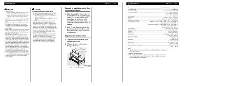
Example of installation on the floor<br />
mat or on the chassis<br />
1. Place the amplifier where it is to be<br />
installed. Insert the supplied tapping<br />
screws (4 × 18 mm) into the screw<br />
holes. Push on the screws with a<br />
screwdriver so they make marks<br />
where the installation holes are to be<br />
located.<br />
2. Drill 2.5 mm diameter holes at the<br />
point marked, and install the amplifier,<br />
either on the carpet or directly<br />
to the chassis.<br />
Replacing the terminal cover<br />
1. Align the unit and terminal cover,<br />
and insert the screw.<br />
2. Tighten the screw with a 4 mm<br />
hexagonal wrench.<br />
Screw<br />
Tapping-screws<br />
(4 × 18 mm)<br />
Terminal Cover<br />
Power source ........................................................................................................ 14.4 V DC (10.8 V to 15.1 V allowable)<br />
Grounding system .......................................................................................................................................... Negative type<br />
Current consumption ...................................................................................................... 39 A (at continuous power, 4 Ω)<br />
Average current drawn* .......................................................................................................... 12 A (4 Ω for one channel)<br />
20 A (2 Ω for one channel)<br />
28 A (1 Ω for one channel)<br />
Fuse (external) ...................................................................................................................................................... 40 A × 2<br />
Dimensions .................................................................................................................... 304 (W) × 56 (H) × 195 (D) mm<br />
Weight .................................................................................................................... 2.9 kg (Leads for wiring not included)<br />
Maximum power output .............................................................................. 800 W × 1 (4 Ω) / 1 200 W × 1 (1 Ω to 2 Ω)<br />
Continuous power (14.4 V) .................................... NORMAL mode: 4 Ω, 20 Hz to 240 Hz, 1.0% THD, 400 W × 1<br />
2 Ω, 100 Hz, 1.0% THD, 600 W × 1<br />
HI-CURRENT mode: 4 Ω, 20 Hz to 240 Hz, 1.0% THD, 150 W × 1<br />
2 Ω, 100 Hz, 1.0% THD, 300 W × 1<br />
1 Ω, 100 Hz, 1.0% THD, 600 W × 1<br />
Load impedance ...................................................................................................................... 4 Ω (1 Ω to 8 Ω allowable)<br />
Frequency response ........................................................................................................ 10 Hz to 240 Hz (+0 dB, –3 dB)<br />
S/N ratio ........................................................................................................................................ 92 dB (IEC-A network)<br />
Distortion .......................................................................................................................................... 0.5 % (10 W, 100 Hz)<br />
Low pass filter ............................................................................................................ Cut off frequency: 40 Hz to 240 Hz<br />
Cut off slope: –18 dB/oct<br />
Subsonic filter (HPF) .............................................................................................................................. Frequency: 20 Hz<br />
Slope: –18 dB<br />
Bass boost ................................................................................................................................................ Frequency: 50 Hz<br />
Level: 0 / 6 / 9 / 12 dB<br />
Gain control .................................................................................................................................... RCA: 400 mV to 6.5 V<br />
SP: 1.6 V to 26 V<br />
Maximum input level / impedance .................................................................................................... RCA: 6.5 V / 22 kΩ<br />
SP: 26 V / 90 kΩ<br />
Note:<br />
• Specifications and the design are subject to possible modification without notice<br />
due to improvements.<br />
*Average current drawn<br />
• The average current drawn is nearly the maximum current drawn by this unit<br />
when an audio signal is input. Use this value when working out total current<br />
drawn by multiple power amplifiers.<br />
Drill a 2.5 mm diameter hole<br />
Floor mat<br />
or chassis


