
Create successful ePaper yourself
Turn your PDF publications into a flip-book with our unique Google optimized e-Paper software.
MaxiMill HFC<br />
'<strong>Feed</strong> matters', rapid milling<br />
EN
CERATIZIT - secrets of success<br />
Secrets of success<br />
• CERATIZIT is your partner for exceptional hard<br />
material solutions. Hard materials and tools<br />
from CERATIZIT - our solutions to complex<br />
problems are an integral part of our customers'<br />
success. Our products guarantee: economy -<br />
long life - speed! And it is precisely this<br />
combination which gives our business partners<br />
a direct competitive advantage.<br />
• Premier performance is only possible through a<br />
total appreciation of the requirements of our<br />
business partners. A performance achieved<br />
through flexible thinking and continuous<br />
dialogue with our customers. A pioneering spirit<br />
and a deep understanding of powder<br />
metallurgy characterize the history of<br />
CERATIZIT. One of the attributes of our<br />
company philosophy is the search for<br />
perfection: target oriented - sustainably -<br />
passionately!<br />
• Intensive research and development activities,<br />
taking into account the precise requirements<br />
and working processes of the customer, are<br />
today's investment for the solutions of tomorrow<br />
- and beyond.<br />
Corporate values<br />
The views and focus of our business<br />
partners matter<br />
Innovative and flexible<br />
thinking matters<br />
Communication matters<br />
Employee development<br />
matters<br />
Professionalism matters<br />
Our environment<br />
matters<br />
Tailored cutting tool solutions<br />
• Cutting materials, coatings, inserts, tooling<br />
systems and machining solutions - all this is<br />
included in the cutting tool division at<br />
CERATIZIT.<br />
• Worldwide well-known companies process<br />
advanced materials applying cutting tool<br />
products from CERATIZIT: from the automotive<br />
industry to the aerospace industry, mechanical<br />
engineering, and tool construction to the oil<br />
industry.<br />
• The basis of these long-term business relations<br />
is the faith of the customers in the extensive<br />
know-how of the carbide specialists.<br />
2
3
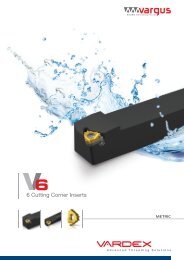
System MaxiMill HFC<br />
Milling system - customer benefits<br />
Extreme face milling<br />
The CERATIZIT solution: MaxiMill HFC<br />
With feed rates up to 3 mm/tooth and closely pitched tools, very high chip<br />
removal rates are achieved.<br />
● Extreme feed rates<br />
● Soft cutting with chip groove M50<br />
● HyperCoat inserts<br />
1 Face milling with maximum feed rate (3 mm per tooth)<br />
2 Ramping for the production of deep pockets<br />
3 Plunge milling for maximum chip removal rates (3 mm per tooth)<br />
normal<br />
close<br />
06 09 12<br />
Milling cutters Ø 16-100 mm<br />
Maximum tool life<br />
HyperCoat coating<br />
CTC5240<br />
CTC5235<br />
CTP1235<br />
CTP2235<br />
CTC3215<br />
SR226+<br />
Application advantages<br />
● Maximum tool life thanks to HyperCoat<br />
coating<br />
● Reduced machining noise and vibration,<br />
light cutting geometries<br />
● Optimal cutting performance with low<br />
depths of cut<br />
● Maximum economy thanks to<br />
4 cutting edges<br />
● <strong>Feed</strong> rate up to 3 mm/tooth<br />
Flexibility thanks to coolant holes with MQL* design<br />
● Central coolant supply in all tools.<br />
● Tapered coolant exit hole for minimum quantity lubrication.<br />
● Optimum position of coolant exit hole close to the<br />
cutting edge<br />
Increased flexibility when choosing the coolant<br />
(air, mist or lubricant).<br />
Reduced tool and work piece heating.<br />
Support for chip evacuation when milling deep pockets.<br />
* MQL = minimum<br />
quantity lubrication<br />
4
MaxiMill HFC<br />
Customer benefits<br />
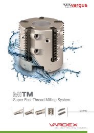
Reduced machining noise and vibration<br />
Light cutting geometries<br />
Extremely positive cutting angle: soft cutting and reduced cutting noise! The cutting forces are mainly in<br />
the axial direction:<br />
Even with long overhang lengths there is almost no vibration, and little stress on the machine spindle.<br />
MaxiMill 211 MaxiMill 274 MaxiMill HFC<br />
3<br />
4<br />
2<br />
1<br />
F res<br />
F res<br />
F res<br />
Shoulder milling system with<br />
approach angle k r = 90°<br />
→ strong radial forces on the tool<br />
and the machine spindle:<br />
Face milling systems with approach<br />
angle k r = 45°<br />
→ the generated forces are divided<br />
into approximately equal components:<br />
<strong>High</strong> feed milling systems with<br />
approach angle k r = 15°<br />
→ the generated axial forces are in<br />
the direction of the machine spindle:<br />
F r >> F a F r = F a F r
Grade overview<br />
Wear resistance / toughness<br />
Wear resistance<br />
10<br />
8<br />
6<br />
4<br />
SR226+<br />
CTP1235<br />
2<br />
0<br />
0 2 4 6 8 10<br />
Toughness<br />
Wear resistance<br />
10<br />
8<br />
CTC5240<br />
CTC5235<br />
6<br />
CTP2235<br />
4<br />
2<br />
0<br />
0 2 4 6 8 10<br />
Toughness<br />
Wear resistance<br />
10<br />
8<br />
6<br />
4<br />
CTC3215<br />
SR226+<br />
2<br />
0<br />
0 2 4 6 8 10<br />
Toughness<br />
6
Grade overview<br />
Grade<br />
designation<br />
CTP1235<br />
CTP2235<br />
SR226+<br />
Standard<br />
designation<br />
Cutting material<br />
Application range<br />
05 15 25 35 45<br />
01 10 20 30 40 50<br />
CTC3215 HC-K15 C<br />
●<br />
HC-P35 P<br />
●<br />
HC-P40 P<br />
○<br />
A R F N S H<br />
CTC5235 HC-M35 C<br />
○●○ ●<br />
CTC5240 HC-M40 C<br />
●<br />
HC-M30 P<br />
○ ○<br />
HC-M40 P<br />
● ○<br />
HC-P25 C<br />
●<br />
HC-M25 C<br />
○<br />
HC-K20 C<br />
●<br />
Steel<br />
Stainless<br />
Cast iron<br />
Non ferrous metals<br />
Heat resistant<br />
Hard materials<br />
01 10 20 30 40 50<br />
05 15 25 35 45<br />
Main application<br />
Extended application<br />
7
Inserts<br />
Shape X<br />
F40 M50 R50<br />
CTC3215<br />
SR226+<br />
CTP1235<br />
CTC5235<br />
CTC5240<br />
CTP2235<br />
(l)<br />
[mm]<br />
Type,<br />
description<br />
d<br />
[mm]<br />
l<br />
[mm]<br />
s<br />
[mm]<br />
l 1<br />
[mm]<br />
r<br />
[mm]<br />
d 1<br />
[mm]<br />
α<br />
[°]<br />
06<br />
XPLX 060305ER-F40 R<br />
1,0<br />
6,35 6,00 2,75<br />
XPLX 060305SR-M50 R 1,0<br />
0,50 2,80 11<br />
09<br />
XDLX 09T308ER-F40 R R<br />
2,4<br />
9,60 9,00 3,97<br />
XDLX 09T308SR-M50 R R R R 1,5<br />
0,80 4,40 15<br />
XOLX 120410ER-F40 R R<br />
2,2<br />
12 XOLX 120410SR-M50 R R R R 12,70 12,00 4,76<br />
1,00 5,50 9<br />
2,2<br />
XOLX 120410SR-R50<br />
R<br />
Steel RRr r<br />
Stainless rrR R<br />
Cast iron R R r<br />
Non ferrous metals<br />
Heat resistant rRRr<br />
Hard materials<br />
l<br />
d<br />
r<br />
l 1<br />
<br />
d 1<br />
s<br />
Main application<br />
Extended application<br />
International CERATIZIT range, for present availability see price list<br />
Ordering example: 10 pieces XPLX 060305ER-F40 CTC5235<br />
CHFC-06/09/12 GHFC-06/09/12 AHFC-09/12<br />
8
Face milling cutters<br />
CHFC-06/-09/-12<br />
0 ° ÷2°<br />
-1,5 ° ÷(-2°)<br />
l 2<br />
Ø d 1<br />
DIN 1835A<br />
Ø d A h6<br />
-B<br />
a<br />
l 1<br />
-A<br />
d 1 Type,<br />
l 1 l 2 d A a n max<br />
[mm] description<br />
[mm] [mm] [mm] [mm] [min -1 ] z<br />
16<br />
CHFC.16.R.02-06-A-40-200 200 40 16<br />
4.600 2<br />
CHFC.16.R.02-06-B-40 89 40 16 17.300 2<br />
CHFC.20.R.03-06-A-50-225 225 50 20 4.200 3<br />
20<br />
CHFC.20.R.03-06-B-50 101 50 20 14.500 3<br />
0,8<br />
CHFC.25.R.04-06-A-50-225 225 50 25 4.600 4<br />
25<br />
CHFC.25.R.04-06-B-50 107 50 25 15.600 4<br />
32<br />
CHFC.32.R.05-06-A25-60-225 225 60 25 3.900 5<br />
CHFC.32.R.05-06-B25-60 117 60 25 11.000 5<br />
25<br />
CHFC.25.R.02-09-A-50-225 225 50 25<br />
9.000 2<br />
CHFC.25.R.03-09-A-50-225 225 50 25 1 9.000 3<br />
CHFC.32.R.03-09-A-63-250 250 63 32 8.100 3<br />
32<br />
CHFC.32.R.02-12-A-63-250 250 63 32<br />
6.480 2<br />
2<br />
35 CHFC.35.R.03-12-A-63-250 250 63 32 6.408 3<br />
XP.. 0603<br />
XD.. 09T3<br />
XO.. 1204<br />
Ordering example: 1 piece CHFC.16.R.02-06-A-40-200<br />
Supply details: cutter body and clamping screws for inserts<br />
d 1<br />
[mm]<br />
X_LX 0603 16 - 32 7883204/M2,5X5/T08 7724106/TORX T08 DMSD 1,2Nm/SORT T08<br />
X_LX 09T3 25 7722111/M3,5X7,2/T15 7724103/TORX T15 DMSD 3,2Nm/SORT T15<br />
X_LX 09T3 32 7883209/M3,5X8,6/T15 7724103/TORX T15 DMSD 3,2Nm/SORT T15<br />
X_LX 1204 32 - 35 7822114/M4,5X10,5/T20 7724104/TORX T20 DMSD 5,0Nm/SORT T20<br />
XP.. 0603 XD.. 09T3 XO.. 1204<br />
9
Face milling cutters<br />
GHFC-06/-09/-12<br />
0 ° ÷2°<br />
-1,5 ° ÷(-2°)<br />
SW<br />
Ø d 1<br />
Ø d G<br />
Ø d A<br />
a<br />
l 2<br />
d 1 Type,<br />
l 2 d A d G a n max<br />
[mm] description<br />
[mm] [mm] [mm] [mm] [min -1 ] z<br />
16 GHFC.16.R.02-06-27 27 8,5 8<br />
20.800 2<br />
20 GHFC.20.R.03-06-33 33 10,5 10 19.800 3<br />
0,8<br />
25 GHFC.25.R.04-06-35 35 12,5 12 18.700 4<br />
32 GHFC.32.R.05-06-35 35 17,0 16 22.000 5<br />
GHFC.25.R.02-09 35 12,5 12<br />
30.000 2<br />
25<br />
GHFC.25.R.03-09 35 12,5 12 30.000 3<br />
1<br />
GHFC.32.R.03-09 35 17,0 16 27.000 3<br />
32<br />
GHFC.32.R.02-12 35 17,0 16<br />
21.600 2<br />
2<br />
35 GHFC.35.R.03-12 35 17,0 16 21.360 3<br />
XP.. 0603<br />
XD.. 09T3<br />
XO.. 1204<br />
Ordering example: 1 piece GHFC.16.R.02-06-27<br />
Supply details: cutter body and clamping screws for inserts<br />
n max = depends on the overhang and number of interfaces in the complete tool<br />
d 1<br />
[mm]<br />
X_LX 0603 16 - 32 7883204/M2,5X5/T08 7724106/TORX T08 DMSD 1,2Nm/SORT T08<br />
X_LX 09T3 25 7722111/M3,5X7,2/T15 7724103/TORX T15 DMSD 3,2Nm/SORT T15<br />
X_LX 09T3 32 7883209/M3,5X8,6/T15 7724103/TORX T15 DMSD 3,2Nm/SORT T15<br />
X_LX 1204 32 - 35 7822114/M4,5X10,5/T20 7724104/TORX T20 DMSD 5,0Nm/SORT T20<br />
XP.. 0603 XD.. 09T3 XO.. 1204<br />
10
Face milling cutters<br />
AHFC-09/-12<br />
0 ° ÷2°<br />
-1,5 ° ÷(-2°)<br />
Ø d<br />
Ø d A<br />
Ø d 1<br />
a<br />
h<br />
d 1 Type,<br />
d A a d h n max<br />
[mm] description<br />
[mm] [mm] [mm] [mm] [min -1 ] z<br />
32 AHFC.32.R.03-09 16<br />
38 40 27.000 3<br />
35 AHFC.35.R.04-09 16 38 40 26.700 4<br />
40 AHFC.40.R.04-09 16 38 40 26.400 4<br />
42 AHFC.42.R.05-09 16 38 40 26.100 5<br />
1<br />
50 AHFC.50.R.05-09 22 43 40 23.500 5<br />
52 AHFC.52.R.06-09 22 43 40 23.000 6<br />
63 AHFC.63.R.06-09 22 48 40 20.500 6<br />
66 AHFC.66.R.07-09 22 48 40 20.000 7<br />
40 AHFC.40.R.03-12 16<br />
38 40 21.120 3<br />
42 AHFC.42.R.04-12 16 38 40 20.880 4<br />
50 AHFC.50.R.04-12 22 43 40 18.800 4<br />
52 AHFC.52.R.05-12 22 43 40 18.400 5<br />
63 AHFC.63.R.05-12 22 2 48 40 16.400 5<br />
66 AHFC.66.R.06-12 22 48 40 16.000 6<br />
80 AHFC.80.R.07-12 27 58 50 14.000 7<br />
100 AHFC.100.R.08-12 32 78 50 12.000 8<br />
XD.. 09T3<br />
XO.. 1204<br />
Ordering example: 1 piece AHFC.32.R.03-09<br />
Supply details: cutter body and clamping screws for inserts<br />
d 1<br />
[mm]<br />
XD_X 09T3 32 - 42 7883209/M3,5X8,6/T15 7724103/TORX T15 DMSD 3,2Nm/SORT T15 7818267/M8,0x30,0<br />
XD_X 09T3 50 - 63 7883209/M3,5X8,6/T15 7724103/TORX T15 DMSD 3,2Nm/SORT T15<br />
XO_X 1204 40 - 42 7822114/M4,5X10,5/T20 7724104/TORX T20 DMSD 5,0Nm/SORT T20 7818267/M8,0x30,0<br />
XO_X 1204 50 - 100 7822114/M4,5X10,5/T20 7724104/TORX T20 DMSD 5,0Nm/SORT T20<br />
XD_X 09T3 32 - 42 S4/SW4<br />
XO_X 1204 40 - 42 S4/SW4<br />
XD.. 09T3 XO.. 1204<br />
11
Cutting data<br />
Tool, material<br />
v c (m/min) f z (mm) a p (mm) v c (m/min) f z (mm) a p (mm) v c (m/min) f z (mm) a p (mm)<br />
MaxiMill HFC-06<br />
280 - 100 – – – 0,1 - 1,5 0,1 - 0,4 – 0,1 - 1,0 0,1 - 0,8<br />
260 - 140 – – – 0,1 - 1,5 0,1 - 0,4 – 0,1 - 1,0 0,1 - 0,8<br />
230 - 110 – – – 0,1 - 1,5 0,1 - 0,4 – 0,1 - 1,0 0,1 - 0,8<br />
MaxiMill HFC-09<br />
280 - 100 – – – 0,1 - 2,5 0,1 - 0,5 – 0,1 - 1,5 0,5 - 1,0<br />
260 - 140 – – – 0,1 - 2,5 0,1 - 0,5 – 0,1 - 1,5 0,5 - 1,0<br />
230 - 110 – – – 0,1 - 2,5 0,1 - 0,5 – 0,1 - 1,5 0,5 - 1,0<br />
MaxiMill HFC-12<br />
280 - 100 – – – 0,1 - 3,0 0,5 - 1,2 – 0,1 - 2,0 1,0 - 2,0<br />
260 - 140 – – – 0,1 - 3,0 0,5 - 1,2 – 0,1 - 2,0 1,0 - 2,0<br />
230 - 110 – – – 0,1 - 3,0 0,5 - 1,2 – 0,1 - 2,0 1,0 - 2,0<br />
Recommendations for economic milling<br />
HFC<br />
a p [mm]<br />
2,5<br />
2<br />
1,5<br />
l [mm]<br />
06<br />
09<br />
12<br />
a p<br />
0,1 - 0,8<br />
0,1 - 1<br />
0,5 - 2<br />
f z<br />
1,5 - 0,10<br />
2,5 - 0,10<br />
3,0 - 0,25<br />
1<br />
0,5<br />
0 0,5 1 1,5 2 2,5 3<br />
f z [mm]<br />
12
13
Cutting data<br />
Grades / materials<br />
A<br />
R<br />
F<br />
N<br />
S<br />
H<br />
Work piece<br />
material<br />
Type of treatment / alloy<br />
annealed<br />
≤ 0,15% C<br />
Non alloyed steel annealed<br />
0,15% - 0,45% C<br />
tempered<br />
≥ 0,45% C<br />
Low alloyed steel<br />
annealed<br />
tempered<br />
tempered<br />
<strong>High</strong> alloyed steel<br />
annealed<br />
tempered<br />
Stainless steel<br />
annealed<br />
ferritic<br />
tempered<br />
martensitic<br />
annealed<br />
ferritic / martensitic<br />
Stainless steel<br />
quenched<br />
austenitic<br />
quenched<br />
duplex<br />
hardened<br />
martensitic / austenitic<br />
pearlitic / ferritic<br />
Grey cast iron<br />
pearlitic / martensitic<br />
Spheroidal<br />
cast iron<br />
ferritic<br />
pearlitic<br />
ferritic<br />
Malleable cast iron<br />
pearlitic<br />
Aluminium<br />
wrought alloys<br />
non hardened<br />
hardened<br />
non hardened<br />
< 12% Si<br />
Aluminium<br />
cast alloys<br />
hardened<br />
< 12% Si<br />
non hardened<br />
> 12% Si<br />
machining alloy stock (1% Pb)<br />
Copper and<br />
brass, red bronze<br />
copper alloys (bronze,<br />
brass)<br />
bronze<br />
lead-free copper and electrolytic copper<br />
thermosetting plastics<br />
Non-metallic<br />
materials<br />
fi bre reinforced plastics<br />
hard rubber<br />
annealed<br />
Fe base<br />
hardened<br />
Fe base<br />
Heat resistant<br />
alloys<br />
annealed<br />
Ni or Co base<br />
hardened<br />
Ni or Co base 30 - 58 HRC<br />
cast Ni or Co base 1500 - 2200 Nmm 2<br />
Titanium alloys<br />
Ni or Co base<br />
alpha + beta alloys<br />
Tempered steel<br />
hardened and tempered<br />
hardened and tempered<br />
Chilled castings cast<br />
Tempered cast iron hardened and tempered<br />
* Rm = ultimate tensile strength, measured in MPa<br />
VDI 3323<br />
group<br />
Hardness<br />
HB<br />
1 125<br />
2 150 - 250<br />
3 300<br />
6 180<br />
7 / 8 250 - 300<br />
9 350<br />
10 200<br />
11 350<br />
12 200<br />
13 325<br />
14 200<br />
14 180<br />
14 230 - 260<br />
14 330<br />
15 180<br />
16 260<br />
17 160<br />
18 –<br />
19 130<br />
20 230<br />
21 60<br />
22 100<br />
23 80<br />
24 90<br />
25 130<br />
26 –<br />
27 90<br />
28 100<br />
29 100<br />
29 –<br />
29 –<br />
30 –<br />
31 200<br />
32 280<br />
33 250<br />
34 –<br />
35 –<br />
36 R m 440*<br />
37 R m 1050*<br />
38 55 HRC<br />
39 60 HRC<br />
40 400<br />
40 55 HRC<br />
14
Cutting data<br />
Grades / materials<br />
Coated carbide<br />
CTC3215 CTP1235 CTP2235 SR226+<br />
v c [m/min] v c [m/min] v c [m/min] v c [m/min] v c [m/min] v c [m/min] v c [m/min] v c [m/min]<br />
– – 100-220 70-180 150 - 260 90 - 180 210 - 350 130 - 200<br />
– – 100-220 70-180 150 - 260 90 - 180 170 - 320 110 - 180<br />
– – 100-220 70-180 150 - 260 90 - 180 150 - 280 90 - 150<br />
– – 80-220 70-170 80 - 220 70 - 160 150 - 250 80 - 140<br />
– – 80-220 70-170 80 - 220 70 - 160 140 - 210 60 - 120<br />
– – 80-220 70-170 80 - 220 70 - 160 100 - 180 60 - 110<br />
– – 80-180 60-140 90 - 180 70 - 140 140 - 210 60 - 110<br />
– – 80-180 60-140 90 - 180 70 - 140 100 - 170 60 - 100<br />
– – 70-180 60-140 70 - 180 60 - 140 140 - 190 80 - 140<br />
– – 70-180 60-140 70 - 180 60 - 140 100 - 170 70 - 120<br />
– – 60-200 40-140 60 - 200 60 - 140 110 - 200 –<br />
– – 60-200 40-140 60 - 200 60 - 140 120 - 210 –<br />
– – 60-200 40-140 60 - 200 60 - 140 – –<br />
– – 60-200 40-140 60 - 200 60 - 140 80 - 140 –<br />
180 - 350 180 - 350 – – – – 160 - 220 120 - 180<br />
140 - 280 140 - 280 – – – – 100 - 170 80 - 150<br />
130 - 250 130 - 250 – – – – 100 - 200 80 - 170<br />
100 - 200 100 - 200 – – – – 90 - 180 70 - 140<br />
150 - 320 150 - 320 – – – – 90 - 180 70 - 140<br />
120 - 250 120 - 250 – – – – 80 - 160 70 - 130<br />
– – – – – – – –<br />
– – – – – – – –<br />
– – – – – – – –<br />
– – – – – – – –<br />
– – – – – – – –<br />
– – – – – – – –<br />
– – – – – – – –<br />
– – – – – – – –<br />
– – – – – – – –<br />
– – – – – – – –<br />
– – – – – – – –<br />
– – – – – – – –<br />
– – – – – 20-60 – 60 - 90<br />
– – – – – 20-60 – 60 - 90<br />
– – – – – 20-60 – –<br />
– – – – – 20-30 – –<br />
– – – – – 20-30 – –<br />
– – – – – 40-70 – –<br />
– – – – – 20-40 – –<br />
– – – – – – – –<br />
– – – – – – – –<br />
– – – – – – 70 - 130 –<br />
– – – – – – – –<br />
Recommended application<br />
Possible application<br />
15
Cutting data<br />
Grades / materials<br />
A<br />
R<br />
F<br />
N<br />
S<br />
H<br />
Work piece<br />
material<br />
Type of treatment / alloy<br />
annealed<br />
≤ 0,15% C<br />
Non alloyed steel annealed<br />
0,15% - 0,45% C<br />
tempered<br />
≥ 0,45% C<br />
Low alloyed steel<br />
annealed<br />
tempered<br />
tempered<br />
<strong>High</strong> alloyed steel<br />
annealed<br />
tempered<br />
Stainless steel<br />
annealed<br />
ferritic<br />
tempered<br />
martensitic<br />
annealed<br />
ferritic / martensitic<br />
Stainless steel<br />
quenched<br />
austenitic<br />
quenched<br />
duplex<br />
hardened<br />
martensitic / austenitic<br />
pearlitic / ferritic<br />
Grey cast iron<br />
pearlitic / martensitic<br />
Spheroidal<br />
cast iron<br />
ferritic<br />
pearlitic<br />
ferritic<br />
Malleable cast iron<br />
pearlitic<br />
Aluminium<br />
wrought alloys<br />
non hardened<br />
hardened<br />
non hardened<br />
< 12% Si<br />
Aluminium<br />
cast alloys<br />
hardened<br />
< 12% Si<br />
non hardened<br />
> 12% Si<br />
machining alloy stock (1% Pb)<br />
Copper and<br />
brass, red bronze<br />
copper alloys (bronze,<br />
brass)<br />
bronze<br />
lead-free copper and electrolytic copper<br />
thermosetting plastics<br />
Non-metallic<br />
materials<br />
fi bre reinforced plastics<br />
hard rubber<br />
annealed<br />
Fe base<br />
hardened<br />
Fe base<br />
Heat resistant<br />
alloys<br />
annealed<br />
Ni or Co base<br />
hardened<br />
Ni or Co base 30 - 58 HRC<br />
cast Ni or Co base 1500 - 2200 Nmm 2<br />
Titanium alloys<br />
Ni or Co base<br />
alpha + beta alloys<br />
Tempered steel<br />
hardened and tempered<br />
hardened and tempered<br />
Chilled castings cast<br />
Tempered cast iron hardened and tempered<br />
* Rm = ultimate tensile strength, measured in MPa<br />
VDI 3323<br />
group<br />
Hardness<br />
HB<br />
1 125<br />
2 150 - 250<br />
3 300<br />
6 180<br />
7 / 8 250 - 300<br />
9 350<br />
10 200<br />
11 350<br />
12 200<br />
13 325<br />
14 200<br />
14 180<br />
14 230 - 260<br />
14 330<br />
15 180<br />
16 260<br />
17 160<br />
18 –<br />
19 130<br />
20 230<br />
21 60<br />
22 100<br />
23 80<br />
24 90<br />
25 130<br />
26 –<br />
27 90<br />
28 100<br />
29 100<br />
29 –<br />
29 –<br />
30 –<br />
31 200<br />
32 280<br />
33 250<br />
34 –<br />
35 –<br />
36 R m 440*<br />
37 R m 1050*<br />
38 55 HRC<br />
39 60 HRC<br />
40 400<br />
40 55 HRC<br />
16
Cutting data<br />
Grades / materials<br />
Coated carbide<br />
CTC5235<br />
CTC5240<br />
v c [m/min] v c [m/min] v c [m/min] v c [m/min]<br />
150 - 260 90 - 180 – –<br />
150 - 260 90 - 180 – –<br />
150 - 260 90 - 180 – –<br />
80 - 220 70 - 160 – –<br />
80 - 220 70 - 160 – –<br />
80 - 220 70 - 160 – –<br />
90 - 180 70 - 140 – –<br />
90 - 180 70 - 140 – –<br />
70 - 180 60 - 140 – –<br />
70 - 180 60 - 140 – –<br />
220 - 350 – – –<br />
150 - 240 – – –<br />
80 - 160 60 - 140 – –<br />
80 - 200 60 - 180 – –<br />
– – – –<br />
– – – –<br />
– – – –<br />
– – – –<br />
– – – –<br />
– – – –<br />
– – – –<br />
– – – –<br />
– – – –<br />
– – – –<br />
– – – –<br />
– – – –<br />
– – – –<br />
– – – –<br />
– – – –<br />
– – – –<br />
– – – –<br />
– – – –<br />
– – – 30 - 250<br />
– – – 10 - 60<br />
– – – 20 - 60<br />
– – – 10 - 50<br />
– – – 10 - 40<br />
– – – 60 - 120<br />
– – – 40 - 80<br />
– – – –<br />
– – – –<br />
– – – –<br />
– – – –<br />
Recommended application<br />
Possible application<br />
17
Application data<br />
HFC-06<br />
Helical plunge milling<br />
D M<br />
D max [mm] = maximum diameter for flat bottom ground<br />
D min [mm] = minimum hole diameter<br />
D M = D max - d 1 or D min - d 1<br />
d 1<br />
[mm]<br />
D max<br />
[mm]<br />
D min<br />
[mm]<br />
α R max<br />
[°]<br />
16 31 22 4,5°<br />
20 39 30 2,3°<br />
25 49 40 1,3°<br />
32 63 54 0,9°<br />
Axial plunging<br />
a p [mm] = D M x π x tan α R<br />
d 1<br />
[mm]<br />
X max [mm]<br />
16 - 32 0,5<br />
Angled ramping<br />
d 1<br />
[mm] α R max [°]<br />
16 5,9°<br />
20 3,2°<br />
25 2,0°<br />
32 1,3°<br />
d 1<br />
18
Application data<br />
HFC-06<br />
Depth of cut and remaining material<br />
r<br />
R = 1,2 mm<br />
l<br />
[mm]<br />
B<br />
[mm]<br />
r<br />
[mm]<br />
a p max<br />
[mm]<br />
6,35 4,3 0,5 0,8<br />
l = 6,35 mm<br />
R = programmed radius<br />
B<br />
ap max<br />
Profile when shoulder and slot milling<br />
f z ≥ 0.4 / tooth<br />
<br />
<br />
recommended<br />
Width of cut for flat surfaces<br />
d 1<br />
[mm]<br />
X<br />
[mm]<br />
B<br />
[mm]<br />
16 - 32 d 1 -(2 x B) 4,3<br />
X<br />
B<br />
Ø d 1<br />
Engagement data when plunge milling<br />
Z max<br />
Y<br />
Y [mm] initial [mm] min [mm] max [mm]<br />
Z max f z<br />
max<br />
[mm]<br />
5,3 0,10 0,08 0,15 < 0,7 x d 1<br />
Tool offset with optimum overlap<br />
Tool offset for unstable conditions<br />
Y<br />
Z max Z max /2<br />
Y<br />
19
Application data<br />
HFC-09<br />
Helical plunge milling<br />
D M<br />
D max [mm] = maximum diameter for flat bottom ground<br />
D min [mm] = minimum hole diameter<br />
D M = D max - d 1 or D min - d 1<br />
d 1<br />
[mm]<br />
D max<br />
[mm]<br />
D min<br />
[mm]<br />
α R max<br />
[°]<br />
25 48 35 3,1<br />
32 62 49 1,7<br />
35 68 55 1,4<br />
40 78 65 1,0<br />
42 82 69 0,9<br />
50 98 85 0,8<br />
52 102 89 0,7<br />
63 124 111 0,7<br />
66 130 117 0,6<br />
Axial plunging<br />
a p [mm] = D M x π x tan α R<br />
d 1<br />
[mm]<br />
X max [mm]<br />
25 - 66 0,75<br />
Angled ramping<br />
d 1<br />
d 1<br />
[mm] α R max [°]<br />
25 3,6<br />
32 2,0<br />
35 1,6<br />
40 1,2<br />
42 1,1<br />
50 0,9<br />
52 0,8<br />
63 0,8<br />
66 0,7<br />
20
Application data<br />
HFC-09<br />
Depth of cut and remaining material<br />
r<br />
R=2mm<br />
l<br />
[mm]<br />
B<br />
[mm]<br />
r<br />
[mm]<br />
a p max<br />
[mm]<br />
9 5,9 0,8 1<br />
l=9mm<br />
R = programmed radius<br />
B<br />
ap max<br />
Profile when shoulder and slot milling<br />
f z ≥ 0.5 / tooth<br />
<br />
<br />
recommended<br />
Width of cut for flat surfaces<br />
d 1<br />
[mm]<br />
X<br />
[mm]<br />
B<br />
[mm]<br />
25-66 d 1 -(2 x B) 5,9<br />
X<br />
B<br />
Ø d 1<br />
Engagement data when plunge milling<br />
Z max<br />
Y<br />
Y [mm] initial [mm] min [mm] max [mm]<br />
Z max f z<br />
max<br />
[mm]<br />
7,5 0,10 0,08 0,15 < 0,7 x d 1<br />
Tool offset with optimum overlap<br />
Tool offset for unstable conditions<br />
Y<br />
Z max Z max /2<br />
Y<br />
21
Application data<br />
HFC-12<br />
Helical plunge milling<br />
D M<br />
D max [mm] = maximum diameter for flat bottom ground<br />
D min [mm] = minimum hole diameter<br />
D M = D max - d 1 or D min - d 1<br />
d 1<br />
[mm]<br />
D max<br />
[mm]<br />
D min<br />
[mm]<br />
α R max<br />
[°]<br />
32 62 44 6,1<br />
35 68 50 3,7<br />
40 78 60 2,5<br />
42 82 64 2,3<br />
50 98 80 1,3<br />
52 102 84 1,3<br />
63 124 106 0,9<br />
66 130 112 0,9<br />
80 158 140 1,1<br />
100 198 180 0,6<br />
Axial plunging<br />
a p [mm] = D M x π x tan α R<br />
d 1<br />
[mm]<br />
X max [mm]<br />
32 - 100 1,15<br />
Angled ramping<br />
d 1<br />
d 1<br />
[mm] α R max [°]<br />
32 7,2<br />
35 4,4<br />
40 2,9<br />
42 2,7<br />
50 1,5<br />
52 1,5<br />
63 1,1<br />
66 1,1<br />
80 1,3<br />
100 0,7<br />
22
Application data<br />
HFC-12<br />
Depth of cut and remaining material<br />
r<br />
R=3mm<br />
l<br />
[mm]<br />
B<br />
[mm]<br />
r<br />
[mm]<br />
a p max<br />
[mm]<br />
12 8,3 1,0 2<br />
l=12mm<br />
R = programmed radius<br />
B<br />
ap max<br />
Profile when shoulder and slot milling<br />
f z ≥ 0.6 / tooth<br />
<br />
<br />
recommended<br />
Width of cut for flat surfaces<br />
d 1<br />
[mm]<br />
X<br />
[mm]<br />
B<br />
[mm]<br />
32 - 100 d 1 -(2 x B) 8,3<br />
X<br />
B<br />
Ø d 1<br />
Engagement data when plunge milling<br />
Z max<br />
max z<br />
Y max<br />
[mm] initial [mm] min [mm] max [mm] [mm]<br />
Y<br />
10 0,15 0,10 0,20 < 0,7 x d 1<br />
Tool offset with optimum overlap<br />
Tool offset for unstable conditions<br />
Y<br />
Z max Z max /2<br />
Y<br />
23
24
25
26
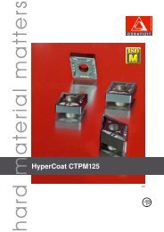
CERATIZIT worldwide<br />
CERATIZIT worldwide<br />
• Production sites in the three big economic<br />
areas with a worldwide network of CERATIZIT<br />
sales and support engineers plus many<br />
CERATIZIT distribution partners guarantee<br />
customer vicinity.<br />
• We maintain the dialogue with our customers<br />
and strive for long-term partnerships.<br />
Find your personal distribution partner at:<br />
www.ceratizit.com<br />
CERATIZIT worldwide production sites and support centres<br />
CERATIZIT worldwide distribution partner network<br />
CERATIZIT worldwide<br />
Parent company in<br />
Luxembourg<br />
CERATIZIT Luxembourg Sàrl<br />
Route de Holzem 101<br />
L-8232 Mamer<br />
Tel.: +352 312 085-1<br />
Fax: +352 311 911<br />
E-mail: info@ceratizit.com<br />
www.ceratizit.com<br />
Contact for further information:<br />
CERATIZIT Austria Gesellschaft m.b.H.<br />
A-6600 Reutte/Tyrol<br />
Tel.: +43 (5672) 200-0<br />
Fax: +43 (5672) 200-502<br />
E-mail: info.austria@ceratizit.com<br />
www.ceratizit.com<br />
27
448<br />
7001692<br />
MA-PRO-0448-EN-08/12-D<br />
We reserve the right to make technical changes for<br />
improvement of the product.