PC 5400 PC 5500 - jewuwa
PC 5400 PC 5500 - jewuwa
PC 5400 PC 5500 - jewuwa

You also want an ePaper? Increase the reach of your titles
YUMPU automatically turns print PDFs into web optimized ePapers that Google loves.
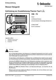
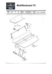
Mounting monitor<br />
A Never install the monitor in an area where the head could impact in case of an<br />
accident!<br />
A Observe safety standards concerning the driver’s field of vision and airbag inflation<br />
area!<br />
The monitor can be fastened with a support which is available on the market for<br />
accessories. An MR 6000 can be installed in a DIN slot as a display unit.<br />
Depending on the type of monitor (4:3 or 16:9 display) you use you can select the<br />
rectification for guidance pictograms. The system is adjusted to a 16:9 diplay by factory<br />
default.<br />
English<br />
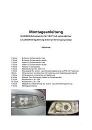
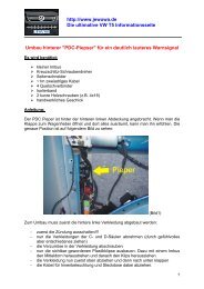
Installing holder for the remote control (optional), ill. 9 - 10<br />
Mounting on angle bracket<br />
Screw holder to angle bracket. Either insert angle bracket into an available slot or<br />
screw it in place.<br />
Mounting with adhesive plate<br />
Snap holder onto plastic plate. Remove protective paper from adhesive tape. Stick<br />
holder with adhesive plate onto mounting surface and press firmly.<br />
Note: Mounting temperature should be at least 15 degrees centigrade to ensure the<br />
full adhesive effect of the tape.<br />
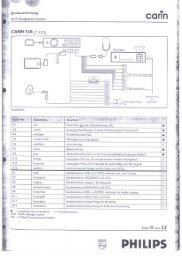
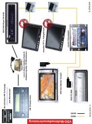
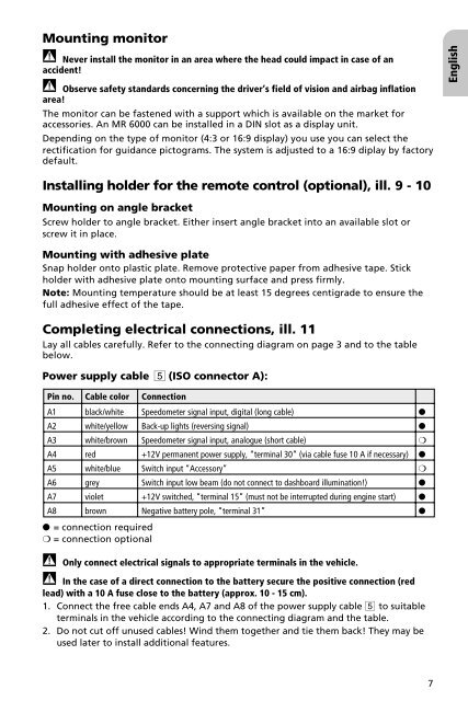
Completing electrical connections, ill. 11<br />
Lay all cables carefully. Refer to the connecting diagram on page 3 and to the table<br />
below.<br />
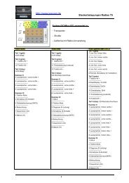
Power supply cable 5 (ISO connector A):<br />
Pin no. Cable color Connection<br />
A1 black/white Speedometer signal input, digital (long cable) ●<br />
A2 white/yellow Back-up lights (reversing signal) ●<br />
A3 white/brown Speedometer signal input, analogue (short cable) ❍<br />
A4 red +12V permanent power supply, “terminal 30” (via cable fuse 10 A if necessary) ●<br />
A5 white/blue Switch input “Accessory” ❍<br />
A6 grey Switch input low beam (do not connect to dashboard illumination!) ●<br />
A7 violet +12V switched, “terminal 15” (must not be interrupted during engine start) ●<br />
A8 brown Negative battery pole, “terminal 31” ●<br />
● = connection required<br />
❍ = connection optional<br />
A Only connect electrical signals to appropriate terminals in the vehicle.<br />
A In the case of a direct connection to the battery secure the positive connection (red<br />
lead) with a 10 A fuse close to the battery (approx. 10 - 15 cm).<br />
1. Connect the free cable ends A4, A7 and A8 of the power supply cable 5 to suitable<br />
terminals in the vehicle according to the connecting diagram and the table.<br />
2. Do not cut off unused cables! Wind them together and tie them back! They may be<br />
used later to install additional features.<br />
7