USER MANUAL INTEK HR-2800 - Free
USER MANUAL INTEK HR-2800 - Free
USER MANUAL INTEK HR-2800 - Free

You also want an ePaper? Increase the reach of your titles
YUMPU automatically turns print PDFs into web optimized ePapers that Google loves.
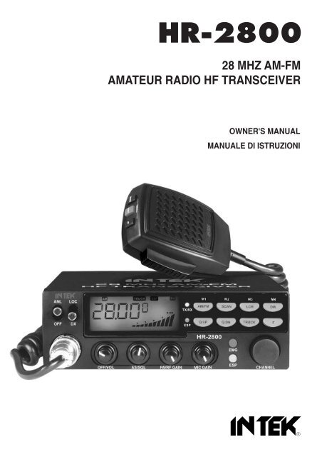
<strong>HR</strong>-<strong>2800</strong><br />
28 MHZ AM-FM<br />
AMATEUR RADIO HF TRANSCEIVER<br />
OWNER'S <strong>MANUAL</strong><br />
<strong>MANUAL</strong>E DI ISTRUZIONI
Declaration of Conformity<br />
EC Certificate of Conformity<br />
(to EC Directive 2006/95, 2004/108, 99/5)<br />
DECLARATION OF CONFORMITY<br />
With the present declaration, we certify that the following products :<br />
<strong>INTEK</strong> <strong>HR</strong>-<strong>2800</strong><br />
comply with all the technical regulations applicable to the above mentioned products<br />
in accordance with the EC Directives 2006/95/EC, 2004/108/EC, 99/5/EC.<br />
Type of product :<br />
28 MHz HF Amateur Radio Equipment<br />
Details of applied standards : EN 301 783-2 V1.2.1, EN 301 489-1<br />
EN 301 489-15, EN 60065<br />
Manufacturer :<br />
<strong>INTEK</strong> S.R.L.<br />
Via G. Marconi, 16<br />
20090 Segrate, Italy<br />
Tel. 39-02-26950451 / Fax. 39-02-26952185<br />
E-mail : intek.com@intek-com.it<br />
Contact Reference :<br />
Armando Zanni<br />
Tel. 39-02-26950451 / Fax. 39-02-26952185<br />
E-mail : intek.com@intek-com.it<br />
Segrate, 14/06/2011<br />
dr. Vittorio Zanetti<br />
(General Manager)<br />
NOTICE !<br />
It is recommended to carefully read this owner’s manual before using the product. This will also help to prevent<br />
illegal use of the radio in violation of the regulations valid in the country where the product is used, as well as to<br />
avoid causing possible interferences to other services.<br />
CH<br />
RoHS<br />
2002/95/EC
Index - Introduction - Content of the packaging<br />
Index . . . . . . . . . . . . . . . . . . . . . . . . . . . . . . . . . . . . . . . . . . . . . . . . . . . . . . . . . . . . . . . . . . . . . . . . . . . . . .1<br />
Introduction - Content of the packaging . . . . . . . . . . . . . . . . . . . . . . . . . . . . . . . . . . . . . . . . . . . . . . . . .1<br />
Controls and operation . . . . . . . . . . . . . . . . . . . . . . . . . . . . . . . . . . . . . . . . . . . . . . . . . . . . . . . . . . . 2 - 9<br />
Installation . . . . . . . . . . . . . . . . . . . . . . . . . . . . . . . . . . . . . . . . . . . . . . . . . . . . . . . . . . . . . . . . . . . . . 10-11<br />
User Information . . . . . . . . . . . . . . . . . . . . . . . . . . . . . . . . . . . . . . . . . . . . . . . . . . . . . . . . . . . . . . . . . . 11<br />
Specifications . . . . . . . . . . . . . . . . . . . . . . . . . . . . . . . . . . . . . . . . . . . . . . . . . . . . . . . . . . . . . . . . . . . . . 12<br />
DC-DC Converter Diagram . . . . . . . . . . . . . . . . . . . . . . . . . . . . . . . . . . . . . . . . . . . . . . . . . . . . . . . . . . . . I<br />
ESP Compander Diagram - CTCSS Diagram . . . . . . . . . . . . . . . . . . . . . . . . . . . . . . . . . . . . . . . . . . . . II<br />
PCB - Main Board & CPU Board . . . . . . . . . . . . . . . . . . . . . . . . . . . . . . . . . . . . . . . . . . . . . . . . . . . III - IV<br />
Diagram . . . . . . . . . . . . . . . . . . . . . . . . . . . . . . . . . . . . . . . . . . . . . . . . . . . . . . . . . . . . . . . . . . . . . . .V- VI<br />
Block Diagram . . . . . . . . . . . . . . . . . . . . . . . . . . . . . . . . . . . . . . . . . . . . . . . . . . . . . . . . . . . . . . . . VII-VIII<br />
English<br />
NOTICE !<br />
This radio is an Amateur Radio HF transceiver, designed to work on the 28 MHz frequency band reserved to<br />
Amateur Radio communication. This transceiver has been manufactured and factory programmed, in order<br />
for the user to operate the radio immediately after purchase. The radio covers the 28 MHz (10-Meter)<br />
Amateur Radio HF frequency band (frequency range 28.000-29.700 KHz). The manufacturer is not<br />
responsible for any modification to the hardware or software of the product, which might possibly cause the<br />
radio to operate illegally and/or out of this frequency range.<br />
Congratulations!<br />
Congratulations for selecting and purchasing a <strong>INTEK</strong> quality product. <strong>INTEK</strong> <strong>HR</strong>-<strong>2800</strong> is a 10-Meter band Amateur<br />
Radio transceiver using advanced hardware and software design. This transceiver includes a number of advanced<br />
functions and systems, therefore it is definitely necessary to carefully read this owner’s manual before using the radio.<br />
With a correct use of the product in accordance with the operating method described in this manual, the product will offer<br />
a trouble free use for many years. <strong>INTEK</strong> is constantly engaged to develop and provide quality products meeting the<br />
customers requirements, however any suggestion or comments on this product that might help us to improve quality are<br />
warmly welcome.<br />
Content of the packaging<br />
Please check that all the following items are contained in the packaging :<br />
Main unit (transceiver)<br />
DC power cord with fuse holder and fuse<br />
Dynamic microphone<br />
Car mounting bracket<br />
Car mounting bracket accessories (hardware, knobs, etc.)<br />
Microphone bracket<br />
Owner’s manual<br />
- 1 -
Controls and operation<br />
English<br />
Front panel<br />
1 2 3 4 5 6 7 8 9<br />
ANL<br />
LOC<br />
C E<br />
TX/RX<br />
M1<br />
M2 M3 M4<br />
AM/FM SCAN LCR DW<br />
10<br />
OFF<br />
DX<br />
ESP<br />
Q.UP Q.DN TRUCK<br />
<strong>HR</strong>-<strong>2800</strong><br />
F<br />
11<br />
12<br />
EMG<br />
OFF/VOL<br />
AS/SQL<br />
PA/RF GAIN<br />
MIC GAIN<br />
ESP<br />
CHANNEL<br />
21 20<br />
19<br />
18 17 16 15 14<br />
13<br />
1. ANL-OFF Selector<br />
This selector enables the ANL function (Automatic Noise Limited). The ANL reduces electric and electromagnetic noise<br />
on the operating frequency. Move the selector to ANL to enable the Automatic Noise Limiter and move it to OFF to<br />
disable it.<br />
2. LOC-DX Selector<br />
This selector enables the LOC function (Local), in order to attenuate the strength of the incoming signals. The attenuator<br />
is useful in case of very strong incoming signals from local stations that, due to the high signal level, might cause<br />
distortion and poor quality of the received signals. Move the selector to the DX (Long Distance) when receiving weak<br />
signals or from long distance. Move the selector to LOC (Local) when receiving strong signals from local stations.<br />
3. LCD Display<br />
Large size (visible area mm 54 x 21) LCD display with orange colour backlighting system, for best readability. The LCD<br />
display shows all the enabled functions as well as several other information and user programmable functions, like the<br />
full 5-digit frequency readout. LCD also includes a digital 10-bar S/RF Meter to monitor the strength/power of the<br />
received and transmitted signals.<br />
- 2 -
Controls and operation<br />
LCD Display<br />
B<br />
C<br />
D<br />
E<br />
F<br />
English<br />
A<br />
R<br />
Q<br />
P<br />
C E<br />
G<br />
H<br />
I<br />
L<br />
O<br />
N<br />
M<br />
A. AM Icon<br />
The AM icon is lighted when radio receives and transmits in AM mode (amplitude modulation).<br />
B. FM Icon<br />
The FM icon is lighted when radio receives and transmits in FM mode (frequency modulation).<br />
C. SCAN Icon<br />
The SCAN icon is lighted when the SCAN function (automatic search of busy frequencies) is enabled.<br />
D. TRUCK Icon<br />
The TRUCK icon is lighted when the special programmable TRUCK memory frequency (for truck drivers) has been<br />
selected.<br />
E. EMG Icon<br />
The EMG icon is lighted when one of the special quick access frequencies has been selected.<br />
F. ESP C E Icon<br />
The ESP C E icon is lighted when one of the ESP (Electronic Speech Processor) functions has been enabled. The ESP<br />
is an RX & TX electronic modulation processor.<br />
G. RX Icon<br />
The RX icon is lighted when radio is in receive mode.<br />
H. TX Icon<br />
The TX icon is lighted when radio is in transmit mode.<br />
I. DW Icon<br />
The DW icon is lighted when the DUAL WATCH function (automatic monitoring of two frequencies) is enabled.<br />
- 3 -
Controls and operation<br />
English<br />
L. S/RF Digital Meter<br />
A digital 10-bar S/RF METER indicates the strength of the received signal (from S0 to S9+30) in the receive mode and<br />
the transmitter RF output power (0 to 20W) in the transmit mode.<br />
M. Alphanumeric Digit<br />
This alphanumeric digit indicates the fifth and last figure (in KHz) of the operating frequency.<br />
N. LOW Icon<br />
The LOW icon is lighted when the transmitter is in the LOW POWER (1W) mode.<br />
O. LOCK Icon<br />
The LOCK icon is lighted when the LOCK function has been enabled.<br />
P. M1-M4 Icons<br />
The M1-M4 icon is lighted when one of the four user programmable memory frequencies has been selected.<br />
Q. Alphanumeric Digit<br />
These four numeric or alphanumeric digits indicate the first four figures of the operating frequency (in KHz).<br />
R. F Icon<br />
The F icon is lighted when the F (Function) mode is enabled, which allows the use of the dual function keys (keys 6, 7,<br />
8, 9, 10, 14).<br />
4. ESP Indicator<br />
This LED indicator lights up in red colour when the ESP (Electronic Speech Processor) function is enabled. The ESP is an<br />
RX & TX electronic modulation processor.<br />
5. TX/RX Indicator<br />
This green-red dual colour LED indicator lights up in green colour when radio is in receive mode and in red colour<br />
when radio is in transmit mode.<br />
6. AM/FM and M1 Key<br />
This key selects the AM or FM operating mode in both RX and TX modes. This key is also used to program and select<br />
the memory frequency M1 (refer to item .11).<br />
7. SCAN and M2 Key<br />
By pressing the SCAN key, the SCAN (automatic scanning of busy frequencies) function is enabled. To enable the SCAN<br />
function, first turn the SQUELCH control (19) clockwise, until the background noise is cut. Then press the SCAN key, radio will<br />
automatically start scanning all frequencies continuously and the SCAN icon (C) will appear on the LCD. Auto-scan stops if a<br />
signal is detected, in order to let the user listen to the incoming signal, auto-scan will start again when no signal is detected on<br />
that frequency. If the PTT Key (27) is pressed within 5 seconds, radio will remain on that frequency, otherwise scanning will start<br />
again. Auto-scan may be also re-started at any time by pressing again the SCAN key (7). To exit the SCAN mode, shortly press<br />
the PTT button (27). This key is also used to program and select the memory frequency M2 (refer to item .11).<br />
- 4 -
Controls and operation<br />
8. LCR and M3 Key<br />
By pressing the LCR (Last Channel Recall) key, radio will automatically select the last used frequency. This key is<br />
also used to program and select the memory frequency M3 (refer to item .11).<br />
9. DW and M4 Key<br />
The DW (Dual Watch) function allows automatic alternate monitoring of two programmable frequencies. Set the first<br />
frequency to be monitored using the CHANNEL selector (13) or the frequency selection keys on the microphone (28,<br />
30). To enable the DW function, press the DW key for about 2 seconds, until the DW icon (I) appears and blinks on<br />
the LCD display. Now set the second frequency to monitor using the CHANNEL selector (13) or the frequency<br />
selection keys on the microphone (28, 30). Press again the DW key for about 2 seconds. The DW function is now<br />
enabled and the LCD display will alternately show the two programmed frequencies. The DW icon (I) will be lighted<br />
on the LCD display. Monitoring stops if a signal is detected on one of the two frequencies, in order to let the user<br />
listen to the incoming signal and will start again when no signal is detected on that frequency. It is possible to transmit<br />
on that frequency, by simply pressing the PTT key (27). If there is no transmission within 5 seconds, monitoring will<br />
re-start. To exit the DW mode, shortly press the PTT button (27). This key is also used to program and select the<br />
memory frequency M4 (refer to item .11).<br />
10. TRUCK / ROGER BEEP Key<br />
The TRUCK key is an exclusive memory function. This key allows quick access to a special programmed memory<br />
frequency (i.e. an emergency frequency, a favorite frequency, etc.). To program the TRUCK memory frequency, set<br />
the desired frequency using the CHANNEL selector (13) or the frequency selection keys on the microphone (28, 30).<br />
Then press and hold the TRUCK key until the TRUCK icon (D) appears on the LCD display. The TRUCK frequency is<br />
now stored in the special TRUCK memory and it can be immediately re-called by simply pressing the TRUCK key<br />
(10). This key is also used to enable the Roger Beep function (refer to item .11).<br />
11. F (Function) Key<br />
The F (Function) key is used to enable various functions.<br />
MEMORY FREQUENCIES (M1-M4) PROGRAMMING<br />
Set the frequency to be programmed and stored in one of the four available memories (M1-M4), using the CHANNEL<br />
selector (13) or the frequency selection keys on the microphone (28, 30). Shortly press the F key and the F icon (C)<br />
will blink on the LCD display. Now press and hold one of the memory keys M1, M2, M3 or M4 for about 2 seconds,<br />
until the memory frequency number will appear on the LCD display (i.e. M1). All the specifications associated to each<br />
frequency will be stored in memory (i.e. AM/FM mode, transmitter power, etc.).<br />
MEMORY FREQUENCIES (M1-M4) SELECTION<br />
Shortly press the F key and the F icon (R) will blink on the LCD display. Now press one of the dual function keys (M1<br />
to M4) to quickly recall and access to one of the programmed memory frequencies. The selected memory frequency<br />
number will appear on the LCD display (P).<br />
ROGER BEEP FUNCTION<br />
To enable or disable the RB (Roger Beep Tone), shortly press the F key (11) and the F icon (R) on the LCD will blink.<br />
Now press the TRUCK key (10). The Rb.on icon (RB enabled) or the Rb.oFF icon (RB disabled) will be showed on<br />
the LCD.<br />
English<br />
- 5 -
Controls and operation<br />
English<br />
12. Q.DN (Quick Down) Key<br />
This key allows fast selection of the operating frequency downward. Each time this key is pressed, the frequency<br />
number moves down by 100 KHz steps.<br />
13. CHANNEL (FREQUENCY) Selector<br />
This knob selects the desired frequency, by 5 KHz steps (frequency increments). The knob may be turned clockwise<br />
to upward frequency selection or counter clockwise to downward frequency selection.<br />
14. EMG Key<br />
Press to quick access to one of the two pre-programmed special frequencies (28.500 MHz or 29.000 MHz). Each<br />
time this key is pressed, radio will select the frequency of 28.500 MHz, then 29.000 MHz, then again the normal<br />
operating frequency.<br />
When one of the special frequency is selected, the EMG icon (E) will appear on the LCD display.<br />
15. ESP (Electronic Speech Processor) Key<br />
The ESP (Electronic Speech Processor) is a unique feature available in some <strong>INTEK</strong> two-way radios. ESP means<br />
Electronic Speech Processor, in other words electronic modulation processor. This audio processor is microprocessor<br />
controlled and it is also called COMPANDER (Compressor-Expander). It works as a modulation compressor in<br />
transmit mode and as a modulation expander in receive m ode. The ESP allows to obtain a stronger, clear and clean<br />
audio signal and it is a great help in noisy areas and in case of weak signals or in long distance communication. The<br />
efficiency of ESP is even greater when both stations use this device. The 2nd generation ESP allows to enable only<br />
the TX compressor, only the RX expander or both systems.<br />
To enable or disable the ESP functions, press the ESP key (4), as follows :<br />
1) Press the key once to enable the TX modulation compressor. The ESP C (F) icon will appear on the LCD.<br />
2) Press the key again to enable the RX modulation expander. The ESP E (F) icon will appear on the LCD.<br />
3) Press the key again to enable both the TX modulation compressor and the RX modulation expander.<br />
The ESP C E (F) icon will appear on the LCD.<br />
4) Press the key once again to disable all systems.<br />
ESP performance<br />
of the modulation<br />
in RX and TX modes<br />
Modulation without ESP<br />
100%<br />
0%<br />
100%<br />
Modulation with ESP<br />
- 6 -
Controls and operation<br />
16. MIC GAIN Control<br />
This transceiver uses a high quality dynamic microphone. The microphone gain is adjustable with the MIC GAIN control.<br />
By turning the knob clockwise, the microphone gain is increased.<br />
English<br />
17. Q.UP (Quick UP) Key<br />
This key allows fast selection of the operating frequency upward. Each time this key is pressed, the frequency number<br />
moves up by 100 KHz steps.<br />
18. PA/RF GAIN Control<br />
RF GAIN CONTROL<br />
This transceiver uses a high sensitivity and selectivity receiver circuit. The receiver gain is adjustable with the RF GAIN<br />
control. By turning the knob clockwise, the receiver gain is increased. It is convenient to reduce the receiver gain in case<br />
of very strong signals from local stations and to increase it in case of weak signals or long distance communications.<br />
PA CONTROL<br />
The radio includes the PA (Public Address) function, in order to spread audio messages through an external speaker. To<br />
use the PA function, connect an external speaker (optional) to the PA jack (24) located on the rear side of the radio. Turn<br />
the PA/SQL knob completely counter clockwise to the PA position. The PA icon (Q) appears on the LCD display. Now it is<br />
possible to press the PTT key (27) and speak into the microphone to spread your message through the external<br />
speaker. Adjust the microphone gain with the MIC GAIN knob (16) to the desired level.<br />
19. AS/SQL Control<br />
SQUELCH CONTROL (SQUELCH manual adjustment)<br />
The SQUELCH control allows to silent the receiver by cutting the background noise, when no signals are received. Turn<br />
the knob clockwise until the background noise is cut. Turn the knob counter clockwise (SQUELCH opening) in order to<br />
listen to the weakest signals.<br />
AS CONTROL (SQUELCH fixed setting)<br />
The AS function allows to automatically silent the receiver, avoding the SQUELCH manual adjustment. A fixed<br />
SQUELCH threshold is factory pre-set. To enable the fixed SQUELCH function, turn the knob fully counter clockwise to<br />
the AS position, until a click noise is heard.<br />
20. OFF/VOL (OFF / Volume) Control<br />
This knob switches the radio ON and OFF and it adjusts the volume control. If no signals are being received on the<br />
operating frequency, it is suggested to open the SQUELCH and adjust the volume to the desired level while listening to<br />
the background noise.<br />
21. MICROPHONE Connector<br />
Connect the supplied dynamic microphone to this connector, locking it through the ring nut.<br />
- 7 -
Controls and operation<br />
English<br />
Rear Panel<br />
22 23 24 25<br />
ANTENNA<br />
S-METER<br />
PA<br />
EXT<br />
POWER<br />
12.0VDC ÷ 28.0VDC<br />
26<br />
22. ANTENNA Connector<br />
Antenna connector. Refer to the section INSTALLATION OF THE ANTENNA.<br />
23. S-METER Jack<br />
This jack is for connecting an external S-METER (optional).<br />
24. PA Jack<br />
If the PA function has to be used, connect to the external speaker (optional) to this jack. Refer to item no. 19.<br />
25. EXT (External Speaker) Jack<br />
This jack is for connecting an external speaker (optional).<br />
26. 13.2VDC / 28.0VDC POWER CORD<br />
13.2VDC / 28.0VDC power cord input.<br />
- 8 -
Controls and operation<br />
Microphone<br />
27<br />
28<br />
29<br />
30<br />
English<br />
31<br />
27. PTT (Push-to-Talk) Key<br />
Transmitter key. Press the PTT key to transmit and release it to return to the receive mode.<br />
28. UP (Frequency Selector) Key<br />
Each time this key is pressed, the frequency moves 5 KHz upward.<br />
29. LOCK (Keypad Lock) Key<br />
The LOCK function is enabled when pressing this key, in order lock the keypad and prevent entering unwanted<br />
commands. When the LOCK function is enabled, the LOCK icon (O) appears on the LCD display.<br />
30. DOWN (Frequency Selector) Key<br />
Each time this key is pressed, the frequency moves 5 KHz downward.<br />
31. MICROPHONE Plug<br />
Connect the 6-pole microphone plug with locking ring nut to the microphone connector (21) located on the front side of<br />
the radio.<br />
IMPORTANT !<br />
Do never attempt to open the cabinet of the transceiver. No user serviceable parts inside. Internal modifications or<br />
tampering may cause damage to the product, modify its technical specifications and will void warranty rights. If<br />
service or repair are required, please go to an authorised service centre or specialized technician.<br />
- 9 -
Installation<br />
English<br />
Preparing for Installation<br />
Before installing the main unit in the vehicle, check and select the most convenient location, in order that the radio will be<br />
easy to reach and comfortable to operate, without disturbing or interfering with the vehicle drive. Use the supplied<br />
bracket and hardware to install the radio. The bracket screws must be well tightened in order not to become loosen with<br />
the vehicle vibrations. The car mounting bracket can be installed over or below the radio and the radio may be inclined<br />
as desired according to the specific type of installation (under dashboard or track cabin roof installation).<br />
Installation of the Main Unit<br />
Before connecting the radio to the vehicle electric system, make sure that radio is switched off, with the OFF/VOL (20)<br />
knob completely turned counter clockwise at OFF position. The DC power cable (26) of the radio is complete with a fuse<br />
holder with fuse located on the red positive (+) wire. Connect the DC power cable to the vehicle electric system, with<br />
special attention to respect correct polarity, even if the radio is protected against polarity inversion. Connect the red wire<br />
to the positive (+) pole and the black wire to the negative (-) pole of the vehicle electric system. Make sure that the wires<br />
and terminals are firmly and stably connected, in order to prevent cables from disconnecting or causing short circuits.<br />
Warning ! It is strongly recommended that both the black negative (-) and red positive (+) cables of the radio are<br />
connected directly to the vehiche battery.<br />
DC Power Input Voltage Range (12V-24V)<br />
This device must be connected to a vehicle electric system. Thanks to the internal voltage regulator circuit, the radio can<br />
be powered with any DC voltage in the range of 12.0VDC (minimum) to 32.0VDC (maximum). Therefore this transceiver<br />
can be connected to either the electric system of a car (usually 12V system) or to the electric system of a truck (usually<br />
24V system) and in this second case a DC-DC converter is not required. In any case, the DC input voltage supplied to<br />
the radio must NEVER exceed the above maximum DC voltage, otherwise serious damage to the radio may be caused.<br />
Installation of the Antenna<br />
A specific mobile antenna adjusted for 28-30 MHz frequency range must be used. The antenna installation must be<br />
done by a specialised technician or service centre. Please pay special attention to carefully install the antenna on the<br />
vehicle with perfect connection to ground. Before connecting the antenna to the radio, it is necessary to check the<br />
correct operation of the antenna with low standing wave ratio (S.W.R.), using adequate instruments. If not, the<br />
transmitter circuit of the radio could be damaged. The antenna must be usually installed on the highest part of the<br />
vehicle, free from obstacles and as far away as possible from any source of electric or electromagnetic noise. The RF<br />
antenna coaxial cable must not be damaged or pressed on its way between antenna and the radio. The correct<br />
operation of the antenna and the low standing wave ratio (S.W.R.) must be checked periodically. Connect the RF<br />
antenna coaxial cable to the antenna connector (22), located on the rear side of the radio.<br />
Amateur Radio License<br />
To operate this radio, you must have an Amateur Radio License. It is the user’s responsibility to have the necessary<br />
authorization or license to operate this radio in accordance with the regulations of the country where the radio has to be used.<br />
- 10 -
Installation - User Information<br />
Checking Operation of the Radio<br />
Once radio has been connected to the vehicle electric system and to the antenna, the correct operation of the system<br />
may be checked. Please proceed as follows :<br />
1) Check that the power cable is correctly connected.<br />
2) Check that the RF antenna coaxial cable is correctly connected.<br />
3) Connect the microphone to the connector (21), located on the front side of the radio.<br />
4) Rotate the AS/SQL (19) knob counter clockwise.<br />
5) Turn radio on using the OFF/VOL (20) knob and adjust volume to the desired level.<br />
6) Set the desired frequency, using the CHANNEL selector (13) or the frequency selector keys on the microphone<br />
(28 and 30).<br />
7) Rotate the AS/SQL (19) knob clockwise, to cut the background noise.<br />
8) Press the PTT (27) key to transmit and release it to receive.<br />
9) Check the level of the received and transmitted signals on the digital bar S/RF Meter (L) on the LCD display.<br />
English<br />
User Information<br />
in accordance with art. 13 of the Legislative Decree of 25th July 2005, no. 15 ”Implementation of Directives 2002/95/EC,<br />
2002/96/EC and 2003/108/EC, relative to reduction of the use of hazardous substances in electrical and electronic<br />
equipment, in addition to waste disposal”.<br />
The crossed bin symbol shown on the equipment indicates that at the end of its working life the product<br />
must be collected separately from other waste.<br />
The user must therefore take the above equipment to the appropriate differentiated collection centres for<br />
electronic and electro technical waste, or return it to the dealer when purchasing a new appliance of<br />
equivalent type, in a ratio of one to one.<br />
Appropriate differentiated waste collection for subsequent recycling, treatment and environment-friendly disposal of the<br />
discarded equipment helps to prevent possible negative environmental and health effects and encourages recycling of<br />
the component materials of the equipment.<br />
Illegal disposal of the product by the user will be punished by application of the administrative fines provided for by the<br />
legislative decree no. 22/1997 (article 50 and following of the legislative decree no. 22/1997).<br />
- 11 -
Specifications<br />
English<br />
Specifications<br />
General<br />
Frequency range<br />
Operating modes<br />
Frequency control<br />
Operatine temperature<br />
DC input voltage<br />
Size<br />
Weight<br />
Receiver<br />
System<br />
IF<br />
Sensitivity<br />
Audio output<br />
Audio distorsion<br />
Image rejection<br />
Adjacent channel<br />
Signal/noise ratio<br />
Current drain<br />
Transmitter<br />
System<br />
Maximum RF power<br />
Modulation<br />
Impedance<br />
Current drain<br />
28.000-29.700 MHz HF 10 Meter Band<br />
FM-AM<br />
P.L.L.<br />
-10°/+55°C<br />
12.0VDC (minimum) to 32.0VDC (maximum)<br />
153 (L) x 50 (H) x 210 (D) mm<br />
1.5 kg<br />
Double conversion, CPU controlled super-eterodine<br />
1° 10.695 MHz / 2° 455 KHz<br />
0.5uV for 20dB SINAD (FM)<br />
0.5uV for 20dB SINAD (AM)<br />
@10% THD 2.5W at 8 ohm<br />
Indice - Introduzione - Contenuto della confezione<br />
Indice - Introduzione - Contenuto della confezione . . . . . . . . . . . . . . . . . . . . . . . . . . . . . . . . . . . . . . .13<br />
Descrizione dei comandi e funzionamento . . . . . . . . . . . . . . . . . . . . . . . . . . . . . . . . . . . . . . . . . . 14-21<br />
Installazione . . . . . . . . . . . . . . . . . . . . . . . . . . . . . . . . . . . . . . . . . . . . . . . . . . . . . . . . . . . . . . . . . . . 22-23<br />
Avviso agli utenti . . . . . . . . . . . . . . . . . . . . . . . . . . . . . . . . . . . . . . . . . . . . . . . . . . . . . . . . . . . . . . . . . . 23<br />
Caratteristiche tecniche . . . . . . . . . . . . . . . . . . . . . . . . . . . . . . . . . . . . . . . . . . . . . . . . . . . . . . . . . . . . 24<br />
Note . . . . . . . . . . . . . . . . . . . . . . . . . . . . . . . . . . . . . . . . . . . . . . . . . . . . . . . . . . . . . . . . . . . . . . . . . . . . . 25<br />
Schema elettrico DC-DC Converter . . . . . . . . . . . . . . . . . . . . . . . . . . . . . . . . . . . . . . . . . . . . . . . . . . . . I<br />
Schema elettrico ESP Compander - Schema elettrico CTCSS . . . . . . . . . . . . . . . . . . . . . . . . . . . . . . II<br />
Circuito stampato Main Board e CPU . . . . . . . . . . . . . . . . . . . . . . . . . . . . . . . . . . . . . . . . . . . . . . . .III-IV<br />
Schema elettrico . . . . . . . . . . . . . . . . . . . . . . . . . . . . . . . . . . . . . . . . . . . . . . . . . . . . . . . . . . . . . . . . . V-VI<br />
Schema a blocchi . . . . . . . . . . . . . . . . . . . . . . . . . . . . . . . . . . . . . . . . . . . . . . . . . . . . . . . . . . . . . VII-VIII<br />
Italiano<br />
IMPORTANTE !<br />
Ricetrasmettitore HF, progettato per funzionare sulla banda di frequenza 28 MHz riservata alle comunicazioni<br />
radioamatoriali. Questo ricetrasmettitore è stato costruito e programmato in fabbrica, in modo che l' utente<br />
possa utilizzarlo subito dopo l' acquisto. La radio copre la banda di frequenza HF 28 MHz (10-Metri) per<br />
radioamatori (gamma di frequenza 28.000-29.700 KHz). Il produttore non è responsabile di eventuali<br />
modifiche hardware o software del prodotto, che potrebbero provocare danni alla radio o che la stessa operi<br />
illegalmente al di fuori di questa gamma di frequenza.<br />
Congratulazioni !<br />
Congratulazioni per avere scelto ed acquistato un prodotto di qualità <strong>INTEK</strong>. <strong>INTEK</strong> <strong>HR</strong>-<strong>2800</strong> è un ricetrasmettitore<br />
radioamatoriale che opera in banda 10-Metri con tecnologia hardware e software di livello avanzato. Questo<br />
ricetrasmettitore dispone di una serie di funzioni e sistemi molto avanzati, quindi è assolutamente necessario leggere<br />
attentamente questo manuale prima di utilizzare la radio. Con un uso corretto del prodotto secondo quanto è descritto in<br />
questo manuale, l' apparecchio garantirà un servizio senza problemi per molti anni. <strong>INTEK</strong> è costantemente impegnata a<br />
sviluppare e fornire prodotti di qualità e a soddisfare le esigenze dei clienti, tuttavia ogni suggerimento o commento su<br />
questo prodotto che possa aiutarci a migliorarne la qualità ,sono i benvenuti.<br />
Contenuto della confezione<br />
Verificare che le seguenti parti siano contenute nella confezione :<br />
Ricetrasmettitore<br />
Cavetto di alimentazione DC con porta fusibile e fusibile<br />
Microfono dinamico<br />
Staffa di montaggio per veicolo<br />
Accessori per montaggio staffa (viti, pomelli, ecc.)<br />
Staffa di supporto per microfono<br />
Manuale di istruzioni<br />
- 13 -
Descrizione dei comandi e funzionamento<br />
Pannello frontale<br />
1 2 3 4 5 6 7 8 9<br />
Italiano<br />
ANL<br />
LOC<br />
C E<br />
TX/RX<br />
M1<br />
M2 M3 M4<br />
AM/FM SCAN LCR DW<br />
10<br />
OFF<br />
DX<br />
ESP<br />
Q.UP Q.DN TRUCK<br />
<strong>HR</strong>-<strong>2800</strong><br />
F<br />
11<br />
12<br />
EMG<br />
OFF/VOL<br />
AS/SQL<br />
PA/RF GAIN<br />
MIC GAIN<br />
ESP<br />
CHANNEL<br />
21 20<br />
19<br />
18 17 16 15 14<br />
13<br />
1. Selettore ANL-OFF<br />
Questo selettore consente l' inserimento del dispositivo ANL (Automatic Noise Limiter) che consente la<br />
riduzione dei disturbi radio elettrici ed elettromagnetici sulla frequenza in uso. Portare il selettore in<br />
posizione ANL per inserire il dispositivo e in posizione OFF per disinserirlo.<br />
2. Selettore LOC-DX<br />
Questo selettore consente l' inserimento del dispositivo LOC (Local) che consente di attenuare l' intensità<br />
dei segnali ricevuti. Questo attenuatore è utile in caso di segnali molto forti provenienti da stazioni locali<br />
che, per l' intensità elevata, potrebbero causare distorsione e cattiva qualità del segnale ascoltato. Porre il<br />
selettore in posizione LOC quando si desiderano attenuare i segnali ricevuti ed in posizione DX (Long<br />
Distance) quando si ascoltano segnali deboli o da grande distanza.<br />
3. Display LCD<br />
Display LCD di grande dimensione (area visibile mm 54 x 21) e di tipo retroilluminato in colore arancione,<br />
per la massima leggibilità. Il display indica tutte le funzioni e i dispositivi attivati e numerose informazioni<br />
supplementari impostabili dall' utente, quali la lettura della frequenza completa a 5 cifre. Comprende<br />
inoltre uno strumento indicatore tipo S/RF Meter digitale a 10 barre.<br />
- 14 -
Descrizione dei comandi e funzionamento<br />
Display LCD<br />
B<br />
C<br />
D<br />
E<br />
F<br />
A<br />
R<br />
C E<br />
G<br />
H<br />
Italiano<br />
Q<br />
I<br />
P<br />
L<br />
O<br />
N<br />
M<br />
A. Indicazione AM<br />
L' indicazione AM è accesa quando il ricetrasmettitore riceve e trasmette in modo AM (modulazione di ampiezza).<br />
B. Indicazione FM<br />
L' indicazione FM è accesa quando il ricetrasmettitore riceve e trasmette in modo FM (modulazione di frequenza).<br />
C. Indicazione SCAN<br />
L' indicazione SCAN è accesa quando è attiva la funzione di scansione SCAN, ovvero la ricerca automatica delle<br />
frequenze occupate.<br />
D. Indicazione TRUCK<br />
L' indicazione TRUCK è accesa quando è stato selezionata la speciale frequenza programmabile TRUCK, dedicata ai<br />
camion.<br />
E. Indicazione EMG<br />
L' indicazione EMG è accesa quando è stata selezionata una delle frequenze speciali di emergenza pre-programmate.<br />
F. Indicazione ESP C E<br />
L' indicazione ESP C E è accesa quando è attivata la funzione ESP (Electronic Speech Processor), ovvero il processore<br />
elettronico di modulazione RX e TX.<br />
G. Indicazione RX<br />
L' indicazione RX è accesa quando il ricetrasmettitore è in modalità ricezione.<br />
H. Indicazione TX<br />
L' indicazione TX è accesa quando il ricetrasmettitore è in modalità trasmissione.<br />
- 15 -
Descrizione dei comandi e funzionamento<br />
Italiano<br />
I. Indicazione DW<br />
L' indicazione DW è accesa quando è attiva la funzione DUAL WATCH, ovvero il monitoraggio automatico di 2<br />
frequenze.<br />
L. Strumento a barre S/RF Meter<br />
Lo strumento a 10 barre S/RF Meter indica l' intensità del segnale ricevuto da S0 a S9+30 in ricezione e la potenza RF<br />
di uscita da 0 a 20W in trasmissione.<br />
M. Indicazione alfanumerica<br />
Questa indicazione permette la lettura della quinta e ultima cifra (in KHz) della frequenza in uso.<br />
N. Indicazione LOW<br />
L' indicazione LOW è accesa quando il trasmettitore è in modalità Low Power (bassa potenza) del trasmettitore (1W).<br />
O. Indicazione LOCK<br />
L' indicazione LOCK (lucchetto) è accesa quando è stata selezionata la funzione LOCK, ovvero il blocco dei comandi.<br />
P. Indicazione delle memorie (M1-M4)<br />
L' indicazione delle memorie (M1-M4) è accesa quando è stata selezionata 1 delle 4 frequenze programmabili.<br />
Q. Indicazione alfanumerica<br />
Questa indicazione di 4 caratteri alfanumerici permette la lettura delle prime 4 cifre (in KHz) della frequenza in uso.<br />
R. Indicazione F (funzione)<br />
L' indicazione F è accesa quando è stata selezionata la funzione F (funzione), che consente l' abilitazione dei tasti a<br />
doppia funzione (tasti 6, 7, 8, 9, 10, 14).<br />
4. Indicatore ESP<br />
Questo indicatore LED luminoso di colore rosso è acceso quando è abilitata la funzione ESP (Electronic Speech<br />
Processor), ovvero il processore elettronico di modulazione RX e TX.<br />
5. Indicatore TX/RX<br />
Questo indicatore LED luminoso bi-colore rosso-verde è acceso in colore verde quando il ricetrasmettitore è in<br />
modalità ricezione e in colore rosso quando il ricetrasmettitore è in modalità trasmissione.<br />
6. Tasto AM/FM e M1<br />
Questo tasto permette di selezionare il modo operativo AM o FM in ricezione e trasmissione. Questo tasto permette<br />
anche la programmazione e la selezione della memoria M1 (vedere al punto 11).<br />
7. Tasto SCAN e M2<br />
Premendo il tasto SCAN, viene attivata la ricerca automatica delle frequenze occupate. Per abilitare questa funzione,<br />
ruotare prima la manopola SQUELCH (19) in senso orario fino a quando sparisce il rumore di fondo. Premere quindi il tasto<br />
SCAN, il ricetrasmettitore inizia la scansione automatica e continua delle frequenze e l' indicazione SCAN (C) appare sul<br />
display. La scansione si arresta quando viene rilevato un segnale, per permetterne l' ascolto e riprende automaticamente<br />
quando non è più rilevato alcun segnale su quella frequenza. E' possibile rimanere su questa frequenza premendo il tasto<br />
PTT (27) entro 5 secondi, diversamente la scansione verrà ripresa. Se la comunicazione ascoltata non è di interesse, è<br />
possibile far riprendere immediatamente la scansione premendo nuovamente il tasto SCAN. Per uscire dalla scansione e<br />
restare sulla frequenza in uso, premere brevemente il tasto PTT (27). Il tasto SCAN permette anche la programmazione e<br />
la selezione della memoria M2 (vedere al punto 11).<br />
- 16 -
Descrizione dei comandi e funzionamento<br />
8. Tasto LCR e M3<br />
Premendo il tasto LCR (Last Channel Recall), il ricetrasmettitore viene automaticamente impostato sull' ultima frequenza<br />
precedentemente utilizzata. Questo tasto permette anche la programmazione e la selezione della memoria M3 (vedere<br />
al punto 11).<br />
9. Tasto DW e M4<br />
La funzione DW (Dual Watch) permette il monitoraggio automatico alternato di 2 frequenze programmabili. Selezionare<br />
la prima frequenza da monitorare tramite il selettore CHANNEL (13) o i tasti di selezione sul microfono (28, 30). Per<br />
attivare la funzione DW, premere il tasto DW per circa 2 secondi fino a che l' indicatore DW (I) appare e lampeggia sul<br />
display. Selezionare ora la seconda frequenza da monitorare, tramite il selettore CHANNEL (13) o i tasti di selezione sul<br />
microfono (28, 30). Premere ancora il tasto DW per circa 2 secondi. La funzione DW è ora attivata e sul display verranno<br />
indicate alternativamente le 2 frequenza programmate e l' indicatore DW (I) sul display è acceso. Quando viene rilevato<br />
un segnale su una delle 2 frequenze monitorate, la scansione si arresta per permettere l' ascolto della comunicazione. Se<br />
si preme il tasto PTT (27), è possibile trasmettere su questa frequenza. Se non si trasmette per 5 secondi, il monitoraggio<br />
alternato delle 2 frequenze viene ripreso. Per uscire dalla funzione DW, premere brevemente il tasto PTT (27). Il tasto DW<br />
permette anche la programmazione e la selezione della memoria M4 (vedere al punto 11).<br />
10. Tasto TRUCK / ROGER BEEP<br />
Il tasto TRUCK è una funzione esclusiva dei ricetrasmettitori mobili CB <strong>INTEK</strong>. Questo tasto permette la<br />
programmazione e l' accesso immediato ad una speciale frequenza dedicata per le comunicazioni tra camion. Per<br />
programmare la memoria TRUCK, selezionare la frequenza desiderata tramite il selettore CHANNEL (13) o i tasti di<br />
selezione sul microfono (28, 30). Premere quindi e mantenere premuto il tasto TRUCK fino a quando l' indicazione<br />
TRUCK (D) appare sul display. La memoria TRUCK è quindi memorizzata e può essere immediatamente selezionata<br />
premendo brevemente il tasto TRUCK. Il tasto TRUCK permette anche di inserire o disinserire la funzione Roger Beep<br />
(vedere al punto 11).<br />
11. Tasto di funzione F<br />
Il tasto di funzione F permette di abilitare e impostare diverse funzioni.<br />
PROGRAMMAZIONE DELLE MEMORIE (M1-M4)<br />
Selezionare la frequenza da monitorare in una delle allocazioni di memoria (M1-M4), tramite il selettore CHANNEL (13)<br />
o i tasti di selezione sul microfono (28, 30). Premere brevemente il tasto F e l' indicazione F (R) sul display lampeggia.<br />
Ora premere e mantenere premuto uno dei tasti M1, M2, M3 o M4 per circa 2 secondi, fino a quando appare sul display<br />
l' indicazione della memoria (es. M1). Oltre al numero e alla frequenza, sono contestualmente memorizzati anche gli altri<br />
parametri impostati (AM/FM, potenza del trasmettitore, ecc.).<br />
SELEZIONE DELLE MEMORIE (M1-M4)<br />
Premere brevemente il tasto F (l' indicazione F (R) sul display lampeggia), quindi premere uno dei tasti a doppia<br />
funzione da M1 a M4 per selezionare rapidamente una di queste 4 memorie programmabili. L' indicazione della<br />
memoria impostata (M1-M4) appare sul display LCD (P).<br />
FUNZIONE ROGER BEEP<br />
Per inserire o disinserire la funzione Roger Beep, premere brevemente il tasto F (11) (l' indicazione F (R) sul display<br />
lampeggia), quindi premere il tasto TRUCK (10). Sul display apparirà l' indicazione Rb.on (funzione Roger Beep<br />
inserita) oppure Rb.oFf (funzione Roger Beep disinserita).<br />
Italiano<br />
- 17 -
Descrizione dei comandi e funzionamento<br />
12. Tasto Q.DN (Quick Down)<br />
Questo tasto permette la selezione rapida delle frequenze in ordine decrescente. Ad ogni pressione del tasto il<br />
numero della frequenza viene diminuito di 100 KHz.<br />
Italiano<br />
13. Manopola CHANNEL (selettore delle frequenze)<br />
Questa manopola permette la selezione delle frequenze a passi di 5 KHz, in ordine crescente (manopola ruotata in<br />
senso orario) o decrescente (manopola ruotata in senso antiorario).<br />
14. Tasto EMG (Emergency Channels)<br />
Questo tasto permette la selezione rapida di una delle 2 frequenze speciali (28.500 MHz o 29.000 MHz). Ad ogni<br />
pressione del tasto, viene impostata la frequenza di 28.500 MHz, quindi la frequenza di 29.000 MHz, quindi<br />
nuovamente la normale frequenza in uso. Quando è selezionata una delle frequenze speciali, l' indicazione EMG (E)<br />
appare sul display.<br />
15. Tasto ESP (Electronic Speech Processor)<br />
L' ESP (Electronic Speech Processor) di 2° generazione è un dispositivo esclusivo di alcuni ricetrasmettitori CB<br />
mobili <strong>INTEK</strong>. ESP significa Electronic Speech Processor, cioè processore elettronico di modulazione. Questo<br />
processore audio, controllato da microprocessore e denominato anche COMPANDER (Compressor-Expander),<br />
lavora come compressore di modulazione in trasmissione e come espansore di modulazione in ricezione. L' ESP<br />
consente di ottenere un segnale audio più forte, chiaro e pulito ed è un notevole aiuto in zone rumorose, in caso di<br />
comunicazioni a lungo raggio e con segnali deboli. L' efficenza dell' ESP è maggiore se si comunica con altre radio<br />
dotate dello stesso sistema. Questo dispositivo di seconda generazione consente di attivare o disattivare<br />
separatamente solo il compressore, solo l’ espansore o entrambi i modi compressore-espansore.<br />
Per attivare o disattivare le funzioni ESP, premere il tasto ESP (15) in sequenza :<br />
1) Premendo una volta il tasto, l' indicazione ESP C (F) appare sul display per indicare che è inserito solo il<br />
circuito compressione della modulazione.<br />
2) Premendo due volte il tasto, l' indicazione ESP E (F) appare sul display per indicare che è inserito solo il<br />
circuito espansore della modulazione.<br />
3) Premendo tre volte il tasto, l' indicazione ESP C E (F) appare sul display per indicare che è inserito il circuito<br />
Compressore-Espansore della modulazione.<br />
4) Premere ancora una volta il tasto per disinserire tutti i dispositivi.<br />
Azione del dispositivo ESP<br />
sulla modulazione<br />
in ricezione e trasmissione<br />
Modulazione senza ESP<br />
100%<br />
0%<br />
100%<br />
Modulazione con ESP<br />
- 18 -
Descrizione dei comandi e funzionamento<br />
16. Manopola MIC GAIN (guadagno del microfono)<br />
Questo ricetrasmettitore utilizza un microfono di tipo dinamico di alta qualità. Il guadagno del microfono è regolabile con<br />
la manopola MIC GAIN. Ruotando la manopola in senso orario, il guadagno del microfono viene incrementato.<br />
17. Tasto Q.UP (Quick UP)<br />
Questo tasto permette la selezione rapida delle frequenze in ordine crescente. Ad ogni pressione del tasto il numero<br />
della frequenza viene incrementato di 100 KHz.<br />
18. Manopola PA/RF GAIN (Public Address / guadagno del ricevitore)<br />
COMANDO RF GAIN<br />
Questo ricetrasmettitore utilizza un circuito ricevente con alta sensibilità e selettività. Il guadagno del ricevitore è<br />
regolabile con la manopola RF GAIN. Ruotando la manopola in senso orario, il guadagno del ricevitore viene<br />
incrementato. E' opportuno ridurre il guadagno del ricevitore in presenza di segnali molto forti e aumentarlo in caso di<br />
segnali deboli o comunicazioni a lunga distanza.<br />
COMANDO PA<br />
Il ricetrasmettitore dispone della funzione PA (Public Address) per diffondere comunicazioni audio tramite un'<br />
altoparlante esterno. Per utilizzare la funzione PA occorre collegare un altoparlante esterno (opzionale) all' apposita<br />
presa PA (24) posta sul pannello posteriore della radio. Quindi ruotare la manopola PA/RF GAIN completamente in<br />
senso antiorario fino a farla scattare in posizione PA. L' indicazione PA (Q) appare sul display. Ora è possibile premere il<br />
tasto PTT (27) e quindi parlare nel microfono per diffondere la comunicazione tramite l' altoparlante esterno. E'<br />
consigliabile regolare il guadagno del microfono con la manopola MIC GAIN (16), al fine di ottenere il livello desiderato.<br />
19. Manopola AS/SQL<br />
COMANDO SQUELCH (regolazione manuale SQUELCH)<br />
Il comando SQUELCH permette di silenziare il ricevitore, eliminando il rumore (fruscio) di fondo in assenza di segnali.<br />
Ruotare la manopola in senso orario sino a quando scompare il rumore di fondo. Ruotare la manopola in senso<br />
antiorario (apertura dello SQUELCH) per ascoltare i segnali più deboli.<br />
COMANDO AS (regolazione fissa SQUELCH)<br />
E' disponibile la funzione AS per silenziare il ricevitore in modo automatico, senza eseguire la regolazione manuale dello<br />
SQUELCH. Una regolazione fissa dello SQUELCH è pre-impostata in origine. Per impostare la funzione AS, ruotare la<br />
manopola completamente in senso antiorario fino a farla scattare in posizione AS.<br />
20. Manopola OFF/VOL (OFF / Volume)<br />
Manopola di accensione e spegnimento della radio. Permette la regolazione del volume di ascolto. In assenza di segnali<br />
sulla frequenza in uso, si consiglia di aprire lo SQUELCH e quindi di regolare il volume al livello desiderato utilizzando<br />
come riferimento il rumore (fruscio) di fondo.<br />
21. Presa per microfono<br />
Collegare il microfono dinamico in dotazione a questa presa, bloccandolo tramite l' apposita ghiera.<br />
Italiano<br />
- 19 -
Descrizione dei comandi e funzionamento<br />
Pannello posteriore<br />
22 23 24 25<br />
Italiano<br />
ANTENNA<br />
S-METER<br />
PA<br />
EXT<br />
POWER<br />
12.0VDC ÷ 28.0VDC<br />
26<br />
22. Presa di antenna (SO-239)<br />
Presa per il collegamento dell' antenna. Vedi capitolo INSTALLAZIONE DELL' ANTENNA.<br />
23. Presa S-METER<br />
Questa presa consente il collegamente di uno strumento di tipo S-METER esterno (opzionale).<br />
24. Presa PA (Public Address)<br />
Presa per il collegamento di un altoparlante esterno per la diffusione di messaggi PA (Public Address). Vedi paragrafo n. 19.<br />
25. Presa EXT (External Speaker)<br />
Presa per il collegamento di un altoparlante esterno (opzionale).<br />
26. Entrata POWER 13.2VDC / 28VDC<br />
Entrata del cavetto di alimentazione DC in dotazione.<br />
- 20 -
Descrizione dei comandi e funzionamento<br />
Microfono<br />
27<br />
28<br />
29<br />
30<br />
Italiano<br />
31<br />
27. Tasto PTT (Push-to-Talk)<br />
Tasto di trasmissione. Premere per trasmettere e mantenere premuto durante la trasmissione e rilasciare per ritornare in<br />
modalità ricezione.<br />
28. Tasto UP (selettore delle frequenze)<br />
Ad ogni pressione del tasto, la frequenza viene incrementata di 5 KHz.<br />
29. Tasto LOCK (blocco della tastiera)<br />
Premendo questo tasto, viene attivata la funzione LOCK (blocco della tastiera), al fine di prevenire l' inserimento da<br />
tastiera di comandi accidentali e non voluti. Quando la funzione LOCK è attivata l' icona LOCK (O) appare sul display.<br />
30. Tasto DOWN (selettore delle frequenze)<br />
Ad ogni pressione del tasto, la frequenza viene diminuita di 5 KHz.<br />
31. Connettore microfono<br />
Connettore del microfono a 6 poli con ghiera di fissaggio, da collegarsi alla apposita presa (21) sul pannello frontale.<br />
IMPORTANTE !<br />
Non tentare mai di aprire il contenitore del ricetrasmettitore. All' interno dell' apparecchio non vi sono parti utili o<br />
utilizzabili dall' utente. Interventi o manomissioni del circuito interno della radio possono causare danni alla stessa<br />
o modificarne le caratteristiche tecniche ed inoltre violano e invalidano il diritto alla garanzia. In caso di interventi<br />
tecnici, rivolgersi esclusivamente ad tecnico o ad un centro di assistenza autorizzato.<br />
- 21 -
Installazione<br />
Italiano<br />
Preparazione all' installazione<br />
E' necessario verificare e localizzare sul veicolo la posizione più opportuna ove installare l' apparato, in modo che sia<br />
pratico e confortevole l' utilizzo dello stesso e che l' ubicazione del ricetrasmettitore non sia in nessun modo di ostacolo<br />
alla guida del veicolo. Per il montaggio del ricetrasmettitore, utilizzare la staffa e le viti in dotazione. Le viti di fissaggio<br />
della staffa devono essere ben serrate in modo che le vibrazioni del veicolo non possano allentarle. La staffa può essere<br />
montata sia sopra sia sotto l' apparecchio a seconda del tipo di installazione richiesto. Il ricetrasmettitore può anche<br />
essere inclinato e poi bloccato nella posizione desiderata tramite i 2 pomelli di fissaggio in dotazione.<br />
Installazione dell' unità principale<br />
Prima di collegare l’ apparecchio al circuito elettrico del veicolo, assicurarsi che il ricetrasmettitore sia spento, ovvero che<br />
la manopola OFF/VOL (20) sia girata completamente in senso antiorario in posizione OFF. Il cavetto di alimentazione<br />
(26) del ricetrasmettitore è completo di porta-fusibile con fusibile di protezione posto sul cavo rosso del positivo (+).<br />
Collegare il cavetto di alimentazione al circuito elettrico del veicolo, facendo molta attenzione nel rispettare la corretta<br />
polarità, anche se l’ apparecchio è protetto contro le inversioni di polarità. Collegare il cavetto rosso al polo positivo (+) e<br />
il cavetto nero al polo negativo (-) del circuito elettrico del veicolo. Assicurasi che il collegamento dei cavetti sia ben<br />
eseguito e che i terminali siano ben fissati, per evitare che essi si possano staccare o causare corto circuiti.<br />
Attenzione ! E' fortemente raccomandato che sia il cavetto nero del polo negativo (-) che il cavetto rosso del<br />
polo positivo della radio, siano collegati direttamente alla batteria del veicolo.<br />
Range della tensione di alimentazione (12V-24V)<br />
Questo dispositivo deve essere collegato al circuito elettrico del veicolo. Grazie al circuito interno di regolazione della<br />
tensione, la radio può essere alimentata con una tensione variabile da 12.0VDC (minimo) a 32.0VDC (massimo).<br />
Pertanto questo ricetrasmettitore può essere collegato sia al circuito elettrico di un' automobile (solitamente con un<br />
sistema a 12VDC) o al circuito elettrico di un camion (solitamente con un sistema a 24VDC) e in questo caso il<br />
convertitore DC-DC non è richiesto. In ogni caso, la tensione d' ingresso applicata alla radio, non deve MAI eccedere la<br />
tensione massima consentita, per evitare seri danni alla radio.<br />
Installazione e collegamento dell’ antenna<br />
Deve essere utilizzata un’ antenna veicolare specifica tarata sulla gamma di frequenza 28-30 MHz. L’ installazione dell’<br />
antenna deve essere eseguita da un tecnico specializzato. La massima attenzione deve essere prestata nel montaggio<br />
dell’ antenna sul veicolo e nel collegamento della stessa alla massa del veicolo. Prima del collegamento al<br />
ricetrasmettitore, è indispensabile che sia verificato il corretto funzionamento dell’ antenna con basso livello di onde<br />
stazionarie (R.O.S.), tramite apposita strumentazione. In caso contrario, il circuito trasmittente dell’ apparecchio<br />
potrebbe venire danneggiato. L’ antenna deve essere normalmente montata sulla parte più alta del veicolo, libera da<br />
ostacoli e il più possibile distante da fonti di disturbo elettrico o elettromagnetico. Il cavetto coassiale RF dell’ antenna<br />
non deve essere danneggiato o schiacciato nel percorso dall’ antenna al ricetrasmettitore. La corretta funzionalità dell’<br />
antenna ed il basso rapporto di onde stazionarie (R.O.S.) devono essere controllati periodicamente. Collegare il cavo<br />
RF dell’ antenna all’ apposita presa di antenna (22), posta sul pannello posteriore della radio.<br />
Licenza per Radioamatori<br />
Per poter utilizzare questa radio, è necessario essere in possesso di una Licenza per Radioamatori. E' responsabilità<br />
dell' utente avere la necessaria autorizzazione o licenza per operare con questa radio, secondo le normative del paese<br />
in cui la radio deve essere utilizzata.<br />
- 22 -
Installazione - Avviso agli utenti<br />
Controllo del funzionamento del ricetrasmettitore<br />
Una volta eseguiti i collegamenti elettrici del cavo di alimentazione e dell’ antenna, si può controllare il corretto<br />
funzionamento del sistema. Procedere come segue :<br />
1) Controllare che sia correttamente collegato il cavetto di alimentazione.<br />
2) Controllare che sia correttamente collegato il cavetto coassiale RF dell’ antenna.<br />
3) Collegare il microfono all’ apposita presa (21), posta sul pannello frontale della radio.<br />
4) Ruotare il comando AS/SQL (19) in senso antiorario a inizio corsa.<br />
5) Accendere l’ apparecchio tramite la manopola OFF/VOL (20) e regolare il volume di ascolto al livello desiderato.<br />
6) Selezionare la frequenza desiderata, tramite il selettore CHANNEL (13) o tramite i tasti di selezione sul microfono<br />
(28 e 30).<br />
7) Ruotare il comando AS/SQL (19) in senso orario, per eliminare il rumore di fondo.<br />
8) Premere il tasto PTT (27) per trasmettere e quindi rilasciarlo per ricevere.<br />
9) Verificare il livello del segnale ricevuto e del segnale trasmesso sull’ apposito strumento digitale a barre S/RF<br />
Meter (L) sul display LCD (3).<br />
Italiano<br />
Avviso agli utenti<br />
Ai sensi dell’art. 13 del decreto legislativo 25 luglio 2005, n. 15”Attuazione delle Direttive 2002/95/CE, 2002/96/CE e<br />
2003/108/CE, relative alla riduzione dell’uso di sostanze pericolose nelle apparecchiature elettriche ed elettroniche,<br />
nonché allo smaltimento dei rifiuti”.<br />
Il simbolo del cassonetto barrato riportato sull’apparecchiatura indica che il prodotto alla fine della propria<br />
vita utile deve essere raccolto separatamente dagli altri rifiuti.<br />
L’utente dovrà, pertanto, conferire l’apparecchiatura giunta a fine vita agli idonei centri di raccolta<br />
differenziata dei rifiuti elettronici ed elettrotecnici, oppure riconsegnarla al rivenditore al momento<br />
dell’acquisto di una nuova apparecchiatura di tipo equivalente, in ragione di uno a uno.<br />
L’adeguata raccolta differenziata per l’avvio successivo dell’apparecchiatura dismessa al riciclaggio, al trattamento e allo<br />
smaltimento ambientalmente compatibile contribuisce ad evitare possibili effetti negativi sull’ambiente e sulla salute e<br />
favorisce il riciclo dei materiali di cui è composta l’apparecchiatura.<br />
Lo smaltimento abusivo del prodotto da parte dell’utente comporta l’applicazione delle sanzioni amministrative di cui al<br />
dlgs. n. 22/1997” (articolo 50 e seguenti del dlgs. n. 22/1997).<br />
- 23 -
Caratteristiche tecniche<br />
Italiano<br />
Caratteristiche tecniche<br />
Generali<br />
Gamma di frequenza<br />
Modi operativi<br />
Controllo di frequenza<br />
Temperatura di lavoro<br />
Tensione di alimentazione<br />
Dimensioni<br />
Peso<br />
Ricevitore<br />
Sistema<br />
IF<br />
Sensibilità<br />
Uscita audio<br />
Distorsione audio<br />
Reiezione alle immagini<br />
Canale adiacente<br />
Rapporto segnale/rumore<br />
Consumo<br />
Trasmettitore<br />
Sistema<br />
Potenza RF massima<br />
Modulazione<br />
Impedenza<br />
Consumo<br />
28.000-29.700 MHz Banda HF 10 Metri<br />
FM-AM<br />
P.L.L.<br />
-10°/+55°C<br />
da 12.0VDC (minimo) a 32.0VDC (massimo)<br />
153 (L) x 50 (A) x 210 (P) mm<br />
1.5 kg<br />
Super-eterodina a doppia conversione, controllato da CPU<br />
1° 10.695 MHz / 2° 455 KHz<br />
0.5uV per 20dB SINAD (FM)<br />
0.5uV per 20dB SINAD (AM)<br />
@10% THD 2.5W a 8 ohm<br />
Note<br />
Italiano<br />
- 25 -
DC-DC Converter Diagram<br />
- I -
ESP Compander Diagram - CTCSS Diagram<br />
- II -
PCB - Main Board & CPU Board<br />
- III -
PCB - Main Board & CPU Board<br />
- IV -
Diagram<br />
- V -
Diagram<br />
- VI -
Block Diagram<br />
- VII -
Block Diagram<br />
- VIII -