IATTENZIONE - V-Tech Garage Equipment
IATTENZIONE - V-Tech Garage Equipment
IATTENZIONE - V-Tech Garage Equipment

Create successful ePaper yourself
Turn your PDF publications into a flip-book with our unique Google optimized e-Paper software.
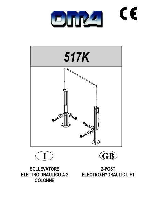
517K<br />
I<br />
SOLLEVATORE<br />
ELETTROIDRAULICO A 2<br />
COLONNE<br />
GB<br />
2-POST<br />
ELECTRO-HYDRAULIC LIFT
Manuale di istruzioni per l’uso e la manutenzione del<br />
SOLLEVATORE ELETTROIDRAULICO<br />
PER VEICOLI<br />
Modello 517K<br />
Instructions and maintenance manual for<br />
ELECTROHYDRAULIC LIFT<br />
FOR VEHICLES<br />
Model 517K<br />
Matricola N°<br />
Anno di costruzione<br />
Serial N°<br />
Year of manufacture<br />
COSTRUTTORE:<br />
MANUFACTURER:<br />
OMA S.p.A.<br />
Sede centrale: Via dell’Artigianato, 64<br />
36045 LONIGO (VI) - ITALY<br />
Telefono ++ / +444 / 436190<br />
Telefax ++ / +444 / 436208<br />
1° Emissione - 01/04/2005<br />
OMA S.p.A.<br />
Head office: Via dell’Artigianato, 64<br />
36045 LONIGO (VI) - ITALY<br />
Telefono ++ / +444 / 436190<br />
Telefax ++ / +444 / 436208<br />
1st Edition - 01/04/2005<br />
CENTRO DI ASSISTENZA AUTORIZZATO:<br />
AUTHORISED SERVICE CENTER:<br />
Rev.5 . . . . . . . . . . . . . . . . . . . . . . . . . . . . 04/04/2008<br />
1.
Indice<br />
Imballaggio, trasporto<br />
e stoccaggio Pag. 3<br />
Introduzione Pag. 4<br />
Cap.1<br />
Descrizione della<br />
macchina Pag. 6<br />
Cap.2 Specifiche tecniche Pag. 8<br />
Cap.3 Sicurezza Pag.13<br />
Cap.4 Installazione Pag.19<br />
Cap.5 Funzionamento ed uso Pag.29<br />
Cap.6 Manutenzione Pag.30<br />
Cap.7 Inconvenienti e rimedi Pag.33<br />
Appendice A<br />
Informazioni<br />
particolari<br />
Pag.34<br />
Appendice B Parti di ricambio Pag.34<br />
Contents<br />
Packing, transport and storage Page 3<br />
Introduction Page 4<br />
Chapter 1<br />
Chapter 2<br />
Description<br />
of the machine Page 6<br />
<strong>Tech</strong>nical<br />
specifications Page 8<br />
Chapter 3 Safety Page 13<br />
Chapter 4 Installation Page 19<br />
Chapter 5<br />
Operating principles<br />
and use Page 29<br />
Chapter 6 Maintenance Page 30<br />
Chapter 7 Troubleshooting Page 33<br />
Appendix A Special notes Page 34<br />
Appendix B Spare parts Page 34<br />
2.
IMBALLAGGIO, TRASPORTO E<br />
STOCCAGGIO<br />
LE OPERAZIONI DI IMBALLAGGIO, SOLLEVAMENTO, MOVI-<br />
MENTAZIONE, TRASPORTO E DISIMBALLO DEVONO ESSE-<br />
RE AFFIDATE ESCLUSIVAMENTE A PERSONALE CHE SIA<br />
ESPERTO IN TALI OPERAZIONI E CHE CONOSCA BENE IL<br />
SOLLEVATORE ED IL PRESENTE MANUALE<br />
IMBALLAGGIO<br />
Il sollevatore viene spedito smontato nei seguenti pezzi:<br />
Peso di un pezzo (Kg)<br />
1 Colonna lato comando completa Kg 260<br />
1 Colonna lato opposto completa Kg 200<br />
2 Bracci lunghi Kg 70<br />
2 Bracci corti Kg 60<br />
4 Salvapiedi Kg 2<br />
1 Assieme centralina Kg 30<br />
1 Pacco accessori Kg 10<br />
contenente:<br />
4 Kit bloccaggio braccio con spina<br />
Viterie<br />
PACKING, TRANSPORT AND<br />
STORAGE<br />
ALL PACKING, LIFTING, HANDLING, TRANSPORT AND<br />
UNPACKING OPERATIONS ARE TO BE PERFORMED EXCLU-<br />
SIVELY BY EXPERT PERSONNEL WITH KNOWLEDGE OF THE<br />
LIFT AND THE CONTENTS OF THIS MANUAL<br />
PACKING<br />
The lift is shipped disassembled into the following parts:<br />
Weight<br />
1 Complete command post 260 kg<br />
1 Other side complete post 200 kg<br />
2 Long arms 70 kg<br />
2 Short arms 60 kg<br />
4 Foot guard 2 kg<br />
1 Hydraulic power pack 30 kg<br />
1 Accessory package 10 kg<br />
that contain:<br />
4 Arm lock kit with pin<br />
Nuts and bolts<br />
Il sollevatore viene inviato in una gabbia di legno (Figura 1) del<br />
peso medio di circa 690 Kg.<br />
SOLLEVAMENTO E MOVIMENTAZIONE<br />
Le gabbie in legno possono essere sollevate e spostate sia con<br />
carrelli elevatori (fig.1) che con gru o carriponte (fig.2). Nel caso di<br />
movimentazione con gru o carriponte, le gabbie devono essere<br />
sempre imbracate con minimo 2 fasce.<br />
The lift is shipped in a wooden crate (Fig.1), weighing approx. 690<br />
kg.<br />
LIFTING AND HANDLING<br />
The wooden crates may be lifted and moved with a lift truck (Fig.1)<br />
crane or bridge crane (Fig.2).<br />
If either of the latter two are used, crates must be harnessed with<br />
at least 2 slings.<br />
Fig.1<br />
Fig.2<br />
3.
STOCCAGGIO<br />
Gli imballi devono sempre essere conservati in luoghi coperti e protetti<br />
a temperature comprese fra -10°C e +40°C. e non devono essere<br />
esposti ai raggi diretti del sole.<br />
IMPILAMENTO DEI PACCHI<br />
Il tipo di imballo previsto prevede la possibilità di impilare in magazzino<br />
fino ad 8 gabbie una sull’altra, purchè vengano correttamente<br />
disposte ed assicurate contro la caduta.<br />
Nei cassoni dei camion o nei containers si possono impilare fino a<br />
3 gabbie, purchè vengano reggiate bene ed assicurate contro<br />
la caduta.<br />
APERTURA DEGLI IMBALLI<br />
All’arrivo verificare che la macchina non abbia subito danni durante<br />
il trasporto e che ci siano tutti i pezzi indicati nella lista di spedizione.<br />
Le gabbie devono essere aperte adottando tutte le precauzioni per<br />
evitare danni alle e ai pezzi della macchina (evitare cadute di pezzi<br />
dalla gabbia durante l’apertura).<br />
ELIMINAZIONE DELL’IMBALLO<br />
Il legno della gabbia può essere riutilizzato o riciclato.<br />
STORAGE<br />
Packed machinery must always be kept in a covered, protected<br />
place, at a temperature between -10 °C e + 40°C, and must not be<br />
exposed to direct sunlight.<br />
CRATE STACKING.<br />
The type of packing allows the possibility of stacking up to 8 crates.<br />
Up to 3 crates may be stacked one upon the other on lorries or in<br />
containers if properly positioned and provided they are restrained<br />
to prevent falling.<br />
OPENING THE CRATES<br />
When the crates arrive, check that the machine has not been damaged<br />
during transport and that all parts listed are present.<br />
The crates must be opened using all possible precautionary measures<br />
to avoid damaging the machine or its parts. Make sure that<br />
parts do not fall from the crate during opening.<br />
DISPOSAL OF CRATES<br />
The wood of the crates may be re-used or recycled.<br />
INTRODUZIONE<br />
ATTENZIONE<br />
Questo manuale è stato scritto per il personale di officina addetto<br />
all’uso del sollevatore (operatore) e per il tecnico addetto<br />
alla manutenzione ordinaria (manutentore) pertanto, prima<br />
di effettuare qualsiasi operazione sul sollevatore e/o sul suo<br />
imballaggio, occorre leggere attentamente tutto il manuale,<br />
poichè esso contiene informazioni importanti per:<br />
LA SICUREZZA DELLE PERSONE addette all’uso ed alla<br />
manutenzione ordinaria,<br />
LA SICUREZZA DEL SOLLEVATORE,<br />
LA SICUREZZA DEI VEICOLI sollevati.<br />
CONSERVAZIONE DEL MANUALE<br />
Il manuale è parte integrante del sollevatore e deve sempre accompagnarlo,<br />
anche in caso di vendita.<br />
Esso deve sempre essere conservato in vicinanza del sollevatore,<br />
in luogo facilmente accessibile.<br />
L’operatore ed il manutentore devono poterlo reperire e consultare<br />
rapidamente in qualsiasi momento.<br />
SI RACCOMANDA, IN PARTICOLARE, UNA LETTURA ATTENTA<br />
E RIPETUTA DEL CAPITOLO 3, CHE CONTIENE IMPORTANTI<br />
INFORMAZIONI E AVVISI RELATIVI ALLA SICUREZZA.<br />
Il sollevatore è stato progettato e costruito rispettando quanto segue:<br />
LEGGI:<br />
Direttive europee: 98/37/CE-2004/108/CE-2006/95/CE<br />
NORME TECNICHE:<br />
Norme europee: EN 1493/ EN 292-1/ EN 292-2<br />
IMPIANTO ELETTRICO:<br />
UNI EN 60204, CEI 64/8<br />
INTRODUCTION<br />
WARNING<br />
This manual has been prepared for workshop personnel expert<br />
in the use of the lift (operator) and technicians responsible<br />
for routine maintenance (maintenance fitter); read the manual<br />
before carrying out any operation with the lift and/or the<br />
packing. This manual contains important information regarding:<br />
THE PERSONAL SAFETY of operators and maintenance<br />
workers,<br />
LIFT SAFETY,<br />
THE SAFETY OF LIFTED VEHICLES<br />
CONSERVING THE MANUAL<br />
The manual is an integral part of the lift , which it should always<br />
accompany , even if the unit is sold.<br />
The manual must be kept in the vicinity of the lift, in an easily accessible<br />
place.<br />
The operator and maintenance staff must be able to locate and<br />
consult the manual quickly and at any time.<br />
ATTENTIVE AND REPEATED READING OF CHAPTER 3 ,<br />
WHICH CONTAINS IMPORTANT INFORMATION AND SAFETY<br />
WARNINGS, IS PARTICULARLY RECOMMENDED.<br />
Lift rack has been designed and built in compliance with the following:<br />
LAWS:<br />
European directives: 98/37/CE-2004/108/CE-2006/95/CE<br />
TECHNICAL STANDARDS:<br />
European standards: EN 1493/ EN 292-1/ EN 292-2<br />
ELECTRICAL SYSTEM:<br />
UNI EN 60204, CEI 64/8<br />
4.
Il sollevamento, il trasporto, il disimballo, il montaggio, l’installazione<br />
e la messa in servizio, la taratura e le registrazioni iniziali, la<br />
manutenzione STRAORDINARIA, la riparazione, la revisione, lo<br />
spostamento e lo smantellamento del sollevatore devono essere<br />
eseguiti dai tecnici specializzati dei RIVENDITORI AUTORIZZATI<br />
o dei CENTRI ASSISTENZA AUTORIZZATI dal Costruttore (vedere<br />
centro assistenza autorizzato indicato nel frontespizio):<br />
Il costruttore non risponde di alcun danno a persone, veicoli<br />
od oggetti causati dagli interventi sopracitati se effettuati da<br />
personale non autorizzato o da un uso improprio o non consentito<br />
del sollevatore<br />
Per tutte queste attività vengono indicati, nel presente manuale,<br />
soltanto gli aspetti (operativi e di sicurezza) che possono essere<br />
utili anche all’operatore ed al manutentore per comprendere meglio<br />
la struttura ed il funzionamento del sollevatore e per un suo migliore<br />
utilizzo.<br />
Per comprendere il linguaggio adottato nel presente manuale, l’operatore<br />
deve possedere esperienza specifica nelle attività di officina,<br />
di assistenza, manutenzione e riparazione dei veicoli nonchè la<br />
capacità di interpretare correttamente i disegni e le descrizioni riportate<br />
nel manuale e la conoscenza delle norme antinfortunistiche<br />
generali e specifiche vigenti nel paese in cui viene installato il sollevatore.<br />
Gli stessi criteri valgono per la scelta del tecnico manutentore che<br />
dovrà, inoltre, possedere le conoscenze tecniche specifiche e specialistiche<br />
(meccaniche, elettriche) necessarie per effettuare in sicurezza<br />
gli interventi previsti nel manuale.<br />
Nel testo del manuale troverete spesso le diciture “operatore” e<br />
“manutentore” il cui significato è il seguente:<br />
OPERATORE: persona addetta all’uso del sollevatore.<br />
MANUTENTORE: persona addetta alla manutenzione ordinaria del<br />
sollevatore.<br />
The lifting, transport, unpacking, assembly, installation, starting up,<br />
initial adjustment and testing, EXTRAORDINARY maintenance, repair,<br />
overhauls, transport and dismantling of the lift must be performed<br />
by specialised personnel from the LICENSED DEALER or an<br />
SERVICE CENTRE authorised by the manufacturer (see authorised<br />
dealer on frontispiece).<br />
The manufacturer declines all responsibility for injury to persons<br />
or damage to vehicles or objects when any of the above<br />
mentioned operations has been performed by unauthorised<br />
personnel or when the rack has been subject to improper use.<br />
This manual indicates only the operative and safety aspects that<br />
may prove useful to the operator and maintenance worker, in better<br />
understanding the structure and operation of the lift and for<br />
best use of the same.<br />
In order to understand the terminology used in this manual, the<br />
operator must have specific experience in workshop, service,<br />
maintenance and repair activities, the ability to interpret correctly<br />
the drawings and descriptions contained in the manual and be acquainted<br />
with the general and specific safety rules relevant to the<br />
country in which the machine has been installed.<br />
The same applies to the maintenance fitter, who must also possess<br />
specific and specialised knowledge (mechanical, engineering)<br />
needed to perform the operations described in the manual in complete<br />
safety.<br />
The words “operator” and “maintenance fitter” used in this manual<br />
are construed as follows:<br />
OPERATOR: person authorised to use the lift<br />
MAINTENANCE FITTER: person authorised for routine maintenance<br />
of the lift.<br />
5.
CAP.1.<br />
DESCRIZIONE DELLA<br />
MACCHINA<br />
CHAPTER 1 DESCRIPTION OF THE<br />
MACHINE<br />
Il sollevatore elettroidraulico a 2 colonne è fisso, cioè ancorato al<br />
suolo ed è progettato e costruito per il sollevamento e lo stazionamento<br />
in quota di autoveicoli e furgoni.<br />
Il funzionamento è di tipo elettroidraulico.<br />
Il sollevatore è composto, principalmente da :<br />
gruppo struttura fissa ( colonne)<br />
gruppi mobili ( carrello + bracci )<br />
gruppi di sollevamento;<br />
quadro comando<br />
sicurezze.<br />
In figura 3 sono indicate le varie parti che compongono il sollevatore<br />
e le zone di lavoro consentite e riservate al personale addetto,<br />
attorno al sollevatore stesso.<br />
Lato comando: è il lato del sollevatore che comprende la zona riservata<br />
all’operatore in cui si accede al quadro comandi<br />
Lato servizio: è il lato opposto a quello comando.<br />
Lato anteriore: è il lato braccio lungo.<br />
Lato posteriore: è il lato braccio corto.<br />
The 2-post electro-hydraulic lift, is a fixed installation. This means<br />
that it is anchored to the ground and designed and built for lifting<br />
and positioning automobiles and vans at a certain height off the<br />
ground.<br />
The lift is driven by an electro-hydraulic operating system.<br />
The lift consists of the following main parts:<br />
fixed structure (posts);<br />
mobile units (carriage + arms);<br />
lift units;<br />
control box;<br />
safety devices.<br />
Figure 3 illustrates the various parts of the lift and the work areas<br />
reserved for use by operators around the lift.<br />
Command side: this side of the lift includes the area reserved for<br />
the operator to access the control box.<br />
Service side: this is the opposite side of the command side.<br />
Front side: the side with the long arm.<br />
Rear side: the side with the short arm.<br />
Lato posteriore<br />
Rear side<br />
Lato servizio<br />
Service side<br />
Lato comando<br />
Command side<br />
Lato anteriore<br />
Front side<br />
Fig.3<br />
GRUPPO STRUTTURA FISSA (Fig. 4)<br />
E’ costituito da :<br />
2 Colonne in lamiera di acciaio piegata alla cui base è saldata<br />
una piastra forata per il fissaggio al pavimento mediante tasselli.<br />
Alla colonna comando sono fissati il quadro elettrico di comando<br />
e la centralina idraulica.<br />
All’interno di ogni colonna si trovano i gruppi mobili di sollevamento<br />
dell’automezzo.<br />
FIXED STRUCTURE (Fig. 4)<br />
This structure consists of:<br />
2 Posts built with bent steel plate. The base is welded to a drilled<br />
plate to be fixed to the floor with screw anchors.<br />
The electric control box and the hydraulic power unit are attached<br />
to the command post.<br />
The vehicle mobile lifting units are located inside each post.<br />
Fig.4<br />
Gruppi struttura fissa<br />
Fig.4<br />
Fixed structure units<br />
6.
GRUPPI DI SOLLEVAMENTO (Fig. 5)<br />
Ciascuno è costituito da :<br />
un carrello (1) in lamiera di acciaio saldata, collegato nella parte<br />
inferiore, mediante flange e perni, ai bracci di sollevamento.<br />
Al centro, il carrello è collegato ad una catena (2) che riceve il<br />
movimento dal cilindro idraulico (6) e permette il sollevamento.<br />
I carrelli sono dotati di rulli di scorrimento e pattini di guida.<br />
Due bracci telescopici di cui uno lungo (3) e uno corto (4), costruiti<br />
in tubolare di acciaio e recanti ad una estremità il piattello<br />
(5) regolabile in altezza per la presa della macchina e dalla parte<br />
opposta il foro di collegamento con il carrello<br />
LIFT UNITS (Fig. 5)<br />
Each unit consists of:<br />
one carriage (1) built with welded steel plate, connected at the<br />
bottom to the lift arms by means of flanges and pins. In the<br />
middle, the carriage is connected to a chain (2) that receives the<br />
movement from the hydraulic cylinder (6) and performs the lifting<br />
operation. The carriages are equipped with sliding rollers and<br />
guide runners.<br />
Two telescopic arms, one long (3) and one short (4), built with<br />
tubular steel with a pad (5) at each end that can be height adjusted<br />
to hold the car and on the opposite side the carriage connection<br />
hole.<br />
2 1<br />
1<br />
3 5 4<br />
6<br />
Fig.5<br />
Gruppo di sollevamento<br />
Fig.5<br />
Lift unit<br />
GRUPPO DI TRASMISSIONE (Fig.5)<br />
La trasmissione viene fornita dalla centralina idraulica che invia olio<br />
sotto pressione al cilindro (6). I volumi dei cilindri sono<br />
proporzionati in modo da sincronizzare il movimento dei carrelli<br />
QUADRO DI COMANDO ( Fig.6)<br />
Sul pannello del quadro elettrico di comando sono installati :<br />
L’interrutore generale (11) - Il pulsante di salita (12) - Il pulsante di<br />
stazionamento (13) - Il pulsante di discesa (14)<br />
TRANSMISSION UNIT (Fig.5)<br />
Transmission is supplied by the hydraulic power unit that sends oil<br />
under pressure to the cylinder (6). The cylinder volumes are<br />
proportioned to synchronize the carriage movement.<br />
CONTROL BOX (Fig.6)<br />
The panel that houses the electric control box contains the following:<br />
Main switch (11) - Up push button (12) - Parking push button (13) -<br />
Down push button (14)<br />
Fig.7 Centralina idraulica<br />
11<br />
12<br />
15<br />
18<br />
16<br />
13<br />
17<br />
20<br />
14<br />
19<br />
Fig.6<br />
Fig.6<br />
Quadro di comando<br />
Control box<br />
CENTRALINA IDRAULICA (Fig.7)<br />
La centralina idraulica è composta da un motore elettrico (15), una<br />
pompa idraulica ad ingranaggi (16), un’elettrovalvola di discesa<br />
(17) dotata di un dispositivo di scarico manuale dell’olio (vedi cap.<br />
Uso e Manutenzione), una valvola di massima pressione (18), un<br />
serbatoio olio (19), il tubo di mandata e recupero (20) olio<br />
N.B.: il tubo di mandata olio può trovarsi in pressione.<br />
Fig.7<br />
Hydraulic power unit<br />
HYDRAULIC POWER UNIT (Fig.7)<br />
The hydraulic power unit consists of an electric motor (15), a geared<br />
hydraulic pump (16), down electro-valve (17) equipped with a<br />
manual oil drain valve (see the Use and Maintenance chapter), a<br />
maximum pressure valve (18), oil reservoir (19) as well as an oil<br />
delivery and return pipe (20).<br />
Note: The oil delivery pipe may be under pressure.<br />
7.
SICUREZZE<br />
Le sicurezze sono costituite da :<br />
Un sistema di bloccaggio bracci che non permettono movimenti<br />
involontari dei bracci del ponte.<br />
4 salvapiedi sui bracci che evitano lo schiacciamento dei piedi in<br />
fase di discesa.<br />
Un microinterruttore che interviene in caso di cattivo livellamento<br />
dei carrelli.<br />
I martelletti di sicurezza sui carrelli che intervengono in fase di<br />
stazionamento del carico in quota ed in caso di rottura della<br />
catena.<br />
Un finecorsa di estremità colonna che non permette extracorsa<br />
del cilindro e dei carrelli.<br />
Una valvola di blocco in caso di rottura del sistema idraulico.<br />
Le sicurezze elettriche generiche.<br />
Queste sicurezze saranno sviluppate in maggior dettaglio nei seguenti<br />
capitoli.<br />
SAFETY DEVICES<br />
The safety devices include:<br />
Arm locking system that prevents accidental movements of the<br />
rack arms.<br />
4 foot guards on the arms that prevent feet from being smashed<br />
while the vehicle is descending;<br />
Microswitch that trips when the carriages are unleveled.<br />
Safety wedges on the carriages which are activated when the<br />
load is positioned at a certain height off the ground and if the<br />
chain breaks.<br />
A post end limit switch that does not allow the cylinder and the<br />
carriages to exceed their travel limits.<br />
Lock valve that trips if the hydraulic system ruptures.<br />
General electric safety devices.<br />
These safety devices will be described in further detail in the following<br />
chapters.<br />
CAP.2<br />
SPECIFICHE TECNICHE<br />
CHAPTER. 2 TECHNICAL<br />
SPECIFICATIONS<br />
PORTATA: ................................................3000 Kg (29430 N)<br />
Alt. max. sollevamento auto ......................2100 mm<br />
Alt. min. supporti sollevamento ................. 95 mm<br />
Larg. libera tra colonne .............................2645 mm<br />
Larg. totale ................................................3345 mm<br />
Lung. massima braccio lungo....................1240 mm<br />
Lung. minima............................................. 755 mm<br />
Lung. massima braccio corto .................... 945 mm<br />
Lung. minima............................................. 630 mm<br />
Tempo di salita.......................................... 30 sec<br />
Tempo di discesa ...................................... 30 sec.<br />
Peso totale del sollevatore ........................circa 630 Kg<br />
Rumorosità................................................ 70dB(A)/1m<br />
Temperatura di funzionamento : ...............-10°C / +50°C<br />
Pressione di lavoro....................................185 bar<br />
Ambiente di lavoro: locale chiuso.<br />
CAPACITY: ...............................................3000 Kg (29430 N)<br />
Car max. lifting height................................2100 mm<br />
Lift min. stand height ................................. 95 mm<br />
Clearance between posts..........................2645 mm<br />
Total width.................................................3345 mm<br />
Long arm maximum length........................1240 mm<br />
Minimum length......................................... 755 mm<br />
Short arm maximum length ....................... 945 mm<br />
Minimum length......................................... 630 mm<br />
Rise time ................................................... 30 sec.<br />
Descent time ............................................. 30 sec.<br />
Total lift weight ..........................................about 630 Kg<br />
Noise ......................................................... 70dB(A)/1m<br />
Operating temperature: .............................-10°C/+50°C<br />
Working pressure ......................................185 bar<br />
Work environment: closed room.<br />
Fig.8<br />
Dimensioni ed ingombri<br />
Fig.8<br />
Dimensions and overall clearances<br />
8.
MOTORE ELETTRICO:<br />
Potenza del motore<br />
elettrico<br />
Trifase<br />
2,2 KW 2,2 KW<br />
Monofase<br />
Tensione 230-400V trif.+/- 5% 230V mono +/- 5%<br />
Frequenza 50 Hz 50 Hz<br />
Assorbimento<br />
N° poli 4<br />
230V:10,7A<br />
400V:6,2A<br />
15,9A<br />
Velocità 1400 Giri / 1’ 1380 Giri / 1’<br />
Forma costruttiva<br />
B14<br />
Classe di isolamento F IP54<br />
Tipo C90 M90 LB4<br />
Il collegamento del motore deve essere eseguito riferendosi agli<br />
schemi elettrici allegati.<br />
Il senso di rotazione del motore è sinistro (antiorario) come indicato<br />
nella targhetta applicata al motore stesso.<br />
POMPA<br />
Tipo ...........................................................18<br />
Modello......................................................10A5X348N<br />
Cilindrata ...................................................5 cm3/g<br />
Taratura valvola di massima .....................200 bar<br />
ELECTRIC MOTOR<br />
Electric motor power rating<br />
Three-phase<br />
2,2 KW 2,2 KW<br />
Singlephase<br />
Voltage 230-400V 3ph.+/-5% 230V 1ph. +/- 5%<br />
Frequency 50 Hz 50 Hz<br />
Absorption<br />
No. of poles 4<br />
230V:10,7A<br />
400V:6,2A<br />
15,9A<br />
Speed 1400 RPM 1380 RPM<br />
Construction size<br />
B14<br />
Insulation class F IP54<br />
Type C90 M90 LB4<br />
The motor must be connected with reference to the attached wiring<br />
diagrams.<br />
The motor rotates to the left (counterclockwise) as indicated on the<br />
data plate attached to the motor.<br />
PUMP<br />
Type ..........................................................18<br />
Model.........................................................10A5X348N<br />
Size ...........................................................5 cm3/g<br />
Relief valve set-up.....................................200 bar<br />
OLIO<br />
Il serbatoio dell’olio contiene olio idraulico minerale secondo la normativa<br />
ISO/DIN 6743/4 con grado di contaminazione non superiore<br />
alla classe 18/15 secondo la normativa ISO 4406 esempio olio IP<br />
HYDRUS OIL 32; SHELL TELLUS OIL T32 o equivalenti.<br />
SCHEMA OLEODINAMICO<br />
12<br />
P2<br />
10 10<br />
12<br />
P1<br />
OIL<br />
The oil reservoir contains hydraulic mineral oil in accordance with<br />
ISO/DIN 6743/4 with a level of contamination that does not exceed<br />
class 18/15 according to ISO 4406, for example IP HYDRUS OIL<br />
32; SHELL TELLUS OIL T32 or equivalent.<br />
HYDRAULIC OIL DIAGRAM<br />
Rif.<br />
Descrizione<br />
P1<br />
Cilindro L.C.<br />
P2<br />
Cilindro L.O.<br />
3 Valvola reg. flusso<br />
4 Elettrovalvola di scarico<br />
5 Valvola di non ritorno<br />
6 Valvola di massima<br />
7 Pompa<br />
8 Motore<br />
9 Filtro<br />
10 Valvola di blocco<br />
11 Serbatoio<br />
12 Valvola di liv. a fine corsa<br />
8<br />
3 4<br />
5<br />
6<br />
7<br />
9<br />
11<br />
Ref.<br />
Description<br />
P1<br />
Cylinder C.S.<br />
P2<br />
Cylinder O.S.<br />
3 Flow control valve<br />
4 Drain electro-valve<br />
5 Check valve<br />
6 Maximum valve<br />
7 Pump<br />
8 Motor<br />
9 Filter<br />
10 Lock valve<br />
11 Reservoir<br />
12 End of stroke leveling valve<br />
9.
SCHEMI ELETTRICI<br />
Schema elettrico trifase<br />
WIRING DIAGRAM<br />
Three phase wiring diagram<br />
Rif.<br />
Ref.<br />
Descrizione<br />
Description<br />
Marca<br />
Brand<br />
Articolo<br />
Article<br />
C1-C2 Elettromagnete Electromagnet WARNER EL. TT6-1 24V 50Hz 1<br />
C3 Elettrovalvola Electro-valve OIL SISTEM 24VAC 50/60Hz ED100% 1<br />
FU1-UF2 Portafusibili Fuse carrier WEBER PCH10x38 + CH10x38 3<br />
PTC Limitatore di temperatura Temperature limiter 1<br />
QM1 Microinterruttore sensore fune Cable sensor microswitch PIZZATO FR1454 1<br />
QM5 Fine corsa salita Ascent limit switch PIZZATO FR654 1<br />
QS Interruttore generale Master switch SPRECHER LA16-1753 + LFS2-N-6-175 1<br />
KM1 Teleruttore Contactor 24V 50/60Hz 1<br />
M Motore elettrico Electric motor 230V/400V 50Hz 1<br />
SB1 Pulsante salita Up push buttons 1 NO 1<br />
SB2 Pulsante discesa Down push button 2 NO 1<br />
SB3 Pulsante stazionamento Parking push button 1 NO 1<br />
SB6 Pulsante esclusione finecorsa Limit switch excl. button 2 NO 1<br />
TM Trasformatore Transformer C.E. 230-400/24V 75VA 50/60Hz 1<br />
Morsetti linea Line terminals CABUR CBD2 2.5 mmq 3<br />
Morsetti terra PE terminals CABUR TE4/D-TE4/0 4mmq 1<br />
Q.tà<br />
Q.ty<br />
10.
SCHEMI ELETTRICI<br />
Schema elettrico monofase<br />
WIRING DIAGRAM<br />
Single phase wiring diagram<br />
Rif.<br />
Ref.<br />
Descrizione<br />
Description<br />
Marca<br />
Brand<br />
Articolo<br />
Article<br />
C1-C2 Elettromagnete Electromagnet WARNER EL. TT6-1 24V 50Hz 1<br />
C3 Elettrovalvola Electro-valve OIL SISTEM 24VAC 50/60Hz ED100% 1<br />
FU1-UF2 Portafusibili Fuse carrier WEBER PCH10x38 + CH10x38 3<br />
QM1 Microinterruttore sensore fune Cable sensor microswitch PIZZATO FR1454 1<br />
QM5 Fine corsa salita Ascent limit switch PIZZATO FR654 1<br />
QS Interruttore generale Master switch SPRECHER LA16-1753 + LFS2-N-6-175 1<br />
KM1 Teleruttore Contactor 24V 50/60Hz 1<br />
M Motore elettrico Electric motor 230V 50Hz 1<br />
SB1 Pulsante salita Up push buttons 1 NO 1<br />
SB2 Pulsante discesa Down push button 2 NO 1<br />
SB3 Pulsante stazionamento Parking push button 1 NO 1<br />
SB6 Pulsante esclusione finecorsa Limit switch excl. button 2 NO 1<br />
TM Trasformatore Transformer C.E. 230/24V 75VA 50/60Hz 1<br />
Morsetti linea Line terminals CABUR CBD2 2.5 mmq 2<br />
Morsetti terra PE terminals CABUR TE4/D-TE4/0 4mmq 1<br />
Q.tà<br />
Q.ty<br />
11.
TIPI DI VEICOLI SOLLEVABILI E INGOMBRI<br />
Il sollevatore si adatta praticamente a tutti i veicoli di peso non superiore<br />
a 3000 Kg e le cui dimensioni non eccedano quelle riportate<br />
di seguito.<br />
DIMENSIONI MASSIME DEI VEICOLI DA SOLLEVARE<br />
La larghezza non deve eccedere i 2200 mm.<br />
Il passo tra gli assi non deve eccedere i 3000 mm.<br />
L’altezza minima da terra può interferire con le strutture del<br />
sollevatore. Fare attenzione soprattutto alle autovetture sportive.<br />
Eventuali carrozzati speciali possono essere sollevati tenendo però<br />
conto della portata del sollevatore.<br />
Anche la zona di rischio per le persone dovrà essere adeguata<br />
alle dimensioni speciali del veicolo.<br />
Gli schemi seguenti riportano i criteri per definire i limiti di impiego<br />
del sollevatore.<br />
VEHICLE WEIGHT AND SIZE<br />
Lift rack can be adapted to virtually all vehicles no heavier than<br />
3000 kg, the dimensions of which do not exceed the following.<br />
MAXIMUM DIMENSIONS OF VEHICLES TO BE LIFTED<br />
Max. width: 2200 mm.<br />
Max. wheelbase: 3000 mm.<br />
The underbody of cars with low ground clearance may interfere<br />
with the structure of the lift. Pay particular attention in the<br />
case of low body sports cars.<br />
Always keep the capacity of the lift in mind in the case of vehicles<br />
with particular characteristics.<br />
The danger zone will be determined by the dimensions of the<br />
vehicle.<br />
The diagrams below include the criteria for defining the limits of<br />
use of the car rack.<br />
C<br />
B<br />
A<br />
Min.(mm)<br />
A - 2200<br />
B - 3000<br />
C 150 -<br />
Max.(mm)<br />
Fig.12<br />
Misure minime e massime<br />
PER INGOMBRI MAGGIORI VERIFICARE IL CARICO MASSIMO<br />
E LO SBILANCIAMENTO DEL CARICO.<br />
Fig.12<br />
Minimum and maximum dimensions<br />
CHECK MAXIMUM LOAD CAPACITY AND LOAD DISTRIBU-<br />
TION IN THE CASE OF LARGER VEHICLES.<br />
PESI MASSIMI DEI VEICOLI DA SOLLEVARE<br />
MAXIMUM WEIGHT OF THE VEHICLE TO BE LIFT<br />
1800 1200 1200<br />
1800<br />
MAX.3000 Kg.!<br />
Fig.13<br />
Distribuzione dei pesi<br />
Fig.13<br />
Weight distribution<br />
12.
CAP.3<br />
SICUREZZA<br />
CHAPTER 3<br />
SAFETY<br />
É estremamente importante leggere questo capitolo attentamente<br />
ed in ogni sua parte poichè contiene importanti informazioni<br />
sui rischi che operatore e manutentore possono correre<br />
in caso di un uso errato del ponte sollevatore.<br />
Nel testo che segue troverete chiare spiegazioni su alcune situazioni<br />
di rischio o pericolo che si possono verificare durante<br />
l’uso e la manutenzione del sollevatore, sui dispositivi di sicurezza<br />
adottati e sul loro uso corretto, sui rischi residui e sui<br />
comportamenti da tenere (precauzioni generali e specifiche<br />
per eliminarli o neutralizzarli).<br />
ATTENZIONE:<br />
Il sollevatore è stato progettato e costruito per il<br />
sollevamento e lo stazionamento in quota dei veicoli<br />
in ambiente chiuso. Ogni altro uso non è consentito<br />
ed in particolare esso non è idoneo per<br />
operazioni di:<br />
- lavaggio e verniciatura;<br />
- ponteggio o sollevamento di persone;<br />
- pressa per schiacciare;<br />
- montacarichi;<br />
- CRIC per sollevare o cambiare ruote.<br />
Il costruttore non risponde di alcun danno a persone,<br />
veicoli od oggetti causati dall’uso improprio<br />
o non consentito dei sollevatori.<br />
É estremamente importante che in fase di salita o discesa l’operatore<br />
agisca soltanto dalla postazione di comando indicata in fig.14.<br />
É vietato a chiunque sostare entro la zona di rischio indicata in<br />
fig.14.<br />
In fase di lavoro la presenza di persone sotto il veicolo è ammessa<br />
soltanto quando il veicolo è già sollevato.<br />
ATTENZIONE:<br />
LA PRESENZA DI PERSONE SOTTO IL VEICOLO<br />
SOLLEVATO E’ AMMESSA SOLTANTO QUANDO<br />
IL SOLLEVATORE E’ IN STAZIONAMENTO SUI<br />
MARTELLETTI DI SICUREZZA.<br />
NON UTILIZZARE LA MACCHINA SENZA LE<br />
PROTEZIONI O CON LE PROTEZIONI<br />
DISATTIVATE.<br />
IL MANCATO RISPETTO DI QUESTE NORME<br />
PUO’ RECARE<br />
GRAVI DANNI<br />
ALLE PERSONE,<br />
AL SOLLEVATO-<br />
RE ED AI VEICO-<br />
LI SOLLEVATI.<br />
Zona di rischio<br />
Danger zone<br />
It is vital to read this chapter of the manual carefully and from<br />
beginning to end as it contains important information regarding<br />
the risks that the operator or maintenance fitter may be<br />
exposed to in the eventuality that the lift is used incorrectly.<br />
The following text contains clear explanations regarding certain<br />
situations of risk or danger that may arise during the operation<br />
or maintenance of the lift, the safety devices installed<br />
and the correct use of such systems, residual risks and operative<br />
procedures to use (general and specific precautions to<br />
eliminate potential hazards).<br />
WARNING:<br />
Lift is designed and built to lift vehicles and hold<br />
them in the elevated position in a closed workshop.<br />
All other uses are unauthorised. In particular,<br />
the lift is not suitable for:<br />
- washing and respray work;<br />
- creating raised platforms or lifting personnel;<br />
- use as a makeshift press for crushing purposes;<br />
- use as goods lift;<br />
- use as a jack for lifting vehicles or changing<br />
wheels.<br />
The manufacturer disclaims all liability for injury<br />
to persons or damage to vehicles and other property<br />
caused by the incorrect and unauthorised<br />
use of the lift.<br />
During lift and descent movements, the operator must remain in<br />
the command station as defined in figure 14. The presence of persons<br />
inside the danger zone indicated in the same figure is strictly<br />
prohibited. The presence of persons beneath the vehicle during<br />
operations is permitted only when the vehicle is parked in the elevated<br />
position.<br />
DO NOT USE THE LIFT WITHOUT PROTECTION<br />
DEVICES OR WITH THE PROTECTION DEVICES<br />
INHIBITED.<br />
FAILURE TO COMPLY WITH THESE REGULA-<br />
TIONS CAN CAUSE SERIOUS INJURY TO PER-<br />
SONS, AND IRREPERABLE DAMAGE TO THE<br />
LIFT AND THE VEHICLE BEING LIFTED.<br />
WARNING:<br />
THE PRESENCE OF PERSONS BENEATH THE<br />
VEHICLE IS PERMITTED ONLY WHEN THE LIFT<br />
IS IN THE<br />
PARKING<br />
POSITION ON<br />
THE SAFETY<br />
WEDGES.<br />
Fig.14<br />
Zone di lavoro<br />
Zona operatore<br />
Operator zone<br />
Fig.14<br />
Workings area<br />
13.
PRECAUZIONI GENERALI<br />
L’operatore ed il manutentore sono tenuti al rispetto delle prescrizioni<br />
contenute in leggi e norme antinfortunistiche vigenti nel paese<br />
in cui è installato il sollevatore.<br />
Devono inoltre:<br />
operare sempre dalle postazioni di lavoro previste ed indicate<br />
nel manuale;<br />
non rimuovere nè disattivare i carter e le protezioni meccaniche,<br />
elettriche, o di altra natura;<br />
prestare attenzione agli avvisi di sicurezza riportati nelle targhette<br />
applicate sulla macchina e nel manuale.<br />
Nel testo del manuale gli avvisi di sicurezza saranno evidenziati<br />
nelle forme seguenti:<br />
PERICOLO: Indica un pericolo imminente che può causare danno<br />
alle persone (gravi lesioni o anche la morte).<br />
ATTENZIONE: Indica situazioni e/o comportamenti rischiosi che<br />
possono causare danni alle persone (lesioni più o meno gravi e/o<br />
anche la morte).<br />
CAUTELA: Indica situazioni e/o comportamenti rischiosi che possono<br />
causare danni di minore gravità alle persone e/o danni al sollevatore,<br />
al veicolo o ad altre cose.<br />
RISCHIO DI FOLGORAZIONE: è un particolare avviso di sicurezza<br />
che viene riportato sul sollevatore, tramite targhetta, in alcuni<br />
punti dove è particolarmente elevato il rischio di forti scosse elettriche.<br />
RISCHI E PROTEZIONI<br />
Vediamo ora quali rischi possono correre gli operatori o il manutentore<br />
nelle fasi d’uso del sollevatore e quali protezioni sono state<br />
adottate dal costruttore per ridurre al minimo tali rischi:<br />
SPOSTAMENTI LONGITUDINALI E LATERALI<br />
Gli spostamenti longitudinali sono i movimenti in avanti o all’indietro<br />
del carico.<br />
Gli spostamenti laterali sono i movimenti verso destra o verso sinistra<br />
che il veicolo può avere, specialmente durante la fase di salita<br />
sul sollevatore.<br />
Essi sono evitabili posizionando in maniera corretta i piattelli dei<br />
bracci appoggiandoli nei punti di presa consentiti della vettura e regolando<br />
alla stessa altezza (avvitando o svitando) i piattelli stessi.<br />
Lo spostamento dell’automezzo sui bracci, la regolazione dei<br />
bracci e dei piattelli deve essere fatto esclusivamente a bracci<br />
totalmente abbassati cioè con i piattelli liberi da qualunque<br />
contatto con il mezzo.<br />
GENERAL PRECAUTIONS<br />
The operator and the maintenance fitter are required to observe<br />
the prescriptions of accident prevention legislation in force in the<br />
country of installation of the lift.<br />
Furthermore, the operator and maintenance fitter must:<br />
Always work in the scheduled working area as shown in the<br />
manual.<br />
never remove or deactivate the guards and mechanical, electrical,<br />
or other types of safety devices;<br />
read the safety notices affixed to the machine and the safety information<br />
in this manual.<br />
In the manual all safety notices are shown as follows:<br />
DANGER: Indicates imminent danger that can result in serious injury<br />
or death.<br />
WARNING: Indicates situations and/or types of manoeuvres that<br />
are unsafe and can cause injuries of various degrees or death.<br />
CAUTION: Indicates situations and/or types of manoeuvres that<br />
are unsafe and can cause minor injury to persons and/or damage<br />
the lift, the vehicle or other property.<br />
RISK OF ELECTRIC SHOCK: specific safety notice affixed to the<br />
lift in areas where the risk of electric shock is particularly high.<br />
RISKS AND PROTECION DEVICES<br />
We shall now examine the risks to which operators or maintenance<br />
fitters may be exposed when the vehicle is immobilised in the raised<br />
position, together with the protection devices adopted by the<br />
manufacturer to reduce all such hazards to the minimum:<br />
LONGITUDINAL AND LATERAL MOVEMENT<br />
Longitudinal movement is considered the backward and forward<br />
shifting of the load.<br />
Lateral movement implies the shifting to the left or right of the<br />
vehicle, especially during the lifting phase on the rack.<br />
These movements can be avoided by positioning the vehicle correctly<br />
on the arm disk support plates, which must be previously<br />
adjusted to the same height (by loosening or tightening) as the<br />
vehicle.<br />
Do not move the vehicle in relation to the arms or adjust arms<br />
and disk support plates until the arms have been totally lowered,<br />
i.e. the disk support plates must be free from all contact<br />
with the vehicle.<br />
Fig.15<br />
Rischio di caduta del veicolo<br />
Fig.15<br />
Risk of vehicle fall<br />
ATTENZIONE<br />
NON TENTARE DI SPOSTARE IL MEZZO QUANDO I PIATTELLI<br />
DI APPOGGIO SONO GIÀ A CONTATTO CON QUESTO.<br />
WARNING<br />
DO NOT ATTEMPT TO MOVE THE VEHICLE WHEN IT IS RE-<br />
STING ON THE DISK SUPPORT PLATES.<br />
14.
É estremamente importante posizionare il mezzo sul sollevatore in<br />
modo da avere una corretta ripartizione dei pesi sui bracci (fig.16)<br />
Per la sicurezza delle persone e dei mezzi è importante che:<br />
si rispetti la zona di rischio durante il sollevamento (fig.14)<br />
il motore sia spento,la marcia innestata ed il freno a mano tirato.<br />
il veicolo sia posizionato<br />
in maniera corretta<br />
(fig.16)<br />
vengano sollevati soltanto<br />
i veicoli ammessi<br />
(fig.12-13) senza superare<br />
portata ed ingombri<br />
previsti.<br />
Fig.16<br />
Veicolo caricato correttamente<br />
It is very important to position the vehicle on the lift so that the<br />
weight is correctly distributed on the arms (fig.16).<br />
To ensure the safety of persons and equipment, it is important that:<br />
people rest outside the danger zone while the vehicle raising<br />
(fig.14)<br />
the engine is off, the<br />
clutch engaged and the<br />
parking brake<br />
pulled.<br />
that vehicle is correctly<br />
positioned (fig.16)<br />
only authorised vehicles<br />
(fig.12-13) are raised without<br />
exceeding the rated<br />
capacity and overall dimensions.<br />
Fig.16<br />
Correctly loaded vehicle<br />
RISCHI IN FASE DI SOLLEVAMENTO DEL VEICOLO<br />
Contro i sovraccarichi in peso e contro eventuali rotture sono stati<br />
adottati i seguenti dispositivi di sicurezza:<br />
in caso di sovraccarico sul motore interviene il relè termico nel<br />
quadro elettrico.<br />
in caso di sovraccarico del sollevatore interviene la valvola di<br />
massima pressione (fig.17) posta sulla centralina oleodinamica.<br />
in caso di rottura del sistema idraulico (centralina/tubi) interviene<br />
la valvola di blocco posta sul cilindro<br />
in caso di extra corsa della parte mobile è stato previsto un finecorsa<br />
elettrico nella parte superiore della colonna comando; in<br />
caso di mancato funzionamento del finecorsa, dopo circa 30 millimetri<br />
di ulteriore salita il cilindro arriva a fine corsa quindi interviene<br />
la valvola di massima pressione sulla centralina.<br />
in caso di rottura del cilindro idraulico intervengono automaticamente<br />
i martelletti di sicurezza (rif.1) (vedere Fig.17a), posti all’<br />
interno delle colonne (2), che, spinti dalla molla (3), arrestano<br />
immediatamente i carrelli (4) impedendone la discesa.<br />
RISKS WHILE THE VEHICLE IS BEING RAISED<br />
The following safety devices have been installed to protect against<br />
overweight conditions and equipment failure:<br />
the thermal relay in the electric box will trip if the motor is overloaded.<br />
the maximum pressure valve (fig.17), located on the hydraulic oil<br />
power unit, will trip if the lift is overloaded.<br />
the block valve, located on the cylinder, will trip if the hydraulic<br />
system ruptures (power unit/hoses)<br />
if the mobile part exceeds its rated travel distance, an electric limit<br />
switch in the top of the command post will trip. If the limit<br />
switch fails, after rising about 30 millimetres, the cylinder reaches<br />
the limit and then the maximum pressure valve on the<br />
power unit trips.<br />
If the hydraulic cylinder breaks, the safety wedges will trip (ref.1,<br />
see.fig.17a), located inside the posts (2). The wedges are pushed<br />
by the spring (3) and immediately stop the carriages (4)<br />
preventing their descent<br />
4<br />
1<br />
2<br />
3<br />
Fig.17<br />
1 Valvola di ritegno Check valve<br />
2 Elettrovalvola Solenoid valve<br />
3 Scarico manuale Manual outlet<br />
4 Carico olio Delivery<br />
5 Tubo per recupero olio Drain hose<br />
6 Valvola regolatrice di scarico Outlet adjusting valve<br />
7 Valvola massima pressione Relief valve<br />
CARRELLO IN FASE DI DISCESA<br />
DESCENDING CARRIAGE<br />
CARRELLO IN FASE ARRESTO<br />
O SALITA<br />
STOPPING OR RISING<br />
CARRIAGE<br />
Fig.17a<br />
15.
RISCHI DIRETTI ALLE PERSONE<br />
In questo paragrafo verranno illustrati i rischi che operatore, manutentore<br />
e chi si trova nell’area di lavoro del sollevatore, possono<br />
correre a causa di un uso non corretto del sollevatore stesso.<br />
RISKS TO PERSONS<br />
This paragraph illustrates risks to which the operator, maintenance<br />
worker or any person near the operating area of the lift may be exposed<br />
in the case of improper use of equipment.<br />
RISCHIO DI SCHIACCIAMENTO<br />
DELL’OPERATORE<br />
dovuto ad una errata posizione dell’operatore<br />
addetto al quadro comandi.<br />
Durante la fase di discesa delle pedane<br />
e del veicolo l’operatore non deve<br />
mai portarsi sotto le parti mobili in fase<br />
di discesa ma operare soltanto dalla<br />
zona comando (fig.18).<br />
Fig.18<br />
Rischio di schiacciamento dell’operatore<br />
RISK OF CRUSHING<br />
(OPERATOR)<br />
Possible if the operator controlling<br />
the lift is not in the specified position<br />
at the command panel. When the<br />
platforms and vehicle are descending,<br />
the operator must never be<br />
partly or completely underneath the<br />
moving structure. During this phase<br />
the operator must remain in the<br />
command zone (fig.18).<br />
Fig.18<br />
Operator crushing risk<br />
RISCHIO DI SCHIACCIAMENTO DEL PERSONALE IN GENERE<br />
Durante la fase di discesa del sollevatore<br />
e del veicolo il personale non<br />
deve sostare in zone interessate<br />
dalle traiettorie di discesa (fig.19).<br />
L’operatore deve manovrare solo<br />
dopo essersi accertato che nessuna<br />
persona sia in posizioni pericolose.<br />
RISK OF CRUSHING (PERSONNEL)<br />
When the platforms and vehicle are descending<br />
personnel are prohibited from<br />
entering the area beneath the moving<br />
parts of the lift (fig.19). The lift operator<br />
must not start the manoeuvre until it<br />
has been clearly established that there<br />
are no persons in potentially dangerous<br />
positions.<br />
Fig.19<br />
Rischio di schiacciamento del<br />
personale in genere<br />
Fig.19<br />
Generic people crushing risk<br />
RISCHIO DI URTO<br />
Dovuto alle parti del sollevatore o<br />
del veicolo posizionate ad altezza<br />
d’uomo.<br />
Quando, per ragioni di lavoro, il sollevatore<br />
viene fermato a quote relativamente<br />
basse (inferiori a 1,75 m<br />
dal suolo) vi è il rischio di urtare<br />
contro le parti non evidenziate da<br />
particolari colorazioni (Fig.20).<br />
RISK OF IMPACT<br />
Caused by parts of the lift or the vehicle<br />
that are positioned at head height.<br />
When, due to operational reasons, the<br />
lift is immobilised at relatively low elevations<br />
(less than 1.75 m from the<br />
ground) personnel must be careful to<br />
avoid impact with parts of the machine<br />
not marked with special hazard colouring<br />
(Fig.20).<br />
Fig.20<br />
Rischio di urto<br />
Fig.20 Impact risk<br />
RISCHIO DI SPOSTAMENTO DEL<br />
VEICOLO<br />
Dovuto ad operazioni da compiere e<br />
che generano spinte sul veicolo<br />
(fig.21).<br />
Se il veicolo é di dimensioni o pesi<br />
ragguardevoli uno spostamento può<br />
rappresentare una situazione di sovraccarico<br />
o sbilanciamento non<br />
previsto pertanto evitare in maniera<br />
assoluta tali manovre.<br />
RISKS DUE TO VEHICLE<br />
MOVEMENT<br />
Movement may be caused during operations<br />
which involve force sufficient to<br />
move the vehicle (Fig.21).<br />
If the vehicle is of considerable dimensions<br />
or weight, movement may lead<br />
to overloading or unbalancing; all<br />
measures must be taken to avoid such<br />
an occurrence.<br />
Fig.21<br />
Rischio di spostamento del veicolo<br />
Fig.21<br />
Vehicle movement risk<br />
16.
RISCHIO DI CADUTA DEL<br />
VEICOLO DAL SOLLEVATORE.<br />
Che può essere causato dal posizionamento<br />
non corretto del veicolo sui<br />
piattelli dei bracci, da un posizionamento<br />
non corretto del veicolo rispetto<br />
al sollevatore (fig.22) o da dimensioni<br />
del veicolo non compatibili con<br />
lo stesso sollevatore.<br />
RISK OF VEHICLE FALLING FROM<br />
LIFT<br />
This risk could be caused by the incorrect<br />
positioning of the vehicle on<br />
the arm disk support plates (fig.22) or<br />
incorrect positioning of the arm disk<br />
support plates in relation to the lift.<br />
Fig.22<br />
Rischio di caduta del veicolo<br />
Fig.22 Risk of vehicle fall<br />
E’ VIETATO SALIRE SUL VEICOLO E/O METTER-<br />
LO IN MOTO CON IL SOLLEVATORE INNALZATO<br />
(fig.23).<br />
NEVER BOARD THE VEHICLE AND/OR TURN<br />
THE ENGINE ON WHEN LIFT IS RAISED (fig.23).<br />
Fig.23<br />
NON LASCIARE OGGETTI APPOGGIATI ALLE COLONNE O<br />
NELLA ZONA DI DISCESA DELLE PARTI MOBILI in quanto si<br />
può avere il blocco della discesa,o la caduta del veicolo<br />
(fig.24).<br />
NEVER LEAN OBJECTS AGAINST THE POSTS OR LEAVE<br />
THEM IN THE AREA WHERE MOVING PARTS ARE LOWERED;<br />
this could hamper lowering or cause the vehicle to fall from<br />
the rack (fig.24).<br />
Fig.24<br />
RISCHIO DI SCIVOLAMENTO<br />
Dovuto a zone del pavimento sporche<br />
di lubrificanti (fig.25).<br />
TENERE PULITA LA ZONA SOT-<br />
TO E VICINA AL SOLLEVATORE<br />
pulendo le MACCHIE D’OLIO.<br />
Al fine di evitare il rischio di scivolamento<br />
utilizzare i mezzi individuali<br />
previsti (scarpe antinfortunistiche).<br />
SLIPPING<br />
This risk may arise due to spillage of<br />
lubricants in the surrounding area<br />
(fig.25).<br />
ALWAYS KEEP THE AREA SUR-<br />
ROUNDING THE LIFT CLEAN by removing<br />
all OIL SPILLS.<br />
To avoid the risk of slipping, make use<br />
of the recommended personal protection<br />
(anti-slip footwear).<br />
Fig.25<br />
Rischio di scivolamento<br />
Fig.25 Skidding risk<br />
17.
RISCHIO DI FOLGORAZIONE<br />
Accanto a parti del sollevatore in cui<br />
si trovano fili elettrici evitate getti<br />
d’acqua, di vapore (da pulitrice a vapore),<br />
di solventi o vernici nella zona<br />
del sollevatore ed in particolar modo<br />
nelle immediate vicinanze del quadro<br />
elettrico (fig.26).<br />
L’utilizzo di acqua nelle vicinanze del<br />
sollevatore è previsto solo per la versione<br />
per uso esterno.<br />
RISK OF ELECTRIC SHOCK<br />
Risk of electric shock in areas of the<br />
lift housing electrical wiring.<br />
Do not use jets of water, steam (high<br />
pressure wash units), solvents or<br />
paint in the immediate vicinity of the<br />
lift, and take special care to keep<br />
such substances clear of the electrical<br />
command panel (fig.26).<br />
The use of water near the lift is<br />
acceptable only in the case lift has<br />
been manufactured for external<br />
installation.<br />
Fig.26<br />
Rischio di folgorazione<br />
Fig.26 Electrocaution risk<br />
RISCHIO DA ILLUMINAZIONE NON IDONEA<br />
L’operatore ed il manutentore devono verificare che tutte le zone<br />
del sollevatore siano sempre illuminate in maniera uniforme ed in<br />
conformità a quanto previsto dalla normativa vigente nel luogo di<br />
installazione.<br />
RISKS RELATED TO INAPPROPRIATE LIGHTING.<br />
The operator and the maintenance fitter must be able to assure<br />
that all the areas of the lift are properly and uniformly illuminated in<br />
compliance with the laws in force in the place of installation.<br />
RISCHIO DI ROTTURE DI COMPONENTI DURANTE IL<br />
FUNZIONAMENTO<br />
Il costruttore ha utilizzato materiali e procedure progettuali e costruttive<br />
idonee all’uso previsto e atte a creare un’apparecchiatura<br />
affidabile e sicura ma è necessario rispettare l’uso per cui è stato<br />
progettato il sollevatore nonchè le frequenze delle ispezioni e delle<br />
manutenzioni consigliate nel capitolo 6 “MANUTENZIONE”.<br />
RISK OF COMPONENT FAILURE DURING OPERATION.<br />
The manufacturer has used appropriate materials and construction<br />
techniques in relation to the specified use of the machine in order<br />
to manufacture a reliable and safe lift. Note however, that the lift<br />
must be used in conformity with manufacturer’s prescriptions and<br />
the frequency of inspections and maintenance work recommended<br />
in chapter 6 “MAINTENANCE” must be observed.<br />
RISCHI PER USI NON CONSENTITI<br />
Non é ammessa la presenza di persone sulle pedane nè durante il<br />
sollevamento nè quando il veicolo è gia’ sollevato (fig.27).<br />
RISKS RELATED TO IMPROPER USE<br />
Persons are not permitted to stand or sit on the platforms during<br />
the lift manoeuvre or when the vehicle is already lifted (fig.27).<br />
Fig.27<br />
Fig.27<br />
Ogni uso del sollevatore, diverso da quello per cui è stato progettato<br />
può creare incidenti, anche molto gravi, alle persone<br />
che stanno lavorando nelle immediate vicinanze.<br />
É pertanto estremamente importante attenersi scrupolosamente a<br />
tutte le regole riguardanti<br />
l’uso, la manutenzione e<br />
la sicurezza riportate in<br />
questo manuale.<br />
All uses of the lift other than the uses for which it was designed<br />
are liable to give rise to serious accidents involving the<br />
persons working in the immediate vicinity of the unit.<br />
It is therefore essential to adhere scrupulously to all regulations regarding<br />
use, maintenance<br />
and safety contained in this<br />
manual.<br />
Dati motore<br />
Motor data<br />
Portata<br />
Capacity<br />
Matricola<br />
Serial number<br />
Fig.28<br />
avvisi di sicurezza e targhette<br />
applicati sulla macchina.<br />
Fig.28<br />
Safety notices and data plates<br />
affixed to the machine<br />
18.
CAP.4<br />
INSTALLAZIONE<br />
CHAPTER 4<br />
INSTALLATION<br />
QUESTE OPERAZIONI SONO DI COMPETENZA<br />
ESCLUSIVA DEI TECNICI SPECIALIZZATI INCARI-<br />
CATI DAL COSTRUTTORE O DAI RIVENDITORI<br />
AUTORIZZATI .<br />
SE EFFETTUATE DA ALTRE PERSONE POSSO-<br />
NO CREARE SITUAZIONI DI PERICOLO E CAU-<br />
SARE GRAVI DANNI ALLE PERSONE E/O AL<br />
SOLLEVATORE.<br />
VERIFICA DEI REQUISITI PER L’INSTALLAZIONE<br />
Il sollevatore è costruito per l’impiego in locali chiusi e riparati. Il<br />
luogo prescelto non deve essere vicino a lavaggi, a posti di verniciatura,<br />
a depositi di solventi o vernici, a locali con lavorazioni che<br />
possono creare atmosfere esplosive.<br />
VERIFICA DI IDONEITÀ DELLE DIMENSIONI DEL LOCALE E<br />
DELLE DISTANZE DI SICUREZZA.<br />
Il sollevatore deve essere installato rispettando le distanze di sicurezza<br />
da muri,colonne, altre macchine, ecc... come indicate in<br />
Fig.29 e secondo le eventuali prescrizioni della legislazione vigente<br />
nel luogo di installazione.<br />
Verificare in particolare:<br />
altezza: minimo 5000 mm (considerare l’altezza dei veicoli da<br />
sollevare tenendo conto che l’altezza max. dei bracci è di circa<br />
2000 mm.).<br />
distanza dai muri: minimo 700 mm,<br />
spazi per lavorare: minimo 800 mm, oltre le dimensioni del veicolo<br />
da sollevare.<br />
spazi per la POSTAZIONE DI COMANDO,<br />
spazi per la manutenzione, per accessi e vie di fuga in caso di<br />
emergenze.<br />
posizione relativa alle altre macchine,<br />
possibilità di realizzare l’allacciamento elettrico.<br />
THE FOLLOWING OPERATIONS MUST BE PER-<br />
FORMED EXCLUSIVELY BY SPECIALISED TECH-<br />
NICAL STAFF WITH AUTHORISATION FROM THE<br />
MANUFACTURER OR LICENSED DEALER.<br />
IF THESE OPERATIONS ARE PERFORMED BY<br />
OTHER PERSONS , SERIOUS PERSONAL INJURY<br />
AND/OR IRREPERABLE DAMAGE TO THE LIFT<br />
UNIT MAY RESULT.<br />
INSTALLATION REQUISITE CHECKLIST<br />
The lift is designed for installation in enclosed areas suitably protected<br />
from the weather. The place of installation must be well<br />
clear of areas destined to washing or painting, and away from solvent<br />
or paint storage areas or areas where there is a risk of potentially<br />
explosive atmosphere.<br />
SUITABILITY OF THE DIMENSIONS OF THE PLACE OF<br />
INSTALLATION AND SAFETY CLEARANCES.<br />
The lift must be installed in observance of the clearances between<br />
walls, pillars, other machines, etc. indicated in Figure 29 and in<br />
compliance with any legislative requirements in the country of installation.<br />
Check in particular:<br />
minimum height: 5000 mm inclusive of height of vehicle and maximum<br />
height of arms, i.e. 2000 mm.<br />
minimum distance from walls: 700 mm,<br />
minimum working area: 800 mm,<br />
area for COMMAND STATION,<br />
area for maintenance, access and emergency escape routes.<br />
position in relation to other machines,<br />
proximity to power supply for trouble-free hook-up.<br />
Fig.29<br />
Distanze di sicurezza<br />
Fig.29<br />
Safety distances<br />
ILLUMINAZIONE<br />
Tutte le zone della macchina devono essere illuminate in modo<br />
uniforme e sufficiente per garantire le operazioni di regolazione e<br />
manutenzione previste nel manuale, evitando zone d’ombra, riflessi,<br />
abbagliamento e affaticamento della vista.<br />
L’illuminazione deve essere realizzata in accordo con la normativa<br />
vigente nel luogo di installazione (a cura dell’installatore dell’impianto<br />
di illuminazione).<br />
ILLUMINATION<br />
All parts of the machine must be uniformly lit with sufficient light to<br />
assure that the adjustment and maintenance operations specified<br />
in the manual can be performed, and without areas of shadow, reflected<br />
light, glare and avoiding all situations that could give rise to<br />
eye fatigue.<br />
The lighting must be installed in accordance with the laws in force<br />
in the place of installation (responsibility lies with the lighting<br />
equip-ment fitter).<br />
19.
PAVIMENTO<br />
Il sollevatore deve essere installato su platea orizzontale di spessore<br />
minimo 150 mm realizzata in calcestruzzo dosato con resistenza<br />
di almeno 25 N/mm2.<br />
Il pavimento deve inoltre essere piano e ben livellato (10 mm di tolleranza<br />
sul livellamento).<br />
Nel caso di applicazioni particolari, interpellare il costruttore.<br />
MONTAGGIO<br />
ATTENZIONE<br />
DURANTE IL MONTAGGIO NON É AMMESSO<br />
NESSUN ESTRANEO AI LAVORI<br />
MONTAGGIO COLONNE<br />
1 - Sollevare in verticale la colonna comando e posizionarla nel<br />
punto di installazione prestabilito curando gli allineamenti col fabbricato.<br />
2 - Eseguire 6 fori sul pavimento, con punta elicoidale da calcestruzzo<br />
di diametro 18 mm per una profondità minima di 125 mm<br />
(Fig.31), usando la piastra di base come dima di foratura.<br />
3 - Spostare la colonna e allargare i fori sul pavimento con<br />
punta diametro 24mm, soffiare neI fori con aria compressa per rimuovere<br />
la polvere di trapanatura che ridurrebbe la tenuta di fissaggio,<br />
e inserire, completamente nel pavimento, 6 tasselli ad<br />
espansione tipo HILTI HSL-TZ M16/50 (HSL-3 M16/50) o equivalenti<br />
(FISCHER 24/25H).<br />
FLOOR<br />
The lift must be installed on a horizontal concrete bed with a minimum<br />
thickness of 150 mm built and a resistance of at least 25<br />
N/mm2.<br />
The floor must also be flat and level (10 mm of tolerance for levelling).<br />
Consult the manufacturer with regard to special applications.<br />
ASSEMBLY<br />
WARNING<br />
DURING INSTALLATION UNAUTHORISED<br />
PERSONNEL IS NOT ALLOWED<br />
POST ASSEMBLY<br />
1 - Raise the command post up and place it in the set assembling<br />
point, paying attention to the machine position in referece to the<br />
building.<br />
2 - Make 6 drills on the basement with a helical concrete bit with a<br />
diameter of 18mm to a depth of 125mm (fig.31). Use the basis pad<br />
as a drilling template.<br />
3 - Move the post and widen the drills with a bit with the diameter<br />
of 24mm, blow compressed air into the drill to remove the<br />
drilling dust, which could lessen the fixing tightness . Insert completely<br />
in the floor 6 anchor bolts type HILTI HSL-TZ M16/50<br />
HSL-3 M16/50) or similar (FISCHER 24/25H).<br />
Fig.31 Schema di foratura per fissaggio colonne<br />
Fig.31 Posts fastening diagram<br />
ATTENZIONE:<br />
durante questa operazione è indispensabile fare attenzione a<br />
non schiacciare la fune di acciaio ed il cavetto del microinterruttore<br />
con la piastra della colonna. Per evitare danni a fune e<br />
cavetto si devono tenere tirati mentre si posizio-na la colonna.<br />
WARNING:<br />
while doing this operation be very careful not to crush the<br />
steel cable and the microswitch wire with the post plate . Damage<br />
can be avoided by keeping the cable and the wire taut<br />
while positioning the post.<br />
20.
MONTAGGIO DELLA<br />
CENTRALINA IDRAULICA<br />
1 - Fissare la centralina idraulica<br />
alla colonna comando come indicato<br />
in fig.32 con le viti TE M8x16<br />
e le rondelle Ø8.<br />
HYDRAULIC OIL UNIT<br />
ASSEMBLY<br />
1 - Attach the hydraulic oil unit to<br />
the command post as shown in<br />
fig.32 using the screws TE M8x16<br />
and the washers Ø8.<br />
Fig.32<br />
Montaggio della centralina oleodinamica<br />
Fig.32<br />
Hydraulic oil unit assembly<br />
3- Montare il collegamento aereo come indicato in Fig. 33.<br />
3- Fit the aerial connection as in the Fig. 33.<br />
Fig.33 Montaggio collegamento aereo<br />
Fig. 33 Aerial connection assembly<br />
21.
ALLACCIAMENTO IMPIANTO IDRAULICO<br />
Completare il circuito idraulico come indicato nelle figure 34 e35:<br />
Togliere il tappo (1) dal corpo della centralina<br />
Avvitare il raccordo (2) e inserire nello stesso il tubo di sfiato (3)<br />
collegato al cilindro<br />
Collegare il tubo in gomma alta pressione (4) al raccordo (5)<br />
premontato sulla centralina con le rondelle (6) e la vite forata (7)<br />
in dotazione serrandolo a fondo.<br />
ATTENZIONE<br />
Tenere fermo il particolare 5 Fig.35 con una chiave (10<br />
Fig.35a).<br />
HYDRAULIC PLANT CONNECTION<br />
Complete the hydraulic circuit as indicated in figuures 34 and 35:<br />
Remove the plug (1) from the body of the hydraulic power unit<br />
Screw the union (2) in its place, and fit the breather pipe (3)<br />
connected to the cylinder<br />
Connect high pressure rubber hose (4) to the union (5) mounted<br />
on the hydraulic power unit with the washers (6) and the drill<br />
screw (7) to equipment and tighten it fully down.<br />
WARNING<br />
Keep the detail 5 Fig.35 locked using a wrench (10 Fig.35a).<br />
3<br />
4<br />
1<br />
3<br />
4<br />
P2<br />
5<br />
2<br />
6<br />
7<br />
P1<br />
Fig.34 Circuito idraulico<br />
Fig. 34 Hydraulic circuit<br />
Fig. 35 Allacciamento impianto idraulico<br />
Fig.35 Hydraulic system connection<br />
10<br />
Fig. 35a<br />
ATTENZIONE<br />
NON COLLEGARE IL CAVETTO DI SICUREZZA<br />
ATTENTION<br />
DO NOT CONNECT THE SAFETY CABLE<br />
22.
ALLACCIAMENTO IMPIANTO ELETTRICO<br />
ATTENZIONE<br />
Le operazioni sottoelencate devono essere eseguite<br />
da personale qualificato.<br />
1) Prima del collegamento elettrico verificare che :<br />
l’impianto di alimentazione al sollevatore sia dotato delle protezioni<br />
previste dalle norme vigenti nel paese in cui viene installato.<br />
la linea di alimentazione abbia la seguente sezione :<br />
Tensione sollevatore 400V trifase:............minimo 2,5 mm2<br />
Tensione sollevatore 230V trifase:............minimo 4 mm2<br />
Tensione sollevatore 230V monofase:......minimo 6 mm2<br />
le oscillazioni di tensione rientrino nel campo di tolleranza previsto<br />
dalle specifiche.<br />
2) Eseguire l’allacciamento di potenza e di comando alla morsettiera<br />
del quadro come indicato in fig.37 rif. “A”, inserendo il cavo nella<br />
cassetta passando dal foro predisposto e seguendo lo schema<br />
dell’impianto elettrico a pagina 10.<br />
Il costruttore fornisce il ponte predisposto per il funzionamento<br />
a 400V trifase; nel caso la tensione di linea sia diversa, diventa<br />
necessario cambiare il collegamento del motore e del<br />
trasformatore (Fig.38).<br />
ELECTRIC PLANT CONNECTION<br />
WARNING<br />
The operations listed below must be performed<br />
by skilled personnel.<br />
1) Before connecting the electric system, make sure that:<br />
the power supply plant to the lift is equipped with the protection<br />
devices required by current standards in the country where the<br />
machinery is installed.<br />
the power supply line has the following cross-section:<br />
Lift voltage 400V, three-phase: .................minimum 2.5 mm2<br />
Lift voltage 230V, three-phase: ................. minimum 4 mm2<br />
Lift voltage 230V, single-phase: ................minimum 6 mm2<br />
the voltage oscillations are within the tolerance range set forth<br />
by the specifications.<br />
2) Connect the power and control system to the terminal strip on<br />
the control box as shown in fig.37 ref. “A”, inserting the cable into<br />
the rack passing through the prepared hole and following the wiring<br />
diagram on page 10.<br />
The manufacturer supplies the rack to operate at 400V with a<br />
three-phase configuration; if the line voltage is different, the<br />
motor and transformer connection must be changed (Fig.38).<br />
Sensore fune - Cable sensor<br />
Finecorsa di salita - Lift limit switch<br />
Elettromagnete C1 - Electromagnet C1<br />
Elettromagnete C2 - Electromagnet C2<br />
Motore - Motor<br />
Elettrovalvola - Solenoid valve<br />
“A”<br />
Fig.37<br />
Collegamenti elettrici del quadro<br />
Fig.37<br />
Control box electric connections<br />
23.
2 - Eseguire i collegamenti elettrici ai morsetti del motore:<br />
Aprire la scatola contatti posta sul motore ed effettuare<br />
i collegamenti come indicato in fig.38, a seconda della<br />
tensione a cui verrà alimentato il ponte.<br />
Collegare la protezione termica (Rif. 8-9 Fig. 38).<br />
2 - Complete the electrical connections to the motor terminals:<br />
Open the box of contacts located on the motor and<br />
connect them as shown in fig.38, according to the geat<br />
which the rack will be fed.<br />
Connected the temperature protection (Ref. 8-9 Fig. 38).<br />
400V<br />
230V<br />
Fig.38 Collegamenti motore e trasformatore<br />
Fig.38<br />
Motor and transformer connections<br />
ATTENZIONE<br />
Il costruttore fornisce il ponte predisposto<br />
per il funzionamento a 400V<br />
trifase. Nel caso la tensione di linea<br />
sia di 230V trifase, occorre, oltre a<br />
collegare diversamente i contatti<br />
nella morsettiera sul motore, occorre<br />
cambiare il collegamento sul trasformatore<br />
(vedere morsettiera sul<br />
trasformatore stesso).<br />
QS<br />
SB1<br />
WARNING<br />
The manufacturer supplies<br />
the rack to operate at 400V<br />
with a three-phase configuration.<br />
If the line voltage is<br />
230V, three-phase, the contacts<br />
on the motor terminal<br />
strip and the transformer<br />
must be connected differently.<br />
3) Chiudere il coperchio del quadro<br />
elettrico, ruotare l’interrutore generale<br />
(QS, Fig.39) in posizione 1,<br />
3) Close the cover of the electric<br />
box, turn the main switch (QS,<br />
Fig.39) to position 1.<br />
ATTENZIONE<br />
WARNING<br />
CONTROLLARE CHE I CAVI DI<br />
ALIMENTAZIONE ELETTROMA-<br />
GNETI ALL’INTERNO DELLE<br />
COLONNE SIANO BEN ALLINEATI.<br />
CHECK THAT THE POWER<br />
SUPPLY MAGNETS CABLES<br />
INSIDE OF THE COLUMNS<br />
ARE WELL ALIGNED.<br />
Fig.39<br />
SB6<br />
ATTENZIONE<br />
CON I CARRELLI COMPLETAMENTE<br />
ABBASSATI SUGLI APPOGGI ,<br />
VERIFICARE CHE LA CATENA B2854 DEL<br />
P1 (Figg. 36 - 36a) SIA LEGGERMENTE<br />
ALLENTATA E CHE LA CATENA B2855<br />
DEL P2 (Figg. 36 - 36a) SIA IN TENSIONE.<br />
PERFEZIONARE LA REGISTAZIONE<br />
AGENDO SUI DADI 1 DEI TIRANTI 2<br />
FIG.39/A, RICORDANDO DI SERRARE<br />
BENE IL CONTRODADO.<br />
VERIFICARE CHE AZIONANDO LA<br />
SALITA I CARRELLI PARTANO<br />
CONTEMPORANEAMENTE.<br />
Fig.39/A<br />
WARNING<br />
WITH CARRIAGES<br />
COMPLETELY LOWERED ON THE<br />
SUPPORTS, CHECK THE CHAIN B2854<br />
OF THE P1 (Figg. 36 - 36a) IS SLIGHTLY<br />
LOOSE AND THAT THE CHAIN B2855<br />
OF THE P2 (Figg. 36 - 36a) IS IN<br />
TENSION.<br />
TO COMPLETE THE ADJUSTMENT,<br />
ACT ON THE NUTS 1 OF THE TIE RODS<br />
2 (FIG. 39/A) ALSO TIGHTENING THE<br />
LOCK NUT PROPERLY.<br />
CHECK THAT OPERATING THE RISE<br />
THE CARRIAGES DEPART<br />
SIMULTANEOUSLY.<br />
24.
DURANTE LE SEGUENTI MANOVRE<br />
(punto 4-5-7-8) TENERE PREMUTO IL<br />
PULSANTE SB6<br />
4- Premere brevemente il pulsante di salita (rif.SB1, Fig.39) se il<br />
senso di rotazione non corrisponde con quello della freccia, invertire<br />
tra loro 2 fasi dell’alimentazione.<br />
5- Premere il pulsante di salita fino a quando il carrello della colonna<br />
motore raggiunge la massima altezza.<br />
ATTENZIONE: Durante queste manovre<br />
controllare che il cavetto di sicurezza rimanga<br />
nella propria sede.<br />
6- Rabboccare la centralina con circa Lt.3,5 di olio (vedi pag.9)<br />
7- Premere contemporaneamente i pulsanti SB1 e SB6 e far salire<br />
il carrello dell’altra colonna fino alla massima altezza, continuare<br />
l’azione per qualche secondo al fine di evacuare eventuale aria.<br />
8- Premere il pulsante di discesa SB2 e far scendere i carrelli fino a<br />
terra. Ripetere le manovre 7-8 per due volte.<br />
9- Con i carrelli completamente abbassati completare il collegamento<br />
del cavetto di sicurezza posizionando il morsetto dalla<br />
parte della colonna lato opposto motore. Registrare la camma<br />
in posizione neutra simmetrica rispetto al microinterruttore QM1.<br />
SCHEMA AEREO SISTEMA DI SINCRONISMO E SICUREZZA<br />
DURING THE FOLLOWING<br />
OPERATIONS (paragraphs 4-5-7-8) KEEP<br />
THE BUTTON SB6 PRESSED.<br />
4- Push for a short time the up button (ref. SB1, Gig. 39) and, if the<br />
direction of rotation does not correspond to that shown by the arrow,<br />
reverse the 2 power supply phases.<br />
5- Push the up button until the carriage of the motor post reaches<br />
the maximum height.<br />
ATTENTION! During these operations<br />
check that safety cable is in its seat.<br />
6- Fill the control unit with 3.5 litres of oil approx. (see page 9)<br />
7- Push at the same time the buttons SB1 and SB6 and make the<br />
carriage of the free post lift to the maximum height. Continue pushing<br />
the two buttons for some seconds in order to bleed air.<br />
8- Push the down button SB2 and let the carriage lower to the ground.<br />
Repeat operations 7-8 twice.<br />
9- When carriages are completely down, connect the safety cable<br />
placing the clamp on the opposite side of the motor post.<br />
Adjust the cam in neutral position (i.e. symmetric to the microswitch<br />
QM1).<br />
AERIAL SYNCHRONISM AND SAFETY SYSTEM DIAGRAM<br />
CAVETTO SICUREZZA E SINCRONISMO<br />
SAFETY AND SYNCHRONISM CABLE<br />
PULEGGE SOLO PER PASSAGGIO ORIZZONTALE<br />
PULLEYS ONLY FOR HORIZONTAL PASSAGE<br />
MORSETTO<br />
HOLDFAST<br />
CARRELLO L.O.<br />
CARRIAGE O.S.<br />
CARRELLO L.C.<br />
CARRIAGE C.S.<br />
QM1<br />
Fig.40<br />
Fig.40a1 Passaggio cavo montante verticale colonna L.O. (Senza carrucole)<br />
Passage cable vertical upper rod O.S. Column (wihtout pulley)<br />
Fig.40a2 Passaggio cavo montante verticale colonna L.C. ( 1 carrucola)<br />
Passage cable vertical upper rod C.S. Column (1 pulley).<br />
Fig.40b1 Passaggio cavo montante orizzontale colonna L.O. (1 carrucola).<br />
Passage cable horizontal upper rod O.S. Column (1 pulley).<br />
Fig.40b2 Passaggio cavo montante orizzontale colonna L.C. (2 carrucole)<br />
Passage cable horizontal upper rod C.S. Column (2 pulleys).<br />
25.
MONTAGGIO DEI BRACCI<br />
1 - Premendo il pulsante di salita, portare i carrelli ad un’altezza di<br />
circa 70 cm. da terra, quindi premere il pulsante di stazionamento,<br />
PORTARE L’INTERRUTTORE GENERALE (QS) IN POSIZIONE<br />
0 E TOGLIERE L’ALIMENTAZIONE AL SOLLEVATORE.<br />
ARM ASSEMBLY<br />
1 - Press the up push button, raise the carriages to a height of<br />
about 70 cm off the ground, then press the park push button, SET<br />
THE MAIN SWITCH (QS) TO POSITION 0 AND CUT OFF THE<br />
POWER SUPPLY TO THE LIFT.<br />
ATTENZIONE<br />
La spina dentata (10) e la rondella dentata (5) devono essere<br />
accoppiati e non appoggiati uno sull’altro. Fare attenzione a<br />
non danneggiare i denti durante l’accoppiamento. Non utilizzare<br />
martelli per effettuare l’accoppiamento!<br />
2 - Ingrassare i fori del carrello.<br />
3 - Inserire ed avvitare le viti con dado di fermo dei bracci come indicato<br />
in figura 41-42.<br />
4 - Montare i bracci nei supporti dei carrelli ed inserire le spine dentate<br />
nei fori del supporto come indicato in fig.43.<br />
Ad operazione ultimata occorre che il foro di fissaggio delle spine<br />
sul braccio sia in corrispondenza della sede ricavata sulle spine<br />
stesse. Stringere i grani bloccandoli con i relativi dadi (fig.42).<br />
WARNING<br />
The dowel pin (10) and locking washer (5) are matched pairs<br />
do not mix them up. Be very careful not to demage the spline<br />
teeth when fitting. Do not use a hammer!<br />
2 - Grease the carriage holes.<br />
3 - Insert and tighten the screws with the lock nut of the arms as<br />
shown in fig.41-42.<br />
4 - Mount the arms into the carriage supports and insert the dowel<br />
pins into the support holes as shown in fig.43.<br />
After completing the operation, the attachment hole of the pins on<br />
the arm must coincide with the seat on those pins. Tighten the<br />
dowels, locking them with the relative nuts (fig.42).<br />
Fig.41<br />
5 - (Fig.43) Inserire il perno spingimolla (1) nella spina dentata (10)<br />
e successivamente la molla (2), avendo cura di ingrassare le suddette<br />
parti prima di montarle.<br />
6 - Inserire lo spinotto (3) nel foro della spina dentata (10) e successivamente<br />
posizionare la rondella dentata (5) sull’estremità scanalata<br />
della spina (10) che sporgerà<br />
dal supporto dei bracci (11)<br />
di alcuni millimetri.<br />
Montare quindi la molla (8) facendone<br />
coincidere il diametro<br />
interno con la rondella posta<br />
sulla rondella dentata (5).<br />
Coprire con il cappellotto ( 7 ),<br />
inserire le viti (9), centrando i<br />
fori del supporto bracci, quindi<br />
avvitarle.<br />
11<br />
Fig.42<br />
5 - (Fig.43) Insert the spring thrusting pin (1) into the dowel pin (1)<br />
and then the spring (2), making sure to grease the aforementioned<br />
parts before mounting them.<br />
6 - Insert the pin (3) into the hole of the dowel pin (10) and then position<br />
the lock washer (5) on the<br />
grooved end of the pin (10) that<br />
9<br />
will project from the arm support<br />
7<br />
(11) by a few millimetres.<br />
Then mount the spring (8) making<br />
8<br />
the internal diameter coincide with<br />
the washer located on the lock<br />
5<br />
washer (5).<br />
Cover with the cap (7), insert the<br />
3<br />
screws (9), centering the holes of<br />
the arm support, and then tighten<br />
2<br />
the screws.<br />
1<br />
10<br />
Fig.43<br />
Montaggio del bloccaggio bracci<br />
Fig.43 Locking arms assembling<br />
26.
7 - Verificare il corretto funzionamento del dispositivo di bloccaggio<br />
bracci, premendo verso l’alto il perno spingimolla (1) e ruotando il<br />
braccio in uno dei 2 sensi, così che dopo una breve rotazione il<br />
perno ritorni nella sua posizione (Fig.44).<br />
7 - Make sure that the arm locking device works correctly, pressing<br />
the spring thrusting pin (1) upwards and turning the arm in one of<br />
the 2 directions, so that after a brief rotation the pin returns to its<br />
position (Fig.44).<br />
3<br />
2<br />
3<br />
1<br />
Fig.44<br />
8 - Ripetere le stesse operazioni per il montaggio degli altri 3 bracci.<br />
9 - Montare sui bracci i parapiedi di sicurezza (1 e 2, Fig.45), usando<br />
le viti TE M10x10 e le relative rondelle (3).<br />
10 - Regolare l’apertura dei bracci agendo sulle viti (Fig. 42) che<br />
andranno poi bloccate con i relativi dadi.<br />
Fig.45<br />
8 - Repeat the same operations for assembling the other 3 arms.<br />
9 - Mount the foot guards on the arms (1 and 2, Fig.45), using the<br />
screws TE M10x10 and the relative washers (3).<br />
10 - Adjust the opening of the arms by using the screws (Fig.42)<br />
which will then be locked with the relative nuts.<br />
ATTENZIONE<br />
Controllare il corretto funzionamento dei blocca bracci in tutte<br />
le posizioni possibili per il sollevamento di un veicolo.<br />
WARNING<br />
Make sure the arms lock in all the positions where they might<br />
lift a vehicle.<br />
REGISTRAZIONE E BLOCCAGGIO DEL SOLLEVATORE<br />
1- Verificare il parallelismo e la perpendicolarità delle colonne e, se<br />
occorre, dopo aver allentato quanto basta le viti dei tasselli inserire<br />
lamierini di spessoramento di larghezza 80x80 mm in prossimità<br />
dei fori.<br />
L’ operazione di spessoramento deve essere la più ampia<br />
possibile e sempre in prossimità dei fori di fissaggio.<br />
2- Fissare definitivamente le colonne al pavimento, serrando le viti<br />
dei tasselli con chiave dinamometrica (Fig.46) con coppia di serraggio<br />
di 110 Nm.<br />
LIFT ADJUSTMENT AND LOCKING<br />
1 - posts must be perpendicular and parallel. If needed, correct<br />
their position after having untightened a little the bolts screws, insert<br />
thickness pads (width 80x80mm) near the drills.<br />
Thickness pads should be as much as possible and always<br />
near the fixing drills.<br />
2 - Fix the posts once for all to the basement, tightten the anchor<br />
bolts with a torque wrench (110 Nm) (Fig.46).<br />
Fig.46<br />
27.
3 - Il costruttore fornisce il ponte con i martelletti di sicurezza pretarati.<br />
3 - The manufacturer supplies the rack with the safety wedges<br />
pre-calibrated.<br />
4 -Verificare che alla massima altezza la distanza tra i martelletti<br />
superiori (1 Fig. 47) e le asole (2 Fig. 47) dei carrelli sia 20 mm minimo<br />
dal suo appoggio, una misura inferirore non darebbe il tempo<br />
alla sicurezza di ruotare rimanendo agganciata. Se necessario regolare<br />
il fine corsa salita.<br />
4 - Check that to the maximum height the distance between the upper<br />
wedges (1 Fig. 47) and the slots (2 Fig. 47) of the carriages is<br />
20 mm minimum from support, an inferior distance would not give<br />
the time to the safety wedge to rotate keeping hooked. If necessary<br />
regulate the rise limit switch.<br />
Fig.47<br />
Fig.47<br />
5 - Montare i carter anteriori di protezione<br />
colonna fissandoli con le viti TE<br />
M8x16 e le relative rondelle (fig.48).<br />
5 - Mount the front post protection<br />
casings, attaching them with screws<br />
TE M8x16 and the relative washers<br />
(fig.48).<br />
Fig.48<br />
Montaggio dei carter<br />
Fig.48 Casing assembly<br />
28.
COLLAUDI E CONTROLLI DA EFFETTUARE PRIMA<br />
DELL’AVVIAMENTO<br />
VERIFICHE MECCANICHE<br />
Fissaggio e serraggio bulloni, raccordi e connessioni;<br />
Scorrimento libero delle parti mobili;<br />
Pulizia delle varie parti della macchina;<br />
Posizione delle protezioni.<br />
VERIFICHE ELETTRICHE<br />
Collegamenti corretti secondo gli schemi;<br />
Messa a terra della macchina;<br />
Funzionamento dei seguenti dispositivi:<br />
finecorsa di salita,<br />
microinterruttore di allentamento fune<br />
elettrovalvola dell’impianto oleodinamico.<br />
VERIFICA IMPIANTO OLEODINAMICO<br />
Presenza d’olio in quantità idonea nel serbatoio;<br />
Assenza di trafilamenti;<br />
Funzionamento cilindro.<br />
N.B. In caso d’assenza d’olio, immettere nel serbatoio della centralina<br />
la quantità di olio mancante.<br />
Vedere la procedura nel capitolo 6: “MANUTENZIONE”.<br />
VERIFICA DEL SENSO DI ROTAZIONE<br />
del motore secondo la freccia posta sulla pompa della centralina,<br />
mediante brevi avviamenti (ciascun avviamento deve durare<br />
al massimo due secondi).<br />
In caso di inconvenienti nel funzionamento dell’impianto oleodinamico<br />
vedere tabella “inconvenienti e rimedi” al capitolo 7.<br />
TESTING AND CHECKS TO PERFORM BEFORE START-UP<br />
MECHANICAL TESTS<br />
Attachment and tightness of bolts, fittings and connections;<br />
Free sliding of moving parts;<br />
Clean state of various parts of the machine;<br />
Position of the protection devices.<br />
ELECTRICAL TESTS<br />
Connections comply with diagrams;<br />
Machine earth connection;<br />
Operation of the following devices:<br />
Up limit switch,<br />
Cable stretching microswitch.<br />
Hydraulic oil plant electro-valve.<br />
HYDRAULIC OIL TEST<br />
Sufficient oil in the reservoir;<br />
No leaks;<br />
Cylinder operation .<br />
NOTE: If oil is not present, fill the reservoir of the power unit with<br />
the necessary amount of oil.<br />
See the procedure in chapter 6: “MAINTENANCE”.<br />
ROTATION DIRECTION TEST<br />
the motor should turn in the direction of the arrow located on the<br />
power unit pump; check using brief start-ups (each start-up must<br />
last a maximum of two seconds).<br />
If problems arise in the hydraulic oil plant, see the “Troubleshooting”<br />
table in chapter 7.<br />
MESSA A PUNTO<br />
ATTENZIONE<br />
QUESTE OPERAZIONI SONO DI COMPETENZA<br />
ESCLUSIVA DEI TECNICI DEL CENTRO ASSI-<br />
STENZA AUTORIZZATO, indicato nel frontespizio.<br />
1 - Verifica a vuoto (senza veicoli caricati).<br />
In questa fase occorre verificare in particolare:<br />
che i pulsanti di salita, discesa e stazionamento funzionino correttamente;<br />
che il ponte raggiunga l’altezza massima;<br />
che non vi siano vibrazioni anomale nelle colonne e nei bracci;<br />
che i martelletti si innestino nelle aste di sicurezza;<br />
che il finecorsa salita intervenga;<br />
che gli elettromagneti intervengano<br />
Per le verifiche sopracitate effettuare due o tre cicli completi<br />
di salita e discesa.<br />
2. Prove a carico.<br />
Ripetere le prove precedenti con veicolo a bordo.<br />
3. Dopo le prove a carico effettuare un controllo visivo della<br />
macchina e riverificare il serraggio della bulloneria.<br />
SET UP<br />
WARNING<br />
THESE OPERATIONS MUST ALWAYS BE PER-<br />
FORMED BY TECHNICIANS OF THE AUTHORI-<br />
SED SERVICE CENTRE indicated in the front of<br />
this manual.<br />
1 - Vacuum test (without vehicles loaded).<br />
In this phase check the following:<br />
that the up, down and parking push buttons operate correctly;<br />
that the rack reaches the maximum height;<br />
that there are no abnormal vibrations in the posts and in the<br />
arms;<br />
that the safety wedges enter the safety rods;<br />
that the up limit switch trips;<br />
that the magnets trip.<br />
To perform the tests listed about, complete two or three complete<br />
up and down cycles.<br />
2. Load tests.<br />
Repeat the previous tests with the vehicle on the rack.<br />
3. After the load tests, visually inspect the machinery and<br />
check again that all bolts are tightened.<br />
29.
CAP.5 FUNZIONAMENTO ED USO<br />
I comandi del sollevatore sono i seguenti:<br />
INTERUTTORE GENERALE (QS)<br />
POSIZIONE 0: Il sollevatore non è in tensione; è<br />
possibile l’accesso all’interno del quadro ed è<br />
possibile lucchettare l’interruttore per impedire<br />
l’uso del sollevatore.<br />
POSIZIONE 1: dà tensione al sollevatore e blocca<br />
la porta del quadro contro le aperture accidentali.<br />
PULSANTE DI SALITA ( SB1 )<br />
Tipo “uomo presente“, funziona sotto tensione a<br />
24 V e, se premuto, aziona il motore elettrico ed<br />
i meccanismi che attuano il sollevamento del<br />
carrello.<br />
PULSANTE DI DISCESA ( SB2 )<br />
Tipo “ uomo presente“, funziona sotto tensione a<br />
24 V e, se premuto, aziona i meccanismi che attuano<br />
la discesa del carrello .<br />
PULSANTE DI STAZIONAMENTO ( SB3 )<br />
Tipo “ uomo presente“, funziona sotto tensione a<br />
24 V e, se premuto, azione l’elettrovalvola di<br />
scarico olio nella centralina idraulica, mettendo il<br />
carico in stazionamento.<br />
SEQUENZA DI FUNZIONAMENTO<br />
Posizionare i bracci del sollevatore nei punti di presa prescritti del<br />
veicolo, regolando i piattelli alla stessa altezza.<br />
Ogni volta che si scende con i carrelli fino a terra, prima di<br />
procedere ad una nuova salita, riverificare la posizione dei<br />
piattelli sotto il telaio della vettura.<br />
SOLLEVAMENTO<br />
Posizionare i bracci del sollevatore nei punti prescritti del veicolo<br />
ATTENZIONE<br />
Posizionare i piattelli correttamente al fine di prevenire la caduta<br />
dell’auto (Fig. 49a)<br />
Regolare l’altezza dei piattelli in modo tale che prendano i 4 punti<br />
di sollevamento contemporaneamente. Ruotare l’interruttore generale<br />
in posizione 1 e ruotare il pulsante di salita fino al raggiungimento<br />
di una altezza di circa 10 cm.<br />
Controllare ancora una volta che i piattelli siano correttamente posizionati<br />
sotto la macchina ed assicurarsi che i bloccabracci siano<br />
correttamente inseriti spingendo i bracci avanti ed indietro .<br />
Ruotare l’interruttore generale (QS) in posizione 1 e premere il pulsante<br />
di salita fino al raggiungimento dell’altezza desiderata.Tenere<br />
sotto controllo sia il sollevatore che il veicolo durante il sollevamento.<br />
Durante la corsa i martelletti si inseriscono automaticamente<br />
in ogni asola delle aste di sicurezza.<br />
STAZIONAMENTO<br />
Una volta raggiunta l’altezza desiderata premere il pulsante di<br />
sta-zionamento (SB3). L’arresto del movimento avviene automaticamen-te<br />
allorché il martelletto si appoggia sul piano della prima<br />
asola che incontrano durante la discesa.<br />
DISCESA<br />
Prima di effettuare la discesa é necessario procedere allo sgancio<br />
dei martelletti; occorre premere il pulsante di salita (SB1) per ottene-re<br />
un sollevamento di circa 3 cm. Premere il pulsante di discesa<br />
(SB2) che sgancia automaticamente i martelletti ed aziona<br />
l’elettro-valvola di discesa.<br />
Se durante la discesa i carrelli incontrano un’ostacolo che impedisce<br />
il proseguimento della corsa si ha l’intervento del microinterruttore<br />
con conseguente arresto del movimento.<br />
LIVELLAMENTO DI SERVIZIO<br />
Premere SB1 e fare salire il sollevatore fino al<br />
fine corsa salita, quindi tenendo premuto SB1,<br />
premere SB6.<br />
LIVELLAMENTO DI EMERGENZA<br />
Se per un dislivellamento eccessivo è intervenuto<br />
il microinterruttore QM1, azionare il pulsante SB6<br />
e ripetere il livellamento di servizio<br />
QS<br />
SB6<br />
Fig.49<br />
CHAPTER 5 OPERATIONS AND USE<br />
The lift, has the following commands:<br />
MAIN SWITCH (QS)<br />
POSITION 0: The lift is not energised. It is possible<br />
to access the interior of the box and lock<br />
the switch to prevent use of the lift.<br />
POSITION 1: this energises the lift and lock the<br />
door of the box to prevent it from being opened<br />
SB1<br />
SB3<br />
SB2<br />
accidentally.<br />
UP PUSH BUTTON (SB1)<br />
“Man present” type, it operates under 24V and, if<br />
pressed, activates the electric motor and mechanisms<br />
that lift the carriage.<br />
DOWN PUSH BUTTON (SB2)<br />
“Man present” type, it operates under 24V and, if<br />
pressed, activate the mechanisms that bring the<br />
carriage down.<br />
PARKING BUTTON (SB3)<br />
“Man present” type, it operates under 24V and, if<br />
pressed, activates the oil discharge electro-valve<br />
in the hydraulic power unit, placing the load in<br />
the parking position.<br />
OPERATING SEQUENCE<br />
Position the lift arms in the hold points prescribed for the vehicle,<br />
adjusting the disks to the same height.<br />
Each time the carriages are brought down to the ground,<br />
check the position of the disks under the chassis of the<br />
vehicle before raising the carriages again.<br />
LIFTING<br />
Position the lifting arms in the points of the vehicle indicated.<br />
WARNING<br />
Position the plates correctly so as to prevent the car from falling<br />
(Fig. 49a).<br />
Adjust the height of the plates so that they grip the 4 lifting points<br />
simultaneously. Turn the main switch round to position 1 and turn<br />
the lift button until a height of about 10 cm is reached.<br />
Check once again that the plates are positioned correctly under the<br />
vehicle and make certain that the arm locks are fitted properly, pushing<br />
the arms forwards and backwards.<br />
Turn the main switch (QS) to position 1 and press the up push<br />
button until reaching the required height.Keep the lift and the vehicle<br />
under control during lifting.<br />
As the carriages are raised, the safety wedges are inserted automatically<br />
into each slot of the safety rods.<br />
PARKING<br />
Once the required height has been reached, press the parking<br />
push button (SB3). The movement is stopped automatically when<br />
the safety wedge rests on the level of the first slot that they come<br />
in contact with while the carriages are coming down.<br />
LOWERING<br />
Before lowering the carriages, the safety wedges must be disconnected.<br />
Press the up push button (SB1) to lift the carriage about 3<br />
cm. Press the down push button (SB2) that automatically releases<br />
the safety wedges and activates the down electro-valve.<br />
When the carriages are lowered, if they run into an obstacle that<br />
prevents them from being lowered, this trips the microswitch, stopping<br />
the movement.<br />
SERVICE LEVELING<br />
Push SB1 button to rise the lift till it reich the<br />
high limit switch, then press SB6 keeping pushed<br />
SB1.<br />
EMERGENCY LEVELING<br />
If due to an extreme unlevelling , the microswitch<br />
QM1 stops the system, press the button<br />
SB6 and retry the service levelling.<br />
ATTENZIONE<br />
ASSICURARSI PRIMA CHE IL CIRCUITO<br />
IDRAULICO E LE CATENE DI SOLLEVAMENTO<br />
SIANO IN ORDINE E MANOVRARE CON MOL-<br />
TA CAUTELA.<br />
WARNING<br />
FIRST, BE SURE THAT THE HYDRAULIC<br />
CIRCUIT AND THE LIFTING CHAINS ARE<br />
ONLINE, THEN OPERATE WITH CARE<br />
Fig.49a<br />
30.
Cap.6<br />
MANUTENZIONE<br />
CHAPTER 6.<br />
MAINTENANCE<br />
ATTENZIONE<br />
La manutenzione deve essere affidata ESCLUSI-<br />
VAMENTE A PERSONALE ESPERTO CHE CONO-<br />
SCA BENE IL SOLLEVATORE.<br />
Durante la manutenzione del sollevatore<br />
è necessario adottare tutti i provvedimenti<br />
utili per EVITARE L’AVVIAMEN-<br />
TO ACCIDENTALE DEL SOLLEVA-<br />
TORE STESSO:<br />
l’interrutore generale sul quadro deve<br />
essere bloccato IN POSIZIONE “0”<br />
mediante un LUCCHETTO (Fig.50).<br />
LA CHIAVE del lucchetto deve essere<br />
presa in consegna dal MANUTEN-<br />
TORE per tutta la durata dell’intervento.<br />
Tenere sempre presente tutti i principali<br />
rischi possibili e le istruzioni di sicurezza<br />
viste al capitolo 3 “SICUREZZA”<br />
RISCHIO DI FOLGORAZIONE<br />
alla morsettiera di alimentazione della<br />
macchina.<br />
É VIETATO EFFETTUARE INTERVENTI DI MANUTENZIONE E<br />
DI LUBRIFICAZIONE SU ORGANI IN MOVIMENTO.<br />
IMPORTANTE<br />
per una buona manutenzione:<br />
Servirsi soltanto di ricambi originali, di attrezzi adatti al lavoro ed<br />
in buono stato.<br />
Rispettare le frequenze di intervento suggerite nel manuale;<br />
esse sono indicative e devono sempre essere intese come massime<br />
da rispettare.<br />
Una buona manutenzione preventiva richiede attenzione costante<br />
e sorveglianza continua della macchina. Verificare prontamente<br />
la causa di eventuali anomalie come rumorosità eccessiva,<br />
surriscaldamenti, trafilamenti di fluidi, ecc...<br />
Un’attenzione particolare deve essere posta:<br />
allo stato degli organi di sospensione (funi,cilindro, centralina);<br />
ai dispositivi di sicurezza (microinterruttori, martelletti).<br />
Per effettuare la manutenzione in modo corretto fare riferimento ai<br />
seguenti documenti forniti dal costruttore del ponte:<br />
schema funzionale completo dell’equipaggiamento elettrico e<br />
degli equipaggiamenti sussidiari con l’indicazione delle connessioni<br />
di alimentazione;<br />
schema idraulico con le distinte dei componenti e i valori delle<br />
pressioni di taratura;<br />
disegni esplosi con i dati necessari per l’ordinazione dei ricambi;<br />
elenco dei possibili casi di malfunzionamento e delle soluzioni<br />
consigliate (capitolo 7 del manuale).<br />
MANUTENZIONE PERIODICA<br />
PERIODICITA’ DELLE OPERAZIONI.<br />
Per mantenere il sollevatore in piena efficienza, occorre attenersi<br />
alle tempistiche di manutenzione indicate.<br />
Il mancato rispetto di quanto sopra esonera il costruttore da qualunque<br />
responsabilità agli effetti della garanzia.<br />
NOTA:<br />
Fig.50<br />
Le periodicità indicate si riferiscono a condizioni di funzionamento<br />
normali; in condizioni particolarmente severe si richiedono<br />
periodicità diverse.<br />
TUTTE LE OPERAZIONI DI MANUTENZIONE DEVONO ESSE-<br />
RE EFFETTUATE CON SOLLEVATORE FERMO E CON INTER-<br />
RUTTORE BLOCCATO CON CHIAVE.<br />
WARNING<br />
Maintenance must be carried out ONLY BY SKIL-<br />
LED PERSONNEL WHO ARE VERY FAMILIAR<br />
WITH THE LIFT.<br />
When performing maintenance on the lift,<br />
follow all the necessary precautions to<br />
PREVENT THE LIFT FROM BEING<br />
STARTED ACCIDENTALLY:<br />
the main switch on the control box must<br />
be locked in POSITION “0" by using a<br />
LOCK (Fig.50).<br />
THE KEY for the lock must be kept<br />
by the MAINTENANCE FITTER while<br />
maintenance is being performed<br />
on the machine.<br />
Always keep in mind all the main possible<br />
risks and the safety instructions indicated<br />
in chapter 3 “SAFETY”.<br />
RISK OF ELECTRIC SHOCK<br />
at the machine power supply terminal<br />
strip.<br />
IT IS PROHIBITED TO PERFORM MAINTENANCE ON AND LU-<br />
BRICATE MOVING PARTS.<br />
IMPORTANT<br />
to ensure proper maintenance:<br />
Only use original spare parts and tools that are suitable for the<br />
job and in good condition;<br />
Follow the maintenance schedule indicated in the manual;<br />
these frequencies are indicative and must always be considered as<br />
general rules to be respected.<br />
Good preventive maintenance requires constant attention and<br />
continuous supervision on the machine. Quickly find the cause<br />
of any abnormalities such as excessive noise, overheating, leaking<br />
fluids, etc.<br />
Special attention is required for:<br />
the condition of suspended parts (cables, cylinder, power unit);<br />
safety devices (microswitches, safety wedges).<br />
To perform maintenance correctly, refer to the following documents<br />
supplied by the rack manufacturer:<br />
complete functional diagram of the electric equipment and auxiliary<br />
equipment indicating the power supply connections;<br />
hydraulic diagram with lists of parts and calibration pressure values;<br />
exploded drawings with the data needed to order spare parts;<br />
list of the possible causes of malfunctions and recommended solutions<br />
(chapter 7 of the manual).<br />
PERIODIC MAINTENANCE<br />
OPERATION FREQUENCY.<br />
To keep the lift working at full efficiency, follow the indicated maintenance<br />
schedule.<br />
The manufacturer will not be responsible and will not honour the<br />
warranty as a result of non-compliance with the instructions indicated<br />
above.<br />
NOTE:<br />
The frequency indicated refers to normal operating conditions;<br />
different frequencies will apply to particularly severe<br />
conditions.<br />
ALL MAINTENANCE OPERATIONS MUST BE PERFORMED<br />
WITH THE LIFT STOPPED AND THE MAIN SWITCH KEY LOC-<br />
KED.<br />
31.
DOPO 1 SETTIMANA dall’installazione verificare:<br />
Il serraggio dei tasselli di fissaggio delle colonne.<br />
Il serraggio delle viti di fissaggio delle colonne.<br />
OGNI MESE...<br />
CENTRALINA IDRAULICA..<br />
Controllo livello olio, mediante apposita asta di controllo, solidale<br />
al tappo di riempimento.<br />
Se necessario, aggiungerne dallo stesso tappo fino al livello. Per<br />
il tipo di olio vedere a pag. 8: “SPECIFICHE TECNICHE”.<br />
controllare, dopo le prime 40 ore di funzionamento, il grado di intasamento<br />
del filtro convogliatore ed il grado di contaminazione<br />
dell’olio.<br />
(Eseguire pulitura del filtro e sostituzione dell’olio in caso di elevato<br />
grado di contaminazione).<br />
CIRCUITO IDRAULICO.<br />
Controllare che nel circuito tra centralina e cilindro e nel cilindro<br />
stesso non vi siano perdite d’olio.<br />
In questo caso verificare l’integrità delle guarnizioni e, se è necessario,<br />
sostituirle.<br />
POMPA IDRAULICA.<br />
Controllare che a regime non vi siano delle alterazioni di rumore<br />
nella pompa della centralina idraulica e verificare il serraggio della<br />
bulloneria di fissaggio della stessa.<br />
SISTEMI DI SICUREZZA.<br />
Controllare lo stato di funzionamento e l’efficienza delle sicurezze<br />
(sensori, connettore cilindro, martelletti, ecc.) e lo stato di<br />
usura dei martelletti e delle relative aste di sicurezza. Oliare i<br />
perni dei martelletti. In caso di usura eccessiva sostituire i martelletti<br />
e/o le aste.<br />
Controllare il serraggio dei tasselli di fissaggio dellr colonne al<br />
suolo ed i bulloni di collegamento mediante chiave dinamometrica.<br />
Pulire e lubrificare i pattini laterali dei carrelli.<br />
Verificare il serraggio di tutte le viti.<br />
Verificare l’efficienza del sistema di bloccaggio dei bracci.<br />
OGNI 6 MESI...<br />
OLIO.<br />
Controllare lo stato di contaminazione o di invecchiamento dell’olio.<br />
L’olio contaminato è la causa principale del malfunzionamento<br />
delle valvole e di una breve durata delle pompe ad ingranaggi.<br />
OGNI 12 MESI...<br />
CONTROLLO GENERICO<br />
Controllo visivo di tutti i componenti di carpenteria e dei meccanismi<br />
al fine di verificare l’assenza di inconvenienti e di eventuali<br />
anomalie.<br />
IMPIANTO ELETTRICO.<br />
Fate effettuare da parte di tecnici elettrici specializzati (INTER-<br />
PELLARE IL CENTRO ASSISTENZA) un controllo dell’impianto<br />
elettrico, comprensivo di motore della centralina, cavi, finecorsa,<br />
quadro comando.<br />
1 WEEK AFTER the machine has been installed, check:<br />
the tightness of the post connection anchor bolts.<br />
the tightness of the post attachment screws.<br />
EVERY MONTH...<br />
HYDRAULIC POWER UNIT.<br />
Check the oil level, using the special dip stick, which is attached<br />
to the filler cap.<br />
If necessary, add oil through the cap to reach the required level.For<br />
the type of oil, see page 8: “TECHNICAL SPECIFICA-<br />
TIONS”.<br />
after the first 40 hours of operation, check if the conveyor filter is<br />
clogged and the oil contamination level.(Clean the filter and replace<br />
the oil if there is a high contamination level).<br />
HYDRAULIC CIRCUIT.<br />
Check that there are no oil leaks in the circuit between the power<br />
unit and cylinder and in the cylinder itself.<br />
In this case, check the condition of the gaskets and replace them, if<br />
necessary.<br />
HYDRAULIC PUMP.<br />
Under normal operating conditions, check that there are no<br />
changes in the noise in the power unit pump and check that the<br />
relative bolts are properly tightened.<br />
SAFETY SYSTEMS.<br />
Check the operating condition and efficiency of the safety devices<br />
(sensors, cylinder connector, safety wedges, etc.) and the<br />
wear on the safety wedges and relative safety rods. Oil the pins<br />
on the safety wedges. In case of excessive wear, replace the safety<br />
wedges and/or rods.<br />
Use a torque wrench to check that the post anchor bolts are properly<br />
tightened to the ground as well as the connection bolts.<br />
Clean and lubricate the carriage side runners.<br />
Check that all screws are tightened.<br />
Check that the arm locking system works properly.<br />
EVERY 6 MONTHS...<br />
OIL.<br />
Check the contamination or aging level of the oil.<br />
Contaminated oil is the main cause of malfunctions of the valves<br />
and leads to a brief service life of the gear pumps.<br />
EVERY 12 MONTHS...<br />
GENERAL CHECK<br />
Visual inspection of all structural parts and mechanisms to guarantee<br />
that there are no problems or anomalies.<br />
ELECTRIC PLANT.<br />
Skilled electricians (CONTACT THE SERVICE CENTRE) should<br />
test the electric plant, including the motor of the power unit,<br />
cables, limit switch and control box.<br />
32.
OLIO IMPIANTO IDRAULICO.<br />
Effettuare la sostituzione dell’olio, provvedendo come segue:<br />
Abbassare il sollevatore fino alla quota minima (a terra).<br />
Assicurarsi che il cilindro idraulico sia a fine corsa.<br />
Togliere alimentazione al ponte sollevatore.<br />
Procedere a scaricare l’olio dal circuito idraulico, svitando il tappo<br />
posto nella parte inferiore del serbatoio della centralina.<br />
Richiudere il tappo di scarico.<br />
Procedere al riempimento della centralina, immettendo l’olio dal<br />
tappo posto nella parte superiore del serbatoio della centralina<br />
stessa.<br />
L’olio deve essere filtrato.<br />
Caratteristiche e tipi d’olio sono riportati nelle specifiche tecniche<br />
(pag.8).<br />
Richiudere il tappo di carico.<br />
Alimentare il ponte sollevatore.<br />
Fare due o tre corse di salita - discesa (per una altezza di circa<br />
20-30 centimetri) per immettere l’olio nel circuito.<br />
nel cambio dell’olio: usare solo olio raccomandato o equivalente ;<br />
non usare olio deteriorato da lunga giacenza in magazzino.<br />
DOPO OGNI INTERVENTO DI MANUTENZIONE OCCORRE<br />
SEMPRE RIPORTARE LA MACCHINA ALLO STATO INIZIALE<br />
COMPRESE LE PROTEZIONI E LE SICUREZZE SMONTATE.<br />
Per una buona manutenzione è importante :<br />
Servirsi solo di attrezzi idonei al lavoro e di ricambi originali.<br />
Rispettare le frequenze d’intervento minime previste.<br />
Verificare subito le cause di eventuali anomalie (rumorosità eccessiva,<br />
surriscaldamenti, trafilamenti di fluidi, etc.)<br />
Prestare particolare attenzione agli organi di sospensione (viti e<br />
madreviti) e ai dispositivi di sicurezza (microinterrutori, cavetto<br />
etc.).<br />
Servirsi di tutta la documentazione fornita dal costruttore (schemi<br />
elettrici,etc.).<br />
HYDRAULIC PLANT OIL.<br />
Replace the oil, following the instructions listed below:<br />
Lower the lift to the minimum height (on the ground).<br />
Make sure that the hydraulic cylinder is at the end of its travel.<br />
Disconnect the power supply to the lift rack.<br />
Drain the oil from the hydraulic circuit, unscrewing the plug located<br />
at the bottom of the power unit reservoir.<br />
Close the drain plug.<br />
Fill the power unit with oil through the plug located at the top of<br />
the power unit reservoir.<br />
The oil must be filtered.<br />
Oil characteristics and types are reported in the technical specifications<br />
(page 8).<br />
Close the filler plug.<br />
Energise the lift rack.<br />
Go through two or three up-down cycles (for a height of about<br />
20-30 centimetres) to insert oil into the circuit.<br />
when changing the oil: use only recommend oil or the equivalent;<br />
do not use deteriorated oil that has been in the warehouse for an<br />
extended period of time.<br />
AFTER EACH MAINTENANCE OPERATION, THE MACHINE<br />
MUST RETURN TO ITS INITIAL CONDITIONS, INCLUDING THE<br />
DISASSEMBLED PROTECTION AND SAFETY DEVICES.<br />
To ensure good maintenance, it is important:<br />
To use only tools that are suitable for the job and original spare<br />
parts.<br />
Follow the minimum maintenance schedule as indicated.<br />
Immediately find the cause of any abnormalities (excessive noise,<br />
overheating, leaking fluids, etc.).<br />
Pay special attention to suspended parts (screws and nut<br />
screws) and safety devices (microswitches, wire, etc.).<br />
Use all the documentation supplied by the manufacturer (wiring<br />
diagrams, etc.).<br />
SCHEMA DI LUBRIFICAZIONE PERIODICA<br />
Lubrificate il ponte come indicato in fig.51, inoltre verificate il ponte<br />
ogni mese.<br />
PERIODIC LUBRICATION CHART<br />
Lubricate the rack as indicated in fig.51. In addition, the rack<br />
should be checked every month.<br />
<br />
<br />
<br />
<br />
<br />
<br />
Fig.51<br />
<br />
<br />
<br />
Dove - Where Con - What Quando - When<br />
Catena - Chain Grasso - Grease XM2 1 mese - 1 Month<br />
Pattini di scorrimento - Sliding runners Grasso - Grease G68 1 mese - 1 Month<br />
Sistema di bloccaggio bracci - Arms locking system Grasso - Grease XM2 3 mesi - 3 Months<br />
33.
CAP.7<br />
INCONVENIENTI E RIMEDI<br />
CHAPTER 7 TROUBLESHOOTING<br />
GUIDA ALLA RICERCA DEI GUASTI<br />
La ricerca dei guasti e gli eventuali interventi di riparazione richiedono<br />
il rispetto di TUTTE LE PRECAUZIONI DI<br />
SICUREZZA indicate al capitolo 6 “MANUTENZIONE” e al capitolo<br />
3 “SICUREZZA”.<br />
Inconveniente<br />
Il sollevatore non sale<br />
con pulsante<br />
premuto (il motore non<br />
gira).<br />
Il sollevatore non sale<br />
con pulsante premuto<br />
(il motore gira).<br />
Il sollevatore rilasciato il<br />
pulsante di salita, continua<br />
a salire.<br />
Il sollevatore non scende.<br />
Il sollevatore non solleva<br />
fino alla posizione<br />
massima<br />
Rilasciato il pulsante di<br />
salita, il sollevatore si<br />
ferma e inizia a scendere<br />
lentamente.<br />
Il motore della centralina<br />
surriscalda.<br />
La pompa della centralina<br />
è rumorosa<br />
Perdita oilo dal cilindro<br />
idraulico<br />
POSSIBILI INCONVENIENTI<br />
E RIMEDI CONSEGUENTI<br />
Possibile<br />
causa<br />
Fusibile bruciato<br />
Non arriva la correne di<br />
linea<br />
Guasto all’impianto<br />
elettrico:<br />
-microinterruttore guasto<br />
-motore bruciato.<br />
Olio non sufficiente<br />
Elettrovalvola di scarico<br />
rimasta aperta<br />
Valvola di massima<br />
pressione in funzione<br />
Perdita nel cicuito idraulico.<br />
Pulsantedifettoso.<br />
Oggetto estraneo<br />
Elettrovalvola bloccata<br />
Guasto impianto elettrico<br />
I carrelli appoggiano<br />
ancora sulle sicurezze<br />
Entrata in funzione valvole<br />
di blocco.<br />
Insufficiente quantità<br />
d’olio<br />
Il veicolo ha azionato la<br />
barra finecorsa.<br />
La valvola di scarico<br />
non chiude perchè<br />
sporca<br />
Valvola di scarico difettosa.<br />
Guasto nel motore<br />
Tensione non idonea.<br />
Olio contaminato<br />
Montaggio errato<br />
Guarnizioni danneggiate<br />
Rimedio<br />
Sostituire fusibile<br />
Ripristinare il collegamento<br />
Chiamare Servizio<br />
Assistenza<br />
Rabboccare sebatoio<br />
Controllare lo scarico<br />
manuale o sostituirla<br />
Verificare il carico e regolare<br />
la valvola<br />
Ripristinare l’integrità<br />
della linea.<br />
Staccare alimentazione<br />
e sostituire il pulsante;<br />
chiamare Servizio Assistenza.<br />
Rimuovere l’oggetto<br />
Sostituirla (chiamare<br />
Servizio Assistenza)<br />
Chiamare Servizio<br />
Assistenza<br />
Effettuare la corretta<br />
sequenza di discesa<br />
Riparare il guasto del<br />
circuito idraulico.<br />
Aggiungere olio nel sebatoio<br />
centralina<br />
Il funzionamento è corretto.<br />
Azionare contemporaneamente<br />
salita e discesa<br />
al fine di pulire le<br />
valvole<br />
Sostituire (chiamare<br />
Servizio Assistenza)<br />
Chiamare Servizio<br />
Assistenza<br />
Verificare voltaggio.<br />
Sostituire olio<br />
Chiamare Servizio<br />
Assistenza<br />
Sostituire le guarnizioni<br />
danneggiate<br />
TROUBLESHOOTING GUIDE<br />
Troubleshooting and possible repairs require absolute<br />
compliance with ALL THE SAFETY PRECAUTIONS indicated<br />
in chapter 6 “MAINTENANCE” and chapter 3 “SAFETY”.<br />
POSSIBLE PROBLEMS<br />
AND SOLUTIONS<br />
Problem Possible cause Solution<br />
The lift does not rise<br />
when the pushbutton is<br />
pressed (motor does<br />
not run)<br />
The lift does not rise<br />
when the pushbutton is<br />
pressed (motor runs)<br />
Lift continues to rise after<br />
having released the<br />
up pushbutton.<br />
Lift does not descend<br />
The lift does not rise to<br />
the maximum height<br />
After having released<br />
the up pushbutton, the<br />
lift stops and lowers<br />
slowly<br />
The power unit motor<br />
overheats<br />
Power unit pump is noisy<br />
Oil leakage from cylinder.<br />
Burnt fuse<br />
Line current does not<br />
arrive<br />
Malfunction in the electric<br />
plant:<br />
-broken limit switch<br />
-burnt motor<br />
Not enough oil<br />
Drain solenoid valve<br />
opened<br />
Max pressure valve<br />
working<br />
Leaks in the hydraulic<br />
circuit.<br />
Faulty pushbutton.<br />
Foreign object<br />
Solenoid valve blocked<br />
Malfunction in the electric<br />
plant<br />
Carriages still lean on<br />
security devices<br />
Block valves have tripped.<br />
Oil is not enough<br />
Vehicle has tripped the<br />
end of-stroke bar.<br />
Drain valve does not<br />
close because it is dirty<br />
Defective drain valve<br />
Motor malfunction<br />
Wrong voltage<br />
Dirty oil<br />
Wrong assembling<br />
Damaged gaskets<br />
Dirt in the plant<br />
Replace fuse<br />
Connect again<br />
Call Service Centre<br />
Fill up oil level<br />
Check manual outlet or<br />
change it<br />
Check the load and adjust<br />
the valve<br />
Repair the line<br />
Unplug the lift and call<br />
Service Centre<br />
Remove object<br />
Change it (call Service<br />
Centre)<br />
Call Service Centre<br />
Make the correct descent<br />
sequence<br />
Repair the hydraulic circuit<br />
damage.<br />
Add oil into the power<br />
unit oil tank<br />
This working is<br />
correct.<br />
At the same time, set<br />
the rise and descent<br />
movements, to clean<br />
the valve<br />
Change (call Service<br />
Centre.<br />
Call Service Centre<br />
Check voltage.<br />
Change oil<br />
Call Service Centre<br />
Change the damaged<br />
gaskets<br />
Clean all parts<br />
Check the valves are<br />
not damaged.<br />
Sporcizia presente nell’<br />
impianto.<br />
Pulire i componenti.<br />
Verificare che le valvole<br />
non siano danneggiate.<br />
34.
APPENDICE A INFORMAZIONI<br />
PARTICOLARI<br />
SMALTIMENTO OLIO ESAUSTO<br />
L’olio esausto, che viene estratto dalla centralina e dall’impianto<br />
durante il cambio olio, deve essere trattato come prodotto inquinante,<br />
secondo le prescrizioni legislative del paese in cui è installato<br />
il sollevatore.<br />
DEMOLIZIONE DELLA MACCHINA<br />
DURANTE LA DEMOLIZIONE DELLA MACCHINA DEVONO ES-<br />
SERE OSSERVATE TUTTE LE PRECAUZIONI DI SICUREZZA<br />
ILLUSTRATE AL CAPITOLO 3 E VALIDE PER IL MONTAGGIO.<br />
La demolizione della macchina deve essere effettuata da tecnici<br />
autorizzati, come per il montaggio.<br />
Le parti metalliche possono essere rottamate come rottami ferrosi.<br />
In ogni caso tutti i materiali derivati dalla demolizione devono essere<br />
smaltiti in accordo alla normativa vigente del paese in cui il ponte<br />
è installato.<br />
Si ricorda inoltre che, ai fini fiscali, occorre documentare l’avvenuta<br />
demolizione producendo denunce e documenti secondo la legislazione<br />
vigente nel paese in cui il ponte è installato al momento della<br />
demolizione stessa.<br />
APPENDIX A - SPECIAL NOTES<br />
DISPOSAL OF USED OIL<br />
Used oil, which is removed from the power unit and the from the<br />
plant during an oil change, must be treated as a polluting product,<br />
in accordance with the legal prescriptions of the country in which<br />
the lift is installed.<br />
MACHINE DEMOLITION<br />
DURING MACHINE DEMOLITION, COMPLY WITH ALL THE SA-<br />
FETY PRECAUTIONS DESCRIBED IN CHAPTER 3 WHICH ARE<br />
ALSO VALID FOR ASSEMBLY.<br />
The machine must be demolished by authorised technicians, just<br />
like for assembly.<br />
The metallic parts can be scrapped as iron.<br />
In any case, all the materials deriving from the demolition must be<br />
disposed of in accordance with the current standards of the country<br />
in which the rack is installed.<br />
Finally, it should be recalled that, for tax purposes, demolition must<br />
be documented, submitting claims and documents according to the<br />
current laws in the country in which the rack is installed at the time<br />
the machine is demolished.<br />
APPENDICE B<br />
PARTI DI RICAMBIO<br />
APPENDIX B<br />
SPARE PARTS<br />
RICAMBI<br />
SPARE PARTS<br />
la sostituzione dei pezzi e gli interventi di riparazione richiedono<br />
il rispetto di TUTTE LE PRECAUZIONI DI SICUREZZA indicate<br />
al capitolo 6 “MANUTENZIONE” e al capitolo 3 “SICUREZ-<br />
ZA”.<br />
Adottare tutti i provvedimenti utili per<br />
EVITARE L’AVVIAMENTO ACCIDENTALE DEL SOLLEVATO-<br />
RE:<br />
l’interruttore sul quadro del sollevatore deve essere bloccato in<br />
posizione 0 mediante lucchetto.<br />
La chiave del lucchetto deve essere presa in consegna dal manutentore<br />
per tutta la durata dell’intervento.<br />
PROCEDURA PER L’ORDINAZIONE DEI PEZZI DI RICAMBIO<br />
Per ordinare pezzi di ricambio occorre:<br />
indicare il numero di matricola del sollevatore e l’anno di costru-zione;<br />
indicare il codice del pezzo richiesto (vedere nelle tabelle le<br />
co-lonne “CODICE”).<br />
indicare la quantità richiesta.<br />
La richiesta deve essere fatta al rivenditore autorizzato indicato nel<br />
frontespizio.<br />
When replacing parts and making repairs, comply with ALL<br />
THE SAFETY PRECAUTIONS described in chapter 6 “MAINTE-<br />
NANCE” and in chapter 3 “SAFETY”.<br />
Take all the necessary precautions to<br />
AVOID ACCIDENTAL START-UP OF THE LIFT:<br />
the switch on the control box must be blocked in position 0 with<br />
a lock.<br />
The key of the lock must be kept by the maintenance fitter during<br />
the maintenance operation.<br />
PROCEDURE FOR ORDERING SPARE PARTS<br />
To order spare parts:<br />
indicate the serial number of the lift and the year built;<br />
indicate the code of the piece requested (see the “CODE” columns<br />
in the tables);<br />
indicate the quantity required.<br />
The request must be submitted to the authorised reseller as indicated<br />
in the front of the manual.<br />
35.
POSTS<br />
COLONNES<br />
COLONNE<br />
SÄULEN<br />
COLUMNAS
CARRIAGES AND ARMS<br />
CHARIOTS ET BRAS<br />
CARRELLI E BRACCI<br />
SCHLITTEN UND ARME<br />
CARROS Y BRAZOS
HYDRAULIC CILINDERS<br />
VERINES HYDRAULIQUES<br />
CILINDRI IDRAULICI<br />
HYDRAULIKZYLINDERS<br />
CILINDROS
DISPOSITIVI DI SICUREZZA<br />
SAFETY DEVICES<br />
SICHERHEITSVORRICHTUNGEN<br />
SÉCURITÉES<br />
SECURIDADES
COLLEGAMENTO AEREO<br />
AERIAL CONNECTION<br />
SÄULENVERBINDUNGSRÖHREN<br />
CONNEXION AÉRIEN<br />
CONEXIÓN AÉREA
QUADRO ELETTRICO TRIFASE<br />
THREE-PHASE CONTROL PANEL<br />
SCHALTTAFEL DREHSTROM<br />
COFFRET ÉLECTRIQUE TRIPHASÉ<br />
CUADRO ELECTRICO TRIFASICO
QUADRO ELETTRICO MONOFASE<br />
SINGLE-PHASE CONTROL PANEL SCHALTTAFEL EINPHASENSTROM<br />
COFFRET ÉLECTRIQUE MONOPHASÉ CUADRO ELECTRICO MONOFASICO
CENTRALINA OLEODINAMICA K3<br />
OLEODYNAMIC CONTROL UNIT K3 OELDYNAMISCHES SCHALTGEHÄUSE K3<br />
CENTRALE HYDRAULIQUE K3<br />
CENTRALITA OLEODINÁMICA K3
Part<br />
Code Sugg Descrizione Description Beschreibung Description Denominacion<br />
A0101 VITE TE M5X10 UNI 5739 SCREW TE M5X10 UNI 5739 SECHSKANTSCHRAUBE M5X10 UNI 5739 VIS TH M5X10 UNI 5739 TORNILLO TE M5X10<br />
A0208 GRANO M6x10 HEADLESS SCREW M6X10 SCHAFTSCHRAUBE M6X10 VIS SANS TÊTE M6x10 GRANO M6X10<br />
A0723 VITE TCEI M8X20 UNI 5931 SCREW TCEI M8X20 UNI 5931 SCHRAUBE TCEI M8X20 UNI 5931 VIS TCHC M8X20 UNI 5931 TORNILLO TCEI M8X20 UNI 5931<br />
B0028 VITE TE M10X30 UNI 5739 SCREW TE M10X30 UNI 5739 SECHSKANTSCHRAUBE M10X30 UNI5739 VIS TH M10X30 UNI 5739 TORNILLO TE M10X30 ZINCADO<br />
B0030 VITE TE M8X16 UNI 5739 SCREW TE M8X16 UNI 5739 SECHSKANTSCHRAUBE M8X16 UNI 5739 VIS TH M8X16 UNI 5739 TORNILLO TE M8X16<br />
B0036 RONDELLA WASHER SCHEIBE RONDELLE ARANDELA<br />
B0044 VITE TSPEI M14X40 UNI 5925 SCREW TSPEI M14X40 UNI 5925 SCHRAUBE TSPEI M14X40 UNI 5925 VIS STHC M14X40 UNI 5925 TORNILLO STEI M14X40 UNI 5925<br />
B0047 DADO M14 UNI 5589 NUT M14 UNI 5589 MUTTER M14 UNI 5589 ECROU M14 UNI 5589 TUERCA BAJA M14 ZINCADA<br />
B0049 * PATTINO DI SCORRIMENTO SLIDE PAD GLEITBACKE PATIN PATÍN<br />
B0061 ANELLO A26 UNI 7433 RING A26 UNI 7433 RING A26 UNI 7433 JONC A26 UNI 7433 ANILLO A 26 UNI 7433<br />
B0084 VITE TE M10X53 SCREW TE M10X53 SECHSKANTSCHRAUBE M10X53 VIS TE M10X53 TORNILLO M10X53<br />
B0088 MOLLA Ø30 BLOCCAGGIO BRACCI BLOCKING ARMS Ø30 SPRING ARMSPERRFEDER Ø30<br />
RESSORT Ø30 POUR BLOCAGE<br />
DE BRAS<br />
MUELLE Ø30 BLOCAJE BRAZOS<br />
B0089 PERNO GUIDA RONDELLA CORTO WASHER GUIDE SHORT PIN KURZER FÜHRUNGSSCHAFT FÜR SCHEIBE AXE GUIDE-RONDELLE COURT PERNO GUÍA ARANDELA<br />
B0094 VITE TE M16X40 UNI 5739 SCREW TE M16X40 UNI 5739 SECHSKANTSCHRAUBE M16X40 UNI 5739 VIS TH M10X40 UNI 5739 TORNILLO M16X40 UNI 5739<br />
B0101 KIT DISPOSITIVO BLOCCAGGIO BRACCI ARM LOCKING DEVICE KIT ARMSPERRVORRICHTUNG SATZ KIT BLOCAGE DES BRAS<br />
KIT DISPOSITIVO BLOCAJE DE<br />
BRAZOS<br />
B0102 MOLLA Ø15 BLOCCAGGIO BRACCI BLOCKING ARMS Ø15 SPRING ARMSPERRFEDER Ø15 RESSORT Ø15 BLOCAGE BRAS MUELLE Ø15 BLOCAJE BRAZOS<br />
B0103 PERNO SPINGIMOLLA SPRING THRUSTING PIN FEDERSCHIEBEZAPFEN TIGE DE DÉVERROUILLAGE PERNO FIJACIÓN RESORTE<br />
B0104 * SPINA DENTATA BLOCCAGGIO BRACCI BLOCKING ARMS DOWEL PIN<br />
ZAHNSTIFT FÜR<br />
ARMSPERRVORRICHTUNG<br />
AXE CRANTÉ<br />
CLAVIJA DENTADA BLOCAJE<br />
BRAZOS<br />
B0121 VITE TE M10X12 UNI 5739 SCREW TE M10X12 UNI 5739 SECHSKANTSCHRAUBE M10X12 UNI 5739 VIS TH M 10X12 UNI 5739 TORNILLO M10X12 UNI 5739<br />
B0123 RONDELLA P. Ø17X30X4 UNI 1734 WASHER Ø17X30X3 UNI 6592 SCHEIBE Ø17X30X3 UNI 6592<br />
RONDELLE PLATE Ø17X30X3 UNI<br />
6592<br />
ARANDELA Ø17X30X3 UNI 6592<br />
B0158 DADO M8 UNI 5588 NUT M8 UNI 5588 MUTTER M8 UNI 5588 ECROU M8 UNI 5588 TUERCA M8 UNI 5588<br />
B0209 RONDELLA CALETTATA KEY WASHER ZAHNSCHEIBE RONDELLE CRANTÉE ARANDELA MUESCADA CE Z<br />
B0302 RONDELLA DI Ø10X20 UNI 3704 WASHER DI Ø10X20 UNI 3704 SCHEIBE DI Ø10X20 UNI 3704 RONDELLE Ø10X20 UNI 3704 ARANDELA DI Ø10X20 UNI 3704<br />
B0370 RONDELLA Ø14X28 UNI 6592 WASHER Ø14X28 UNI 6592 SCHEIBE. Ø14X28 UNI 6592<br />
RONDELLE PLATE Ø14X28 UNI<br />
6592<br />
ARANDELA Ø14 ZINCADA<br />
B0715 * CAPPELLOTTO BLOCCAGGIO BRACCI ARMS LOCKING CAP ARMENVERSPERRUNG DECKEL COUPELLE DU F120 CASQUETE BLOCAJE BRAZOS<br />
B1004 PIATTELLO COMPLETO COMPLETE PLATE KOMPLETTER TELLER TAMPON COMPLET PLATILLO COMPLETO<br />
B1005 PIATTELLO PORTA DISCO DISK SUPPORT PLATE PLATTEBEHALTTELLER PLATEAU PORTE-TAMPON PLATILLO PORTA DISCO<br />
B1006 BOCCOLA PORTA PIATTELLO BUSH BUCHSE BAGUE CASQUILLO<br />
B1007 * PIATTELLO GOMMA PLATE PLATTE TAMPON DISCO<br />
B1025 PULEGGIA CAVETTO 255-300 CABLE PULLEY KABELTRAGSCHEIBE POULIE DE CÂBLE POLEA<br />
B1188XX BRACCIO LUNGO LONG ARM LANGER ARM BRAS LONG BRAZO LARGO<br />
B1204 CRIC REGOLABILE DX RIGHT ADJUSTABLE HEIGHT ADAPTER RASTER-VERSTELLUNG RS CRIC RGLABLE DROIT GATO REGULABLE DERECHO<br />
B1205 CRIC REGOLABILE SX LEFT ADJUSTABLE HEIGHT ADAPTER RASTER-VERSTELLUNG LS CRIC RGLABLE GAUCHE GATO REGULABLE IZQUIERDO<br />
B1212XX BRACCIO CORTO SHORT ARM KURZER ARM BRAS COURT BRAZO CORTO<br />
B1225 SALVAPIEDE BRACCIO CORTO SHORT ARMS FOOT GUARDS FUßSCHUTZ KURZE ARME<br />
CHASSE-PIED POUR BRAS<br />
COURT<br />
B2031 BIELLA ZEPPA CONNECTING ROD PLEUELSTANGE BIELLE BIELA<br />
PROTECCIÓN PIES BRAZOS<br />
CORTOS<br />
B2134 DISTANZIALE CARRUCOLA 208USA PULLEY SPACER DISTANZSTÜCK ENTRETOISE POULIE DISTACIADOR POLEA<br />
B2154 *<br />
TRASFORMATORE C.E. 230-400/24V 75VA<br />
50/60Hz<br />
TRANSFORMER C.E. 230-400/24V 75VA<br />
50/60Hz<br />
TRASFORMATOR C.E. 230-400/24V 75VA<br />
50/60Hz<br />
TRANSFORMATEUR C.E.<br />
230-400/24V 75VA 50/60Hz<br />
TRANSFORMADOR C.E.<br />
230-400/24V 75VA 50/60Hz
B2158 * TELERUTTORE 24V 50/60Hz CONTACTOR 24V 50/60Hz FERNSCHALTER 24V 50/60Hz TÉLÉRUPTEUR 24V 50/60Hz CONTACTO 24V 50/60Hz<br />
B2804 VITE TCEI M8X10 UNI 5931 SCREW TCEI M8X10 UNI 5931 SCHRAUBE TCEI M8X10 UNI 5931 VIS TCHC M 8X10 UNI 5931 TORNILLO TCEI M8X10 UNI 5931<br />
B2815 *<br />
B2843 *<br />
MICROINTERRUTTORE SALITA TIPO<br />
PIZZATO FR654<br />
MICROINTERRUTTORE TIPO PIZZATO FR<br />
1454<br />
ASCENT LIMIT SWITCH TYPE PIZZATO<br />
FR654<br />
AUFSTIEGSENDSCHALTER TYP PIZZATO<br />
FR654<br />
MICROSWITCH TYPE PIZZATO FR 1454 MIKROSCHALTER TYP PIZZATO FR 1454<br />
FIN DE COURSE HAUT PIZZATO<br />
FR 654<br />
FIN DE COURSE HAUT PIZZATO<br />
FR 1454<br />
B2847 DADO BLOCK B. M10 UNI 7474 SELF-LOCKING NUT M10 UNI 7474 MUTTER BLOCK. M10 UNI 7474 ÉCROU FREIN M 10 UNI 7474<br />
B2849 VITE TE M16X20 UNI 5739 SCREW TE M16X20 UNI 5739 SCHRAUBE TE M16X20 UNI 5739 VIS TH M 16X20 UNI 5739 TORNILLO<br />
B2853 PERNO ATTACCO CATENA / PETTINE CHAIN / COMB CONNECTING PIN KETTEN-/KAMMANSCHLUSSZAPFEN AXE DE FIXATION DE CHAÎNE PERNO<br />
MICROINTERRUPTOR FR 654<br />
MICROINTERRUPTOR FR1454<br />
TUERCA AUTOBLOQUEADORA M<br />
10 UNI 7474<br />
B2854 COPPIGLIA Ø2X20 UNI 1336 SPLIT PIN Ø2X20 UNI 1336 SPLINT Ø2X20 UNI 1336 GOUPILLE Ø 2X20 UNI 1336 CLAVIJA Ø2X20 UNI 1336<br />
B2855 CATENA 3/4" 3/4" CHAIN KETTE 3/4" CHAÎNE 3/4” CADENA 3/4”<br />
B2857 PERNO RULLO PER CATENA ROLLER PIN FOR CHAIN ZAPFEN FÜR KETTENROLLE AXE DE POULIE DE CHAÎNE PERNO<br />
B2870 MORSETTIERA COMPLETA COMPLETE TERMINAL BOARD KOMPLETTES KLEMMENBRETT BORNIER COMPLET TABLERO DE BORNES<br />
B2873 MORSETTIERA COMPLETA MONOFASE SINGLE PHASE BOX BOARD<br />
KOMPLETTES KLEMMENBRETT<br />
EINPHASENSTROM<br />
BORNIER MONOPHASÉ<br />
COMPLET<br />
B2876 PETTINE CATENA CHAIN COMB KETTEN-/KAMMANSCHLUSSZAPFEN AXE DE FIXATION DE CHAÎNE PERNO<br />
TABLERO DE BORNES<br />
B2946 SALVAPIEDE BRACCIO LUNGO LONG ARMS FOOT GUARD FUßSCHUTZ LANGE ARME CHASSE-PIED POUR BRAS LONG PROTECCIÓN PIES<br />
B5005 VITE TE M10X25 UNI 5739 SCREW TE M10 X 25 SCHRAUBE TE M10 X 25 VIS TH M10 X 25 TORNILLO TE M10X25<br />
B5033 LAMA FERMAPERNO PIN STOPPING PLATE ZAPFENSPERRBLATT ARRÊTOIR CHAPA CIERRA-PERNO<br />
B5034 VITE TSPEI M8X12 UNI 5933 SCREW TSPEI M8X12 UNI 5933 SCHRAUBE TSPEI M8X12 UNI 5933 VIS TPSCE M8 X 12 UNI 5933 TORNILLO TPSCE M8X12 UNI 5933<br />
B5047<br />
RONDELLA DI TENUTA+GUARNIZIONE<br />
1/4"<br />
GASKET WITH 1/4" SEAL<br />
DICHTUNGSUNTERLEGSCHEIBE MIT<br />
DICHTUMG 1/4"<br />
RONDELLE D’ÉTANCHÉITÉ 1/4"<br />
ARANDELA DE CIERRE CON<br />
GUARNICIÓN 1/4"<br />
B5049 PROLUNGA M-F 1/4" EXTENSION DISTANZSTÜCK RALLONGE DISTANCIADOR<br />
B5053 * VITE FORATA 1/4 SCREW 1/4 SCHRAUBE 1/4" BOUCHON RENIFLARD 1/4" TORNILLO CON ORIFICIO 1/4"<br />
B5062 * KIT VALVOLA BLOCCA CILINDRO CYLINDER SAFETY VALVE ASSEMBLY ZYLINDERSPERRVENTIL ENSEMBLE CLAPET PARACHUTE KIT VÁLVULA DE BLOQUEO<br />
B5087 MOLLA RICHIAMO MARTELLETTI WEDGE RETURN SPRING FEDER KEILRUECKHOLUNG<br />
RESSORT DE RAPPEL DE<br />
TAQUET<br />
B5088 DADO BLOK M8 UNI 7474 NUT M8 UNI 7474 MUTTER BLOCK. M8 UNI 7474 ECROU FREIN M8 UNI 7474<br />
MUELLE<br />
TUERCA AUTOBLOCANTE M8 UNI<br />
7474<br />
B5233 PETTINE CILINDRO CYLINDER COMB KAMM ZYLINDER PEIGNE CYLINDRE PEINE CADENA - CILINDRO<br />
B5239 TIRANTE M14 M14 TENSION ROD STANGE TIRANT TIRANTE M14<br />
B5242 MORSETTO DOPPIO CAVO SICUREZZA SECURITY CABLE DOUBLE CLAMP COFFRET ÉLECTRIQUE ZUGEKLEMME TORNILLO FIJACIÓN CABLE<br />
B5253 PRESSACAVO PG 13.5 PG 13.5 CABLE HOLDER KABELBUCHSE SERRE-CABLE BLOQUEADORA DE CABLE<br />
B5289 * FUSIBILE 10X38 1A aM FUSE 10X38 1A aM SCHMELZSICHERUNG 10X38 1A aM FUSIBLE 10X38 1A aM FUSIBILE 10X38 1A aM<br />
B5290 * FUSIBILE 10X38 6A aM FUSE 10X38 6A aM FUSE 10X38 6A aM FUSIBLE 10X38 6A aM FUSIBILE 10X38 6A aM<br />
B5357 * ELETTROMAGNETE TT4 MAGNET TYPE WARNER TT4 ELEKTROMAGNET TYP WARNER TT4<br />
ÉLECTRO-AIMANT TYPE<br />
WARNER TT4<br />
B5378 * VALVOLA DI TRAVASO CILINDRO Di70 TRANSFER VALVE CYLINDER Ø70 VENTIIL CLAPET VÁLVULA<br />
B5386 VALVOLA CE1-NC-EM VALVE VENTIL SOUPAPE VÁLVULA<br />
B5395 KIT FISSAGGIO SERBATOI IN PVC TANK FASTENING KIT TANK-BEFESTIGUNGSSET<br />
ENSEMBLE FIXATIONS<br />
RESERVOIR<br />
B5406 COLLETTORE KE2000 80-250BAR MANIFOLD KOLLEKTOR COLLECTEUR COLECTOR<br />
B5418 * BOBINA 24V 50/60HZ+CONNETTORE COIL SPULE BOBINE BOBINA<br />
B5419 TAPPO X PIOMBATURA VM15 PLUG DECKEL BOUCHON TAPÓN<br />
ELECTROIMÁN WARNER TT4<br />
JUEGO SUJECION DEPOSITO<br />
B5425 FILTRO ASPIRAZIONE 3/8" AIR FILTER ANSAUGFILTER FILTRE ASPIRATION FILTRO DE ASPIRACION<br />
B5428 RONDELLA GROWER 8,4 UNI1751 ZB WASHER UNTERLEGSCHEIBE RONDELLE ARANDELA
B5429 TAPPO DIN 908 1/4+RONDELL.RAME PLUG BOUCHON DECKEL TAPÓN<br />
B5431 TUBO DI SCARICO M12X1 L=300 DRAIN PIPE TUBE DE RETOUR ABLASSROHR TUBO DE DESCARGA<br />
B5432 TUBO ASPIRAZ.VERTIC.L=240 SUCTION PIPE TUBE ASPIRATION ANSAUGROHR TUBO ASPIRACION<br />
B5433 SERBAT.L9 PVC NERO CENTR.K3 TANK RÉSERVOIR BEÄHELTER DEPÓSITO<br />
B5434 TAPPO TC4 X VALV.3/4"-16UNF PLUG BOUCHON DECKEL TAPÓN<br />
B5436 POMPA 18 10A5X348N 5CC/REV PUMP POMPE PUMPE BOMBA<br />
B5437 VITE TCCE M8X100 UNI 5931 ZB SCREW VIS SCHRAUBE TORNILLO<br />
B5441 VALVOLA DI RITEGNO 3/8" KE CHECK VALVE RUECKSCHLAGVENTIL CLAPET ANTI-RETOUR VALVULA DE NO RETROCESO<br />
B5442 VALVOLA DI MASSIMA15 80-250BAR MAX. PRESSURE VALVE15 80-250BAR UEBERDRUCKVENTIL15 80-250BAR<br />
B5453<br />
ELETTOVALVOLA COMPLETA<br />
CENTRALINA K3<br />
COMPLETE ELECTRO-VALVE<br />
HYDRAULIC POWER k3<br />
ELEKTROVENTIL KOMPLETT<br />
OELDYNAMISCHES k3<br />
CLAPET DE PRESSION MAX.15<br />
80-250BAR<br />
ELECTROVANNE COMPLÈTE<br />
CENTRALE HYDRAULIQUE k3<br />
VALVULA DE MAXIMA PRESION15<br />
80-250BAR<br />
ELECTROVÁLVULA COMPLETA<br />
CENTRALITA OLEODINÁMICA K3<br />
B5480 RULLO PER CATENA + BRONZINA CHAIN ROLLER + BUSHING ROLLE FÜR KETTE + BRONZELAGER POULIE DE CHAÎNE + COUSSINET RODILLO CADENA + COJINETE<br />
B5482 RACCORDO RSTRE 119-12 L CONNECTION RETRE 119-12 L VERBINDUNG RSTRE 119-12 L VERBINDUNG RSTRE 119-12 L COUDE RETRE 119-12 L<br />
B5491 GIUNTO POMPA K3 CONNECTING PUMP K3 GELENK PUMPE K3 ACCOUPLEMENT DE POMPE K3 ACOPLAMIENTO BOMBA K3<br />
B5601 CILINDRO PRIMARIO COMPLETO COMPLETE PRIMARY CYLINDER ZYLINDER VÉRIN PRIMAIRE CILINDRO PRIMARIO<br />
B5602 CILINDRO SECONDARIO COMPLETO COMPLETE SECONDARY CYLINDER ZYLINDER VÉRIN SECONDAIRE CILINDRO SECONDARIO<br />
B5603 VITE STEI M4x4 UNI 5932 SCREW SCHRAUBE VIS TORNILLO<br />
B5604 VITE STEI M5x20 UNI 5927 SCREW SCHRAUBE VIS TORNILLO<br />
B5605 DADO AUTOBL. M5 UNI 7474 NUT MUTTER ECROU TUERCA<br />
B5606 RONDELLA P. TRANC. Ø17X40X4 WASHER UNTERLEGSCHEIBE RONDELLE ARANDELA<br />
B5607 COPIGLIA Ø3X20 UNI 1336 SPLIT PIN SPLINT GOUPILLE PASADOR<br />
B5610 TUBO FLESSIBILE FLEXIBLE PIPE SCHLAUCH FLEXIBLE HAUTE TUBO<br />
B5612 ASTA LIVELLAMENTO ROD STANGE POINTEAU BARRA<br />
B5617 CILINDRO PRIMARIO PRIMARY CYLINDER ZYLINDER VÉRIN PRIMAIRE CILINDRO<br />
B5618 CILINDRO SECONDARIO SECONDARY CYLINDER ZYLINDER VÉRIN SECONDAIRE CILINDRO<br />
B5620XX MONTANTE CURVO DX RIGHT UPRIGHT RE. SCHLAUCH TUYAU DROITE TUBO<br />
B5622XX MONTANTE CURVO SX LEFT UPRIGHT LI. SCHLAUCH TUYAU GAUCHE TUBO<br />
B5627 SUPPORTO RULLO PER CATENA ROLLER SUPPORT FOR CHAIN ROLLENSUPPORT KETTE SUPPORT DE POULIE DE CHAÎNE SUPORTO<br />
B5631 CARTER CARRUCOLA CASING SÄULENGEHÄUSE CARTER BASTIDOR<br />
B5634 CARRUCOLA Ø60 PULLEY FAHRSCHIENEN POULIE POLEA<br />
B5635 LAMA FERMA CARRUCOLA STOPPING PLATE ZAPFENSPERRBLATT ARRÊTOIR CHAPA CIERRA-PERNO<br />
B5636 MOLLA SENSORE FUNE SICUREZZA SPRING FEDER RESSORT MUELLE<br />
B5640 RONDELLA CONTROLLO LIVELLAMENTO WASHER ZAHNSCHEIBE RONDELLE ARANDELA<br />
B5641 SCATOLA PORTA MICRO BOX GEHÄUSE BOÎTE CAJA<br />
B5642 SUPPORTO MICRO SUPPORT HALTER SUPPORT SOPORTE<br />
B5645XX MONTANTE SUPERIORE PIPE SCHLAUCH TUBE TUBO<br />
B5646 TESTATA CILINDRO PRIMARIO CYLINDER HEAD ZYLINDERKOPF TÊTE DE VÉRIN CULATA DE CILINDRO<br />
B5647 TESTATA CILINDRO SECONDARIO CYLINDER HEAD ZYLINDERKOPF TÊTE DE VÉRIN CULATA DE CILINDRO<br />
B5648 TIRANTE SICUREZZE SECURITY TENSION ROD STANGE TIRANT SÉCURITÉS TIRANTE DE SEGURIDADE<br />
B5651 TUBO RITORNO AEREO AERIAL RECOVERY PIPE<br />
B5654 * PULSANTE NERO + 1 ELEM. CONT. N.O.<br />
B5655 * PULSANTE NERO + 2 ELEM. CONT. N.O.<br />
BLACK PUSH-BUTTON + 1 N.O.<br />
CONTACT<br />
BLACK PUSH-BUTTON + 2 N.O.<br />
CONTACTS<br />
NACHGIEBIGES ROHR<br />
SÄULENVERBINDUNGSRÖHREN<br />
TUBE DE REFOULEMENT AÉRIAN TUBO DE RETORNO ÁEREO<br />
DRUCKKNOPF BOUTON PULSADOR<br />
DRUCKKNOPF BOUTON PULSADOR
B5656 * PULSANTE GRIGIO + 1 ELEM. CONT. N.O.<br />
GREY PUSH-BUTTON + 1 N.O.<br />
CONTACT<br />
DRUCKKNOPF BOUTON PULSADOR<br />
B5671 INTERRUTTORE GENERALE MAIN SWITCH HAUPTSCHALTER INTERRUPTEUR GÉNÉRAL INTERRUPTOR GENERAL<br />
B5699 ZEPPA SECURITY WEDGE SICHERHEITS KEIL CALE CUÑA DE SEGURIDADE<br />
B5701 PERNO ZEPPA PIN STIFT AXE PERNO<br />
B5705 SUPPORTO ELETTROMAGNETE SUPPORT HALTER SUPPORT SUPORTE<br />
B5706 SUPPORTO TIRANTE SUPPORT HALTER SUPPORT SUPORTE<br />
B5720XX MONTANTE FISSO UPRIGHT SCHLAUCH TUYAU TUBO<br />
B5722XX SUPPORTO CARRUCOLA DX RIGHT PULLEY SUPPORT LI. HALTER SUPPORT DE POULIES DROITE SUPORTE DERECHO<br />
B5728XX PIASTRA MONTANTE FISSO UPPLATE PLATTE SCHLAUCH PLAQUE TUYAU PLACA TUBO<br />
B5732 * CAVO SICUREZZA 13M 13M SAFETY ROPE SICHERHEITS SEIL 13M CÂBLE SÉCURITÉ 13M CABLE DE SIGURIDAD 13M<br />
B5740 VALVOLA DI TRAVASO CILINDRO Di60 TRANSFER VALVE CYLINDER Ø60 VENTIL ZYLINDER Ø60 CLAPET VÉRIN Ø60<br />
B5747 CARTER PER CAVETTO CARTER GEHAEUSE CARTER CÁRTER<br />
VÁLVULA DE TRASIEGO CILINDRO<br />
Ø60<br />
B5943 COPRIMORSETTIERA MOTORE MOTOR TERMINAL BOARD COVER KLEMMENBRETTABDECKUNG COUVERCLE BORNIER TAPA CAJA DE BORNES<br />
B5945 COPRIVENTOLA MOTORE MOTOR AIR-CONVEYOR LUEFTERABDECKUNG PROTECTION DU VENTILATEUR PROTECCION VENTILADOR<br />
B6021 KIT STAFFA SUPPORTO SUPPORT BRACKER KIT HALTERUNGSBÜGELSET SUPPORT COMPLET AVEC VIS KIT ESTRIBO SOPORTE<br />
B6091 TAPPO SERBATOIO TANK PLUG TANKVERSCHLUß BOUCHON DE RÉSERVOIR TAPÓN DEPÓSITO<br />
B6092 CENTRAL.K3 230-400/50T 2,2KW GEARCASE CENTRALE GERAET CENTRALITA<br />
B6093 CENTRAL.K3 230/50M 2,2KW GEARCASE CENTRALE GERAET CENTRALITA<br />
B6094 CENTRALINA K3 HYDRAULIC POWER UNIT OELDYNAMISCHES SCHALTGEHÄUSE CENTRALE HYDRAULIQUE CENTRALITA OLEODINÁMICA<br />
B6095 VALVOLA STF14P 7L/MIN VALVE SOUPAPE VENTIL VÁLVULA<br />
B6128 * KIT GUARNIZ.CIL.PRIMARIO PRIMARY CYLINDER GASKETS KIT ZYLINDERDICHTUNGENSET<br />
B6129 * KIT GUARNIZ.CIL.SECOND. SECONDARY CYLINDER GASKETS KIT ZYLINDERDICHTUNGENSET<br />
JEU DE JOINTS POUR VERIN<br />
PRIMAIRE<br />
JEU DE JOINTS POUR VERIN<br />
SECONDAIRE<br />
B6130 STELO ROD ZYLINDER WELLE TIGE-VERIN VÁSTAGO<br />
JUEGO DE JUNTAS<br />
JUEGO DE JUNTAS<br />
B6131 STANTUFFO CILINDRO PRIM. PRIMARY CYLINDER PLUNGER KOLBEN PISTON VÉRIN PRIMAIRE ÉMBOLO CILINDRO<br />
B6132 STANTUFFO CILINDRO SEC. SECONDARY CYLINDER ROD KOLBEN PISTON VÉRIN SECONDAIRE ÉMBOLO CILINDRO<br />
B6500 CASSETTA X QUADRO ELECTRIC PANEL BOX KASTE<br />
COFFRET DE COMMANDE<br />
TRIPHASE<br />
B6503 PIASTRA QUADRO ELECRIC PANEL PLATE PLATTE KASTEN DREHSTROM PLAQUE POUR COFFRET PLACA<br />
B6511 PORTAFUSIBILE 10X38 WIMEX PCH1<br />
FUSE CARRIER 10X38 WIMEX<br />
PCH10X38<br />
SCHMELZSICHERUNGHALTER<br />
PORTE-FUSIBLE 10X38 WIMEX<br />
PCH 10X38<br />
CAJA ELÉCTRICA<br />
PORTAFUSIBLES 10X38 WIMEX<br />
PCH1<br />
B6513 PASSACAVO GEWISS PG 9 CABLE CLAMP GEWISS PG9 KABELDURCHGANG GEWISS PG 9 PASSE-CÂBLE GEWISS PG9 PASACABLE GEWISS PG9<br />
B6514 PASSACAVO GEWISS PG11 CABLE CLAMP GEWISS PG11 KABELDURCHGANG GEWISS PG11 PRESSE-ÉTOUPE GEWISS PG11 PASACABLE GEWISS PG11<br />
B6524 MORSETTO SPRECHER VU4-2,5 TERMINAL SPRECHER VU4-2,5 KLEMME SPRECHER VU4-2,5 BORNIER SPRECHER VU4-2,5 TERMINAL SPRECHER VU4-2,5<br />
B6525 MORSETTO SPRECHER VUPE4-4 TERMINAL SPRECHER VUPE4-4 KLEMME SPRECHER VUPE4-4 BORNIER SPRECHER VUPE 4-4 TERMINAL SPRECHER VUPE4-4<br />
B6590 MOTORE TRIFASE 230/400V 50HZ 2,2KW MOTOR 3PHASE 230/400V 50HZ 2,2KW MOTOR DREHSTROM 230/400V 50HZ 2,2KW<br />
B6591 MOTORE B14 MN 230V 50HZ 2,2KW<br />
MOTOR B14 SINGLE PHASE 230V 50HZ<br />
2,2KW<br />
MOTOR B14 EINPHASENSTROM 230V 50HZ<br />
2,2KW<br />
MOTEUR ÉLÉCTRIQUE TRIPHASÉ<br />
230/400V 50HZ 2,2KW<br />
MOTEUR ÉLECTRIQUE<br />
MONOPHASÉ B14 230V 50 HZ 2,2<br />
KW<br />
B6596XX COLONNA DX RIGHT POST RE. SÄULE COLONNE DROITE COLUMNA DX<br />
B6597XX COLONNA SX LEFT POST LI. SÄULE COLONNE GAUCHE COLUMNA SX<br />
B6598XX CARRELLO DX RIGHT CARRIAGE RE. SCHLITTEN CHARIOT DROITE CARRODX<br />
B6599XX CARRELLO SX LEFTCARRIAGE LI. SCHLITTEN CHARIOT GAUCHE CARROSX<br />
MOTOR ELÉCTRICO TRIFÁSICO<br />
230/380 50HX 2,2 KW<br />
MOTOR ELÉCTRICO MN B14 230V<br />
50HZ 2,2KW
B6600XX CARTER COLONNA POST CASING SÄULENGEHÄUSE CARTER DE COLONNE CÁRTER PROTECCIÓN COLUMNA<br />
B6601XX CAPPELLO COLONNA DX RIGHT POST CAP RE. SÄULENABDECKUNG CAPOT COLONNE DROITE SOMBRERETE<br />
B6602XX CAPPELLO COLONNA SX LEFT POST CAP L.I. SÄULENABDECKUNG CAPOT COLONNE GAUCHE SOMBRERETE<br />
B6603XX CARTER CASING SÄULENGEHÄUSE CARTER CÁRTER<br />
B6604 TUBO MANDATA 1 1ST PIPE 1. AUSFLUßROHR TUYAU TUBO<br />
B6605 TUBO MANDATA 2 2ND PIPE 2. AUSFLUßROHR TUYAU TUBO<br />
B6606 TIRANTE PIEGATO BENT TIE ROD ZUGSTANGE TIRANT COUDÉ TIRANTE ACODADO<br />
B6607 PERNO PIN STIFT AXE PERNO<br />
B6608 QUADRO ELETTRICO 400/230V CONTROL PANEL 230/400V SCHALTTAFEL 230/400 V COFFRET ÉLECTRIQUE CUADRO ELÉCTRICO<br />
B6609 QUADRO ELETTRICO230V MONOFASE SINGLE-PH. CONTROL PANEL 230V EIN-PH. SCHALTTAFEL 230 V COFFRET ÉLECTRIQUE CUADRO ELÉCTRICO<br />
B6610 * CAVO ELETTRICO ELECTRIC CABLE ELEKTRISCH KABEL CÂBLE ÉLECTRIQUE CABLE ELETRICO<br />
B6611 TUBO FLESSIBILE FLEXIBLE PIPE SCHLAUCH FLEXIBLE HAUTE TUBO<br />
C0043 VITE TE M6X10 UNI 5739 SCREW TE M6X10 UNI 5739 SECHSKANTSCHRAUBE M6X10 UNI 5739 VIS TH M6X10 UNI 5739 TORNILLO TE M6X10 ZINCADO<br />
C0061 VITE TE M8X10 UNI 5739 SCREW TE M8X10 UNI 5739 SCHRAUBE VIS TORNILLO<br />
C0100 RONDELLA Ø8,4X17 UNI 6592 WASHER Ø8,4X17 UNI 6592 SCHEIBE Ø8,4X17 UNI 6592 RONDELLE Ø8,4X17 UNI 6592 ARANDELA Ø8 ZINCADA<br />
C0105 VITE TE M8X30 UNI 5739 SCREW TE M8X30 UNI 5739 SECHSKANTSCHRAUBE M8X30 UNI 5739 VIS TH M8X30 UNI 5739 TORNILLO TE M8X30 ZINCADO<br />
C0114 DADO BASSO M8 UNI 5589 ZB NUT M8 UNI 5589 FLACHE MUTTER M8 UNI 5589 ECROU BAS M8 UNI 5589 TUERCA BAJA M8 ZINCADA<br />
C0120 RONDELLA Ø9X24 UNI 6593 WASHER Ø9X24 UNI 6593 SCHEIBE Ø9X24 UNI 6593 RONDELLE Ø8X24 UNI 6593 ARANDELA PLANA Ø8X24<br />
C0139 RACCORDO “L” 1/4" M X TUBO Ø 6<br />
L-SHAPED COUPLING 1/4" M FOR PIPE<br />
Ø 6<br />
ANSCHLUSS 1/4" M X SCHLAUCH Ø 6 COUDE 1/4M POUR TUBE Ø6 RACOR “L” 1/4" M PARA TUBO Ø 6<br />
C0601 VITE TCEI M5X16 UNI 5931 SCREW M5X16 UNI 5931 SCHRAUBE M5X16 UNI 5931 VIS M5X16 UNI 5931 TORNILLO M5X16 UNI 5931<br />
C0630 RONDELLA IN RAME Ø14X20 COPPER WASHER Ø14X20 MUTTER M10 UNI 5588 ECROU M10 UNI 5588 TUERCA<br />
R0153 VITE TE M8X25 UNI 5739 HH SCREW M8X25 UNI 5739 SECHSKANTSCHRAUBE M8X25 UNI 5739 VIS TH M8X25 UNI 5739 TORNILLO TE M6X25 UNI5739<br />
R0158 DADO MEDIO M 8 6S UNI 5588 ZB NUT M8 MUTTER M8 ECROU M8 TUERCA M8 UNI 5588<br />
R0311 VITE TCEI M5X30 UNI 5931 SCREW TCEI 5X30 UNI 5931 SCHRAUBE TCEI 5X30 UNI 5931 VIS TCSPC 5X30 UNI 5931 TORNILLO<br />
R2095 DADO M14 UNI 5588 NUT M14 UNI 5588 MUTTER M14 UNI 5588 ECROU M14 UNI 5588 TUERCA M14 UNI 5588<br />
Z_ZCONS * = RICAMBI CONSIGLIATI * = RECOMMENDED SPARE PARTS * = EMPFOHLENE E-TEILE<br />
* = PIECES DE RECHANGE<br />
CONSEILLEES<br />
* = REPUESTOS ACONSEJAIOS
Dichiarazione di conformità - Declaration of Conformity<br />
Konformitätserklärung - Déclaration de conformité<br />
Declaración de conformidad - Overensstemmelseserklæring<br />
Samsverserklæring - Överensstämmande intyg<br />
EG-Conformiteitsverklaring<br />
OMA S.p.A.<br />
Via dell’ Artigianato, 64 36045 LONIGO (Vicenza) Italy<br />
Tel.++/+444/436199 - Fax ++/+444/436208<br />
con la presente dichiariamo che il ponte sollevatore modello<br />
déclare par la presente que le pont elevateur modèle<br />
hereby we declare that the lift model<br />
hiermit erklären wir, daß Die Hebebühne Modell<br />
por la presente declara, que l’elevador modelo<br />
Vi erklærer hermed, at autoløfter model<br />
Vi erklærer herved, at løftebuk model<br />
Vi förklarer härmed att billyft model<br />
verklaren hiermee, dat<br />
517<br />
Ente certificatore - Organisme cetrificateur Registrazione Nr. - Enregistrement N°<br />
Certification institute - Prüfsinstitut<br />
Registered No. - Registrier Nr.<br />
CE0044 TÜV 04 205-2287/03<br />
Lonigo 13/11/2003<br />
ing. Carlo Cordonatto