
You also want an ePaper? Increase the reach of your titles
YUMPU automatically turns print PDFs into web optimized ePapers that Google loves.
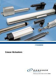
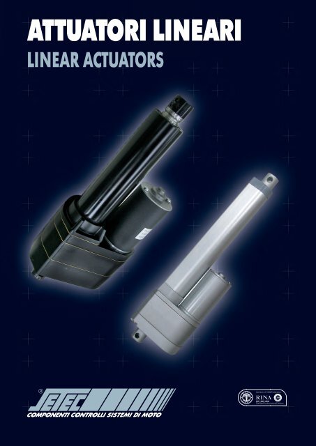
<strong>ATTUATORI</strong> <strong>LINEARI</strong><br />
LINEAR ACTUATORS
<strong>ATTUATORI</strong> <strong>LINEARI</strong><br />
LINEAR ACTUATORS<br />
N.B.: Il Gruppo SETEC si riserva il diritto di apportare al presente catalogo tutte le modifiche che si renderanno necessarie senza<br />
preavviso e non si assume nessuna responsabilità per errata interpretazione dello stesso.<br />
SETEC Group reserves the right to carry out, without notice, any modification on this catalogue that might be considered<br />
necessary and will not have any responsability for misunderstanding of the contents.
<strong>ATTUATORI</strong> <strong>LINEARI</strong><br />
Index LINEAR ACTUATORS<br />
1. Caratteristiche comuni / General features<br />
Indice / Index<br />
1.1.0 INTRODUZIONE / INTRODUCTION 1<br />
1.2.0 CARATTERISTICHE GENERALI / GENERAL FEATURES 1<br />
1.3.0 GAMME DI PRODOTTO / MODELS 2<br />
1.4.0 CAMPI APPLICATIVI / APPLICATIONS 4<br />
1.5.0 CARATTERISTICHE TECNICHE / TECHNICAL FEATURES 4<br />
1.5.1 Forza Nominale / Nominal Force 5<br />
1.5.2 Velocità Nominale / Nominal Speed 5<br />
1.5.3 Attuatori con vite trapezia acme (A)<br />
Actuator with acme screw (A) 5<br />
1.5.4 Attuatori con vite a ricircolo di sfere (B)<br />
Actuator with ball screw (B) 5<br />
1.5.5 Grado di protezione IP / IP Rating 5<br />
1.5.6 Motorizzazioni / Electric Motors 6<br />
1.6.0 FINECORSA E SISTEMI DI CONTROLLO DELLA CORSA<br />
LIMIT SWITCHES AND STROKE CONTROL SYSTEM 6<br />
1.6.1 Finecorsa pretarati in fabbrica “FC” (LD3, MD7 e FD)<br />
Preloaded limit switches in factory “FC” (LD3, MD7 and FD) 6<br />
1.6.2 Finecorsa regolabili “LT” (ID10, ID11, IA05 e LD6)<br />
Adjustable limit switches “LT” (ID10, ID11, IA05 and LD6) 7<br />
1.6.3 Finecorsa esterni “ERS” (ID12)<br />
Limit switches external “ERS” (ID12) 7<br />
1.6.4 Potenziometro “POT” / Potentiometer “POT” 8<br />
1.6.5 Sensore di Hall “HS” / Hall sensor “HS” 9<br />
1.6.6 Sensore Reed “RD” / Reed sensor “RD” 10<br />
2. Per applicazioni industriali / For industrial applications<br />
2.1.0 LD3 / LD3 11<br />
2.1.1 Caratteristiche / Characteristics 11<br />
2.1.2 Curve delle prestazioni / Performances curve 11<br />
2.1.3 Dimensioni / Dimensions 12<br />
2.1.4 Codice di ordinazione / Ordering code 12<br />
2.2.0 LD3 Silenzioso / Low noise LD3 13<br />
2.2.1 Caratteristiche / Characteristics 13<br />
2.2.2 Curve delle prestazioni / Performances curve 13<br />
2.2.3 Dimensioni / Dimensions 14<br />
2.2.4 Codice di ordinazione / Ordering code 14<br />
2.3.0 ID10 “Vite trapezia” / ID10 “Acme screw” 15<br />
2.3.1 Caratteristiche / Characteristics 15<br />
2.3.2 Curve delle prestazioni / Performances curve 15<br />
2.3.3 Dimensioni / Dimensions 16<br />
2.3.4 Codice di ordinazione / Ordering code 16
<strong>ATTUATORI</strong> <strong>LINEARI</strong> Indice<br />
2.4.0 ID10 “Vite a ricircolo di sfere” / ID10 “Ballscrew” 17<br />
2.4.1 Caratteristiche / Characteristics 17<br />
2.4.2 Curve delle prestazioni / Performances curve 17<br />
2.4.3 Dimensioni / Dimensions 18<br />
2.4.4 Codice di ordinazione / Ordering code 18<br />
2.5.0 ID11 “Vite trapezia” / ID10 “Acme screw” 19<br />
2.5.1 Caratteristiche / Characteristics 19<br />
2.5.2 Curve delle prestazioni / Performances curve 19<br />
2.5.3 Dimensioni / Dimensions 20<br />
2.5.4 Codice di ordinazione / Ordering code 20<br />
2.6.0 ID11 “Vite a ricircolo di sfere” / ID10 “Ballscrew” 21<br />
2.6.1 Caratteristiche / Characteristics 21<br />
2.6.2 Curve delle prestazioni / Performances curve 21<br />
2.6.3 Dimensioni / Dimensions 22<br />
2.6.4 Codice di ordinazione / Ordering code 22<br />
2.7.0 ID12 “Vite trapezia” / ID10 “Acme screw” 23<br />
2.7.1 Caratteristiche / Characteristics 23<br />
2.7.2 Curve delle prestazioni / Performances curve 23<br />
2.7.3 Dimensioni / Dimensions 24<br />
2.7.4 Codice di ordinazione / Ordering code 24<br />
2.8.0 ID12 “Vite a ricircolo di sfere” / ID10 “Ballscrew” 25<br />
2.8.1 Caratteristiche / Characteristics 25<br />
2.8.2 Curve delle prestazioni / Performances curve 25<br />
2.8.3 Dimensioni / Dimensions 26<br />
2.8.4 Codice di ordinazione / Ordering code 26<br />
2.9.0 IA05 “Vite trapezia” / IA05 “Acme screw” 27<br />
2.9.1 Caratteristiche / Characteristics 27<br />
2.9.2 Curve delle prestazioni / Performances curve 27<br />
2.9.3 Dimensioni / Dimensions 28<br />
2.9.4 Codice di ordinazione / Ordering code 28<br />
2.10.0 IA05 “Vite a ricircolo di sfere” / IA05 “Ballscrew” 29<br />
2.10.1 Caratteristiche / Characteristics 29<br />
2.10.2 Curve delle prestazioni / Performances curve 29<br />
2.10.3 Dimensioni / Dimensions 30<br />
2.10.4 Codice di ordinazione / Ordering code 30<br />
2.11.0 LD6 “Vite trapezia” / LD6 “Acme screw” 31<br />
2.11.1 Caratteristiche / Characteristics 31<br />
2.11.2 Curve delle prestazioni / Performances curve 31<br />
2.11.3 Dimensioni / Dimensions 32<br />
2.11.4 Codice di ordinazione / Ordering code 32
Index LINEAR ACTUATORS<br />
3. Per movimentazione pannelli solari / Solar panels handling<br />
3.1.0 ID10S “Vite trapezia” / “Vite a ricircolo di sfere” /<br />
ID10S “Acme screw” / “Ballscrew” 33<br />
3.1.1 Caratteristiche / Characteristics 33<br />
3.1.2 Curve delle prestazioni / Performances curve 34<br />
3.1.3 Dimensioni / Dimensions 34<br />
3.1.4 Codice di ordinazione / Ordering code 34<br />
4. Per applicazioni home-care, fitness e medicale / Home-care, fitness and medical application<br />
4.1.0 FD / FD 35<br />
4.1.1 Caratteristiche / Characteristics 35<br />
4.1.2 Curve delle prestazioni / Performances curve 36<br />
4.1.3 Dimensioni / Dimensions 36<br />
4.1.4 Codice di ordinazione / Ordering code 36<br />
4.2.0 MD7 “Vite trapezia” / “Vite a ricircolo di sfere” /<br />
MD7 “Acme screw” / “Ballscrew” 37<br />
4.2.1 Caratteristiche / Characteristics 37<br />
4.2.2 Curve delle prestazioni / Performances curve 38<br />
4.2.3 Dimensioni / Dimensions 38<br />
4.2.4 Codice di ordinazione / Ordering code 38<br />
5. Accessori / Accessories<br />
5.1.0 ALIMENTATORI E CONTROLLI ELETTRONICI /<br />
ELECTRONICS CONTROL AND POWER SUPPLIES 39<br />
5.1.1 Caratteristiche tecnico funzionali / Technical functional features 39<br />
5.1.2 Modalità di funzionamento / Working modes 39<br />
5.2.0 PULSANTIERE E CONNETTORE / HANDSET AND CONNECTOR 40<br />
5.3.0 TABELLE / TABLES 41<br />
5.4.0 CARATTERISTICHE TECNICHE E CODICI DI ORDINAZIONE /<br />
TECHNICAL FEATURES AND ORDERING CODE 43
La gamma degli attuatori Moteck / The range of Moteck actuators<br />
LD3<br />
ID12 ACME / BALLSCREW<br />
ID10S ACME / BALLSCREW<br />
ID10 ACME / BALLSCREW<br />
IA05 ACME / BALLSCREW<br />
FD<br />
ID11 ACME / BALLSCREW<br />
LD6 ACME<br />
MD7 ACME / BALLSCREW
<strong>ATTUATORI</strong> <strong>LINEARI</strong><br />
1. Caratteristiche comuni<br />
1.1.0 INTRODUZIONE<br />
MOTECK è un’azienda con sede in Taiwan che opera nel settore<br />
della movimentazione lineare elettrica da molti anni. La gamma<br />
degli elettrocilindri è vasta ed è tale da coprire i più svariati settori<br />
industriali e civili. L’azienda MOTECK è certificata ISO 9001:2008,<br />
sinonimo di qualità e di affidabilità del processo e del prodotto.<br />
La compattezza e l’elevata capacità di carico degli elettrocilindri<br />
MOTECK consente di poter applicare il prodotto in settori difficili<br />
come l’agricoltura, il navale e il medicale.<br />
Le opzioni di controllo della corsa come potenziometri o sensori ad<br />
effetto Hall consentono controlli precisi della posizione con grande<br />
semplicità di utilizzo.<br />
Gli elettrocilindri MOTECK possono essere alimentati con motori AC<br />
e DC (12V, 24V, 36V) e, nelle versioni dedicate al settore medicale,<br />
homecare e fitness, dispongono di control box ed handset per il<br />
controllo remoto dal design elegante e curato.<br />
1.2.0 CARATTERISTICHE GENERALI<br />
Gli elettrocilindri rientrano nella categoria degli attuatori lineari,<br />
dispositivi atti a trasformare il moto rotatorio, tipicamente di un<br />
motore elettrico, in moto lineare. Per tale ragione, in tutte quelle<br />
applicazioni in cui occorre spostare, sollevare, posizionare o tirare,<br />
un elettrocilindro rappresenta la soluzione più economica ad oggi<br />
esistente.<br />
Rispetto ad attuatori lineari tradizionali di tipo pneumatico o<br />
idraulico, infatti, gli elettrocilindri sono contraddistinti da maggiore<br />
semplicità costruttiva, una ridotta manutenzione, una estrema<br />
flessibilità, la non necessità di impianti a fluido preesistenti e la<br />
conseguente assenza di trafilaggi e perdite di olio non compatibili<br />
con settori particolari come l’homecare e il medicale.<br />
In linea generale un attuatore elettrico è da preferirsi ad un tradizionale<br />
cilindro idraulico o pneumatico per i seguenti vantaggi:<br />
• Minor costo di utilizzo;<br />
• Minor costo dei componenti;<br />
• Semplicità e rapidità di istallazione;<br />
• Costanza di rendimento e invariabilità di prestazione con la<br />
temperatura/umidità;<br />
• Nessun cambio olio e costi di smaltimento;<br />
• Impatto ambientale nullo;<br />
• Sistemi di controllo della posizione programmabili per riposizionamenti<br />
precisi e costanti nel tempo;<br />
• Basse potenze richieste;<br />
• Maggiore sicurezza per effetto della mancanza di fluidi in<br />
pressione potenzialmente pericolosi;<br />
• Possibilità di adottare comandi a distanza;<br />
• Scarsissima manutenzione dovuta alla semplicità costruttiva.<br />
La gamma di elettrocilindri MOTECK può ricoprire, in termini di forza<br />
nominale e velocità, la gran parte delle applicazioni nei più svariati<br />
settori dell’automazione industriale e non.<br />
Dalla serie più leggera agli attuatori della serie pesante il range di<br />
forze va dai 1000 N dell’attuatore LD3 ai 7000 N dell’ID10 con vite<br />
a ricircolo di sfere.<br />
Le velocità vanno da 6 a 65 mm/s in base al modello e in base al<br />
rapporto di riduzione e passo vite adottato.<br />
I motori elettrici AC e DC, con tensione di alimentazione di 12 e 24 V,<br />
1. Common features<br />
LINEAR ACTUATORS<br />
1.1.0 INTRODUCTION<br />
MOTECK is a company based in Taiwan that has been working in the<br />
field of electric linear motion for several years. The range of linear<br />
motion is wide and covers industrial and civil areas. The company<br />
MOTECK is certified ISO 9001:2008, synonymous of quality and<br />
reliability of the process and of the product.<br />
The compactness and the high carrying capacity of electro-cylinder<br />
MOTECK allow them to be used in difficult areas as agriculture,<br />
marine and medical applications.<br />
Option for stroke control such as potentiometer or Hall sensors allow<br />
precise and easy position control.<br />
MOTECK electro-cylinders can be powered with AC and DC (12V,<br />
24V, 36V) motors and in the medical field, homecare and fitness can<br />
be equipped with a nice designed control box and a handset for the<br />
remote control.<br />
1.2.0 GENERAL FEATURES<br />
Electro-cylinders belong to the family of the linear actuators, devices<br />
suitable to convert the rotary motion of an electric motor into linear<br />
motion. In every area where it is required to move, to lift, to have a<br />
fixed position,to push or to pull, the electro-cylinder is the cheapest<br />
solution ever.<br />
Compared to the traditional pneumatic or hydraulic linear actuator,<br />
the electro-cylinders are characterized by a great simplicity of<br />
construction, reduced maintenance, extreme flexibility, not required<br />
pre-existing fluid plant and consequent absence of leakages of oil<br />
not compatible with homecare and medical applications.<br />
In general terms an electric actuator is to be preferred to a conventional<br />
hydraulic or pneumatic cylinder for the following benefits:<br />
• Low cost of use;<br />
• Low cost of components;<br />
• Quick and easy installation;<br />
• Constancy of efficiency and unchanged performances with<br />
temperature/humidity<br />
• No oil change and disposal costs;<br />
• No environment impact;<br />
• Programmable position control system for precise and constant<br />
positioning;<br />
• Low power required;<br />
• Great safety due to the absence of potentially dangerous fluids<br />
under pressure;<br />
• Possibility to use remote controls;<br />
• Low maintenance due to the simplicity of construction.<br />
The range of MOTECK electro-cylinders can fulfil, in terms of nominal<br />
force and speed, most applications in several fields of industrial<br />
automation and others.<br />
From the light series of actuators till the heavy ones the range of<br />
forces goes from 1000 N of LD3 to 7000 N of ID10 with ballscrew.<br />
The speed goes from 6 to 65 mm/s depending on the model and<br />
based on the ratio and the screw lead.<br />
AC single phase or DC electric motors, with input voltage of 12V -<br />
24V, through worm screw gears or spur gears power transmission,<br />
1
<strong>ATTUATORI</strong> <strong>LINEARI</strong> Caratteristiche comuni<br />
mediante rinvii ortogonali a vite senza fine o paralleli ad ingranaggi,<br />
trasmettono il moto alla vite, trapezia o a ricircolo di sfere, che ingrana<br />
con una madrevite a cui è collegato lo stelo traslante.<br />
Solo i migliori materiali sono stati adottati per raggiungere lo standard<br />
qualitativo e di affidabilità richiesto oggi dal mercato.<br />
È stato fatto largo uso di materiali plastici rinforzati, ingranaggi<br />
sinterizzati, acciaio inox e alluminio grazie a cui è stato possibile dare<br />
al prodotto l’aspetto di robustezza e di finitura che lo contraddistingue.<br />
Gli stessi componenti sono stati progettati per soddisfare la richiesta<br />
di elevata durata al fine di incrementare la produttività dei macchinari<br />
che incorporano gli elettrocilindri.<br />
give rotary motion to the trapezoidal screw or to the ball screw, which<br />
then converts it into linear motion by the nut which is connected to<br />
the travelling rod.<br />
Only the best materials have been adopted to reach the standard of<br />
quality and reliability required by the market.<br />
Reinforced plastic materials, sintered gears, stainless steel and<br />
aluminium have been used and thanks to that it had been possible to<br />
give to the product that sturdiness aspect and a nice finishing touch.<br />
The same components have been designed to satisfy the request of<br />
long service life in order to increase the productivity of the machinery,<br />
where are assembled the electro-cylinders.<br />
1.3.0 GAMME DI PRODOTTO<br />
A seconda della destinazione d’uso sono state progettate gamme<br />
di prodotto che garantiscono le performance necessarie nell’ambito<br />
applicativo di riferimento.<br />
Le gamme di elettrocilindri disponibili sono le seguenti:<br />
• Attuatori per applicazioni industriali.<br />
Rappresenta la gamma high-level, progettati per soddisfare le<br />
sempre crescenti richieste di un settore altamente competitivo<br />
come quello industriale in genere, dell’automazione e delle<br />
macchine agricole. Sono elettrocilindri caratterizzati da notevoli<br />
forze e velocità, robusti ed affidabili e con i gradi di protezione IP<br />
più elevati e con la maggiore possibilità di controllo della corsa per<br />
una precisione di posizionamento e un feedback sulla posizione<br />
più accurato possibile.<br />
• Attuatori per movimentazione pannelli solari.<br />
È la gamma di attuatori con la maggiore resistenza agli agenti<br />
atmosferici e con il maggior numero di opzioni possibili per il<br />
feedback di posizione della corsa. La speciale staffa di cui sono<br />
dotati questi elettrocilindri consente di movimentare il pannello<br />
solare mantenendo un ingombro contenuto dell’attuatore.<br />
• Attuatori per applicazioni home-care, fitness e medicale.<br />
Rappresenta la gamma di design dell’intera produzione. La<br />
compattezza e l’aspetto curato che la contraddistingue consente<br />
una integrazione ottimale in quei sistemi che ciascuno di noi è<br />
abituato a vedere nelle proprie case, in ufficio e in palestra che ci<br />
aiutano nelle attività quotidiane. Sono tutti corredati di control box<br />
dal design curato ed elegante e di sistemi di comando a distanza<br />
come handset etc. L’aspetto ricercato e gradevole è un must per<br />
tali oggetti a cui si accompagna una affidabilità totale e una elevata<br />
qualità.<br />
Sono attuatori che possono essere impiegati anche nel settore<br />
medicale pertanto a complemento possono essere corredati da<br />
sistemi di sicurezza, obbligatori quando la movimentazione avviene<br />
in presenza di persone, come chiocciola di sicurezza o dispositivo<br />
“push only”.<br />
1.3.0 MODELS<br />
According to the use, a proper range of products has been designed<br />
to provide the required performance in the referred application.<br />
The available range of electro-cylinders is the following:<br />
• Actuators for industrial applications.<br />
It is the top level range, designed to meet the growing demands of<br />
a highly competitive sector such as industry in general, automation<br />
and agricultural machines. Electro-cylinders are characterized by<br />
remarkable forces and speeds, they are robust and reliable with<br />
high IP rating and with the possibility to control the stroke for<br />
a positioning accuracy and the most accurate feedback for the<br />
positions possible.<br />
• Actuators for solar panels handling.<br />
It is the range of actuators with greater resistance to outdoor<br />
applications and with the larger number of possible options for<br />
the feedback of the positioning of the stroke. The special bracket<br />
of these electro-cylinders allows to move the solar panel keeping<br />
a compact size of the actuator.<br />
• Actuators for home-care, fitness and medical application.<br />
It is the best looking series of the whole production. Its<br />
compactness and its nice aspect allow the best integration in<br />
systems we are used to see in our houses, offices and gym clubs<br />
and which help us during daily activities. They are all equipped<br />
with a nice designed and elegant control box and a remote<br />
control as a handset. The refined and pleasant appearance is<br />
compulsory for these objects together with a total reliability and<br />
a high quality.<br />
They can be used also in the medical field, therefore they can be<br />
equipped with safety system, compulsory when the handling is<br />
done for people, such as safety nut or a device “push only”.<br />
2
Common features LINEAR ACTUATORS<br />
Attuatori per applicazioni industriali / Actuators for industrial application<br />
LD3<br />
ID10 A+B<br />
ID11 A+B<br />
ID12 A+B<br />
IA05 A+B<br />
LD6<br />
Attuatori per movimentazione pannelli solari / Actuators for solar panel handling<br />
ID10S A+B<br />
Attuatori per applicazioni home-care, fitness e medicale / Actuators for home-care, fitness and medical sector<br />
LD3<br />
FD<br />
MD7<br />
3
<strong>ATTUATORI</strong> <strong>LINEARI</strong> Caratteristiche comuni<br />
1.4.0 CAMPI APPLICATIVI<br />
1.4.0 APPLICATIONS<br />
Attuatori per applicazioni industriali / Actuators for industrial applications<br />
• AUTOMAZIONE IN GENERE<br />
(trasportatori, imballaggio,<br />
pick and place, ecc)<br />
• MACCHINE AGRICOLE<br />
• MACCHINE MOVIMENTO<br />
TERRA<br />
• NAUTICA<br />
LD3<br />
ID12 A+B<br />
ID10 A+B<br />
IA05 A+B<br />
ID11 A+B<br />
LD6<br />
• GENERAL AUTOMATION<br />
(conveyor, packaging, pick<br />
and place, ecc)<br />
• AGRICULTURAL MACHINES<br />
• EARTH MOVING MACHINES<br />
• MARINE INDUSTRY<br />
Attuatori per movimentazione pannelli solari / Actuators for solar panels handling<br />
ID10S A+B<br />
Attuatori per applicazioni home-care, fitness e medicale / Actuators for home-care, fitness and medical sector<br />
• SOLLEVAMENTO PAZIENTI<br />
• MOVIMENTO LETTI<br />
• REGOLAZIONE SEDUTA<br />
• REGOLAZIONE TAVOLI<br />
• MACCHINE OSPEDALIERE<br />
• PORTE AUTOMATICHE<br />
LD3<br />
FD<br />
MD7<br />
• LIFTING PATIENTS DEVICES<br />
• BEDS MOVEMENTS<br />
• ADJUSTING CHAIRS<br />
• ADJUSTING TABLES<br />
• HOSPITAL MACHINES<br />
• AUTOMATIC DOORS<br />
1.5.0 CARATTERISTICHE TECNICHE<br />
1.5.0 TECHNICAL FEATURES<br />
LD3 LD3Q ID10A ID10B ID11A ID11B ID12A ID12B IA05A IA05B LD6 ID10SA ID10SB FD MD7<br />
Tensione alimentazione<br />
Input Voltage<br />
Massima forza nominale<br />
Maximum nominal force<br />
Massima velocità nominale<br />
Maximum nominal speed<br />
Massima corsa nominale<br />
Maximum nominal stroke<br />
Tipologia vite<br />
Screw type<br />
Diametro vite<br />
Screw diameter<br />
Max passo vite<br />
Max screw lead<br />
Ratio per max velocità<br />
Ratio for max speed<br />
Massimo duty cycle<br />
Maximum duty cycle<br />
Massima classe protezione<br />
Maximum IP rating<br />
[V]<br />
12/24<br />
DC<br />
115/230<br />
AC<br />
[N] 1000 800 3500 7000 3500 7000 3500 7000 3500 7000 2800 5500 9000 6000 6000<br />
[mm/s] 45 6 35 65 35 65 35 65 28 65 8,2 5,5 5,5 8,3 8,3<br />
[mm] 300 300 600 600 600 600 600 600 600 600 100 900 900 400 400<br />
acme acme acme<br />
24/36<br />
DC<br />
ricircolo<br />
ballscrew acme ricircolo<br />
ballscrew acme ricircolo<br />
ballscrew acme ricircolo<br />
ballscrew acme acme ricircolo<br />
ballscrew<br />
12/24<br />
DC<br />
12/24<br />
DC<br />
acme acme<br />
[mm] 10 10 20 16 20 16 20 16 20 16 20 20 15 14 14<br />
[mm] 3 3 5 5 5 5 5 5 5 5 4 5 5 8 8<br />
5 20 10 5 10 5 10 5 10 5 22 30 30 40 40<br />
% 25 25 25 25 25 25 25 25 25 25 25 25 25 10 10<br />
IP 65 65 65 65 65 65 65 65 65 65 40 65 65 40 54<br />
4
Common features LINEAR ACTUATORS<br />
1.5.1 Forza Nominale<br />
Il valore di forza nominale indicato nella tabella rappresenta il<br />
valore massimo che si vuole fare esercitare dall’attuatore sul carico<br />
in condizioni di sicurezza, sia in termini strutturali che di durata<br />
operativa utile.<br />
È da intendersi pertanto come massima portata nominale<br />
dell’attuatore nella fase di lavoro; laddove espressamente indicato<br />
nelle pagine seguenti, il valore di forza massima può anche essere<br />
espressa come massima forza statica e, a seconda della tipologia<br />
dell’attuatore, potrebbe esserci una differenziazione tra massima<br />
forza statica e dinamica in spinta o tiro.<br />
Vedere per maggiore dettaglio i paragrafi relativi ad ogni singolo<br />
attuatore.<br />
Tali valori, siano essi statici o dinamici, in spinta o in tiro, devono<br />
essere considerati quindi come il valore massimo di progetto<br />
richiesto all’attuatore per un corretto funzionamento e per evitare<br />
danni allo stesso.<br />
L’attuatore è un componente atto a vincere solo ed esclusivamente<br />
forze puramente assiali (lungo l’asse dell’attuatore).<br />
Nessuna forza disassata o radiale può essere supportata<br />
dall’attuatore; è altresì buona norma verificare sempre la bontà<br />
dell’allineamento dei punti di ancoraggio dell’attuatore.<br />
Si ricorda inoltre che sono da evitarsi condizioni di lavoro frequente in<br />
cui l’attuatore si trovi nella condizione di battuta meccanica.<br />
1.5.2. Velocità Nominale<br />
È il valore della velocità di traslazione dell’asta indicato nelle tabelle di<br />
questo catalogo e rappresenta il valore della velocità di rotazione del<br />
motore alimentato nelle condizioni di targa pari alla forza nominale.<br />
1.5.3. Attuatori con vite trapezia acme (A)<br />
Le versioni con vite trapezia sono generalmente adatte alle<br />
applicazioni dove il numero di manovre nell’unità di tempo è ridotto,<br />
a causa del riscaldamento dell’insieme vite-madrevite, dove la<br />
precisione richiesta non è elevata, dove l’usura nel tempo non crea<br />
inconvenienti e dove non sono richieste grandi forze e grandi velocità<br />
allo stesso tempo.<br />
Per contro le vite trapezia garantisce l’irreversibilità del sistema<br />
eccesso in casi di viti con passo molto lungo.<br />
1.5.4. Attuatori con vite a ricircolo di sfere (B)<br />
Le versioni con vite a ricircolazione di sfere sono adatte generalmente<br />
per le applicazioni dove il numero di manovre nell’unità di tempo<br />
è più elevato, dove la precisione richiesta è elevata e tale deve<br />
rimanere nel tempo, e dove sono richieste congiuntamente grandi<br />
forze e velocità.<br />
L’elevato rendimento della trasmissione richiede a parità di forza<br />
esterna una coppia inferiore pertanto l’efficienza del sistema è<br />
notevolmente superiore.<br />
Di contro l’attuatore risulta reversibile pertanto è indispensabile<br />
l’utilizzo di sistemi atti ad arrestare l’arretramento dello stelo sotto<br />
carico.<br />
1.5.5. Grado di protezione IP<br />
Il grado di protezione di ciascun attuatore varia a seconda del modello<br />
e della destinazione d’uso.<br />
Alcune tipologie di attuatori sono fornibili in alternativa, come<br />
opzione, con gradi di protezione maggiori rispetto alla configurazione<br />
standard.<br />
1.5.1 Nominal Force<br />
The value of nominal force indicated on the chart is the maximum<br />
value that the actuator apply on the load in safety conditions, either<br />
in terms of structure or useful lifetime.<br />
It is then the maximum nominal load on the actuator during the<br />
working phase (in motion); in some cases this value can be also the<br />
maximum static force on the actuator.in some others there could be<br />
a difference between push and pull values.<br />
For more information see the paragraphs of each actuator.<br />
These values, either static or dynamic, either pulling or pushing, should<br />
be considered as the maximum value in the required application, for<br />
proper functioning and in order to avoid damages during the life of the<br />
actuator.<br />
The actuator is a product able to manage only axial forces (along the<br />
axis of the actuator).<br />
No radial or offset forces can be supported by the actuator, it’s<br />
important then to check the correct alignment of the connection<br />
points of the actuator.<br />
Please remember to avoid frequent working conditions where<br />
the actuator goes to its stroke end and uses its internal parts as<br />
mechanical stop.<br />
1.5.2. Nominal Speed<br />
It’s the value of linear speed of the rod indicated in the chart of this<br />
catalogue and corresponds to the value of rotational speed of the<br />
motor in nominal supply condition, by which we get the nominal force.<br />
1.5.3. Actuator with acme screw (A)<br />
The versions with acme screw are recommended where the number<br />
of cycles is reduced, due to the heating of the screw and the nut,<br />
where the precision required is not too high, where the wear during<br />
the lifetime does not create problems and where high force and<br />
speed are not required.<br />
1.5.4. Actuator with ballscrew (B)<br />
The versions with ballscrews are recommended where the number<br />
of duty cycles is higher, where the required accuracy is higher and<br />
constant, and where are also required higher forces and higher<br />
speeds.<br />
The high efficiency of the transmission requires with the same force<br />
a lower torque, therefore the efficiency of the system is considerably<br />
higher.<br />
The actuator is reversible and it’s essential to use devices to stop<br />
the backward movement of the rod under load.<br />
1.5.5. IP Rating<br />
IP rating of each actuator changes according to the model.<br />
Some types of actuators can be equipped, as an option, with IP rating<br />
higher than the standard configuration.<br />
5
<strong>ATTUATORI</strong> <strong>LINEARI</strong> Caratteristiche comuni<br />
1ª cifra<br />
1 nessuna protezione;<br />
2 protetto contro corpi solidi superiori a 50 mm (es. contatti<br />
involontari con la mano);<br />
3 protetto contro corpi solidi superiori a 12 mm (es. dita della<br />
mano);<br />
4 protetto contro corpi solidi superiori a 2.5 mm (es. attrezzi, fili);<br />
5 protetto contro corpi solidi superiori a 1 mm (es. piccoli attrezzi,<br />
piccoli fili);<br />
6 protetto contro l’ingresso di polveri la cui quantità potrebbe<br />
essere nociva;<br />
7 protetto contro l’ingresso di polveri.<br />
2ª cifra<br />
1 nessuna protezione;<br />
2 protetto contro la caduta verticale di gocce d’acqua (condensa);<br />
3 protetto contro la caduta di gocce d’acqua fino a 15° dalla<br />
verticale;<br />
4 protetto contro la pioggia fino a 60° dalla verticale;<br />
5 protetto contro le proiezioni d’acqua da ogni direzione;<br />
6 protetto contro i getti d’acqua da ogni direzione con la lancia;<br />
7 protetto contro le proiezioni d’acqua simili a onde marine.<br />
1 st Digit<br />
1 no protection;<br />
2 Protection against solid objects up to 50 mm (eg.: accidental<br />
touch by hands);<br />
3 Protection against solid objects up to 12 mm (eg.: fingers);<br />
4 Protection against solid objects up to 2,5 mm (eg.: tools and<br />
wires);<br />
5 Protection against solid objects up to 1 mm (eg.: small tools and<br />
small wires);<br />
6 Protection against dust whose quantity can be annoying;<br />
7 Protection against dust entry.<br />
2 nd Digit<br />
1 no protection;<br />
2 Protection against drops of water falling vertically (condensation);<br />
3 Protection against direct drops of water up to 15° from vertical<br />
line;<br />
4 Protection against direct drops of water up to 60° from vertical<br />
line;<br />
5 Protection against water sprayed from all directions;<br />
6 Protection against water jets from any direction with a spear;<br />
7 Protection against jets of water similar to sea waves.<br />
1.5.6. Motorizzazioni<br />
I motori elettrici installati di serie negli attuatori possono essere,<br />
a seconda del modello, in corrente continua, 12/24/36 VDC, o AC<br />
monofase a 115/230 V.<br />
Il tipo di motore installato consente all’attuatore le performance<br />
dichiarate in questo catalogo in termini di velocità, forza e corrente<br />
assorbita.<br />
I motori installati non sono autofrenanti pertanto laddove<br />
l’efficienza del sistema sia elevata, soprattutto negli attuatori a vite<br />
a ricircolazione di sfere sono previsti sistemi per l’irreversibilità.<br />
1.6.0. FINECORSA E SISTEMI DI CONTROLLO DELLA<br />
CORSA<br />
A seconda della tipologia dell’attuatore e della destinazione d’uso,<br />
sono possibili svariati sistemi per il controllo della corsa e della<br />
posizione (per maggiore dettaglio vedere tabella seguente).<br />
1.5.6. Electric motors<br />
The electric motors installed can be in DC 12/24/36 VDC or in AC<br />
single phase 115/230 V.<br />
The type of motor installed allow the actuator the performance<br />
declared on this catalogue as speed, force and absorbed current.<br />
The motors installed aren’t with brake and whereas the efficiency<br />
should be higher, in particular in the ball screw actuator there is an<br />
internal braking system.<br />
1.6.0. LIMIT SWITCHES AND STROKE POSITION<br />
FEEDBACK DEVICES<br />
According to the type of the actuator and the application, there are<br />
several possible stroke position feedback devices (see following<br />
chart).<br />
DISPOSITIVI PER IL CONTROLLO DELLA CORSA<br />
STROKE POSITION FEEDBACK<br />
STANDARD O OPZIONALI (*)<br />
STANDARD OR OPTIONS (*)<br />
FINECORSA NON REGOLABILE (FC)<br />
NOT ADJUSTABLE LIMIT SWITCHES (FC)<br />
FINECORSA REGOLABILE (LT)<br />
ADJUSTABLE LIMIT SWITCHES (LT)<br />
FINECORSA ESTERNO REED “ERS”<br />
EXTERNAL REED LIMIT SWITCHES “ERS”<br />
SENSORE DI POSIZIONE “REED”<br />
“REED” SENSOR POSITION<br />
SENSORE DI POSIZIONE HALL<br />
HALL SENSOR POSITION<br />
POTENZIOMETRO<br />
POTENTIOMETER<br />
<strong>ATTUATORI</strong> / ACTUATORS<br />
LD3 LD3Q ID10A ID10B ID11A ID11B ID12A ID12B IA05A IA05B LD6 ID10SA ID10SB FD PD MD7<br />
X X X X X<br />
X X X X X X X X X<br />
X X<br />
X X<br />
X X X X X X X<br />
X X X X X X X X<br />
(*) per alcuni modelli non possono coesistere nello stesso attuatore tutti i dispositivi elencati - vedere i paragrafi specifici /<br />
for some models all the listed options can’t coexist in the same actuator – see specific paragraphs<br />
6
Common features LINEAR ACTUATORS<br />
Di seguito un elenco e una breve descrizione dei sistemi adottati.<br />
1.6.1. Finecorsa pretarati in fabbrica “FC” (LD3,<br />
MD7 e FD)<br />
Sono finecorsa meccanici di tipo microswitch montati all’interno<br />
dell’elettrocilindro con unica funzione di arresto del motore nella<br />
posizione iniziale e finale. Sono adottati negli attuatori LD3, MD7<br />
e FD. Sono assemblati, cablati e pretarati in fabbrica pertanto la<br />
posizione non è regolabile (posizione tutta retratta e tutta estesa).<br />
Here below a short description of the availoable systems.<br />
1.6.1. Factory-set limit switches “FC” (LD3, MD7<br />
and FD)<br />
They are mechanical limit switches micro-switch type assembled<br />
inside the electro-cylinder with a single function to stop the motor in<br />
the initial and final position. They are on the actuators LD3, MD7 and<br />
FD. They are assembled, wired and set in the factory, therefore the<br />
position is not adjustable (completely retracted or extended).<br />
1.6.2. Finecorsa regolabili “LT” (ID10, ID11, IA05 e<br />
LD6)<br />
Sono finecorsa meccanici di tipo microswitch montati all’interno<br />
dell’elettrocilindro.<br />
Quando attivati, interrompono l’alimentazione al motore nella<br />
direzione che ha raggiunto la posizione finale o iniziale. Verso<br />
l’esterno (eventuali controlli tipo PLC) non sono disponibili connessioni<br />
elettriche che segnalano l’attivazione dei finecorsa.<br />
I finecorsa sono azionati da delle camme. È possibile regolare<br />
manualmente le due posizioni di finecorsa ruotando la posizione di<br />
ciascuna camma e bloccandola nella posizione desiderata.<br />
Le camme di regolazione sono situate all’interno della culatta<br />
dell’attuatore.<br />
1.6.2. Adjustable limit switches “LT” (ID10, ID11,<br />
IA05 and LD6)<br />
They are mechanical limit switches microswitch type assembled<br />
inside the electro-cylinder.<br />
When on, they interrupt the power to the motor according to the<br />
direction which had reached the initial or final position.<br />
Electrical connections which indicates the activation of the limit<br />
switches are not available (e.g. PLC controls).<br />
Limit switches are driven by cams. It’s possible to adjust manually the<br />
two positions of the limit switches, turning the position of each cam<br />
and locking it in the required position.<br />
The cams are inside then rear carter of the actuator.<br />
Regolazione dei finecorsa:<br />
La posizione di estensione massima viene regolata mediante la<br />
camma superiore, mentre la posizione di stelo completamente<br />
retratto viene regolata mediante la camma inferiore.<br />
Qualora fosse necessario regolare la posizione dei finecorsa, attenersi<br />
alla procedura seguente:<br />
1. Nel caso in cui l’attuatore sia già stato istallato, smontarlo e aprire<br />
la scatola del riduttore per settare le camme.<br />
2. Far retrarre lo stelo mediante il motore finché la camma inferiore<br />
raggiunge il finecorsa; in quel momento il motore si arresterà.<br />
Ruotare in senso orario o antiorario il tubo interno fino a raggiungere<br />
la posizione desiderata. In questo modo viene fissata la posizione<br />
di stelo completamente retratto.<br />
3. Portare lo stelo alla posizione di massima estensione desiderata<br />
mediante il motore, quindi regolare la camma superiore fino al<br />
contatto con il finecorsa superiore. In questo modo viene fissata la<br />
posizione di stelo completamente esteso.<br />
Limit switches adjustment:<br />
The maximum extended position is adjusted by the upper cam, and<br />
the maximum retracted position is adjusted by the lower cam.<br />
Whether it is necessary to adjust the limit switches position, follow<br />
this below procedure:<br />
1. If the actuator is already installed, disassembled it, and open the<br />
gearbox to set the cams.<br />
2. Retract the rod using the motor until the lower cam reach the limit<br />
switches; the motor will stop.<br />
Turn in clockwise or anticlockwise the internal tube until it reaches<br />
the required position. In that way the position of the rod fully<br />
retracted is set.<br />
3. Bring the rod in the position of maximum required extension<br />
using the motor, then adjust the upper cam until it touches the<br />
upper limit switch. In that way the fully extended position of the<br />
rod is set.<br />
7
<strong>ATTUATORI</strong> <strong>LINEARI</strong> Caratteristiche comuni<br />
1.6.3. Finecorsa esterni “ERS” (ID12)<br />
Sono finecorsa magnetici montati esternamente all’elettrocilindro<br />
e sono sensori di segnale, e non di potenza, ovvero non tagliano<br />
l’alimentazione all’attuatore. Sono adottati negli attuatori della serie<br />
ID12. Il corpo esterno di questi attuatori presenta su ciascun lato una<br />
cava lungo la quale è possibile far scorrere e bloccare nella posizione<br />
desiderata i finecorsa. In casi particolari è possibile inserire sulla<br />
stessa cava più di due sensori per segnalare anche il raggiungimento<br />
o il passaggio di posizioni intermedie.<br />
1.6.4. Potenziometro “POT”<br />
Il potenziometro consente una misura “ASSOLUTA” della posizione<br />
dello stelo. Il potenziometro è collegato allo stelo del cilindro elettrico<br />
tramite un sistema d’ingranaggi meccanici. Il valore della resistenza<br />
del potenziometro indica in modo proporzionale la posizione dello<br />
stelo.<br />
Si ricorda che per la “lettura” del potenziometro e quindi della<br />
posizione dello stelo, occorre:<br />
1) Un alimentazione in DC (normalmente 5 o 10 V) uguale alla<br />
tensione massima prevista dal sistema elettronico di misura<br />
(interfaccia A/D).<br />
2) Un’interfaccia di conversione Analogico/Digitale sull’apparecchiatura<br />
di controllo (PLC, PC, etc.) con ingresso ad alta impedenza<br />
per una migliore linearità della conversione da analogico a digitale.<br />
3) Il programma sull’unità di controllo deve implementare il seguente<br />
calcolo:<br />
Posizione stelo = Corsa max. *(Tensione cursore Potenz./Tensione<br />
alimentazione Potenz.)<br />
Il potenziometro consente una retroazione di posizionamento efficace<br />
ed è molto semplice da attuare mediante lettura del segnale di output<br />
proporzionale alla corsa.<br />
La taratura viene fissata dalla fabbrica pertanto la regolazione<br />
non è possibile. (ATTENZIONE: se si svita lo stelo si perde questo<br />
riferimento!).<br />
Di seguito le caratteristiche del potenziometro.<br />
La resistenza è variabile in base al valore della corsa e della lunghezza<br />
1.6.3. External Limit switches “ERS” (ID12)<br />
They are limit switches of a magnetic type, assembled on the<br />
protection tube of the electro-cylinder; they are signal sensors, not of<br />
power, hence they do not cut power supply to the actuator. They are<br />
used on the actuators of ID12 series. The protection tube has a slot<br />
on 2 sides into which it’s possible to put and lock the limit switches<br />
in the desired position. In specific cases, it’s possible to insert on<br />
the same slot more than two limit switches to show the reaching of<br />
intermediate positions.<br />
1.6.4. Potentiometer “POT”<br />
The potentiometer allows an “ABSOLUTE” measurement of the rod<br />
position. Potentiometer is linked to the rod by a mechanical gear<br />
system.<br />
The value of the resistance of the potentiometer indicates in<br />
proportional way the rod position.<br />
Please note that to read potentiometer signal we need:<br />
1) A power supply in DC (5 or 10 V) equal to the maximum voltage<br />
expected from the electronic system of measurement (interface<br />
A/D).<br />
2) A conversion interface Analogic/Digital on the control system<br />
(PLC,PC, etc) with input at high impedance in order to improve<br />
the signal conversion from Analogic to Digital.<br />
3) The program of the control unit must implement the following<br />
calculation:<br />
Rod Position = Stroke max* (Voltage Cursor Potentiometer/<br />
Voltage Supply Potentiometer)<br />
Potentiometer allows an efficient positioning feedback and<br />
it’s easy to use by reading of output signal proportional to the<br />
stroke.<br />
Potentiometer calibration is done in the factory therefore the<br />
adjustment is not possible. (WARNING: If you unscrew the rod this<br />
reference is lost)<br />
Below the characteristics of potentiometer.<br />
The resistance is variable related to the stroke and the length as<br />
8
Common features LINEAR ACTUATORS<br />
utile secondo la tabella:<br />
shown in the chart.<br />
Valore del potenziometro / Value of Potentiometer<br />
Ohm misurati tra il cavo blu e il cavo bianco a corsa Ø mm e a corsa massima /<br />
Ohm measurement between the blue cable and the white cable at stroke Ø mm and at maximum stroke<br />
Corsa / Stroke<br />
(mm)<br />
Resistenza* / Resistance*<br />
100 0,3 - 8,0<br />
150 0,3 - 8,5<br />
200 0,3 - 9,1<br />
300 0,3 - 8,6<br />
457 0,3 - 9,2<br />
610 0,3 - 9,8<br />
Tolleranza: ± 0,3 kΩ su fondo scala / Tolerance: ± 0,3 kΩ full scale<br />
(kΩ)<br />
Corsa / Stroke<br />
Valore errore /<br />
Value of error<br />
Valore resistenza /<br />
Value resistance<br />
1.6.5. Sensore di Hall “HS”<br />
A differenza della retroazione basata sul Potenziometro, i sensori<br />
Hall non permettono una misura assoluta della posizione dello stelo.<br />
Questo sensore permette, tramite un magnete rotante montato<br />
sull’albero del motore, di generare uno o più impulsi elettrici per<br />
ogni rivoluzione del motore. È pertanto da considerarsi un sensore di<br />
posizione di tipo “INCREMENTALE”. Occorre cioè “contare” gli impulsi<br />
rispetto ad una posizione di riferimento (posizione zero).<br />
I sensori di Hall sono dei dispositivi elettronici, richiedono anch’essi<br />
un’alimentazione in bassa tensione DC (circa 5 Vdc) e i segnali<br />
generati sono di tipo digitale con i livelli di tensione uguali a circa<br />
quelli dell’alimentazione. Nella versione con due sensori Hall la forma<br />
in uscita dei due segnali è come quella dei segnali di un encoder<br />
(onde quadre sfasate di 90°). A seconda dell’interfaccia di conteggio<br />
prevista sull’unità di controllo, la risoluzione di “Impulsi/Giro” motore<br />
può essere moltiplicata per 1, 2 o 4.<br />
La risoluzione massima (conteggio x 1) è riportata in tabella.<br />
1.6.5. Hall Sensor “HS”<br />
Compared to the feedback of the Potentiometer, the Hall sensors<br />
don’t permit an absolute measurement of the rod position.<br />
These sensors allow, through a rotary magnet assembled on the<br />
motor shaft, to generate one or more electric impulses to every<br />
revolution of the motor. It means that this is an “INCREMENTAL “<br />
sensor of position of. You need to count the number of impulses with<br />
reference position (position 0).<br />
The Hall sensors are electronic devices which require a low<br />
voltage DC power (about 5 VDC) and the signals are of digital<br />
type with level of voltage more or less equal to the power supply.<br />
In the version with two Hall sensors the output shape of the two<br />
signals is similar to the ones of an encoder (square waves out of<br />
phase of 90°). According to the counting interface of the control<br />
unit, the resolution of motor “Impulse/Turn” could be multiplied<br />
by 1, 2 or 4.<br />
The maximum resolution (counting x 1) is shown in the chart.<br />
Sensore di Hall / Hall Sensor<br />
Rapporto riduzione / Gear Ratio<br />
Risoluzione / Resolution<br />
5:1 2,3<br />
10:1 3,6<br />
20:1 6,9<br />
30:1 10,6<br />
40:1 14,3<br />
(Impulsi / Pulses) [mm]<br />
9
<strong>ATTUATORI</strong> <strong>LINEARI</strong> Caratteristiche comuni<br />
In caso di n° 2 sensori di Hall la risoluzione è la medesima ma il<br />
secondo segnale sfasato di 90° consente alla ipotetica elettronica di<br />
pilotaggio di conoscere la direzione del movimento ed eventualmente,<br />
in base al tipo di centralina, di moltiplicare per quattro la risoluzione.<br />
In case of two Hall sensors, the resolution is the same but the second<br />
signal is out of phase of 90° and it allows the hypothetical electronic<br />
drive to know the direction of movement and, eventually according to<br />
the unit, to multiply by four times the resolution.<br />
Magnete / Magnet<br />
Sensore di Hall 1 /<br />
Hall Sensor 1<br />
Sensore di Hall /<br />
Hall Sensor<br />
Sensore di Hall 2 /<br />
Hall Sensor 2<br />
Magnete / Magnet<br />
1.6.6. Sensore Reed “RD”<br />
Le versioni con sensore Reed operano come nella versione Hall.<br />
Le differenze sono:<br />
1) Non è previsto il montaggio di un secondo sensore Reed. Non<br />
consente quindi il funzionamento come encoder (conteggio e<br />
direzione).<br />
2) Il Reed non richiede alimentazione.<br />
3) Il segnale in uscita è ottenuto dall’apertura/chiusura di un contatto<br />
meccanico azionato dal campo del magnete rotante. Il contatto<br />
deve essere utilizzato per commutare i livelli della tensione<br />
sull’ingresso di conteggio di un PLC.<br />
1.6.6. Reed Sensor “RD”<br />
The versions with Reed sensor work like the Hall version.<br />
The differences are:<br />
1) It is not possible to assemble a second Reed sensor. Hence it is<br />
not possible to work as an encoder (counting and direction).<br />
2) The Reed sensor does not require power supply.<br />
3) The output signal is obtained by opening/closing a mechanical<br />
contact activated by a field of rotary magnet. The contact must be<br />
used to commutate the levels of the voltage on the input of the<br />
PLC counting.<br />
Sensore Reed /<br />
Reed Sensor<br />
10
<strong>ATTUATORI</strong> <strong>LINEARI</strong><br />
2. Per applicazioni industriali<br />
2.1.0. LD3<br />
2. For industrial applications<br />
2.1.0. LD3<br />
LINEAR ACTUATORS<br />
Standard<br />
2.1.1. Caratteristiche<br />
Con potenziometro<br />
With potentiometer<br />
2.1.1. Characteristics<br />
Con sensore di Hall<br />
With Hall sensor<br />
• Tre versioni disponibili:<br />
- STANDARD<br />
- CON POTENZIOMETRO (POT)<br />
- CON SENSORE DI HALL (HS)<br />
• Finecorsa fissi pretarati e precablati in fabbrica alla corsa nominale;<br />
• Design compatto;<br />
• Prestazioni:<br />
- Velocità massima: 45 mm/sec (*)<br />
- Massima forza in spinta/tiro: 1000 N (*)<br />
- Ciclo di lavoro a 20°C: 25% (2.5 min ON, 7.5 min OFF)<br />
• Motorizzazione in corrente continua: 12VDC o 24 VDC;<br />
• Rapporti di riduzione disponibili: 5:1, 10:1, 20:1, 30:1, 40:1;<br />
• Corse standard disponibili [mm]: 50, 100, 150, 200, 250, 300;<br />
• Temperature di funzionamento: da -26°C a +65°C;<br />
• Vite trapezia Ø 10,5 passo 3;<br />
• Madrevite in materiale plastico PA66;<br />
• Ingranaggi di riduzione in materiale metallico;<br />
• Lo stelo e la camicia realizzati in lega di alluminio anodizzato;<br />
• La culatta posteriore in alluminio pressofuso integra l’attacco<br />
posteriore cilindrico con foro per fissaggio a perno;<br />
• L’attacco frontale cilindrico con foro per fissaggio a perno è<br />
integrale con lo stelo;<br />
• Grado di protezione standard IP54 (a richiesta IP65, non disponibile<br />
con Sensore di Hall);<br />
• Antirotazione integrata standard.<br />
(*) vedere Grafico 2.1.1 per le velocità possibili in funzione della forza e del<br />
rapporto di riduzione.<br />
• Three versions available:<br />
- STANDARD<br />
- WITH POTENTIOMETER (POT)<br />
- WITH HALL SENSOR (HS)<br />
• Factory-set and cabled limit switches for the nominal stroke;<br />
• Compact design;<br />
• Performances:<br />
- Speed Max: 45 mm/sec (*)<br />
- Max Dynamic Force push/pull: 1000 N (*)<br />
- Duty cycle at 20°C: 25% (2.5 min ON, 7.5 min OFF)<br />
• DC Motors 12VDC or 24 VDC;<br />
• Gear ratio: 5:1, 10:1, 20:1, 30:1, 40:1;<br />
• Available Strokes [mm]: 50, 100, 150, 200, 250, 300;<br />
• Working Temperature: from -26°C to +65°C;<br />
• Acme Screw Ø 10,5 lead 3;<br />
• Nut in plastic material PA66;<br />
• Metal gears;<br />
• Rod and cylinder in anodized aluminium alloy;<br />
• Rear cylindrical connection hole made on the cast-aluminium rear<br />
carter;<br />
• Front cylindrical connection hole integrated with the rod;<br />
• IP Standard Rating IP54 ( on request IP 65,not available with Hall<br />
sensor);<br />
• Antirotation device as a standard.<br />
(*) see Graph 2.1.1 for Speed range compared to load and ratio.<br />
2.1.2. Curve delle prestazioni 2.1.2. Performance curves<br />
Grafico 2.1.1: Velocità [mm/s] in funzione del carico [N]<br />
Graph 2.1.1: Speed [mm/s] vs Load [N]<br />
Grafico 2.1.2: Assorbimento [A] in funzione del carico [N]<br />
Graph 2.1.2: Current [A] vs Load [N]<br />
12V DC<br />
24V DC<br />
11
<strong>ATTUATORI</strong> <strong>LINEARI</strong> Per applicazioni industriali<br />
2.1.3. Dimensioni 2.1.3. Dimensions<br />
LD3 STANDARD<br />
lunghezza cavo<br />
cable length<br />
lunghezza cavo<br />
cable length<br />
lunghezza cavo<br />
cable length<br />
CORSA / STROKE<br />
50 100 150 200 250 300<br />
A [mm] 158 209 260 311 362 413<br />
A - vedere tabella / see chart<br />
DIMENSIONE FUNZIONE DELLA CORSA / DIMENSION RELATED TO THE STROKE<br />
A - vedere tabella / see chart<br />
DIMENSIONE FUNZIONE DELLA CORSA / DIMENSION RELATED TO THE STROKE<br />
CORSA / STROKE<br />
CORSA / STROKE<br />
LD3 POT<br />
lunghezza cavo<br />
cable length<br />
A - vedere tabella / see chart<br />
DIMENSIONE FUNZIONE DELLA CORSA / DIMENSION RELATED TO THE STROKE<br />
CORSA / STROKE<br />
lunghezza cavo<br />
cable length<br />
lunghezza cavo<br />
cable length<br />
A - vedere tabella / see chart<br />
DIMENSIONE FUNZIONE DELLA CORSA / DIMENSION RELATED TO THE STROKE<br />
CORSA / STROKE<br />
CORSA / STROKE<br />
50 100 150 200 250 300<br />
A [mm] 195 246 297 348 399 450<br />
A - vedere tabella / see chart<br />
DIMENSIONE FUNZIONE DELLA CORSA / DIMENSION RELATED TO THE STROKE<br />
A - vedere tabella / see chart<br />
DIMENSIONE FUNZIONE DELLA CORSA / DIMENSION RELATED TO THE STROKE<br />
CORSA / STROKE<br />
CORSA / STROKE<br />
LD3 HS<br />
lunghezza cavo<br />
cable length<br />
lunghezza cavo<br />
cable length<br />
lunghezza cavo<br />
cable length<br />
A - vedere tabella / see chart<br />
DIMENSIONE FUNZIONE DELLA CORSA / DIMENSION RELATED TO THE STROKE<br />
CORSA / STROKE<br />
A - vedere tabella / see chart<br />
DIMENSIONE FUNZIONE DELLA CORSA / DIMENSION RELATED TO THE STROKE<br />
CORSA / STROKE<br />
CORSA / STROKE<br />
50 100 150 200 250 300<br />
A [mm] 158 209 260 311 362 413<br />
A - vedere tabella / see chart<br />
DIMENSIONE FUNZIONE DELLA CORSA / DIMENSION RELATED TO THE STROKE<br />
CORSA / STROKE<br />
2.1.4. Codice di ordinazione<br />
2.1.4. Ordering code<br />
LD3 12 20 100 HS IP54<br />
VDC Ratio Corsa / Stroke Opzione / Option Protezione / Protection<br />
12<br />
24<br />
1:5<br />
1:10<br />
1:20<br />
1:30<br />
1:40<br />
50<br />
100<br />
150<br />
200<br />
250<br />
300<br />
–<br />
HS<br />
2HS<br />
POT<br />
54 (Standard)<br />
65<br />
HS: con 1 Sensore di Hall / with Hall Sensor - 2HS: con 2 sensori di Hall / with 2 Hall Sensors - POT: Potenziometro (esclude il sensore di Hall) / Potentiometer (excludes<br />
the Hall sensor)<br />
12
For industrial applications LINEAR ACTUATORS<br />
2.2.0. LD3 “silenzioso”<br />
2.2.0. Low noise LD3<br />
Standard<br />
2.2.1. Caratteristiche<br />
Con potenziometro<br />
With potentiometer<br />
2.2.1. Characteristics<br />
Con sensore di Hall<br />
With Hall sensor<br />
• Tre versioni disponibili:<br />
- STANDARD<br />
- CON POTENZIOMETRO (POT)<br />
- CON SENSORE DI HALL (HS)<br />
• Finecorsa fissi pretarati e precablati in fabbrica alla corsa nominale;<br />
• Design compatto;<br />
• Stesse caratteristiche dell’LD3 (ingranaggi in materiale plastico).<br />
• Prestazioni:<br />
- Velocità massima: 6 mm/sec (*)<br />
- Massima forza in spinta/tiro: 800 N (*)<br />
- Ciclo di lavoro a 25°C: 25% (2,5 min ON, 7,5 min OFF)<br />
• Motorizzazione in corrente continua 12VDC o 24 VDC;<br />
• Rapporti di riduzione disponibili: 20:1, 30:1;<br />
• Corse standard disponibili [mm]: 50, 100, 150, 200, 250, 300;<br />
• Temperature di funzionamento: da -26°C a +65°C;<br />
• Vite trapezia Ø 10,5 passo 3;<br />
• Madrevite in materiale plastico POM;<br />
• Ingranaggi di riduzione in materiale plastico per ridurre il rumore;<br />
• Lo stelo e la camicia sono realizzati interamente in lega di<br />
alluminio anodizzato;<br />
• La culatta posteriore in alluminio presso fuso integra l’attacco<br />
posteriore cilindrico con foro per fissaggio a perno;<br />
• L’attacco frontale cilindrico con foro per fissaggio a perno è<br />
integrale con lo stelo;<br />
• Grado di protezione standard IP54 (a richiesta IP65, non disponibile<br />
con Sensore di Hall);<br />
• Antirotazione integrata standard.<br />
(*) vedere Grafico 2.2.1 per le velocità possibili in funzione della forza e del<br />
rapporto di riduzione.<br />
• Three versions available:<br />
- STANDARD<br />
- WITH POTENTIOMETER (POT)<br />
- WITH HALL SENSOR (HS)<br />
• Factory-set and cabled limit switches for the nominal stroke;<br />
• Compact design;<br />
• Same characteristics of LD3<br />
• Performances:<br />
- Speed Max: 6 mm/sec (*)<br />
- Max Dynamic Force push/pull: 800 N (*)<br />
- Duty cycle at 20°C: 25% (2.5 min ON, 7.5 min OFF)<br />
• DC Motors 12VDC or 24 VDC;<br />
• Gear ratio: 20:1, 30:1;<br />
• Available Strokes [mm]: 50, 100, 150, 200, 250, 300;<br />
• Working Temperature: from -26°C to +65°C;<br />
• Acme Screw Ø 10,5 lead 3;<br />
• Nut in plastic material POM;<br />
• Reduction gears in plastic material to reduce the noise;<br />
• Rod and cylinder in anodized aluminium alloy;<br />
• Rear cylindrical connection hole made on the cast-aluminium rear<br />
carter;<br />
• Front cylindrical connection hole integrated with the rod;<br />
• IP Standard Rating IP54 ( on request IP 65,not available with Hall<br />
sensor);<br />
• Antirotation device as a standard.<br />
(*) see Graph 2.2.1 for Speed range compared to load and ratio.<br />
2.2.2. Curve delle prestazioni 2.2.2. Performance curves<br />
Grafico 2.2.1: Velocità [mm/s] in funzione del carico [N]<br />
Graph 2.2.1: Speed [mm/s] vs Load [N]<br />
Grafico 2.2.2: Assorbimento [A] in funzione del carico [N]<br />
Graph 2.2.2: Current [A] vs Load [N]<br />
12V DC<br />
24V DC<br />
13
<strong>ATTUATORI</strong> <strong>LINEARI</strong> Per applicazioni industriali<br />
2.2.3. Dimensioni 2.2.3. Dimensions<br />
LD3 STANDARD<br />
lunghezza cavo<br />
cable length<br />
lunghezza cavo<br />
cable length<br />
lunghezza cavo<br />
cable length<br />
CORSA / STROKE<br />
50 100 150 200 250 300<br />
A [mm] 158 209 260 311 362 413<br />
A - vedere tabella / see chart<br />
DIMENSIONE FUNZIONE DELLA CORSA / DIMENSION RELATED TO THE STROKE<br />
A - vedere tabella / see chart<br />
DIMENSIONE FUNZIONE DELLA CORSA / DIMENSION RELATED TO THE STROKE<br />
CORSA / STROKE<br />
CORSA / STROKE<br />
LD3 POT<br />
lunghezza cavo<br />
cable length<br />
A - vedere tabella / see chart<br />
DIMENSIONE FUNZIONE DELLA CORSA / DIMENSION RELATED TO THE STROKE<br />
CORSA / STROKE<br />
lunghezza cavo<br />
cable length<br />
lunghezza cavo<br />
cable length<br />
A - vedere tabella / see chart<br />
DIMENSIONE FUNZIONE DELLA CORSA / DIMENSION RELATED TO THE STROKE<br />
CORSA / STROKE<br />
CORSA / STROKE<br />
50 100 150 200 250 300<br />
A [mm] 195 246 297 348 399 450<br />
A - vedere tabella / see chart<br />
DIMENSIONE FUNZIONE DELLA CORSA / DIMENSION RELATED TO THE STROKE<br />
A - vedere tabella / see chart<br />
DIMENSIONE FUNZIONE DELLA CORSA / DIMENSION RELATED TO THE STROKE<br />
CORSA / STROKE<br />
CORSA / STROKE<br />
LD3 HS<br />
lunghezza cavo<br />
cable length<br />
lunghezza cavo<br />
cable length<br />
lunghezza cavo<br />
cable length<br />
A - vedere tabella / see chart<br />
DIMENSIONE FUNZIONE DELLA CORSA / DIMENSION RELATED TO THE STROKE<br />
CORSA / STROKE<br />
A - vedere tabella / see chart<br />
DIMENSIONE FUNZIONE DELLA CORSA / DIMENSION RELATED TO THE STROKE<br />
CORSA / STROKE<br />
CORSA / STROKE<br />
50 100 150 200 250 300<br />
A [mm] 158 209 260 311 362 413<br />
A - vedere tabella / see chart<br />
DIMENSIONE FUNZIONE DELLA CORSA / DIMENSION RELATED TO THE STROKE<br />
CORSA / STROKE<br />
2.2.4. Codice di ordinazione<br />
2.2.4. Ordering code<br />
LD3 12 Q 20 100 HS IP54<br />
VDC Versione / Version Ratio Corsa / Stroke Opzione / Option Protezione / Protection<br />
12<br />
24<br />
Silenziosa<br />
Low noise<br />
1:20<br />
1:30<br />
50<br />
100<br />
150<br />
200<br />
250<br />
300<br />
–<br />
HS<br />
2HS<br />
POT<br />
54 (Standard)<br />
65<br />
HS: con 1 Sensore di Hall / with Hall Sensor - 2HS: con 2 sensori di Hall / with 2 Hall Sensors - POT: Potenziometro (esclude il sensore di Hall) / Potentiometer (excludes<br />
the Hall sensor)<br />
14
For industrial applications LINEAR ACTUATORS<br />
2.3.0. ID10 “Vite trapezia”<br />
2.3.0. ID10 “ACME Screw”<br />
Standard<br />
Con potenziometro<br />
With potentiometer<br />
2.3.1. Caratteristiche<br />
• Quattro versioni disponibili:<br />
- STANDARD<br />
- CON POTENZIOMETRO (POT)<br />
- CON FINECORSA (LT)<br />
- CON POT + LT<br />
• Finecorsa regolabili (vedi pag. 7);<br />
• Frizione di protezione da sovraccarico;<br />
• Irreversibilità intrinseca (vite trapezia);<br />
• Prestazioni:<br />
- Velocità massima: 35 mm/sec (*)<br />
- Massima forza dinamica in spinta/tiro: 3500 N (*)<br />
- Massima forza statica: 4500 N (*)<br />
- Ciclo di lavoro a 25°C: 25% (2,5 min ON, 7,5 min OFF)<br />
• Motorizzazione in corrente continua: 12VDC o 24 VDC;<br />
• Rapporti di riduzione disponibili: 10:1, 20:1, 40:1;<br />
• Corse standard disponibili [mm]: da 100 a 600;<br />
• Temperature di funzionamento: da -26°C a +65°C;<br />
• Vite trapezia Ø 20 passo 5;<br />
• Madrevite in materiale plastico POM;<br />
• Ingranaggi di riduzione in materiale metallico ottenuti per sinterizzazione;<br />
• Attacchi e camicia sono realizzati in acciaio;<br />
• Stelo realizzato in acciaio zincato;<br />
• Sulla culatta posteriore in alluminio presso fuso è montato l’attacco<br />
posteriore cilindrico con foro per fissaggio a perno realizzato in<br />
acciaio con la possibilità di variare l’angolo di attacco;<br />
• Grado di protezione standard IP54 (a richiesta IP65 con aggiunta<br />
di guarnizioni sulla cassa e sulle viti di fissaggio);<br />
• Senza antirotazione (non disponibile).<br />
(*) vedere Grafico 2.3.1 per le velocità possibili in funzione della forza e del<br />
rapporto di riduzione.<br />
2.3.1. Characteristics<br />
• Four versions available:<br />
- STANDARD<br />
- WITH POTENTIOMETER (POT)<br />
- WITH LIMIT SWITCHES (LT)<br />
- WITH POT + LT<br />
• Adjustable limit switches (see pag. 7);<br />
• Clutch for overload protection;<br />
• Irreversibility (Acme screw);<br />
• Performances:<br />
- Speed Max: 35 mm/sec (*)<br />
- Max dynamic Force push/pull: 3500 N (*)<br />
- Max static Force: 4500 N (*)<br />
- Duty cycle at 25°C: 25% (2,5 min ON, 7,5 min OFF)<br />
• DC motor: 12VDC or 24 VDC;<br />
• Gear ratio: 10:1, 20:1, 40:1;<br />
• Available stroke [mm]: from 100 up to 600;<br />
• Working Temperature: from -26°C to +65°C;<br />
• Acme Screw Ø 20 lead 5;<br />
• Nut in plastic material POM;<br />
• Sintered metallic gears;<br />
• Connections parts and rod in galvanized steel;<br />
• Galvanized steel rod;<br />
• The rear cylindrical connection with hole for pin fixing is screwed on<br />
the cast-aluminium rear carter, in stainless steel with the possibility<br />
to be rotated;<br />
• IP Standard Rating IP54 (on request IP65 with gaskets on body<br />
and on the screws);<br />
• Without antirotation device (not available).<br />
(*) see Graph 2.3.1 for Speed range compared to load and the ratio.<br />
2.3.2. Curve delle prestazioni 2.3.2. Performance curves<br />
Grafico 2.3.1: Velocità [mm/s] in funzione del carico [N]<br />
Graph 2.3.1: Speed [mm/s] vs Load [N]<br />
Grafico 2.3.2: Assorbimento [A] in funzione del carico [N]<br />
Graph 2.3.2: Current [A] vs Load [N]<br />
12V DC<br />
24V DC<br />
15
<strong>ATTUATORI</strong> <strong>LINEARI</strong> Per applicazioni industriali<br />
lunghezza<br />
2.3.3. Dimensioni 2.3.3. Dimensions<br />
cable length cavo<br />
250mm<br />
ID10 ACME STANDARD<br />
R38.58<br />
115.5<br />
2.5<br />
Ø63.5<br />
74.5<br />
38.5<br />
11.5<br />
lunghezza cavo<br />
cable length<br />
250mm<br />
151.7<br />
R38.58<br />
38.6<br />
Ø26<br />
Ø13<br />
115.5<br />
2.5<br />
Ø63.5<br />
Ø13<br />
Ø28.6<br />
Ø50.8<br />
35<br />
74.5<br />
17.5<br />
24.5 55.5 27.8<br />
A - vedere tabella / see chart<br />
38.5<br />
11.5<br />
DIMENSIONE FUNZIONE DELLA CORSA / DIMENSION RELATED TO THE STROKE<br />
CORSA / STROKE<br />
151.7<br />
77.2<br />
38.6<br />
Ø26<br />
Ø13<br />
Ø13<br />
Ø28.6<br />
Ø50.8<br />
35<br />
CORSA / STROKE<br />
102 153 203 254 305 457 610<br />
A [mm] 262 313 364 414 465 668 821<br />
17.5<br />
24.5 55.5 27.8<br />
A - vedere tabella / see chart<br />
DIMENSIONE FUNZIONE DELLA CORSA / DIMENSION RELATED TO THE STROKE<br />
CORSA / STROKE<br />
77.2<br />
ID10 ACME POT / LT / POT+LT<br />
R38.6<br />
lunghezza cavo<br />
cable length<br />
250mm<br />
115.5<br />
3<br />
14.7<br />
Ø63.5<br />
R38.6<br />
74.5<br />
38.6<br />
Ø26<br />
Ø13<br />
38.5<br />
lunghezza cavo<br />
cable length<br />
250mm<br />
115.5<br />
3<br />
11.5<br />
Ø13<br />
Ø28.6<br />
Ø50.8<br />
151.7<br />
92<br />
14.7<br />
35<br />
74.5<br />
24.5<br />
38.5<br />
27.8<br />
95.4<br />
A - vedere tabella / see chart<br />
DIMENSIONE FUNZIONE DELLA CORSA / DIMENSION RELATED TO THE STROKE<br />
Ø63.5<br />
23.5<br />
11.5<br />
CORSA / STROKE<br />
151.7<br />
92<br />
77.2<br />
CORSA / STROKE<br />
102 153 203 254 305 457 610<br />
A [mm] 359 410 460 511 613 765 918<br />
38.6<br />
Ø26<br />
Ø13<br />
24.5<br />
95.4<br />
27.8<br />
A - vedere tabella / see chart<br />
23.5<br />
Ø13<br />
Ø28.6<br />
Ø50.8<br />
77.2<br />
35<br />
DIMENSIONE FUNZIONE DELLA CORSA / DIMENSION RELATED TO THE STROKE<br />
CORSA / STROKE<br />
2.3.4. Codice di ordinazione<br />
2.3.4. Ordering code<br />
ID10 12 20 A 152 POT LT IP54<br />
VDC Ratio Corsa / Stroke Opzioni / Options Protezione / Protection<br />
12<br />
24<br />
POT: Potenziometro / Potentiometer<br />
LT: finecorsa / limit switches<br />
1:10<br />
1:20<br />
1:40<br />
A:<br />
Vite trapezia<br />
Acme screw<br />
102<br />
153<br />
203<br />
254<br />
305<br />
457<br />
610<br />
–<br />
POT<br />
–<br />
LT<br />
54 (Standard)<br />
65<br />
16
For industrial applications LINEAR ACTUATORS<br />
2.4.0. ID10 “Vite a ricircolo di sfere”<br />
2.4.0. ID10 “Ballscrew”<br />
2.4.1. Caratteristiche<br />
Standard<br />
• Quattro versioni disponibili:<br />
- STANDARD<br />
- CON POTENZIOMETRO (POT)<br />
- CON FINECORSA (LT)<br />
- CON POT + LT<br />
• Finecorsa regolabili (vedi pag. 7);<br />
• Frizione di protezione da sovraccarico;<br />
• Sistema per irreversibilità con freno a molla avvolgente;<br />
• Prestazioni:<br />
- Velocità massima: 65 mm/sec (*)<br />
- Massima forza dinamica in spinta/tiro: 7000 N (*)<br />
- Massima forza statica: 13600 N (*)<br />
- Ciclo di lavoro a 25°C: 25% (2,5 min ON, 7,5 min OFF)<br />
• Motorizzazione in corrente continua 12VDC o 24 VDC;<br />
• Rapporti di riduzione disponibili: 5:1, 10:1, 20:1, 30:1, 40:1;<br />
• Corse standard disponibili [mm]: da 100 a 600;<br />
• Temperature di funzionamento: da -26°C a +65°C;<br />
• Vite a ricircolo di sfere Ø 15 passo 5;<br />
• Ingranaggi di riduzione in materiale metallico ottenuti per sinterizzazione;<br />
• Attacchi e camicia sono realizzati in acciaio;<br />
• Stelo realizzato in acciaio inox (AISI 304);<br />
• Sulla culatta posteriore in alluminio presso fuso è montato l’attacco<br />
posteriore cilindrico con foro per fissaggio a perno realizzato in<br />
acciaio con la possibilità di variare l’angolo di attacco;<br />
• Grado di protezione standard IP54 (a richiesta IP65 con aggiunta di<br />
guarnizioni sulla cassa e sulle viti di fissaggio);<br />
• Senza antirotazione (non disponibile).<br />
(*) vedere Grafico 2.4.1 per le velocità possibili in funzione della forza e del<br />
rapporto di riduzione<br />
Con potenziometro<br />
With potentiometer<br />
2.4.1. Characteristics<br />
• Four versions available:<br />
- STANDARD<br />
- WITH POTENTIOMETER (POT)<br />
- WITH LIMIT SWITCHES (LT)<br />
- WITH POT + LT<br />
• Adjustable limit switches (see pag. 7);<br />
• Clutch for overload protection;<br />
• Irreversibility system with wrap spring brake;<br />
• Performances:<br />
- Speed Max: 65 mm/sec (*)<br />
- Max dynamic Force push/pull: 7000 N (*)<br />
- Max static Force: 13600 N (*)<br />
- Duty cycle at 25°C: 25% (2,5 min ON, 7,5 min OFF)<br />
• DC motor: 12VDC or 24 VDC;<br />
• Gear ratio: 5:1, 10:1, 20:1, 30:1, 40:1;<br />
• Available stroke [mm]: from 100 up to 600;<br />
• Working Temperature: from -26°C to +65°C;<br />
• Ballscrew Ø 15 lead 5;<br />
• Sintered metallic gears;<br />
• Stainless steel connection parts and rod;<br />
• Rod in stainless steel (AISI 304);<br />
• The rear cylindrical connection with hole for pin fixing is screwed on<br />
the cast-aluminium rear carter, in stainless steel with the possibility<br />
to be rotated;<br />
• IP Standard Rating IP54 (on request IP65 with gaskets on body<br />
and on the screws);<br />
• Without antirotation device (not available).<br />
(*) see Graph 2.4.1 for Speed range compared to load and the ratio.<br />
2.4.2. Curve delle prestazioni 2.4.2. Performance curves<br />
Grafico 2.4.1: Velocità [mm/s] in funzione del carico [N]<br />
Graph 2.4.1: Speed [mm/s] vs Load [N]<br />
Grafico 2.4.2: Assorbimento [A] in funzione del carico [N]<br />
Graph 2.4.2: Current [A] vs Load [N]<br />
12V DC<br />
24V DC<br />
17
<strong>ATTUATORI</strong> <strong>LINEARI</strong> Per applicazioni industriali<br />
250mm<br />
R38.6<br />
lunghezza cavo<br />
cable length<br />
115.5<br />
3<br />
14.7<br />
74.5<br />
38.5<br />
151.7<br />
92<br />
2.4.3. Dimensioni 2.4.3. Dimensions 17.5<br />
ID10 BALLSCREW STANDARD<br />
ID10 BALLSCREW POT / LT / POT+LT<br />
R38.6<br />
lunghezza cavo<br />
cable length<br />
250mm<br />
115.5<br />
3<br />
14.7<br />
74.5<br />
38.5<br />
38.6<br />
Ø26<br />
Ø13<br />
38.6<br />
Ø13<br />
Ø28.6<br />
Ø50.8<br />
35<br />
Ø26<br />
Ø13<br />
Ø13<br />
Ø28.6<br />
Ø50.8<br />
Ø63.5<br />
Ø63.5<br />
24.5<br />
27.8<br />
95.4<br />
A - vedere tabella / see chart<br />
DIMENSIONE FUNZIONE DELLA CORSA / DIMENSION RELATED TO THE STROKE<br />
11.5<br />
CORSA / STROKE<br />
77.2<br />
35<br />
lunghezza cavo<br />
cable length<br />
250mm<br />
R38.6<br />
115.5<br />
2.5<br />
Ø63.5<br />
74.5<br />
38.5<br />
38.6<br />
Ø26<br />
Ø13<br />
Ø13<br />
Ø28.6<br />
Ø50.8<br />
35<br />
151.7<br />
24.5 55.5 27.8<br />
A - vedere tabella / see chart<br />
DIMENSIONE FUNZIONE DELLA CORSA / DIMENSION RELATED TO THE STROKE<br />
23.5<br />
11.5<br />
CORSA / STROKE<br />
77.2<br />
CORSA / STROKE<br />
102 153 203 254 305 457 610<br />
A [mm] 302 353 404 455 506 735 888<br />
151.7<br />
92<br />
24.5<br />
27.8<br />
95.4<br />
A - vedere tabella / see chart<br />
DIMENSIONE FUNZIONE DELLA CORSA / DIMENSION RELATED TO THE STROKE<br />
17.5<br />
11.5<br />
CORSA / STROKE<br />
77.2<br />
CORSA / STROKE<br />
102 153 203 254 305 457 610<br />
A [mm] 399 450 501 552 680 832 985<br />
R38.6<br />
115.5<br />
2.5<br />
Ø63.5<br />
lunghezza cavo<br />
cable length<br />
250mm<br />
2.4.4. Codice di ordinazione<br />
74.5<br />
38.6<br />
Ø26<br />
Ø13<br />
38.5<br />
2.4.4. Ordering code<br />
Ø13<br />
Ø28.6<br />
Ø50.8<br />
151.7<br />
35<br />
23.5 11.5<br />
24.5 55.5 27.8<br />
77.2<br />
A - vedere tabella / see chart<br />
ID10 12 20 DIMENSIONE FUNZIONE B DELLA CORSA / DIMENSION 186 RELATED TO THE STROKE<br />
CORSA POT / STROKE LT IP54<br />
VDC Ratio Corsa / Stroke Opzioni / Options Protezione / Protection<br />
12<br />
24<br />
POT: Potenziometro / Potentiometer<br />
LT: finecorsa / limit switches<br />
1:5<br />
1:10<br />
1:20<br />
1:30<br />
1:40<br />
B:<br />
Vite RdS<br />
Ballscrew<br />
102<br />
153<br />
203<br />
254<br />
305<br />
457<br />
610<br />
–<br />
POT<br />
–<br />
LT<br />
54 (Standard)<br />
65<br />
18
For industrial applications LINEAR ACTUATORS<br />
2.5.0. ID11 “Vite trapezia”<br />
2.5.0. ID11 “ACME Screw”<br />
2.5.1. Caratteristiche<br />
• Unica versione disponibile:<br />
- CON FINECORSA (LT)<br />
• Finecorsa regolabili (vedi pag. 7);<br />
• Frizione di protezione da sovraccarico;<br />
• Irreversibilità intrinseca (vite trapezia);<br />
• Prestazioni:<br />
- Velocità massima: 35 mm/sec (*)<br />
- Massima forza dinamica in spinta/tiro: 3500 N (*)<br />
- Massima forza statica: 4500 N (*)<br />
- Ciclo di lavoro a 25°C: 25% (2,5 min ON, 7,5 min OFF)<br />
• Motorizzazione in corrente continua 12VDC o 24 VDC;<br />
• Rapporti di riduzione disponibili: 10:1, 20:1, 40:1;<br />
• Corse standard disponibili [mm]: da 100 a 600;<br />
• Temperature di funzionamento: da -26°C a +65°C;<br />
• Vite trapezia Ø 20 passo 5;<br />
• Madrevite in materiale plastico POM;<br />
• Ingranaggi di riduzione in materiale metallico ottenuti per sinterizzazione;<br />
• Attacchi e camicia sono realizzati in acciaio;<br />
• Stelo realizzato in acciaio zincato;<br />
• Sulla culatta posteriore in alluminio presso fuso è montato l’attacco<br />
posteriore cilindrico con foro per fissaggio a perno realizzato in<br />
acciaio con la possibilità di variare l’angolo di attacco;<br />
• Grado di protezione standard IP54 (a richiesta IP65 con aggiunta<br />
di guarnizioni sulla cassa e sulle viti di fissaggio);<br />
• Senza antirotazione (non disponibile).<br />
(*) vedere Grafico 2.5.1 per le velocità possibili in funzione della forza e del<br />
rapporto di riduzione<br />
2.5.1. Characteristics<br />
• One version available:<br />
- WITH LIMIT SWITCHES (LT)<br />
• Adjustable limit switches (see pag. 7);<br />
• Clutch for overload protection;<br />
• Irreversibility (Acme screw);<br />
• Performances:<br />
- Speed Max: 35 mm/sec (*)<br />
- Max dynamic Force push/pull: 3500 N (*)<br />
- Max static Force: 4500 N (*)<br />
- Duty cycle at 25°C: 25% (2,5 min ON, 7,5 min OFF)<br />
• DC motor: 12VDC or 24 VDC;<br />
• Gear ratio: 10:1, 20:1, 40:1;<br />
• Available stroke [mm]: from 100 up to 600;<br />
• Working Temperature: from -26°C to +65°C;<br />
• Acme Screw Ø 20 lead 5;<br />
• Nut in plastic material POM;<br />
• Sintered metallic gears;<br />
• Galvanized connection parts and rod;<br />
• Galvanized steel rod;<br />
• The rear cylindrical connection with hole for pin fixing is screwed<br />
on the cast-aluminium rear carter, made in stainless steel with the<br />
possibility to adjust the angle;<br />
• IP Standard Rating IP54 (on request IP65 with gaskets on body<br />
and on the screws);<br />
• Without antirotation device (not available).<br />
(*) see Graph 2.5.1 for Speed range compared to load and the ratio.<br />
2.5.2. Curve delle prestazioni 2.5.2. Performance curves<br />
Grafico 2.5.1: Velocità [mm/s] in funzione del carico [N]<br />
Graph 2.5.1: Speed [mm/s] vs Load [N]<br />
Grafico 2.5.2: Assorbimento [A] in funzione del carico [N]<br />
Graph 2.5.2: Current [A] vs Load [N]<br />
12V DC<br />
24V DC<br />
19
<strong>ATTUATORI</strong> <strong>LINEARI</strong> Per applicazioni industriali<br />
2.5.3. Dimensioni 2.5.3. Dimensions<br />
ID11 ACME LT<br />
uscita cavo alternativa / alternative power output<br />
R38.58<br />
91.3<br />
115.5<br />
2.5<br />
26.5<br />
38.5<br />
38.6<br />
Ø26<br />
Ø13<br />
74.5<br />
35<br />
Ø63.5<br />
11.5<br />
Ø13<br />
151.7<br />
Ø28.6<br />
Ø50.8<br />
24.5 55.5 27.8<br />
23.5<br />
77.2<br />
lunghezza cavo<br />
cable length<br />
250mm<br />
A - vedere tabella / see chart<br />
DIMENSIONE FUNZIONE DELLA CORSA / DIMENSION RELATED TO THE STROKE<br />
CORSA / STROKE<br />
CORSA / STROKE<br />
102 153 203 254 305 457 610<br />
A [mm] 319 370 420 471 573 725 878<br />
2.5.4. Codice di ordinazione<br />
2.5.4. Ordering code<br />
ID11 12 20 A 152 Cable 0° LT IP54<br />
VDC Ratio Corsa / Stroke Uscita cavi / Power output Opzione / Option Protezione / Protection<br />
12<br />
24<br />
1:10<br />
1:20<br />
1:40<br />
A:<br />
Vite trapezia<br />
Acme screw<br />
102<br />
152<br />
203<br />
305<br />
457<br />
610<br />
Cable 0°<br />
Cable 90°<br />
Cable 0°: cavo coassiale / coaxial cable - Cable 90°: cavo perpendicolare (vedere schema Dimensioni) / perpendicular cable (see dimensions drawing)<br />
LT: finecorsa / limit switches<br />
–<br />
LT<br />
54 (Standard)<br />
65<br />
20
For industrial applications LINEAR ACTUATORS<br />
2.6.0. ID11 “Vite a ricircolo di sfere”<br />
2.6.0. ID11 “Ballscrew”<br />
2.6.1. Caratteristiche<br />
• Unica versione disponibile:<br />
- CON FINECORSA (LT)<br />
• Finecorsa regolabili (vedi pag. 7);<br />
• Frizione di protezione da sovraccarico;<br />
• Sistema per irreversibilità con freno a molla avvolgente;<br />
• Prestazioni:<br />
- Velocità massima: 65 mm/sec (*)<br />
- Massima forza dinamica in spinta/tiro: 7000 N (*)<br />
- Massima forza statica: 13600 N (*)<br />
- Ciclo di lavoro a 25°C: 25% (2,5 min ON, 7,5 min OFF)<br />
• Motorizzazione in corrente continua 12VDC o 24 VDC;<br />
• Rapporti di riduzione disponibili: 5:1, 10:1, 20:1, 30:1, 40:1;<br />
• Corse standard disponibili [mm]: da 100 a 600;<br />
• Temperature di funzionamento: da -26°C a +65°C;<br />
• Vite a ricircolo di sfere Ø 15 passo 5;<br />
• Ingranaggi di riduzione in materiale metallico ottenuti per sinterizzazione;<br />
• Attacchi e camicia sono realizzati in acciaio;<br />
• Stelo realizzato in acciaio inox (AISI 304);<br />
• Sulla culatta posteriore in alluminio presso fuso è montato l’attacco<br />
posteriore cilindrico con foro per fissaggio a perno realizzato in<br />
acciaio con la possibilità di variare l’angolo di attacco;<br />
• Grado di protezione standard IP54 (a richiesta IP65 con aggiunta di<br />
guarnizioni sulla cassa e sulle viti di fissaggio);<br />
• Senza antirotazione (non disponibile).<br />
(*) vedere Grafico 2.6.1 per le velocità possibili in funzione della forza e del<br />
rapporto di riduzione<br />
2.6.1. Characteristics<br />
• One version available:<br />
- WITH LIMIT SWITCHES (LT)<br />
• Adjustable limit switches (see pag. 7);<br />
• Clutch for overload protection;<br />
• Irreversibility system with wrap spring brake;<br />
• Performances:<br />
- Speed Max: 65 mm/sec (*)<br />
- Max dynamic Force push/pull: 7000 N (*)<br />
- Max static Force: 13600 N (*)<br />
- Duty cycle at 25°C: 25% (2,5 min ON, 7,5 min OFF)<br />
• DC motor: 12VDC or 24 VDC;<br />
• Gear ratio: 5:1, 10:1, 20:1, 30:1, 40:1;<br />
• Available stroke [mm]: from 100 up to 600;<br />
• Working Temperature: from -26°C to +65°C;<br />
• Ballscrew Ø 15 lead 5;<br />
• Sintered metallic gears;<br />
• Stainless steel connection parts and rod;<br />
• Rod in stainless steel (AISI 304);<br />
• The rear cylindrical connection with hole for pin fixing is screwed<br />
on the cast-aluminium rear carter, made in stainless steel with the<br />
possibility to be rotated;<br />
• IP Standard Rating IP54 (on request IP65 with gaskets on body<br />
and on the screws);<br />
• Without antirotation device (not available).<br />
(*) see Graph 2.6.1 for Speed range compared to load and the ratio.<br />
2.6.2. Curve delle prestazioni 2.6.2. Performance curves<br />
Grafico 2.6.1: Velocità [mm/s] in funzione del carico [N]<br />
Graph 2.6.1: Speed [mm/s] vs Load [N]<br />
Grafico 2.6.2: Assorbimento [A] in funzione del carico [N]<br />
Graph 2.6.2: Current [A] vs Load [N]<br />
12V DC<br />
24V DC<br />
21
<strong>ATTUATORI</strong> <strong>LINEARI</strong> Per applicazioni industriali<br />
2.6.3. Dimensioni 2.6.3. Dimensions<br />
ID11 BALLSCREW LT<br />
uscita cavo alternativa / alternative power output<br />
91.3<br />
115.5<br />
R38,6<br />
2.5<br />
26.5<br />
74.5<br />
38.5<br />
Ø26<br />
Ø13<br />
Ø13<br />
Ø28.6<br />
Ø50.8<br />
38.6 27.5<br />
35<br />
Ø63.5<br />
11.5<br />
151.7<br />
lunghezza cavo<br />
cable length<br />
250mm<br />
24.5 55.5 27.8<br />
A - vedere tabella / see chart<br />
DIMENSIONE FUNZIONE DELLA CORSA / DIMENSION RELATED TO THE STROKE<br />
23.5<br />
CORSA / STROKE<br />
77.2<br />
CORSA / STROKE<br />
102 153 203 254 305 457 610<br />
A [mm] 359 410 461 512 640 792 945<br />
2.6.4. Codice di ordinazione<br />
2.6.4. Ordering code<br />
ID11 12 20 B 254 Cable 0° LT IP54<br />
VDC Ratio Corsa / Stroke Uscita cavi / Power output Opzione / Option Protezione / Protection<br />
12<br />
24<br />
1:5<br />
1:10<br />
1:20<br />
1:30<br />
1:40<br />
B:<br />
Vite RdS<br />
Ballscrew<br />
102<br />
153<br />
203<br />
254<br />
305<br />
457<br />
610<br />
Cable 0°<br />
Cable 90°<br />
Cable 0°: cavo coassiale / coaxial cable - Cable 90°: cavo perpendicolare (vedere schema Dimensioni) / perpendicular cable (see dimensions drawing)<br />
LT: finecorsa / limit switches<br />
–<br />
LT<br />
54 (Standard)<br />
65<br />
22
For industrial applications LINEAR ACTUATORS<br />
2.7.0. ID12 “Vite trapezia”<br />
2.7.0. ID12 “ACME Screw”<br />
2.7.1. Caratteristiche<br />
Standard<br />
• Quattro versioni disponibili:<br />
- STANDARD<br />
- CON POTENZIOMETRO (POT)<br />
- CON FINECORSA DI TIPO REED ESTERNI (ERS)<br />
- CON POT + ERS<br />
• Finecorsa reed esterni regolabili (vedi pag. 10);<br />
• Frizione di protezione da sovraccarico;<br />
• Irreversibilità intrinseca (vite trapezia);<br />
• Prestazioni:<br />
- Velocità massima: 35 mm/sec (*)<br />
- Massima forza dinamica in spinta/tiro: 3500 N (*)<br />
- Massima forza statica: 4500 N (*)<br />
- Ciclo di lavoro a 25°C: 25% (2,5 min ON, 7,5 min OFF)<br />
• Motorizzazione in corrente continua 12VDC o 24 VDC;<br />
• Rapporti di riduzione disponibili: 10:1, 20:1, 40:1;<br />
• Corse standard disponibili [mm]: da 100 a 600;<br />
• Temperature di funzionamento: da -26°C a +65°C;<br />
• Vite trapezia Ø 20 passo 5;<br />
• Madrevite in materiale plastico POM;<br />
• Ingranaggi di riduzione in materiale metallico ottenuti per sinterizzazione;<br />
• Attacchi e camicia sono realizzati in acciaio;<br />
• Camicia realizzata in profilo estruso di alluminio anodizzato ad alta<br />
resistenza con scanalatura per alloggiare sensori REED;<br />
• Stelo realizzato in acciaio zincato;<br />
• Sulla culatta posteriore in alluminio presso fuso è montato l’attacco<br />
posteriore cilindrico con foro per fissaggio a perno realizzato in<br />
acciaio con la possibilità di variare l’angolo di attacco;<br />
• Grado di protezione standard IP54 (a richiesta IP65 con aggiunta<br />
di guarnizioni sulla cassa e sulle viti di fissaggio);<br />
• Antirotazione integrata standard<br />
(*) vedere Grafico 2.7.1 per le velocità possibili in funzione della forza e del<br />
rapporto di riduzione<br />
2.7.1. Characteristics<br />
Con potenziometro<br />
With potentiometer<br />
• Four versions available:<br />
- STANDARD<br />
- WITH POTENTIOMETER (POT)<br />
- WITH LIMIT SWITCHES TYPE EXTERNAL REED (ERS)<br />
- WITH POT + ERS<br />
• Reed external adjustable limit switches (see pag. 10);<br />
• Clutch for overload protection;<br />
• Irreversibility (Acme screw);<br />
• Performances:<br />
- Speed Max: 35 mm/sec (*)<br />
- Max dynamic Force push/pull: 3500 N (*)<br />
- Max static Force: 4500 N (*)<br />
- Duty cycle at 25°C: 25% (2,5 min ON, 7,5 min OFF)<br />
• DC motor: 12VDC or 24 VDC;<br />
• Gear ratio: 10:1, 20:1, 40:1;<br />
• Available stroke [mm]: from 100 up to 600;<br />
• Working Temperature: from -26°C to +65°C;<br />
• Acme Screw Ø 20 lead 5;<br />
• Nut in plastic material POM;<br />
• Sintered metallic gears;<br />
• Connections parts and rod in galvanized steel;<br />
• High resistance extruded anodized aluminium protection tube with<br />
slots for t Reed sensors<br />
• Galvanized steel rod;<br />
• The rear cylindrical connection with hole for pin fixing is screwed on<br />
the cast-aluminium rear carter, in stainless steel with the possibility<br />
to be rotated;<br />
• IP Standard Rating IP54 (on request IP65 with gaskets on body<br />
and on the screws);<br />
• Antirotation device included as a standard.<br />
(*) see Graph 2.7.1 for Speed range compared to load and the ratio.<br />
2.7.2. Curve delle prestazioni 2.7.2. Performance curves<br />
Grafico 2.7.1: Velocità [mm/s] in funzione del carico [N]<br />
Graph 2.7.1: Speed [mm/s] vs Load [N]<br />
12V DC<br />
Grafico 2.7.2: Assorbimento [A] in funzione del carico [N]<br />
Graph 2.7.2: Current [A] vs Load [N]<br />
24V DC<br />
23
<strong>ATTUATORI</strong> <strong>LINEARI</strong> Per applicazioni industriali<br />
2.7.3. Dimensioni 2.7.3. Dimensions<br />
ID12 ACME STANDARD / ERS<br />
lunghezza cavo<br />
cable length<br />
250mm<br />
R38.58<br />
55.5<br />
115.5<br />
2.5<br />
74.5<br />
ID12 ACME POT / ERS / POT+ERS<br />
R38.57<br />
lunghezza cavo<br />
cable length<br />
250mm<br />
95.4 115.5<br />
2.5<br />
74.5<br />
38.5<br />
38.6<br />
151.7<br />
55<br />
59.7<br />
Ø26<br />
Ø13<br />
3.4<br />
35<br />
Ø63.5<br />
21.8<br />
26.4<br />
74<br />
5.9<br />
24.5<br />
104.4<br />
23<br />
77.2<br />
R38.58<br />
55.5<br />
115.5<br />
2.5<br />
74.5<br />
Ø26<br />
Ø13<br />
Ø13<br />
Ø28.6<br />
Ø63.5<br />
38.5<br />
38.6<br />
55<br />
59.7<br />
35<br />
Ø13<br />
Ø28.6<br />
Ø26<br />
Ø13<br />
Ø13<br />
Ø28.6<br />
Ø63.5<br />
38.5<br />
38.6<br />
55<br />
59.7<br />
35<br />
151.7<br />
3.4<br />
21.8<br />
26.4<br />
74<br />
5.9<br />
24.5<br />
64.5<br />
ERS<br />
A - vedere tabella / see chart<br />
ERS<br />
23 11.5<br />
77.2<br />
DIMENSIONE FUNZIONE DELLA CORSA / DIMENSION RELATED TO THE STROKE<br />
CORSA / STROKE<br />
CORSA / STROKE<br />
100 150 200 300 450 600<br />
A [mm] 266 316 366 516 666 816<br />
cava alloggiamento finecorsa "ERS" /<br />
cava alloggiamento finecorsa "ERS"<br />
ERS<br />
ERS<br />
A - vedere tabella / see chart<br />
DIMENSIONE FUNZIONE DELLA CORSA / DIMENSION RELATED TO THE STROKE<br />
CORSA / STROKE<br />
CORSA / STROKE<br />
100 150 200 300 450 600<br />
A [mm] 306 356 406 556 706 856<br />
2.7.4. Codice di ordinazione<br />
2.7.4. Ordering code<br />
151.7<br />
ID12 12 20 A 150 POT ERS IP54<br />
VDC Ratio Corsa / Stroke Opzioni / Options Protezione / Protection<br />
12<br />
24<br />
1:10<br />
1:20<br />
1:40<br />
A:<br />
Vite trapezia<br />
Acme Screw<br />
100<br />
150<br />
200<br />
300<br />
450<br />
600<br />
–<br />
POT<br />
–<br />
ERS<br />
3.4<br />
54 (Standard)<br />
65<br />
POT: Potenziometro / Potentiometer<br />
ERS: finecorsa con sensori Reed / limit switches with Reed sensors<br />
ERSx: Il numero di finecorsa esterni forniti come standard è pari a 2 (senza finecorsa le dimensioni dell’attuatore non variano) / the standard number of external limit<br />
lunghezza cavo<br />
switches is 2 (without limit switches the dimensions of the actuators doesn’t change)<br />
cable length 250mm<br />
21.8<br />
26.4<br />
74<br />
5.9<br />
24.5<br />
ERS<br />
ERS<br />
64.5<br />
A - vedere tabella / see chart<br />
DIMENSIONE FUNZIONE DELLA CORSA / DIMENSION RELATED TO THE STROKE<br />
23 11.5<br />
CORSA / STROKE<br />
77.2<br />
24
For industrial applications LINEAR ACTUATORS<br />
2.8.0. ID12 “Vite a ricircolo di sfere”<br />
2.8.0. ID12 “Ballscrew”<br />
2.8.1. Caratteristiche<br />
Standard<br />
• Quattro versioni disponibili:<br />
- STANDARD<br />
- CON POTENZIOMETRO (POT)<br />
- CON FINECORSA DI TIPO REED ESTERNI (ERS)<br />
- CON POT + ERS<br />
• Finecorsa reed esterni regolabili (vedi pag. 10);<br />
• Frizione di protezione da sovraccarico;<br />
• Sistema per irreversibilità con freno a molla avvolgente;<br />
• Prestazioni:<br />
- Velocità massima: 65 mm/sec (*)<br />
- Massima forza dinamica in spinta/tiro: 7000 N (*)<br />
- Massima forza statica: 13600 N (*)<br />
- Ciclo di lavoro a 25°C: 25% (2,5 min ON, 7,5 min OFF)<br />
• Motorizzazione in corrente continua 12VDC o 24 VDC;<br />
• Rapporti di riduzione disponibili: 5:1, 10:1, 20:1, 30:1, 40:1;<br />
• Corse standard disponibili [mm]: da 100 a 600;<br />
• Temperature di funzionamento: da -26°C a +65°C;<br />
• Vite a ricircolo di sfere Ø 15 passo 5;<br />
• Ingranaggi di riduzione in materiale metallico ottenuti per sinterizzazione;<br />
• Attacchi realizzati in acciaio;<br />
• Camicia realizzata in profilo estruso di alluminio anodizzato ad alta<br />
resistenza con scanalatura per alloggiare sensori REED;<br />
• Stelo realizzato in acciaio inox (AISI 304);<br />
• Sulla culatta posteriore in alluminio presso fuso è montato l’attacco<br />
posteriore cilindrico con foro per fissaggio a perno realizzato in<br />
acciaio con la possibilità di variare l’angolo di attacco;<br />
• Grado di protezione standard IP54 (a richiesta IP65 con aggiunta di<br />
guarnizioni sulla cassa e sulle viti di fissaggio);<br />
• Antirotazione integrata standard.<br />
(*) vedere Grafico 2.8.1 per le velocità possibili in funzione della forza e del<br />
rapporto di riduzione<br />
2.8.1. Characteristics<br />
Con potenziometro<br />
With potentiometer<br />
• Four versions available:<br />
- STANDARD<br />
- WITH POTENTIOMETER (POT)<br />
- WITH LIMIT SWITCHES TYPE EXTERNAL REED (ERS)<br />
- WITH POT + ERS<br />
• Reed external adjustable limit switches (see pag. 10);<br />
• Protection clutch in case of overload;<br />
• Irreversibility (Acme screw);<br />
• Performances:<br />
- Speed Max: 65 mm/sec (*)<br />
- Max dynamic Force push/pull: 7000 N (*)<br />
- Max static Force: 13600 N (*)<br />
- Duty cycle at 25°C: 25% (2,5 min ON, 7,5 min OFF)<br />
• DC motor: 12VDC or 24 VDC;<br />
• Gear ratio: 5:1, 10:1, 20:1, 30:1, 40:1;<br />
• Available stroke [mm]: from 100 up to 600;<br />
• Working Temperature: from -26°C to +65°C;<br />
• Ballscrew Ø 15 lead 5;<br />
• Sintered metallic gears;<br />
• Connections in stainless steel;<br />
• Cylinder in extruded anodized aluminium at high resistance with<br />
slots for Reed sensors;<br />
• Rod in stainless steel (AISI 304);<br />
• The rear cylindrical connection with hole for pin fixing is screwed<br />
on the cast-aluminium rear carter, made in stainless steel with the<br />
possibility to be rotated;<br />
• IP Standard Rating IP54 (on request IP65 with gaskets on body<br />
and on the screws);<br />
• Antirotation device included as a standard.<br />
(*) see Graph 2.8.1 for Speed range compared to load and the ratio.<br />
2.8.2. Curve delle prestazioni 2.8.2. Performance curves<br />
Grafico 2.8.1: Velocità [mm/s] in funzione del carico [N]<br />
Graph 2.8.1: Speed [mm/s] vs Load [N]<br />
12V DC<br />
Grafico 2.8.2: Assorbimento [A] in funzione del carico [N]<br />
Graph 2.8.2: Current [A] vs Load [N]<br />
24V DC<br />
25
<strong>ATTUATORI</strong> <strong>LINEARI</strong> Per applicazioni industriali<br />
2.8.3. Dimensioni 2.8.3. Dimensions<br />
ID12 BALLSCREW STANDARD / ERS<br />
lunghezza cavo<br />
cable length<br />
250mm<br />
R38.6<br />
55.5<br />
115.5<br />
2.5<br />
74.5<br />
CORSA / STROKE<br />
100 150 200 300 450 600<br />
A [mm] 319 369 419 569 719 869<br />
ID12 BALLSCREW POT / POT+ERS<br />
R38.57<br />
lunghezza cavo<br />
cable length 250mm<br />
95.4 115.5<br />
2.5<br />
74.5<br />
38.5<br />
38.6<br />
55<br />
151.7<br />
59.7<br />
3.4<br />
Ø26<br />
Ø13<br />
35<br />
Ø63.5<br />
21.8<br />
26.4<br />
74<br />
5.9<br />
24.5<br />
104.4<br />
23<br />
77.2<br />
CORSA / STROKE<br />
100 150 200 300 450 600<br />
A [mm] 359 409 459 609 759 909<br />
2.8.4. Codice di ordinazione<br />
2.8.4. Ordering code<br />
ID12 12 20 B 186 POT ERS IP54<br />
VDC Ratio Corsa / Stroke Opzioni / Options Protezione / Protection<br />
12<br />
24<br />
1:10<br />
1:20<br />
1:40<br />
B:<br />
Vite RdS<br />
Ballscrew<br />
84<br />
135<br />
186<br />
288<br />
457<br />
610<br />
–<br />
POT<br />
–<br />
ERS<br />
54 (Standard)<br />
65<br />
POT: Potenziometro / Potentiometer<br />
ERS: finecorsa con sensori Reed / limit switches with Reed sensors<br />
ERSx: Il numero di finecorsa esterni forniti come standard è pari a 2 (senza finecorsa le dimensioni dell’attuatore non variano) / the standard number of external limit<br />
switches is 2 (without limit switches the dimensions of the actuators doesn’t change)<br />
R38.6<br />
55.5<br />
115.5<br />
2.5<br />
Ø26<br />
Ø13<br />
74.5<br />
Ø13<br />
Ø28.6<br />
Ø63.5<br />
38.5<br />
38.6<br />
55<br />
59.7<br />
35<br />
Ø13<br />
Ø28.6<br />
Ø26<br />
Ø13<br />
Ø13<br />
Ø28.6<br />
Ø63.5<br />
38.5<br />
38.6<br />
151.7<br />
55<br />
59.7<br />
35<br />
3.4<br />
21.8<br />
26.4<br />
74<br />
5.9<br />
24.5<br />
61.4<br />
A - vedere tabella / see chart<br />
23 11.5<br />
77.2<br />
DIMENSIONE FUNZIONE DELLA CORSA / DIMENSION RELATED TO THE STROKE<br />
CORSA / STROKE<br />
151.7<br />
cava alloggiamento finecorsa "ERS" /<br />
cava alloggiamento finecorsa "ERS"<br />
A - vedere tabella / see chart<br />
DIMENSIONE FUNZIONE DELLA CORSA / DIMENSION RELATED TO THE STROKE<br />
CORSA / STROKE<br />
lunghezza cavo<br />
cable length 250mm<br />
3.4<br />
21.8<br />
26.4<br />
74<br />
5.9<br />
24.5<br />
61.4<br />
A - vedere tabella / see chart<br />
DIMENSIONE FUNZIONE DELLA CORSA / DIMENSION RELATED TO THE STROKE<br />
23 11.5<br />
CORSA / STROKE<br />
77.2<br />
26
For industrial applications LINEAR ACTUATORS<br />
2.9.0. IA05 “Vite trapezia”<br />
2.9.0. IA05 “ACME Screw”<br />
Standard<br />
Con potenziometro<br />
With potentiometer<br />
2.9.1. Caratteristiche<br />
• Quattro versioni disponibili:<br />
- STANDARD<br />
- CON POTENZIOMETRO (POT)<br />
- CON FINECORSA (LT)<br />
- CON POT + LT<br />
• Frizione di protezione da sovraccarico;<br />
• Irreversibilità intrinseca (vite trapezia);<br />
• Prestazioni:<br />
- Velocità massima: 28 mm/sec (*)<br />
- Massima forza dinamica in spinta/tiro: 3500 N (*)<br />
- Massima forza statica: 4500 N (*)<br />
- Ciclo di lavoro a 25°C: 25% (2,5 min ON, 7,5 min OFF)<br />
• Motorizzazione in corrente alternata 100/115/230 V AC monofase,<br />
50-60 Hz;<br />
• Rapporti di riduzione disponibili: 10:1, 20:1, 40:1;<br />
• Corse standard disponibili [mm]: da 100 a 600;<br />
• Temperature di funzionamento: da -26°C a +65°C;<br />
• Vite trapezia Ø 20 passo 5;<br />
• Madrevite in materiale plastico POM;<br />
• Ingranaggi di riduzione in materiale metallico ottenuti per sinterizzazione;<br />
• Attacchi e camicia sono realizzati in acciaio;<br />
• Stelo realizzato in acciaio zincato;<br />
• Sulla culatta posteriore in alluminio presso fuso è montato l’attacco<br />
posteriore cilindrico con foro per fissaggio a perno realizzato in<br />
acciaio con la possibilità di variare l’angolo di attacco;<br />
• Grado di protezione standard IP54 (a richiesta IP65 con aggiunta<br />
di guarnizioni sulla cassa e sulle viti di fissaggio);<br />
• Senza antirotazione (non disponibile).<br />
(*) vedere Grafico 2.9.1 per le velocità possibili in funzione della forza e del<br />
rapporto di riduzione<br />
2.9.1. Characteristics<br />
• Four versions available:<br />
- STANDARD<br />
- WITH POTENTIOMETER (POT)<br />
- WITH LIMIT SWITCHES (LT)<br />
- WITH POT + LT<br />
• Clutch for overload protection;<br />
• Irreversibility (Acme screw);<br />
• Performances:<br />
- Speed Max: 28 mm/sec (*)<br />
- Max dynamic Force push/pull: 3500 N (*)<br />
- Max static Force: 4500 N (*)<br />
- Duty cycle at 25°C: 25% (2,5 min ON, 7,5 min OFF)<br />
• Motor in AC 110/115/230 VAC mono-phase at 50-60 Hz;<br />
• Gear ratio: 10:1, 20:1, 40:1;<br />
• Available stroke [mm]: from 100 up to 600;<br />
• Working Temperature: from -26°C to +65°C;<br />
• Acme Screw Ø 20 lead 5;<br />
• Nut in plastic material POM;<br />
• Sintered metallic gears;<br />
• Connections parts and rod in galvanized steel;<br />
• Galvanized steel rod;<br />
• The rear cylindrical connection with hole for pin fixing is screwed<br />
on the cast-aluminium rear carter, made in stainless steel with the<br />
possibility to be rotated;<br />
• IP Standard Rating IP54 (on request IP65 with gaskets on body<br />
and on the screws);<br />
• Without antirotation device (not available).<br />
(*) see Graph 2.9.1 for Speed range compared to load and the ratio.<br />
2.9.2. Curve delle prestazioni 2.9.2. Performance curves<br />
Grafico 2.9.1: Velocità [mm/s] in funzione del carico [N]<br />
Graph 2.9.1: Speed [mm/s] vs Load [N]<br />
115VAC<br />
Grafico 2.9.2: Assorbimento [A] in funzione del carico [N]<br />
Graph 2.9.2: Current [A] vs Load [N]<br />
230VAC<br />
27
<strong>ATTUATORI</strong> <strong>LINEARI</strong> Per<br />
24.5<br />
applicazioni<br />
95.4 27.8<br />
industriali<br />
2.9.3. Dimensioni 2.9.3. Dimensions<br />
IA05 ACME STANDARD<br />
IA05 ACME POT / ERS / POT+ERS<br />
Ø87.3<br />
52<br />
218.6<br />
30.5<br />
lunghezza cavo<br />
cable length<br />
600mm<br />
14.7<br />
8<br />
74.5<br />
38.5<br />
Ø26<br />
38.6<br />
Ø13<br />
Ø13<br />
Ø28.6<br />
Ø50.8<br />
35<br />
Ø87<br />
157<br />
Ø25<br />
151.7<br />
Ø2<br />
Ø1<br />
Ø13<br />
Ø28.<br />
Ø50.<br />
35<br />
A - vedere tabella / see chart<br />
DIMENSIONE FUNZIONE DELLA CORSA / DIMENSION RELATED TO THE STROKE<br />
11.5<br />
17.5<br />
CORSA / STROKE<br />
77.2<br />
218.6<br />
30.5<br />
Ø87.3<br />
26<br />
lunghezza cavo<br />
cable length<br />
600mm<br />
74.5<br />
38.6<br />
8<br />
38.5<br />
Ø26<br />
Ø13<br />
Ø13<br />
Ø28.6<br />
Ø50.8<br />
35<br />
Ø87<br />
25<br />
157<br />
151.7<br />
17.5<br />
11.5<br />
24.5 55.5 27.8<br />
77.2<br />
A - vedere tabella / see chart<br />
DIMENSIONE FUNZIONE DELLA CORSA / DIMENSION RELATED TO THE STROKE<br />
CORSA / STROKE<br />
CORSA / STROKE<br />
102 153 203 254 305 457 610<br />
A [mm] 262 313 364 414 465 668 821<br />
92<br />
38.6<br />
11.5<br />
24.5 95.4 27.8<br />
17.5<br />
77.2<br />
A - vedere tabella / see chart<br />
DIMENSIONE FUNZIONE DELLA CORSA / DIMENSION RELATED TO THE STROKE<br />
CORSA / STROKE<br />
CORSA / STROKE<br />
102 153 203 254 305 457 610<br />
A [mm] 302 353 404 454 505 708 861<br />
2.9.4. Codice di ordinazione<br />
2.9.4. Ordering code<br />
IA05 230 20 A 102 POT LT IP54<br />
VDC Ratio Corsa / Stroke Opzioni / Options Protezione / Protection<br />
8<br />
Ø87.3<br />
26<br />
230 (50 Hz)<br />
115 (60 Hz)<br />
110 (60 Hz)<br />
POT: Potenziometro / Potentiometer<br />
LT: finecorsa / limit switches<br />
1:10<br />
1:20<br />
1:40<br />
74.5<br />
38.6<br />
Ø26<br />
Ø13<br />
A:<br />
Vite trapezia<br />
Acme screw<br />
38.5<br />
218.6<br />
102<br />
153<br />
203<br />
254<br />
305<br />
457<br />
610<br />
24.5 55.5 27.8<br />
A - vedere tabella / see chart<br />
DIMENSIONE FUNZIONE DELLA CORSA / DIMENSION RELATED TO THE STROKE<br />
30.5<br />
25<br />
–<br />
POT<br />
Ø87<br />
17.5<br />
lunghezza cavo<br />
cable length 600mm<br />
11.5<br />
Ø13<br />
Ø28.6<br />
Ø50.8<br />
CORSA / STROKE<br />
–<br />
LT<br />
157<br />
151.7<br />
54 (Standard)<br />
65<br />
77.2<br />
35<br />
28
For industrial applications LINEAR ACTUATORS<br />
2.10.0. IA05 “Vite a ricircolo di sfere”<br />
2.10.0. IA05 “Ballscrew”<br />
2.10.1. Caratteristiche<br />
Standard<br />
• Quattro versioni disponibili:<br />
- STANDARD<br />
- CON POTENZIOMETRO (POT)<br />
- CON FINECORSA (LT)<br />
- CON POT + LT<br />
• Finecorsa regolabili (vedi pag. 7);<br />
• Frizione di protezione da sovraccarico;<br />
• Sistema per irreversibilità con freno a molla avvolgente;<br />
• Prestazioni:<br />
- Velocità massima: 65 mm/sec (*)<br />
- Massima forza dinamica in spinta/tiro: 7000 N (*)<br />
- Massima forza statica: 13600 N (*)<br />
- Ciclo di lavoro a 25°C: 25% (2,5 min ON, 7,5 min OFF)<br />
• Motorizzazione in corrente alternata 100/115/230 V AC monofase,<br />
50-60 Hz;<br />
• Rapporti di riduzione disponibili: 5:1, 10:1, 20:1, 30:1, 40:1;<br />
• Corse standard disponibili [mm]: da 100 a 600;<br />
• Temperature di funzionamento: da -26°C a +65°C;<br />
• Vite a ricircolo di sfere Ø 15 passo 5;<br />
• Ingranaggi di riduzione in materiale metallico ottenuti per sinterizzazione;<br />
• Attacchi e camicia sono realizzati in acciaio;<br />
• Stelo realizzato in acciaio inox (AISI 304);<br />
• Sulla culatta posteriore in alluminio presso fuso è montato l’attacco<br />
posteriore cilindrico con foro per fissaggio a perno realizzato in<br />
acciaio con la possibilità di variare l’angolo di attacco;<br />
• Grado di protezione standard IP54 (a richiesta IP65 con aggiunta di<br />
guarnizioni sulla cassa e sulle viti di fissaggio);<br />
• Senza antirotazione (non disponibile).<br />
(*) vedere Grafico 2.10.1 per le velocità possibili in funzione della forza e del<br />
rapporto di riduzione<br />
2.10.1. Characteristics<br />
Con potenziometro<br />
With potentiometer<br />
• Four versions available:<br />
- STANDARD<br />
- WITH POTENTIOMETER (POT)<br />
- WITH LIMIT SWITCHES (LT)<br />
- WITH POT + LT<br />
• Adjustable limit switches (see pag. 7);<br />
• Clutch for overload protection;<br />
• Irreversibility (Acme screw);<br />
• Performances:<br />
- Speed Max: 65 mm/sec (*)<br />
- Max dynamic Force push/pull: 7000 N (*)<br />
- Max static Force: 13600 N (*)<br />
- Duty cycle at 25°C: 25% (2,5 min ON, 7,5 min OFF)<br />
• Motor in AC 110/115/230 VAC mono-phase at 50-60 Hz;<br />
• Gear ratio: 5:1, 10:1, 20:1, 30:1, 40:1;<br />
• Available stroke [mm]: from 100 up to 600;<br />
• Working Temperature: from -26°C to +65°C;<br />
• Ballscrew Ø 15 lead 5;<br />
• Sintered metallic gears;<br />
• Connections parts and rod in galvanized steel;<br />
• Rod in stainless steel (AISI 304);<br />
• The rear cylindrical connection with hole for pin fixing is screwed<br />
on the cast-aluminium rear carter, made in stainless steel with the<br />
possibility to be rotated;<br />
• IP Standard Rating IP54 (on request IP65 with gaskets on body<br />
and on the screws);<br />
• Without antirotation device (not available).<br />
(*) see Graph 2.10.1 for Speed range compared to load and the ratio<br />
2.10.2. Curve delle prestazioni 2.10.2. Performance curves<br />
Grafico 2.10.1: Velocità [mm/s] in funzione del carico [N]<br />
Graph 2.10.1: Speed [mm/s] vs Load [N]<br />
Grafico 2.10.2: Assorbimento [A] in funzione del carico [N]<br />
Graph 2.10.2: Current [A] vs Load [N]<br />
115VAC<br />
230VAC<br />
29
38.6<br />
11.5<br />
24.5 95.4 27.8<br />
<strong>ATTUATORI</strong> <strong>LINEARI</strong> Per applicazioni industriali<br />
A - vedere tabella / see chart<br />
DIMENSIONE FUNZIONE DELLA CORSA / DIMENSION RELATED TO THE STROKE<br />
17.5<br />
CORSA / STROKE<br />
77.2<br />
2.10.3. Dimensioni 2.10.3. Dimensions<br />
IA05 BALLSCREW STANDARD<br />
218.6<br />
30.5<br />
Ø87.3<br />
26<br />
lunghezza cavo<br />
cable length<br />
600mm<br />
74.5<br />
38.6<br />
IA05 BALLSCREW POT / ERS / POT+ERS<br />
Ø87.3<br />
52<br />
218.6<br />
30.5<br />
lunghezza cavo<br />
cable length<br />
600mm<br />
14.7<br />
74.5<br />
8<br />
38.5<br />
Ø26<br />
Ø13<br />
Ø13<br />
Ø28.6<br />
Ø50.8<br />
35<br />
Ø87<br />
Ø25<br />
8<br />
38.5<br />
Ø26<br />
Ø13<br />
Ø13<br />
157<br />
151.7<br />
Ø28.6<br />
Ø50.8<br />
35<br />
Ø87<br />
25<br />
17.5<br />
11.5<br />
24.5 55.5 27.8<br />
77.2<br />
A - vedere tabella / see chart<br />
DIMENSIONE FUNZIONE DELLA CORSA / DIMENSION RELATED TO THE STROKE<br />
CORSA / STROKE<br />
CORSA / STROKE<br />
102 153 203 254 305 457 610<br />
A [mm] 302 353 404 455 506 735 888<br />
157<br />
151.7<br />
92<br />
38.6<br />
11.5<br />
24.5 95.4 27.8<br />
17.5<br />
77.2<br />
A - vedere tabella / see chart<br />
DIMENSIONE FUNZIONE DELLA CORSA / DIMENSION RELATED TO THE STROKE<br />
CORSA / STROKE<br />
CORSA / STROKE<br />
102 153 203 254 305 457 610<br />
A [mm] 342 393 444 495 546 775 928<br />
2.10.4. Codice di ordinazione<br />
2.10.4. Ordering code<br />
IA05 230 20 B 102 POT LT IP54<br />
VDC Ratio Corsa / Stroke Opzioni / Options Protezione / Protection<br />
8<br />
Ø87.3<br />
26<br />
230 (50 Hz)<br />
115 (60 Hz)<br />
110 (60 Hz)<br />
POT: Potenziometro / Potentiometer<br />
LT: finecorsa / limit switches<br />
1:10<br />
1:20<br />
1:40<br />
74.5<br />
38.6<br />
Ø26<br />
Ø13<br />
38.5<br />
B:<br />
Vite RdS<br />
Ballscrew<br />
24.5 55.5 27.8<br />
218.6 102<br />
153<br />
203<br />
254<br />
305<br />
457<br />
610<br />
A - vedere tabella / see chart<br />
30.5<br />
25<br />
–<br />
POT<br />
Ø87<br />
17.5<br />
lunghezza cavo<br />
cable length 600mm<br />
11.5<br />
Ø13<br />
Ø28.6<br />
Ø50.8<br />
–<br />
LT<br />
157<br />
151.7<br />
54 (Standard)<br />
65<br />
77.2<br />
35<br />
DIMENSIONE FUNZIONE DELLA CORSA / DIMENSION RELATED TO THE STROKE<br />
CORSA / STROKE<br />
30
For industrial applications LINEAR ACTUATORS<br />
2.11.0. LD6 “Vite trapezia”<br />
2.11.0. LD6 “ACME Screw”<br />
2.11.1. Caratteristiche<br />
• Una versione disponibile:<br />
- CON FINECORSA (LT)<br />
• Finecorsa regolabili (vedi pag. 7);<br />
• Prestazioni:<br />
- Velocità massima: 8,2 mm/sec (*)<br />
- Massima forza dinamica in spinta/tiro: 2800 N (*)<br />
- Massima forza statica: 4000 N (*)<br />
- Ciclo di lavoro a 25°C: 25% (2,5 min ON, 7,5 min OFF)<br />
• Motorizzazione in corrente continua 36 V DC o 24 V DC;<br />
• Rapporti di riduzione disponibili: 22:1;<br />
• Corse standard disponibili [mm]: 100;<br />
• Temperature di funzionamento: da -26°C a +65°C;<br />
• Vite trapezia Ø 19 passo 4;<br />
• Chiocciola in materiale plastico POM;<br />
• Ingranaggi di riduzione in materiale plastico;<br />
• Stelo e camicia (in plastica) solo come optional;<br />
• La culatta posteriore in alluminio presso fuso integra l’attacco<br />
posteriore a forcella;<br />
• Grado di protezione standard IP40;<br />
• Senza antirotazione (non disponibile).<br />
(*) vedere Grafico 2.11.1 per le velocità possibili in funzione della forza e del<br />
rapporto di riduzione<br />
2.11.1. Characteristics<br />
• One version available:<br />
- WITH LIMIT SWITCHES (LT)<br />
• Adjustable limit switches (see pag. 7);<br />
• Performances:<br />
- Speed Max: 8,2 mm/sec (*)<br />
- Max dynamic Force push/pull: 2800 N (*)<br />
- Max static Force: 4000 N (*)<br />
- Duty cycle at 25°C: 25% (2,5 min ON, 7,5 min OFF)<br />
• DC motors: 36 V DC or 24 V DC;<br />
• Gear ratio: 22:1;<br />
• Available stroke [mm]: 100;<br />
• Working Temperature: from -26°C to +65°C;<br />
• Acme Screw Ø 19 lead 4;<br />
• Nut in plastic material POM;<br />
• Reduction gears in plastic material;<br />
• Rod and protection tube (in plastic) only as optional;<br />
• The rear fork connection is integrated in the cast-aluminium rear<br />
carter;<br />
• IP Standard Rating IP40;<br />
• Without antirotation device (not available).<br />
(*) see Graph 2.11.1 for Speed range compared to load and the ratio.<br />
2.11.2. Curve delle prestazioni 2.11.2. Performance curves<br />
Grafico 2.11.1: Velocità [mm/s] in funzione del carico [N]<br />
Graph 2.11.1: Speed [mm/s] vs Load [N]<br />
Grafico 2.11.2: Assorbimento [A] in funzione del carico [N]<br />
Graph 2.11.2: Current [A] vs Load [N]<br />
36V DC<br />
24V DC<br />
31
<strong>ATTUATORI</strong> <strong>LINEARI</strong> Per applicazioni industriali<br />
2.11.3. Dimensioni 2.11.3. Dimensions<br />
LD6 ACME LT<br />
11.1<br />
291<br />
12.8 37.3 160<br />
170.1<br />
R4<br />
R39<br />
27 34 101<br />
14 8<br />
153<br />
Ø72<br />
120°<br />
35.3<br />
70.7<br />
25.2<br />
9.7<br />
Ø37.4<br />
TpØ19<br />
passo/lead 4<br />
153<br />
148.8<br />
144.9<br />
Ø30<br />
Ø64<br />
Ø9.7<br />
14.9<br />
Ø9.7<br />
87.1<br />
CORSA MAX / MAX STROKE<br />
Ø78<br />
lunghezza cavo<br />
cable length<br />
250mm<br />
15.7<br />
R7<br />
26 16<br />
10<br />
50.1<br />
226.7<br />
R7<br />
78<br />
35<br />
2.11.4. Codice di ordinazione<br />
2.11.4. Ordering code<br />
LD6 36 22 A 200.300 OT ET IP40<br />
VDC Ratio Posizione LT / Position LT Opzioni / Options Protezione / Protection<br />
24<br />
36<br />
1:2<br />
A:<br />
Vite trapezia<br />
Acme screw<br />
A<br />
B<br />
B-A<br />
–<br />
OT<br />
–<br />
ET<br />
40 (Standard)<br />
65 (solo con OT+ET /<br />
only with OT+ET)<br />
OT: Camicia in plastica / Plastic Outertube<br />
ET: Stelo in plastica / Plastic Tube<br />
32
<strong>ATTUATORI</strong> <strong>LINEARI</strong><br />
3. Per movimentazione pannelli solari<br />
3.1.0. ID10S “Vite trapezia” / “Vite a ricircolo di sfere”<br />
3. Solar Panels Handling<br />
LINEAR ACTUATORS<br />
3.1.0. ID10S “ACME Screw” / “Ballscrew”<br />
3.1.1. Caratteristiche<br />
• Una versione disponibile:<br />
- STANDARD (Con finecorsa + Sensore Reed digitale)<br />
- CON POTENZIOMETRO (POT) (opzione, sostituisce il Sensore<br />
Reed e finecorsa)<br />
- CON SENSORE DI HALL (HS) (opzione, sostituisce il Sensore Reed)<br />
• Finecorsa regolabili (vedi pag. 7)<br />
• Frizione di protezione da sovraccarico;<br />
• Irreversibilità intrinseca (vite trapezia) o sistema con freno a molla<br />
avvolgente per vite RDS;<br />
• Prestazioni vite trapezia:<br />
- Velocità massima: 5,5 mm/sec (*)<br />
- Massima forza di picco in spinta/tiro: 5500 N (per brevi periodi)<br />
- Massima forza statica: 13600 N (*)<br />
- Massima forza nominale: 5500 N<br />
- Ciclo di lavoro a 25°C: 25% (2,5 min ON, 7,5 min OFF)<br />
• Prestazioni vite RDS:<br />
- Velocità massima: 5,5 mm/sec (*)<br />
- Massima forza di picco in spinta/tiro: 9000 N (per brevi periodi)<br />
- Massima forza statica: 17100 N (*)<br />
- Massima forza nominale: 7000 N<br />
- Ciclo di lavoro a 25°C: 25% (2,5 min ON, 7,5 min OFF)<br />
• Motorizzazione a basso consumo in corrente continua 36V DC o 24 V DC;<br />
• Rapporti di riduzione disponibili: 40:1, (30:1 come opzione);<br />
• Corse standard disponibili [mm]: 450 / 600 / 900;<br />
• Temperature di funzionamento: da -26°C a +65°C;<br />
• Vite trapezia Ø 20 passo 5 o RDS Ø 15 passo 5;<br />
• Madrevite in materiale plastico POM (per versione a vite trapezia);<br />
• Ingranaggi di riduzione in materiale metallico ottenuti per sinterizzazione;<br />
• Attacco frontale con snodo sferico;<br />
• Staffa per movimentazione pannello solare su camicia con snodo sferico;<br />
• Stelo realizzato in acciaio ZINCATO (ACME) e AISI 304 (RDS);<br />
• Culatta posteriore in alluminio presso fuso (in plastica come opzione);<br />
• Grado di protezione standard IP65;<br />
• Durata garantita superiore a 5000 cicli con un carico pari<br />
al nominale;<br />
• Senza antirotazione (non disponibile).<br />
(*) vedere Grafico 3.1.1 per le velocità possibili in funzione della forza e del<br />
rapporto di riduzione<br />
3.1.1. Characteristics<br />
• Versions available:<br />
- STANDARD (with limit Switches + Digital Reed sensor)<br />
- WITH POTENTIOMETER (POT) (option, replaces Reed Sensor<br />
and Limit Switches)<br />
- WITH HALL SENSOR (HS) (option, replaces Reed Sensor)<br />
• Adjustable limit switches (see pag. 7)<br />
• Clutch for overload protectio;<br />
• Irreversibility (Acme screw) or wrap spring brake system for ball<br />
screw;<br />
• Performances Acme screw:<br />
- Speed Max: 5,5 mm/sec (*)<br />
- Max Dynamic Force push/pull: 5500 N (short time)<br />
- Max Static Force: 13600 N (*)<br />
- Max Nominal Force: 5500 N<br />
- Duty cycle at 25°C: 25% (2,5 min ON, 7,5 min OFF)<br />
• Performance Ball screw:<br />
- Speed Max: 5,5 mm/sec (*)<br />
- Max Dynamic Force push/pull: 9000 N (short time)<br />
- Max Static Force: 17100 N (*)<br />
- Max Nominal Force: 7000 N<br />
- Duty cycle at 25°C: 25% (2,5 min ON, 7,5 min OFF)<br />
• Low consumption DC motors, 36 V DC or 24V DC;<br />
• Gear ratio: 40:1 (option 30:1);<br />
• Available stroke [mm]: 450 / 600 / 900;<br />
• Working Temperature: from -26°C to +65°C;<br />
• Acme Screw Ø 20 lead 5 or Ballscrew Ø 15 lead 5;<br />
• Nut in plastic material POM (for Acme Screw);<br />
• Sintered metal gears;<br />
• Front connection with swivel joint;<br />
• Bracket for panel solar handling on cylinder with swivel joint;<br />
• Rod in galvanized steel for ACME version and AISI 304 for ballscrew<br />
version;<br />
• Cast-aluminium rear carter (option, in plastic);<br />
• IP Standard Rating IP65;<br />
• Greater service life higher than 5000 cycles with a load<br />
equal to the nominal;<br />
• Without antirotation device (not available).<br />
(*) see Graph 3.1.1 for Speed range compared to load and the ratio<br />
33
<strong>ATTUATORI</strong> <strong>LINEARI</strong> Per movimentazione pannelli solari<br />
R38.6<br />
74.5<br />
lunghezza cavo<br />
cable length 250mm<br />
112,5<br />
111<br />
2.5<br />
47<br />
10.8<br />
28.1<br />
3.1.2. Curve delle prestazioni 3.1.2. Performance curves<br />
90<br />
Ø21<br />
Grafico 3.1.1: Velocità [mm/s] in funzione del carico [N]<br />
Graph 3.1.1: Speed [mm/s] vs Load [N]<br />
Ø63.5<br />
50<br />
Grafico Ø13 3.1.2: Assorbimento [A] in funzione del carico [N]<br />
R17<br />
Ø35.2<br />
Ø50.8<br />
Graph 3.1.2: Current [A] vs Load [N]<br />
77.1<br />
19<br />
74.5<br />
151.6<br />
32<br />
17<br />
94.9 27.8<br />
140<br />
Ø13<br />
60<br />
55.8<br />
POSIZIONE REGISTRABILE A SCELTA /<br />
POSITION ADJUSTABLE ON SELECTION<br />
A - vedere tabella / see chart<br />
DIMENSIONE FUNZIONE DELLA CORSA / DIMENSION RELATED TO THE STROKE<br />
36V DC<br />
CORSA / STROKE<br />
R38.6<br />
24V DC<br />
3.1.3. Dimensioni 3.1.3. Dimensions<br />
ID10S ACME STANDARD / POT / HS<br />
R38.6<br />
47<br />
10.8<br />
74.5<br />
lunghezza cavo<br />
cable length 250mm<br />
Ø21<br />
28.1<br />
112,5<br />
111<br />
2.5<br />
Ø63.5<br />
90<br />
50<br />
Ø13<br />
R17<br />
Ø35.2<br />
Ø50.8<br />
77.1<br />
19<br />
74.5<br />
151.6<br />
32<br />
17<br />
CORSA / STROKE<br />
457 600 900<br />
A [mm] 764 917 1269<br />
94.9<br />
27.8<br />
140<br />
Ø13<br />
60<br />
A - vedere tabella / see chart<br />
55.8<br />
POSIZIONE REGISTRABILE A SCELTA /<br />
POSITION ADJUSTABLE ON SELECTION<br />
DIMENSIONE FUNZIONE DELLA CORSA / DIMENSION RELATED TO THE STROKE<br />
CORSA / STROKE<br />
R38.6<br />
ID10S BALLSCREW STANDARD / POT / HS<br />
lunghezza cavo<br />
cable length 250mm<br />
R38.6<br />
47<br />
10.8<br />
74.5<br />
Ø21<br />
28.1<br />
111<br />
2.5<br />
Ø63.5<br />
90<br />
50<br />
Ø13<br />
R17<br />
Ø35.2<br />
Ø50.8<br />
77.1<br />
19<br />
74.5<br />
151.6<br />
32<br />
17<br />
CORSA / STROKE<br />
450 600 900<br />
A [mm] 810 963 1315<br />
95.4<br />
27.8<br />
140<br />
Ø13<br />
A - vedere tabella / see chart<br />
POSIZIONE REGISTRABILE A SCELTA /<br />
POSITION ADJUSTABLE ON SELECTION<br />
DIMENSIONE FUNZIONE DELLA CORSA / DIMENSION RELATED TO THE STROKE<br />
60<br />
55.8<br />
CORSA / STROKE<br />
R38.6<br />
3.1.4. Codice di ordinazione<br />
3.1.4. Ordering code<br />
ID10S 36 40 A 457 RD LT POT MB IP54<br />
VDC Ratio Corsa / Stroke Opzioni / Options Protezione / Protection<br />
A:<br />
R38.6<br />
47<br />
10.8<br />
32<br />
17<br />
36<br />
24<br />
74.5<br />
lunghezza cavo<br />
cable length 250mm<br />
1:30<br />
1:40<br />
Vite trapezia<br />
Acme screw<br />
28.1B:<br />
Vite RdS<br />
Ballscrew<br />
Ø21<br />
95.4<br />
27.8<br />
111<br />
2.5<br />
457<br />
600<br />
900<br />
POT: Potenziometro / Potentiometer - HS Sensore di Hall / Hall Sensor<br />
MB: Carter Metallico / Metallic Carter<br />
Ø63.5<br />
140<br />
Ø13<br />
90<br />
A - vedere tabella / see chart<br />
Sensori Reed<br />
Reed sensors<br />
POSIZIONE REGISTRABILE A SCELTA /<br />
POSITION ADJUSTABLE ON SELECTION<br />
DIMENSIONE FUNZIONE DELLA CORSA / DIMENSION RELATED TO THE STROKE<br />
50<br />
60<br />
Finecorsa<br />
Limit switches<br />
55.8<br />
Ø13<br />
R17<br />
Ø35.2<br />
Ø50.8<br />
–<br />
POT<br />
HS<br />
CORSA / STROKE<br />
–<br />
MB<br />
65 (Standard)<br />
77.1<br />
66<br />
R38.6<br />
19<br />
74.5<br />
151.6<br />
34
<strong>ATTUATORI</strong> <strong>LINEARI</strong><br />
4. Per applicazioni home-care,<br />
fitness e medicale<br />
4.1.0. FD<br />
4.1.0. FD<br />
LINEAR ACTUATORS<br />
4. Home-care, Fitness and Medical<br />
Application<br />
4.1.1. Caratteristiche<br />
• Attuatore per Fitness, Home Care e Arredamento<br />
• Opzioni disponibili:<br />
- SENSORI EFFETTO HALL (HS)<br />
- VERSIONE “PUSH ONLY” SOLO SPINTA (PO) (**)<br />
- CHIOCCIOLA DI SICUREZZA (SN)<br />
• Finecorsa fissi pretarati e precablati in fabbrica alla corsa<br />
nominale (vedi pag. 6);<br />
• Motore 12/24 VDC con convertitore 110/230 VAC;<br />
• Un convertitore può pilotare fino a tre attuatori;<br />
• Riduttore a vite senza fine (corona in materiale plastico) ratio: 1:40;<br />
• Prestazioni:<br />
- Velocità massima: 8,3 mm/sec (*)<br />
- Massima forza dinamica in spinta: 6000 N (*)<br />
- Massima forza dinamica in tiro: 4000 N (*)<br />
- Massima forza statica: 6000 N in spinta e 4000 N in tiro<br />
- Ciclo di lavoro: 10% (1 min ON, 9 min OFF)<br />
• Corse disponibili [mm]: 50, 100, 150, 200, 250, 300, 400;<br />
• Vite trapezia Ø 14, disponibile in due passi:<br />
- A1 = singolo principio —> p = 4 mm<br />
- A2 = doppio principio —> p = 8 mm<br />
• Chiocciola in materiale plastico POM;<br />
• Attuatore a basso livello di rumorosità;<br />
• Camicia e stelo in alluminio anodizzato;<br />
• Carter in materiale plastico;<br />
• Varie tipologie di attacco anteriore e posteriore (vedi paragrafo<br />
dimensioni);<br />
• Grado di protezione IP40;<br />
• Compatibile con control box T (può essere vincolato rigidamente<br />
all’attuatore), TSC, TI, CB4M;<br />
• Antirotazione integrata standard.<br />
(*) vedere Grafico 4.1.1 per le velocità possibili in funzione della forza e del<br />
rapporto di riduzione.<br />
(**) Se l’asta dell’attuatore è bloccata da un ostacolo in fase di rientro la madrevite<br />
continua la sua corsa dentro il tubo di protezione, perdendo il contatto con l’asta<br />
stessa. Al rilascio l’asta e quindi il carico ritornano a contatto con la madrevite<br />
con un urto, danneggiando l’attuatore, se non ci sono sistemi che lo impediscono.<br />
4.1.1. Characteristics<br />
• Actuator for Fitness, Home-care and Furniture applications<br />
• Options available:<br />
- WITH HALL SENSOR (HS)<br />
- PUSH ONLY VERSION (PO) (**)<br />
- SAFETY NUT (SN)<br />
• Preloaded and prewired limit switches to the nominal stroke (see<br />
pag. 6);<br />
• Motor 12/24 VDC with electronic control system powered to 110/230 VAC;<br />
• One driver can drive up to three actuators at the same time;<br />
• Worm screw gear (wheel in plastic material) Ratio 1:40;<br />
• Performances:<br />
- Speed Max: 8.3 mm/sec (*)<br />
- Max push Dynamic Force: 6000 N(*)<br />
- Max pull Dynamic Force: 4000 N (*)<br />
- Max Static Force: 6000 N (push) and 4000 N (pull)<br />
- Duty cycle: 10% (1 min ON, 9 min OFF)<br />
• Stroke available [mm]: 50, 100, 150, 200, 250, 300, 400;<br />
• Acme Screw Ø 14, available with two leads:<br />
- A1 = single threaded —> p = 4 mm<br />
- A2 = double threaded —> p = 8 mm<br />
• Nut in plastic material POM;<br />
• Low noise actuator;<br />
• Cylinder and Rod in anodized aluminium;<br />
• Carter in plastic material;<br />
• Several types of front and back connections (see paragraph of<br />
dimension);<br />
• IP Standard Rating IP40;<br />
• Compatible with control box T (can be bind to the actuator), TSC,<br />
TI, CB4M;<br />
• Antirotation device included as a standard.<br />
(*) see Graph 4.1.1 for Speed range compared to load and the ratio.<br />
(**) If an external obstacle stops the rod running its closing motion the nut keeps<br />
moving into the protection tube thus losing the connection with the rod. When the<br />
rod is set free to move it can crash against the nut if there isn’t an external system<br />
to avoid this.<br />
35
<strong>ATTUATORI</strong> <strong>LINEARI</strong> Per applicazioni home-care, fitness e medicale<br />
4.1.2. Curve delle prestazioni 4.1.2. Performance curves<br />
Grafico 4.1.1: Velocità [mm/s] in funzione del carico [N]<br />
Graph 4.1.1: Speed [mm/s] vs Load [N]<br />
Grafico 4.1.2: Assorbimento [A] in funzione del carico [N]<br />
Graph 4.1.2: Current [A] vs Load [N]<br />
12V DC<br />
24V DC<br />
4.1.3. Dimensioni 4.1.3. Dimensions<br />
FD STANDARD<br />
lunghezza cavo<br />
cable length<br />
300mm<br />
59.4<br />
71.4<br />
33°<br />
Ø10<br />
Ø10<br />
Ø24<br />
Ø64<br />
Ø28.5<br />
23.3<br />
70.6<br />
32.5<br />
R15<br />
R15<br />
Ø30<br />
50<br />
11<br />
93<br />
R22.8<br />
50<br />
25<br />
14<br />
25<br />
69.8<br />
105.8<br />
A - vedere tabella / see chart<br />
50<br />
129<br />
TIPOLOGIE ATTACCO ANTERIORE / ANTERIOR END TYPES<br />
TIPOLOGIE ATTACCO POSTERIORE / REAR END TYPES<br />
DIMENSIONE FUNZIONE DELLA CORSA / DIMENSION RELATED TO THE STROKE<br />
CORSA / STROKE<br />
ATTACCO IN PLASTICA / END TYPE IN PLASTIC<br />
ATTACCO IN PLASTICA / END TYPE IN PLASTIC<br />
cod. C1x<br />
A SCELTA<br />
A CHOICE<br />
Ø8<br />
Ø10<br />
Ø12<br />
A SCELTA<br />
A CHOICE<br />
Ø12<br />
Ø10<br />
Ø8<br />
cod. Cx1<br />
35<br />
ATTACCO METALLICO / END TYPE METAL<br />
10<br />
10<br />
cod. C5x<br />
Ø10<br />
ATTACCO METALLICO / END TYPE METAL<br />
32<br />
ATTACCO IN PLASTICA RINFORZATA / END TYPE IN PLASTIC REINFORCED<br />
Ø10<br />
cod. Cx2<br />
cod. C6x<br />
Ø10<br />
ATTACCO METALLICO / END TYPE METAL<br />
BOCCOLA NYLON / BUSH IN NYLON<br />
ATTACCO METALLICO / END TYPE METALLIC<br />
A SCELTA<br />
A CHOICE<br />
Ø8<br />
Ø10<br />
cod. Cx3<br />
cod. C8x<br />
A SCELTA<br />
A CHOICE<br />
Ø8<br />
Ø10<br />
Ø12<br />
ATTACCO CON BOCCOLA IN BRONZO / END TYPE BUSH BRONZE<br />
ATTACCO IN PLASTICA RINFORZATA / END TYPE IN PLASTIC REINFORCED<br />
A SCELTA<br />
A CHOICE<br />
Ø12<br />
Ø10<br />
Ø8<br />
cod. Cx4<br />
CORSA / STROKE<br />
50 100 150 200 250 300<br />
A [mm] 228 278 338 388 448 498<br />
cod. C2x<br />
ATTACCO CON BOCCOLA IN NYLON / END TYPE BUSH IN NYLON<br />
cod. C7x<br />
Ø10<br />
Ø10<br />
ATTACCO CON ASOLA / END TYPE WITH SLOT<br />
cod. C4x<br />
Ø8<br />
20<br />
ATTACCO CON FORO / END TYPE WITH HOLE<br />
cod. C3x<br />
Ø10<br />
4.1.4. Codice di ordinazione<br />
4.1.4. Ordering code<br />
FD 24 A1 100 Cxx HS SN PO<br />
VDC Corsa / Stroke Attacchi / End type Opzioni / Options<br />
12<br />
24<br />
A1:<br />
Vite trapezia, singolo princ.<br />
ACME, one threaded<br />
A2:<br />
Vite trapezia, doppio princ.<br />
ACME, double threaded<br />
50<br />
100<br />
150<br />
200<br />
250<br />
300<br />
HS: con 1 Sensore di Hall / with Hall Sensor - 2HS: con 2 sensori di Hall / with 2 Hall Sensors<br />
SN: Chiocciola di Sicurezza / Safety NUT<br />
PO: Push Only / Push Only<br />
Vedi par. 4.1.3<br />
See par. 4.1.3<br />
–<br />
HS<br />
2HS<br />
–<br />
SN<br />
–<br />
PO<br />
36
Home-care, Fitness and Medical Application LINEAR ACTUATORS<br />
4.2.0. MD7 “Vite trapezia”<br />
4.2.0. MD7 “ACME Screw”<br />
4.2.1. Caratteristiche<br />
• Attuatore per Home Care<br />
• Opzioni disponibili:<br />
- SENSORI EFFETTO HALL (HS)<br />
- VERSIONE “PUSH ONLY” SOLO SPINTA (PO) (**)<br />
- CHIOCCIOLA DI SICUREZZA (SN)<br />
- ATTACCO A SVINCOLO RAPIDO “QUICK RELEASE” (RQ)<br />
(consente di svincolare alla rotazione l’attacco frontale rispetto allo<br />
stelo in modo da poterlo ruotare sottocarico manualmente e farlo<br />
rientrare riportando il carico in posizione qualora si verificasse o la<br />
mancanza di alimentazione o un guasto al motore).<br />
• Finecorsa fissi pretarati e precablati in fabbrica alla corsa<br />
nominale (vedi pag. 6);<br />
• Motore 12/24 VDC con convertitore 110/230 VAC;<br />
• Un convertitore può pilotare fino a quattro attuatori;<br />
• Riduttore a vite senza fine (corona in materiale plastico) ratio: 1:40;<br />
• Prestazioni:<br />
- Velocità massima: 8,3 mm/sec (*)<br />
- Massima forza dinamica in spinta: 6000 N (*)<br />
- Massima forza dinamica in tiro: 4000 N (*)<br />
- Massima forza statica: 6000 N in spinta e 4000 N in tiro<br />
- Ciclo di lavoro: 10% (1 min ON, 9 min OFF)<br />
• Corse disponibili [mm]: 50, 100, 150, 200, 250, 300, 400;<br />
• Vite trapezia Ø 14, disponibile in due passi:<br />
- A1 = singolo principio —> p = 4 mm<br />
- A2 = doppio principio —> p = 8 mm<br />
• Chiocciola in materiale plastico POM;<br />
• Attuatore a basso livello di rumorosità;<br />
• Camicia e stelo in alluminio anodizzato;<br />
• Carter in materiale plastico;<br />
• Varie tipologie di attacco anteriore e posteriore (vedi paragrafo<br />
dimensioni);<br />
• Grado di protezione IP54;<br />
• Compatibile con control box MD7C (può essere vincolato<br />
rigidamente all’attuatore), CB4M;<br />
• Antirotazione integrata standard.<br />
(*) vedere Grafico 4.2.1 per le velocità possibili in funzione della forza e del<br />
rapporto di riduzione<br />
(**) Se l’asta dell’attuatore è bloccata da un ostacolo in fase di rientro la madrevite<br />
continua la sua corsa dentro il tubo di protezione, perdendo il contatto con l’asta<br />
stessa. Al rilascio l’asta e quindi il carico ritornano a contatto con la madrevite<br />
con un urto, danneggiando l’attuatore, se non ci sono sistemi che lo impediscono.<br />
4.2.1. Characteristics<br />
• Home-Care actuator<br />
• Options available:<br />
- WITH HALL SENSOR (HS)<br />
- PUSH ONLY VERSION (PO) (**)<br />
- SAFETY NUT (SN)<br />
- QUICK RELEASE (RQ)<br />
(allows to release the front connection from the rod in order<br />
to rotate it manually and move it backward putting in position<br />
again the load in case the power will stop or if the motor will ran<br />
out of order).<br />
• Factory-set and cabled limit switches for nominal stroke value (see<br />
pag. 6);<br />
• 12/24 VDC motors with electronic control system powered by 110/230 VAC;<br />
• One drive can drive up to four actuators;<br />
• Worm screw gear (wheel in plastic material) Ratio 1:40;<br />
• Performance:<br />
- Speed Max: 8.3 mm/sec (*)<br />
- Max Dynamic PUSH Force: 6000 N(*)<br />
- Max Dynamic PULL Force: 4000 N (*)<br />
- Max Static Force: 6000 N (push) and 4000 N (pull)<br />
- Duty cycle: 10% (1 min ON, 9 min OFF)<br />
• Available strokes [mm]: 50, 100, 150, 200, 250, 300, 400;<br />
• Acme Screw Ø 14, available with two leads:<br />
- A1 = single threaded —> p = 4 mm<br />
- A2 = double threaded —> p = 8 mm<br />
• Nut in plastic material POM;<br />
• Low noise actuator;<br />
• Anodized aluminium protection tube and rod;<br />
• Carter in plastic material;<br />
• Several typologies of front and back connections (see paragraph of<br />
dimension);<br />
• IP Standard Rating IP54;<br />
• Compatible with control box MD7C (can be bind to the actuator),<br />
CB4M;<br />
• Antirotation device included as a standard.<br />
(*) see Graph 4.2.1 for Speed range compared to load and the ratio.<br />
(**) If an external obstacle stops the rod running its closing motion the nut keeps<br />
moving into the protection tube thus losing the connection with the rod. When the<br />
rod is set free to move it can crash against the nut if there isn’t an external system<br />
to avoid this.<br />
37
<strong>ATTUATORI</strong> <strong>LINEARI</strong> Per applicazioni home-care, fitness e medicale<br />
4.2.2. Curve delle prestazioni 4.2.2. Performance curves<br />
Grafico 4.2.1: Velocità [mm/s] in funzione del carico [N]<br />
Graph 4.2.1: Speed [mm/s] vs Load [N]<br />
Grafico 4.2.2: Assorbimento [A] in funzione del carico [N]<br />
Graph 4.2.2: Current [A] vs Load [N]<br />
12V DC<br />
24V DC<br />
4.2.3. Dimensioni 4.2.3. Dimensions<br />
MD7 STANDARD<br />
166.1<br />
24<br />
25.5<br />
61.5<br />
168.6<br />
16.2<br />
R3<br />
R38<br />
R36.3<br />
62.2<br />
51.6<br />
143.6<br />
88.7<br />
23.3<br />
40.3<br />
48.7<br />
27.1<br />
Ø10<br />
120°<br />
Ø10<br />
Ø24<br />
Ø30<br />
50<br />
143.6<br />
15.5<br />
71 43<br />
lunghezza cavo<br />
cable length<br />
1200mm<br />
50<br />
TIPOLOGIE ATTACCO POSTERIORE / REAR END TYPES<br />
A - vedere tabella / see chart<br />
DIMENSIONE FUNZIONE DELLA CORSA / DIMENSION RELATED TO THE STROKE<br />
CORSA / STROKE<br />
TIPOLOGIE ATTACCO ANTERIORE / ANTERIOR END TYPES<br />
ATTACCO IN PLASTICA / END TYPE IN PLASTIC<br />
A SCELTA A SCELTA<br />
A CHOICE A CHOICE<br />
Ø8<br />
Ø10<br />
Ø10<br />
Ø12<br />
Ø10<br />
Ø8<br />
ATTACCO METALLICO / END TYPE METAL<br />
ATTACCO METALLICO / END TYPE METAL<br />
BOCCOLA NYLON / BUSH IN NYLON<br />
cod. Cx1<br />
cod. Cx2<br />
cod. Cx3<br />
10.4<br />
36<br />
34.6<br />
10<br />
cod. C1x<br />
cod. C5x<br />
cod. C6x<br />
ATTACCO IN PLASTICA / END TYPE IN PLASTIC<br />
A SCELTA<br />
A CHOICE<br />
Ø8<br />
Ø10<br />
Ø12<br />
ATTACCO METALLICO / END TYPE METAL<br />
ATTACCO IN PLASTICA RINFORZATA / END TYPE IN PLASTIC REINFORCED<br />
ATTACCO CON BOCCOLA IN BRONZO / END TYPE BUSH BRONZE<br />
Ø10<br />
Ø10<br />
cod. C2x<br />
Ø10<br />
ATTACCO IN PLASTICA RINFORZATA / END TYPE IN PLASTIC REINFORCED<br />
A SCELTA<br />
A CHOICE<br />
Ø12<br />
Ø10<br />
Ø8<br />
cod. Cx4<br />
CORSA / STROKE<br />
50 100 150 200 250 300<br />
A [mm] 228 278 338 388 448 498<br />
cod. C4x<br />
ATTACCO CON ASOLA / END TYPE WITH SLOT<br />
Ø8<br />
20<br />
ATTACCO CON FORO / END TYPE WITH HOLE<br />
cod. C3x<br />
Ø10<br />
4.2.4. Codice di ordinazione<br />
4.2.4. Ordering code<br />
MD7 24 A1 100 C13 HS SN PO QR<br />
VDC Corsa / Stroke Attacchi / End type Opzioni / Options<br />
12<br />
24<br />
A1:<br />
Vite trapezia, singolo princ.<br />
ACME, one threaded<br />
A2:<br />
Vite trapezia, doppio princ.<br />
ACME, double threaded<br />
50<br />
100<br />
150<br />
200<br />
250<br />
300<br />
HS: con 1 Sensore di Hall / with Hall Sensor - 2HS: con 2 sensori di Hall / with 2 Hall Sensors<br />
SN: Chiocciola di Sicurezza / Safety NUT<br />
PO: Push Only / Push Only<br />
QR: Quick Release / Quick Release<br />
Vedi par. 4.1.3<br />
See par. 4.1.3<br />
–<br />
HS<br />
2HS<br />
–<br />
SN<br />
–<br />
PO<br />
–<br />
QR<br />
38
<strong>ATTUATORI</strong> <strong>LINEARI</strong><br />
5. Accessori 5. Accessories<br />
5.1.0 CONTROLLI ELETTRONICI E ALIMENTATORI<br />
La Moteck a corredo dei suoi attuatori dispone di una ampia gamma<br />
di controlli elettronici/alimentatori “low cost”.<br />
Sebbene possono trovare un uso conveniente in diversi campi<br />
(industriale, alimentare, nautico, etc.), questi controlli sono stati<br />
pensati principalmente per l’utilizzo nei settori civili di tipo “stand<br />
alone”, come per esempio:<br />
• Posizionamento di antenne satellitari;<br />
• Regolazione di tavoli, poltrone e letti in ambienti domestici od<br />
ospedalieri;<br />
• In attrezzature di ausilio ai disabili;<br />
• In edilizia per l’apertura/chiusura di porte e finestre.<br />
5.1.1. Caratteristiche tecnico funzionali<br />
Le caratteristiche tecnico funzionali sono ottimizzate per far fronte ai<br />
requisiti principali di:<br />
• Basso costo;<br />
• Sicurezza (“case” robusti e parti elettriche di difficile accesso);<br />
• Alimentazione da rete domestica (110/230 V AC);<br />
• Pulsantiera di semplice utilizzo accessibile ad operatori non<br />
specializzati (uso domestico).<br />
5.1.2. Modalità di funzionamento<br />
A seconda del modello e della sua configurazione, si può disporre<br />
delle seguenti modalità di funzionamento:<br />
• Controllo di un singolo canale (attuatore);<br />
• Controllo di 2, 3, 4 canali indipendenti;<br />
• Controllo di 2, 3 canali con comando parallelo;<br />
• Controllo di 2, 3 canali con comando parallelo e sincronizzati.<br />
Controlli elettronici / Electronic controls<br />
LINEAR ACTUATORS<br />
5.1.0 ELECTRONIC CONTROLS AND POWER SUPPLIES<br />
Moteck supplies its actuators with a wide range of control system<br />
electronics/power supplies.<br />
Although they find a convenient use in several fields (industrial,<br />
food and marine, etc.), these control systems have been<br />
designed for application in civil environment of “stand-alone”<br />
type, such as:<br />
• Positioning of satellite antennas;<br />
• Adjusting of tables, armchair and beds for domestic environment<br />
or hospitals;<br />
• Equipment to help disabled people;<br />
• For building for opening / closing of doors and windows.<br />
5.1.1. Technical functional features<br />
Technical functional features are optimized to meet the following<br />
requirements:<br />
• Low cost;<br />
• Safety (sturdy “case” and electrical parts hard to reach);<br />
• Power supply for domestic electricity network;<br />
• Push button panel easy to use also for not specialized operators<br />
(domestic use).<br />
5.1.2. Working modes<br />
By the model and configuration we can have the following working<br />
modes:<br />
• Control of a single channel (actuator);<br />
• Control of 2, 3, 4 independent channels;<br />
• Control of 2, 3 channels with parallel command;<br />
• Control of 2, 3 channels with parallel or synchronized command.<br />
T CB3T CB4M MD7C<br />
Alimentatori (solo trasformatore con ponte diodi) / Power supplies (only with transformer with diodes bridge)<br />
TSE<br />
TST<br />
39
<strong>ATTUATORI</strong> <strong>LINEARI</strong> Accessori<br />
5.2.0 PULSANTIERE E CONNETTORE<br />
Le pulsantiere disponibili sono configurate per le diverse esigenze di<br />
n° di canali.<br />
Il connettore T è un adattatore di collegamento tra la pulsantiera HB<br />
e gli alimentatori TSE e TST.<br />
5.2.0 HANDSETS AND CONNECTOR<br />
The Handsets are set for different requirements according to the<br />
number of channels.<br />
The T convertor is an adapter of connections between HB Handset<br />
and power supplies TSE and TST.<br />
Pulsantiere / Handsets<br />
HA / HB<br />
HC<br />
HD<br />
HE<br />
HF<br />
HI<br />
HJ<br />
HM<br />
HR HT SWITCH<br />
Connettore / Connector<br />
COLLEGAMENTO AL TRASFORMATORE TSE / TST<br />
CONNECTION TO TSE / TST TRANSFORMER<br />
ALLA PULSANTIERA HB<br />
TO HB HANDSET<br />
ALL’ATTUATORE<br />
TO ACTUATOR<br />
40
Accessories LINEAR ACTUATORS<br />
5.3.0 TABELLE<br />
Tramite le tabelle riportate di seguito si pùo operare una scelta<br />
guidata in funzione dei modelli di attuatore e dei requisiti di:<br />
a) Numero di attuatori da comandare<br />
b) Tipo di movimentazione (indipendente, parallela o sincronizzata)<br />
5.3.0 MATCHING TABLES<br />
Using the following tables it’s possible to choose models and<br />
requirements of the actuator in an easy way:<br />
a) Number of actuators to control<br />
b) Type of handling (independent, parallel or synchronized)<br />
Tabella 1. Scelta del Control Box in base al N° di canali da comandare<br />
Table 1. Selection of Control Box according to the N° of channels to be controlled<br />
Controlli elettronici / Control Box<br />
Numero attuatori / Number of Actuators<br />
Modello / Model N°1 N°2 N°3 N°4<br />
T-230.24-x-x X X X N.A.<br />
CBxG-230.24 X X X X<br />
CB4M-230.24-1-4-xx X X X X<br />
CB3T-230.24-x-x-xx X X X N.A.<br />
MD7C-xxx.xx-1-x X X X X<br />
TSE230.24 X N.A. N.A. N.A.<br />
TST230.24 X N.A. N.A. N.A.<br />
X = abbinamento possibile / possible matching<br />
N.A. = non disponibile / Not available<br />
Tabella 2. Scelta del Control Box con comando simultaneo senza sensori HALL<br />
Table 2. Selection of Control Box with simultaneous control without HALL sensors<br />
Controlli elettronici / Control Box<br />
Numero attuatori / Number of Actuators<br />
Modello / Model N°1 N°2 N°4<br />
T-230.24-x-x X X N.A.<br />
CBxG-230.24 X N.A. N.A.<br />
CB4M-230.24-1-4-xx X X N.A.<br />
CB3T-230.24-x-x-xx X X N.A.<br />
MD7C-xxx.xx-1-x X X N.A.<br />
TSE230.24 N.A. N.A. N.A.<br />
TST230.24 N.A. N.A. N.A.<br />
X = abbinamento possibile / possible matching<br />
N.A. = non disponibile / Not available<br />
Tabella 3. Scelta del Control Box con comando sincronizzato con Sensor Hall<br />
Table 3. Selection of Control Box with synchronized control with Hall Sensor<br />
Controlli elettronici / Control Box<br />
Numero attuatori / Number of Actuators<br />
Modello / Model N°1 N°2 N°4<br />
T-230.24-x-x N.A. N.A. N.A.<br />
CBxG-230.24 N.A. N.A. N.A.<br />
CB4M-230.24-1-4-xx X X N.A.<br />
CB3T-230.24-x-x-xx X N.A. N.A.<br />
MD7C-xxx.xx-1-x N.A. N.A. N.A.<br />
TSE230.24 N.A. N.A. N.A.<br />
TST230.24 N.A. N.A. N.A.<br />
X = abbinamento possibile / possible matching<br />
N.A. = non disponibile / Not available<br />
Tabella 4. Scelta del Control Box in base agli attuatori lineari standard senza sensore di posizione<br />
Table 4. Selection of the Control Box according to the standard linear actuators without position sensor<br />
Controlli elettronici / Control Box<br />
Modello attuatore / Actuator model<br />
Modello / Model LD3 ID10 ID11 ID12 IA05 LD6 ID10S FD PD MD7<br />
T-230.24-x-x X N.A. N.A. N.A. N.A. X N.A. X X X<br />
CBxG-230.24 N.A. N.A. N.A. N.A. N.A. N.A. N.A. N.A. N.A. N.A.<br />
CB4M-230.24-1-4-xx X N.A. N.A. N.A. N.A. X N.A. X X X<br />
CB3T-230.24-x-x-xx X N.A. N.A. N.A. N.A. X N.A. X X X<br />
MD7C-xxx.xx-1-x X N.A. N.A. N.A. N.A. X N.A. X X X<br />
TSE230.24 X N.A. N.A. N.A. N.A. X N.A. X X X<br />
TST230.24 X N.A. N.A. N.A. N.A. X N.A. X X X<br />
X = abbinamento possibile / possible matching<br />
N.A. = non disponibile / Not available<br />
41
<strong>ATTUATORI</strong> <strong>LINEARI</strong> Accessori<br />
Tabella 5. Scelta del Control Box in base agli attuatori lineari standard con sensore di Hall<br />
Table 5. Selection of the Control Box to the standard linear actuators with Hall sensor<br />
Controlli elettronici / Control Box<br />
Modello attuatore / Actuator model<br />
Modello / Model LD3 ID10 ID11 ID12 IA05 LD6 ID10S FD PD MD7<br />
T-230.24-x-x N.A. N.A. N.A. N.A. N.A. N.A. N.A. N.A. N.A. N.A.<br />
CBxG-230.24 X N.A. N.A. N.A. N.A. N.A. N.A. X X X<br />
CB4M-230.24-1-4-xx X N.A. N.A. N.A. N.A. N.A. N.A. X X X<br />
CB3T-230.24-x-x-xx X N.A. N.A. N.A. N.A. N.A. N.A. X X X<br />
MD7C-xxx.xx-1-x N.A. N.A. N.A. N.A. N.A. N.A. N.A. N.A. N.A. N.A.<br />
TSE230.24 N.A. N.A. N.A. N.A. N.A. N.A. N.A. N.A. N.A. N.A.<br />
TST230.24 N.A. N.A. N.A. N.A. N.A. N.A. N.A. N.A. N.A. N.A.<br />
X = abbinamento possibile / possible matching<br />
N.A. = non disponibile / Not available<br />
Tabella 6. Scelta del Control Box in base agli attuatori lineari standard con doppio sensore di Hall<br />
Table 6. Selection of the Control Box according to the standard linear actuators with dual Hall sensor<br />
Controlli elettronici / Control Box<br />
Modello attuatore / Actuator model<br />
Modello / Model LD3 ID10 ID11 ID12 IA05 LD6 ID10S FD PD MD7<br />
T-230.24-x-x N.A. N.A. N.A. N.A. N.A. N.A. N.A. N.A. N.A. N.A.<br />
CBxG-230.24 N.A. N.A. N.A. N.A. N.A. N.A. N.A. N.A. N.A. N.A.<br />
CB4M-230.24-1-4-xx X N.A. N.A. N.A. N.A. N.A. N.A. X X X<br />
CB3T-230.24-x-x-xx N.A. N.A. N.A. N.A. N.A. N.A. N.A. N.A. N.A. N.A.<br />
MD7C-xxx.xx-1-x N.A. N.A. N.A. N.A. N.A. N.A. N.A. N.A. N.A. N.A.<br />
TSE230.24 N.A. N.A. N.A. N.A. N.A. N.A. N.A. N.A. N.A. N.A.<br />
TST230.24 N.A. N.A. N.A. N.A. N.A. N.A. N.A. N.A. N.A. N.A.<br />
X = abbinamento possibile / possible matching<br />
N.A. = non disponibile / Not available<br />
Tabella 7. Scelta del Control Box in base agli attuatori lineari standard con potenziometro<br />
Table 7. Selection of the Control Box according to the standard linear actuators with potentiometer<br />
Controlli elettronici / Control Box<br />
Modello attuatore / Actuator model<br />
Modello / Model LD3 ID10 ID11 ID12 IA05 LD6 ID10S FD PD MD7<br />
T-230.24-x-x N.A. N.A. N.A. N.A. N.A. N.A. N.A. N.A. N.A. N.A.<br />
CBxG-230.24 N.A. N.A. N.A. N.A. N.A. N.A. N.A. N.A. N.A. N.A.<br />
CB4M-230.24-1-4-xx N.A. N.A. N.A. N.A. N.A. N.A. N.A. N.A. N.A. N.A.<br />
CB3T-230.24-x-x-xx N.A. N.A. N.A. N.A. N.A. N.A. N.A. N.A. N.A. N.A.<br />
MD7C-xxx.xx-1-x N.A. N.A. N.A. N.A. N.A. N.A. N.A. N.A. N.A. N.A.<br />
TSE230.24 N.A. N.A. N.A. N.A. N.A. N.A. N.A. N.A. N.A. N.A.<br />
TST230.24 N.A. N.A. N.A. N.A. N.A. N.A. N.A. N.A. N.A. N.A.<br />
X = abbinamento possibile / possible matching<br />
N.A. = non disponibile / Not available<br />
Dopo aver scelto il CONTROL BOX è possibile passare alla scelta<br />
dell’HANDSET adeguato.<br />
After choosing the CONTROL BOX you can choose an appropriate<br />
HANDSET.<br />
Controlli elettronici / Control Box<br />
Tabella 8. Abbinamento del Control Box con la pulsantiera<br />
Table 8. Matching Control Box with handset<br />
Modello pulsantiera / Handset model<br />
Modello / Model HA HB HC HD HE HF HI HJ HM HT HR<br />
T-230.24-x-x X N.A. X X X X X X X X X X X<br />
CBxG-230.24 N.A. N.A. N.A. N.A. N.A. N.A. N.A. N.A. N.A. N.A. N.A. N.A. N.A.<br />
CB4M-230.24-1-4-xx X N.A. X X X X X X X X X X X<br />
CB3T-230.24-x-x-xx X N.A. X X X X X X X X X X X<br />
MD7C-xxx.xx-1-x X N.A. X X X X X X X X X X X<br />
TSE230.24 N.A. X N.A. N.A. N.A. N.A. N.A. N.A. N.A. N.A. N.A. X N.A.<br />
TST230.24 N.A. X N.A. N.A. N.A. N.A. N.A. N.A. N.A. N.A. N.A. X N.A.<br />
X = abbinamento possibile / possible matching<br />
N.A. = non disponibile / Not available<br />
Foot<br />
switch<br />
IR<br />
remote<br />
42
Accessories LINEAR ACTUATORS<br />
5.4.0 CARATTERISTICHE TECNICHE E CODICI DI<br />
ORDINAZIONE<br />
5.4.0 TECHNICAL FEATURES AND ORDERING CODE<br />
Serie T / T Series Control Box<br />
Input: 230 / 110 / 100 V AC<br />
Output: 24 / 12 V DC<br />
Max Amp.: 3 / 6 A<br />
Duty Cycle: 10%<br />
Drive up to 3 Actuators<br />
Emergency Lowering Function: 2x9V DC Batteries<br />
T 230 24 3 SY<br />
Input voltage Output voltage Attuatori / Actuators Opzione / Option<br />
230:230V AC<br />
110:110V AC<br />
100:100V AC<br />
12V DC<br />
24V DC<br />
1: per 1 attuatore / for 1 actuator<br />
2: per 2 attuatori / for 2 actuators<br />
3: per 3 attuatori / for 3 actuators<br />
Serie CB3T / CB3T Series Control Box<br />
Input: 230 / 110 / 100 V AC<br />
Output: 24 / 12 V DC<br />
Max Amp.: 3 / 6 A or 4,5 / 9 A (Larger Transformer)<br />
Duty Cycle: 10%<br />
Drive up to 3 Actuators<br />
Funzione di sincronizzazione<br />
Synchronization Function<br />
CB3T 230 24 3 (L) SY<br />
Input voltage Output voltage Attuatori / Actuators Opzione / Option<br />
230:230V AC<br />
110:110V AC<br />
100:100V AC<br />
24V DC<br />
1: per 1 attuatore / for 1 actuator<br />
2: per 2 attuatori / for 2 actuators<br />
3: per 3 attuatori / for 3 actuators<br />
Input: 230 V AC 50 Hz / 110 V AC 60 Hz<br />
Output: 12V DC / 24 V DC<br />
Max 2 Handsets<br />
Overload Protection<br />
Drive up to 4 Actuators<br />
Option: Synchronization of 2 Actuators<br />
Backup Battery for Operation during Power Failure<br />
Grandi Trasformatori<br />
Larger Transformer<br />
Funzione di<br />
sincronizzazione<br />
Synchronization Function<br />
MB 110 24 1 4 HS<br />
Input voltage Output voltage Pulsantiere / Handset Attuatori / Actuators Opzione / Option<br />
230:230V AC<br />
110:110V AC<br />
100:100V AC<br />
Serie CB4M / CB4M Series Control Box (CB4P IP54 Version)<br />
12V DC<br />
24V DC<br />
1: per 1 pulsantiera /<br />
for 1 handset<br />
2: per 2 pulsantiere /<br />
for 2 handsets<br />
1: per 1 attuatore / for 1 actuator<br />
2: per 2 attuatori / for 2 actuators<br />
3: per 3 attuatori / for 3 actuators<br />
4: per 4 attuatori / for 4 actuators<br />
HS: Sensore di Hall (Position<br />
Memories) / Hall sensor (Position<br />
Memories)<br />
SY: Sincronizzazione per 2<br />
attuatori / Synchronization of 2<br />
Actuators<br />
CG: Funzione di ricarica / Charger<br />
function<br />
BA: Batteria / Battery<br />
43
<strong>ATTUATORI</strong> <strong>LINEARI</strong> Accessori<br />
Serie MD7C / MD7C Series Control Box<br />
Input: 230 / 110 / 100 V AC<br />
Output: 24 / 12 V DC<br />
Max Amp.: 3 / 6 A per 1-2 attuatori; 4,5 / 9 A per 3-4 attuatori<br />
Duty Cycle: 10%<br />
Drive up to 3 Actuators<br />
Emergency Lowering Function: 2x9V DC Batteries<br />
MD7C 230 24 1 4<br />
Input voltage Output voltage Pulsantiere / Handset Attuatori / Actuators<br />
230:230V AC<br />
110:110V AC<br />
100:100V AC<br />
12V DC<br />
24V DC<br />
1: per 1 pulsantiera / for 1 handset<br />
1: per 1 attuatore / for 1 actuator<br />
2: per 2 attuatori / for 2 actuators<br />
3: per 3 attuatori / for 3 actuators<br />
4: per 4 attuatori / for 4 actuators<br />
TSE<br />
Serie TSE - TST / TSE - TST Series Trasformer<br />
TST<br />
Input: 230 / 110 / 100 V AC<br />
Output: 24 / 12 V DC<br />
Max Amp.: 3 / 6 A per 1-2 attuatori; 4,5 / 9 A per 3-4 attuatori<br />
Duty Cycle: 10%<br />
Emergency Lowering Function: 2x9V DC Batteries (solo per TSE)<br />
TSE 230 24<br />
Input voltage Output voltage<br />
230:230V AC<br />
110:110V AC<br />
100:100V AC<br />
12V DC<br />
24V DC<br />
TST 230 24<br />
Input voltage Output voltage<br />
230:230V AC<br />
110:110V AC<br />
100:100V AC<br />
12V DC<br />
24V DC<br />
Connettore T / T Connector<br />
Adattatore di collegamento diretto della pulsantiera HB per i modelli<br />
TSE/TST (non ha bisogno del Control Box).<br />
Adapter for direct connection of the panel for the HB models TSE/TST<br />
(doesn’t need the control box).<br />
Esempi di collegamento / Examples of connection<br />
44
<strong>ATTUATORI</strong> <strong>LINEARI</strong><br />
LINEAR ACTUATORS<br />
Controlli elettronici / Electronic control<br />
Pulsantiere / Handsets<br />
Alimentatori / Power supplies
TORINO<br />
Direzione Generale e Stabilimento di Produzione - Headquarter and Production Plant:<br />
Via Mappano, 17 - 10071 Borgaro T.se (TO)<br />
T +39 011 451 8611 (centr. r.a.) - F +39 011 470 4891<br />
setec.to@setec-group.it<br />
MILANO<br />
Via Meccanica, 5<br />
20026 Novate (MI) - Z. I. Vialba<br />
T +39 02 356 0990 - 382 01 590 (r.a.)<br />
F +39 02 356 0943<br />
setec.mi@setec-group.it<br />
BOLOGNA<br />
Via Del Lavoro, 6/A<br />
40051 Altedo (BO)<br />
T +39 051 871 949 (3 linee r.a.)<br />
F +39 051 870 329<br />
setec.bo@setec-group.it<br />
PADOVA<br />
Via Secchi, 81<br />
35136 Padova<br />
T +39 049 872 5983<br />
F +39 049 856 0965<br />
setec.pd@setec-group.it<br />
www.setec-group.it<br />
FIRENZE<br />
Via Galileo Galilei, 3<br />
50015 Bagno a Ripoli - Grassina (FI)<br />
T +39 055 643 261<br />
F +39 055 646 6614<br />
setec.fi@setec-group.it<br />
www.setec-group.com<br />
MOTECK ITA/ENG REV01