sollevatore elettroidraulico a 2 colonne 2-post electro-hydraulic lift
sollevatore elettroidraulico a 2 colonne 2-post electro-hydraulic lift
sollevatore elettroidraulico a 2 colonne 2-post electro-hydraulic lift

Create successful ePaper yourself
Turn your PDF publications into a flip-book with our unique Google optimized e-Paper software.
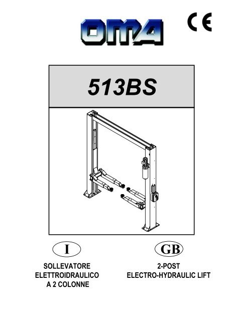
513BS<br />
I<br />
SOLLEVATORE<br />
ELETTROIDRAULICO<br />
A 2 COLONNE<br />
GB<br />
2-POST<br />
ELECTRO-HYDRAULIC LIFT
Manuale di istruzioni per l’uso e la manutenzione<br />
del<br />
SOLLEVATORE ELETTROIDRAULICO<br />
PER VEICOLI<br />
Matricola N°<br />
Anno di costruzione<br />
Modello 513BS<br />
Instructions and maintenance manual for<br />
Serial N°<br />
ELECTROHYDRAULIC LIFT<br />
FOR VEHICLES<br />
Year of manufacture<br />
Model 513BS<br />
COSTRUTTORE:<br />
OMA S.p.A.<br />
Sede centrale: Via dell’Artigianato, 64<br />
36045 LONIGO (VI) - ITALY<br />
Telefono ++ / +444 / 436190<br />
Telefax ++ / +444 / 436208<br />
MANUFACTURER:<br />
OMA S.p.A.<br />
Head office: Via dell’Artigianato, 64<br />
36045 LONIGO (VI) - ITALY<br />
Telefono ++ / +444 / 436190<br />
Telefax ++ / +444 / 436208<br />
3° Emissione - 10 Aprile 1996<br />
3st Edition - April 10, 1996<br />
CENTRO DI ASSISTENZA<br />
AUTORIZZATO:<br />
AUTHORISED<br />
SERVICE CENTER:<br />
Rev.11 .......................................29/01/2009<br />
3
Indice<br />
Imballaggio, trasporto<br />
e stoccaggio Pag. 3<br />
Contents<br />
Packing, transport and storage<br />
Page 3<br />
Introduzione Pag. 4<br />
Introduction Page 4<br />
Cap.1<br />
Descrizione della<br />
macchina Pag. 6<br />
Chapter 1<br />
Description<br />
of the machine Page 6<br />
Cap.2 Specifiche tecniche Pag. 8<br />
Chapter 2<br />
Technical<br />
specifications Page 8<br />
Cap.3 Sicurezza Pag.13<br />
Cap.4 Installazione Pag.20<br />
Chapter 3 Safety Page 13<br />
Chapter 4 Installation Page 20<br />
Cap.5 Funzionamento ed uso Pag.32<br />
Chapter 5<br />
Operating principles<br />
and use Page 32<br />
Cap.6 Manutenzione Pag.33<br />
Cap.7 Inconvenienti e rimedi Pag.36<br />
Chapter 6 Maintenance Page 33<br />
Chapter 7 Troubleshooting Page 36<br />
Appendice A<br />
Informazioni<br />
particolari<br />
Pag.37<br />
Appendix A Special notes Page 37<br />
Appendice B Parti di ricambio Pag.37<br />
Appendix B Spare parts Page 37<br />
3
IMBALLAGGIO, TRASPORTO E<br />
STOCCAGGIO<br />
LE OPERAZIONI DI IMBALLAGGIO, SOLLEVAMENTO, MOVI-<br />
MENTAZIONE, TRASPORTO E DISIMBALLO DEVONO ESSE-<br />
RE AFFIDATE ESCLUSIVAMENTE A PERSONALE CHE SIA<br />
ESPERTO IN TALI OPERAZIONI E CHE CONOSCA BENE IL<br />
SOLLEVATORE ED IL PRESENTE MANUALE<br />
IMBALLAGGIO<br />
Il <strong>sollevatore</strong> viene spedito smontato nei seguenti pezzi:<br />
Peso di un pezzo (Kg)<br />
1 Colonna lato comando completa di<br />
carrello, cilindro idraulico e quadro elettrico: Kg 285<br />
1 Colonna lato servizio completa di carrello<br />
e cilindro idraulico: Kg 280<br />
1 Trave superiore completa di tubo idraulico<br />
II° stadio e barra fine corsa: Kg 50<br />
4 Bracci completi di prolunga e piattello: Kg 55<br />
1 Centralina completa di motore e supporto: Kg 30<br />
1 Scatola di accessori e viteria: Kg 25<br />
1 Scatola contenente 4 kit bloccabracci: Kg 10<br />
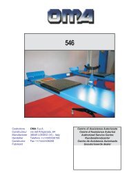
Il <strong>sollevatore</strong> viene inviato in una gabbia di legno (Figura 1) del<br />
peso medio di circa 980 Kg.<br />
PACKING, TRANSPORT AND<br />
STORAGE<br />
ALL PACKING, LIFTING, HANDLING, TRANSPORT AND<br />
UNPACKING OPERATIONS ARE TO BE PERFORMED EXCLU-<br />
SIVELY BY EXPERT PERSONNEL WITH KNOWLEDGE OF THE<br />
LIFT AND THE CONTENTS OF THIS MANUAL<br />
PACKING<br />
The <strong>lift</strong> is shipped disassembled into the following parts:<br />
Weight (Kg)<br />
1 Complete command <strong>post</strong>, complete with carriage, <strong>hydraulic</strong><br />
cylinder and control panel<br />
285 kg<br />
1 Commands side <strong>post</strong> with carriage and <strong>hydraulic</strong><br />
cylinder<br />
280 kg<br />
1 Upper beam complete with <strong>hydraulic</strong> horizontal<br />
pipe and end-of-stroke-bar<br />
50 kg<br />
4 Arms complete with extension and plate 55 kg<br />
1 Power unit complete with motor and support 30 kg<br />
1 Accessory package, nuts and bolts 25 kg<br />
1 Box containing 4 arm-locking kits 10 kg<br />
The <strong>lift</strong> is dispatched in a wooden crate (Fig.1), weighing approx.<br />
980 kg.<br />
SOLLEVAMENTO E MOVIMENTAZIONE<br />
Le gabbie in legno possono essere sollevate e s<strong>post</strong>ate sia con<br />
carrelli elevatori (fig.1) che con gru o carriponte (fig.2). Nel caso di<br />
movimentazione con gru o carriponte, le gabbie devono essere<br />
sempre imbragate con minimo 2 fasce.<br />
LIFTING AND HANDLING<br />
The wooden crates may be <strong>lift</strong>ed and moved with a <strong>lift</strong> truck (Fig.1)<br />
crane or bridge crane (Fig.2). If either of the latter two are used,<br />
crates must be harnessed with at least 2 slings.<br />
980<br />
Fig.1<br />
I mezzi scelti devono essere idonei al sollevamento e allo s<strong>post</strong>amento<br />
in sicurezza, tenendo conto di dimensioni, peso, baricentro,<br />
sporgenze e parti delicate da non danneggiare.<br />
STOCCAGGIO<br />
Gli imballi devono sempre essere conservati in luoghi coperti e protetti,<br />
a temperature comprese fra -10°C e +40°C. e non devono essere<br />
es<strong>post</strong>i ai raggi diretti del sole.<br />
IMPILAMENTO DEI PACCHI<br />
Il tipo di imballo previsto prevede la possibilità di impilare in magazzino<br />
fino ad 8 gabbie una sull’altra, purchè vengano correttamente<br />
dis<strong>post</strong>e ed assicurate contro la caduta.<br />
Nei cassoni dei camion o nei containers si possono impilare fino a<br />
3 gabbie, purchè vengano reggiate bene ed assicurate contro<br />
la caduta.<br />
Fig.2<br />
The equipment chosen must be suitable for safe <strong>lift</strong>ing and<br />
moving, bearing in mind the dimensions and weight.<br />
STORAGE<br />
Packed machinery must always be kept in a covered, protected<br />
place, at a temperature between -10° and +40°, and must not be<br />
exposed to direct sunlight.<br />
CRATE STACKING<br />
The type of packing allows the possibility of stacking up to 8<br />
crates.<br />
Up to 3 crates may be stacked one upon the other on lorries or in<br />
containers if properly positioned and provided they are restrained<br />
to prevent falling.<br />
4
APERTURA DEGLI IMBALLI<br />
All’arrivo verificare che la macchina non abbia subito danni durante<br />
il trasporto e che ci siano tutti i pezzi indicati nella lista di spedizione.<br />
Le gabbie devono essere aperte adottando tutte le precauzioni per<br />
evitare danni alle macchine e ai loro componenti (evitare cadute di<br />
pezzi dalla gabbia durante l’apertura).<br />
ELIMINAZIONE DELL’IMBALLO<br />
Il legno della gabbia può essere riutilizzato o riciclato.<br />
OPENING THE CRATES<br />
When the crates arrive, check that the machine has not been<br />
damaged during transport and that all parts listed are present.<br />
The crates must be opened using all possible precautionary<br />
measures to avoid damaging the machine or its parts. Make sure<br />
that parts do not fall from the crate during opening.<br />
DISPOSAL OF CRATES<br />
The wood of the crates may be re-used or recycled.<br />
INTRODUZIONE<br />
ATTENZIONE<br />
Questo manuale è stato scritto per il personale di officina addetto<br />
all’uso del <strong>sollevatore</strong> (operatore) e per il tecnico addetto<br />
alla manutenzione ordinaria (manutentore) pertanto, prima<br />
di effettuare qualsiasi operazione sul <strong>sollevatore</strong> e/o sul suo<br />
imballaggio, occorre leggere attentamente tutto il manuale,<br />
poichè esso contiene informazioni importanti per:<br />
- LA SICUREZZA DELLE PERSONE addette all’uso ed alla manutenzione<br />
ordinaria,<br />
- LA SICUREZZA DEL SOLLEVATORE,<br />
- LA SICUREZZA DEI VEICOLI SOLLEVATI.<br />
INTRODUCTION<br />
WARNING<br />
This manual has been prepared for workshop personnel<br />
expert in the use of the <strong>lift</strong> (operator) and technicians<br />
responsible for routine maintenance (maintenance fitter); read<br />
the manual before carrying out any operation with the <strong>lift</strong><br />
and/or the packing. This manual contains important<br />
information regarding:<br />
THE PERSONAL SAFETY of operators and maintenance workers,<br />
LIFT SAFETY,<br />
THE SAFETY OF LIFTED VEHICLES<br />
CONSERVAZIONE DEL MANUALE<br />
Il manuale è parte integrante del <strong>sollevatore</strong> e deve sempre accompagnarlo,<br />
anche in caso di vendita.<br />
Esso deve sempre essere conservato in vicinanza del <strong>sollevatore</strong>,<br />
in luogo facilmente accessibile.<br />
L’operatore ed il manutentore devono poterlo reperire e consultare<br />
rapidamente in qualsiasi momento.<br />
SI RACCOMANDA, IN PARTICOLARE, UNA LETTURA ATTENTA<br />
E RIPETUTA DEL CAPITOLO 3, CHE CONTIENE IMPORTANTI<br />
INFORMAZIONI E AVVISI RELATIVI ALLA SICUREZZA.<br />
CONSERVING THE MANUAL<br />
The manual is an integral part of the <strong>lift</strong> , which it should<br />
always accompany , even if the unit is sold.<br />
The manual must be kept in the vicinity of the <strong>lift</strong>, in an easily<br />
accessible place.<br />
The operator and maintenance staff must be able to locate and<br />
consult the manual quickly and at any time.<br />
ATTENTIVE AND REPEATED READING OF CHAPTER 3,<br />
WHICH CONTAINS IMPORTANT INFORMATION AND SAFETY<br />
WARNINGS, IS PARTICULARLY RECOMMENDED.<br />
Il <strong>sollevatore</strong> è stato progettato e costruito rispettando quanto segue:<br />
Lift rack has been designed and built in compliance with the following:<br />
LEGGI:<br />
Direttive europee: 98/37/CE-2004/108/CE-2006/95/CE<br />
NORME TECNICHE:<br />
Norme europee: EN 1493/ EN 292-1/ EN 292-2<br />
IMPIANTO ELETTRICO:<br />
UNI EN 60204, CEI 64/8<br />
LAWS:<br />
European directives: 98/37/CE-2004/108/CE-2006/95/CE<br />
TECHNICAL STANDARDS:<br />
European standards: EN 1493/ EN 292-1/ EN 292-2<br />
ELECTRICAL SYSTEM:<br />
UNI EN 60204, CEI 64/8<br />
5
Il sollevamento, il trasporto, il disimballo, il montaggio, l’installazione<br />
e la messa in servizio, la taratura e le registrazioni iniziali, la<br />
manutenzione STRAORDINARIA, la riparazione, la revisione, lo<br />
s<strong>post</strong>amento e lo smantellamento del <strong>sollevatore</strong> devono essere<br />
eseguiti dai tecnici specializzati dei RIVENDITORI AUTORIZZATI<br />
o dei CENTRI ASSISTENZA AUTORIZZATI dal Costruttore (vedere<br />
centro assistenza autorizzato indicato nel frontespizio):<br />
Il costruttore non risponde di alcun danno a persone, veicoli<br />
od oggetti causati dagli interventi sopracitati se effettuati da<br />
personale non autorizzato o da un uso improprio o non consentito<br />
del <strong>sollevatore</strong>.<br />
Per tutte queste attività vengono indicati, nel presente manuale,<br />
soltanto gli aspetti (operativi e di sicurezza) che possono essere<br />
utili anche all’operatore ed al manutentore per comprendere meglio<br />
la struttura ed il funzionamento del <strong>sollevatore</strong> e per un suo migliore<br />
utilizzo.<br />
Per comprendere il linguaggio adottato nel presente manuale, l’operatore<br />
deve possedere esperienza specifica nelle attività di officina,<br />
di assistenza, manutenzione e riparazione dei veicoli nonchè la<br />
capacità di interpretare correttamente i disegni e le descrizioni riportate<br />
nel manuale e la conoscenza delle norme antinfortunistiche<br />
generali e specifiche vigenti nel paese in cui viene installato il <strong>sollevatore</strong>.<br />
Gli stessi criteri valgono per la scelta del tecnico manutentore che<br />
dovrà, inoltre, possedere le conoscenze tecniche specifiche e specialistiche<br />
(meccaniche, elettriche) necessarie per effettuare in sicurezza<br />
gli interventi previsti nel manuale.<br />
The <strong>lift</strong>ing, transport, unpacking, assembling, installation, starting<br />
up, initial adjustment and testing, EXTRAORDINARY<br />
maintenance, repair, overhauls, transport and dismantling of the <strong>lift</strong><br />
must be performed by specialised personnel from the LICENSED<br />
DEALER or a SERVICE CENTRE authorised by the<br />
manufacturer (see authorised dealer on frontispiece).<br />
The manufacturer declines all responsibility for injury to persons<br />
or damage to vehicles or objects when any of the above<br />
mentioned operations has been performed by unauthorised<br />
personnel or when the rack has been subject to improper<br />
use.<br />
This manual indicates only the operative and safety aspects that<br />
may prove useful to the operator and maintenance worker, in<br />
better understanding the structure and operation of the <strong>lift</strong> and for<br />
best use .<br />
In order to understand the terminology used in this manual, the<br />
operator must have specific experience in workshop, service,<br />
maintenance and repair activities, the ability to interpret correctly<br />
the drawings and descriptions contained in the manual and be<br />
acquainted with the general and specific safety rules relevant to<br />
the country in which the machine has been installed.<br />
The same applies to the maintenance fitter, who must also<br />
possess specific and specialised knowledge (mechanical,<br />
engineering) needed to perform the operations described in the<br />
manual in complete safety.<br />
Nel testo del manuale troverete spesso le diciture “operatore” e<br />
“manutentore” il cui significato è il seguente:<br />
OPERATORE: persona addetta all’uso del <strong>sollevatore</strong>.<br />
MANUTENTORE: persona addetta alla manutenzione ordinaria del<br />
<strong>sollevatore</strong>.<br />
The words “operator” and “maintenance fitter” used in this<br />
manual are construed as follows:<br />
OPERATOR: person authorised to use the <strong>lift</strong><br />
MAINTENANCE FITTER: person authorised for routine<br />
maintenance of the <strong>lift</strong>.<br />
6
CAP.1. DESCRIZIONE DELLA<br />
MACCHINA<br />
CHAPTER 1<br />
THE MACHINE<br />
DESCRIPTION OF<br />
Il <strong>sollevatore</strong> <strong>elettroidraulico</strong> a 2 <strong>colonne</strong> è fisso, cioè ancorato al<br />
suolo ed è progettato e costruito per il sollevamento e lo stazionamento<br />
in quota di autoveicoli e furgoni.<br />
Il <strong>sollevatore</strong> è com<strong>post</strong>o, principalmente da :<br />
gruppo struttura fissa (<strong>colonne</strong> e trave superiore)<br />
gruppi mobili ( carrelli + bracci )<br />
gruppi di sollevamento (2 cilindri idraulici + centralina);<br />
quadro comando<br />
sicurezze.<br />
Nelle figure 3 e 4 sono indicate le varie parti che compongono il<br />
<strong>sollevatore</strong> e le zone di lavoro consentite e riservate al personale<br />
addetto, attorno al <strong>sollevatore</strong> stesso.<br />
Lato comando: è il lato del <strong>sollevatore</strong> che comprende la zona riservata<br />
all’operatore in cui si accede al quadro comandi<br />
Lato servizio: è il lato op<strong>post</strong>o a quello comando.<br />
Lato anteriore: è il lato braccio corto.<br />
Lato <strong>post</strong>eriore: è il lato braccio lungo.<br />
The 2-<strong>post</strong> <strong>electro</strong>-<strong>hydraulic</strong> <strong>lift</strong> is a fixed installation. This means<br />
that it is anchored to the ground and designed and built for <strong>lift</strong>ing<br />
and positioning automobiles and vans at a certain height off the<br />
ground.<br />
The <strong>lift</strong> consists of the following main parts:<br />
fixed structure (<strong>post</strong>s + upper beam);<br />
mobile units (carriage + arms);<br />
<strong>lift</strong> units (2 <strong>hydraulic</strong> cylinders + power unit);<br />
control box;<br />
safety devices.<br />
Figures 3 and 4 illustrate the various parts of the <strong>lift</strong> and the work<br />
areas reserved for use by operators around the <strong>lift</strong>.<br />
Command side: this side of the <strong>lift</strong> includes the area reserved for<br />
the operator to access the control box.<br />
Service side: this is the opposite side to the command side.<br />
Front side: the side with the short arm.<br />
Rear side: the side with the long arm.<br />
Lato servizio<br />
Service side<br />
Lato <strong>post</strong>eriore<br />
Rear side<br />
Lato comando<br />
Command side<br />
Lato anteriore<br />
Front side<br />
Fig.3<br />
GRUPPO STRUTTURA FISSA (Vedere Fig.4)<br />
E’ costituito da :<br />
2 Colonne, una lato comando (1) e una lato servizio (2), in lamiera<br />
di acciaio piegata, alla cui base è saldata una piastra con<br />
fori per il fissaggio al pavimento mediante tasselli di ancoraggio.<br />
All’interno di ogni colonna si trovano i gruppi mobili di sollevamento<br />
dell’automezzo.<br />
Alla colonna comando sono fissati il quadro elettrico di azionamento<br />
e la centralina idraulica.<br />
FIXED STRUCTURE (Fig.4)<br />
This structure consists of:<br />
2 Posts, (service and command side <strong>post</strong>) built with bent steel<br />
plate. The base is welded to a drilled<br />
plate to be anchored to the floor. The electric control box and the<br />
<strong>hydraulic</strong> power unit are attached to the command <strong>post</strong>.<br />
Inside each <strong>post</strong> are the moving parts to <strong>lift</strong> the vehicles.<br />
The control panel and the <strong>hydraulic</strong> unit are fixed to the command<br />
<strong>post</strong>.<br />
Una trave superiore (3) in lamiera piegata che, mediante bullonatura,collega<br />
le <strong>colonne</strong> nella loro estremità superiore.<br />
An upper beam (3) built with bent steel plate, connecting the upper<br />
<strong>post</strong>s with bolts.<br />
10<br />
10<br />
9<br />
2<br />
3<br />
1<br />
9<br />
8<br />
8<br />
4<br />
6 7<br />
5<br />
4<br />
10 10<br />
Fig.4<br />
7
GRUPPI MOBILI (Vedere Fig.4)<br />
Ciascuno è costituito da :<br />
Un carrello (4) in lamiera di acciaio saldata, collegato nella parte<br />
superiore ad un cilindro idraulico e nella parte inferiore, mediante<br />
perni, ai bracci di sollevamento.<br />
Il carrello scorre lungo la colonna, guidato, all’ interno di essa, da<br />
pattini in materiale plastico.<br />
Due bracci telescopici di cui uno lungo (5) e uno corto (6), costruiti<br />
in tubolare di acciaio, recanti ad una estremità il piattello<br />
regolabile in altezza (7) per la presa della macchina e dalla parte<br />
op<strong>post</strong>a gli attacchi con il foro di collegamento con il carrello.<br />
GRUPPO SOLLEVAMENTO (Vedere Fig.4)<br />
E’ costituito da:<br />
2 cilindri idraulici (8), per il sollevamento dei carrelli, ancorati<br />
alle piastre di base delle <strong>colonne</strong>.<br />
1 centralina idraulica (vedi fig.5), <strong>post</strong>a sulla colonna comando,<br />
per l’ azionamento dei cilindri.<br />
CENTRALINA IDRAULICA (Fig.5)<br />
La centralina é com<strong>post</strong>a da:<br />
Un motore elettrico di comando (1).<br />
Una pompa idraulica ad ingranaggi (2).<br />
Un’ elettrovalvola di discesa (3) dotata di un dispositivo di scarico<br />
manuale dell’ olio (vedi cap. Uso e Manutenzione).<br />
Una valvola di massima pressione (4).<br />
Un serbatoio olio (5).<br />
Un tubo flessibile (6) di mandata (e recupero) olio al circuito di<br />
distribuzione ai cilindri.<br />
N.B: il tubo di mandata olio può trovarsi in pressione.<br />
QUADRO DI COMANDO (Fig.6)<br />
Sul pannello del quadro elettrico di comando sono installati :<br />
L’interrutore generale (QS).<br />
Il pulsante di salita (SB1).<br />
Il pulsante di stazionamento (SB3).<br />
Il pulsante di discesa (SB2).<br />
MOVING UNITS (see fig.4)<br />
Each unit consists of:<br />
one carriage (4) built with welded steel plate, connected at the<br />
top to a <strong>hydraulic</strong> cylinder, and at the bottom, to the <strong>lift</strong> arms by<br />
means of pins.<br />
The carriage moves along the <strong>post</strong>, guided by plastic sliding pads,<br />
located inside the <strong>post</strong> itself.<br />
Two telescopic arms, one long (5) and one short (6), built with<br />
tubular steel with a pad (7) at each end that can be height<br />
adjusted to hold the car and on the opposite side the carriage<br />
connection hole.<br />
LIFT UNIT(see fig.4)<br />
it consists of:<br />
2 <strong>hydraulic</strong> cylinders (8), to <strong>lift</strong> the carriages anchored to the <strong>post</strong><br />
basis pads.<br />
1 <strong>hydraulic</strong> unit (see. fig. 5), on the command side, to set the<br />
cylinders run.<br />
HYDRAULIC POWER UNIT (Fig.5)<br />
The <strong>hydraulic</strong> power unit consists of:<br />
an electric motor (1),<br />
a geared <strong>hydraulic</strong> pump (2)<br />
descent <strong>electro</strong>-valve (3) equipped with a manual oil drain valve<br />
(see the Use and Maintenance chapter),<br />
a maximum pressure valve (4),<br />
oil tank (5)<br />
an oil delivery and return flexible pipe (6) to the cylinders feeding<br />
circuit<br />
Note: The oil delivery pipe may be under pressure.<br />
CONTROL BOX (Fig.6)<br />
The panel that houses the electric control box contains the following:<br />
Main switch (QS)<br />
Rise push button (SB1)<br />
Parking push button (SB3)<br />
Descent push button (SB2)<br />
1<br />
4<br />
6<br />
QS<br />
SB1<br />
3<br />
2<br />
SB3<br />
5<br />
SB2<br />
Fig.5 Centralina idraulica<br />
Hydraulic power unit<br />
Fig.6<br />
Quadro comando<br />
Control Panel<br />
SICUREZZE<br />
Le sicurezze sono costituite da :<br />
Un dispositivo di sicurezza meccanica per il carrello.<br />
Un sistema di bloccaggio bracci.<br />
Un dispositivo di sincronismo per la corsa dei carrelli costituito<br />
da un sistema di 2 funi (rif.9 Fig.4) e 6 carrucole di rinvio (rif.10<br />
Fig.4).<br />
Due finecorsa di estremità colonna.<br />
Le sicurezze elettriche<br />
Le sicurezze sull’ impianto idraulico.<br />
Un sensore per la differenza di livello fra i carrelli e l’allentamento<br />
e/o la rottura delle funi di sincronismo.<br />
Queste sicurezze saranno sviluppate in maggior dettaglio nei capitoli<br />
seguenti.<br />
SAFETY DEVICES<br />
The safety devices include:<br />
Mechanical safety device for carriage.<br />
Arms locking system.<br />
A synchronous device to control the carriages movement. The<br />
system consists of 2 cables (ref. 9, fig.4) and 4 return pulleys<br />
(ref.10, fig.4)<br />
2 <strong>post</strong> end limit switches<br />
General electric safety devices.<br />
General <strong>hydraulic</strong> safety devices.<br />
A sensor for the level difference between the carriage and the<br />
synchronized cables loosening and/or breaking.<br />
These safety devices will be described in further detail in the following<br />
chapters.<br />
8
CAP.2<br />
SPECIFICHE TECNICHE<br />
PORTATA: ................................................4000 Kg (39240 N)<br />
Alt. max. sollevamento auto ......................1950 mm<br />
Alt. min. supporti sollevamento ................. 125 mm<br />
Larg. libera tra le <strong>colonne</strong> .........................2800 mm<br />
Larg. totale ................................................3370 mm<br />
Larg. laterale piastre di base..................... 620 mm<br />
Lung. massima braccio ...........................1405 mm<br />
Lung. minima braccio ............................... 725 mm<br />
Tempo di salita ......................................... 35 sec<br />
Tempo di discesa ...................................... 35 sec<br />
Peso totale del <strong>sollevatore</strong> ........................circa 900 Kg<br />
Rumorosità................................................
POMPA della centralina idraulica:<br />
MOTORE<br />
Trifase<br />
Tipo 20<br />
Modello<br />
10A7,4X348N<br />
Cilindrata<br />
7,4 cm3/g<br />
Taratura valvola di massima<br />
160 bar<br />
Hydraulic unit PUMP<br />
MOTOR<br />
3-ph.<br />
Type 20<br />
Model<br />
10A7,4X348N<br />
Size<br />
7,4 cm3/g<br />
Relief valve set-up<br />
160 bar<br />
OLIO<br />
Il serbatoio dell’ olio contiene olio idraulico a base minerale secondo<br />
la normativa ISO/DIN 6743/4 con grado di contaminazione non<br />
superiore alla classe 18/15 secondo la normativa ISO 4406 come<br />
IP HYDRUS OIL 32, SHELL TELLUS OIL T32 od equivalenti.<br />
OIL<br />
The oil reservoir contains <strong>hydraulic</strong> mineral oil in accordance with<br />
ISO/DIN 6743/4 with a level of contamination that does not exceed<br />
class 18/15 according to ISO 4406, for example IP HYDRUS OIL<br />
32; SHELL TELLUS OIL T32 or equivalent.<br />
SCHEMA OLEODINAMICO<br />
HYDRAULIC OIL DIAGRAM<br />
1<br />
9<br />
1 9<br />
2<br />
3<br />
4<br />
5<br />
7<br />
6<br />
8<br />
Schema oleodina-<br />
Fig.8<br />
mico<br />
10<br />
Fig.8<br />
Oleodynamic<br />
scheme<br />
Rif.to<br />
Descrizione<br />
1 Cilindri operatori a semplice effetto<br />
2 Valvola di regolazione flusso<br />
3 Elettrovalvola di scarico<br />
4 Valvola di non ritorno<br />
5 Valvola di massima pressione e scarico<br />
6 Pompa<br />
7 Motore<br />
8 Filtro<br />
9 Valvole di blocco<br />
10 Serbatoio<br />
Ref.<br />
Description<br />
1 Operating cylinder with simple effect<br />
2 Flow control valve<br />
3 Drain <strong>electro</strong>-valve<br />
4 Check valve<br />
5 Maximum pressure drain valve<br />
6 Pump<br />
7 Motor<br />
8 Filter<br />
9 Lock valve<br />
10 Tank<br />
10
SCHEMA ELETTRICO TRIFASE<br />
THREE-PHASE WIRING DIAGRAM<br />
Fig.9<br />
Rif.<br />
Descrizione Description Marca<br />
Articolo<br />
Ref.<br />
Brand<br />
Article<br />
Q.ty<br />
C1-C2 ELM1-ELM2 Elettromagnete Electromagnet PR4TS-24DC/APC80 F6 SB 2<br />
C3 ELV Elettrovalvola Electro-valve OIL SISTEM 24VAC 50/60Hz ED100% 1<br />
FU1 F1 Portafusibili Fuse carrier WEBER PCH10x38 + CH10x38 2<br />
PTC F3 Limitatore di temperatura Temperature limiter Integrato nel motore / Integrate in the motor 1<br />
QM1 FC1 Microinterruttore sensore fune Cable sensor microswitch PIZZATO FR654 1<br />
QM5 FC2 Fine corsa salita Ascent limit switch PIZZATO FR654 1<br />
QM11 QM11 Fine corsa discesa Lowering limit switch PIZZATO FR754 1<br />
QS IG Interruttore generale Master switch SPRECHER LA2-16-1753+LFS2-N-6-175+LA2-12-C4+<br />
LA2-G2853+LA2-G3194<br />
KM1 K1 Teleruttore Contactor 24V 50/60Hz 1<br />
M M Motore elettrico Electric motor 230V/400V 50Hz 1<br />
SB1 P1 Pulsante salita Lifting push buttons 1NO 1<br />
SB2 P2 Pulsante discesa Lowering push buttons 3NO 1<br />
SB3 P3 Pulsante stazionamento Parking push button 2 NO 1<br />
FR2 Q1 Interruttore magnetotermico Automatic switch 10A TYPE C 1<br />
TM TR Trasformatore Transformer C.E. 230-400/24V 160A 50/60Hz 1<br />
SIR SIR Avvisatore acustico salvapiedi Siren 24V AC 1<br />
Morsetti utente User terminals CABUR CBD4 4mmq 7<br />
Morsetti linea Line terminals CABUR CBD2 2.5mmq 3<br />
Morsetti terra PE terminals CABUR TE4/D-TE4/0 4mmq 1<br />
Q.tà<br />
1<br />
11
TIPI DI VEICOLI SOLLEVABILI E INGOMBRI<br />
Il <strong>sollevatore</strong> si adatta praticamente a tutti i veicoli di peso non superiore<br />
a 4000 Kg e le cui dimensioni non eccedano quelle riportate<br />
di seguito.<br />
VEHICLE WEIGHT AND SIZE<br />
Lift rack can be adapted to virtually all vehicles not heavier than<br />
4000 kg, the dimensions of which do not exceed the following.<br />
DIMENSIONI MASSIME DEI VEICOLI DA SOLLEVARE<br />
La larghezza non deve eccedere i 2400 mm.<br />
Il passo tra gli assi non deve eccedere i 3000 mm.<br />
L’altezza minima da terra può interferire con le strutture del <strong>sollevatore</strong>.<br />
Fare attenzione soprattutto alle autovetture sportive.<br />
Eventuali carrozzati speciali possono essere sollevati tenendo però<br />
conto della portata del <strong>sollevatore</strong>.<br />
Anche la zona di rischio per le persone dovrà essere adeguata<br />
alle dimensioni speciali del veicolo.<br />
Gli schemi seguenti riportano i criteri per definire i limiti di impiego<br />
del <strong>sollevatore</strong>.<br />
MAXIMUM DIMENSIONS OF VEHICLES TO BE LIFTED<br />
Max. width: 2400 mm.<br />
Max. wheelbase: 3000 mm.<br />
The underbody of cars with low ground clearance may interfere<br />
with the structure of the <strong>lift</strong>. Pay particular attention in the case of<br />
low body sport cars.<br />
Always keep the capacity of the <strong>lift</strong> in mind in the case of vehicles<br />
with particular characteristics.<br />
The danger zone will be determined by the dimensions of the<br />
vehicle.<br />
The diagrams below include the criteria for defining the limits of<br />
use of the car rack.<br />
C<br />
B<br />
Fig.11<br />
A<br />
Misure minime e massime<br />
PER INGOMBRI MAGGIORI VERIFICARE IL CARICO MASSIMO<br />
E LO SBILANCIAMENTO DEL CARICO.<br />
Min.(mm) Max.(mm)<br />
A —- 2200<br />
B —- 3000<br />
C 150 —-<br />
Fig.11<br />
Minimum and maximum dimensions<br />
CHECK MAXIMUM LOAD CAPACITY AND LOAD<br />
DISTRIBUTION IN CASE OF LARGER VEHICLES.<br />
PESI MASSIMI DEI VEICOLI DA SOLLEVARE<br />
MAXIMUM WEIGHT OF THE VEHICLE TO BE LIFTed<br />
2660 1340 1340 2660<br />
MAX. 4000 Kg.!<br />
Fig.12<br />
Distribuzione dei pesi<br />
Fig.12<br />
Weight distribution<br />
12
CAP.3<br />
SICUREZZA<br />
E’ estremamente importante leggere questo capitolo attentamente<br />
ed in ogni sua parte poichè contiene importanti informazioni<br />
sui rischi che operatore e manutentore possono correre<br />
in caso di un uso errato del ponte <strong>sollevatore</strong>.<br />
Nel testo che segue troverete chiare spiegazioni su alcune situazioni<br />
di rischio o pericolo che si possono verificare durante<br />
l’uso e la manutenzione del <strong>sollevatore</strong>, sui dispositivi di sicurezza<br />
adottati e sul loro uso corretto, sui rischi residui e sui<br />
comportamenti da tenere (precauzioni generali e specifiche<br />
per eliminarli o neutralizzarli).<br />
ATTENZIONE:<br />
Il <strong>sollevatore</strong> è stato progettato e costruito per il<br />
sollevamento e lo stazionamento in quota dei veicoli<br />
in ambiente chiuso. Ogni altro uso non è consentito<br />
ed in particolare esso non è idoneo per<br />
operazioni di:<br />
- lavaggio e verniciatura;<br />
- ponteggio o sollevamento di persone;<br />
- pressa per schiacciare;<br />
- montacarichi;<br />
- CRIC per sollevare o cambiare ruote.<br />
Il costruttore non risponde di alcun danno a persone,<br />
veicoli od oggetti causati dall’uso improprio<br />
o non consentito dei sollevatori.<br />
É estremamente importante che in fase di salita o discesa<br />
l’operatore agisca soltanto dalla <strong>post</strong>azione di comando indicata in<br />
fig.13.<br />
É vietato a chiunque sostare entro la zona di rischio indicata in figura<br />
13.<br />
In fase di lavoro la presenza di persone sotto il veicolo è ammessa<br />
soltanto quando il veicolo è già sollevato.<br />
ATTENZIONE:<br />
LA PRESENZA DI PERSONE SOTTO IL VEICOLO<br />
SOLLEVATO E’ AMMESSA SOLTANTO QUANDO<br />
IL SOLLEVATORE E’ IN STAZIONAMENTO SUI<br />
MARTELLETTI DI SICUREZZA.<br />
NON UTILIZZARE LA MACCHINA SENZA LE PRO-<br />
TEZIONI O CON LE PROTEZIONI DISATTIVATE.<br />
IL MANCATO RISPETTO DI QUESTE NORME<br />
PUO’ RECARE<br />
GRAVI DANNI<br />
ALLE PERSONE,<br />
AL SOLLEVATORE<br />
ED AI VEICOLI<br />
SOLLEVATI.<br />
Zona di rischio<br />
Danger zone<br />
CHAPTER 3<br />
SAFETY<br />
It is vital to read this chapter of the manual carefully and from<br />
beginning to end as it contains important information<br />
regarding the risks that the operator or maintenance fitter may<br />
be exposed to in the eventuality that the <strong>lift</strong> is used incorrectly.<br />
The following text contains clear explanations regarding<br />
certain situations of risk or danger that may arise during the<br />
operation or maintenance of the <strong>lift</strong>, the safety devices<br />
installed and the correct use of such systems, residual risks<br />
and operative procedures to use (general and specific precautions<br />
to eliminate potential hazards).<br />
WARNING:<br />
Lift is designed and built to <strong>lift</strong> vehicles and hold<br />
them in the elevated position in a closed workshop.<br />
All other uses are unauthorised. In particular,<br />
the <strong>lift</strong> is not suitable for:<br />
- washing and respray work;<br />
- creating raised platforms or <strong>lift</strong>ing personnel;<br />
- use as a makeshift press for crushing purposes;<br />
- use as goods <strong>lift</strong>;<br />
- use as a jack for <strong>lift</strong>ing vehicles or changing<br />
wheels.<br />
The manufacturer disclaims all liability for injury<br />
to persons or damage to vehicles and other property<br />
caused by the incorrect and unauthorised<br />
use of the <strong>lift</strong>.<br />
During <strong>lift</strong> and descent movements, the operator must remain in<br />
the command station as defined in figure 13. The presence of<br />
persons inside the danger zone indicated in the same figure is<br />
strictly prohibited. The presence of persons beneath the vehicle<br />
during operations is permitted only when the vehicle is parked in<br />
the elevated position.<br />
WARNING:<br />
THE PRESENCE OF PERSONS BENEATH THE<br />
VEHICLE IS PERMITTED ONLY WHEN THE LIFT<br />
IS IN THE PARKING POSITION ON THE SAFETY<br />
WEDGES.<br />
DO NOT USE THE LIFT WITHOUT PROTECTION<br />
DEVICES OR WITH THE PROTECTION DEVICES<br />
INHIBITED.<br />
FAILURE TO<br />
COMPLY WITH<br />
THESE REGU-<br />
LATIONS CAN<br />
CAUSE SE-<br />
RIOUS INJURY<br />
TO PERSONS,<br />
AND IRREPARA-<br />
BLE DAMAGE<br />
TO THE LIFT<br />
AND THE VEHI-<br />
CLE BEING LIF-<br />
TED.<br />
Fig.13<br />
Zone di lavoro<br />
Zona operatore<br />
Operator’s area<br />
Fig.13<br />
Working areas<br />
13
PRECAUZIONI GENERALI<br />
L’operatore ed il manutentore sono tenuti al rispetto delle prescrizioni<br />
contenute in leggi e norme antinfortunistiche vigenti nel paese<br />
in cui è installato il <strong>sollevatore</strong>.<br />
Devono inoltre:<br />
operare sempre dalle <strong>post</strong>azioni di lavoro previste ed indicate<br />
nel manuale;<br />
non rimuovere nè disattivare i carter e le protezioni meccaniche,<br />
elettriche, o di altra natura;<br />
prestare attenzione agli avvisi di sicurezza riportati nelle targhette<br />
applicate sulla macchina e nel manuale.<br />
Nel testo del manuale gli avvisi di sicurezza saranno evidenziati<br />
nelle forme seguenti:<br />
PERICOLO: Indica un pericolo imminente che può causare danno<br />
alle persone (gravi lesioni o anche la morte).<br />
ATTENZIONE: Indica situazioni e/o comportamenti rischiosi che<br />
possono causare danni alle persone (lesioni più o meno gravi e/o<br />
anche la morte).<br />
CAUTELA: Indica situazioni e/o comportamenti rischiosi che possono<br />
causare danni di minore gravità alle persone e/o danni al <strong>sollevatore</strong>,<br />
al veicolo o ad altre cose.<br />
RISCHIO DI FOLGORAZIONE: è un particolare avviso di sicurezza<br />
che viene riportato sul <strong>sollevatore</strong>, tramite targhetta, in alcuni<br />
punti dove è particolarmente elevato il rischio di forti scosse elettriche.<br />
RISCHI E PROTEZIONI<br />
Vediamo ora quali rischi possono correre gli operatori o il manutentore<br />
in fase di stazionamento del veicolo sul <strong>sollevatore</strong> e quali protezioni<br />
sono state adottate dal costruttore per ridurre al minimo tali<br />
rischi:<br />
GENERAL PRECAUTIONS<br />
The operator and the maintenance fitter are required to observe<br />
the prescriptions of accident prevention legislation in force in the<br />
country of installation of the <strong>lift</strong>.<br />
Furthermore, the operator and maintenance fitter must:<br />
Always work in the scheduled working area as shown in the<br />
manual.<br />
never remove or deactivate the guards and mechanical,<br />
electrical, or other types of safety devices;<br />
read the safety notices affixed to the machine and the safety<br />
information in this manual.<br />
In the manual all safety notices are shown as follows:<br />
DANGER: Indicates imminent danger that can result in serious<br />
injury or death.<br />
WARNING: Indicates situations and/or types of manoeuvres that<br />
are unsafe and can cause injuries of various degrees or death.<br />
CAUTION: Indicates situations and/or types of manoeuvres that<br />
are unsafe and can cause minor injury to persons and/or damage<br />
the <strong>lift</strong>, the vehicle or other property.<br />
RISK OF ELECTRIC SHOCK: specific safety notice affixed to the<br />
<strong>lift</strong> in areas where the risk of electric shock is particularly high.<br />
RISKS AND PROTECTION DEVICES<br />
We shall now examine the risks to which operators or maintenance<br />
fitters may be exposed when the vehicle is immobilised in the<br />
raised position, together with the protection devices adopted by the<br />
manufacturer to reduce all such hazards to the minimum:<br />
SPOSTAMENTI LONGITUDINALI E LATERALI<br />
Gli s<strong>post</strong>amenti longitudinali sono i movimenti in avanti o all’indietro<br />
del carico.<br />
Gli s<strong>post</strong>amenti laterali sono i movimenti verso destra o verso sinistra<br />
che il veicolo può avere, specialmente durante la fase di salita<br />
sul <strong>sollevatore</strong>.<br />
Essi sono evitabili posizionando in maniera corretta il veicolo sui<br />
piattelli dei bracci, regolando alla stessa altezza (avvitando o svitando)<br />
i piattelli stessi.<br />
Lo s<strong>post</strong>amento dell’automezzo sui bracci, la regolazione dei<br />
bracci e dei piattelli deve essere fatto esclusivamente a bracci<br />
totalmente abbasssati e cioè con i piattelli liberi da qualunque<br />
contatto con il mezzo.<br />
LONGITUDINAL AND LATERAL MOVEMENT<br />
Longitudinal movement is considered the backward and forward<br />
shifting of the load.<br />
Lateral movement implies the shifting to the left or right of the<br />
vehicle, especially during the <strong>lift</strong>ing phase on the rack.<br />
These movements can be avoided by positioning the vehicle<br />
correctly on the arm disk support plates, which must be previously<br />
adjusted to the same height (by loosening or tightening) as the<br />
vehicle.<br />
Do not move the vehicle in relation to the arms or adjust arms<br />
and disk support plates until the arms have been totally<br />
lowered, i.e. the disk support plates must be free from all contact<br />
with the vehicle.<br />
Fig.14<br />
Rischio di caduta del veicolo<br />
Fig.14<br />
Risk of vehicle fall<br />
ATTENZIONE<br />
NON TENTARE DI SPOSTARE IL MEZZO QUAN-<br />
DO I PIATTELLI DI APPOGGIO SONO GIÀ A CON-<br />
TATTO CON QUESTO.<br />
WARNING<br />
DO NOT ATTEMPT TO MOVE THE VEHICLE<br />
WHEN IT IS RESTING ON THE DISK SUPPORT<br />
PLATES.<br />
14
É estremamente importante posizionare il mezzo sul <strong>sollevatore</strong> in<br />
modo da avere una corretta ripartizione dei pesi sui bracci (Fig.15)<br />
Per la sicurezza delle persone e dei mezzi è importante che:<br />
si rispetti la zona di rischio durante il sollevamento (Fig.13)<br />
il motore sia spento,la marcia innestata ed il freno a mano tirato.<br />
il veicolo sia posizionato in maniera corretta (Fig.15)<br />
vengano sollevati soltanto i veicoli ammessi (fig.11-12) senza<br />
superare portata ed ingombri previsti.<br />
It is very important to position the vehicle on the <strong>lift</strong> so that the<br />
weight is correctly distributed on the arms (fig.15). For persons and<br />
equipment safety, it is important that:<br />
<br />
people stay outside the danger zone while the vehicle raising<br />
(fig.13)<br />
the engine is off, the clutch engaged and the parking brake pulled.<br />
the vehicle is correctly positioned (fig.15)<br />
only authorised vehicles (fig.11-12) are raised without exceeding<br />
the rated capacity<br />
and overall dimensions.<br />
Fig.15 Veicolo<br />
caricato correttamente<br />
Fig.15<br />
Correctly loaded vehicle<br />
RISCHI IN FASE DI SOLLEVAMENTO DEL VEICOLO<br />
Contro i sovraccarichi in peso e contro eventuali rotture sono stati<br />
adottati i seguenti dispositivi di sicurezza:<br />
in caso di sovraccarico sul motore interviene il relè termico nel<br />
quadro elettrico.<br />
in caso di sovraccarico del <strong>sollevatore</strong> interviene la valvola di<br />
massima pressione (rif.1 Fig.16).<br />
nel caso dovesse verificarsi improvvisamente una grossa perdita<br />
nel circuito idraulico (es.: rottura di un tubo), intervengono le valvole<br />
di blocco <strong>post</strong>e nella parte inferiore dei cilindri (rif.1 Fig.17).<br />
nel caso dovesse verificarsi la rottura e/o l’allentamento delle<br />
funi di sincronismo interviene il sensore (rif.1 Fig. 17a) applicato<br />
sulla trave superiore che azione il microinterruttore di sicurezza<br />
funi e sicurezza salita (rif.2 Fig. 17a).<br />
RISKS WHILE THE VEHICLE IS BEING RAISED<br />
The following safety devices have been installed to protect against<br />
overweight conditions and equipment failure:<br />
the thermal relay in the electric box will trip if the motor is<br />
overloaded.<br />
the maximum pressure valve (1, fig.16), located on the <strong>hydraulic</strong><br />
oil power unit, will trip if the <strong>lift</strong> is overloaded.<br />
In case of a sudden, great leakage in the <strong>hydraulic</strong> circuit ( a<br />
broken pipe), the blocking valves, at the bottom of each cylinder,<br />
will trip (ref.1, fig.17).<br />
In case of a sudden, synchronized cables loosening and/or breaking,<br />
the sensor intervenes (ref.1 Fig. 17a) on the upper beam<br />
action the microswitch safety cables and safety <strong>lift</strong> (ref.2 Fig.<br />
17a).<br />
1<br />
1<br />
Fig.17<br />
Fig.16<br />
2<br />
1<br />
Fig. 17a<br />
15
in caso di avaria completa dei microinterruttori, i carrelli si fermerebbero<br />
pochi mm più in alto perché i cilindri idraulici andrebbero<br />
a fine corsa facendo intervenire la valvola di massima pressione<br />
sulla centralina.<br />
If the <strong>hydraulic</strong> cylinder breaks, the safety wedges will trip (ref.1,<br />
see.fig.18), located inside the <strong>post</strong>s (2). The wedges are pushed<br />
by the spring (3) and immediately stop the carriages (4) preventing<br />
their descent<br />
2<br />
3<br />
1 4<br />
1<br />
2<br />
CARRELLO IN FASE<br />
DI DISCESA<br />
DESCENDING<br />
CARRIAGE<br />
CARRELLO IN FASE<br />
ARRESTO O SALITA<br />
STOPPING OR RISING<br />
CARRIAGE<br />
Fig.18<br />
Fig.19<br />
nel caso vengano sollevati autoveicoli di altezza superiore a 1,5<br />
metri, la salita viene interrotta dalla “barra di finecorsa” (rif.1<br />
Fig.20) che, spinta dal veicolo, agisce sui microinterruttori.<br />
in caso di extra corsa della parte mobile, sono stati previsti due<br />
microinterruttori (rif.2 e 3 Fig.20) collegati in serie tra loro e montati<br />
nella parte superiore della colonna lato comando; essi sono<br />
azionati normalmente dall’ “azionatore” (rif.1 Fig. 19) montato sul<br />
carrello lato comando; nel caso che il primo microinterruttore<br />
non dovesse funzionare, il secondo interviene dopo circa 30 mm<br />
di corsa del carrello.<br />
in caso di rottura del cilindro idraulico intervengono automaticamente<br />
i martelletti di sicurezza (rif.1) (vedere Fig.18), <strong>post</strong>i all’ interno<br />
delle <strong>colonne</strong> (2), che, spinti dalla molla (3), arrestano immediatamente<br />
i carrelli (4) impedendone la discesa.<br />
When vehicles higher than 1.5m are <strong>lift</strong>ed, the rise is interrupted<br />
by the “end-stroke bar “(ref.1, fig.20), which, pushed by the<br />
vehicle, works on the limit switches.<br />
if the moving part exceeds its travel distance, on the upper part<br />
of the command <strong>post</strong> there are two limit switches (ref.2 and 3,<br />
fig.20) connected in series and are usually set working by the<br />
“actuator” (ref.1 fig.19) on the command side carriage. If the first<br />
limitswitch did not work, the second one would trip after 30 sec.<br />
of carriage run.<br />
in case of total breakdown of the limitswitches, the carriages will<br />
stop a few mm higher, because the <strong>hydraulic</strong> cylinders, come to<br />
endstroke, will cause the maximum pressure valve (on <strong>hydraulic</strong><br />
unit) to trip.<br />
3<br />
Fig.20<br />
1<br />
2<br />
16
RISCHI DIRETTI ALLE PERSONE<br />
In questo paragrafo verranno illustrati i rischi che operatore, manutentore<br />
e chi si trova nell’area di lavoro del <strong>sollevatore</strong>, possono<br />
correre a causa di un uso non corretto del <strong>sollevatore</strong> stesso.<br />
RISKS TO PERSONS<br />
This paragraph illustrates risks to which the operator, maintenance<br />
worker or any person near the operating area of the <strong>lift</strong> may be<br />
exposed in the case of improper use of equipment.<br />
RISCHIO DI SCHIACCIAMENTO<br />
DELL’OPERATORE<br />
dovuto ad una errata posizione dell’operatore<br />
addetto al quadro comandi.<br />
Durante la fase di discesa dei bracci<br />
e del veicolo l’ operatore non deve<br />
mai portarsi sotto le parti mobili in<br />
fase di discesa ma operare soltanto<br />
dalla zona comando (Fig.21).<br />
Fig.21<br />
Rischio di schiacciamento<br />
dell’operatore<br />
RISK OF CRUSHING<br />
(OPERATOR)<br />
Possible if the operator controlling<br />
the <strong>lift</strong> is not in the specified position<br />
at the command panel. When<br />
the platforms and vehicle are descending,<br />
the operator must never<br />
be partly or completely underneath<br />
the moving structure. During<br />
this phase the operator must<br />
remain in the command zone<br />
fig.21.<br />
Fig.21 Operator crushing risk<br />
RISCHIO DI SCHIACCIAMENTO DEL PERSONALE IN GENERE<br />
Durante la fase di discesa del <strong>sollevatore</strong> e del veicolo il personale<br />
non deve sostare in zone interessate<br />
dalle traiettorie di discesa (Fig.22).<br />
L’operatore deve manovrare solo<br />
dopo essersi accertato che nessuna<br />
persona sia in posizioni pericolose.<br />
RISK OF CRUSHING (PERSONNEL)<br />
When the platforms and vehicle are descending personnel are<br />
prohibited from entering the area<br />
beneath the moving parts of the<br />
<strong>lift</strong> (fig.22). The <strong>lift</strong> operator must<br />
not start the manoeuvre until it<br />
has been clearly established that<br />
there are no persons in potentially<br />
dangerous positions.<br />
Fig.22<br />
Rischio di schiacciamento<br />
del personale in genere<br />
Fig.22<br />
Generic people crushing risk<br />
RISCHIO DI URTO<br />
Dovuto alle parti del <strong>sollevatore</strong> o del veicolo posizionate ad altezza<br />
d’uomo.<br />
Quando, per ragioni di lavoro, il <strong>sollevatore</strong><br />
viene fermato a quote relativamente<br />
basse (inferiori a 1,75 m dal<br />
suolo) vi è il rischio di urtare contro le<br />
parti non evidenziate da particolari<br />
colorazioni (Fig.23).<br />
RISK OF IMPACT<br />
Caused by parts of the <strong>lift</strong> or the vehicle that are positioned at head<br />
height.<br />
When, due to operational reasons,<br />
the <strong>lift</strong> is immobilised at relatively<br />
low elevations (less than<br />
1.75 m from the ground) personnel<br />
must be careful to avoid impact<br />
with parts of the machine not<br />
marked with special hazard colouring<br />
(Fig.23).<br />
Fig.23<br />
Rischio di urto<br />
Fig.23 Impact risk<br />
RISCHIO DI SPOSTAMENTO DEL<br />
VEICOLO<br />
Dovuto ad operazioni da compiere e<br />
che generano spinte sul veicolo<br />
(Fig.24).<br />
Se il veicolo é di dimensioni o pesi ragguardevoli<br />
uno s<strong>post</strong>amento può rappresentare<br />
una situazione di sovraccarico<br />
o sbilanciamento non previsto pertanto<br />
evitare in maniera assoluta tali<br />
manovre.<br />
RISKS DUE TO VEHICLE<br />
MOVEMENT<br />
Movement may be caused during<br />
operations which involve force sufficient<br />
to move the vehicle (Fig.24).<br />
If the vehicle is of considerable dimensions<br />
or weight, movement<br />
may lead to overloading or unbalancing;<br />
all measures must be taken<br />
to avoid such an occurrence.<br />
Fig.24<br />
Rischio di s<strong>post</strong>amento del veicolo<br />
Fig.24<br />
Vehicle movement risk<br />
17
RISCHIO DI CADUTA DEL VEICOLO DAL SOLLEVATORE.<br />
Che può essere causato dal posizionamento non corretto del veicolo<br />
sui piattelli dei bracci, da un posizionamento<br />
non corretto del veicolo rispetto<br />
al <strong>sollevatore</strong> (Fig.25) o da dimensioni<br />
del veicolo non compatibili<br />
con lo stesso <strong>sollevatore</strong>.<br />
RISK OF VEHICLE FALLING FROM LIFT<br />
This risk could be caused by the incorrect positioning of the vehicle<br />
on the arm disk support plates<br />
(fig.25) or incorrect positioning of<br />
the arm disk support plates in relation<br />
to the <strong>lift</strong>.<br />
Fig.25<br />
Rischio di caduta del veicolo<br />
Fig.25<br />
Risk of vehicle fall<br />
E’ VIETATO SALIRE SUL VEICOLO E/O METTER-<br />
LO IN MOTO CON IL SOLLEVATORE INNALZATO<br />
(Fig.26).<br />
NEVER BOARD THE VEHICLE AND/OR TURN<br />
THE ENGINE ON WHEN LIFT IS RAISED (fig.26).<br />
Fig.26<br />
NON LASCIARE OGGETTI APPOGGIATI ALLE COLONNE O<br />
NELLA ZONA DI DISCESA DELLE PARTI MOBILI in quanto si<br />
può avere il blocco della discesa,o la caduta del veicolo<br />
(Fig.27).<br />
NEVER LEAN OBJECTS AGAINST THE POSTS OR LEAVE<br />
THEM IN THE AREA WHERE MOVING PARTS ARE LOWERED;<br />
this could hamper lowering or cause the vehicle to fall from<br />
the rack (fig.27).<br />
Fig.27<br />
RISCHIO DI SCIVOLAMENTO<br />
Dovuto a zone del pavimento sporche di lubrificanti (Fig.28).<br />
TENERE PULITA LA ZONA SOTTO E VICINA AL SOLLEVATO-<br />
RE pulendo le MACCHIE D’OLIO.<br />
Al fine di evitare il rischio di scivolamento utilizzare i mezzi individuali<br />
previsti (scarpe antinfortunistiche).<br />
SLIPPING<br />
This risk may arise due to spillage of lubricants in the surrounding<br />
area (fig.28).<br />
ALWAYS KEEP THE AREA SURROUNDING THE LIFT CLEAN<br />
by removing all OIL SPILLS.<br />
To avoid the risk of slipping, make use of the recommended personal<br />
protection (anti-slip footwear).<br />
Fig.28<br />
Rischio di scivolamento<br />
Fig.28<br />
Skidding risk<br />
18
RISCHIO DI FOLGORAZIONE<br />
Accanto a parti del <strong>sollevatore</strong> in cui si<br />
trovano fili elettrici evitate getti d’acqua,<br />
di vapore (da pulitrice a vapore), di solventi<br />
o vernici nella zona del <strong>sollevatore</strong><br />
ed in particolar modo nelle immediate<br />
vicinanze del quadro elettrico (Fig.29).<br />
RISK OF ELECTRIC SHOCK<br />
Risk of electric shock in areas of<br />
the <strong>lift</strong> housing electrical wiring.<br />
Do not use jets of water, steam<br />
(high pressure wash units), solvents<br />
or paint in the immediate vicinity<br />
of the <strong>lift</strong>, and take special<br />
care to keep such substances<br />
clear of the electrical command<br />
panel (fig.29).<br />
Fig.29<br />
Rischio di folgorazione<br />
Fig.29<br />
Electrocaution risk<br />
RISCHIO DA ILLUMINAZIONE NON IDONEA<br />
L’operatore ed il manutentore devono verificare che tutte le zone<br />
del <strong>sollevatore</strong> siano sempre illuminate in maniera uniforme ed in<br />
conformità a quanto previsto dalla normativa vigente nel luogo di<br />
installazione.<br />
RISCHIO DI ROTTURE DI COMPONENTI DURANTE IL<br />
FUNZIONAMENTO.<br />
Il costruttore ha utilizzato materiali e procedure progettuali e costruttive<br />
idonee all’uso previsto e atte a creare un’apparecchiatura<br />
affidabile e sicura ma è necessario rispettare l’uso per cui è stato<br />
progettato il <strong>sollevatore</strong> nonchè le frequenze delle ispezioni e delle<br />
manutenzioni consigliate nel capitolo 6 “MANUTENZIONE”.<br />
RISCHI PER USI NON CONSENTITI.<br />
Non é ammessa la presenza di persone<br />
sulle pedane nè durante il sollevamento<br />
nè quando il veicolo è gia’ sollevato<br />
(Fig.30).<br />
RISKS RELATED TO INAPPROPRIATE LIGHTING.<br />
The operator and the maintenance fitter must be able to assure<br />
that all the areas of the <strong>lift</strong> are properly and uniformly illuminated in<br />
compliance with the laws in force in the place of installation.<br />
RISK OF COMPONENT FAILURE DURING OPERATION.<br />
The manufacturer has used appropriate materials and construction<br />
techniques in relation to the specified use of the machine in order<br />
to manufacture a reliable and safe <strong>lift</strong>. Note however, that the <strong>lift</strong><br />
must be used in conformity with manufacturer’s prescriptions and<br />
the frequency of inspections and maintenance work recommended<br />
in chapter 6 “MAINTENANCE” must be observed.<br />
RISKS RELATED TO IMPROPER<br />
USE<br />
Persons are not permitted to stand<br />
or sit on the platforms during the<br />
<strong>lift</strong><br />
manoeuvre or when the vehicle is<br />
already <strong>lift</strong>ed (fig.30).<br />
Fig.30<br />
Ogni uso del <strong>sollevatore</strong>, diverso da quello per cui è stato progettato<br />
può creare incidenti, anche molto gravi, alle persone<br />
che stanno lavorando nelle immediate vicinanze.<br />
É pertanto estremamente importante attenersi scrupolosamente a<br />
tutte le regole riguardanti l’uso, la manutenzione e la sicurezza riportate<br />
in questo manuale.<br />
All uses of the <strong>lift</strong> other than the uses for which it was<br />
designed are liable to give rise to serious accidents involving<br />
the persons working in the immediate vicinity of the unit.<br />
It is therefore essential to adhere scrupulously to all regulations<br />
regarding use, maintenance and safety contained in this manual.<br />
Dati motore<br />
Motor data<br />
Portata<br />
Capacity<br />
Matricola<br />
Serial number<br />
Istruzioni d’uso<br />
Using instructions<br />
Fig.31<br />
avvisi di sicurezza e targhette applicati<br />
sulla macchina.<br />
Fig.31<br />
Safety notices and data plates affixed<br />
to the machine<br />
19
CAP.4<br />
INSTALLAZIONE<br />
CHAPTER 4<br />
INSTALLATION<br />
QUESTE OPERAZIONI SONO DI COMPETENZA<br />
ESCLUSIVA DEI TECNICI SPECIALIZZATI INCARI-<br />
CATI DAL COSTRUTTORE O DAI RIVENDITORI<br />
AUTORIZZATI .<br />
SE EFFETTUATE DA ALTRE PERSONE POSSO-<br />
NO CREARE SITUAZIONI DI PERICOLO E CAU-<br />
SARE GRAVI DANNI ALLE PERSONE E/O AL<br />
SOLLEVATORE.<br />
VERIFICA DEI REQUISITI PER L’INSTALLAZIONE<br />
Il <strong>sollevatore</strong> è costruito per l’impiego in locali chiusi e riparati. Il<br />
luogo prescelto non deve essere vicino a lavaggi, a <strong>post</strong>i di verniciatura,<br />
a depositi di solventi o vernici, a locali con lavorazioni che<br />
possono creare atmosfere esplosive.<br />
VERIFICA DI IDONEITÀ DELLE DIMENSIONI DEL LOCALE E<br />
DELLE DISTANZE DI SICUREZZA.<br />
Il <strong>sollevatore</strong> deve essere installato rispettando le distanze di sicurezza<br />
da muri,<strong>colonne</strong>, altre macchine, ecc... come indicate in Figura<br />
32 e secondo le eventuali prescrizioni della legislazione vigente<br />
nel luogo di installazione. Nel caso di officine con più sollevatori,<br />
la loro disposizione dovrà essere definita e dettagliata in<br />
base alle norme di lavoro e di sicurezza.<br />
Verificare in particolare:<br />
altezza: minimo 5000 mm; considerare l’altezza dei veicoli da<br />
sollevare tenendo conto che l’altezza max. dei bracci è di circa<br />
1930 mm e che la trave superiore é <strong>post</strong>a all’ altezza di circa<br />
3400 mm.<br />
distanza dai muri: minimo 700 mm,<br />
spazi per lavorare: minimo 800 mm, oltre le dimensioni del veicolo<br />
da sollevare.<br />
spazi per la POSTAZIONE DI COMANDO,<br />
spazi per la manutenzione, per accessi e vie di fuga in caso di<br />
emergenze.<br />
posizione relativa alle altre macchine,<br />
possibilità di realizzare l’allacciamento elettrico.<br />
Nel caso di officine con più<br />
sollevatori, la loro disposizione<br />
dovrà<br />
essere definita e dettagliata in<br />
base<br />
alle norme di lavoro e di sicurezza.<br />
THE FOLLOWING OPERATIONS MUST BE<br />
PERFORMED EXCLUSIVELY BY SPECIALISED<br />
TECHNICAL STAFF WITH AUTHORISATION<br />
FROM THE MANUFACTURER OR LICENSED<br />
DEALER. IF THESE OPERATIONS ARE PERFOR-<br />
MED BY OTHER PERSONS , SERIOUS<br />
PERSONAL INJURY AND/OR IRREPARABLE DA-<br />
MAGE TO THE LIFT UNIT MAY RESULT.<br />
INSTALLATION REQUISITE CHECKLIST<br />
The <strong>lift</strong> is designed for installation in enclosed areas suitably<br />
protected from the weather. The place of installation must be well<br />
clear of areas destined to washing or painting, and away from<br />
solvent or paint storage areas or areas where there is a risk of<br />
potentially explosive atmosphere.<br />
SUITABILITY OF THE DIMENSIONS OF THE PLACE OF<br />
INSTALLATION AND SAFETY CLEARANCES.<br />
The <strong>lift</strong> must be installed in observance of the clearances between<br />
walls, pillars, other machines, etc. indicated in Figure 32 and in<br />
compliance with any legislative requirements in the country of<br />
installation. If in a garage several hoists are installed, their emplacement<br />
has to be carried out according to the relevant labour safety<br />
rules.<br />
Check in particular:<br />
minimum height: 5000 mm inclusive of height of vehicle, maximum<br />
height of arms, (i.e. 1930 mm.), and upper beam height<br />
(i.e.3400mm)<br />
minimum distance from walls: 700 mm,<br />
minimum working area: 800 mm,<br />
area for COMMAND STATION,<br />
area for maintenance, access and emergency escape routes.<br />
position in relation to other machines,<br />
proximity to power supply for trouble-free hook-up.<br />
If in a garage several hoists are installed, their emplacement<br />
has to be carried out according to the relevant labour safety<br />
rules.<br />
Fig.32 Safety distances<br />
Fig.32<br />
Distanze di sicurezza<br />
ILLUMINAZIONE<br />
Tutte le zone della macchina devono essere illuminate in modo<br />
uniforme e sufficiente per garantire le operazioni di regolazione e<br />
manutenzione previste nel manuale, evitando zone d’ombra, riflessi,<br />
abbagliamento e affaticamento della vista.<br />
L’illuminazione deve essere realizzata in accordo con la normativa<br />
vigente nel luogo di installazione (a cura dell’installatore dell’impianto<br />
di illuminazione).<br />
LIGHTNIG<br />
All parts of the machine must be uniformly lit with sufficient light to<br />
assure that the adjustment and maintenance operations specified<br />
in the manual can be performed, and without areas of shadow, reflected<br />
light, glare and avoiding all situations that could give rise to<br />
eye fatigue.<br />
The lighting must be installed in accordance with the laws in force<br />
in the place of installation (responsibility lies with the lighting<br />
equipment fitter).<br />
20
PAVIMENTO<br />
Il <strong>sollevatore</strong> deve essere installato<br />
su platea orizzontale di spessore<br />
minimo 150 mm (100mm) realizzata<br />
in calcestruzzo dosato con resistenza<br />
min di 25 N/mm2.<br />
Il pavimento deve inoltre essere<br />
piano e ben livellato (10 mm di tolleranza<br />
sul livellamento).<br />
Nel caso di applicazioni particolari,<br />
interpellare il costruttore.<br />
Fig.33<br />
MONTAGGIO<br />
Spessore pavimento<br />
ATTENZIONE<br />
DURANTE IL MONTAGGIO NON É AMMESSO<br />
NESSUN ESTRANEO AI LAVORI<br />
Per effettuare l’ installazione del <strong>sollevatore</strong>,considerati i pesi<br />
dei vari componenti, é necessario provvedere ad un mezzo di<br />
sollevamento con le seguenti caratteristiche:<br />
Portata minima: 300 kg.<br />
Altezza massima di sollevamento: 4 m<br />
Prima di iniziare il montaggio verificare,con<br />
il Packing List, che nella gabbia<br />
sia contenuto tutto il materiale necessario.<br />
MONTAGGIO COLONNE<br />
1 - Prendere con il mezzo di sollevamento<br />
la colonna comando e, in posizione<br />
orizzontale, montare la centralina<br />
idraulica (priva di olio) (Rif.1 Fig.34) utilizzando<br />
le 4 viti TE M8x16 con relative<br />
rondelle già premontate nei fori allo scopo<br />
predis<strong>post</strong>i.<br />
2 - Montare il particolare appoggio trave<br />
(Rif. 2 Fig.34) utilizzando una vite TE<br />
M10x25 con dado esagonale e 2 rondelle<br />
piane; l’ altro appoggio (Rif.3 Fig.34)<br />
é premontato in quanto é utilizzato anche<br />
come supporto dei microinterruttori<br />
di finecorsa.<br />
1<br />
2<br />
WARNING<br />
FLOOR<br />
The <strong>lift</strong> must be installed on a<br />
horizontal concrete bed with a<br />
minimum thickness of 150mm<br />
(100mm) built and a resistance minimum<br />
25 N/mm2.<br />
The floor must also be flat and level<br />
(10 mm of tolerance for levelling).<br />
Consult the manufacturer with regard<br />
to special applications.<br />
Fig.33<br />
ASSEMBLING<br />
Floor thickness<br />
DURING INSTALLATION ONLY AUTHORISED<br />
PERSONNEL IS ALLOWED<br />
To assemble the <strong>lift</strong>, the weight of the various parts is to be<br />
considered, in order to provide a <strong>lift</strong>ing machine with the<br />
following caracteristics:<br />
Minimum capacity 300kg<br />
max. <strong>lift</strong>ing height 4 m<br />
Before starting to assemble the <strong>lift</strong>, check the crate contains all the<br />
needed material.<br />
3<br />
POSTS ASSEMBLING<br />
1 - With the <strong>lift</strong>ing machine take the command<br />
<strong>post</strong> and, in an horizontal position,<br />
assemble the <strong>hydraulic</strong> unit (without oil)<br />
(ref.1, fig.34) using the 4 HH screws<br />
M8x16 and washers, already set in the<br />
drills.<br />
2 - Mount the special beam-support<br />
(ref.2, fig.34) using a HH screw M10x25<br />
with hex. nut and flat washers; The other<br />
support (ref.3, fig.34) is already on the<br />
<strong>post</strong>, as it can also be used as limitswitch<br />
support.<br />
Fig.34<br />
Montaggio centralina eappoggio trave<br />
Fig. 34<br />
Power unit and beam support assembling<br />
21
3 - Sollevare in verticale la colonna comando e posizionarla nel<br />
punto di installazione prestabilito curando gli allineamenti col fabbricato.<br />
4 - Eseguire 6 fori sul pavimento, con punta elicoidale da calcestruzzo<br />
di diametro 24 mm per una profondità minima di 125 mm<br />
(Fig.35), usando la piastra di base come dima di foratura (Fig. 36).<br />
5 - Soffiare neI fori con aria compressa per rimuovere la polvere di<br />
trapanatura che ridurrebbe la tenuta di fissaggio, e inserire, completamente<br />
nel pavimento, 6 tasselli ad espansione tipo HILTI<br />
HSL-TZ M16/50, HSL-3 16/50, FISCHER FH24/25H o equivalenti.<br />
3 - Raise the command <strong>post</strong> up and place it in the set assembling<br />
point, paying attention to the machine position in referece to the<br />
building.<br />
4 - Make 6 drills on the basement with a helical concrete bit with a<br />
diameter of 24 mm to a depth of 125mm (fig.35). Use the basis pad<br />
as a drilling template. (fig.36).<br />
5 - Blow compressed air into the drill to remove the drilling dust,<br />
which could lessen the fixing tightness . Insert completely in the floor<br />
6 anchor bolts type HILTI HSL-TZ M16/50, HSL-3 16/500,<br />
FISCHER FH24/25H or similar.<br />
Fig.35<br />
1<br />
Fig.36<br />
INTERNO COLONNE<br />
POSTS DISTANCE<br />
Fig.37<br />
6 - Avvitare le viti dei tasselli, senza serrare a fondo, in modo da<br />
sorreggere la colonna (il serraggio con chiave dinamometrica deve<br />
essere effettuato dopo il montaggio completo della struttura).<br />
7 - Prendere la colonna lato servizio e montare i due particolari appoggio<br />
trave superiore (Rif.1Fig.37) utilizzando per ciascuno una<br />
vite TE M10x25 con dado esagonale e due rondelle piane.<br />
8 - Sollevare in verticale la colonna lato servizio e posizionarla alla<br />
distanza indicata in Fig.38 avendo cura di allinearne orizzontalmente<br />
le fiancate con quelle della colonna comando.<br />
9 - Ripetere le operazioni di cui ai punti 4-5-6 anche per la colonna<br />
lato servizio.<br />
Fig.38<br />
6 - Tighten the bolts screws, only as tight as needed to substain<br />
the <strong>post</strong>, (tighten with a torque wrench only after having assembled<br />
the complete structure.<br />
7 - Mount the two special “upper beam supports” (ref. 1, fig.37) on<br />
the service side <strong>post</strong>, using HH screws M10x25, Hex. nuts and flat<br />
washers.<br />
8 - Raise the command <strong>post</strong> up and place it at a distance as shown<br />
in fig.38, caring to set it perfectly parallel to the commands <strong>post</strong>.<br />
9 - Repeat the same operations described in n°4-5-6 for the service<br />
side <strong>post</strong>, too.<br />
ANCORAGGIO PER PAVIMENTI 100mm > 150mm<br />
MONTAGGIO SUPPOTO BASE COLONNA<br />
Coppia di serraggio 30 Nm.<br />
ANCHOR FOR FLOORS 100mm > 150mm<br />
COLUMN BASE SUPPORT<br />
Torque wrench 30 Nm.<br />
22
9 - Prendere la trave superiore (1) (Vedere Fig.39) e montare ad<br />
ognuna delle sue estremità: due puleggie (2), un distanziale lungo<br />
(3), due distanziali corti (4) e il perno (5).<br />
10 - Prendere il gruppo, imbragandolo con il mezzo di sollevamento,<br />
posizionarlo sugli appositi appoggi (Rif.1 Fig.40) alla sommità<br />
delle colne e fissarlo con le 8 viti TE M10x25 con dado esagonale<br />
e due rondelle piane.<br />
9 - Mount two pulleys, (2), one long spacer (3), two short ones (4)<br />
and one pin (5) on each end of the upper beam (1, see fig.39).<br />
10 - Sling this group with the <strong>lift</strong>ing unit, place it on its supports<br />
(ref.1, fig.40) on top of the <strong>post</strong>s and fix it with the 8 HH screws<br />
10x25 with hex. nut and flat washers.<br />
4<br />
2<br />
3<br />
2<br />
4<br />
5<br />
1<br />
1<br />
1<br />
Fig.39<br />
Fig. 40<br />
11- Verificare il parallelismo e la perpendicolarità delle <strong>colonne</strong> e,<br />
se occorre, registrarne la posizione con gli appositi grani filettati<br />
M16x35 <strong>post</strong>i sulla base (Fig.41), dopo aver allentato quanto basta<br />
le viti dei tasselli; inserire, se necessario, lamierini di spessoramento<br />
di larghezza 80x80 mm in prossimità dei fori.<br />
L’ operazione di spessoramento deve essere la più ampia<br />
possibile e sempre in prossimità dei fori di fissaggio.<br />
12- Fissare definitivamente le <strong>colonne</strong> al pavimento, serrando le<br />
viti dei tasselli con chiave dinamometrica (Fig.42) con coppia di<br />
serraggio di 100/120 Nm, e la trave superiore alle <strong>colonne</strong>.<br />
11 - <strong>post</strong>s must be perpendicular and parallel. If needed, correct<br />
their position with the special threaded headless screws M16x35<br />
on the basis (fig.41), after having untightened a little the bolts<br />
screws. If necessary, insert thickness pads (width 80x80mm) near<br />
the drills.<br />
Thickness pads should be as much as possible and always<br />
near the fixing drills.<br />
12 - Fix the <strong>post</strong>s once for all to the basement, tightten the anchor<br />
bolts with a torque wrench (100/120 Nm). Also fix the upper beam<br />
to the <strong>post</strong>s.<br />
Fig.41<br />
Fig.42<br />
23
MONTAGGIO DELLE FUNI DI SINCRONISMO (Fig. 43).<br />
1 - Verificare che i due carrelli siano in posizione completamente<br />
abbassata.<br />
2 - Prelevare una fune (1) dal rotolo e infilarne, dall’ alto verso il<br />
basso, l’ estremità col tirante (2) nel foro più interno dell’ apposito<br />
attacco previsto sul carrello lato servizio (3); quindi montare il<br />
dado (4) e il controdado (5) sulla parte sporgente.<br />
3 - Prendere l’ altra estremità e farla passare all’ interno della colonna<br />
e poi nelle gole delle puleggie (6 e 7) <strong>post</strong>e nella trave superiore;<br />
passando poi all’ interno della colonna e del carrello lato comando,<br />
avvolgerla per mezzo giro attorno alla puleggia (8) montata<br />
nella parte inferiore della colonna<br />
e successivamente infilarla<br />
nel foro più esterno dell’ 6<br />
attacco saldato al carrello (3).<br />
4 - Montare gli altri due dadi<br />
sulla parte del tirante sporgente<br />
al di sopra dell’ attacco<br />
stesso.<br />
5 - Eseguire le stesse operazioni<br />
sull’ altro carrello con la<br />
9<br />
seconda fune (9).<br />
6 - Mettere in tensione le funi<br />
tenendo bloccato il tirante (2)<br />
ed agendo sui dadi (4). La registrazione<br />
va suddivisa in<br />
modo equivalente sui quattro<br />
terminali, verificando che I<br />
carrelli siano livellati. Le funi<br />
3<br />
devono risultare molto tese<br />
(effetto corda di chitarra), indicativamente<br />
I dadi devono essere<br />
avvitati con una coppia di<br />
15÷20Nm.<br />
Finita la registrazione bloccare<br />
4<br />
con i controdadi (5).<br />
5<br />
ASSEMBLING THE SYNCHRONOUS DEVICE CABLES (Fig.43)<br />
1 - Check the two carriages are in a completely lowered position.<br />
2 - Take one cable (1) from the coil and put the threaded end (2) in<br />
the inner drill of the special support on the service side carriage<br />
(3). Mount nut (4)and counternut (5) on the protruding part.<br />
3 - Take the other end and make it pass inside the <strong>post</strong> and into<br />
the pulleys (6,7) on the upper beam, then inside the command side<br />
<strong>post</strong> and carriage. Wrap for half a spin around the pulley (8) at bottom<br />
of the <strong>post</strong>, then insert it in<br />
the outer drill on the plate fixed<br />
to the carriage. (3)<br />
5<br />
1<br />
2<br />
4<br />
7<br />
8<br />
4 - Fix the remaining two bolts<br />
on the cable end protruding<br />
from the plate.<br />
5 - The same operations are to<br />
be made on the second carriage<br />
with the other cable. (9)<br />
6 - Put the cables under tension<br />
keeping the tie rod (2) locked<br />
and operating the nuts (4).<br />
The adjustment should be done<br />
in the same way on all four terminals,<br />
checking that the carriages<br />
are levelled. The cables<br />
must be very tight (like a guitar<br />
string); the nuts should be tightened<br />
with a torque of approx.<br />
15÷20 Nm.<br />
After adjustment lock with the<br />
lock nuts (5).<br />
Fig.43<br />
Montaggio delle funi di sincronismo<br />
Fig. 43<br />
Mounting the synchronous device steel cables.<br />
MONTAGGIO DEL SENSORE CONTROLLO ROTTURA E<br />
ALLENTAMENTO FUNI DI SINCRONISMO.<br />
FITTING UF THE SENSOR WHICH CONTROLS THE<br />
SYNCHRONIZED CABLES LOOSENING AND BREAKING.<br />
1-Fissare il sensore (1) sulla<br />
trave superiore (dal lato della<br />
colonna comando) mediante<br />
le viti (2) TE M6x25 ed i relativi<br />
dadi<br />
blok (3) M6 in dotazione (Fig.<br />
43a).<br />
1<br />
3<br />
1-Fix the sensor (1) on the upper<br />
beam (from the driven column<br />
side) by the screws (2) TE<br />
M6x25 and the block nut (3) M6<br />
(Fig. 43a).<br />
2<br />
Fig. 43a<br />
2-Verificare che le funi (4)<br />
siano alloggiate correttamente<br />
nella parte inferiore all’interno<br />
delle gole delle due puleggie<br />
(5) del sensore (Fig.<br />
43b).<br />
4 4<br />
5<br />
2-Check that the cables (4) are<br />
correctly positioned in the lower<br />
part inside the races of the 2<br />
sensor pulleys(5) Fig. 43b.<br />
Fig. 43b<br />
24
3-Orientare la testina del microinterruttore<br />
di sicurezza (6) fino a che fra questa e il<br />
piattino (7) di azionamento del sensore vi<br />
sia una distanza minima di 3 mm.(Fig.<br />
43c).<br />
COMPLETAMENTO IMPIANTO<br />
IDRAULICO (Fig. 44).<br />
1 - Allacciare i due tubi (1 e 2) all’ interno<br />
della trave superiore tramite il raccordo (3)<br />
e collegarli coi raccordi (4 e 5) ai due tubi<br />
3 mm.<br />
(6 e 7), premontati all’ interno delle <strong>colonne</strong><br />
e collegati, nella loro estremità, inferio-<br />
Fig. 43c<br />
reai cilindri.<br />
2 - Collegare la centralina all’ incrocio (5) del circuito mediante il<br />
tubo flessibile (8).<br />
ATTENZIONE<br />
Tenere fermo il particolare 9 Fig.44a con una chiave (10<br />
Fig.44b).<br />
3 - Serrare bene tutti i raccordi compresi quelli premontati presso il<br />
costruttore.<br />
4 - Riempire il serbatoio della centralina con 14 lt di olio idraulico<br />
gradazione ISO 32 come IP HYDRUS OIL 32, SHELL TELLUS OIL<br />
T32 o equivalenti (vedere Cap.2 Specifiche Tecniche).<br />
5 - Togliere il tappo di carico olio e sostituirlo con il tappo di sfiato<br />
fornito (Rif.1 Fig.45).<br />
7<br />
3-Position the safety microswitch<br />
head (6) until that between this and<br />
the atarting sensor plate(7) there is a<br />
minimum distance<br />
of 3 mm. (Fig. 43c).<br />
HYDRAULIC PLANT (Fig.44)<br />
1 - Using fitting 3 connect the two pipes<br />
(1 &2) to the inside part of the<br />
upper beam, using fittings 4 and 5<br />
(already fixed inside the <strong>post</strong>s, and<br />
6<br />
connected, at bottom, to the cylinders)<br />
connect the two pipes to the<br />
pipes 6 and 7.<br />
2 - Connect the <strong>hydraulic</strong> unit to the circuit crossing (5) with a<br />
flexible pipe (8).<br />
WARNING<br />
Keep the detail 9 Fig.44a locked using a wrench (10 Fig.44b).<br />
3 - Tighten all the fittings very well, even the one already mounted<br />
by the manufacturer.<br />
4 - Fill the Hydraulic unit tank with 14 litres of <strong>hydraulic</strong> oil ISO 32<br />
as IP HYDRUS OIL 32, SHELL TELLUS OIL T32 or similar (See<br />
Ch.2, Technical specifications).<br />
5 - Remove the oil filling cap and replace it with the given drain cap<br />
(Ref.1, fig.45).<br />
3<br />
2<br />
4<br />
6<br />
1<br />
5<br />
8<br />
8<br />
9<br />
Fig.44<br />
7<br />
Fig.44a<br />
10<br />
1<br />
Fig.44b<br />
Fig.45<br />
25
COMPLETAMENTO DEL SISTEMA DI AZIONAMENTO DELLE<br />
SICUREZZE.<br />
1 - Controllare che i martelletti montati sulle <strong>colonne</strong> per l’ arresto<br />
dei carrelli (Vedere Fig.18 Rif.1), siano in ordine e non abbiano subito<br />
danneggiamenti durante il trasporto.<br />
2 - Verificare il loro regolare movimento e l’ efficienza della relativa<br />
molla (Rif.3 Fig.18)<br />
3 - Montare gli elettromagneti come segue (Vedere Fig.46):<br />
fissare alla colonna (1) la piastra con l’ elettromagnete (2) con due<br />
viti TE M8x20 e relative rondelle piane; collegare la parte mobile<br />
del magnete al piatto saldato sul martelletto (4) e sporgente dalla<br />
colonna, mediante la biella (5) e due viti TE M6x20 con dado autobloccante<br />
basso.<br />
I carter di protezione (6) sono da montare dopo il collegamento<br />
elettrico degli elettromagneti.<br />
4 - Montare il gruppo della barra di finecorsa come segue (Vedere<br />
Fig.47):<br />
Imbullonare il supporto per barra f.c. (1) alla trave superiore utilizzando<br />
due viti TE M6x20 con dado autobloccante basso e rondella<br />
piana; infilare la barra f.c. (2) nel supporto (1) e introdurre nel foro<br />
alla sua estremità la bussola<br />
D=12x9 L=22 (3); fissare il tutto,<br />
sul foro predis<strong>post</strong>o nella parte superiore<br />
della colonna lato servizio<br />
(4), con una vite TE M8x40 (5),<br />
due rondelle piane D8,5 (6) e un<br />
dado autobloccante M8 (7) come<br />
indicato nel dettaglio “A”.<br />
SAFETY DEVICES ACTIVATING SYSTEM<br />
1 - Check that the safety wedges on the <strong>post</strong>s to stop the carriages<br />
(See fig.18, ref. 1) are ok and have not been damaged during transport.<br />
2 - Check the regular movement and working of the spring.<br />
3 - Mount the <strong>electro</strong>magnets as follows (see Fig.46):<br />
fix to the <strong>post</strong> (1) the pad with the <strong>electro</strong>magnet (2) with HH<br />
screws M8x20 and flat washers.<br />
Connect the magnet moving part with the flat piece welded on the<br />
wedge (4) and protruding from the <strong>post</strong>, using the connecting rod<br />
(5) and the two HH screws M6x20, with low blocknut. The guards<br />
(6) are to be assembled after the electric connection of the <strong>electro</strong>magnets.<br />
4 - Mount the end-of-stroke-bar group as follows (see fig.47):<br />
Fix the bar (1) support to the upper beam with two HH screws<br />
M6x20, blocknut and flat washers; insert the bar (2) in its support<br />
(1) and put the bush D=12x9 L=22 (3) into the hole in the end of<br />
bar; fix it all on the drill in the upper<br />
part of the service side <strong>post</strong> using<br />
a HH screw M8x40 (5), two flat<br />
washers D8,5 (6) and a blocknut<br />
M8 (7) as shown in detail “A”.<br />
4<br />
5 - Montare l’ azionatore dei fine<br />
corsa di salita (Rif.1 Fig.19) sul<br />
carrello lato comando, fissandolo<br />
sulla coppia più bassa di fori M6<br />
con due viti TE M6x10 con rondella<br />
piana (rif.2 Fig.19)<br />
5<br />
6<br />
5 - Mount the raise limitswitches<br />
set working device (ref.1, Fig.19)<br />
on the command side carriage,<br />
and fix it on the lowest couple of<br />
drills M6 with HH screwsM6x10,<br />
and flat washer (ref.2, fig.19,).<br />
1<br />
2<br />
Fig.46<br />
Montaggio elettromagneti<br />
Fig.46 <strong>electro</strong>magnets mounting<br />
7<br />
4<br />
6<br />
3<br />
2<br />
2 1<br />
5<br />
Fig.47<br />
Montaggio barra finecorsa<br />
Fig. 47<br />
End-of-stroke-bar mounting<br />
26
ALLACCIAMENTO DELL’ IMPIANTO ELETTRICO<br />
ATTENZIONE<br />
Le operazioni sottoelencate devono essere eseguite<br />
da personale qualificato.<br />
1) Prima del collegamento elettrico verificare che :<br />
l’impianto di alimentazione al <strong>sollevatore</strong> sia dotato delle protezioni<br />
previste dalle Norme Vigenti nel paese in cui lo stesso viene<br />
installato.<br />
la linea di alimentazione abbia la seguente sezione :<br />
Tensione <strong>sollevatore</strong> 400V trifase:............minimo 2,5 mm2<br />
Tensione <strong>sollevatore</strong> 230V trifase:............minimo 4 mm2<br />
Tensione <strong>sollevatore</strong> 230V monofase:......minimo 6 mm2<br />
le oscillazioni di tensione rientrino nel campo di tolleranza previsto<br />
dalle specifiche.<br />
Prevedere protezione da 10A per funzionamento trifase e 16A<br />
per funzionamento monofase.<br />
2) Eseguire i seguenti collegamenti al quadro di comando seguendo<br />
gli schemi delle pag.10 e 11(Vedere anche Fig.49):<br />
collegamento microinterruttori di fine corsa;<br />
completare l’ allacciamento dell’ elettrovalvola <strong>post</strong>a sulla centralina<br />
idraulica;<br />
collegare gli elettromagneti; il cavo che va all’ elettromagnete<br />
<strong>post</strong>o sulla colonna lato servizio, corre parallelamente al tubo del<br />
circuito idraulico;<br />
collegare il motore elettrico: aprire la scatola dei contatti <strong>post</strong>a<br />
sullo stesso ed effettuare i collegamenti come indicato in Fig.48<br />
in funzione della tensione a cui verrà alimentato il <strong>sollevatore</strong>.<br />
collegare la protezione termica (Rif. 8-9 Fig.48).<br />
Il quadro elettrico viene predis<strong>post</strong>o dal costruttore per il funzionamento<br />
a 400V trifase, pertanto se si desidera far funzionare<br />
il ponte a 230V trifase, occorre cambiare il collegamento<br />
sul trasformatore (vedere morsettiera sul trasformatore stesso).<br />
3) Montare i carters di protezione magneti (Rif.6 Fig.46) con viti TE<br />
M6x10.<br />
ELECTRIC PLANT CONNECTION<br />
WARNING<br />
The operations listed below must be performed<br />
by skilled personnel.<br />
1) Before connecting the electric system, make sure that:<br />
the power supply plant to the <strong>lift</strong> is equipped with the protection<br />
devices required by current standards in the country where the<br />
machinery is installed.<br />
the power supply line has the following cross-section:<br />
Lift voltage 400V, three-phase ..................minimum 2.5 mm2<br />
Lift voltage 230V, three-phase ..................minimum 4 mm2<br />
Lift voltage 230V, single-phase .................minimum 6 mm2<br />
the voltage oscillations are within the tolerance range set forth<br />
by the specifications.<br />
Provide protection from 10A for three-phase operation and<br />
16A for singe-phase operation.<br />
2) Connect the power and control system to the terminal strip on<br />
the control box as shown in fig.49 ref. “A”, inserting the cable into<br />
the rack passing through the prepared hole and following the wiring<br />
diagram on pages 10 or 11.<br />
limitswitches connection<br />
complete the solenoid valve (on the <strong>hydraulic</strong> unit) connection.<br />
connect the <strong>electro</strong>magnets; the wire coming towards the <strong>electro</strong>magnet<br />
on the service side <strong>post</strong>, is parallel to the <strong>hydraulic</strong><br />
circuit pipe.<br />
connect the electric motor: open the contact box on the motor<br />
itself and connect as shown in fig. 48, depending on voltage<br />
used for the <strong>lift</strong>.<br />
connected the temperature protection (Ref. 8-9 Fig. 48).<br />
The electric panels are arranged by the manufacturer for operating<br />
at 400 V, three-phase: therefore, if you wish the <strong>lift</strong> to<br />
operate at 230 V, three-phase, change the connection on the<br />
transformer (see terminal board of the transformer).<br />
3) Mount the magnet (ref.6, fig.46) protecting guards with HH<br />
screws M6x10.<br />
400V<br />
230V<br />
Fig.48 Collegamenti motore e trasformatore<br />
Fig.48<br />
Motor and transformer connections<br />
27
4) Eseguire l’allacciamento di potenza e di comando alla morsettiera<br />
del quadro, come indicato in fig.49 rif. “A”, inserendo il cavo nella<br />
cassetta passando dal foro predis<strong>post</strong>o e seguendo lo schema<br />
dell’impianto elettrico come nelle pagine 10 e 11.<br />
4) Complete the voltage and command connections to the control<br />
panel clamp box as shown in fig.49, ref.A. Insert the wire in the box<br />
through the pre-drilled drill, follow the wiring diagram as in pages<br />
10 and 11.<br />
MAGNETE LATO COMANDO / COMMAND SIDE MAGNET<br />
MAGNETE LATO SERVIZIO / SERVICE SIDE MAGNET<br />
ELETTROVALVOLA SU CENTRALINA / SOLENOID VALVE ON POWER UNIT<br />
MOTORE / MOTOR<br />
MICROINTERRUTTORE DI SALITA / RAISE LIMIT SWITCH<br />
MICROINTERRUTTORE FUNI / CABLE SWITCH<br />
“A”<br />
21 NC 22<br />
MORSETTIERA /<br />
CLAMP<br />
7<br />
Azzurro<br />
Blue sky<br />
16<br />
Nero<br />
Black<br />
13 NO 14<br />
QM11<br />
17<br />
Marron<br />
Brown<br />
18<br />
Grigio<br />
Grey<br />
MICROINTERRUTTORE DISCESA (QM11) / DESCENT LIMIT SWITCH (QM11)<br />
Fig.49 Collegamenti elettrici del quadro<br />
Fig.49<br />
Control panel electric connections<br />
5) Chiudere il coperchio del quadro elettrico, ruotare l’interrutore<br />
generale (QS, Fig.50) in posizione I, premere il pulsante di salita<br />
(rif. SB1, Fig.50) e, nel caso che, al contrario, abbia inizio la discesa<br />
dei carrelli, invertire tra loro 2 fasi dell’alimentazione.<br />
Il senso di rotazione del motore deve essere infatti lo stesso indicato<br />
dalla freccia sulla pompa.<br />
ATTENZIONE: una prolungata rotazione della pompa in senso<br />
errato può creare gravi danni alla stessa.<br />
6) Controllare il corretto funzionamento dei finecorsa di estremità<br />
colonna azionandoli manualmente.<br />
5) Close the cover of the electric box, turn the main switch (QS,<br />
Fig.50) to position 1, press the up push button (ref. SB1, Fig.49)<br />
and, if the carriage goes down, reverse the 2 power supply phases.<br />
The direction of motor rotation should be the one shown by the arrow<br />
on the pump.<br />
BEWARE: The pump rotating for a long time in the wrong<br />
direction, may cause itself serious damages.<br />
6) Make sure that the <strong>post</strong> end limit switches work properly by<br />
pressing them manually.<br />
QS<br />
SB1<br />
Fig.50<br />
28
MONTAGGIO BRACCI E DISPOSITIVI DI BLOCCAGGIO-(Fig.53)<br />
1 - Premendo il pulsante di salita, portare la parte inferiore dei<br />
carrelli ad un’ altezza di circa 70 cm da terra, quindi premere il<br />
pulsante di stazionamento.<br />
PORTARE L’ INTERRUTTORE GENERALE (QS) IN POSIZIONE<br />
“O” E TOGLIERE L’ ALIMENTAZIONE AL SOLLEVATORE.<br />
ATTENZIONE<br />
La spina dentata (1) e la rondella dentata (8) devono essere<br />
accoppiati e non appoggiati uno sull’altro. Fare attenzione a<br />
non danneggiare i denti durante l’accoppiamento. Non utilizzare<br />
martelli per effettuare l’accoppiamento!<br />
2 - Ingrassare i fori diametro 40 alle estremità dei bracci.<br />
3 - Montare i bracci sul supporto tubolare (2) nella parte inferiore<br />
del carrello ed inserire le spine dentate (1) nel supporto attraverso<br />
gli attacchi sul braccio (Vedere Fig.51).<br />
Ad operazione ultimata occorre che i 2 fori ciechi D=10,5 sulla spina<br />
(con funzione di sede per l’ estremità del grano M14) siano in<br />
corrispondenza dei fori M14 sul supporto del carrello (Fig.51).<br />
4 - Inserire i grani M14 (3) avvitando i relativi controdadi (4) dall’ interno<br />
del supporto tubolare, serrarli contro il perno e bloccare con i<br />
controdadi (Fig.52).<br />
ARM ASSEMBLING (Fig.53)<br />
1 - Press the up push button, raise the carriages to a height of<br />
about 70 cm off the ground, then press the park push button,<br />
SET THE MAIN SWITCH (QS) TO POSITION 0 AND CUT OFF<br />
THE POWER SUPPLY TO THE LIFT.<br />
WARNING<br />
The dowel pin (1) and locking washer (8) are matched pairs do<br />
not mix them up. Be very careful not to demage the spline teeth<br />
when fitting. Do not use a hammer!<br />
2 - Grease the holes ø 40 on the arms ends.<br />
3 - Mount the arms into the carriage supports and insert the dowel<br />
pins into the support holes as shown in fig.51.<br />
After completing the operation, the attachment holesin the side of<br />
the pins (the place to put the headless screw M14) must line up<br />
with M14 holesin the carriage support (fig.51).<br />
4 - Insert the M14 headless screws into the carriage supports.Tighten<br />
them against the pin and lock them with the lock nuts.<br />
1<br />
Fig.51<br />
5 - Inserire il perno spingimolla (5) nella spina dentata (1) e successivamente<br />
la molla (6), avendo cura di ingrassare le suddette<br />
parti prima di montarle.<br />
Fig.52<br />
5 - (Fig.52) Insert the spring thrust pin (5) into the dowel pin (1) and<br />
then the spring (6), making sure to grease the aforementioned<br />
parts before mounting them.<br />
11<br />
10<br />
9<br />
8<br />
7<br />
6<br />
5<br />
1<br />
16<br />
3 2<br />
4<br />
17<br />
Fig.53<br />
29
6 - Inserire lo spinotto (7) completo di rondella dentata (8) (preassemblati<br />
dal costruttore) sull’ estremità scanalata della spina che<br />
sporgerà dal braccio di alcuni millimetri.<br />
Montare quindi la molla (9) facendone coincidere il diametro interno<br />
con la rondella <strong>post</strong>a sulla rondella dentata.<br />
Coprire con il cappellotto (10), inserire le viti (11), centrando i fori<br />
sui bracci, quindi serrarle.<br />
7 - Verificare il corretto funzionamento del dispositivo di bloccaggio<br />
bracci, premendo verso l’ alto sulla prolunga del perno spingimolla<br />
e ruotando il braccio in uno dei 2 sensi, così che dopo una breve<br />
rotazione il perno ritorni nella sua posizione iniziale (Fig.54).<br />
8 - Ripetere le stesse operazioni per il montaggio<br />
degli altri 3 bracci.<br />
ATTENZIONE<br />
Controllare il corretto funzionamento dei<br />
blocca bracci in tutte le posizioni possibili<br />
per il sollevamento di un veicolo.<br />
6 - Insert the pin (7) complete with lock washer (8) (pre-assembled<br />
by the manufacturer) on the grooved end of the pin that will project<br />
from the arm support by a few millimetres.<br />
Then mount the spring (9) making the internal diameter coincide<br />
with the washer located on the lock washer (5).<br />
Cover with the cap (10), insert the screws (11), centering the holes<br />
of the arm support, and then tighten the screws.<br />
7 - Make sure that the arm locking device works correctly, pressing<br />
the extension of the spring thrust pin (1) upwards and turning the<br />
arm in one of the 2 directions, so that after a brief rotation the pin<br />
returns to its position (Fig.54) and the arm locks.<br />
8 - Repeat the same operations for assembling<br />
the other 3 arms.<br />
WARNING<br />
Make sure the arms lock in all the positions<br />
where they might <strong>lift</strong> a vehicle.<br />
Fig.54<br />
Verifica funzionamento bloccaggio bracci<br />
Fig.54<br />
Arm locking device control.<br />
30
COLLAUDI E CONTROLLI DA EFFETTUARE PRIMA<br />
DELL’AVVIAMENTO<br />
VERIFICHE MECCANICHE<br />
Fissaggio e serraggio bulloni, raccordi e connessioni;<br />
Scorrimento libero delle parti mobili;<br />
Pulizia delle varie parti della macchina;<br />
Posizione delle protezioni.<br />
Bloccaggi bracci.<br />
VERIFICHE ELETTRICHE<br />
Collegamenti corretti secondo gli schemi;<br />
Messa a terra della macchina;<br />
Funzionamento dei seguenti dispositivi:<br />
finecorsa di salita,<br />
elettromagneti per sicurezze.<br />
elettrovalvola dell’impianto oleodinamico.<br />
VERIFICA IMPIANTO OLEODINAMICO<br />
Presenza d’olio in quantità idonea nel serbatoio;<br />
Assenza di trafilamenti;<br />
Funzionamento cilindri.<br />
N.B. In caso d’assenza d’olio, immettere nel serbatoio della centralina<br />
la quantità di olio mancante.<br />
Vedere la procedura nel capitolo 6: “MANUTENZIONE”.<br />
VERIFICA DEL SENSO DI ROTAZIONE<br />
del motore secondo la freccia <strong>post</strong>a sulla pompa della centralina,<br />
mediante brevi avviamenti (ciascun avviamento deve durare<br />
al massimo due secondi).<br />
In caso di inconvenienti nel funzionamento dell’impianto oleodinamico<br />
vedere tabella “inconvenienti e rimedi” al capitolo 7.<br />
TESTING AND CHECKS TO PERFORM BEFORE START-UP<br />
MECHANICAL TESTS<br />
Attachment and tightness of bolts, fittings and connections;<br />
Free sliding of moving parts;<br />
Clean state of various parts of the machine;<br />
Position of the protection devices.<br />
Arm locking device.<br />
ELECTRICAL TESTS<br />
Connections comply with diagrams;<br />
Machine earth connection;<br />
Operation of the following devices:<br />
Rise limit switch,<br />
Security devices <strong>electro</strong>magnets<br />
Hydraulic oil plant solenoid-valve.<br />
<br />
HYDRAULIC OIL TEST<br />
Sufficient oil in the tank;<br />
No leaks;<br />
Cylinder operation .<br />
NOTE: If oil is not present, fill the reservoir of the power unit with<br />
the necessary amount of oil.<br />
See the procedure in chapter 6: “MAINTENANCE”.<br />
ROTATION DIRECTION TEST<br />
the motor should turn in the direction of the arrow located on the<br />
power unit pump; check using brief start-ups (each start-up must<br />
last a maximum of two seconds).<br />
If problems arise in the <strong>hydraulic</strong> oil plant, see the “Troubleshooting”<br />
table in chapter 7.<br />
MESSA A PUNTO<br />
ATTENZIONE<br />
QUESTE OPERAZIONI SONO DI COMPETENZA<br />
ESCLUSIVA DEI TECNICI DEL CENTRO ASSI-<br />
STENZA AUTORIZZATO, indicato nel frontespizio.<br />
1 - Verifica a vuoto (senza veicoli caricati).<br />
In questa fase occorre verificare in particolare:<br />
che i pulsanti di salita, discesa e stazionamento funzionino correttamente;<br />
che il ponte raggiunga l’altezza massima;<br />
che non vi siano vibrazioni anomale nelle <strong>colonne</strong> e nei bracci;<br />
che i martelletti si inseriscano sotto i riscontri saldati al carrello;<br />
che i finecorsa salita intervengano;<br />
che gli elettromagneti intervengano<br />
che, dopo aver effettuato i cicli di cui al punto seguente, la differenza<br />
di altezza dei bracci di un carrello rispetto a quelli del carrello<br />
op<strong>post</strong>o, risulti inferiore a 1 cm; in caso contrario metterli a<br />
livello agendo sui dadi e controdadi delle funi di sincronismo.<br />
Per le verifiche sopracitate effettuare due o tre cicli completi<br />
di salita e discesa anche al fine di spurgare eventuale aria<br />
presente nel circuito idraulico.<br />
2. Prove a carico.<br />
Ripetere le prove precedenti con veicolo a bordo.<br />
Dopo le prove a carico effettuare un controllo visivo della<br />
macchina e riverificare il serraggio della bulloneria.<br />
SET UP<br />
WARNING<br />
THESE OPERATIONS MUST ALWAYS BE PER-<br />
FORMED BY TECHNICIANS OF THE AUTHORI-<br />
SED SERVICE CENTRE indicated in the front of<br />
this manual.<br />
1 - Vacuum test (without vehicles loaded).<br />
In this phase check the following:<br />
that the up, down and parking push buttons operate correctly;<br />
that the rack reaches the maximum height;<br />
that there are no abnormal vibrations in the <strong>post</strong>s and in the<br />
arms;<br />
that the safety wedges enter the iron pads under the carriage;<br />
that the rise limit switches trip;<br />
that the <strong>electro</strong>magnet trips;<br />
after having done all as previously recommended, the height difference<br />
between the arms of the two carriages, is less than 1cm.<br />
On the contrary, adjust their level by working on the counternuts<br />
on the synchronous steel cables.<br />
To perform the tests listed above, complete two or three<br />
complete up and down cycles. This is also to be done in order<br />
to make the air in the <strong>hydraulic</strong> circuit going out.<br />
2. Load tests.<br />
Repeat the previous tests with the vehicle on the rack.<br />
After the load tests, visually inspect the machinery and check<br />
again that all bolts are tightened.<br />
31
CAP.5<br />
USO<br />
FUNZIONAMENTO ED<br />
I comandi del <strong>sollevatore</strong> sono i seguenti<br />
(Fig.55):<br />
INTERRUTTORE GENERALE (QS)<br />
POSIZIONE 0: Il <strong>sollevatore</strong> non è in<br />
tensione; è possibile l’accesso all’interno<br />
del quadro ed è possibile lucchettare<br />
l’interruttore per impedire l’uso del <strong>sollevatore</strong>.<br />
QS<br />
POSIZIONE 1: dà tensione al <strong>sollevatore</strong><br />
e blocca la porta del quadro contro le<br />
aperture accidentali.<br />
PULSANTE DI SALITA ( SB1 )<br />
Tipo “uomo presente“, funziona sotto<br />
tensione a 24 V e, se premuto, aziona il<br />
motore elettrico ed i meccanismi che attuano<br />
il sollevamento dei carrelli.<br />
PULSANTE DI DISCESA ( SB2 ) Fig.55<br />
Tipo “ uomo presente“, funziona sotto<br />
tensione a 24 V e, se premuto, azione<br />
gli elettromagneti che disinseriscono i martelletti di sicurezza e comanda<br />
l’ apertura della valvola di scarico sulla centralina.<br />
PULSANTE DI STAZIONAMENTO ( SB3 )<br />
Tipo “ uomo presente“, funziona sotto tensione a 24 V e, se premuto,<br />
azione l’elettrovalvola di scarico olio nella centralina idraulica e<br />
disattiva gli elettromagneti, mettendo il carico in stazionamento sui<br />
martelletti di sicurezza.<br />
SEQUENZA DI FUNZIONAMENTO<br />
Posizionare i bracci del <strong>sollevatore</strong> nei punti di presa prescritti del<br />
veicolo, regolando i piattelli alla stessa altezza.<br />
Ogni volta che si scende con i carrelli fino a terra, prima di<br />
procedere ad una nuova salita, riverificare la posizione dei<br />
piattelli sotto il telaio della vettura.<br />
SOLLEVAMENTO<br />
Posizionare i bracci del <strong>sollevatore</strong> nei punti prescritti del veicolo<br />
ATTENZIONE<br />
Posizionare i piattelli correttamente al fine di prevenire la caduta<br />
dell’auto (Fig. 55a)<br />
Regolare l’altezza dei piattelli in modo tale che prendano i 4 punti<br />
di sollevamento contemporaneamente. Ruotare l’interruttore generale<br />
in posizione 1 e ruotare il pulsante di salita fino al raggiungimento<br />
di una altezza di circa 10 cm.<br />
Controllare ancora una volta che i piattelli siano correttamente posizionati<br />
sotto la macchina ed assicurarsi che i bloccabracci siano<br />
correttamente inseriti spingendo i bracci avanti ed indietro .<br />
Ruotare l’interruttore generale (QS) in posizione 1 e premere il pulsante<br />
di salita fino al raggiungimento dell’altezza desiderata.Tenere<br />
sotto controllo sia il <strong>sollevatore</strong> che il veicolo durante il sollevamento.<br />
Durante la corsa i martelletti si inseriscono automaticamente<br />
in ogni riscontro del carrello.mPer limiti e sicurezze di sollevamento,<br />
vedere Pagg.15 e 16 “RISCHI IN FASE DI SOLLEVAMEN-<br />
TO DEL VEICOLO”.<br />
STAZIONAMENTO<br />
Raggiunta l’altezza desiderata e prima di acceder sotto il carico,<br />
premere il pulsante di stazionamento (SB3). L’arresto del movimento<br />
avviene automaticamente allorché i martelletti<br />
si inseriscono sotto il primo riscontro che<br />
trovano sui carrelli in fase di discesa.<br />
DISCESA<br />
Prima di effettuare la discesa é necessario procedere<br />
allo sblocco dei martelletti di sicurezza:<br />
occorre premere il pulsante di salita (SB1) per<br />
far salire i carrelli di circa 2 cm. Premere il pulsante<br />
di discesa (SB2) che sgancia automaticamente<br />
i martelletti ed aziona l’elettro-valvola di<br />
discesa. La velocità di discesa è regolata da<br />
una “valvola regolatrice di flusso” contenuta nella<br />
pompa. La discesa termina quando quando i<br />
cilindri idraulici sono completamente scarichi.<br />
Quando i carrelli sono completamente abbassati,<br />
il bloccaggio automatico dei bracci si apre<br />
e ne permette la rotazione.<br />
Fig.55a<br />
CHAPTER 5 OPERATIONS AND USE<br />
SB1<br />
SB3<br />
SB2<br />
The <strong>lift</strong> has the following commands (fig.55):<br />
MAIN SWITCH (QS)<br />
POSITION 0: The <strong>lift</strong> is not energised. It is<br />
possible to access the interior of the box and<br />
lock the switch to prevent use of the <strong>lift</strong>.<br />
POSITION 1: this energises the <strong>lift</strong> and locks<br />
the door of the box to prevent it from being<br />
opened accidentally.<br />
UP PUSH BUTTON (SB1)<br />
“Man present” type, it operates under 24V<br />
and, if pressed, activates the electric motor<br />
and mechanisms that <strong>lift</strong> the carriage.<br />
DOWN PUSH BUTTON (SB2)<br />
“Man present” type, it operates under 24V<br />
and, if pressed, activates the<br />
safety wedge <strong>electro</strong>magnets and opens the<br />
power unit exhaust valve.<br />
PARKING BUTTON (SB3)<br />
“Man present” type, it operates under 24V<br />
and, if pressed, activates the oil discharge <strong>electro</strong>-valve in the<br />
<strong>hydraulic</strong> power unit and it disactivates the <strong>electro</strong>magnets, placing<br />
the load in the parking position on the safety wedges.<br />
OPERATING SEQUENCE<br />
Position the <strong>lift</strong> arms in the hold points prescribed for the vehicle,<br />
adjusting the disks to the same height.<br />
Each time the carriages are brought down to the ground,<br />
check the position of the disks under the chassis of the<br />
vehicle before raising the carriages again.<br />
LIFTING<br />
Position the <strong>lift</strong>ing arms in the points of the vehicle indicated.<br />
WARNING<br />
Position the plates correctly so as to prevent the car from falling<br />
(Fig. 55a).<br />
Adjust the height of the plates so that they grip the 4 <strong>lift</strong>ing points<br />
simultaneously. Turn the main switch round to position 1 and turn<br />
the <strong>lift</strong> button until a height of about 10 cm is reached.<br />
Check once again that the plates are positioned correctly under the<br />
vehicle and make certain that the arm locks are fitted properly, pushing<br />
the arms forwards and backwards.<br />
Turn the main switch (QS) to position 1 and press the up push<br />
button until reaching the required height.Keep the <strong>lift</strong> and the vehicle<br />
under control during <strong>lift</strong>ing.<br />
As the carriages are raised, the safety wedges are inserted<br />
automatically into each iron pad under the carriage.<br />
Regarding <strong>lift</strong> limits and safety devices, see pages 15, 16 “RISKS<br />
WHILE VEHICLE IS BEING RAISED”.<br />
PARKING<br />
Once the required height has been reached, press the parking<br />
push button (SB3). The movement is stopped automatically when<br />
the safety wedge rests on the level of the first slot that they come<br />
in contact with while the carriages are coming down.<br />
LOWERING<br />
Before lowering the carriages, the safety wedges<br />
must be<br />
disconnected. Press the up push button (SB1)<br />
to <strong>lift</strong> the carriage about 3 cm. Press the down<br />
push button (SB2) that automatically<br />
releases the safety wedges and activates the<br />
down <strong>electro</strong>-valve.<br />
Lowering speed is regulated by the “flow regulating<br />
valve” in the pump.<br />
Lowering stops when the <strong>hydraulic</strong> cylinders are<br />
completely unloaded.<br />
When the carriages are totally lowered, the automatic<br />
arm locking device opens and lets the<br />
carriages rotate.<br />
32
Cap.6<br />
MANUTENZIONE<br />
CHAPTER 6. MAINTENANCE<br />
ATTENZIONE<br />
La manutenzione deve essere affidata ESCLUSI-<br />
VAMENTE A PERSONALE ESPERTO CHE CONO-<br />
SCA BENE IL SOLLEVATORE.<br />
Durante la manutenzione del <strong>sollevatore</strong> è<br />
necessario adottare tutti i provvedimenti utili<br />
per EVITARE L’AVVIAMENTO ACCIDEN-<br />
TALE DEL SOLLEVATORE STESSO:<br />
l’interrutore generale sul quadro deve essere<br />
bloccato IN POSIZIONE “0” mediante<br />
un LUCCHETTO (Fig.56).<br />
LA CHIAVE del lucchetto deve essere<br />
presa in consegna dal MANUTENTORE<br />
per tutta la durata dell’intervento.<br />
Tenere sempre presente tutti i principali rischi<br />
possibili e le istruzioni di sicurezza viste<br />
al capitolo 3 “SICUREZZA”<br />
RISCHIO DI FOLGORAZIONE<br />
alla morsettiera di alimentazione della<br />
macchina.<br />
Fig.56<br />
WARNING<br />
Maintenance must be carried out ONLY BY SKIL-<br />
LED PERSONNEL WHO ARE VERY FAMILIAR<br />
WITH THE LIFT.<br />
When performing maintenance on the<br />
<strong>lift</strong>, follow all the necessary precautions<br />
to PREVENT THE LIFT FROM BEING<br />
STARTED ACCIDENTALLY:<br />
the main switch on the<br />
control box must be locked in POSI-<br />
TION “0" by using a LOCK (Fig.56).<br />
THE KEY for the lock must be kept by<br />
the<br />
MAINTENANCE FITTER<br />
while maintenance is being performed<br />
on the machine.<br />
Always keep in mind all the main possible<br />
risks and the safety instructions indicated<br />
in chapter 3 “SAFETY”.<br />
RISK OF ELECTRIC SHOCK<br />
at the machine power supply terminal<br />
strip.<br />
É VIETATO EFFETTUARE INTERVENTI DI MANUTENZIONE E<br />
DI LUBRIFICAZIONE SU ORGANI IN MOVIMENTO.<br />
IMPORTANTE<br />
per una buona manutenzione:<br />
Servirsi soltanto di ricambi originali, di attrezzi adatti al lavoro ed<br />
in buono stato.<br />
Rispettare le frequenze di intervento suggerite nel manuale;<br />
esse sono indicative e devono sempre essere intese come minime<br />
da rispettare.<br />
Una buona manutenzione preventiva richiede attenzione costante<br />
e sorveglianza continua della macchina. Verificare prontamente<br />
la causa di eventuali anomalie come rumorosità eccessiva,<br />
surriscaldamenti, trafilamenti di fluidi, ecc...<br />
Un’attenzione particolare deve essere <strong>post</strong>a:<br />
allo stato degli organi di sollevamento (cilindri e centralina);<br />
ai dispositivi di sicurezza (microinterruttori, magneti e martelletti).<br />
Per effettuare la manutenzione in modo corretto fare riferimento ai<br />
seguenti documenti forniti dal costruttore del ponte:<br />
schema funzionale completo dell’equipaggiamento elettrico e<br />
degli equipaggiamenti sussidiari con l’indicazione delle connessioni<br />
di alimentazione;<br />
schema idraulico con le distinte dei componenti e i valori delle<br />
pressioni massime;<br />
disegni esplosi con i dati necessari per l’ordinazione dei ricambi;<br />
elenco dei possibili casi di malfunzionamento e delle soluzioni<br />
consigliate (capitolo 7 del manuale).<br />
MANUTENZIONE PERIODICA<br />
PERIODICITA’ DELLE OPERAZIONI.<br />
Per mantenere il <strong>sollevatore</strong> in piena efficienza, occorre attenersi<br />
alle tempistiche di manutenzione indicate.<br />
Il mancato rispetto di quanto sopra esonera il costruttore da qualunque<br />
responsabilità agli effetti della garanzia.<br />
NOTA:<br />
Le periodicità indicate si riferiscono a condizioni di funzionamento<br />
normali; in condizioni particolarmente severe si richiedono<br />
periodicità diverse.<br />
TUTTE LE OPERAZIONI DI MANUTENZIONE DEVONO ESSE-<br />
RE EFFETTUATE CON SOLLEVATORE FERMO E CON INTER-<br />
RUTTORE BLOCCATO CON CHIAVE.<br />
IT IS PROHIBITED TO PERFORM MAINTENANCE ON AND<br />
LUBRICATE MOVING PARTS.<br />
IMPORTANT<br />
to ensure proper maintenance:<br />
Only use original spare parts and tools that are suitable for the<br />
job and in good condition;<br />
Follow the maintenance schedule indicated in the manual;<br />
these frequencies are indicative and must always be considered<br />
as general rules to be respected.<br />
Good preventive maintenance requires constant attention and<br />
continuous supervision on the machine. Quickly find the cause<br />
of any abnormalities such as excessive noise, overheating,<br />
leaking fluids, etc.<br />
Special attention is required for:<br />
the condition of <strong>lift</strong>ing parts (cylinders, power unit);<br />
safety devices (microswitches, <strong>electro</strong>magnets and safety wedges).<br />
To perform maintenance correctly, refer to the following documents<br />
supplied by the rack manufacturer:<br />
complete functional diagram of the electric equipment and<br />
auxiliary equipment indicating the power supply connections;<br />
<strong>hydraulic</strong> diagram with lists of parts and max. pressure values;<br />
exploded drawings with the data needed to order spare parts;<br />
list of the possible causes of malfunctions and recommended solutions<br />
(chapter 7 of the manual).<br />
PERIODIC MAINTENANCE<br />
OPERATION FREQUENCY.<br />
To keep the <strong>lift</strong> working at full efficiency, follow the indicated maintenance<br />
schedule.<br />
The manufacturer will not be responsible and will not honour the<br />
warranty as a result of non-compliance with the instructions indicated<br />
above.<br />
NOTE:<br />
The frequency indicated refers to normal operating conditions;<br />
different frequencies will apply to particularly severe<br />
conditions.<br />
ALL MAINTENANCE OPERATIONS MUST BE PERFORMED<br />
WITH THE LIFT STOPPED AND THE MAIN SWITCH KEY LOC-<br />
KED.<br />
33
DOPO 1 SETTIMANA dall’installazione verificare:<br />
Il serraggio delle viti dei tasselli di fissaggio delle basi <strong>colonne</strong>.<br />
Il serraggio delle viti di fissaggio della trave alle <strong>colonne</strong>.<br />
che i bracci degli op<strong>post</strong>i carrelli siano allo stesso livello.<br />
verificare livello olio centralina e ripristinare corretto livello.<br />
OGNI MESE...<br />
CENTRALINA IDRAULICA..<br />
Controllo livello olio e, se necessario, aggiungerne dal tappo di<br />
carico fino al livello. Per il tipo di olio vedere a pag.10: “SPECIFI-<br />
CHE TECNICHE”.<br />
controllare, dopo le prime 40 ore di funzionamento, il grado di intasamento<br />
del filtro di aspirazione ed il grado di contaminazione<br />
dell’ olio.<br />
(Eseguire pulitura del filtro e sostituzione dell’olio in caso di elevato<br />
grado di contaminazione).<br />
CIRCUITO IDRAULICO.<br />
Controllare che nel circuito tra centralina e cilindri e nei cilindri<br />
stessi non vi siano perdite d’olio.<br />
In caso di perdite verificare l’integrità delle guarnizioni e, se è necessario,<br />
sostituirle.<br />
OGNI 3 MESI...<br />
FUNI DI SINCR0NISMO.<br />
Verificare chei bracci degli op<strong>post</strong>i carrelli siano allo stesso livello<br />
; verificare il serraggio dei dadi e controdadi di serraggio del tiranti<br />
di estremità delle funi.<br />
POMPA IDRAULICA.<br />
Controllare che a regime non vi siano delle alterazioni di rumore<br />
nella pompa della centralina idraulica e verificare il serraggio della<br />
bulloneria di fissaggio della stessa.<br />
SISTEMI DI SICUREZZA.<br />
Controllare lo stato di funzionamento e l’efficienza delle sicurezze<br />
(descritte alle pagg. 15 e 16) e lo stato di usura dei martelletti<br />
e dei relativi perni di cerniera. Oliare i perni dei martelletti. In<br />
caso di usura eccessiva sostituire i martelletti e/o i perni.<br />
Controllare il serraggio delle viti dei tasselli di fissaggio delle <strong>colonne</strong><br />
al suolo mediante chiave dinamometrica.<br />
Pulire e lubrificare i pattini laterali dei carrelli e le loro guide.<br />
Verificare il serraggio di tutte le viti.<br />
Verificare l’efficienza del sistema di bloccaggio dei bracci.<br />
Ingrassare tutte le parti in movimento.<br />
1 WEEK AFTER the machine has been installed, check:<br />
the tightness of the <strong>post</strong>s bases connection anchor bolts.<br />
the tightness of the beam to <strong>post</strong>s attachment screws.<br />
that the opposite carriages arms are at the same level.<br />
the power unit oil level. Add oil up to the right level, if necessary.<br />
EVERY MONTH...<br />
HYDRAULIC POWER UNIT<br />
Check the oil level, using the special dip stick, which is attached<br />
to the filler cap.<br />
If necessary, add oil through the cap to reach the required level.<br />
For the type of oil, see page 10: “TECHNICAL SPECIFICA-<br />
TIONS”.<br />
after the first 40 hours of operation, check if the suction filter is<br />
clogged and the oil contamination level.<br />
(Clean the filter and replace the oil if there is a high contamination<br />
level).<br />
HYDRAULIC CIRCUIT<br />
Check that there are no oil leaks in the circuit between the power<br />
unit and cylinder and in the cylinder itself.<br />
In this case, check the condition of the gaskets and replace them, if<br />
necessary.<br />
EVERY 3 MONTHS...<br />
SYNCHRONOUS CABLE<br />
check that the opposite carriages arms are at the same level;<br />
check the tightness of blocking nuts and counternuts on the steel<br />
cable threathed ends.<br />
HYDRAULIC PUMP<br />
Under normal operating conditions, check that there are no<br />
changes in the noise in the power unit pump and check that the<br />
relative bolts are properly tightened.<br />
SAFETY SYSTEMS<br />
Check the operating condition and efficiency of the safety<br />
devices (as described at pages 15, 16) and the wear on the safety<br />
wedges and relative hinge pins. Oil the pins on the safety<br />
wedges. In case of excessive wear, replace the safety wedges<br />
and/or pins.<br />
Use a torque wrench to check that the <strong>post</strong> bases anchor bolts<br />
screws are<br />
properly tightened to the ground as well as the connection bolts.<br />
Clean and lubricate the carriage side runners and guides.<br />
Check that all screws are tightened.<br />
Check that the arm locking system works properly.<br />
Grease all the moving parts.<br />
OGNI 6 MESI...<br />
OLIO IDRAULICO.<br />
Controllare lo stato di contaminazione o di invecchiamento dell’olio.<br />
L’olio contaminato è la causa principale del malfunzionamento<br />
delle valvole e di una breve durata della pompa ad ingranaggi.<br />
FUNI DI SINCR0NISMO.<br />
Verificare lo stato delle carrucole e relative gole.<br />
Controllare visivamente l’usura della fune verificando diametro<br />
ed eventuali rotture di fili o altri danni o alterazioni rilevanti.<br />
Ingrassare a pennello la fune con grasso per evitare corrosioni<br />
e/o rotture per ossidazioni.<br />
OGNI 12 MESI...<br />
CONTROLLO GENERICO<br />
Controllo visivo di tutti i componenti di carpenteria e dei meccanismi<br />
al fine di verificare l’assenza di inconvenienti e di eventuali<br />
anomalie.<br />
IMPIANTO ELETTRICO.<br />
Fare effettuare da parte di tecnici elettrici specializzati (INTER-<br />
PELLARE IL CENTRO ASSISTENZA) un controllo dell’impianto<br />
elettrico, comprensivo di motore della centralina, cavi, finecorsa,<br />
elettromagneti, quadro comando.<br />
EVERY 6 MONTHS...<br />
HYDRAULIC OIL<br />
Check the contamination or aging level of the oil.<br />
Contaminated oil is the main cause of malfunctions of the valves<br />
and leads to a brief service life of the gear pumps.<br />
SYNCHRONOUS CABLES<br />
Check the pulleys and pulley races conditions.<br />
Control the cable wear by checking diameter, possible broken wires,<br />
other damages or relevant changes.<br />
With a paintbrush grease the cable in order to avoid corrosion or<br />
breakage due to oxidation.<br />
EVERY 12 MONTHS...<br />
GENERAL CHECK<br />
Visual inspection of all structural parts and mechanisms to<br />
guarantee that there are no problems or anomalies.<br />
ELECTRIC PLANT<br />
Skilled electricians (CONTACT THE SERVICE CENTRE) should<br />
test the electric plant, including the motor of the power unit,<br />
cables, limit switch and control box.<br />
34
OLIO IMPIANTO IDRAULICO.<br />
Effettuare la sostituzione dell’olio, provvedendo come segue:<br />
Abbassare il <strong>sollevatore</strong> fino alla quota minima (a terra).<br />
Assicurarsi che il cilindri idraulici siano a fine corsa.<br />
Togliere alimentazione al ponte <strong>sollevatore</strong>.<br />
Procedere a scaricare l’olio dal circuito idraulico, svitando il tappo<br />
<strong>post</strong>o nella parte inferiore del serbatoio della centralina.<br />
Richiudere il tappo di scarico.<br />
Procedere al riempimento della centralina, immettendo l’olio dal<br />
tappo <strong>post</strong>o nella parte superiore del serbatoio della centralina<br />
stessa.<br />
L’olio deve essere filtrato.<br />
Caratteristiche e tipi d’olio sono riportati nelle specifiche tecniche<br />
(cap.2, pag.9).<br />
Richiudere il tappo di carico.<br />
Ridare tensione al ponte <strong>sollevatore</strong>.<br />
Fare due o tre corse di salita - discesa (per una altezza di circa<br />
20-30 centimetri) per immettere l’olio nel circuito.<br />
Nel cambio dell’olio: usare solo olio raccomandato o equivalente ;<br />
non usare olio deteriorato da lunga giacenza in magazzino.<br />
Lo smaltimento dell’ olio esausto deve essere fatto come indicato<br />
nell’appendice “A”, pag.37.<br />
DOPO OGNI INTERVENTO DI MANUTENZIONE OCCORRE<br />
SEMPRE RIPORTARE LA MACCHINA ALLO STATO INIZIALE<br />
COMPRESE LE PROTEZIONI E LE SICUREZZE SMONTATE.<br />
Per una buona manutenzione è importante :<br />
Servirsi solo di attrezzi idonei al lavoro e di ricambi originali.<br />
Rispettare le frequenze d’intervento minime previste.<br />
Verificare subito le cause di eventuali anomalie (rumorosità eccessiva,<br />
surriscaldamenti, trafilamenti di fluidi, etc.)<br />
Prestare particolare attenzione agli organi di sollevamento (cilindri)<br />
e ai dispositivi di sicurezza.<br />
Servirsi di tutta la documentazione fornita dal costruttore (schemi<br />
elettrici,etc.).<br />
SCHEMA DI LUBRIFICAZIONE PERIODICA<br />
Lubrificare il ponte come indicato in fig.57.<br />
Il grasso deve essere prelevato da confezioni sigillate e/o ben<br />
conservate. L’uso di grasso vecchio o avariato può danneggiare<br />
l’elemento da lubrificare.<br />
HYDRAULIC PLANT OIL.<br />
Replace the oil, following the instructions listed below:<br />
Lower the <strong>lift</strong> to the minimum height (on the ground).<br />
Make sure that the <strong>hydraulic</strong> cylinder is at the end of its travel.<br />
Disconnect the power supply to the <strong>lift</strong> rack.<br />
Drain the oil from the <strong>hydraulic</strong> circuit, unscrewing the plug<br />
located at the bottom of the power unit reservoir.<br />
Close the drain plug.<br />
Fill the power unit with oil through the plug located at the top of<br />
the power unit reservoir.<br />
The oil must be filtered.<br />
Oil characteristics and types are reported in the technical<br />
specifications (chapter. 2, page 9).<br />
Close the filler plug.<br />
Energise the <strong>lift</strong> rack.<br />
Go through two or three up-down cycles (for a height of about<br />
20-30 centimetres) to insert oil into the circuit.<br />
When changing the oil: use only recommended oil or the equivalent;<br />
do not use deteriorated oil that has been in the warehouse for<br />
an extended period of time.<br />
Oil should be disposed as indicated in appendix “A”, page 37.<br />
AFTER EACH MAINTENANCE OPERATION, THE MACHINE<br />
MUST RETURN TO ITS INITIAL CONDITIONS, INCLUDING THE<br />
DISASSEMBLED PROTECTION AND SAFETY DEVICES.<br />
To ensure good maintenance, it is important:<br />
To use only tools that are suitable for the job and original spare<br />
parts.<br />
Follow the minimum maintenance schedule as indicated.<br />
Immediately find the cause of any abnormalities (excessive noise,<br />
overheating, leaking fluids, etc.).<br />
Pay special attention to <strong>lift</strong>ing parts (cylinders) and safety devices.<br />
Use all the documentation supplied by the manufacturer (wiring<br />
diagrams, etc.).<br />
PERIODIC LUBRIFICATION CHART<br />
Lubricate the rack as indicated in fig.57.<br />
Grease must be taken from perfectly closed tins and/or well<br />
preserved. Old or damaged grease may damage the lubricated<br />
part.<br />
<br />
<br />
<br />
<br />
<br />
<br />
<br />
Fig.57<br />
<br />
<br />
<br />
<br />
Dove - Where Con - What Quando - When<br />
Pattini di scorrimento - Sliding runners and guides Grasso Grease G68 3 mesi - 3 months<br />
Sistema bloccaggio bracci - Arm locking system Grasso - Grease XM2 3 mesi - 3 months<br />
Perni dei morsetti - Wedges pins Oilo - Oil CB32 3 mesi - 3 months<br />
Funi sincronismo - Synchronous cable Grasso - Grease FD10 6 mesi - 6 months<br />
35
CAP.7<br />
INCONVENIENTI E RIMEDI<br />
CHAPTER 7 TROUBLESHOOTING<br />
GUIDA ALLA RICERCA DEI GUASTI<br />
La ricerca dei guasti e gli eventuali interventi di riparazione richiedono<br />
il rispetto di TUTTE LE PRECAUZIONI DI SICUREZ-<br />
ZA indicate al capitolo 6 “MANUTENZIONE” e al capitolo 3 “SI-<br />
CUREZZA”.<br />
Inconveniente<br />
Il <strong>sollevatore</strong> non sale<br />
con pulsante premuto<br />
(il motore non gira).<br />
Il <strong>sollevatore</strong> non sale<br />
con pulsante premuto<br />
(il motore gira).<br />
Il <strong>sollevatore</strong> rilasciato il<br />
pulsante di salita, continua<br />
a salire.<br />
Il <strong>sollevatore</strong> non scende.<br />
Il <strong>sollevatore</strong> non solleva<br />
fino alla posizione<br />
massima<br />
Rilasciato il pulsante di<br />
salita, il <strong>sollevatore</strong> si<br />
ferma e inizia a scendere<br />
lentamente.<br />
Il motore della centralina<br />
surriscalda.<br />
La pompa della centralina<br />
è rumorosa<br />
Perdita oilo dal cilindro<br />
idraulico<br />
POSSIBILI INCONVENIENTI<br />
E RIMEDI CONSEGUENTI<br />
Possibile<br />
causa<br />
Fusibile bruciato<br />
Non arriva la correne di<br />
linea<br />
Guasto all’impianto<br />
elettrico:<br />
-microinterruttore guasto<br />
-motore bruciato.<br />
Olio non sufficiente<br />
Elettrovalvola di scarico<br />
rimasta aperta<br />
Valvola di massima<br />
pressione in funzione<br />
Perdita nel cicuito idraulico.<br />
Pulsantedifettoso.<br />
Oggetto estraneo<br />
Elettrovalvola bloccata<br />
Guasto impianto elettrico<br />
I carrelli appoggiano<br />
ancora sulle sicurezze<br />
Entrata in funzione valvole<br />
di blocco.<br />
Insufficiente quantità<br />
d’olio<br />
Il veicolo ha azionato la<br />
barra finecorsa.<br />
La valvola di scarico<br />
non chiude perchè<br />
sporca<br />
Valvola di scarico difettosa.<br />
Guasto nel motore<br />
Tensione non idonea.<br />
Olio contaminato<br />
Montaggio errato<br />
Guarnizioni danneggiate<br />
Rimedio<br />
Sostituire fusibile<br />
Ripristinare il collegamento<br />
Chiamare Servizio<br />
Assistenza<br />
Rabboccare sebatoio<br />
Controllare lo scarico<br />
manuale o sostituirla<br />
Verificare il carico e regolare<br />
la valvola<br />
Ripristinare l’integrità<br />
della linea.<br />
Staccare alimentazione<br />
e sostituire il pulsante;<br />
chiamare Servizio Assistenza.<br />
Rimuovere l’oggetto<br />
Sostituirla (chiamare<br />
Servizio Assistenza)<br />
Chiamare Servizio<br />
Assistenza<br />
Effettuare la corretta<br />
sequenza di discesa<br />
Riparare il guasto del<br />
circuito idraulico.<br />
Aggiungere olio nel sebatoio<br />
centralina<br />
Il funzionamento è corretto.<br />
Azionare contemporaneamente<br />
salita e discesa<br />
al fine di pulire le<br />
valvole<br />
Sostituire (chiamare<br />
Servizio Assistenza)<br />
Chiamare Servizio<br />
Assistenza<br />
Verificare voltaggio.<br />
Sostituire olio<br />
Chiamare Servizio<br />
Assistenza<br />
Sostituire le guarnizioni<br />
danneggiate<br />
TROUBLESHOOTING GUIDE<br />
Troubleshooting and possible repairs require absolute<br />
compliance with ALL THE SAFETY PRECAUTIONS indicated<br />
in chapter 6 “MAINTENANCE” and chapter 3 “SAFETY”.<br />
POSSIBLE PROBLEMS<br />
AND SOLUTIONS<br />
Problem Possible cause Solution<br />
The <strong>lift</strong> does not rise<br />
when the pushbutton is<br />
pressed (motor does<br />
not run)<br />
The <strong>lift</strong> does not rise<br />
when the pushbutton is<br />
pressed (motor runs)<br />
Lift continues to rise after<br />
having released the<br />
up pushbutton.<br />
Lift does not descend<br />
The <strong>lift</strong> does not rise to<br />
the maximum height<br />
After having released<br />
the up pushbutton, the<br />
<strong>lift</strong> stops and lowers<br />
slowly<br />
The power unit motor<br />
overheats<br />
Power unit pump is noisy<br />
Oil leakage from cylinder.<br />
Burnt fuse<br />
Line current does not<br />
arrive<br />
Malfunction in the electric<br />
plant:<br />
-broken limit switch<br />
-burnt motor<br />
Not enough oil<br />
Drain solenoid valve<br />
opened<br />
Max pressure valve<br />
working<br />
Leaks in the <strong>hydraulic</strong><br />
circuit.<br />
Faulty pushbutton.<br />
Foreign object<br />
Solenoid valve blocked<br />
Malfunction in the electric<br />
plant<br />
Carriages still lean on<br />
security devices<br />
Block valves have tripped.<br />
Oil is not enough<br />
Vehicle has tripped the<br />
end of-stroke bar.<br />
Drain valve does not<br />
close because it is dirty<br />
Defective drain valve<br />
Motor malfunction<br />
Wrong voltage<br />
Dirty oil<br />
Wrong assembling<br />
Damaged gaskets<br />
Dirt in the plant<br />
Replace fuse<br />
Connect again<br />
Call Service Centre<br />
Fill up oil level<br />
Check manual outlet or<br />
change it<br />
Check the load and adjust<br />
the valve<br />
Repair the line<br />
Unplug the <strong>lift</strong> and call<br />
Service Centre<br />
Remove object<br />
Change it (call Service<br />
Centre)<br />
Call Service Centre<br />
Make the correct descent<br />
sequence<br />
Repair the <strong>hydraulic</strong> circuit<br />
damage.<br />
Add oil into the power<br />
unit oil tank<br />
This working is<br />
correct.<br />
At the same time, set<br />
the rise and descent<br />
movements, to clean<br />
the valve<br />
Change (call Service<br />
Centre.<br />
Call Service Centre<br />
Check voltage.<br />
Change oil<br />
Call Service Centre<br />
Change the damaged<br />
gaskets<br />
Clean all parts<br />
Check the valves are<br />
not damaged.<br />
Sporcizia presente nell’<br />
impianto.<br />
Pulire i componenti.<br />
Verificare che le valvole<br />
non siano danneggiate.<br />
36
APPENDICE A<br />
PARTICOLARI<br />
INFORMAZIONI<br />
APPENDIX A - SPECIAL NOTES<br />
SMALTIMENTO OLIO ESAUSTO<br />
L’olio esausto, che viene estratto dalla centralina e dall’impianto<br />
durante il cambio olio, deve essere trattato come prodotto inquinante<br />
pertanto da smaltire secondo le prescrizioni della legislazionl<br />
paese in cui è installato il <strong>sollevatore</strong>.<br />
DISPOSAL OF USED OIL<br />
Used oil, which is removed from the power unit and from the plant<br />
during an oil change, must be treated as a polluting product, in accordance<br />
with the legal prescriptions of the country in which the <strong>lift</strong><br />
is installed.<br />
DEMOLIZIONE DELLA MACCHINA.<br />
DURANTE LA DEMOLIZIONE DELLA MACCHINA DEVONO ES-<br />
SERE OSSERVATE TUTTE LE PRECAUZIONI DI SICUREZZA<br />
ILLUSTRATE AL CAPITOLO 3 E VALIDE PER IL MONTAGGIO.<br />
La demolizione della macchina deve essere effettuata da tecnici<br />
autorizzati, come per il montaggio.<br />
Le parti metalliche possono essere rottamate come rottami ferrosi.<br />
In ogni caso tutti i materiali derivati dalla demolizione devono essere<br />
smaltiti in accordo alla normativa vigente del paese in cui il ponte<br />
è installato.<br />
Si ricorda inoltre che, ai fini fiscali, occorre documentare l’avvenuta<br />
demolizione producendo denunce e documenti secondo la legislazione<br />
vigente nel paese in cui il ponte è installato al momento della<br />
demolizione stessa.<br />
MACHINE DEMOLITION<br />
DURING MACHINE DEMOLITION, COMPLY WITH ALL THE<br />
SAFETY PRECAUTIONS DESCRIBED IN CHAPTER 3 WHICH<br />
ARE ALSO VALID FOR ASSEMBLING.<br />
The machine must be demolished by authorised technicians, just<br />
like for assembling.<br />
The metallic parts can be scrapped as iron.<br />
In any case, all the materials deriving from the demolition must be<br />
disposed of in accordance with the current standards of the<br />
country in which the rack is installed.<br />
Finally, it should be recalled that, for tax purposes, demolition must<br />
be documented, submitting claims and documents according to the<br />
current laws in the country in which the rack is installed at the time<br />
the machine is demolished.<br />
APPENDICE B<br />
PARTI DI RICAMBIO<br />
APPENDIX B<br />
SPARE PARTS<br />
RICAMBI<br />
SPARE PARTS<br />
la sostituzione dei pezzi e gli interventi di riparazione richiedono<br />
il rispetto di TUTTE LE PRECAUZIONI DI SICUREZZA indicate<br />
al capitolo 6 “MANUTENZIONE” e al capitolo 3 “SICUREZ-<br />
ZA”.<br />
Adottare tutti i provvedimenti utili per<br />
EVITARE L’AVVIAMENTO ACCIDENTALE DEL SOLLEVATO-<br />
RE:<br />
l’interruttore sul quadro del <strong>sollevatore</strong> deve essere bloccato in<br />
posizione 0 mediante lucchetto.<br />
La chiave del lucchetto deve essere presa in consegna dal manutentore<br />
per tutta la durata dell’intervento.<br />
PROCEDURA PER L’ORDINAZIONE DEI PEZZI DI RICAMBIO<br />
Per ordinare pezzi di ricambio occorre:<br />
indicare il numero di matricola del <strong>sollevatore</strong> e l’anno di costruzione;<br />
indicare il codice del pezzo richiesto (vedere nelle tabelle le <strong>colonne</strong><br />
“CODICE”).<br />
indicare la quantità richiesta.<br />
La richiesta deve essere fatta al rivenditore autorizzato indicato nel<br />
frontespizio.<br />
When replacing parts and making repairs, comply with ALL<br />
THE SAFETY PRECAUTIONS described in chapter 6<br />
“MAINTENANCE” and in chapter 3 “SAFETY”.<br />
Take all the necessary precautions to<br />
AVOID ACCIDENTAL START-UP OF THE LIFT:<br />
the switch on the control box must be blocked in position 0 with<br />
a lock.<br />
The key of the lock must be kept by the maintenance fitter<br />
during the maintenance operation.<br />
PROCEDURE FOR ORDERING SPARE PARTS<br />
To order spare parts:<br />
indicate the serial number of the <strong>lift</strong> and the year built;<br />
indicate the code of the piece requested (see the “CODE”<br />
columns in the tables);<br />
indicate the quantity required.<br />
The request must be submitted to the authorised reseller as indicated<br />
in the front of the manual.<br />
38
COLONNE E TRAVE SUPERIORE<br />
POSTS AND UPPER BEAM<br />
39
CARRELLI E BRACCI<br />
CARRIAGES AND ARMS<br />
40
SICUREZZE<br />
SAFETY DEVICES<br />
41
QUADRO ELETTRICO TRIFASE<br />
THREE-PHASE CONTROL PANEL<br />
42
CENTRALINA IDRAULICA K3<br />
HYDRAULIC UNIT K3<br />
43
Part Code Sugg. Descrizione Description<br />
A0101 VITE TE M5X10 UNI 5739 SCREW TE M5X10 UNI 5739<br />
A0183 DADO M10 UNI 5588 NUT M10 UNI 5588<br />
A0184 VITE TE M6X16 ZINCATA SCREW TE M6X16 UNI 5739<br />
A0723 VITE TCEI M8X20 UNI 5931 SCREW TCEI M8X20 UNI 5931<br />
B0030 VITE TE M8X16 UNI 5739 SCREW TE M8X16 UNI 5739<br />
B0047 DADO BASSO M14 UNI 5589 NUT M14 UNI 5589<br />
B0049 * PATTINO DI SCORRIMENTO SLIDE PAD<br />
B0055 VITE TSPEI M10X25 UNI 5933 SCREW TSPEI M10X25 UNI5933<br />
B0056 RONDELLA Ø10X34 UNI 5714 WASHER Ø10X35 UNI 5714<br />
B0057 * DISCO IN GOMMA RUBBER DISK<br />
B0058 PIATTELLO PORTADISCO DISK SUPPORT PLATE<br />
B0061 ANELLO A26 UNI 7433 RING A26 UNI 7433<br />
B0068 SPINA Ø8X70 DOWEL PIN Ø8X70<br />
B0084 VITE TE M10X53 SCREW TE M10X53<br />
B0088 MOLLA Ø30 BLOCCAGGIO BRACCI BLOCKING ARMS Ø30 SPRING<br />
B0089 PERNO GUIDA RONDELLA CORTO WASHER GUIDE SHORT PIN<br />
B0102 MOLLA Ø15 BLOCCAGGIO BRACCI BLOCKING ARMS Ø15 SPRING<br />
B0121 VITE TE M10X12 UNI 5739 SCREW TE M10X12 UNI 5739<br />
B0209 RONDELLA CALETTATA KEY WASHER<br />
B0386 VITE TE M8X40 UNI 5739 HEX. HEAD SCREW M8X40 UNI 5739<br />
B0715 CAPPELLOTTO BLOCCAGGIO BRACCI ARMS LOCKING CAP<br />
B1120 PIATTELLO COMPLETO DISK ASSEMBLY<br />
B1121 BUSSOLA PIATTELLO PLATE BUSH<br />
B2001 CILINDRO COMPLETO COMPLETE CYLINDRE<br />
B2002XX COLONNA LATO COMANDO POST COMMAND SIDE<br />
B2003XX COLONNA LATO SERVIZIO POST SERVICE SIDE<br />
B2004 VITE TE M10X90 UNI 5737 SCREW TE M10X90 C24UNI 5737<br />
B2005 GRANO M16X35 UNI 5923 HEADLLES SCREW M6X35 UNI 5923<br />
B2006<br />
PULEGGIA Ø130 PER FUNE Ø6.4 + BOCCOLA<br />
AUTOLUBRIFICANTE Ø30X3<br />
B2009 PERNO SPINGI MOLLA SPRING THRUSTING PIN<br />
B2012XX CARRELLO CARRIAGE<br />
PULLEY Ø130 FOR ROPE Ø6.4 + SELF LUBRICATING<br />
BUSHING Ø30X34X<br />
B2017 SPINA ELASTICA Ø4X30 UNI 6875 ELASTIC PIN 4X30 UNI 6875<br />
B2018 RACCORDO RSTRE 100-12 L FITTING RSTRE 100-12 L<br />
B2019 PROLUNGA M-F 3/8" EXTENSION M-F 3/8"<br />
B2020 RACCORDO RSTRE 126GG-12 LR FITTING RETRE 126GG-12 LR<br />
B2021 RACCORDO RSTRE 98-12 L FITTING RETRE 98-12 L<br />
B2022 RACCORDO RSTRE 102-12 L FITTING RETRE 102-12 L<br />
B2023 TUBO ISOFLEX 22X6 PIPE ISOFLEX 22X6<br />
B2024 * TUBO FLESSIBILE “TIPO 32" FLEXIBLE PIPE ”TYPE 32"<br />
B2025 MOLLA PER MARTELLETTO DI SICUREZZA SPRING FOR SAFETY WEDGE<br />
B2026 TIRANTE CON FUNE Ø6.4 STUD WITH ROPE Ø6.4<br />
B2027 PERNO PER MARTELLETTO DI SICUREZZA SHAFT FOR SAFETY WEDGE<br />
B2028XX TRAVE SUPERIORE UPPER BEAM<br />
B2029 MARTELLETTO DI SICUREZZA SAFETY WEDGE<br />
B2030 BARRA FINE CORSA END-OF-STROKE BAR<br />
B2032 CARTER PROTEZIONE PROTECTION CASING<br />
B2033 DISTANZIALE LUNGO LONG SPACER<br />
B2034 DISTANZIALE CORTO SHORT SPACER<br />
B2035 PARTICOLARE APPOGGIO TRAVE SPECIAL BEAM SUPPORT<br />
B2036 PERNO PER PULEGGIE PULLEYS PIN<br />
B2038 SUPPORTO MICROINTERRUTTORI LIMIT SWITCHES SUPPORT<br />
B2039 SUPPORTO ASTA FINECORSA END-OF-STROKE BAR SUPPORT<br />
B2040 TUBO MANDATA 1° 1ST DELIVERY PIPE<br />
B2041 TUBO MANDATA 2° 2ND DELIVERY PIPE<br />
B2047 AZIONATORE FINECORSA LIMIT SWITCH ACTUATOR<br />
B2048 PASSACAVO IN GOMMA Ø29 RUBBER CABLE LEAD-IN Ø29<br />
B2050 STAFFA PER TUBO Ø1/2" PIPE LOOP Ø1/2"<br />
B2051 STAFFA PER TUBO MANDATA E CAVI ELETTRICI LOOP FOR DELIVERY PIPE AND ELETRIC WIRES<br />
44
B2052 VITE TE M6X35 UNI 5737 H.H. SCREW M6X35 UNI 5737<br />
B2053 BUSSOLA PER BARRA FINECORSA BUSH FOR END-OF-STROKE BAR<br />
B2074 CASSETTA PLASTICA MOD. 44209 PLASTIC BOX MOD.44209<br />
B2078 INTERRUTTORE AUTOMATICO 10A TYPE C AUTOMATIC SWITCH 10A TYPE C<br />
B2082 COPERTURA PER MORSETTI DI LINEA COVER FOR TYPE-LINE TERMINALS<br />
B2085 MORSETTIERA COMPLETA TRIFASE COMPLETE 3-PH. TERMINAL BOARD<br />
B2087 FERMACAVO Ø8 CABLE HOLDER Ø8<br />
B2088 CILINDRO DI COMPRESSIONE COMPLETO COMPLETE COMPRESSION CYLINDER<br />
B2089 STANTUFFO PISTON<br />
B2090 STELO ROD<br />
B2091 TESTATA GUIDA STELO ROD-GUIDING HEAD<br />
B2092 * KIT GUARNIZIONI CILINDRO CILINDER GASKETS KIT<br />
B2098 KIT BLOCC.BRACC.208I 4T ARM LOCKING DEVICE KIT<br />
B2099 QUADRO ELETTRICO TRIFASE 230/400 V 3-PH. CONTROL PANEL 230/400V<br />
B2102XX BRACCIO ARM<br />
B2118 SUPPORTO SENSORE SENSOR SUPPORT<br />
B2119 PERNO BILANCIERE BALANCE PIN<br />
B2120 MOLLA VALVOLA BLOCCO CILINDRO SPRING CYLINDER SAFETY VALVE<br />
B2121 * KIT VALVOLA BLOCCO CILINDRO CYLINDER SAFETY VALVE ASSEMBLY<br />
B2122 PERNO TIRANTE TIE-ROD PIN<br />
B2154 * TRASFORMATORE 230-400/24V 160VA 50/60Hz TRASFORMER 230-400/24V 160VA 50/60Hz<br />
B2156 * PULSANTE GRIGIO + 2 ELEM. CONT. N.O. GREY PUSH-BUTTON + 2 N.O. CONTACTS<br />
B2157 * PULSANTE NERO + 3 ELEM. CONT. N.O. BLACK PUSH-BUTTON + 3 N.O. CONTACTS<br />
B2158 * TELERUTTORE 24V 50/60Hz CONTACTOR 24V 50/60Hz<br />
B2176<br />
TUBO GOMMA Ø1/2" (IN SPEZZONI) PER STAFFE<br />
RUBBER PIPE Ø1/2" (IN DIFFERENT PARTS) FOR<br />
LOOPS<br />
B2804 VITE TCEI M8X10 UNI 5931 SCREW TCEI M8X10 UNI 5931<br />
B2815 * FINECORSA SALITA TIPO PIZZATO FR654 ASCENT LIMIT SWITCH TYPE PIZZATO FR654<br />
B2841 SPINA DENTATA ARMS LOCKING TOOTHED PIN<br />
B2846 PULEGGIA Ø50 X SENSORE FUNE PULLEY Ø50 X ROPE SENSOR<br />
B2847 DADO BLOCK B. M10 UNI 7474 SELF-LOCKING NUT M10 UNI 7474<br />
B4045 ANELLO SEEGER E12 UNI 7435 RETAINING RING E12 UNI 7435<br />
B5005 VITE TE M10X25 UNI 5739 SCREW TE M10 X 25 UNI 5739<br />
B5034 VITE TSPEI M8X12 UNI 5933 SCREW TSPEI M8X12 UNI 5933<br />
B5047 RONDELLA DI TENUTA CON GUARNIZIONE 1/4" GASKET WITH 1/4" SEAL<br />
B5049 PROLUNGA M-F 1/4" SPACER<br />
B5053 * VITE FORATA 1/4 SCREW 1/4<br />
B5067 SEEGER E20X2 UNI 7436 RETAINING RING E20X2 UNI 7436<br />
B5085 DADOBLK BASSO M 6 6S. UNI 7474 SELF-LOCKING NUT M6<br />
B5088 DADO BLOK M8 UNI 7474 NUT M8 UNI 7474<br />
B5180 * FINECORSA DISCESA TIPO PIZZATO FR754 DESCENT LIMIT SWITCH TYPE PIZZATO FR754<br />
B5253 PASSACAVO GEWISS PG13.5 CABLE CLAMP GEWISS PG13.5<br />
B5288 MOLLA PER MARTELLETTO DI SICUREZZA SPRING FOR SAFETY WEDGE<br />
B5289 * FUSIBILE RITARDATO 10X381A aM FUSE 10X38 1A aM<br />
B5301 RALLA A/S 30X47X1 FIFTH WHEEL<br />
B5386 VALVOLA CE1-NC-EM VALVE<br />
B5395 KIT FISSAGGIO SERBATOI IN PVC TANK FASTENING KIT<br />
B5406 COLLETTORE KE2000 80-250BAR MANIFOLD<br />
B5418 * BOBINA 24V 50/60HZ+CONNETTORE COIL<br />
B5419 TAPPO X PIOMBATURA VM15 PLUG<br />
B5422 SERBAT.L12 PVC NERO CENTR.K3 TANK<br />
B5423 POMPA 20 10A7,4X348N 7,4CC/REV PUMP<br />
B5424 TUBO ASPIRAZ.VERTIC.DIR.3/8" SUCTION PIPE<br />
B5425 FILTRO ASPIRAZIONE 3/8" AIR FILTER<br />
B5426 TUBO DI SCARICO VERTIC.L=400 DRAIN PIPE<br />
B5427 TAPPO DIN 908 3/8+RONDELL.RAME PLUG<br />
B5428 TAPPO TC4 X VALV.3/4"-16UNF WASHER<br />
B5429 VALVOLA DI RITEGNO 3/8" KE PLUG<br />
B5434 TAPPO TC4 X VALV.3/4"-16UNF PLUG<br />
B5441 VALVOLA DI RITEGNO 3/8" KE CHECK VALVE<br />
45
B5442 VALVOLA DI MASSIMA15 80-250BAR MAX. PRESSURE VALVE15 80-250BAR<br />
B5443 VALVOLA STF14P 10L/MIN VALVE<br />
B5453 ELETTROVALVOLA COMPLETA COMPLETE ELECTRO-VALVE<br />
B5491 GIUNTO POMPA K3 CONNECTING PUMP K3<br />
B5605 DADO AUTOBL. M5 UNI 7474 NUT M5 UNI 7474<br />
B5654 * PULSANTE NERO + 1 ELEM. CONT. N.O. BLACK PUSH-BUTTON + 1 N.O. CONTACT<br />
B5657 VITE STEI M14X50 UNI 5925 SCREW STEI M14X50 UNI 5925<br />
B5671 * INTERRUTTORE GENERALE MAIN SWITCH<br />
B5792 BIELLA TIRANTE PER ELETTROMAGNETE STUD CONNECTING ROD FOR ELECTROMAGNET<br />
B5793 PIASTRA PER ELETTROMAGNETE PLATE FOR ELECTOMAGNET<br />
B5794 * ELETTROMAGNETE PR4TS-24DC/APC80 F6 SB MAGNET TYPE WARNER PR4TS-24DC/APC80 F6 SB<br />
B5943 COPRIMORSETTIERA MOTORE MOTOR TERMINAL BOARD COVER<br />
B5945 COPRIVENTOLA MOTORE MOTOR AIR-CONVEYOR<br />
B6021 KIT STAFFA SUPPORTO CENTRALINA OIL POWER UNIT SUPPORT KIT<br />
B6072 CENTRAL.K3 KW 208I GEARCASE<br />
B6075 CENTRALINA OLEODINAMICA COMPLETA TRIFASE COMPLETE OIL POWER UNIT 3-PH.<br />
B6081<br />
CENTRALINA OLEODINAMICA COMPLETA<br />
MONOFASE<br />
B6091 TAPPO SERBATOIO TANK PLUG<br />
COMPLETE OIL POWER UNIT SINGLE-PH.<br />
B6503 PIASTRA PER CASSETTA MOD. 44616 PLATE GEWISS 44616<br />
B6511 PORTAFUSIBILE 10X38 WIMEX PCH1 FUSE CARRIER 10X38 WIMEX PCH10X38<br />
B6513 PASSACAVO GEWISS PG 9 CABLE CLAMP GEWISS PG9<br />
B6514 PASSACAVO GEWISS PG11 CABLE CLAMP GEWISS PG11<br />
B6524 MORSETTO SPRECHER VU4-2,5 TERMINAL SPRECHER VU4-2,5<br />
B6525 MORSETTO SPRECHER VUPE4-4 TERMINAL SPRECHER VUPE4-4<br />
B6581 * AVVISATORE ACUSTICO SIREN<br />
B6590 MOTORE TRIFASE 230/400V 50HZ 2,2KW-K3 MOTOR 3PHASE 230/400V 50HZ 2,2KW-K3<br />
B6591 MOTORE B14 MN 230V 50HZ 2,2KW-K3 MOTOR B14 SINGLE PHASE 230V 50HZ 2,2KW-K3<br />
C0043 VITE TE M6X10 UNI 5739 SCREW TE M6X10 UNI 5739<br />
C0062 RONDELLA Ø10,5X21 UNI 6592 WASHER Ø10,5X21 UNI 6592<br />
C0098 VITE TE M8X20 UNI 5739 SCREW TE M8X20 UNI 5739<br />
C0099 VITE TE 6X20 8.8 UNI 5739 SCREW M6X20 - 8.8<br />
C0100 RONDELLA Ø8,4X17 UNI 6592 WASHER Ø8,4X17 UNI 6592<br />
C0120 RONDELLA Ø9X24 UNI 6593 WASHER Ø9X24 UNI 6593<br />
C0601 VITE TCEI M5X16 UNI 5931 SCREW M5X16 UNI 5931<br />
C0617 RONDELLA Ø6,4X12,5 UNI 6592 WASHER Ø6,4X12,5 UNI 6592<br />
C0630 RONDELLA IN RAME Ø14X20 COPPER WASHER Ø14X20<br />
C0651 VITE TCEI M8X120 UNI 5931 ZB SCREW TCEI M8X120 UNI 5931<br />
R0046 DADO MEDIO M12 UNI 5588 NUT M12 UNI 5588<br />
R0068 SEEGER E30 UNI 7435 SNAP RING E30 UNI 7435<br />
R0311 VITE TCEI M5X30 UNI 5931 SCREW TCEI 5X30 UNI 5931<br />
R2497 SEEGER E16UNI 7435 RETAINING RING E16 UNI 7435<br />
R3285 VITE TCEI M5X10 UNI 5931 ZB HEX. SOCKET HEAD SCREW M5X10 UNI 5931 ZB<br />
* = RICAMBI CONSIGLIATI * = RECOMMENDED SPARE PARTS<br />
46
Dichiarazione di conformità - Declaration of Conformity<br />
Konformitätserklärung - Déclaration de conformité<br />
Declaración de conformidad - Overensstemmelseserklæring<br />
Samsverserklæring - Överensstämmande intyg<br />
EG-Conformiteitsverklaring<br />
OMA S.p.A.<br />
Via dell’ Artigianato, 64 36045 LONIGO (Vicenza) Italy<br />
Tel.++/+444/436199 - Fax ++/+444/436208<br />
con la presente dichiariamo che il ponte <strong>sollevatore</strong> modello<br />
déclare par la presente que le pont elevateur modèle<br />
hereby we declare that the <strong>lift</strong> model<br />
hiermit erklären wir, daß Die Hebebühne Modell<br />
por la presente declara, que l’elevador modelo<br />
Vi erklærer hermed, at autoløfter model<br />
Vi erklærer herved, at løftebuk model<br />
Vi förklarer härmed att billyft model<br />
verklaren hiermee, dat<br />
513<br />
Ente certificatore - Organisme cetrificateur Registrazione Nr. - Enregistrement N°<br />
Certification institute - Prüfsinstitut<br />
Registered No. - Registrier Nr.<br />
CE0044 TÜV 04-205-3151/97<br />
Lonigo, 29/01/2009<br />
ing. Carlo Cordonatto