MOTORI ASINCRONI TRIFASE AUTOFRENANTI SERIE ... - isgev
MOTORI ASINCRONI TRIFASE AUTOFRENANTI SERIE ... - isgev
MOTORI ASINCRONI TRIFASE AUTOFRENANTI SERIE ... - isgev

Create successful ePaper yourself
Turn your PDF publications into a flip-book with our unique Google optimized e-Paper software.
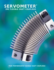
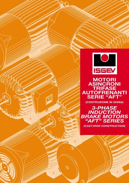
<strong>MOTORI</strong><br />
<strong>ASINCRONI</strong><br />
<strong>TRIFASE</strong><br />
<strong>AUTOFRENANTI</strong><br />
<strong>SERIE</strong> “AFT”<br />
(COSTRUZIONE IN GHISA)<br />
3-PHASE<br />
INDUCTION<br />
BRAKE MOTORS<br />
“AFT” <strong>SERIE</strong>S<br />
(CAST-IRON CONSTRUCTION)
<strong>MOTORI</strong> <strong>ASINCRONI</strong> <strong>TRIFASE</strong> <strong>AUTOFRENANTI</strong> <strong>SERIE</strong> “AFT”<br />
INDUCTION BRAKE MOTORS “AFT” <strong>SERIE</strong>S<br />
ISGEV S.p.A. progetta e costruisce<br />
motori elettrici fin dal 1948.<br />
È presente sul mercato italiano<br />
e recentemente anche su quelli<br />
europei e americani, proponendo<br />
motori affidabili, di alta qualità.<br />
La recente evoluzione tecnologica<br />
sia progettuale che produttiva e la<br />
rinnovata organizzazione aziendale<br />
conformata alle indicazioni delle<br />
norme ISO 9001:2000 sono garanzia<br />
di costante orientamento verso<br />
obiettivi di qualità e garanzia per il<br />
Cliente.<br />
ISGEV S.p.A. has been designing<br />
and constructing electric motors<br />
since 1948.<br />
The company is present on the Italian<br />
market with its reliable, high-quality<br />
motors, which have been recently<br />
launched on the European and<br />
American markets as well.<br />
The recent technological evolution<br />
in terms of both design and<br />
production, and the renewed<br />
company organization certified for<br />
conformity to ISO 9001:2000<br />
Standards provide firm guarantees<br />
of the company's constant orientation<br />
towards the achievement of higher<br />
and higher quality objectives for<br />
assured performance and for the<br />
total satisfaction of the client.<br />
Generalità - General characteristics<br />
I motori della serie AFT sono motori elettrici asincroni trifase autofrenanti derivati dai motori della<br />
serie A. Il freno a disco applicato è del tipo ad alimentazione in corrente continua e può essere<br />
alimentato mediante circuito raddrizzatore fornito con il motore stesso la cui tensione nominale è<br />
230±10%V 50/60Hz monofase. Il comando di frenatura/sblocco freno può essere dato separatamente<br />
o meno dal comando di partenza/arresto del motore. I pregi di questa serie sono:<br />
• elevata rapidità di frenatura e sblocco del freno<br />
• silenziosità negli interventi (
Forme costruttive - Construction forms<br />
3<br />
La serie di motori AFT prevede tutte le forme costruttive<br />
unificate e risponde alle seguenti norme:<br />
• IEC 34-1 Caratteristiche elettriche di funzionamento<br />
• IEC 34-7 Forme costruttive<br />
• IEC 34-5 Gradi di protezione meccanica<br />
• IEC 72 Dimensioni e potenze forme costruttive B3-B5-<br />
B14 e derivate<br />
In sede di ordine è sempre opportuno precisare la forma<br />
costruttiva, le forme costruttive disponibili sono riportate<br />
nella seguente tabella<br />
The AFT series motors include all the unified construction<br />
forms and comply with the following standards:<br />
• IEC34-1Electrical operating characteristics<br />
• IEC34-7Construction forms<br />
• IEC34-5Degrees of mechanical protection<br />
• IEC72Dimensions and power ratings, construction forms<br />
B3-B5-B14 and derived configurations.<br />
When ordering always indicate the construction form.<br />
Available construction forms are indicated in the following<br />
table<br />
B3<br />
IM B3<br />
IM 1001<br />
B5<br />
IM B5<br />
IM 3001<br />
B6<br />
IM B6<br />
IM 1051<br />
B7<br />
IM B7<br />
IM 1061<br />
B8<br />
IM B8<br />
IM 1071<br />
B14<br />
IM B14<br />
IM 3601<br />
V1<br />
IM V1<br />
IM 3011<br />
V3<br />
IM V3<br />
IM 3031<br />
V5<br />
IM V5<br />
IM 1011<br />
V6<br />
IM V6<br />
IM 1031<br />
V18<br />
IM V18<br />
IM 3611<br />
V19<br />
IM V19<br />
IM 3631<br />
B3/B5<br />
IM B35<br />
IM 2001<br />
B3/B14<br />
IM B34<br />
IM 2101<br />
B6/B5<br />
IM 2051<br />
B6/B14<br />
IM 2151<br />
B7/B5<br />
IM 2061<br />
B7/B14<br />
IM 2161<br />
B8/B5<br />
IM 2071<br />
B8/B14<br />
IM 2171<br />
V5/V1<br />
IM V15<br />
IM 2011<br />
V5/V18<br />
IM V15<br />
IM 2111<br />
V6/V3<br />
IM V36<br />
IM 2031<br />
V6/V19<br />
IM V36<br />
IM 2131<br />
Per altre esecuzioni quali: flange, forme costruttive speciali,<br />
sporgenze d'albero speciali o doppie, cuscinetti maggiorati<br />
è necessario consultarci.<br />
Please contact our offices for other configurations, such as<br />
flanges, special construction forms, special or double shaft<br />
projections and oversized bearings.
<strong>MOTORI</strong> <strong>ASINCRONI</strong> <strong>TRIFASE</strong> <strong>AUTOFRENANTI</strong> <strong>SERIE</strong> AFT<br />
SELF-BRAKING 3-PHASE INDUCTION MOTORS “AFT” <strong>SERIE</strong>S<br />
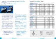
NOMENCLATURA <strong>MOTORI</strong> <strong>SERIE</strong> “AFT” 71 ÷ 160 - COMPONENT LIST MOTORS <strong>SERIE</strong>S “AFT” 71 ÷ 160<br />
1.01 6 2 14 15 7.02 7 1.02<br />
1.04<br />
33.02<br />
33<br />
21<br />
29<br />
3 3.01<br />
1.09<br />
1.05<br />
1.06<br />
33.07<br />
33.03<br />
30<br />
2.02<br />
4<br />
1.07<br />
9<br />
2.03<br />
9.01<br />
2.10<br />
8<br />
4<br />
1<br />
10.01<br />
33.33<br />
10<br />
4.02<br />
FORMA COSTRUTTIVA IM B3<br />
ASSEMBLY IM B3<br />
3.02<br />
5<br />
FORMA COSTRUTTIVA IM B5<br />
ASSEMBLY IM B5<br />
FORMA COSTRUTTIVA IM B14<br />
ASSEMBLY IM B14<br />
1 Albero - Shaft<br />
6 Coperchio L.A. - Driving end cover<br />
1.01 Cuscinetto L.A. - Driving end bearing<br />
7 Coperchio L.O. - Non-driving end cover<br />
1.02 Cuscinetto L.O. - Non-driving end bearing<br />
7.02 Anello seeger arresto cuscinetto - Bearing retention circlip<br />
1.04 Anello seeger arresto cuscinetto - Bearing retention circlip<br />
8 Calotta copriventola - Fan cover<br />
1.05 Anello di tenuta L.A. (a richista) - Seal Ring (on request)<br />
9 Ventola - Fan<br />
1.06 Anello di tenuta L.O. (a richista) - Seal Ring (on request)<br />
9.01 Fascetta fissaggio ventola - Fan fastening clamp<br />
1.07 Linguetta - Key<br />
10 Tirante - Tie-rod<br />
1.09 Molla di compensazione - Compensating spring<br />
10.01 Dado - Nut<br />
2 Cassa - Casing<br />
14 Pacco statore - Stator<br />
2.02 Morsettiera - Terminal board<br />
15 Pacco rotore - Rotor<br />
2.03 Vite fissaggio morsettiera - Terminal board fastening screw<br />
21 Targhetta dati - Data plate<br />
2.10 Spina di arresto pacco - Stator stop spin<br />
29 Guarnizione scatola morsettiera - Terminal box seal<br />
3 Scatola morsettiera - Terminal box<br />
30 Guarnizione coprimorsettiera - Terminal board cover gasket<br />
3.01 Vite fissaggio scatola morsettiera - Screw for fixing terminal box 33 Gruppo freno completo - Complete brake unit<br />
3.02 Pressacavo - Cable gland<br />
33.02 Leva di sblocco freno (a richiesta) - Brake release lever (on request)<br />
4 Copri morsettiera - Terminal board cover<br />
33.03 Anello seeger arresto mozzo - Breaking hub seeger ring<br />
4.02 Vite fissaggio coprimorsettiera - Terminal board cover fastening screw 33.07 Linguetta - Tab<br />
5 Vite di terra - Earth screw<br />
33.33 Raddrizzatore (APR) - Rectifier (APR)<br />
NOTE - NOTE Golfare di sollevamento sulle grandezze 132÷160 - Lifting eyebolt di sollevamento for size 132÷160<br />
N. 2 pressacavi (3.02) sulla grandezza 132÷160 - Nb. 2 cable gland (3.02) for size 132÷160<br />
Sulle grandezze 63-71 pressocavo rivolto lato calotta - On sizes 63-71 cable gland facing cap side
Opzioni - Options<br />
5<br />
Come accessori opzionali è possibile avere:<br />
• Leva di sblocco manuale<br />
• Isolamento in classe H<br />
• Grado di protezione IP56<br />
• Tropicalizzazione<br />
• Termoprotettori<br />
• Albero e flangia speciale<br />
• Scaldiglie anticondensa<br />
• Encoder o dinamo tachimetriche<br />
• Servoventilazione<br />
• Sistemi di lubrificazione con grassi e cuscinetti speciali<br />
• Cicli di verniciatura speciali per ambienti particolari<br />
• Uscita asse posteriore<br />
• Fori di scarico condensa<br />
Optional accessories include:<br />
• Manual release lever<br />
• Class H insulation<br />
• Degree of protection IP56<br />
• Tropicalisation<br />
• Overload cutouts<br />
• Special shaft and flange<br />
• Anti-condensation heaters<br />
• Encoder or speedometer dynamo<br />
• Servo-ventilation<br />
• Lubrication systems with special greases and bearings<br />
• Special painting cycles for particular operating<br />
environments<br />
• Rear axis output<br />
• Condensation drain holes<br />
Freno di sicurezza - Safety brake<br />
Funzionamento<br />
Quando l’elettromagnete (5) viene alimentato attrae l’ancora<br />
(6) grazie al campo magnetico indotto caricando le molle<br />
di spinta; questo permette al disco (7), accoppiato all’albero<br />
per mezzo di un mozzo scanalato (8) di ruotare liberamente.<br />
In mancanza di alimentazione il campo magnetico cessa,<br />
le molle spingono l’ancora contro il disco frenando l’albero<br />
del motore. Vedi fig.B<br />
Operation<br />
When the electromagnet (5) is fed, it attracts the anchor (6)<br />
thanks to the induced magnetic field, loading the thrust<br />
springs. This allows the disc (7), coupled to the shaft by<br />
means of a grooved hub (8), to rotate freely.<br />
During a power outage, the magnetic field is no longer<br />
generated, the springs push the anchor against the disc,<br />
thus braking the motor shaft. See fig.B<br />
1<br />
traferro<br />
air gap<br />
2<br />
3<br />
7<br />
4<br />
6<br />
5<br />
fig.B
<strong>MOTORI</strong> <strong>ASINCRONI</strong> <strong>TRIFASE</strong> <strong>AUTOFRENANTI</strong> <strong>SERIE</strong> AFT<br />
SELF-BRAKING 3-PHASE INDUCTION MOTORS “AFT” <strong>SERIE</strong>S<br />
Regolazione del freno - Brake adjustment<br />
Prima di eseguire ogni operazione sul freno si raccomanda<br />
di togliere l’alimentazione e, se esso è in funzione da diverse<br />
ore, lasciar trascorrere un certo tempo per far raffreddare<br />
le superfici. La regolazione del traferro avviene mediante i<br />
registri (1) dopo avere allentato le viti di fissaggio (2). Prima<br />
di iniziare ad usare il freno assicurarsi che tali viti siano<br />
saldamente bloccate nella flangia di supporto dello stesso.<br />
È importante prima di utilizzare il freno regolare la coppia<br />
frenante rispettando i dati riportati nelle tabelle<br />
che seguono (CARATTERISTICHE FRENO).Per regolare la<br />
coppia frenante bisogna intervenire sulla ghiera (3), la quale<br />
agisce a sua volta sulle molle di coppia (4). Prima di effettuare<br />
la regolazione del traferro, assicurarsi che l’albero non abbia<br />
alcun momento torcente e che il freno sia elettricamente<br />
escluso.<br />
Before carrying out any operation on the brake, cut off the<br />
power supply and, if the brake has been operating for a few<br />
hours, wait until the surfaces have cooled down. The air<br />
gap is adjusted using the registers (1) after having loosened<br />
the fastening screws (2). Before starting to use the brake,<br />
make sure that the screws are firmly tightened in the support<br />
flange. Before using the brake, it is important to adjust the<br />
braking torque based on the data indicated in the following<br />
tables (BRAKE CHARACTERISTICS). To adjust the braking<br />
torque, use the ring nut (3), which engages the torque<br />
springs (4). Before adjusting the air gap, make sure that the<br />
shaft does not have any bending moment and that the brake<br />
is electrically insulated.<br />
6<br />
Manutenzione e riparazione - Maintenance and repairs<br />
È necessaria una frequente ispezione del freno in tutte le<br />
sue parti. Il consumo dipende da numerosi fattori: l’inerzia,<br />
la velocità del motore, la frequenza degli interventi; per<br />
questo motivo non è possibile dare una indicazione generale<br />
relativa al numero di interventi dopo i quali è necessario<br />
sostituire il disco, pulire e regolare il traferro. Le operazioni<br />
di ispezione del freno devono essere fatte seguendo quanto<br />
riportato nella sezione precedente: regolazione del freno.<br />
Assicurarsi dopo l’ispezione che il traferro sia correttamente<br />
regolato.<br />
All brake parts must be inspected on a regular basis. Wear<br />
depends on many factors: inertia, motor speed and frequency<br />
of operations. For this reason it is not possible to provide<br />
a general indication about the number of operations after<br />
which the disc must be replaced and the air gap cleaned<br />
and adjusted. The brake inspection operations must be<br />
carried out according to what is indicated in the previous<br />
section regarding the brake adjustment. After an inspection,<br />
make sure that the air gap is properly adjusted.
Gradi di protezione - Degrees of protection<br />
7<br />
Di norma i motori sono disponibili con grado di protezione<br />
IP55. Su richiesta viene fornito il gruppo frenante in<br />
esecuzione stagna (vedi fig.A), con grado di protezione<br />
IP56, particolarmente indicato per ambienti salini e impiego<br />
navale.<br />
Normally, motors are available with degree of protection<br />
IP55. On request, the braking unit can be supplied in the<br />
watertight configuration (see fig.A) with degree of protection<br />
IP56, which is particularly suitable for saline environments<br />
and naval applications.<br />
fig.A<br />
Tipo pressacavo - Type cable gland<br />
Nella tabella sono riportati il numero di pressacavi e la<br />
dimensione del cavo di passaggio.<br />
The number of cable gland and the dimension of the same<br />
are listed in the cable.<br />
TIPO PRESSACAVO - TYPE CABLE GLAND<br />
ALTEZZA D’ASSE Nr.<br />
FRAME N.<br />
PRESSACAVO DI <strong>SERIE</strong><br />
CABLE GLAND STANDARD<br />
Ø ESTERNO MAX DEL CAVO<br />
MAX EXTERNAL CABLE DIAM.<br />
PRESSACAVO SU RICHIESTA<br />
CABLE GLAND ON REQUEST<br />
71 ÷ 90 1*<br />
Pg 13,5<br />
Ø 12<br />
M20 X 1,5<br />
100 - 112 1*<br />
Pg 16<br />
Ø 16<br />
M25 X 1,5<br />
132 2<br />
Pg 21<br />
Ø 20<br />
M32 X 1,5<br />
160 2<br />
Pg 29<br />
Ø 27<br />
M40 X 1,5<br />
* Serie AFT con sblocco manuale a vite con n° 2 pressacavi<br />
Series AFT with manual screw release with n° 2 cable gland
<strong>MOTORI</strong> <strong>ASINCRONI</strong> <strong>TRIFASE</strong> <strong>AUTOFRENANTI</strong> <strong>SERIE</strong> AFT<br />
SELF-BRAKING 3-PHASE INDUCTION MOTORS “AFT” <strong>SERIE</strong>S<br />
Messa a terra<br />
Tutti i motori hanno un morsetto di messa a terra interno<br />
alla scatola morsettiera e uno esterno sulla cassa.<br />
Earthing<br />
All motors are equipped with one earthing connector inside<br />
the terminal box and another on the outside of the casing.<br />
Collegamenti<br />
I motori di serie sono disponibili per alimentazione a 230/400<br />
o 400/690 Volt 50 Hertz, tensioni e frequenze diverse su<br />
richiesta.<br />
Connections<br />
Standard motors are available for a 230/400 or 400/690 Volt<br />
50 Hertz power supply. Different voltage and frequency<br />
ratings are available on request.<br />
8<br />
Schema n° 82-00002 -1 - Diagram n° 82-00002 -1<br />
Schema di collegamento della bobina freno, con alimentazione separata per motore ad una velocità.<br />
Wiring diagram of the brake coil, with separate power supply for single-speed motor.<br />
Avvolgimento collegato a stella tensione maggiore.<br />
Winding which is star-connected at a higher voltage.<br />
Avvolgimento collegato a triangolo tensione minore.<br />
Winding which is delta-connected at a lower voltage.<br />
ALIMENTATORE AP o APR<br />
SUPPLIER AP OR APR<br />
ALIMENTATORE AP o APR<br />
SUPPLIER AP OR APR<br />
W2 U2 V2<br />
ROSSO - RED<br />
+<br />
BOBINA FRENO<br />
BRAKE WINDING<br />
W2 U2 V2<br />
ROSSO - RED<br />
+<br />
BOBINA FRENO<br />
BRAKE WINDING<br />
U1 V1 W1<br />
-<br />
NERO - BLACK<br />
U1 V1 W1<br />
-<br />
NERO - BLACK<br />
R S T<br />
LINEA - SUPPLY<br />
ALIMENTAZIONE SEPARATA 230 Volt/50 - 60 Hz<br />
SEPARATE POWER SUPPLY 230 Volt/50 - 60 Hz<br />
R S T<br />
LINEA - SUPPLY<br />
ALIMENTAZIONE SEPARATA 230 Volt/50 - 60 Hz<br />
SEPARATE POWER SUPPLY 230 Volt/50 - 60 Hz<br />
Schema n° 82-00003-1 - Diagram n° 82-00003-1<br />
Schema di collegamento della bobina freno,con alimentazione separata per motore a doppia velocita'<br />
con avvolgimento unico a poli commutabili tipo Dahlander.<br />
Wiring diagram of the brake coil, with separate power supply, for two-speed motor<br />
with single winding with commutable poles Dahlander type.<br />
Avvolgimento collegato per alta velocità.<br />
Winding connected for a high speed.<br />
Avvolgimento collegato per bassa velocità.<br />
Winding connected for a low speed.<br />
ALIMENTATORE AP o APR<br />
SUPPLIER AP o APR<br />
ALIMENTATORE AP o APR<br />
SUPPLIER AP OR APR<br />
W2 U2 V2<br />
ROSSO - RED<br />
+<br />
BOBINA FRENO<br />
BRAKE WINDING<br />
W2 U2 V2<br />
ROSSO - RED<br />
+<br />
BOBINA FRENO<br />
BRAKE WINDING<br />
U1 V1 W1<br />
-<br />
NERO - BLACK<br />
U1 V1 W1<br />
-<br />
NERO - BLACK<br />
R S T<br />
LINEA - SUPPLY<br />
ALIMENTAZIONE SEPARATA 230 Volt/50 - 60 Hz<br />
SEPARATE POWER SUPPLY 230 Volt/50 - 60 Hz<br />
R S T<br />
LINEA - SUPPLY<br />
ALIMENTAZIONE SEPARATA 230 Volt/50 - 60 Hz<br />
SEPARATE POWER SUPPLY 230 Volt/50 - 60 Hz<br />
Schema n° 82-00004-1 - Diagram n° 82-00004-1<br />
Schema di collegamento della bobina freno, con alimentazione separata per motore a doppia velocità<br />
con due avvolgimenti separati.<br />
Wiring diagram of the brake coil, with separate power supply for two-speed motor<br />
with two separate windings.<br />
Avvolgimento collegato per alta velocità.<br />
Winding connected for a high speed.<br />
Avvolgimento collegato per bassa velocità.<br />
Winding connected for a low speed.<br />
ALIMENTATORE AP o APR<br />
SUPPLIER AP o APR<br />
ALIMENTATORE AP o APR<br />
SUPPLIER AP o APR<br />
W2 U2 V2<br />
ROSSO - RED<br />
+<br />
BOBINA FRENO<br />
BRAKE WINDING<br />
W2 U2 V2<br />
ROSSO - RED<br />
+<br />
BOBINA FRENO<br />
BRAKE WINDING<br />
U1 V1 W1<br />
-<br />
NERO - BLACK<br />
U1 V1 W1<br />
-<br />
NERO - BLACK<br />
R S T<br />
LINEA - SUPPLY<br />
ALIMENTAZIONE SEPARATA 230 Volt/50 - 60 Hz<br />
SEPARATE POWER SUPPLY 230 Volt/50 - 60 Hz<br />
R S T<br />
LINEA - SUPPLY<br />
ALIMENTAZIONE SEPARATA 230 Volt/50 - 60 Hz<br />
SEPARATE POWER SUPPLY 230 Volt/50 - 60 Hz
2 POLI/POLES<br />
9<br />
CARATTERISTICHE A VOLT 400 HZ50 / PERFORMANCE DATA AT V 400 HZ50<br />
CARATTERISTICHE FRENO / BRAKE CHARACTERISTICS<br />
Tipo Potenza Velocità Corrente Rendimento F. di P. I Spunto C Spunto C Max PD 2 Tipo Traferro H Coppia Freno Tempi interv. Corrente Potenza<br />
Freno Air gap H Statica/Dinamica chius./aper. Freno Freno<br />
Type<br />
Pick-up<br />
Power Speed Current Efficiency P.F. I Pick-up torque<br />
PD 2 Brake<br />
Static/Dinamic Closed/Open Brake Brake<br />
[kW] [min -1 type<br />
Brake Torque Times Current Power<br />
] [A] % Cosϕ *Ispu/In *Cspu/Cn *Cmax/Cr kg x m 2 [mm] Nm [ms] [A] [W]<br />
AFT 71 A 2 0,37 2820 0,95 68 0,81 4,3 2 2,3 0,001 K02 0,2 8/6,4 15/30 0,13 30<br />
AFT 71 B 2 0,55 2820 1,38 70 0,82 4,7 2,1 2 0,0017 K02 0,2 8/6,4 15/30 0,13 30<br />
AFT 80 A 2 0,75 2820 1,81 73 0,8 4,5 2,3 2,6 0,0038 K03 0,2 12/9,6 15/30 0,16 35<br />
AFT 80 B 2 1,1 2820 2,57 76 0,82 5,3 2,7 2,7 0,0046 K03 0,2 12/9,6 15/30 0,16 35<br />
AFT 90 S 2 1,5 2840 3,24 80 0,83 5,9 2,50 2,7 0,0084 K04 0,2 16/12,8 15/40 0,2 35<br />
AFT 90 L 2 2,2 2840 4,76 80 0,83 5,5 2,5 2,6 0,0104 K04 0,2 16/12,8 15/40 0,2 35<br />
AFT 100 L 2 3,0 2840 6,1 82 0,85 6 2,5 2,8 0,017 K05 0,3 35/28 20/45 0,3 45<br />
AFT 112 M 2 4,0 2910 8,1 85 0,85 7,8 2,6 3,3 0,0315 K06 0,3 60/48 25/85 0,32 50<br />
AFT 132 SA 2 5,5 2900 10,7 85 0,87 7 2,6 3,3 0,055 K07 0,3 80/64 50/95 0,36 65<br />
AFT 132 SB 2 7,5 2900 14,3 86 0,86 7,7 2,5 3,4 0,059 K07 0,3 80/64 50/95 0,36 65<br />
AFT 132 M 2 9,2 2880 18,1 86 0,85 7,2 2,8 2,8 0,064 K07 0,3 80/64 50/95 0,36 65<br />
AFT 160 MA 2 11,0 2910 21,4 86 0,86 7,6 2,5 3,6 0,092 K08 0,3 150/120 60/100 0,39 65<br />
AFT 160 MB 2 15,0 2920 28,6 87 0,87 7,5 2,5 3,6 0,11 K08 0,3 150/120 60/100 0,39 95<br />
AFT 160 L 2 18,5 2910 35,4 86 0,87 8,3 3 3,4 0,14 K08D 0,4 300/240 60/100 0,39 95<br />
4 POLI/POLES<br />
CARATTERISTICHE A VOLT 400 HZ50 / PERFORMANCE DATA AT V 400 HZ50<br />
CARATTERISTICHE FRENO / BRAKE CHARACTERISTICS<br />
Tipo Potenza Velocità Corrente Rendimento F. di P. I Spunto C Spunto C Max PD 2 Tipo Traferro H Coppia Freno Tempi interv. Corrente Potenza<br />
Freno Air gap H Statica/Dinamica chius./aper. Freno Freno<br />
Type<br />
Pick-up<br />
Power Speed Current Efficiency P.F. I Pick-up<br />
[kW] [min -1 torque<br />
PD 2 Brake<br />
Static/Dinamic Closed/Open Brake Brake<br />
] [A] % Cosϕ *Ispu/In *Cspu/Cn *Cmax/Cr kg x m 2 type<br />
Brake Torque Times Current Power<br />
[mm] Nm [ms] [A] [W]<br />
AFT 71 A 4 0,25 1390 0,76 63 0,73 3,4 1,8 2 0,0029 K02 0,2 8/6,4 15/30 0,13 30<br />
AFT 71 B 4 0,37 1380 1,1 66 0,72 3,4 2,1 2,2 0,0037 K02 0,2 8/6,4 15/30 0,13 30<br />
AFT 80 A 4 0,55 1390 1,5 73 0,74 4,2 2 2,2 0,0064 K03 0,2 12/9,6 15/30 0,16 35<br />
AFT 80 B 4 0,75 1400 1,86 74 0,78 4,9 2,1 2,1 0,0079 K03 0,2 12/9,6 15/30 0,16 35<br />
AFT 90 S 4 1,1 1410 2,6 79 0,78 4,9 2,2 2,4 0,013 K04 0,2 16/12,8 15/40 0,2 35<br />
AFT 90 L 4 1,5 1420 3,3 81 0,78 4,4 2,2 2,4 0,016 K04 0,2 16/12,8 15/40 0,2 35<br />
AFT 100 LA 4 2,2 1425 4,8 81 0,82 6 2,2 2,6 0,0406 K05 0,3 35/28 20/45 0,3 45<br />
AFT 100 LB 4 3,0 1435 6,4 81 0,85 5,4 2,2 2,4 0,0516 K05 0,3 35/28 20/45 0,3 45<br />
AFT 112 M 4 4,0 1440 8,2 84 0,86 6,6 2,8 3 0,0805 K06 0,3 60/48 25/85 0,32 50<br />
AFT 132 S 4 5,5 1440 11 85 0,85 6 2,5 2,9 0,122 K07 0,3 80/64 50/95 0,36 65<br />
AFT 132 MA 4 7,5 1450 14,7 87 0,85 6,1 2,7 3 0,142 K07 0,3 80/64 50/95 0,36 65<br />
AFT 132 MB 4 9,2 1435 18,8 86 0,82 6,2 3 3 0,172 K07 0,3 80/64 50/95 0,36 65<br />
AFT 160 M 4 11,0 1450 21,9 87 0,85 7,4 2,5 2,9 0,24 K08 0,3 150/120 60/100 0,39 95<br />
AFT 160 L 4 15,0 1440 28,6 87 0,87 7 2,7 3,1 0,3 K08D 0,4 300/240 60/100 0,39 95<br />
* Coppie e Correnti in Rapporto al Pieno Carico - Torque and current values listed in respect to full loads<br />
Dati non impegnativi, con riserva di apportare modifiche - These data are not legally binding. The Manufacturer reserves the right to modify its products without notice.
<strong>MOTORI</strong> <strong>ASINCRONI</strong> <strong>TRIFASE</strong> <strong>AUTOFRENANTI</strong> <strong>SERIE</strong> AFT<br />
SELF-BRAKING 3-PHASE INDUCTION MOTORS “AFT” <strong>SERIE</strong>S<br />
6 POLI/POLES<br />
CARATTERISTICHE A VOLT 400 HZ50 / PERFORMANCE DATA AT V 400 HZ50<br />
CARATTERISTICHE FRENO / BRAKE CHARACTERISTICS<br />
Tipo Potenza Velocità Corrente Rendimento F. di P. I Spunto C Spunto C Max PD 2 Tipo Traferro H Coppia Freno Tempi interv. Corrente Potenza<br />
Freno Air gap H Statica/Dinamica chius./aper. Freno Freno<br />
Type<br />
Pick-up<br />
Power Speed Current Efficiency P.F. I Pick-up<br />
[kW] [min -1 torque<br />
PD 2 Brake<br />
Static/Dinamic Closed/Open Brake Brake<br />
] [A] % Cosϕ *Ispu/In *Cspu/Cn *Cmax/Cr kg x m 2 type<br />
Brake Torque Times Current Power<br />
[mm] Nm [ms] [A] [W]<br />
AFT 71 A 6 0,18 850 0,71 48 0,77 2,2 1,3 1,5 0,0029 K02 0,2 8/6,4 15/30 0,13 30<br />
10<br />
AFT 71 B 6 0,25 850 1 50 0,73 2,5 1,4 1,5 0,0037 K02 0,2 8/6,4 15/30 0,13 30<br />
AFT 80 A 6 0,37 930 1,1 65 0,74 3 1,9 2 0,01 K03 0,2 12/9,6 15/30 0,16 35<br />
AFT 80 B 6 0,55 945 1,6 68 0,74 3,3 1,9 2,1 0,013 K03 0,2 12/9,6 15/30 0,16 35<br />
AFT 90 S 6 0,75 940 2,05 71 0,73 3,2 1,9 2 0,021 K04 0,2 16/12,8 15/40 0,2 35<br />
AFT 90 L 6 1,1 940 2,9 74 0,74 3,4 1,9 2 0,027 K04 0,2 16/12,8 15/40 0,2 35<br />
AFT 100 L 6 1,5 930 3,6 76 0,78 3,9 1,9 2,1 0,048 K05 0,3 35/28 20/45 0,3 45<br />
AFT 112 M 6 2,2 945 5,3 79 0,78 4,7 2 2,4 0,092 K06 0,3 60/48 25/85 0,32 50<br />
AFT 132 S 6 3 950 6,8 80 0,78 4 1,7 2,2 0,122 K07 0,3 80/64 50/95 0,36 65<br />
AFT 132 MA 6 4 960 9,1 83 0,78 5,2 2,5 2,4 0,172 K07 0,3 80/64 50/95 0,36 65<br />
AFT 132 MB 6 5,5 960 11,9 84 0,8 4,7 2,1 2,4 0,212 K07 0,3 80/64 50/95 0,36 65<br />
AFT 160 M 6 7,5 965 15,9 88 0,78 6,2 2,3 3,2 0,35 K08 0,3 150/120 60/100 0,39 65<br />
AFT 160 L 6 11 955 22,9 88 0,79 5,5 2,2 2,9 0,44 K08D 0,4 300/240 60/100 0,39 95<br />
8 POLI/POLES<br />
CARATTERISTICHE A VOLT 400 HZ50 / PERFORMANCE DATA AT V 400 HZ50<br />
CARATTERISTICHE FRENO / BRAKE CHARACTERISTICS<br />
Tipo Potenza Velocità Corrente Rendimento F. di P. I Spunto C Spunto C Max PD 2 Tipo Traferro H Coppia Freno Tempi interv. Corrente Potenza<br />
Freno Air gap H Statica/Dinamica chius./aper. Freno Freno<br />
Type<br />
Pick-up<br />
Power Speed Current Efficiency P.F. I Pick-up torque<br />
PD 2 Brake<br />
Static/Dinamic Closed/Open Brake Brake<br />
[kW] [min -1 ] [A] % Cosϕ *Ispu/In *Cspu/Cn *Cmax/Cr kg x m 2 type<br />
Brake Torque Times Current Power<br />
[mm] Nm [ms] [A] [W]<br />
AFT 71 A 8 0,09 670 0,6 40 0,57 2 1,9 2 0,0029 K02 0,2 8/6,4 15/30 0,13 30<br />
AFT 71 B 8 0,12 640 1,1 43 0,58 1,6 1,5 1,5 0,0037 K02 0,2 8/6,4 15/30 0,13 30<br />
AFT 80 A 8 0,18 700 1,5 55 0,64 2,6 1,7 2 0,01 K03 0,2 12/9,6 15/30 0,16 35<br />
AFT 80 B 8 0,25 700 1,86 54 0,62 2,5 2,2 2,1 0,013 K03 0,2 12/9,6 15/30 0,16 35<br />
AFT 90 S 8 0,37 700 2,6 60 0,65 2,9 1,8 2,1 0,021 K04 0,2 16/12,8 15/40 0,2 35<br />
AFT 90 L 8 0,55 700 3,3 65 0,66 3 1,7 1,8 0,027 K04 0,2 16/12,8 15/40 0,2 35<br />
AFT 100 LA 8 0,75 700 4,8 72 0,64 3,9 2,4 2,3 0,048 K05 0,3 35/28 20/45 0,3 45<br />
AFT 100 LB 8 1,1 700 6,4 72 0,7 3,8 2 2,1 0,06 K05 0,3 35/28 20/45 0,3 45<br />
AFT 112 M 8 1,5 705 8,2 76 0,72 3,6 1,7 2 0,105 K06 0,3 60/48 25/85 0,32 50<br />
AFT 132 S 8 2,2 705 11 77 0,73 3,8 1,6 2 0,163 K07 0,3 80/64 50/95 0,36 65<br />
AFT 132 M 8 3 710 14,7 78 0,73 3,8 1,8 2 0,21 K07 0,3 80/64 50/95 0,36 65<br />
AFT 160 MA 8 4 715 18,8 81 0,73 5,1 2,5 2,7 0,365 K08 0,3 150/120 60/100 0,39 95<br />
AFT 160 MB 8 5,5 710 21,9 83 0,76 5,3 2,5 2,7 0,45 K08 0,3 150/120 60/100 0,39 95<br />
AFT 160 L 8 7,5 710 28,6 84 0,77 5,7 2,4 2,7 0,56 K08D 0,4 300/240 60/100 0,39 95<br />
* Coppie e Correnti in Rapporto al Pieno Carico - Torque and current values listed in respect to full loads<br />
Dati non impegnativi, con riserva di apportare modifiche - These data are not legally binding. The Manufacturer reserves the right to modify its products without notice.
2/4 POLI/POLES<br />
11<br />
CARATTERISTICHE A VOLT 400 HZ50 / PERFORMANCE DATA AT V 400 HZ50<br />
CARATTERISTICHE FRENO / BRAKE CHARACTERISTICS<br />
Tipo Potenza Velocità Corrente I Spunto C Spunto C Max PD 2 Tipo Traferro H Coppia Freno Tempi interv. Corrente Potenza<br />
Freno Statica/Dinamica chius./aper. Freno Freno<br />
Type Power Speed Current I Pick-up Pick-up torque PD 2<br />
Air gap H<br />
Brake<br />
Static/Dinamic Closed/Open Brake Brake<br />
[kW] [min -1 ] [A] *Ispu/In *Cospu/Cn *Cmax/Cr<br />
type<br />
Brake Torque Times Current Power<br />
2 4 2 4 2 4 2 4 2 4 2 4 kg x m 2 [mm] Nm [ms] [A] [W]<br />
AFT 71 A 2-4 0,25 0,18 2800 1400 0,55 0,55 4 3,2 1,8 1,8 2 2 0,0027 K02 0,2 8/6,4 15/30 0,13 30<br />
AFT 71 B 2-4 0,44 0,3 2800 1400 1,02 1,02 3,3 2,7 1,7 1,7 1,9 1,9 0,0035 K02 0,2 8/6,4 15/30 0,13 30<br />
AFT 80 A 2-4 0,6 0,44 2850 1440 1,55 1,33 3,9 3 1,9 1,6 1,9 1,9 0,006 K03 0,2 12/9,6 15/30 0,16 35<br />
AFT 80 B 2-4 0,88 0,75 2850 1440 2,2 2 3,6 3 1,8 1,6 2 1,9 0,0075 K03 0,2 12/9,6 15/30 0,16 35<br />
AFT 90 S 2-4 1,3 0,95 2810 1430 3,2 2,6 4,8 4,6 2,2 1,9 1,8 1,9 0,012 K04 0,2 16/12,8 15/40 0,2 35<br />
AFT 90 L 2-4 1,75 1,25 2840 1440 3,7 3,2 4,4 4,5 2,1 2,1 2 2,2 0,015 K04 0,2 16/12,8 15/40 0,2 35<br />
AFT 100 LA 2-4 2,35 1,84 2860 1430 5 4 5,5 5,4 2,3 1,8 2,3 2,1 0,04 K05 0,3 35/28 20/45 0,3 45<br />
AFT 100 LB 2-4 3,1 2,4 2870 1430 6,4 5,3 6,9 6,1 2,4 2,1 2,5 2,4 0,051 K05 0,3 35/28 20/45 0,3 45<br />
AFT 112 M 2-4 4 3,3 2900 1450 8,3 7,2 5,6 5,2 2,3 2,3 2,6 2,6 0,08 K06 0,3 60/48 25/85 0,32 50<br />
AFT 132 S 2-4 5,5 4,4 2900 1450 10,5 8,9 7,2 5,4 2,3 2,1 2,7 2,6 0,12 K07 0,3 80/64 50/95 0,36 65<br />
AFT 132 MA 2-4 7,5 6 2900 1450 13,8 12,1 7 6 2,4 1,8 2,6 2,2 0,14 K07 0,3 80/64 50/95 0,36 65<br />
AFT 160 M 2-4 11,0 8,8 2915 1460 22 18,1 6,3 5,6 2,1 1,8 2,2 2,1 0,24 K08 0,3 150/120 60/100 0,39 95<br />
AFT 160 L 2-4 15 11,8 2900 1450 27,2 23,4 6,5 5,6 2,3 1,8 2,9 2,2 0,3 K08D 0,4 300/240 60/100 0,39 95<br />
4/8 POLI/POLES<br />
CARATTERISTICHE A VOLT 400 HZ50 / PERFORMANCE DATA AT V 400 HZ50<br />
CARATTERISTICHE FRENO / BRAKE CHARACTERISTICS<br />
Tipo Potenza Velocità Corrente I Spunto C Spunto C Max PD 2 Tipo Traferro H Coppia Freno Tempi interv. Corrente Potenza<br />
Freno Statica/Dinamica chius./aper. Freno Freno<br />
Type Power Speed Current I Pick-up Pick-up torque PD 2<br />
Air gap H<br />
Brake<br />
Static/Dinamic Closed/Open Brake Brake<br />
[kW] [min -1 ] [A] *Ispu/In *Cospu/Cn *Cmax/Cr<br />
type<br />
Brake Torque Times Current Power<br />
4 8 4 8 4 8 4 8 4 8 4 8 kg x m 2 [mm] Nm [ms] [A] [W]<br />
AFT 71 B 4-8 0,15 0,09 1420 670 0,45 0,6 2,8 1,8 1,6 1,7 1,9 1,8 0,0035 K02 0,2 8/6,4 15/30 0,13 30<br />
AFT 80 A 4-8 0,26 0,18 1400 700 0,69 0,68 4 2,5 1,7 1,7 2 2 0,001 K03 0,2 12/9,6 15/30 0,16 35<br />
AFT 80 B 4-8 0,37 0,25 1430 690 0,95 0,95 4,2 2,7 1,7 1,7 2 2 0,013 K03 0,2 12/9,6 15/30 0,16 35<br />
AFT 90 S 4-8 0,55 0,37 1400 700 1,43 1,43 5 2,8 2,4 1,9 2,2 2 0,022 K04 0,2 16/12,8 15/40 0,2 35<br />
AFT 90 L 4-8 0,75 0,55 1430 700 1,8 1,8 5 2,5 2,6 1,8 2,8 1,8 0,028 K04 0,2 16/12,8 15/40 0,2 35<br />
AFT 100 LA 4-8 1,1 0,75 1400 700 2,5 2,2 4,3 3,3 1,8 1,9 2,4 2,3 0,047 K05 0,3 35/28 20/45 0,3 45<br />
AFT 100 LB 4-8 1,5 1,1 1430 700 3,3 3,3 5 3,2 2 1,6 2,4 1,9 0,06 K05 0,3 35/28 20/45 0,3 45<br />
AFT 112 M 4-8 2,2 1,5 1400 700 4,8 4 4,8 3,7 1,7 1,6 1,9 2 0,1 K06 0,3 60/48 25/85 0,32 50<br />
AFT 132 S 4-8 3 2,2 1430 705 6,4 6 5,5 3,6 1,9 1,6 2 1,7 0,161 K07 0,3 80/64 50/95 0,36 65<br />
AFT 132 M 4-8 4 3 1430 705 8,3 7,4 5,1 3,8 1,8 1,7 1,9 1,9 0,207 K07 0,3 80/64 50/95 0,36 65<br />
AFT 160 MA 4-8 5,5 4 1450 720 11,2 10,2 6,5 4,4 2,3 2,1 2,5 2 0,365 K08 0,3 150/120 60/100 0,39 95<br />
AFT 160 MB 4-8 7,5 4,8 1430 720 14 11,0 6,1 5 1,9 1,6 2,3 2,5 0,45 K08 0,3 150/120 60/100 0,39 95<br />
AFT 160 L 4-8 10,3 7 1430 720 19,2 16,2 6,3 4,7 2,2 2,2 2,5 2,4 0,56 K08D 0,4 300/240 60/100 0,39 95<br />
* Coppie e Correnti in Rapporto al Pieno Carico - Torque and current values listed in respect to full loads<br />
Dati non impegnativi, con riserva di apportare modifiche - These data are not legally binding. The Manufacturer reserves the right to modify its products without notice.
<strong>MOTORI</strong> <strong>ASINCRONI</strong> <strong>TRIFASE</strong> <strong>AUTOFRENANTI</strong> <strong>SERIE</strong> AFT<br />
SELF-BRAKING 3-PHASE INDUCTION MOTORS “AFT” <strong>SERIE</strong>S<br />
4/6 POLI/POLES<br />
CARATTERISTICHE A VOLT 400 HZ50 / PERFORMANCE DATA AT V 400 HZ50<br />
CARATTERISTICHE FRENO / BRAKE CHARACTERISTICS<br />
Tipo Potenza Velocità Corrente I Spunto C Spunto C Max PD 2 Tipo Traferro H Coppia Freno Tempi interv. Corrente Potenza<br />
Freno Statica/Dinamica chius./aper. Freno Freno<br />
Type Power Speed Current I Pick-up Pick-up torque PD 2<br />
Air gap H<br />
Brake<br />
Static/Dinamic Closed/Open Brake Brake<br />
[kW] [min -1 ] [A] *Ispu/In *Cospu/Cn *Cmax/Cr<br />
type<br />
Brake Torque Times Current Power<br />
4 6 4 6 4 6 4 6 4 6 4 6 kg x m 2 [mm] Nm [ms] [A] [W]<br />
AFT 71 A 4-6 0,125 0,09 1430 900 0,47 0,22 2,8 2,3 1,2 1,4 1,7 1,6 0,0027 K02 0,2 8/6,4 15/30 0,13 30<br />
12<br />
AFT 71 B 4-6 0,18 0,125 1460 915 0,66 0,57 3,2 2,4 1,4 1,5 1,8 1,6 0,0035 K02 0,2 8/6,4 15/30 0,13 30<br />
AFT 80 A 4-6 0,3 0,22 1415 955 0,82 1,05 3,4 2,7 1,5 1,7 1,9 2,2 0,01 K03 0,2 12/9,6 15/30 0,16 35<br />
AFT 80 B 4-6 0,44 0,3 1400 900 1,2 1,24 3,7 3 1,5 1,6 2 2,1 0,013 K03 0,2 12/9,6 15/30 0,16 35<br />
AFT 90 S 4-6 0,66 0,44 1430 950 1,8 1,33 4,2 3,6 1,9 1,9 2,1 2,2 0,022 K04 0,2 16/12,8 15/40 0,2 35<br />
AFT 90 L 4-6 1,1 0,75 1450 950 2,7 2,2 3,8 4 1,5 1,8 2 2,2 0,028 K04 0,2 16/12,8 15/40 0,2 35<br />
AFT 100 LA 4-6 1,3 0,88 1400 950 3 2,3 4,2 4,2 1,7 1,7 1,8 1,9 0,047 K05 0,3 35/28 20/45 0,3 45<br />
AFT 100 LB 4-6 1,75 1,2 1400 950 4,2 3,1 3,8 3,7 1,5 1,6 1,8 1,8 0,06 K05 0,3 35/28 20/45 0,3 45<br />
AFT 112 M 4-6 2,2 1,5 1420 960 4,8 3,8 4,7 4,8 1,5 1,8 2 2,3 0,091 K06 0,3 60/48 25/85 0,32 50<br />
AFT 132 S 4-6 3 2 1450 965 6,3 4,7 4,8 4,6 1,7 1,7 2,7 2,4 0,12 K07 0,3 80/64 50/95 0,36 65<br />
AFT 132 MA 4-6 3,7 2,55 1450 965 7,4 5,7 6,1 5,4 2 2 2,4 2,5 0,17 K07 0,3 80/64 50/95 0,36 65<br />
AFT 132 MB 4-6 4,4 3 1450 970 8,6 6,5 9 6,3 1,9 2,1 2,9 2,7 0,21 K07 0,3 80/64 50/95 0,36 65<br />
AFT 160 M 4-6 6,6 4,4 1460 960 13,7 9,3 6,3 4,9 1,7 1,8 2,7 2,3 0,35 K08 0,3 150/120 60/100 0,39 95<br />
AFT 160 L 4-6 8,8 5,9 1460 960 17 12,4 6,2 4,9 2 1,9 2,7 2,5 0,44 K08D 0,4 300/240 60/100 0,39 95<br />
6/8 POLI/POLES<br />
CARATTERISTICHE A VOLT 400 HZ50 / PERFORMANCE DATA AT V 400 HZ50<br />
CARATTERISTICHE FRENO / BRAKE CHARACTERISTICS<br />
Tipo Potenza Velocità Corrente I Spunto C Spunto C Max PD 2 Tipo Traferro H Coppia Freno Tempi interv. Corrente Potenza<br />
Freno Statica/Dinamica chius./aper. Freno Freno<br />
Type Power Speed Current I Pick-up Pick-up torque PD 2<br />
Air gap H<br />
Brake<br />
Static/Dinamic Closed/Open Brake Brake<br />
[kW] [min -1 ] [A] *Ispu/In *Cospu/Cn *Cmax/Cr<br />
type<br />
Brake Torque Times Current Power<br />
6 8 6 8 6 8 6 8 6 8 6 8 kg x m 2 [mm] Nm [ms] [A] [W]<br />
AFT 80 A 6-8 0,185 0,11 955 700 0,74 0,74 3,2 2,5 1,5 1,2 1,7 1,7 0,01 K03 0,2 12/9,6 15/30 0,16 35<br />
AFT 80 B 6-8 0,295 0,185 900 700 1,26 0,76 3 2,5 1,5 1,2 1,6 1,7 0,013 K03 0,2 12/9,6 15/30 0,16 35<br />
AFT 90 S 6-8 0,44 0,25 920 700 1,4 1,09 4 2,9 1,7 1,7 2,5 2,1 0,022 K04 0,2 16/12,8 15/40 0,2 35<br />
AFT 90 L 6-8 0,66 0,37 950 700 2,1 1,54 2,9 2,9 1,8 1,8 2,2 2,1 0,028 K04 0,2 16/12,8 15/40 0,2 35<br />
AFT 100 LA 6-8 0,88 0,55 950 700 2,3 1,9 3,7 2,9 1,7 1,7 2 2,2 0,047 K05 0,3 35/28 20/45 0,3 45<br />
AFT 100 LB 6-8 1,2 0,75 950 700 3,1 2,2 3,7 2,8 1,5 1,5 1,7 1,8 0,06 K05 0,3 35/28 20/45 0,3 45<br />
AFT 112 M 6-8 1,5 0,88 950 700 3,9 2,8 4,1 3,1 1,5 1,3 2 1,7 0,091 K06 0,3 60/48 25/85 0,32 50<br />
AFT 132 S 6-8 1,85 1,1 970 720 4,5 3,5 5 4,1 1,6 1,8 2,5 2,5 0,12 K07 0,3 60/48 50/95 0,36 65<br />
AFT 132 MB 6-8 3 1,85 970 720 7,1 5,2 5,5 4,7 2,1 2 3 2,6 0,21 K07 0,3 80/64 50/95 0,36 65<br />
AFT 160 M 6-8 4,4 3,3 960 710 9,5 8 4,5 3,6 1,5 1,6 2,2 1,9 0,35 K08 0,3 150/120 60/100 0,39 95<br />
AFT 160 L 6-8 6,6 4,4 970 710 13,8 10,7 5,2 4,4 1,5 1,6 2,3 2,3 0,44 K08D 0,4 300/240 60/100 0,39 95<br />
* Coppie e Correnti in Rapporto al Pieno Carico - Torque and current values listed in respect to full loads<br />
Dati non impegnativi, con riserva di apportare modifiche - These data are not legally binding. The Manufacturer reserves the right to modify its products without notice.
<strong>MOTORI</strong> <strong>ASINCRONI</strong> <strong>TRIFASE</strong> <strong>AUTOFRENANTI</strong> <strong>SERIE</strong> AFT<br />
SELF-BRAKING 3-PHASE INDUCTION MOTORS “AFT” <strong>SERIE</strong>S<br />
13<br />
L<br />
AD<br />
F h9<br />
GA<br />
DB<br />
DIN332<br />
D<br />
LF<br />
LL<br />
ARZIGNANO-Vicenza<br />
HD<br />
H 0<br />
-0,5<br />
HA<br />
AG'<br />
AS<br />
AS<br />
AG<br />
TOLLERANZE<br />
Estremità d'albero D:<br />
j6 fino al Ø 28, k6 oltre.<br />
TOLERANCE<br />
End of shaft (D):<br />
j6 up to Ø 28, k6 above<br />
NOTE<br />
Dal tipo 132, scatola morsettiera<br />
con 2 bocchettoni pressacavo.<br />
Dal tipo 132, golfare di sollevamento.<br />
NOTE<br />
From type 132 on up, terminal box<br />
with 2 cable-gland unions.<br />
From Type 132 on up, lifting eyebolt.<br />
BC<br />
E C B<br />
BB<br />
BA<br />
AA<br />
A<br />
AB<br />
K<br />
O<br />
Dimensioni in millimetri - Dimensions in millimeters<br />
Forma costruttiva IM B3<br />
Assembly IM B3<br />
Estremità d’albero - End of shaft<br />
Grandezza/Size<br />
A<br />
IEC<br />
DIN 332<br />
71<br />
80<br />
90 S<br />
90 L<br />
100 L<br />
112 M<br />
132 S<br />
132 M<br />
160 M<br />
160 L<br />
112 30 136 143 132 63 96 44 90 28 108 34.5 45 71 8 143 7 295 120 120<br />
14 M5 30 5 16<br />
125 34 158 166 142 63 106 44 100 32 120 37 50 80 9 163 9 338 140 120<br />
19 M6 40 6 21.5<br />
140<br />
140<br />
160<br />
190<br />
216<br />
216<br />
254<br />
254<br />
AA AB AC AD AG AG I AS B BA BB BC C H HA HD K L LF LL O D DB E F GA<br />
40<br />
40<br />
48<br />
52<br />
60<br />
60<br />
65<br />
65<br />
180<br />
180<br />
202<br />
228<br />
260<br />
260<br />
310<br />
310<br />
189<br />
189<br />
215<br />
239<br />
268<br />
268<br />
322<br />
322<br />
150<br />
173<br />
185<br />
209<br />
63<br />
75<br />
75<br />
89<br />
114<br />
136<br />
148<br />
165<br />
44<br />
150 63 114 44<br />
53<br />
53<br />
65<br />
209 89 165 65<br />
245<br />
245<br />
105 194.5 80<br />
105<br />
194.5<br />
80<br />
100<br />
125<br />
140<br />
140<br />
140<br />
178<br />
210<br />
254<br />
Dati non impegnativi - con riserva di apportare modifiche / These data are not legally binding. The Manufacturer reserves the right to modify its products without notice.<br />
38<br />
38<br />
46<br />
50<br />
58<br />
58<br />
70<br />
70<br />
127<br />
152<br />
176<br />
184<br />
198<br />
236<br />
272<br />
316<br />
29.5<br />
29.5<br />
39<br />
35<br />
38<br />
38<br />
48<br />
48<br />
56<br />
56<br />
63<br />
70<br />
89<br />
89<br />
108<br />
108<br />
90<br />
90<br />
100<br />
112<br />
132<br />
132<br />
160<br />
160<br />
10<br />
10<br />
10<br />
11<br />
13<br />
13<br />
18<br />
18<br />
185<br />
185<br />
208<br />
232<br />
266<br />
266<br />
322<br />
322<br />
9<br />
9<br />
12<br />
12<br />
12<br />
12<br />
15<br />
15<br />
370<br />
395<br />
456<br />
472<br />
548<br />
586<br />
712<br />
756<br />
156<br />
169<br />
193<br />
200<br />
239<br />
258<br />
323<br />
345<br />
120<br />
120<br />
140<br />
140<br />
160<br />
160<br />
160<br />
160<br />
Tipo pressacavo vedi pag. 7<br />
Type cable gland see page 7<br />
24 M8 50 8 27<br />
24 M8 50 8 27<br />
28 M10 60 8 31<br />
28 M10 60 8 31<br />
38 M12 80 10 41<br />
38 M12 80 10 41<br />
42<br />
42<br />
M16<br />
M16<br />
110<br />
110<br />
12<br />
12<br />
45<br />
45<br />
Grand. Freno<br />
Brake Size<br />
K02<br />
K03<br />
K04<br />
K04<br />
K05<br />
K06<br />
K07<br />
K07<br />
K08<br />
K08/D
nza<br />
<strong>MOTORI</strong> <strong>ASINCRONI</strong> <strong>TRIFASE</strong> <strong>AUTOFRENANTI</strong> <strong>SERIE</strong> AFT CON SBLOCCO MANUALE A VITE<br />
SELF-BRAKING 3-PHASE INDUCTION MOTORS “AFT” <strong>SERIE</strong>S WITH MANUAL SCREW RELEASE<br />
AD<br />
L<br />
AG<br />
AS<br />
AS<br />
O<br />
AG'<br />
K<br />
A<br />
AB<br />
AC<br />
AA<br />
HA<br />
0<br />
H -0,5<br />
HD<br />
BA<br />
LL<br />
BC<br />
B<br />
BB<br />
LF<br />
C<br />
E<br />
D<br />
DB<br />
DIN332<br />
GA<br />
F h9<br />
TOLLERANZE<br />
Estremità d'albero D:<br />
j6 fino al Ø 28, k6 oltre.<br />
TOLERANCE<br />
End of shaft (D):<br />
j6 up to Ø 28, k6 above.<br />
NOTE<br />
Dal tipo 71 al 90, sblocco<br />
con volantino zigrinato.<br />
Dal tipo 132, bocchettoni pressacavo<br />
sullo stesso lato.<br />
Dal tipo 132, golfare di sollevamento.<br />
NOTE<br />
Type 71 to 90, release with knurled<br />
handwheel.<br />
From type 132, cable gland connectors<br />
on the same side.<br />
From Type 132 on up, lifting eyebolt.<br />
Dimensioni in millimetri - Dimensions in millimeters<br />
Forma costruttiva IM B3 - IP 56<br />
Assembly IM B3 - IP 56<br />
Estremità d’albero - End of shaft<br />
Grandezza/Size<br />
A<br />
IEC<br />
DIN 332<br />
71<br />
80<br />
90 S<br />
90 L<br />
100 L<br />
112 M<br />
132 S<br />
132 M<br />
160 M<br />
160 L<br />
112<br />
125<br />
140<br />
140<br />
160<br />
190<br />
216<br />
216<br />
254<br />
254<br />
AA AB AC AD AG AG I AS B BA BB BC C H HA HD K L LF LL O D DB E F GA<br />
30 136 143 139 66 107 57 90 28 108 55.5 45 71 8 143 7 293 120 140<br />
14 M5 30 5 16<br />
34 158 166 149 66 117 57 100 32 120 63 50 80 9 163 9 313 140 140<br />
19 M6 40 6 21.5<br />
40<br />
40<br />
48<br />
52<br />
60<br />
60<br />
65<br />
65<br />
180<br />
180<br />
202<br />
228<br />
260<br />
260<br />
310<br />
310<br />
189<br />
189<br />
215<br />
239<br />
268<br />
268<br />
322<br />
322<br />
157<br />
173<br />
185<br />
217<br />
66<br />
89<br />
89<br />
103<br />
125<br />
138<br />
150<br />
172<br />
57<br />
157 66 125 57<br />
70<br />
70<br />
84<br />
217 103 172 84<br />
159<br />
259<br />
128 207 108<br />
128<br />
207<br />
108<br />
100<br />
125<br />
140<br />
140<br />
140<br />
178<br />
210<br />
254<br />
Dati non impegnativi - con riserva di apportare modifiche / These data are not legally binding. The Manufacturer reserves the right to modify its products without notice.<br />
38<br />
38<br />
46<br />
50<br />
58<br />
58<br />
70<br />
70<br />
127<br />
152<br />
176<br />
184<br />
198<br />
236<br />
272<br />
316<br />
66.5<br />
91.5<br />
101<br />
105<br />
65<br />
103<br />
106<br />
150<br />
56<br />
56<br />
63<br />
70<br />
89<br />
89<br />
108<br />
108<br />
90<br />
90<br />
100<br />
112<br />
132<br />
132<br />
160<br />
160<br />
10<br />
10<br />
10<br />
11<br />
13<br />
13<br />
18<br />
18<br />
185<br />
185<br />
208<br />
232<br />
266<br />
266<br />
322<br />
322<br />
9<br />
9<br />
12<br />
12<br />
12<br />
12<br />
15<br />
15<br />
374<br />
399<br />
514<br />
533<br />
593<br />
631<br />
743<br />
809<br />
156<br />
169<br />
193<br />
200<br />
239<br />
258<br />
323<br />
345<br />
140<br />
140<br />
165<br />
165<br />
192<br />
192<br />
252<br />
252<br />
Tipo pressacavo vedi pag. 7<br />
Type cable gland see page 7<br />
24 M8 50 8 27<br />
24 M8 50 8 27<br />
28 M10 60 8 31<br />
28 M10 60 8 31<br />
38 M12 80 10 41<br />
38 M12 80 10 41<br />
42<br />
42<br />
M16<br />
M16<br />
110<br />
110<br />
12<br />
12<br />
45<br />
45<br />
Grand. Freno<br />
Brake Size<br />
K02<br />
K03<br />
K04<br />
K04<br />
K05<br />
K06<br />
K07<br />
K07<br />
K08<br />
K08/D<br />
14
<strong>MOTORI</strong> <strong>ASINCRONI</strong> <strong>TRIFASE</strong> <strong>AUTOFRENANTI</strong> <strong>SERIE</strong> AFT<br />
SELF-BRAKING 3-PHASE INDUCTION MOTORS “AFT” <strong>SERIE</strong>S<br />
15<br />
L<br />
AD<br />
F h9<br />
GA<br />
DB<br />
DIN332<br />
P<br />
N<br />
D<br />
E<br />
T<br />
LF<br />
LA<br />
ARZIGNANO-Vicenza<br />
LL<br />
AC<br />
SxZ<br />
M<br />
AG'<br />
O<br />
AS<br />
AS<br />
AG<br />
TOLLERANZE<br />
Estremità d'albero D:<br />
j6 fino al Ø 28, k6 oltre.<br />
Diametro flangia N:j6 fino al Ø 230, h6 oltre<br />
TOLERANCE<br />
End of shaft (D):<br />
j6 up to Ø 28, k6 above<br />
Diametro flangia N:j6 fino al Ø 230, h6 oltre.<br />
NOTE<br />
Dal tipo 132, scatola morsettiera<br />
con 2 bocchettoni pressacavo.<br />
Dal tipo 132, golfare di sollevamento.<br />
NOTE<br />
From Type 132 on up, terminal box<br />
with 2 cable-gland unions.<br />
From Type 132 on up, lifting eyebolt.<br />
LE<br />
HH<br />
Z= Numero dei fori di fissaggio<br />
Number of connecting holes<br />
Dimensioni in millimetri - Dimensions in millimeters<br />
Forma costruttiva IM B5<br />
Assembly IM B5<br />
Estremità d'albero - End of shaft<br />
Flangia B5- Flange B5<br />
Grandezza/Size<br />
IEC<br />
71<br />
80<br />
90 S<br />
90 L<br />
100 L<br />
112 M<br />
132 S<br />
132 M<br />
160 M<br />
160 L<br />
AC AD AG AG' AS HH L LE LF LL<br />
143<br />
166<br />
189<br />
189<br />
215<br />
239<br />
268<br />
268<br />
322<br />
322<br />
132 63 96 44<br />
142 63 106 44<br />
150<br />
173<br />
185<br />
209<br />
245<br />
245<br />
63<br />
75<br />
75<br />
89<br />
105 194.5 80<br />
105<br />
114<br />
136<br />
148<br />
165<br />
194.5<br />
44<br />
150 63 114 44<br />
53<br />
53<br />
65<br />
209 89 165 65<br />
80<br />
O<br />
D DB E F GA M N P<br />
DIN 332<br />
79.5 295 30 120 120<br />
14 M5 30 5 16<br />
87 338 40 140 120<br />
19 M6 40 6 21.5<br />
89.5<br />
89.5<br />
102<br />
105<br />
127<br />
127<br />
156<br />
156<br />
370<br />
395<br />
456<br />
472<br />
548<br />
586<br />
712<br />
756<br />
50<br />
50<br />
60<br />
60<br />
80<br />
80<br />
110<br />
110<br />
156<br />
169<br />
193<br />
200<br />
239<br />
258<br />
323<br />
345<br />
120<br />
120<br />
140<br />
140<br />
160<br />
160<br />
160<br />
160<br />
Tipo pressacavo vedi pag. 7<br />
Type cable gland see page 7<br />
24 M8 50 8 27<br />
24 M8 50 8 27<br />
28 M10 60 8 31<br />
28 M10 60 8 31<br />
38 M12 80 10 41<br />
38 M12 80 10 41<br />
42<br />
42<br />
M16<br />
M16<br />
110<br />
110<br />
12<br />
12<br />
45<br />
45<br />
130<br />
165<br />
165<br />
165<br />
215<br />
215<br />
265<br />
265<br />
300<br />
300<br />
110<br />
130<br />
130<br />
130<br />
180<br />
180<br />
230<br />
230<br />
250<br />
250<br />
160<br />
200<br />
200<br />
200<br />
250<br />
250<br />
300<br />
300<br />
350<br />
350<br />
LA<br />
8<br />
9<br />
9<br />
9<br />
10<br />
10<br />
12<br />
12<br />
15<br />
15<br />
S<br />
9.5<br />
11.5<br />
11.5<br />
11.5<br />
14<br />
14<br />
14<br />
14<br />
18<br />
18<br />
Z<br />
4<br />
4<br />
4<br />
4<br />
4<br />
4<br />
4<br />
4<br />
4<br />
4<br />
T<br />
3.5<br />
3.5<br />
3.5<br />
3.5<br />
4<br />
4<br />
4<br />
4<br />
5<br />
5<br />
Grand. Freno<br />
Brake Size<br />
K02<br />
K03<br />
K04<br />
K04<br />
K05<br />
K06<br />
K07<br />
K07<br />
K08<br />
K08/D<br />
Dati non impegnativi - con riserva di apportare modifiche / These data are not legally binding. The Manufacturer reserves the right to modify its products without notice.
za<br />
<strong>MOTORI</strong> <strong>ASINCRONI</strong> <strong>TRIFASE</strong> <strong>AUTOFRENANTI</strong> <strong>SERIE</strong> AFT CON SBLOCCO MANUALE A VITE<br />
SELF-BRAKING 3-PHASE INDUCTION MOTORS “AFT” <strong>SERIE</strong>S WITH MANUAL SCREW RELEASE<br />
AD<br />
AG'<br />
L<br />
LL<br />
LF<br />
TOLLERANZE<br />
Estremità d'albero D:<br />
j6 fino al Ø 28, k6 oltre.<br />
TOLERANCE<br />
End of shaft (D):<br />
j6 up to Ø 28, k6 above<br />
AG<br />
AS<br />
AS O<br />
M<br />
SxZ<br />
AC<br />
Z= Numero dei fori di fissaggio<br />
Number of connecting holes<br />
HH<br />
LA<br />
T<br />
E<br />
LE<br />
D N P<br />
DB DIN332<br />
GA<br />
F h9<br />
NOTE<br />
Dal tipo 71 al 90, sblocco<br />
con volantino zigrinato.<br />
Dal tipo 132, bocchettoni pressacavo<br />
sullo stesso lato.<br />
Dal tipo 132, golfare di sollevamento.<br />
NOTE<br />
Type 71 to 90, release with knurled<br />
handwheel.<br />
From type 132, cable gland connectors<br />
on the same side.<br />
From Type 132 on up, lifting eyebolt.<br />
Dimensioni in millimetri - Dimensions in millimeters<br />
Forma costruttiva IM B5 - IP 56<br />
Assembly IM B5 - IP 56<br />
Estremità d'albero - End of shaft<br />
Flangia B5 - Flange B5<br />
Grandezza/Size<br />
IEC<br />
71<br />
80<br />
90 S<br />
90 L<br />
100 L<br />
112 M<br />
132 S<br />
132 M<br />
160 M<br />
160 L<br />
AC AD AG AG' AS HH L LE LF LL<br />
143<br />
166<br />
189<br />
189<br />
215<br />
239<br />
268<br />
268<br />
322<br />
322<br />
139 66 107 57<br />
149 66 117 57<br />
157<br />
173<br />
185<br />
217<br />
66<br />
89<br />
89<br />
103<br />
125<br />
138<br />
150<br />
172<br />
57<br />
157 66 125 57<br />
70<br />
70<br />
84<br />
217 103 172 84<br />
159<br />
259<br />
128 207 108<br />
128<br />
207<br />
108<br />
O<br />
D DB E F GA M N P<br />
DIN 332<br />
100.5 293 30 120 140<br />
14 M5 30 5 16<br />
113 313 40 140 140<br />
19 M6 40 6 21.5<br />
122.5<br />
147.5<br />
164<br />
175<br />
154<br />
192<br />
214<br />
258<br />
374<br />
399<br />
514<br />
533<br />
593<br />
631<br />
743<br />
809<br />
50<br />
50<br />
60<br />
60<br />
80<br />
80<br />
110<br />
110<br />
156<br />
169<br />
193<br />
200<br />
239<br />
258<br />
323<br />
345<br />
140<br />
140<br />
165<br />
165<br />
192<br />
192<br />
252<br />
252<br />
Tipo pressacavo vedi pag. 7<br />
Type cable gland see page 7<br />
24 M8 50 8 27<br />
24 M8 50 8 27<br />
28 M10 60 8 31<br />
28 M10 60 8 31<br />
38 M12 80 10 41<br />
38 M12 80 10 41<br />
42<br />
42<br />
M16<br />
M16<br />
110<br />
110<br />
12<br />
12<br />
45<br />
45<br />
130<br />
165<br />
165<br />
165<br />
215<br />
215<br />
265<br />
265<br />
300<br />
300<br />
110<br />
130<br />
130<br />
130<br />
180<br />
180<br />
230<br />
230<br />
250<br />
250<br />
160<br />
200<br />
200<br />
200<br />
250<br />
250<br />
300<br />
300<br />
350<br />
350<br />
LA<br />
8<br />
9<br />
9<br />
9<br />
10<br />
10<br />
12<br />
12<br />
15<br />
15<br />
S<br />
9.5<br />
11.5<br />
11.5<br />
11.5<br />
14<br />
14<br />
14<br />
14<br />
18<br />
18<br />
Z<br />
4<br />
4<br />
4<br />
4<br />
4<br />
4<br />
4<br />
4<br />
4<br />
4<br />
T<br />
3.5<br />
3.5<br />
3.5<br />
3.5<br />
4<br />
4<br />
4<br />
4<br />
5<br />
5<br />
Grand. Freno<br />
Brake Size<br />
K02<br />
K03<br />
K04<br />
K04<br />
K05<br />
K06<br />
K07<br />
K07<br />
K08<br />
K08/D<br />
Dati non impegnativi - con riserva di apportare modifiche / These data are not legally binding. The Manufacturer reserves the right to modify its products without notice.<br />
16
17<br />
<strong>MOTORI</strong> <strong>ASINCRONI</strong> <strong>TRIFASE</strong> <strong>AUTOFRENANTI</strong> <strong>SERIE</strong> AFT<br />
SELF-BRAKING 3-PHASE INDUCTION MOTORS “AFT” <strong>SERIE</strong>S<br />
LF<br />
LL<br />
ARZIGNANO-Vicenza<br />
L<br />
AG'<br />
AD<br />
TOLLERANZE<br />
Estremità d'albero D:<br />
j6 fino al Ø 28, k6 oltre.<br />
TOLERANCE<br />
End of shaft (D):<br />
j6 up to Ø 28, k6 above.<br />
F h9<br />
GA<br />
DB<br />
DIN332<br />
P N j6<br />
D<br />
E<br />
AC<br />
M<br />
AS<br />
AS<br />
AG<br />
NOTE<br />
Dal tipo 132, scatola morsettiera<br />
con 2 bocchettoni pressacavo.<br />
Dal tipo 132, golfare di sollevamento.<br />
NOTE<br />
From Type 132 on up, terminal box<br />
with 2 cable-gland unions.<br />
From Type 132 on up, lifting eyebolt.<br />
T<br />
LE<br />
HH<br />
SxZ<br />
Z= Numero dei fori filettati di fissaggio<br />
Number of the threaded connecting holes<br />
O<br />
Dimensioni in millimetri - Dimensions in millimeters<br />
Forma costruttiva IM B14<br />
Assembly IM B14<br />
Estremità d'albero - End of shaft<br />
Flangia B14 - Flange B14<br />
Grandezza/Size<br />
IEC<br />
71<br />
80<br />
90 S<br />
90 L<br />
100 L<br />
112 M<br />
132 S<br />
132 M<br />
160 M<br />
160 L<br />
AC AD AG AG' AS HH L LE LF LL<br />
143 132 63 96 44 79.5 295 30 120 120<br />
14 M5 30 5 16<br />
166 142 63 106 44 87 338 40 140 120<br />
19 M6 40 6 21.5<br />
189<br />
189<br />
215<br />
239<br />
268<br />
268<br />
322<br />
322<br />
150<br />
173<br />
185<br />
209<br />
245<br />
245<br />
63<br />
75<br />
75<br />
89<br />
105 194.5 80<br />
105<br />
114<br />
136<br />
148<br />
165<br />
194.5<br />
44<br />
150 63 114 44<br />
53<br />
53<br />
65<br />
209 89 165 65<br />
80<br />
89.5<br />
89.5<br />
102<br />
105<br />
127<br />
127<br />
156<br />
156<br />
370<br />
395<br />
456<br />
472<br />
548<br />
586<br />
712<br />
756<br />
50<br />
50<br />
60<br />
60<br />
80<br />
80<br />
110<br />
110<br />
156<br />
169<br />
193<br />
200<br />
239<br />
258<br />
323<br />
345<br />
160<br />
160<br />
O<br />
D DB E F GA M N P S Z T<br />
42<br />
42<br />
DIN 332<br />
24 M8 50 8 27<br />
24 M8 50 8 27<br />
28 M10 60 8 31<br />
28 M10 60 8 31<br />
38 M12 80 10 41<br />
38 M12 80 10 41<br />
Dati non impegnativi - con riserva di apportare modifiche / These data are not legally binding. The Manufacturer reserves the right to modify its products without notice.<br />
120<br />
120<br />
140<br />
140<br />
160<br />
160<br />
Tipo pressacavo vedi pag. 7<br />
Type cable gland see page 7<br />
M16<br />
M16<br />
110<br />
110<br />
12<br />
12<br />
45<br />
45<br />
85<br />
100<br />
115<br />
115<br />
130<br />
130<br />
165<br />
165<br />
215<br />
215<br />
70<br />
80<br />
95<br />
95<br />
110<br />
110<br />
130<br />
130<br />
180<br />
180<br />
105<br />
120<br />
140<br />
140<br />
160<br />
160<br />
200<br />
200<br />
250<br />
250<br />
M6<br />
M6<br />
M8<br />
M8<br />
M8<br />
M8<br />
M10<br />
M10<br />
M12<br />
M12<br />
4<br />
4<br />
4<br />
4<br />
4<br />
4<br />
4<br />
4<br />
4<br />
4<br />
2.5<br />
3<br />
3<br />
3<br />
3.5<br />
3.5<br />
3.5<br />
3.5<br />
4<br />
4<br />
Grand. Freno<br />
Brake Size<br />
K02<br />
K03<br />
K04<br />
K04<br />
K05<br />
K06<br />
K07<br />
K07<br />
K08<br />
K08/D
nza<br />
<strong>MOTORI</strong> <strong>ASINCRONI</strong> <strong>TRIFASE</strong> <strong>AUTOFRENANTI</strong> <strong>SERIE</strong> AFT CON SBLOCCO MANUALE A VITE<br />
SELF-BRAKING 3-PHASE INDUCTION MOTORS “AFT” <strong>SERIE</strong>S WITH MANUAL SCREW RELEASE<br />
AD<br />
AG'<br />
L<br />
LL<br />
LF<br />
TOLLERANZE<br />
Estremità d'albero D:<br />
j6 fino al Ø 28, k6 oltre.<br />
TOLERANCE<br />
End of shaft (D):<br />
j6 up to Ø 28, k6 above<br />
AG<br />
AS<br />
AS<br />
O<br />
Z= Numero dei fori filettati di fissaggio<br />
Number of the threaded connecting holes<br />
M<br />
SxZ<br />
AC<br />
HH<br />
T<br />
E<br />
LE<br />
D<br />
N j6<br />
P<br />
DB<br />
DIN332<br />
GA<br />
F h9<br />
NOTE<br />
Dal tipo 71 al 90, sblocco<br />
con volantino zigrinato<br />
Dal tipo 132, bocchettoni pressacavo<br />
sullo stesso lato<br />
Dal tipo 132, golfare di sollevamento.<br />
NOTE<br />
type 71 to 90, release with knurled<br />
handwheel<br />
From type 132, cable gland connectors<br />
on the same side<br />
From Type 132 on up, lifting eyebolt.<br />
Dimensioni in millimetri - Dimensions in millimeters<br />
Forma costruttiva IM B14 - IP 56<br />
Assembly IM B14 - IP 56<br />
Estremità d'albero - End of shaft<br />
Flangia B14 - Flange B14<br />
Grandezza/Size<br />
IEC<br />
71<br />
80<br />
90 S<br />
90 L<br />
100 L<br />
112 M<br />
132 S<br />
132 M<br />
160 M<br />
160 L<br />
AC AD AG AG' AS HH L LE LF LL<br />
143 139 66 107 57 100.5 293 30 120 140<br />
14 M5 30 5 16<br />
166 149 66 117 57 113 313 40 140 140<br />
19 M6 40 6 21.5<br />
189<br />
189<br />
215<br />
239<br />
268<br />
268<br />
322<br />
322<br />
157<br />
173<br />
185<br />
217<br />
66<br />
89<br />
89<br />
103<br />
125<br />
138<br />
150<br />
172<br />
57<br />
157 66 125 57<br />
70<br />
70<br />
84<br />
217 103 172 84<br />
159<br />
259<br />
128 207 108<br />
128<br />
207<br />
108<br />
122.5<br />
147.5<br />
164<br />
175<br />
154<br />
192<br />
214<br />
258<br />
374<br />
399<br />
514<br />
533<br />
593<br />
631<br />
743<br />
809<br />
50<br />
50<br />
60<br />
60<br />
80<br />
80<br />
110<br />
110<br />
156<br />
169<br />
193<br />
200<br />
239<br />
258<br />
323<br />
345<br />
140<br />
140<br />
165<br />
165<br />
192<br />
192<br />
252<br />
252<br />
O<br />
Tipo pressacavo vedi pag. 7<br />
Type cable gland see page 7<br />
D DB E F GA M N P S Z T<br />
42<br />
DIN 332<br />
24 M8 50 8 27<br />
24 M8 50 8 27<br />
28 M10 60 8 31<br />
28 M10 60 8 31<br />
38 M12 80 10 41<br />
38 M12 80 10 41<br />
42 M16<br />
M16<br />
110<br />
110<br />
12<br />
12<br />
45<br />
45<br />
85<br />
100<br />
115<br />
115<br />
130<br />
130<br />
165<br />
165<br />
215<br />
215<br />
70<br />
80<br />
95<br />
95<br />
110<br />
110<br />
130<br />
130<br />
180<br />
180<br />
105<br />
120<br />
140<br />
140<br />
160<br />
160<br />
200<br />
200<br />
250<br />
250<br />
M6<br />
M6<br />
M8<br />
M8<br />
M8<br />
M8<br />
M10<br />
M10<br />
M12<br />
M12<br />
4<br />
4<br />
4<br />
4<br />
4<br />
4<br />
4<br />
4<br />
4<br />
4<br />
2.5<br />
3<br />
3<br />
3<br />
3.5<br />
3.5<br />
3.5<br />
3.5<br />
4<br />
4<br />
Grand. Freno<br />
Brake Size<br />
K02<br />
K03<br />
K04<br />
K04<br />
K05<br />
K06<br />
K07<br />
K07<br />
K08<br />
K08/D<br />
Dati non impegnativi - con riserva di apportare modifiche / These data are not legally binding. The Manufacturer reserves the right to modify its products without notice.<br />
18
VERSIONE GHISA<br />
CAST IRON VERSION<br />
www.stp.it - 05/02<br />
<strong>MOTORI</strong> <strong>ASINCRONI</strong> <strong>TRIFASE</strong><br />
3-PHASE INDUCTION MOTORS<br />
<strong>MOTORI</strong> <strong>AUTOFRENANTI</strong><br />
BRAKE MOTORS<br />
<strong>MOTORI</strong> <strong>AUTOFRENANTI</strong> - Navale<br />
BRAKE MOTORS - Marine<br />
<strong>MOTORI</strong> ANTIDEFLAGRANTI<br />
EXPLOSION PROOF MOTORS<br />
<strong>MOTORI</strong> SERVOVENTILATI<br />
SERVO VENTILATED MOTORS<br />
<strong>MOTORI</strong> TEMPERATURE ESTREME<br />
EXTREME TEMPERATUR MOTORS<br />
<strong>MOTORI</strong> APPLICAZIONI FERROVIARIE<br />
RAILWAY MOTORS<br />
MOTORE ALTA VELOCITÀ<br />
HIGH-SPEED MOTORS<br />
<strong>MOTORI</strong> SINCRONI A RILUTTANZA<br />
SYNCHRONOUS RELUCTANCE<br />
MOTORS<br />
UNITÁ DI STIRO PER FIBRE<br />
SINTETICHE<br />
STRETCHING UNITS<br />
<strong>MOTORI</strong> FUSI <strong>MOTORI</strong>ZZATI<br />
<strong>MOTORI</strong>SED SPINDLE MOTORS<br />
GRUPPI CONVERTITORE - CONVERTER UNITS<br />
REGOLATORE DI TENSIONE<br />
VOLTAGE REGULATORS<br />
<strong>MOTORI</strong> VETTORIALI<br />
VECTOR MOTORS<br />
<strong>MOTORI</strong> SOFT START<br />
SOFT START MOTORS<br />
VERSIONE ALLUMINIO<br />
ALUMINIUM VERSION<br />
<strong>MOTORI</strong> CON INVERTER INTEGRATO<br />
MOTORS WITH INTEGRATED<br />
INVERTER<br />
CAT03 REV.1 del 30/05/2002<br />
<strong>MOTORI</strong> <strong>TRIFASE</strong><br />
3-PHASE MOTORS<br />
<strong>MOTORI</strong> MONOFASE<br />
SINGLE-PHASE MOTORS<br />
ISGEV s.p.a. 36071 ARZIGNANO (VI) ITALY<br />
Viale Vicenza, 62/bis<br />
Tel. ++39 0444 451928 r.a. Telefax ++39 0444 673402<br />
E-mail: info@<strong>isgev</strong>.com - Internet: www.<strong>isgev</strong>.com