Cona Srl - Catalogo Scaricatori di Condensa

You also want an ePaper? Increase the reach of your titles
YUMPU automatically turns print PDFs into web optimized ePapers that Google loves.
1
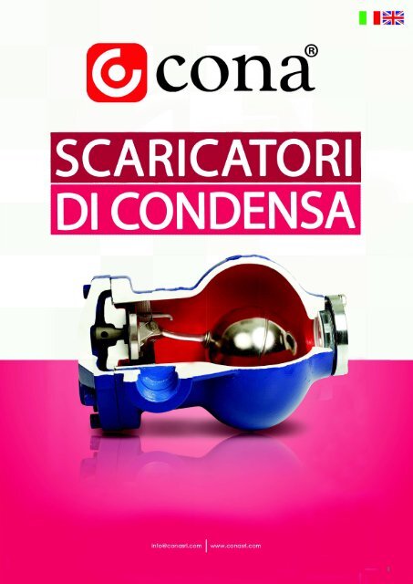
SCARICATORI DI CONDENSA / STEAM TRAPS<br />
SCARICATORI DI CONDENSA<br />
Al fine <strong>di</strong> ottenere la massima efficienza e durata delle linee <strong>di</strong> vapore e dei sistemi a<br />
vapore ad essi collegati è fondamentale effettuare una corretta scelta degli scaricatori<br />
<strong>di</strong> condensa.<br />
<strong>Scaricatori</strong> <strong>di</strong> condensa meccanici:<br />
Il funzionamento <strong>di</strong> uno scaricatore <strong>di</strong> condensa meccanico si basa sul movimento<br />
<strong>di</strong> parti mobili, in apertura o in chiusura, che hanno lo scopo <strong>di</strong> attivare la valvola. Gli<br />
scaricatori a galleggiante con valvola <strong>di</strong> sfiato termostatica utilizzano un galleggiante<br />
sferico che si solleva quando il livello <strong>di</strong> condensa nello scaricatore aumenta ed attiva<br />
così la valvola. I cambiamenti improvvisi <strong>di</strong> pressione non influiscono sul funzionamento<br />
dello scaricatore. Questa tipologia <strong>di</strong> scaricatori è utilizzata dove si rende necessario lo<br />
scarico continuo <strong>di</strong> condensa.<br />
<strong>Scaricatori</strong> <strong>di</strong> condensa termostatici:<br />
Gli scaricatori <strong>di</strong> condensa termostatici lavorano al variare della temperatura della<br />
condensa. Negli scaricatori <strong>di</strong> condensa termostatici l'aumento <strong>di</strong> volume dovuto alla<br />
vaporizzazione del liquido aumenta la pressione del vapore all'interno della capsula<br />
che, risultando successivamente maggiore della pressione dell'intero sistema, forza<br />
il <strong>di</strong>aframma ad estendersi verso la valvola e a chiuderla. Quando la temperatura<br />
<strong>di</strong>minuisce, <strong>di</strong>minuisce anche la pressione del vapore nella capsula, allentando il<br />
<strong>di</strong>aframma ed aprendo la valvola.<br />
<strong>Scaricatori</strong> <strong>di</strong> condensa termo<strong>di</strong>namici:<br />
Questo tipo <strong>di</strong> scaricatori opera in base alla <strong>di</strong>fferenza <strong>di</strong> pressione interna tra vapore<br />
e condensa. La condensa che arriva allo scaricatore solleva il <strong>di</strong>sco ed apre il foro,<br />
confluendo senza interruzione, spinta dalla pressione del vapore, al <strong>di</strong> sotto della<br />
condensa stessa.<br />
STEAM TRAPS<br />
In order to get maximum efficiency and service life from the steam lines and steam<br />
related systems, it is crucial to make the correct steam trap selection.<br />
Mechanical Steam Traps:<br />
Mechanical steam traps operation relies on the movement of open or closed floating<br />
parts to activate the valve. Float type steam traps with thermostatic air vent use a sealed<br />
spherical float which becomes buoyant when the condensate level in the trap rises<br />
and actuates the valve. It is unaffected by instantaneous pressure changing.<br />
This type of steam traps is used specially where prompt and continuous <strong>di</strong>scharge of<br />
condensate is necessary.<br />
Thermostatic Steam Traps:<br />
Thermostatic steam traps operate with the temperature changes of the condensate.<br />
Into thermostatic traps the increase in volume collected by the vaporization of liquid<br />
raises the vapour pressure inside the capsule that, becoming greater than the system<br />
pressure, forces the <strong>di</strong>aphragm to extend in the <strong>di</strong>rection of the valve and to close it.<br />
As the temperature reduces, the vapour pressure in the capsule reduces itself and makes<br />
<strong>di</strong>aphragm relax and open the valve.<br />
Thermodynamic Steam Traps:<br />
This type of steam traps operate by the internal pressure <strong>di</strong>fference of the steam and<br />
the condensate. This one raises the <strong>di</strong>sc, opens the orifice and flows continuously by<br />
the help of the steam pressure which is behind the condensate through the <strong>di</strong>scharge<br />
orifice.<br />
4
SIMBOLI PER LE CARATTERISTICHE E PER UNA RAPIDA SCELTA DEL PRODOTTO/ SYMBOLS FOR<br />
PRODUCT FEATURES AND QUICK SELECTION<br />
<strong>Scaricatori</strong> <strong>di</strong><br />
condensa a galleggiante<br />
/ Float type<br />
steam traps<br />
<strong>Scaricatori</strong> <strong>di</strong><br />
condensa termo<strong>di</strong>namici<br />
/ Thermodynamic<br />
steam traps<br />
<strong>Scaricatori</strong> <strong>di</strong> condensa<br />
termostatici /<br />
Thermostatic steam<br />
traps<br />
Pressione Massima<br />
del Prodotto/ Max.<br />
Product Pressure<br />
Connessione<br />
Filettata / Threaded<br />
Connection<br />
<strong>Condensa</strong> /<br />
<strong>Condensa</strong>te<br />
Standard Flangia /<br />
Flange Standard<br />
Standard Flangia /<br />
Flange Standard<br />
Temperatura<br />
Massima del<br />
Prodotto / Max.<br />
Product Temperature<br />
Installazione orizzontale<br />
/ Horizontal<br />
installation<br />
Installazione verticale<br />
/ Vertical installation<br />
Installazione in entrambe<br />
le <strong>di</strong>rezioni /<br />
Installation on both<br />
<strong>di</strong>rections<br />
5
SCARICATORI DI CONDENSA / STEAM TRAPS<br />
SCARICATORI DI CONDENSA MECCANICI / MECHANICAL STEAM TRAPSu SK-50<br />
SCARICATORE A GALLEGGIANTE CON VALVOLA TERMOSTATICA / FLOAT TYPE STEAM TRAP<br />
WITH AIR VENT<br />
Un galleggiante, tramite un semplice meccanismo a leva, apre o<br />
chiude la valvola a seconda del livello <strong>di</strong> condensa all’interno dello<br />
scaricatore. L’apertura è proporzionale al tasso <strong>di</strong> condensa e<br />
non è infl uenzata da rapi<strong>di</strong> cambiamenti <strong>di</strong> pressione. Questo tipo<br />
<strong>di</strong> scaricatori è utilizzato prevalentemente nei sistemi in cui si rende<br />
necessario uno scarico <strong>di</strong> condensa continuo.<br />
In questi casi gli scaricatori a galleggiante sono il prodotto ideale<br />
da utilizzare in associazione a sistemi <strong>di</strong> controllo automatico che<br />
provvedano ad un opportuno trasferimento <strong>di</strong> calore.<br />
Applicazioni tipiche:<br />
- Scambiatori <strong>di</strong> calore<br />
- Batterie <strong>di</strong> riscaldamento<br />
- Serbatoi<br />
- Vasche<br />
- Cilindri <strong>di</strong> essiccazione<br />
- Forni<br />
Installazione:<br />
Lo scaricatore deve essere installato con il braccio galleggiante su<br />
piano orizzontale così da permettere al galleggiante stesso <strong>di</strong> salire<br />
e scendere verticalmente rispetto al corpo dello scaricatore.<br />
Through a simple lever mechanism a fl oat opens or closes the valve<br />
accor<strong>di</strong>ng to the condensate level inside the trap. The opening is<br />
proportional to condensate rate. It is unaffected by instantaneous<br />
pressure changes. This type of steam traps is used specially where<br />
prompt and continuous <strong>di</strong>scharge of condensate is necessary.<br />
For such cases fl oat traps are the ideal traps as well as automatically<br />
control systems to provide adequate heat transfer.<br />
Typical applications:<br />
- Heat exchangers<br />
- Heating batteries<br />
- Tanks<br />
- Pans<br />
- Drying cylinders<br />
- Ovens<br />
Installation:<br />
The steam trap must be fi tted with the fl oat arm in horizontal plane<br />
so that the fl oat rises and falls vertically in the body.<br />
Con<strong>di</strong>zioni operative / Operating con<strong>di</strong>tions<br />
Pressione massima ammissibile PMA /<br />
Max. allowable pressure PMA<br />
[bar]<br />
Temperatura massima ammissibile TMA /<br />
Max. allowable temperature TMA<br />
[°C]<br />
Pressione massima <strong>di</strong> esercizio PMO /<br />
Max. operating pressure PMO<br />
[bar]<br />
Pressione <strong>di</strong>fferenziale massima PMD /<br />
Max. <strong>di</strong>fferential pressure PMD<br />
[bar]<br />
Temperatura massima <strong>di</strong> esercizio TMO /<br />
Max. operating temperature TMO<br />
[°C]<br />
Corpo in ghisa /<br />
Cast iron body<br />
Corpo in acciaio fuso<br />
/ Cast steel body<br />
25 40<br />
300 400<br />
16 32<br />
4,5 - 10 - 14 4,5 - 10 - 14<br />
250 400<br />
Connessioni /<br />
Connections<br />
Dimensioni /<br />
Sizes<br />
[mm]<br />
Pesi / Weights<br />
[Kg]<br />
Pesi / Weights<br />
Flangiato /<br />
Flanged<br />
Filettato /<br />
Threaded<br />
25 - 32 - 40 - 50 1” - 1”1/4 - 1”1/2 - 2”<br />
8,3 - 20,8 - 21,8 - 33 6,8 - 16,8 - 17,6 - 22<br />
Connessioni / Connections<br />
Filettato / Threaded<br />
NPT (ANSI BI 20.1)<br />
BSP (BS 21)<br />
Flangiato / Flanged DIN 2533<br />
6<br />
I prodotti CONA sono soggetti ad alterazioni tecniche derivanti dal processo <strong>di</strong> produzione.
SK-50 (1”)<br />
Curva rossa / Red chart ΔP = 14 bar<br />
Curva blu / Blue chart ΔP = 10 bar<br />
Curva nera / Black chart ΔP = 4,5 bar<br />
Parte nr. /<br />
Part no.<br />
Nome / Name<br />
Lista componenti / Parts list<br />
Materiale / Material<br />
1 Corpo / Body Ghisa sferoidale GGG 40.3 o Acciaio forgiato GSC 25 / Ductile iron GGG 40.3 or Cast steel GSC 25<br />
2 Coperchio / Cover Ghisa sferoidale GGG 40.3 o Acciaio forgiato GSC 25 / Ductile iron GGG 40.3 or Cast steel GSC 25<br />
3 Capsula termostatica / Thermostatic capsule Acciaio inox / Stainless steel<br />
4 Sede dell’unità termostatica / Air vent seat Acciaio inox AISI 304 / Stainless steel AISI 304<br />
5 Sede del galleggiante / Float seat Acciaio inox AISI 304 / Stainless steel AISI 304<br />
6 Sfera dell’otturatore / Main valve (ball) Acciaio inox AISI 440 C/ Stainless steel AISI 440 C<br />
7 Leva del galleggiante / Float lever Acciaio inox AISI 304 / Stainless steel AISI 304<br />
8 Galleggiante / Float Acciaio inox AISI 304 / Stainless steel AISI 304<br />
Flangiati / Flanged<br />
Co<strong>di</strong>ce / Code<br />
Diametro / Size<br />
A 1<br />
B C D Nr. Fori /<br />
[mm] [mm] [mm] [mm] No. Holes<br />
ΔP=4,5 bar ΔP=10 bar ΔP=14 bar<br />
DN25 210 116,5 78 208 4 703200202006 703200202007 703200202008<br />
Filettati / Threaded<br />
Co<strong>di</strong>ce / Code<br />
Diametro / Size<br />
A B C D E<br />
[mm] [mm] [mm] [mm] [mm]<br />
ΔP=4,5 bar ΔP=10 bar ΔP=14 bar<br />
1” 120 116,5 78 208 234,5 703200201006 703200201007 703200201008<br />
I prodotti CONA sono soggetti ad alterazioni tecniche derivanti dal processo <strong>di</strong> produzione.<br />
7
SCARICATORI DI CONDENSA / STEAM TRAPS<br />
SK-50 (1”1/4 - 2”)<br />
Curva rossa / Red chart ΔP = 14 bar<br />
Curva blu / Blue chart ΔP = 10 bar<br />
Curva nera / Black chart ΔP = 4,5 bar<br />
Parte nr. /<br />
Part no.<br />
Nome / Name<br />
Lista componenti / Parts list<br />
Materiale / Material<br />
1 Corpo / Body Ghisa sferoidale GGG 40.3 o Acciaio forgiato GSC 25 / Ductile iron GGG 40.3 or Cast steel GSC 25<br />
2 Coperchio / Cover Ghisa sferoidale GGG 40.3 o Acciaio forgiato GSC 25 / Ductile iron GGG 40.3 or Cast steel GSC 25<br />
3 Capsula termostatica / Thermostatic capsule Acciaio inox / Stainless steel<br />
4 Sede dell’unità termostatica / Air vent seat Acciaio inox AISI 304 / Stainless steel AISI 304<br />
5 Sede del galleggiante / Float seat Acciaio inox AISI 304 / Stainless steel AISI 304<br />
6 Sfera dell’otturatore / Main valve (ball) Acciaio inox AISI 440 C/ Stainless steel AISI 440 C<br />
7 Leva del galleggiante / Float lever Acciaio inox AISI 304 / Stainless steel AISI 304<br />
8 Galleggiante / Float Acciaio inox AISI 304 / Stainless steel AISI 304<br />
Flangiati / Flanged<br />
Co<strong>di</strong>ce / Code<br />
8<br />
Diametro / Size<br />
A 1<br />
B C 1<br />
D 1 Nr. Fori /<br />
[mm] [mm] [mm] [mm] No. Holes<br />
ΔP=4,5 bar ΔP=10 bar ΔP=14 bar<br />
DN32 320 130 108 242 4 703200202009 703200202010 703200202011<br />
DN40 320 138 108 242 4 703200202012 703200202013 703200202014<br />
DN50 320 138 122 250 4 703200202015 703200202016 703200202017<br />
Filettati / Threaded<br />
Co<strong>di</strong>ce / Code<br />
Diametro / Size<br />
A B C D E<br />
[mm] [mm] [mm] [mm] [mm]<br />
ΔP=4,5 bar ΔP=10 bar ΔP=14 bar<br />
1”1/4 270 130 108 238 270 703200201009 703200201010 703200201011<br />
1”1/2 270 138 108 238 270 703200201012 703200201013 703200201014<br />
2” 300 138 125 250 270 703200201015 703200201016 703200201017<br />
I prodotti CONA sono soggetti ad alterazioni tecniche derivanti dal processo <strong>di</strong> produzione.
SCARICATORI DI CONDENSA MECCANICI / MECHANICAL STEAM TRAPSu SK-51/SK-51C*<br />
SCARICATORE A GALLEGGIANTE CON VALVOLA TERMOSTATICA / FLOAT TYPE STEAM TRAP<br />
WITH AIR VENT<br />
Un galleggiante, tramite un semplice meccanismo a leva, apre o<br />
chiude la valvola a seconda del livello <strong>di</strong> condensa all’interno dello<br />
scaricatore. L’apertura è proporzionale al tasso <strong>di</strong> condensa e<br />
non è infl uenzata da rapi<strong>di</strong> cambiamenti <strong>di</strong> pressione. Questo tipo<br />
<strong>di</strong> scaricatori è utilizzato prevalentemente nei sistemi in cui si rende<br />
necessario uno scarico <strong>di</strong> condensa continuo. In questi casi, gli scaricatori<br />
a galleggiante sono il prodotto ideale da utilizzare in associazione<br />
a sistemi <strong>di</strong> controllo automatico che provvedano ad un<br />
opportuno trasferimento <strong>di</strong> calore.<br />
Applicazioni tipiche:<br />
- Scambiatori <strong>di</strong> calore<br />
- Batterie <strong>di</strong> riscaldamento<br />
- Serbatoi<br />
- Vasche<br />
- Cilindri <strong>di</strong> essiccazione<br />
- Forni<br />
Installazione:<br />
Il coperchio può essere installato sia orizzontalmente che verticalmente.<br />
Con<strong>di</strong>zioni operative / Operating con<strong>di</strong>tions<br />
Pressione massima ammissibile PMA /<br />
Max. allowable pressure PMA<br />
[bar]<br />
Temperatura massima ammissibile TMA /<br />
Max. allowable temperature TMA<br />
[°C]<br />
Pressione massima <strong>di</strong> esercizio PMO /<br />
Max. operating pressure PMO<br />
[bar]<br />
Pressione <strong>di</strong>fferenziale massima PMD /<br />
Max. <strong>di</strong>fferential pressure PMD<br />
[bar]<br />
Temperatura massima <strong>di</strong> esercizio TMO /<br />
Max. operating temperature TMO<br />
[°C]<br />
Corpo in ghisa /<br />
Cast iron body<br />
Through a simple lever mechanism a fl oat opens or closes the valve<br />
accor<strong>di</strong>ng to the condensate level inside the trap. The opening is<br />
proportional to condensate rate. It is unaffected by instantaneous<br />
pressure changes. This type of steam traps is used specially where<br />
prompt and continuous <strong>di</strong>scharge of condensate is necessary.<br />
For such cases fl oat traps are the ideal traps as well as automatically<br />
control systems to provide adequate heat transfer.<br />
Typical applications:<br />
- Heat exchangers<br />
- Heating batteries<br />
- Tanks<br />
- Pans<br />
- Drying cylinders<br />
- Ovens<br />
Installation:<br />
Cover part can be arranged accor<strong>di</strong>ng to horizontal or vertical installation<br />
type.<br />
Corpo in acciaio fuso<br />
/ Cast steel body<br />
25 40<br />
300 400<br />
16 32<br />
4,5 - 10 - 14 4,5 - 10 - 14<br />
250 400<br />
* SK-51C: L’unità termostatica può essere <strong>di</strong>sabilitata con l’asta <strong>di</strong> bilanciamento /<br />
The thermostatic unit can be <strong>di</strong>sabled by balance rod.<br />
Connessioni /<br />
Connections<br />
Dimensioni /<br />
Sizes<br />
[mm]<br />
Pesi / Weights<br />
[Kg]<br />
Pesi / Weights<br />
Flangiato /<br />
Flanged<br />
Filettato /<br />
Threaded<br />
15 - 20 - 25 1/2” - 3/4” - 1”<br />
4,05 - 4,8 - 7,1 3,2 - 3,2 - 4,7<br />
Connessioni / Connections<br />
Filettato / Threaded<br />
NPT (ANSI BI 20.1)<br />
BSP (BS 21)<br />
Flangiato / Flanged DIN 2533<br />
I prodotti CONA sono soggetti ad alterazioni tecniche derivanti dal processo <strong>di</strong> produzione.<br />
9
SCARICATORI DI CONDENSA / STEAM TRAPS<br />
Curva rossa / Red chart ΔP = 14 bar<br />
Curva blu / Blue chart ΔP = 10 bar<br />
Curva nera / Black chart ΔP = 4,5 bar<br />
Parte nr. /<br />
Part no.<br />
Nome / Name<br />
Lista componenti / Parts list<br />
Materiale / Material<br />
1 Corpo / Body Ghisa sferoidale GGG 40.3 o Acciaio forgiato GSC 25 / Ductile iron GGG 40.3 or Cast steel GSC 25<br />
2 Coperchio / Cover Ghisa sferoidale GGG 40.3 o Acciaio forgiato GSC 25 / Ductile iron GGG 40.3 or Cast steel GSC 25<br />
3 Capsula termostatica / Thermostatic capsule Acciaio inox / Stainless steel<br />
4 Sede dell’unità termostatica / Air vent seat Acciaio inox AISI 304 / Stainless steel AISI 304<br />
5 Sede del galleggiante / Float seat Acciaio inox AISI 304 / Stainless steel AISI 304<br />
6 Sfera dell’otturatore / Main valve (ball) Acciaio inox AISI 440 C/ Stainless steel AISI 440 C<br />
7 Leva del galleggiante / Float lever Acciaio inox AISI 304 / Stainless steel AISI 304<br />
8 Galleggiante / Float Acciaio inox AISI 304 / Stainless steel AISI 304<br />
Flangiati / Flanged<br />
Co<strong>di</strong>ce / Code<br />
10<br />
Diametro / Size<br />
A B C K Nr. Fori /<br />
[mm] [mm] [mm] [mm] No. Holes<br />
ΔP=4,5 bar ΔP=10 bar ΔP=14 bar<br />
DN15 150 108 68 150 4 703200102000 703200102001 703200102002<br />
DN20 150 108 68 150 4 703200102003 703200102004 703200102005<br />
DN25 160 108 107 167 4 703200102010 703200102011 703200102012<br />
Filettati / Threaded<br />
Co<strong>di</strong>ce / Code<br />
Diametro / Size<br />
D B C K<br />
[mm] [mm] [mm] [mm]<br />
ΔP=4,5 bar ΔP=10 bar ΔP=14 bar<br />
1/2” 122 108 68 150 703200101000 703200101001 703200101002<br />
3/4” 122 108 68 150 703200101003 703200101004 703200101005<br />
1” 145 108 107 167 703200101006 703200101007 703200101008<br />
I prodotti CONA sono soggetti ad alterazioni tecniche derivanti dal processo <strong>di</strong> produzione.
SCARICATORI DI CONDENSA MECCANICI / MECHANICAL STEAM TRAPSu SK-55<br />
SCARICATORE A GALLEGGIANTE CON VALVOLA TERMOSTATICA / FLOAT TYPE STEAM TRAP<br />
WITH AIR VENT<br />
Un galleggiante, tramite un semplice meccanismo a leva, apre o<br />
chiude la valvola a seconda del livello <strong>di</strong> condensa all’interno dello<br />
scaricatore. L’apertura è proporzionale al tasso <strong>di</strong> condensa e<br />
non è infl uenzata da rapi<strong>di</strong> cambiamenti <strong>di</strong> pressione. Questo tipo<br />
<strong>di</strong> scaricatori è utilizzato prevalentemente nei sistemi in cui si rende<br />
necessario uno scarico <strong>di</strong> condensa continuo.<br />
In questi casi gli scaricatori a galleggiante sono il prodotto ideale<br />
da utilizzare in associazione a sistemi <strong>di</strong> controllo automatico che<br />
provvedano ad un opportuno trasferimento <strong>di</strong> calore.<br />
Applicazioni tipiche:<br />
- Scambiatori <strong>di</strong> calore<br />
- Batterie <strong>di</strong> riscaldamento<br />
- Serbatoi<br />
- Vasche<br />
- Cilindri <strong>di</strong> essiccazione<br />
- Forni<br />
Installazione:<br />
Lo scaricatore deve essere installato con il braccio galleggiante su<br />
piano orizzontale così da permettere al galleggiante stesso <strong>di</strong> salire<br />
e scendere verticalmente rispetto al corpo dello scaricatore.<br />
Con<strong>di</strong>zioni operative /<br />
Operating con<strong>di</strong>tions<br />
Pressione massima ammissibile PMA /<br />
Max. allowable pressure PMA<br />
[bar]<br />
Temperatura massima ammissibile TMA /<br />
Max. allowable temperature TMA<br />
[°C]<br />
Pressione massima <strong>di</strong> esercizio PMO /<br />
Max. operating pressure PMO<br />
[bar]<br />
Pressione <strong>di</strong>fferenziale massima PMD /<br />
Max. <strong>di</strong>fferential pressure PMD<br />
[bar]<br />
Temperatura massima <strong>di</strong> esercizio TMO /<br />
Max. operating temperature TMO<br />
[°C]<br />
25<br />
300<br />
16<br />
4,5 - 10 - 14<br />
250<br />
Through a simple lever mechanism a fl oat opens or closes the valve<br />
accor<strong>di</strong>ng to the condensate level inside the trap. The opening is<br />
proportional to condensate rate. It is unaffected by instantaneous<br />
pressure changes. This type of steam traps is used specially where<br />
prompt and continuous <strong>di</strong>scharge of condensate is necessary.<br />
For such cases fl oat traps are the ideal traps as well as automatically<br />
control systems to provide adequate heat transfer.<br />
Typical applications:<br />
- Heat exchangers<br />
- Heating batteries<br />
- Tanks<br />
- Pans<br />
- Drying cylinders<br />
- Ovens<br />
Installation:<br />
The steam trap must be fi tted with the fl oat arm in horizontal plane<br />
so that the fl oat rises and falls vertically in the body.<br />
Connessioni /<br />
Connections<br />
Dimensioni /<br />
Sizes<br />
[mm]<br />
Pesi / Weights<br />
[Kg]<br />
Pesi / Weights<br />
Flangiato /<br />
Flanged<br />
Filettato /<br />
Threaded<br />
32 - 40 - 50 1”1/4 - 1”1/2 - 2”<br />
20,8 - 21,8 - 33 16,8 - 17,6 - 22<br />
Connessioni / Connections<br />
Filettato / Threaded<br />
NPT (ANSI BI 20.1)<br />
BSP (BS 21)<br />
Flangiato / Flanged DIN 2533<br />
I prodotti CONA sono soggetti ad alterazioni tecniche derivanti dal processo <strong>di</strong> produzione.<br />
11
SCARICATORI DI CONDENSA / STEAM TRAPS<br />
Curva rossa / Red chart ΔP = 14 bar<br />
Curva blu / Blue chart ΔP = 10 bar<br />
Curva nera / Black chart ΔP = 4,5 bar<br />
Parte nr. /<br />
Part no.<br />
Nome / Name<br />
Lista componenti / Parts list<br />
Materiale / Material<br />
1 Corpo / Body Ghisa sferoidale GGG 40.3 o acciaio fuso GSC 25/ Ductile iron GGG 40.3 or cast steel GSC 25<br />
2 Coperchio / Cover Ghisa sferoidale GGG 40.3 o acciaio fuso GSC 25/ Ductile iron GGG 40.3 or cast steel GSC 25<br />
3 Capsula termostatica / Thermostatic capsule Acciaio inox AISI 304 / Stainless steel AISI 304<br />
4 Sede dell’unità termostatica / Air vent seat Acciaio inox AISI 304 / Stainless steel AISI 304<br />
5 Leva del galleggiante / Float lever Acciaio inox AISI 304 / Stainless steel AISI 304<br />
6 Galleggiante / Float Acciaio inox AISI 304 / Stainless steel AISI 304<br />
Flangiati / Flanged<br />
Co<strong>di</strong>ce / Code<br />
12<br />
Diametro / Size<br />
A1 B C1 D1 Nr. Fori /<br />
[mm] [mm] [mm] [mm] No. Holes<br />
ΔP=4,5 bar ΔP=10 bar ΔP=14 bar<br />
DN32 320 130 108 242 Ø18x4 703200202032 703200202031 703200202033<br />
DN40 320 130 108 242 Ø18x4 703200202035 703200202034 703200202036<br />
DN50 320 138 122 250 Ø18x4 703200202038 703200202037 703200202039<br />
Filettati / Threaded<br />
Co<strong>di</strong>ce / Code<br />
Diametro / Size<br />
A B C D<br />
[mm] [mm] [mm] [mm]<br />
ΔP=4,5 bar ΔP=10 bar ΔP=14 bar<br />
1”1/4 270 130 108 238 703200201082 703200201081 703200201083<br />
1”1/2 270 130 108 238 703200201085 703200201084 703200201086<br />
2” 300 138 125 250 703200201088 703200201087 703200201089<br />
I prodotti CONA sono soggetti ad alterazioni tecniche derivanti dal processo <strong>di</strong> produzione.
SCARICATORI DI CONDENSA MECCANICI / MECHANICAL STEAM TRAPSu SK-55L<br />
SCARICATORE A GALLEGGIANTE CON VALVOLA TERMOSTATICA ED ISPEZIONE / FLOAT TYPE<br />
STEAM TRAP WITH AIR VENT AND SIGHT GLASS<br />
Un galleggiante, tramite un semplice meccanismo a leva, apre o<br />
chiude la valvola a seconda del livello <strong>di</strong> condensa all’interno dello<br />
scaricatore. L’apertura è proporzionale al tasso <strong>di</strong> condensa e<br />
non è infl uenzata da rapi<strong>di</strong> cambiamenti <strong>di</strong> pressione. Questo tipo<br />
<strong>di</strong> scaricatori è utilizzato prevalentemente nei sistemi in cui si rende<br />
necessario uno scarico <strong>di</strong> condensa continuo.<br />
In questi casi gli scaricatori a galleggiante sono il prodotto ideale<br />
da utilizzare in associazione a sistemi <strong>di</strong> controllo automatico che<br />
provvedano ad un opportuno trasferimento <strong>di</strong> calore.<br />
Applicazioni tipiche:<br />
- Scambiatori <strong>di</strong> calore<br />
- Batterie <strong>di</strong> riscaldamento<br />
- Serbatoi<br />
- Vasche<br />
- Cilindri <strong>di</strong> essiccazione<br />
- Forni<br />
Installazione:<br />
Lo scaricatore deve essere installato con il braccio galleggiante su<br />
piano orizzontale così da permettere al galleggiante stesso <strong>di</strong> salire<br />
e scendere verticalmente rispetto al corpo dello scaricatore.<br />
Con<strong>di</strong>zioni operative /<br />
Operating con<strong>di</strong>tions<br />
Pressione massima ammissibile PMA /<br />
Max. allowable pressure PMA<br />
[bar]<br />
Temperatura massima ammissibile TMA /<br />
Max. allowable temperature TMA<br />
[°C]<br />
Pressione massima <strong>di</strong> esercizio PMO /<br />
Max. operating pressure PMO<br />
[bar]<br />
Pressione <strong>di</strong>fferenziale massima PMD /<br />
Max. <strong>di</strong>fferential pressure PMD<br />
[bar]<br />
Temperatura massima <strong>di</strong> esercizio TMO /<br />
Max. operating temperature TMO<br />
[°C]<br />
25<br />
300<br />
16<br />
4,5 - 10 - 14<br />
250<br />
Through a simple lever mechanism a fl oat opens or closes the valve<br />
accor<strong>di</strong>ng to the condensate level inside the trap. The opening is<br />
proportional to condensate rate. It is unaffected by instantaneous<br />
pressure changes. This type of steam traps is used specially where<br />
prompt and continuous <strong>di</strong>scharge of condensate is necessary.<br />
For such cases fl oat traps are the ideal traps as well as automatically<br />
control systems to provide adequate heat transfer.<br />
Typical applications:<br />
- Heat exchangers<br />
- Heating batteries<br />
- Tanks<br />
- Pans<br />
- Drying cylinders<br />
- Ovens<br />
Installation:<br />
The steam trap must be fi tted with the fl oat arm in horizontal plane<br />
so that it rises and falls vertically in the body.<br />
Connessioni /<br />
Connections<br />
Dimensioni /<br />
Sizes<br />
[mm]<br />
Pesi / Weights<br />
[Kg]<br />
Pesi / Weights<br />
Flangiato /<br />
Flanged<br />
Filettato /<br />
Threaded<br />
32 - 40 - 50 1”1/4 - 1”1/2 - 2”<br />
20,8 - 21,8 - 33 16,8 - 17,6 - 22<br />
Connessioni / Connections<br />
Filettato / Threaded<br />
NPT (ANSI BI 20.1)<br />
BSP (BS 21)<br />
Flangiato / Flanged DIN 2533<br />
I prodotti CONA sono soggetti ad alterazioni tecniche derivanti dal processo <strong>di</strong> produzione.<br />
13
SCARICATORI DI CONDENSA / STEAM TRAPS<br />
Curva rossa / Red chart ΔP = 14 bar<br />
Curva blu / Blue chart ΔP = 10 bar<br />
Curva nera / Black chart ΔP = 4,5 bar<br />
Parte nr. /<br />
Part no.<br />
Nome / Name<br />
Lista componenti / Parts list<br />
Materiale / Material<br />
1 Corpo / Body Ghisa sferoidale GGG 40.3/ Ductile iron GGG 40.3<br />
2 Galleggiante / Float Acciaio inox AISI 304 / Stainless steel AISI 304<br />
3 Sfera del galleggiante+Leva/Float Sphere+Lever Acciaio inox AISI 316 / Stainless steel AISI 316<br />
4 Guarnizione della guida / Guide gasket Acciaio inox AISI 304 / Stainless steel AISI 304<br />
5 Schermo del filtro / Strainer screen Acciaio inox AISI 304 / Stainless steel AISI 304<br />
6 Unità termostatica / Thermostatic unit Acciaio inox AISI 304/ Stainless steel AISI 304<br />
7 Guarnizione del coperchio / Cover gasket Grafite pura / Pure graphite<br />
8 Coperchio / Cover Ghisa sferoidale GGG 40.3/ Ductile iron GGG 40.3<br />
Flangiati / Flanged<br />
Co<strong>di</strong>ce / Code<br />
14<br />
Diametro / Size<br />
D ØK Øg b A B ØD1 L Nr. Fori /<br />
[mm] [mm] [mm] [mm] [mm] [mm] [mm] [mm] No. Holes<br />
ΔP=4,5 bar ΔP=10 bar ΔP=14 bar<br />
DN32 140 100 78 20 284,5 170 190 230 Ø18x4 703200202022 703200202021 703200202023<br />
DN40 150 110 86 20 284,5 170 190 230 Ø18x4 703200202025 703200202024 703200202026<br />
DN50 165 125 102 20 296,5 176 230 230 Ø18x4 703200202028 703200202027 703200202029<br />
Filettati / Threaded<br />
Co<strong>di</strong>ce / Code<br />
Diametro / Size<br />
A B ØD ØD1 L<br />
[mm] [mm] [mm] [mm] [mm]<br />
ΔP=4,5 bar ΔP=10 bar ΔP=14 bar<br />
1”1/4 284,5 170 190 68 230 703200201072 703200201071 703200201073<br />
1”1/2 284,5 170 190 68 230 703200201075 703200201074 703200201076<br />
2” 284,5 170 230 80 230 703200201078 703200201077 703200201079<br />
I prodotti CONA sono soggetti ad alterazioni tecniche derivanti dal processo <strong>di</strong> produzione.
SCARICATORI DI CONDENSA MECCANICI / MECHANICAL STEAM TRAPSu SK-61/SK-61C*<br />
SCARICATORE A GALLEGGIANTE CON VALVOLA TERMOSTATICA / FLOAT TYPE STEAM TRAP<br />
WITH AIR VENT<br />
Un galleggiante, tramite un semplice meccanismo a leva, apre o<br />
chiude la valvola a seconda del livello <strong>di</strong> condensa all’interno dello<br />
scaricatore. L’apertura è proporzionale al tasso <strong>di</strong> condensa e<br />
non è infl uenzata da rapi<strong>di</strong> cambiamenti <strong>di</strong> pressione. Questo tipo<br />
<strong>di</strong> scaricatori è utilizzato prevalentemente nei sistemi in cui si rende<br />
necessario uno scarico <strong>di</strong> condensa continuo.<br />
In questi casi gli scaricatori a galleggiante sono il prodotto ideale<br />
da utilizzare in associazione a sistemi <strong>di</strong> controllo automatico che<br />
provvedano ad un opportuno trasferimento <strong>di</strong> calore.<br />
Applicazioni tipiche:<br />
- Scambiatori <strong>di</strong> calore<br />
- Batterie <strong>di</strong> riscaldamento<br />
- Serbatoi<br />
- Vasche<br />
- Cilindri <strong>di</strong> essiccazione<br />
- Forni<br />
Installazione:<br />
Il coperchio può essere installato sia orizzontalmente che verticalmente.<br />
Con<strong>di</strong>zioni operative /<br />
Operating con<strong>di</strong>tions<br />
Pressione massima ammissibile PMA /<br />
Max. allowable pressure PMA<br />
[bar]<br />
Temperatura massima ammissibile TMA /<br />
Max. allowable temperature TMA<br />
[°C]<br />
Pressione massima <strong>di</strong> esercizio PMO /<br />
Max. operating pressure PMO<br />
[bar]<br />
Pressione <strong>di</strong>fferenziale massima PMD /<br />
Max. <strong>di</strong>fferential pressure PMD<br />
[bar]<br />
Temperatura massima <strong>di</strong> esercizio TMO /<br />
Max. operating temperature TMO<br />
[°C]<br />
25<br />
300<br />
25<br />
4,5 - 10 - 14<br />
Through a simple lever mechanism a fl oat opens or closes the valve<br />
accor<strong>di</strong>ng to the condensate level inside the trap. The opening is<br />
proportional to condensate rate. It is unaffected by instantaneous<br />
pressure changes. This type of steam traps is used specially where<br />
prompt and continuous <strong>di</strong>scharge of condensate is necessary.<br />
For such cases fl oat traps are the ideal traps as well as automatically<br />
control systems to provide adequate heat transfer.<br />
Typical applications:<br />
- Heat exchangers<br />
- Heating batteries<br />
- Tanks<br />
- Pans<br />
- Drying cylinders<br />
- Ovens<br />
* SK-61C: L’unità termostatica può essere <strong>di</strong>sabilitata con l’asta <strong>di</strong> bilanciamento /<br />
The thermostatic unit can be <strong>di</strong>sabled by balance rod.<br />
250<br />
Installation:<br />
Cover part can be arranged accor<strong>di</strong>ng to horizontal or vertical<br />
type.<br />
Connessioni /<br />
Connections<br />
Dimensioni /<br />
Sizes<br />
[mm]<br />
Pesi / Weights<br />
[Kg]<br />
Connessioni / Connections<br />
Filettato / Threaded<br />
Pesi / Weights<br />
Flangiato /<br />
Flanged<br />
NPT (ANSI BI 20.1)<br />
BSP (BS 21)<br />
Flangiato / Flanged DIN 2533<br />
Filettato /<br />
Threaded<br />
15 - 20 - 25 1/2” - 3/4” - 1”<br />
5,5 - 5,5 - 6,85 4,10 - 4,10 - 4,65<br />
I prodotti CONA sono soggetti ad alterazioni tecniche derivanti dal processo <strong>di</strong> produzione.<br />
15
SCARICATORI DI CONDENSA / STEAM TRAPS<br />
Curva rossa / Red chart ΔP = 14 bar<br />
Curva blu / Blue chart ΔP = 10 bar<br />
Curva nera / Black chart ΔP = 4,5 bar<br />
Parte nr. /<br />
Part no.<br />
Nome / Name<br />
Lista componenti / Parts list<br />
Materiale / Material<br />
1 Coperchio / Cover Acciaio inox AISI 316 / Stainless steel AISI 316<br />
2 Corpo / Body Acciaio inox AISI 316 / Stainless steel AISI 316<br />
3 Capsula termostatica / Thermostatic capsule Acciaio inox AISI 316 / Stainless steel AISI 316<br />
4 Sede dell’unità termostatica / Air vent seat Acciaio inox AISI 316 / Stainless steel AISI 316<br />
5 Sede del galleggiante / Float seat Acciaio inox AISI 316 / Stainless steel AISI 316<br />
6 Sfera dell’otturatore / Main valve (ball) Acciaio inox AISI 440 C/ Stainless steel AISI 440 C<br />
7 Leva del galleggiante / Float lever Acciaio inox AISI 316 / Stainless steel AISI 316<br />
8 Galleggiante / Float Acciaio inox AISI 316 / Stainless steel AISI 316<br />
Flangiati / Flanged<br />
Co<strong>di</strong>ce / Code<br />
16<br />
Diametro / Size<br />
A B C K Nr. Fori /<br />
[mm] [mm] [mm] [mm] No. Holes<br />
ΔP=4,5 bar ΔP=10 bar ΔP=14 bar<br />
DN15 150 108 68 150 4 703200105100 703200105101 703200105102<br />
DN20 150 108 68 150 4 703200105103 703200105104 703200105105<br />
DN25 160 108 107 167 4 703200105106 703200105107 703200105108<br />
Filettati / Threaded<br />
Co<strong>di</strong>ce / Code<br />
Diametro / Size<br />
D B C K<br />
[mm] [mm] [mm] [mm]<br />
ΔP=4,5 bar ΔP=10 bar ΔP=14 bar<br />
1/2” 122 108 68 150 703200105000 703200105001 703200105002<br />
3/4” 122 108 68 150 703200105003 703200105004 703200105005<br />
1” 145 108 107 167 703200105006 703200105007 703200105008<br />
I prodotti CONA sono soggetti ad alterazioni tecniche derivanti dal processo <strong>di</strong> produzione.
SCARICATORI DI CONDENSA MECCANICI / MECHANICAL STEAM TRAPSu SK-70<br />
SCARICATORE A GALLEGGIANTE CON VALVOLA TERMOSTATICA / FLOAT TYPE STEAM TRAP<br />
WITH AIR VENT<br />
Un galleggiante, tramite un semplice meccanismo a leva, apre o<br />
chiude la valvola a seconda del livello <strong>di</strong> condensa all’interno dello<br />
scaricatore. L’apertura è proporzionale al tasso <strong>di</strong> condensa e<br />
non è infl uenzata da rapi<strong>di</strong> cambiamenti <strong>di</strong> pressione. Questo tipo<br />
<strong>di</strong> scaricatori è utilizzato prevalentemente nei sistemi in cui si rende<br />
necessario uno scarico <strong>di</strong> condensa continuo.<br />
In questi casi gli scaricatori a galleggiante sono il prodotto ideale<br />
da utilizzare in associazione a sistemi <strong>di</strong> controllo automatico che<br />
provvedano ad un opportuno trasferimento <strong>di</strong> calore.<br />
Applicazioni tipiche:<br />
- Industria farmaceutica<br />
- Industria chimica<br />
- Industria alimentare<br />
- Scambiatori <strong>di</strong> calore<br />
- Batterie <strong>di</strong> riscaldamento<br />
- Serbatoi<br />
- Vasche<br />
- Cilindri <strong>di</strong> essiccazione<br />
- Forni.<br />
Installazione:<br />
Il coperchio può essere installato sia orizzontalmente che verticalmente.<br />
Through a simple lever mechanism a fl oat opens or closes the valve<br />
accor<strong>di</strong>ng to the condensate level inside the trap. The opening is<br />
proportional to condensate rate. It is unaffected by instantaneous<br />
pressure changes. This type of steam traps is used specially where<br />
prompt and continuous <strong>di</strong>scharge of condensate is necessary.<br />
For such cases fl oat traps are the ideal traps as well as automatically<br />
control systems to provide adequate heat transfer.<br />
Typical applications:<br />
- Pharmaceutical industry<br />
- Chemical industry<br />
- Food industry<br />
- Heat exchangers<br />
- Heating batteries<br />
- Tanks<br />
- Pans<br />
- Drying cylinders<br />
- Ovens<br />
Installation:<br />
Cover part can be arranged accor<strong>di</strong>ng to horizontal or vertical installation<br />
type.<br />
Con<strong>di</strong>zioni operative /<br />
Operating con<strong>di</strong>tions<br />
Pressione massima ammissibile PMA /<br />
Max. allowable pressure PMA<br />
[bar]<br />
Temperatura massima ammissibile TMA /<br />
Max. allowable temperature TMA<br />
[°C]<br />
Pressione massima <strong>di</strong> esercizio PMO /<br />
Max. operating pressure PMO<br />
[bar]<br />
Pressione <strong>di</strong>fferenziale massima PMD /<br />
Max. <strong>di</strong>fferential pressure PMD<br />
[bar]<br />
Temperatura massima <strong>di</strong> esercizio TMO /<br />
Max. operating temperature TMO<br />
[°C]<br />
25<br />
300<br />
25<br />
4,5 - 10 - 14<br />
250<br />
Connessioni /<br />
Connections<br />
Dimensioni /<br />
Sizes<br />
[mm]<br />
Pesi / Weights<br />
[Kg]<br />
Pesi / Weights<br />
Flangiato /<br />
Flanged<br />
Filettato /<br />
Threaded<br />
15 - 20 - 25 1/2” - 3/4” - 1”<br />
5,5 - 5,5 - 6,85 4,10 - 4,10 - 4,65<br />
Connessioni / Connections<br />
Filettato / Threaded<br />
NPT (ANSI BI 20.1)<br />
BSP (BS 21)<br />
Flangiato / Flanged DIN 2533<br />
I prodotti CONA sono soggetti ad alterazioni tecniche derivanti dal processo <strong>di</strong> produzione.<br />
17
SCARICATORI DI CONDENSA / STEAM TRAPS<br />
Curva rossa / Red chart ΔP = 14 bar<br />
Curva blu / Blue chart ΔP = 10 bar<br />
Curva nera / Black chart ΔP = 4,5 bar<br />
Parte nr. /<br />
Part no.<br />
Nome / Name<br />
Lista componenti / Parts list<br />
Materiale / Material<br />
1 Coperchio / Cover Acciaio fuso GSC 25 / Cast iron GSC 25<br />
2 Corpo / Body Acciaio fuso GSC 25 / Cast iron GSC 25<br />
3 Capsula termostatica / Thermostatic capsule Acciaio inox AISI 304 / Stainless steel AISI 304<br />
4 Sede dell’unità termostatica / Air vent seat Acciaio inox AISI 304 / Stainless steel AISI 304<br />
5 Sede del galleggiante / Float seat Acciaio inox AISI 304 / Stainless steel AISI 304<br />
6 Sfera dell’otturatore / Main valve (ball) Acciaio inox AISI 440 C/ Stainless steel AISI 440 C<br />
7 Leva del galleggiante / Float lever Acciaio inox AISI 304 / Stainless steel AISI 304<br />
8 Galleggiante / Float Acciaio inox AISI 304 / Stainless steel AISI 304<br />
Flangiati / Flanged<br />
Co<strong>di</strong>ce / Code<br />
18<br />
Diametro / Size<br />
A B C K Nr. Fori /<br />
[mm] [mm] [mm] [mm] No. Holes<br />
ΔP=4,5 bar ΔP=10 bar ΔP=14 bar<br />
DN15 150 108 68 150 4 703200105119 703200105120 703200105121<br />
DN20 150 108 68 150 4 703200105122 703200105123 703200105124<br />
DN25 160 108 107 167 4 703200105125 703200105126 703200105127<br />
Filettati / Threaded<br />
Co<strong>di</strong>ce / Code<br />
Diametro / Size<br />
D B C K<br />
[mm] [mm] [mm] [mm]<br />
ΔP=4,5 bar ΔP=10 bar ΔP=14 bar<br />
1/2” 122 108 68 150 703200105110 703200105111 703200105112<br />
3/4” 122 108 68 150 703200105113 703200105114 703200105115<br />
1” 145 108 107 167 703200105116 703200105117 703200105118<br />
I prodotti CONA sono soggetti ad alterazioni tecniche derivanti dal processo <strong>di</strong> produzione.
SCARICATORI DI CONDENSA MECCANICI / MECHANICAL STEAM TRAPSu SK-80<br />
SCARICATORE A GALLEGGIANTE CON VALVOLA TERMOSTATICA / FLOAT TYPE STEAM TRAP<br />
WITH AIR VENT<br />
Lo scaricatore <strong>di</strong> condensa SK-80 è utilizzato per scaricare la condensa<br />
con un sistema a galleggiante meccanico. Quando il sistema<br />
si mette in moto, la valvola termostatica si attiva e scarica l’aria nel<br />
sistema. Dopo questa fase, segue il vapore in entrata che chiude la<br />
valvola termostatica. Ad ogni modo, quando la condensa raggiunge<br />
lo scaricatore, il galleggiante si solleva, apre la valvola principale<br />
e scarica la condensa. Al termine dello scarico <strong>di</strong> condensa, dopo<br />
che il vapore è rientrato nello scaricatore, il galleggiante si abbassa<br />
e chiude la valvola.<br />
Installazione:<br />
Lo scaricatore SK-80 può essere utilizzato verticalmente purchè l’entrata<br />
sia posizionata in alto e l’uscita in basso. Può essere anche<br />
installato orizzontalmente in entrambe le <strong>di</strong>rezioni se non <strong>di</strong>versamente<br />
in<strong>di</strong>cato.<br />
The SK-80 fl oat steam trap is used for <strong>di</strong>scharging the condensate by<br />
a mechanical fl oat system. When the system starts up, the thermostatic<br />
air vent is activated and <strong>di</strong>scharges the air in the system. After<br />
this process, incoming steam will close the air vent. However when<br />
condensate reaches the steam trap, the fl oat rises, opens the main<br />
valve and <strong>di</strong>scharges the condensate. As soon as the condensate<br />
<strong>di</strong>scharge is completed and the steam reached into the trap, the<br />
fl oat goes down and closes the valve.<br />
Installation:<br />
SK-80 can be used vertically as long as the inlet stays up at the top<br />
and the outlet remains at the bottom. It can also be installed horizontally<br />
from right to left or the opposite way. If it is not in<strong>di</strong>cated<br />
<strong>di</strong>fferently in the order sheet, it will be assumed.<br />
Con<strong>di</strong>zioni operative /<br />
Operating con<strong>di</strong>tions<br />
Pressione massima <strong>di</strong> esercizio PMO /<br />
Max. operating pressure PMO<br />
[bar]<br />
Pressione <strong>di</strong>fferenziale massima PMD /<br />
Max. <strong>di</strong>fferential pressure PMD<br />
[bar]<br />
Temperatura massima <strong>di</strong> esercizio TMO /<br />
Max. operating temperature TMO<br />
[°C]<br />
16<br />
4,5 - 10 - 14<br />
250<br />
Connessioni /<br />
Connections<br />
Dimensioni /<br />
Sizes<br />
[mm]<br />
Pesi / Weights<br />
[Kg]<br />
Pesi / Weights<br />
Flangiato /<br />
Flanged<br />
32 - 40 - 50<br />
20,8 - 21,8 - 33<br />
Connessioni / Connections<br />
Flangiato / Flanged DIN 2533<br />
I prodotti CONA sono soggetti ad alterazioni tecniche derivanti dal processo <strong>di</strong> produzione.<br />
19
SCARICATORI DI CONDENSA / STEAM TRAPS<br />
Curva rossa / Red chart ΔP = 14 bar<br />
Curva blu / Blue chart ΔP = 10 bar<br />
Curva nera / Black chart ΔP = 4,5 bar<br />
Lista componenti / Parts list<br />
Parte nr. /<br />
Part no.<br />
Nome / Name<br />
Materiale / Material<br />
1 Corpo / Body Acciaio fuso GSC 25 / Cast iron GSC 25<br />
2 Coperchio / Cover Acciaio fuso GSC 25 / Cast iron GSC 25<br />
3 Capsula termostatica / Thermostatic capsule Acciaio inox AISI 304 / Stainless steel AISI 304<br />
4 Sede dell’unità termostatica / Air vent seat Acciaio inox AISI 304 / Stainless steel AISI 304<br />
5 Unità valvolare / Valve Assembly Acciaio inox AISI 304 / Stainless steel AISI 304<br />
6 Leva del galleggiante / Float lever Acciaio inox AISI 440 C/ Stainless steel AISI 440 C<br />
7 Galleggiante / Float Acciaio inox AISI 304 / Stainless steel AISI 304<br />
Flangiati / Flanged<br />
Co<strong>di</strong>ce / Code<br />
Diametro / Size<br />
A H1 H2 H L1 L2 L<br />
[mm] [mm] [mm] [mm] [mm] [mm] [mm]<br />
ΔP=4,5 bar ΔP=10 bar ΔP=14 bar<br />
DN25 116 - 116,5 195 303,5 246 116 703200203007 703200203008 703200203009<br />
DN32 190 237,5 107,5 207 385 315 230 703200203010 703200203011 703200203012<br />
DN40 190 237,5 107,5 207 390 315 230 703200203013 703200203014 703200203015<br />
DN50 220 262 124 230 417 335 230 703200203016 703200203017 703200203018<br />
20<br />
I prodotti CONA sono soggetti ad alterazioni tecniche derivanti dal processo <strong>di</strong> produzione.
SCARICATORI DI CONDENSA MECCANICI / MECHANICAL STEAM TRAPSu SK-40<br />
SCARICATORE A SFERA LIBERA / FREE FLOAT TYPE STEAM TRAP<br />
Questo tipo <strong>di</strong> scaricatori non contiene alcuna leva interna, l’unico<br />
componente mobile è il galleggiante stesso. Il galleggiante è realizzato<br />
in acciaio inossidabile con elevata qualità <strong>di</strong> superfi cie. La<br />
tolleranza globale del galleggiante è molto bassa.<br />
Funzionamento:<br />
Quando lo scaricatore è freddo, lo sfi ato si apre completamente<br />
per lo scarico continuo dell’aria iniziale. Quando la condensa fredda<br />
entra nello scaricatore, il galleggiante sale per consentire lo scarico<br />
<strong>di</strong> condensa dalla valvola e lo scarico sia dell’aria che della<br />
condensa dall’apertura.<br />
Dopo che tutta l’aria iniziale e la condensa fredda sono state scaricate,<br />
l’apparecchiatura che è collegata allo scaricatore raggiunge<br />
la temperatura <strong>di</strong> esercizio. In questo caso, la quantità <strong>di</strong><br />
condensa scende ma la temperatura sale. Il vapore entra nello scaricatore<br />
insieme alla condensa, la condensa calda riscalda lo sfi ato<br />
e lo chiude prima che il vapore possa fuoriuscire. Il galleggiante può<br />
adattarsi al tasso <strong>di</strong> fl usso della condensa. Al fi ne <strong>di</strong> evitare per<strong>di</strong>te<br />
<strong>di</strong> vapore, l’apertura dello scarico è tenuta sempre sotto un certo<br />
livello <strong>di</strong> acqua insieme con un sistema <strong>di</strong> tenuta metallica. Nei casi<br />
in cui lo scarico della condensa viene azionato dalle asciugatrici a<br />
cilindro, viene creata una linea <strong>di</strong> by-pass al <strong>di</strong> sopra del coperchio<br />
con lo scopo <strong>di</strong> prevenire il blocco del vapore. Lo scopo <strong>di</strong> questa<br />
linea è quello <strong>di</strong> scaricare il vapore prima della ripartenza del nuovo<br />
ciclo dello scaricatore.<br />
Installazione:<br />
Lo scaricatore deve essere posizionato con il galleggiante sul piano<br />
orizzontale in modo che quest’ultimo salga e scenda verticalmente<br />
all’interno dello scaricatore.<br />
This type of steam traps does not contain any lever inside, the only<br />
moving part is the fl oat itself. The fl oat is made of stainless steel with<br />
high surface quality. The global tolerance of the fl oat is very low.<br />
Operation:<br />
When the trap is cool, the air vent opens wide for continuously <strong>di</strong>scharging<br />
initial air. As cold condensate enters the trap, the fl oat rises<br />
to allow <strong>di</strong>scharge of condensate from valve port and both air and<br />
condensate from orifi ce.<br />
Once all initial air and cold condensate have been <strong>di</strong>scharged,<br />
the equipment which is connected to the steam trap reaches the<br />
operation temperature. In this case, the condensate amount drops<br />
but the temperature rises. Steam enters the trap along with condensate,<br />
hot condensate heats the air vent and closes before steam<br />
can escape. The fl oat can adjust itself accor<strong>di</strong>ng to the condensate<br />
fl ow rate. In order to prevent steam leakage, <strong>di</strong>scharge orifi ce<br />
is always kept under a certain level of water along with metal to<br />
metal sealing. In case the condensate <strong>di</strong>scharge is operated from<br />
cylinder driers, a by-pass line above the cover is created with the<br />
purpose of preventing the steam lock. The aim of this line is to <strong>di</strong>scharge<br />
the steam before the correct timing of steam trap entry.<br />
Installation:<br />
The steam trap must be fi tted with the fl oat in horizontal plane so<br />
that it rises and falls vertically in the body.<br />
Con<strong>di</strong>zioni operative /<br />
Operating con<strong>di</strong>tions<br />
Connessioni /<br />
Connections<br />
Flangiato /<br />
Flanged<br />
Filettato /<br />
Threaded<br />
Pressione massima <strong>di</strong> esercizio PMO /<br />
Max. operating pressure PMO<br />
[bar]<br />
16<br />
Dimensioni /<br />
Sizes<br />
[mm]<br />
15 - 20 -25 1/2” - 3/4” - 1”<br />
Pressione <strong>di</strong>fferenziale massima PMD /<br />
Max. <strong>di</strong>fferential pressure PMD<br />
[bar]<br />
4,5 - 8 - 10 - 13<br />
Temperatura massima <strong>di</strong> esercizio TMO /<br />
Max. operating temperature TMO<br />
[°C]<br />
220<br />
I prodotti CONA sono soggetti ad alterazioni tecniche derivanti dal processo <strong>di</strong> produzione.<br />
21
SCARICATORI DI CONDENSA / STEAM TRAPS<br />
Parte nr. /<br />
Part no.<br />
Nome / Name<br />
Lista componenti / Parts list<br />
Materiale / Material<br />
1 Coperchio / Cover Ductile iron GGG 40.3 / Ghisa sferoidale GGG 40.3<br />
2 Corpo / Body Ductile iron GGG 40.3 / Ghisa sferoidale GGG 40.3<br />
3 Capsula termostatica / Thermostatic capsule Acciaio inox AISI 304 / Stainless steel AISI 304<br />
4 Sede della capsula / Capsule seat Acciaio inox AISI 420F / Stainless steel AISI 420F<br />
5 Filtro / Strainer Acciaio inox AISI 304 / Stainless steel AISI 304<br />
6 Galleggiante / Float Acciaio inox AISI 304L / Stainless steel AISI 304L<br />
7 Orifizio / Orifice Acciaio inox AISI 303 / Stainless steel AISI 303<br />
Diametro / Size<br />
DN15<br />
DN20<br />
DN25<br />
Flangiati / Flanged<br />
Filettati / Threaded<br />
Diametro / Size<br />
1/2”<br />
3/4”<br />
1”<br />
Co<strong>di</strong>ce / Code<br />
Disponibili su richiesta /<br />
Available on request<br />
Co<strong>di</strong>ce / Code<br />
Disponibili su richiesta /<br />
Available on request<br />
22<br />
I prodotti CONA sono soggetti ad alterazioni tecniche derivanti dal processo <strong>di</strong> produzione.
SCARICATORI DI CONDENSA MECCANICI / MECHANICAL STEAM TRAPSu BT-16<br />
SCARICATORE DI CONDENSA A SECCHIELLO ROVESCIATO / INVERTED BUCKET STEAM TRAP<br />
Lo scaricatore <strong>di</strong> condensa a secchiello rovesciato BT-16 CONA presenta<br />
una struttura molto robusta così da resistere ai colpi d’ariete.<br />
Gli scaricatori dello stesso <strong>di</strong>ametro presentano fori <strong>di</strong> <strong>di</strong>ametro <strong>di</strong>verso<br />
per l’evacuazione <strong>di</strong> carichi <strong>di</strong>versi. Gli scaricatori a secchiello<br />
rovesciato scaricano fi n da subito la condensa, pertanto la loro<br />
capacità <strong>di</strong> riscaldamento risulta notevole. Quando il vapore entra<br />
all’interno dello scaricatore, si muove verso l’alto all’interno del secchiello.<br />
Lo scaricatore si chiude poi tramite il sistema <strong>di</strong> chiusura fi s-<br />
sato al secchiello, cosicchè il vapore resta all’interno del secchiello<br />
stesso. A causa della per<strong>di</strong>ta <strong>di</strong> calore dal corpo dello scaricatore, il<br />
vapore si trasforma in condensa e il secchiello scende verso il basso.<br />
Lo scaricatore si apre poi con il sistema della valvola che è fi ssato<br />
al secchiello e la condensa è evacuata. Il BT-16 deve essere riempito<br />
per metà <strong>di</strong> acqua al momento del primo utilizzo. Il foro e la<br />
controparte sono composti <strong>di</strong> acciao inox rinforzato. Sulla linea <strong>di</strong><br />
installazione, prima <strong>di</strong> questo tipo <strong>di</strong> scaricatori, dovrebbero essere<br />
utilizzati dei fi ltri.<br />
Applicazioni tipiche:<br />
- Scambiatori <strong>di</strong> calore<br />
- Unità <strong>di</strong> riscaldamento<br />
- Pannelli ra<strong>di</strong>anti<br />
- Impianti vulcanizzanti<br />
- Spire perforatrici<br />
- Stampe in gomma<br />
- Riscaldatori connessi al serbatorio <strong>di</strong> carburante principale<br />
- Linee orizzontali<br />
Installazione:<br />
Lo scaricatore dovrebbe essere installato orizzontalmente per un<br />
corretto funzionamento.<br />
Con<strong>di</strong>zioni operative /<br />
Operating con<strong>di</strong>tions<br />
Pressione massima <strong>di</strong> esercizio PMO /<br />
Max. operating pressure PMO<br />
[bar]<br />
Pressione <strong>di</strong>fferenziale massima PMD /<br />
Max. <strong>di</strong>fferential pressure PMD<br />
[bar]<br />
Temperatura massima <strong>di</strong> esercizio TMO /<br />
Max. operating temperature TMO<br />
[°C]<br />
16<br />
5,4 - 8,5 - 15,5<br />
220<br />
CONA BT-16 inverted bucket steam traps have high strength construction<br />
structure so they are water hammer resistent.<br />
The same <strong>di</strong>ameter steam traps have <strong>di</strong>fferent orifi ce <strong>di</strong>ameters for<br />
evacuation of variable loads. Inverted Bucket Steam Traps evacuate<br />
the condensate when it appears that’s why their heat effi ciency<br />
is high. When the steam enters the steam trap, steam moves<br />
upwards to the bucket. Steam traps close with the closing system<br />
which is fi xed to bucket so steam exists in the bucket. Because of<br />
the heat loss at steam trap body, steam becomes condensate and<br />
bucket moves downward. Steam trap opens with the valve system<br />
which is fi xed to the bucket and condensate is evacuated.<br />
BT-16 inverted bucket system has to be fi lled halfway with water at<br />
the fi rst operation. Orifi ce and counterpart are made of hardened<br />
stainless steel. Strainers should be placed before the steam traps.<br />
Typical applications:<br />
-Heat exchangers<br />
-Heater units<br />
-Ra<strong>di</strong>ator panels<br />
-Vulcanization equipment<br />
-Driller coil<br />
-Rubber press<br />
-Main fuel tank heaters<br />
-Horizontal lines<br />
Installation:<br />
The steam trap should be installed on the line horizontally for proper<br />
working.<br />
Connessioni / Connections<br />
Filettato / Threaded<br />
NPT (ANSI BI 20.1)<br />
BSP (BS 21)<br />
I prodotti CONA sono soggetti ad alterazioni tecniche derivanti dal processo <strong>di</strong> produzione.<br />
23
SCARICATORI DI CONDENSA / STEAM TRAPS<br />
Curva rossa / Red chart ΔP = 5,4 bar<br />
Curva blu / Blue chart ΔP = 8,5 bar<br />
Curva nera / Black chart ΔP = 15,5 bar<br />
Lista componenti / Parts list<br />
Parte nr. /<br />
Part no.<br />
Nome / Name<br />
Materiale / Material<br />
1 Corpo / Body Ghisa sferoidale GGG 40.3 / Ductile iron GGG 40.3<br />
2 Coperchio / Cover Ghisa sferoidale GGG 40.3 / Ductile iron GGG 40.3<br />
3 Secchiello / Bucket Acciaio inox AISI 304 / Stainless steel AISI 304<br />
4 Schermo / Screen Acciaio inox AISI 304 / Stainless steel AISI 304<br />
5 Disco / Disc Acciaio inox AISI 304 / Stainless steel AISI 304<br />
Filettati / Threaded<br />
Co<strong>di</strong>ce / Code<br />
Diametro / Size<br />
H1 H2 L<br />
[mm] [mm] [mm]<br />
ΔP=5,4 bar ΔP=8,5 bar ΔP=15,5 bar<br />
1/2” 78 65 127 708205501000 708205502000 708205503000<br />
3/4” 78 65 127 708205501005 708205502005 708205503005<br />
1” 100 65 127 708205501010 708205502010 708205503010<br />
I prodotti CONA sono soggetti ad alterazioni tecniche derivanti dal processo <strong>di</strong> produzione.<br />
24
SCARICATORI DI CONDENSA TERMODINAMICI / THERMODYNAMIC TYPE STEAM TRAPSu<br />
TDK-45<br />
Lo scaricatore <strong>di</strong> condensa TDK-45 CONA, così come gli altri scari-<br />
CONA TDK-45 steam trap, as well as the other thermodynamic ones,<br />
catori termo<strong>di</strong>namici, è progettato, realizzato e testato secondo la<br />
is designed, manufactured and tested in accordance with the DIN<br />
norma DIN e i regolamenti tedeschi relativi a caldaie a vapore (TRD)<br />
standards and the<br />
relevant German regulations for steam boilers<br />
e recipienti a pressione (AD). La pressione massima non dovrebbe<br />
(TRD)and pressure vessels (AD).<br />
eccedere l’80% della pressione anteriore. Tutte le componenti inter-<br />
Maximum opposite pressure should not exceed the 80% of front<br />
ne sono in acciaio inox, mentre il corpo è in acciaio forgiato. Lo scarico<br />
è <strong>di</strong>rettamente proporzionale alla quantità <strong>di</strong> condensa. Tutte forged steel. Discharge follows the amount of the condensate. All<br />
pressure. Internal parts are all in stainless steel and the body is in<br />
le parti <strong>di</strong> ricambio dello scaricatore <strong>di</strong> condensa termo<strong>di</strong>namico spare parts are available and it is easy to keep their maintenance.<br />
TDK-45 sono <strong>di</strong>sponibili e la loro manutenzione risulta semplice. Il fi l- The strainer, which is “Y” type, is placed under the body and it’s<br />
tro, che è del tipo a “Y”, è posizionato sotto il corpo ed è facile da easy to clean when necessary.<br />
pulire quando necessario.<br />
Applicazioni tipiche:<br />
- Essiccatoi<br />
- Presse<br />
- Condotte a camicia <strong>di</strong> vapore<br />
- Sistemi <strong>di</strong> stiraggio<br />
Installazione:<br />
Lo scaricatore dovrebbe essere installato orizzontalmente per un<br />
corretto funzionamento.<br />
Typical applications:<br />
-Drying units<br />
-Pressing units<br />
-Steam jacket pipelines<br />
-Iron machines<br />
Installation:<br />
The steam trap should be fi tted on the line horizontally for proper<br />
working.<br />
Con<strong>di</strong>zioni operative /<br />
Operating con<strong>di</strong>tions<br />
Pressione massima ammissibile PMA /<br />
Max. allowable pressure PMA<br />
[bar]<br />
Temperatura massima ammissibile TMA /<br />
Max. allowable temperature TMA<br />
[°C]<br />
Pressione massima <strong>di</strong> esercizio PMO /<br />
Max. operating pressure PMO<br />
[bar]<br />
Pressione <strong>di</strong>fferenziale massima PMD /<br />
Max. <strong>di</strong>fferential pressure PMD<br />
[bar]<br />
Temperatura massima <strong>di</strong> esercizio TMO /<br />
Max. operating temperature TMO<br />
[°C]<br />
65<br />
450<br />
40<br />
32<br />
400<br />
Connessioni /<br />
Connections<br />
Dimensioni /<br />
Sizes<br />
[mm]<br />
Pesi / Weights<br />
[Kg]<br />
Pesi / Weights<br />
Flangiato /<br />
Flanged<br />
Filettato /<br />
Threaded<br />
15 - 20 - 25 1/2” - 3/4” - 1”<br />
3,4 - 4,1 - 4,5 1,8 - 1,7 - 1,6<br />
Connessioni / Connections<br />
Filettato / Threaded<br />
NPT (ANSI BI 20.1)<br />
BSP (BS 21)<br />
Flangiato / Flanged DIN 2533<br />
I prodotti CONA sono soggetti ad alterazioni tecniche derivanti dal processo <strong>di</strong> produzione.<br />
25
SCARICATORI DI CONDENSA / STEAM TRAPS<br />
Parte nr. /<br />
Part no.<br />
Nome / Name<br />
Lista componenti / Parts list<br />
Materiale / Material<br />
1 Corpo / Body Acciaio forgiato C22.8 / Forged steel C22.8<br />
2 Coperchio / Cover Acciaio al carbonio St.37 rivestito al cadmio / Cadmium coated St.37<br />
3 Guarnizione del coperchio / Cover gasket Acciaio inox AISI 304 / Stainless steel AISI 304<br />
4 Disco / Disc Acciaio inox AISI 420 / Stainless steel AISI 420<br />
5 Sede / Seat Acciaio inox AISI 304 / Stainless steel AISI 304<br />
26<br />
Diametro / Size<br />
Flangiati / Flanged<br />
L ØD b Øk Øg Øi Nr. Fori /<br />
[mm] [mm] [mm] [mm] [mm] [mm] No. Holes<br />
Co<strong>di</strong>ce /<br />
Code<br />
DN15 150 95 16 65 45 14 4 703300102000<br />
DN20 150 105 18 75 58 14 4 703300102001<br />
DN25 160 115 18 85 68 14 4 703300102002<br />
Diametro / Size<br />
Filettati / Threaded<br />
L1 H H1 H2<br />
[mm] [mm] [mm] [mm]<br />
Co<strong>di</strong>ce /<br />
Code<br />
1/2” 95 40 100 42 703300101000<br />
3/4” 95 40 100 42 703300101001<br />
1” 95 40 100 42 703300101002<br />
I prodotti CONA sono soggetti ad alterazioni tecniche derivanti dal processo <strong>di</strong> produzione.
SCARICATORI DI CONDENSA TERMODINAMICI / THERMODYNAMIC TYPE STEAM TRAPSu<br />
TDK-PS<br />
Le componenti interne dello scaricatore <strong>di</strong> condensa termo<strong>di</strong>nami- CONA TDK-PS thermodynamic steam traps internal parts are in stainless<br />
steel and body is in stainless casting. Maximum back pressure<br />
co TDK-PS CONA sono in acciaio inox mentre il corpo è composto<br />
da una fusione <strong>di</strong> acciaio. La pressione massima posteriore non dovrebbe<br />
eccedere l’80% della pressione in entrata, in qualsiasi contions<br />
of operation otherwise the trap may not shut. TDK-PS can <strong>di</strong>s-<br />
should not exceed the 80 % of the inlet pressure under any con<strong>di</strong><strong>di</strong>zione<br />
operativa altrimenti lo scaricatore potrebbe non chiudersi. charge accor<strong>di</strong>ng to the condensate amount. All spare parts are<br />
Lo scarico è <strong>di</strong>rettamente proporzionale alla quantità <strong>di</strong> condensa. available and it is easy to keep their maintenance. The “Y” type<br />
Tutte le parti <strong>di</strong> ricambio dello scaricatore <strong>di</strong> condensa termo<strong>di</strong>namico<br />
TDK-PS sono <strong>di</strong>sponibili e la loro manutenzione risulta semplice. necessary. Preferably fi tted on a horizontal pipe, it can be fi tted also<br />
strainer is located under the body so that it’s easy to clean when<br />
Il fi ltro, che è del tipo a “Y”, è posizionato sotto il corpo ed è facile in other positions.<br />
da pulire quando necessario. Si preferisce un’installazione su condotta<br />
orizzontale, ma lo scaricatore può essere posizionato anche<br />
in altre <strong>di</strong>rezioni.<br />
Applicazioni tipiche:<br />
- Essiccatoi<br />
- Presse<br />
- Condotte a camicia <strong>di</strong> vapore<br />
- Sistemi <strong>di</strong> stiraggio<br />
Installazione:<br />
Lo scaricatore dovrebbe essere installato orizzontalmente per un<br />
corretto funzionamento.<br />
Con<strong>di</strong>zioni operative /<br />
Operating con<strong>di</strong>tions<br />
Pressione massima ammissibile PMA /<br />
Max. allowable pressure PMA<br />
[bar]<br />
Temperatura massima ammissibile TMA /<br />
Max. allowable temperature TMA<br />
[°C]<br />
Pressione massima <strong>di</strong> esercizio PMO /<br />
Max. operating pressure PMO<br />
[bar]<br />
Temperatura massima <strong>di</strong> esercizio TMO /<br />
Max. operating temperature TMO<br />
[°C]<br />
63<br />
400<br />
42<br />
400<br />
Typical applications:<br />
-Drying units<br />
-Pressing units<br />
-Steam jacket pipelines<br />
-Iron machines<br />
Installation:<br />
The steam trap should be fi tted on the line horizontally for proper<br />
working.<br />
Connessioni /<br />
Connections<br />
Dimensioni /<br />
Sizes<br />
[mm]<br />
Pesi / Weights<br />
[Kg]<br />
Pesi / Weights<br />
Filettato /<br />
Threaded<br />
1/2” - 3/4” - 1”<br />
0,94 - 1,1 - 1,6<br />
Connessioni / Connections<br />
Filettato / Threaded<br />
NPT (ANSI BI 20.1)<br />
BSP (BS 21)<br />
I prodotti CONA sono soggetti ad alterazioni tecniche derivanti dal processo <strong>di</strong> produzione.<br />
27
SCARICATORI DI CONDENSA / STEAM TRAPS<br />
Parte nr. /<br />
Part no.<br />
Nome / Name<br />
Lista componenti / Parts list<br />
Materiale / Material<br />
1 Corpo / Body Lega resistente alla corrosione ASTM A743 CA40F / ASTM A743 CA40F Corrosion resistant alloy<br />
2 Coperchio / Cover Acciaio inox AISI 304 / Stainless steel AISI 304<br />
3 Schermo del filtro / Strainer screen Acciaio inox AISI 304 / Stainless steel AISI 304<br />
4 Disco / Disc Acciaio inox AISI 420 / Stainless steel AISI 420<br />
5 Bullone <strong>di</strong> scarico / Discharge bolt Acciaio inox AISI 304 / Stainless steel AISI 304<br />
Diametro / Size<br />
Filettati / Threaded<br />
L H H1 H2 AA<br />
[mm] [mm] [mm] [mm] [mm]<br />
Co<strong>di</strong>ce /<br />
Code<br />
1/2” 78 36,5 94 30 35 703300201035<br />
3/4” 90 43 103 36,5 40 703300201036<br />
1” 95 51 115,5 43 54 703300201037<br />
28<br />
I prodotti CONA sono soggetti ad alterazioni tecniche derivanti dal processo <strong>di</strong> produzione.
SCARICATORI DI CONDENSA TERMODINAMICI / THERMODYNAMIC TYPE STEAM TRAPSu<br />
TDK-71<br />
Le componenti interne dello scaricatore <strong>di</strong> condensa nsa termo<strong>di</strong>namico<br />
TDK-71 CONA sono in acciaio inox mentre il corpo è composto<br />
less steel and body is in stainless casting. Maximum back pressure<br />
CONA TDK-71 thermodynamic steam traps internal parts are in stain-<br />
da una fusione <strong>di</strong> acciaio. La pressione massima posteriore non dovrebbe<br />
eccedere l’80% della pressione in entrata, in qualsiasi con-<br />
tions of operation<br />
otherwise the trap may not shut. TDK-71 can <strong>di</strong>s-<br />
should not exceed<br />
the 80 % of the inlet pressure under any con<strong>di</strong><strong>di</strong>zione<br />
operativa altrimenti lo scaricatore potrebbe e non chiudersi.<br />
charge accor<strong>di</strong>ng to the condensate. All spare parts are available<br />
Lo scarico è <strong>di</strong>rettamente proporzionale alla quantità tà <strong>di</strong> condensa.<br />
and it is easy to keep their maintenance. The “Y” type strainer is<br />
Tutte le parti <strong>di</strong> ricambio dello scaricatore <strong>di</strong> condensa termo<strong>di</strong>namico<br />
TDK-71 sono <strong>di</strong>sponibili e la loro manutenzione risulta semplice. Preferably fi tted on a horizontal pipe, it can be fi tted also in other<br />
located under the body so that it’s easy to clean when necessary.<br />
Il fi ltro, che è del tipo a “Y”, è posizionato sotto il corpo ed è facile positions.<br />
da pulire quando necessario. Si preferisce un’installazione su condotta<br />
orizzontale, ma lo scaricatore può essere posizionato anche<br />
in altre <strong>di</strong>rezioni.<br />
Applicazioni tipiche:<br />
- Essiccatoi<br />
- Presse<br />
- Condotte a camicia <strong>di</strong> vapore<br />
- Sistemi <strong>di</strong> stiraggio<br />
Installazione:<br />
Lo scaricatore dovrebbe essere installato orizzontalmente per un<br />
corretto funzionamento.<br />
Con<strong>di</strong>zioni operative /<br />
Operating con<strong>di</strong>tions<br />
Pressione massima ammissibile PMA /<br />
Max. allowable pressure PMA<br />
[bar]<br />
Temperatura massima ammissibile TMA /<br />
Max. allowable temperature TMA<br />
[°C]<br />
Pressione massima <strong>di</strong> esercizio PMO /<br />
Max. operating pressure PMO<br />
[bar]<br />
Temperatura massima <strong>di</strong> esercizio TMO /<br />
Max. operating temperature TMO<br />
[°C]<br />
63<br />
400<br />
42<br />
400<br />
Typical applications:<br />
-Drying units<br />
-Pressing units<br />
-Steam jacket pipelines<br />
-Iron machines<br />
Installation:<br />
The steam trap should be fi tted on the line horizontally for proper<br />
working.<br />
Connessioni /<br />
Connections<br />
Dimensioni /<br />
Sizes<br />
[mm]<br />
Peso /<br />
Weights<br />
[Kg]<br />
Pesi / Weights<br />
Filettato /<br />
Threaded<br />
1/2” - 3/4” - 1”<br />
0,94 - 1,1 - 1,6<br />
Connessioni / Connections<br />
Filettato / Threaded<br />
NPT (ANSI BI 20.1)<br />
BSP (BS 21)<br />
I prodotti CONA sono soggetti ad alterazioni tecniche derivanti dal processo <strong>di</strong> produzione.<br />
29
SCARICATORI DI CONDENSA / STEAM TRAPS<br />
Parte nr. /<br />
Part no.<br />
Nome / Name<br />
Lista componenti / Parts list<br />
Materiale / Material<br />
1 Corpo / Body Lega resistente alla corrosione ASTM A743 CA40F / ASTM A743 CA40F Corrosion resistant alloy<br />
2 Coperchio / Cover Acciaio inox AISI 304 / Stainless steel AISI 304<br />
3 Schermo del filtro / Strainer screen Acciaio inox AISI 304 / Stainless steel AISI 304<br />
4 Disco / Disc Acciaio inox AISI 420 / Stainless steel AISI 420<br />
5 Bullone <strong>di</strong> scarico / Discharge bolt Acciaio inox AISI 304 / Stainless steel AISI 304<br />
Diametro / Size<br />
Filettati / Threaded<br />
L H H1 H2 AA<br />
[mm] [mm] [mm] [mm] [mm]<br />
Co<strong>di</strong>ce /<br />
Code<br />
1/2” 78 41 95 33 41 708210111020<br />
3/4” 90 43 110 39 41 708210111030<br />
1” 95 52 124 45 55 708210111040<br />
30<br />
I prodotti CONA sono soggetti ad alterazioni tecniche derivanti dal processo <strong>di</strong> produzione.
SCARICATORI DI CONDENSA TERMODINAMICI / THERMODYNAMIC TYPE STEAM TRAPSu TK-1<br />
SCARICATORE DI CONDENSA BIMETALLICO / BI-METALLIC STEAM TRAP<br />
Gli scaricatori <strong>di</strong> condensa termo<strong>di</strong>namici TK-1 presentano non solo<br />
un regolatore resistente alla corrosione, ma sono immuni da colpi<br />
d’ariete. Il fi ltro è integrale e il funzionamento è quello <strong>di</strong> una valvola<br />
<strong>di</strong> non-ritorno. Sfi ato automatico. L’installazione può avvenire<br />
in tutte le <strong>di</strong>rezioni. Il funzionamento avviene ad alte pressioni. Le<br />
piastre termostatiche bi-metalliche possono essere regolate tramite<br />
una vite <strong>di</strong> regolazione. Tramite questa regolazione è possibile aumentare<br />
o <strong>di</strong>minuire la capacità <strong>di</strong> scarico e la temperatura della<br />
condensa. Il TK-1 risulta lo scaricatore ideale per le applicazioni su<br />
linee <strong>di</strong> vapore ad alto riscaldamento.<br />
Applicazioni tipiche:<br />
- Linee <strong>di</strong> vapore principali<br />
- Essiccatoi<br />
- Presse<br />
- Condotte a camicia <strong>di</strong> vapore<br />
- Termoconvettori<br />
- Sistemi <strong>di</strong> riscaldamento<br />
Installazione:<br />
Lo scaricatore può essere installato in qualsiasi posizione ma per una<br />
massima resa l’applicazione migliore è l’installazione orizzontale.<br />
CONA TK-1 thermodynamic steam traps with corrosion resistant<br />
regulator is unaffected by water hammer. Integral strainer and<br />
non-return valve action. Automatic deaeration. Installation in any<br />
position. Working at high pressure. Bi-metal thermostatic plates can<br />
be adjusted by adjustment screw. By adjusting it is possibile to increase<br />
and decrease the <strong>di</strong>scharge capacity and the temperature<br />
of condensate. It is the ideal steam trap for super heated steam line<br />
applications.<br />
Typical applications:<br />
-Main steam lines<br />
-Drying units<br />
-Pressing units<br />
-Steam jacket pipelines<br />
-Convector heaters<br />
-Heaters<br />
Installation:<br />
The steam trap should be fi tted on the line in every position but best<br />
application is horizontal installation.<br />
Con<strong>di</strong>zioni operative /<br />
Operating con<strong>di</strong>tions<br />
Pressione massima ammissibile PMA /<br />
Max. allowable pressure PMA<br />
[bar]<br />
Temperatura massima ammissibile TMA /<br />
Max. allowable temperature TMA<br />
[°C]<br />
Pressione massima <strong>di</strong> esercizio PMO /<br />
Max. operating pressure PMO<br />
[bar]<br />
Pressione <strong>di</strong>fferenziale massima PMD /<br />
Max. <strong>di</strong>fferential pressure PMD<br />
[bar]<br />
Temperatura massima <strong>di</strong> esercizio TMO /<br />
Max. operating temperature TMO<br />
[°C]<br />
40<br />
400<br />
32<br />
22<br />
250<br />
Connessioni /<br />
Connections<br />
Dimensioni /<br />
Sizes<br />
[mm]<br />
Pesi / Weights<br />
[Kg]<br />
Flangiato / Flanged<br />
Pesi / Weights<br />
Filettato /<br />
Threaded<br />
15 - 20 - 25 - 32 - 40 - 50 1/2” - 3/4” - 1” - 1”1/4 - 1”1/2 - 2”<br />
4,5 - 5,1 - 5,7 - 6,3 - 6,9 - 7,8 1,8 - 2,5 - 2,8 - 3,5 - 4,6 - 5,5<br />
Connessioni / Connections<br />
Filettato / Threaded<br />
Flangiato / Flanged<br />
NPT (ANSI BI 20.1)<br />
BSP (BS 21)<br />
DIN 2635 (PN40)<br />
I prodotti CONA sono soggetti ad alterazioni tecniche derivanti dal processo <strong>di</strong> produzione.<br />
31
SCARICATORI DI CONDENSA / STEAM TRAPS<br />
Curva 1 / Chart 1 Temperatura della condensa max. 10°C al <strong>di</strong><br />
sotto della temperatura <strong>di</strong> saturazione del vapore / <strong>Condensa</strong>te<br />
temperature max. 10°C below steam saturation temperature<br />
Curva 2 / Chart 2 Temperatura della condensa max. 20°C al <strong>di</strong><br />
sotto della temperatura <strong>di</strong> saturazione del vapore / <strong>Condensa</strong>te<br />
temperature max. 20°C below steam saturation temperature<br />
Curva 3 / Chart 3 <strong>Condensa</strong> fredda ad una temperatura <strong>di</strong> 30°C<br />
/ Cold condensate at a temperature of 30°C<br />
Lista componenti / Parts list<br />
Parte nr. / Part no. Nome / Name Materiale / Material<br />
1 Corpo / Body Acciaio forgiato ASTM AI 05 / Forged steel ASTM AI 05<br />
2 Coperchio / Cover Acciaio forgiato ASTM AI 05 / Forged steel ASTM AI 05<br />
3 Guarnizione del coperchio / Cover Gasket Klingerite senza amianto / Klingerit asbestos free<br />
4 Piastra bimetallica / Bi-metallic plate Acciaio inox AISI 304 / Stainless steel AISI 304<br />
5 Filtro / Strainer Acciaio inox AISI 304 / Stainless steel AISI 304<br />
6 Sede / Seat Acciaio inox AISI 304 / Stainless steel AISI 304<br />
7 Valvola / Valve Acciaio inox AISI 304 / Stainless steel AISI 304<br />
8 Vite <strong>di</strong> regolazione / Adjustment screw Acciaio inox AISI 304 / Stainless steel AISI 304<br />
9 Da<strong>di</strong> del coperchio / Cover bolts ASTM AI 93 B 16<br />
Diametro / Size<br />
Flangiati / Flanged<br />
L1 L2 ØD b Øk Øg Øi x n<br />
[mm] [mm] [mm] [mm] [mm] [mm] [mm]<br />
Co<strong>di</strong>ce /<br />
Code<br />
DN15 150 84 95 16 65 45 14 x 4 703400102000<br />
DN20 150 84 105 18 75 58 14 x 4 703400102001<br />
DN25 160 84 115 18 85 68 14 x 4 703400102002<br />
DN32 175 84 140 18 100 78 18 x 4 703400102003<br />
DN40 185 84 150 18 110 88 18 x 4 703400102004<br />
DN50 198 84 165 20 125 102 18 x 4 703400102005<br />
Diametro / Size<br />
Filettati / Threaded<br />
L L2 H H1<br />
[mm] [mm] [mm] [mm]<br />
Co<strong>di</strong>ce /<br />
Code<br />
1/2” 95 84 90,5 46 703400101000<br />
3/4” 95 84 90,5 46 703400101001<br />
1” 95 84 90,5 46 703400101002<br />
1”1/4 175 84 90,5 46 703400101003<br />
1”1/2 185 84 90,5 46 703400101004<br />
2” 195 84 90,5 46 703400101005<br />
32<br />
I prodotti CONA sono soggetti ad alterazioni tecniche derivanti dal processo <strong>di</strong> produzione.
SCARICATORI DI CONDENSA TERMOSTATICI / THERMOSTATIC TYPE STEAM TRAPSu TKK-2Y<br />
Lo scaricatore <strong>di</strong> condensa TKK-2Y CONA, così come gli altri sca- CONA TKK-2Y thermostatic steam traps, as well as the other thermostatic<br />
ones, are designed, manufactured and tested in accordricatori<br />
termostatici, è progettato, realizzato e testato secondo la<br />
norma DIN e i regolamenti tedeschi relativi a caldaie a vapore (TRD) ance with the DIN standards and the relevant German regulations<br />
e recipienti a pressione (AD). Lo scaricatore termostatico con regolatore<br />
della membrana della capsula resiste contro la corrosione steam trap with membrane capsule regulator resists against corro-<br />
for steam boilers (TRD)and pressure vessels (AD). The thermostatic<br />
e non risulta infl uenzato da colpi d’ariete. L’unica <strong>di</strong>fferenza tra il sion and it is unaffected by water hammer.<br />
TKK-2Y e gli altri scaricatori termostatici è il fi ltro, che è del tipo a The only <strong>di</strong>fference between the TKK-2Y and the other thermostatic<br />
“Y”. Lo scaricatore termostatico TKK-2Y può operare in qualsiasi posizione<br />
d’installazione e include la capsula a membrana <strong>di</strong> tipo “S” can work in any installation position and it includes the standard<br />
steam traps is the “Y” type strainer. TKK-2Y thermostatic steam trap<br />
standard. La sfera in acciaio inox all’interno della sede con design type “S” membrane capsule. The stainless ball inside the specially<br />
speciale funziona come valvola <strong>di</strong> non ritorno.<br />
designed seat acts as non return valve.<br />
Applicazioni tipiche:<br />
- Linee <strong>di</strong> tracciato<br />
- Essiccatoi<br />
- Presse<br />
- Condotte a camicia <strong>di</strong> vapore<br />
- Sistemi <strong>di</strong> stiraggio<br />
Typical applications:<br />
-Tracing lines<br />
-Drying units<br />
-Pressing units<br />
-Steam jacket pipelines<br />
-Iron machines<br />
Installazione:<br />
Lo scaricatore può essere installato in qualsiasi posizione per un corretto<br />
funzionamento.<br />
Installation:<br />
The steam trap can be fi tted on the line in every position to work<br />
properly.<br />
Con<strong>di</strong>zioni operative /<br />
Operating con<strong>di</strong>tions<br />
Pressione massima ammissibile PMA /<br />
Max. allowable pressure PMA<br />
[bar]<br />
Temperatura massima ammissibile TMA /<br />
Max. allowable temperature TMA<br />
[°C]<br />
Pressione massima <strong>di</strong> esercizio PMO /<br />
Max. operating pressure PMO<br />
[bar]<br />
Pressione <strong>di</strong>fferenziale massima PMD /<br />
Max. <strong>di</strong>fferential pressure PMD<br />
[bar]<br />
Temperatura massima <strong>di</strong> esercizio TMO /<br />
Max. operating temperature TMO<br />
[°C]<br />
40<br />
400<br />
32<br />
22<br />
250<br />
Connessioni /<br />
Connections<br />
Dimensioni /<br />
Sizes<br />
[mm]<br />
Pesi / Weights<br />
[Kg]<br />
Pesi / Weights<br />
Flangiato /<br />
Flanged<br />
Filettato /<br />
Threaded<br />
15 - 20 - 25 1/2” - 3/4” - 1”<br />
3,4 - 4,1 - 4,5 1,8 - 1,7 - 1,6<br />
Connessioni / Connections<br />
Filettato / Threaded<br />
NPT (ANSI BI 20.1)<br />
BSP (BS 21)<br />
Flangiato / Flanged DIN 2635 (PN 40)<br />
I prodotti CONA sono soggetti ad alterazioni tecniche derivanti dal processo <strong>di</strong> produzione.<br />
33
SCARICATORI DI CONDENSA / STEAM TRAPS<br />
Curva rossa / Red chart Temperatura della condensa max. 10°C<br />
al <strong>di</strong> sotto della temperatura <strong>di</strong> saturazione del vapore / <strong>Condensa</strong>te<br />
temperature max. 10°C below steam saturation temperature<br />
Curva blu / Blue chart <strong>Condensa</strong> fredda ad una temperatura <strong>di</strong><br />
20°C / Cold condensate at a temperature of 20°C<br />
Parte nr. /<br />
Part no.<br />
Nome / Name<br />
Lista componenti / Parts list<br />
Materiale / Material<br />
1 Corpo / Body Acciaio forgiato ASTM AI 05 / Forged steel ASTM AI 05<br />
2 Coperchio / Cover Acciaio forgiato ASTM AI 05 / Forged steel ASTM AI 05<br />
3 Filtro / Strainer Acciaio inox AISI 304 / Stainless steel AISI 304<br />
4 Capsula termostatica / Thermostatic capsule Hastelloy<br />
5 Sede / Seat Acciaio inox AISI 304 / Stainless steel AISI 304<br />
6 Bulloni del coperchio / Cover bolts ASTM AI 93 B 16<br />
7 Valvola <strong>di</strong> non ritorno / Non-return valve Acciaio inox AISI 304 / Stainless steel AISI 304<br />
Diametro / Size<br />
Flangiati / Flanged<br />
L ØD b Øk Øg Øi x n<br />
[mm] [mm] [mm] [mm] [mm] [mm]<br />
Co<strong>di</strong>ce /<br />
Code<br />
DN15 150 95 16 65 45 14 x 4 703100102000<br />
DN20 150 105 18 75 58 14 x 4 703100102001<br />
DN25 160 115 18 85 68 14 x 4 703100102002<br />
Diametro / Size<br />
Filettati / Threaded<br />
L H H1 H2<br />
[mm] [mm] [mm] [mm]<br />
Co<strong>di</strong>ce /<br />
Code<br />
1/2” 95 45 97 40 703100101000<br />
3/4” 95 45 97 40 703100101001<br />
1” 95 45 97 40 703100101002<br />
34<br />
I prodotti CONA sono soggetti ad alterazioni tecniche derivanti dal processo <strong>di</strong> produzione.
SCARICATORI DI CONDENSA TERMOSTATICI / THERMOSTATIC TYPE STEAM TRAPSu TKK-2N<br />
Lo scaricatore <strong>di</strong> condensa TKK-2N CONA, così come gli altri scaricatori<br />
termostatici, è progettato, realizzato e testato secondo la<br />
norma DIN e i regolamenti tedeschi relativi a caldaie a vapore (TRD)<br />
e recipienti a pressione (AD). Lo scaricatore termostatico con regolatore<br />
della membrana della capsula resiste contro la corrosione e<br />
non risulta infl uenzato da colpi d’ariete. L’unica <strong>di</strong>fferenza tra il TKK-<br />
2N e gli altri scaricatori termostatici è il fi ltro, che è <strong>di</strong> tipo piatto. Lo<br />
scaricatore termostatico TKK-2N può operare in qualsiasi posizione<br />
d’installazione e include la capsula a membrana <strong>di</strong> tipo “S” standard.<br />
CONA TKK-2N thermostatic steam traps, as well as the other thermostatic<br />
ones, are designed, manufactured and tested in accordance<br />
with the DIN standards and the relevant German regulations<br />
for steam boilers (TRD)and pressure vessels (AD). The thermostatic<br />
steam trap with membrane capsule regulator resists against corrosion<br />
and it is unaffected by water hammer.<br />
The only <strong>di</strong>fference between the TKK-2N and the other thermostatic<br />
steam traps is the fl at type strainer. TKK-2N thermostatic steam trap<br />
can work in any installation position and it includes standard type<br />
“S” membrane capsule.<br />
Applicazioni tipiche:<br />
- Linee <strong>di</strong> tracciato<br />
- Essiccatoi<br />
- Presse<br />
- Condotte a camicia <strong>di</strong> vapore<br />
- Sistemi <strong>di</strong> stiraggio<br />
Typical applications:<br />
-Tracing lines<br />
-Drying units<br />
-Pressing units<br />
-Steam jacket pipelines<br />
-Iron machines<br />
Installazione:<br />
Lo scaricatore può essere installato in qualsiasi posizione per un corretto<br />
funzionamento.<br />
Installation:<br />
The steam trap can be fi tted on the line in every position to work<br />
properly.<br />
Con<strong>di</strong>zioni operative /<br />
Operating con<strong>di</strong>tions<br />
Pressione massima ammissibile PMA /<br />
Max. allowable pressure PMA<br />
[bar]<br />
Temperatura massima ammissibile TMA /<br />
Max. allowable temperature TMA<br />
[°C]<br />
Pressione massima <strong>di</strong> esercizio PMO /<br />
Max. operating pressure PMO<br />
[bar]<br />
Pressione <strong>di</strong>fferenziale massima PMD /<br />
Max. <strong>di</strong>fferential pressure PMD<br />
[bar]<br />
Temperatura massima <strong>di</strong> esercizio TMO /<br />
Max. operating temperature TMO<br />
[°C]<br />
40<br />
400<br />
32<br />
22<br />
250<br />
Connessioni /<br />
Connections<br />
Dimensioni /<br />
Sizes<br />
[mm]<br />
Pesi / Weights<br />
[Kg]<br />
Pesi / Weights<br />
Flangiato /<br />
Flanged<br />
Filettato /<br />
Threaded<br />
15 - 20 - 25 1/2” - 3/4” - 1”<br />
3,3 - 3,8 - 4,3 1,6 - 1,5 - 1,4<br />
Connessioni / Connections<br />
Filettato / Threaded<br />
NPT (ANSI BI 20.1)<br />
BSP (BS 21)<br />
Flangiato / Flanged DIN 2635 (PN 40)<br />
I prodotti CONA sono soggetti ad alterazioni tecniche derivanti dal processo <strong>di</strong> produzione.<br />
35
SCARICATORI DI CONDENSA / STEAM TRAPS<br />
Curva rossa / Red chart Temperatura della condensa max. 10°C<br />
al <strong>di</strong> sotto della temperatura <strong>di</strong> saturazione del vapore / <strong>Condensa</strong>te<br />
temperature max. 10°C below steam saturation temperature<br />
Curva blu / Blue chart <strong>Condensa</strong> fredda ad una temperatura <strong>di</strong><br />
20°C / Cold condensate at a temperature of 20°C<br />
Parte nr. /<br />
Part no.<br />
Nome / Name<br />
Lista componenti / Parts list<br />
Materiale / Material<br />
1 Corpo / Body Acciaio forgiato ASTM AI 05 / Forged steel ASTM AI 05<br />
2 Coperchio / Cover Acciaio forgiato ASTM AI 05 / Forged steel ASTM AI 05<br />
3 Filtro / Strainer Acciaio inox AISI 304 / Stainless steel AISI 304<br />
4 Capsula termostatica / Thermostatic capsule Hastelloy<br />
5 Sede / Seat Acciaio inox AISI 304 / Stainless steel AISI 304<br />
6 Bulloni del coperchio / Cover bolts ASTM AI 93 B 16<br />
7 Valvola <strong>di</strong> non ritorno / Non return valve Acciaio inox AISI 304 / Stainless steel AISI 304<br />
36<br />
Diametro / Size<br />
Flangiati / Flanged<br />
L ØD b Øk Øg Øi Nr. Fori /<br />
[mm] [mm] [mm] [mm] [mm] [mm] No. Holes<br />
Co<strong>di</strong>ce /<br />
Code<br />
DN15 150 95 16 65 45 14 4 703100002000<br />
DN20 150 105 18 75 58 14 4 703100002001<br />
DN25 160 115 18 85 68 14 4 703100002002<br />
Diametro / Size<br />
Filettati / Threaded<br />
L1 H H1 H2<br />
[mm] [mm] [mm] [mm]<br />
Co<strong>di</strong>ce /<br />
Code<br />
1/2” 95 45 67 40 703100001000<br />
3/4” 95 45 67 40 703100001001<br />
1” 95 45 67 40 703100001002<br />
I prodotti CONA sono soggetti ad alterazioni tecniche derivanti dal processo <strong>di</strong> produzione.
SCARICATORI DI CONDENSA TERMOSTATICI / THERMOSTATIC TYPE STEAM TRAPSu TKK-21<br />
Lo scaricatore <strong>di</strong> condensa TKK-21 CONA, così come gli altri scaricatori<br />
termostatici, è progettato, realizzato e testato secondo la<br />
norma DIN e i regolamenti tedeschi relativi a caldaie a vapore (TRD)<br />
e recipienti a pressione (AD). Lo scaricatore termostatico con regolatore<br />
della membrana della capsula resiste contro la corrosione<br />
e non risulta infl uenzato da colpi d’ariete. L’unica <strong>di</strong>fferenza tra<br />
il TKK-21 e gli altri scaricatori termostatici è il corpo del fi ltro piatto<br />
che risulta piccolo e con minore capacità <strong>di</strong> scarico. Questo tipo <strong>di</strong><br />
scaricatore viene progettato e realizzato in particolar modo per le<br />
macchine da stiro a pressione e manuali dell’industria tessile. Lo scaricatore<br />
termostatico TKK-21 può operare in qualsiasi posizione d’installazione<br />
e include la capsula a membrana <strong>di</strong> tipo “S” standard.<br />
CONA TKK-21 thermostatic steam traps, as well as the other thermostatic<br />
ones, are designed, manufactured and tested in accordance<br />
with the DIN standards and the relevant German regulations<br />
for steam boilers (TRD)and pressure vessels (AD). The thermostatic<br />
steam trap with membrane capsule regulator resists against corrosion<br />
and it is unaffected by water hammer.<br />
The <strong>di</strong>fference between the TKK-21 and other thermostatic steam<br />
traps is the fl at type strainer small body and less <strong>di</strong>scharge capacity.<br />
TKK-21 CONA thermostatic steam traps are specially designed and<br />
manufactured for manual and press irons of textile industry. These<br />
thermostatic steam traps can work in any installation postition and<br />
include standard type “S” membrane capsule.<br />
Applicazioni tipiche:<br />
- Condotte a camicia <strong>di</strong> vapore<br />
- Sistemi <strong>di</strong> stiraggio<br />
Typical applications:<br />
-Steam jacket pipelines<br />
-Iron machines<br />
Installazione:<br />
Lo scaricatore può essere installato in qualsiasi posizione per un corretto<br />
funzionamento.<br />
Installation:<br />
The steam trap can be fi tted on the line in every position to work<br />
properly.<br />
Con<strong>di</strong>zioni operative /<br />
Operating con<strong>di</strong>tions<br />
Pressione massima ammissibile PMA /<br />
Max. allowable pressure PMA<br />
[bar]<br />
Temperatura massima ammissibile TMA /<br />
Max. allowable temperature TMA<br />
[°C]<br />
Pressione massima <strong>di</strong> esercizio PMO /<br />
Max. operating pressure PMO<br />
[bar]<br />
Pressione <strong>di</strong>fferenziale massima PMD /<br />
Max. <strong>di</strong>fferential pressure PMD<br />
[bar]<br />
Temperatura massima <strong>di</strong> esercizio TMO /<br />
Max. operating temperature TMO<br />
[°C]<br />
40<br />
400<br />
32<br />
21<br />
250<br />
Connessioni /<br />
Connections<br />
Dimensioni /<br />
Sizes<br />
[mm]<br />
Pesi / Weights<br />
[Kg]<br />
Pesi / Weights<br />
Filettato /<br />
Threaded<br />
3/8” - 1/2”<br />
0,7 - 0,7<br />
Connessioni / Connections<br />
Filettato / Threaded<br />
NPT (ANSI BI 20.1)<br />
BSP (BS 21)<br />
I prodotti CONA sono soggetti ad alterazioni tecniche derivanti dal processo <strong>di</strong> produzione.<br />
37
SCARICATORI DI CONDENSA / STEAM TRAPS<br />
Curva rossa / Red chart Temperatura della condensa max. 10°C<br />
al <strong>di</strong> sotto della temperatura <strong>di</strong> saturazione del vapore / <strong>Condensa</strong>te<br />
temperature max. 10°C below steam saturation temperature<br />
Curva blu / Blue chart <strong>Condensa</strong> fredda ad una temperatura <strong>di</strong><br />
20°C / Cold condensate at a temperature of 20°C<br />
Parte nr. /<br />
Part no.<br />
Nome / Name<br />
Lista componenti / Parts list<br />
Materiale / Material<br />
1 Corpo / Body Acciaio forgiato ASTM AI 05 / Forged steel ASTM AI 05<br />
2 Coperchio / Cover Acciaio forgiato ASTM AI 05 / Forged steel ASTM AI 05<br />
3 Filtro / Strainer Acciaio inox AISI 304 / Stainless steel AISI 304<br />
4 Capsula termostatica / Thermostatic capsule Hastelloy<br />
5 Sede / Seat Acciaio inox AISI 304 / Stainless steel AISI 304<br />
6 Bulloni del coperchio / Cover bolts ASTM AI 93 B 16<br />
Diametro / Size<br />
Filettati / Threaded<br />
H H1 H2 L L1<br />
[mm] [mm] [mm] [mm] [mm]<br />
Co<strong>di</strong>ce /<br />
Code<br />
3/8” 35 50 27 70 60 703100201000<br />
1/2” 35 50 27 70 60 703100201001<br />
38<br />
I prodotti CONA sono soggetti ad alterazioni tecniche derivanti dal processo <strong>di</strong> produzione.
SCARICATORI DI CONDENSA TERMOSTATICI / THERMOSTATIC TYPE STEAM TRAPSu TKK-41/42<br />
Particolarmente utilizzati nell’industria dello zucchero, gli scaricatori Especially for<br />
sugar industries TKK-41 and TKK-42 are ideal traps for<br />
TKK-41 e TKK-42 sono il prodotto ideale per lo scarico <strong>di</strong> ammoniaca<br />
in con<strong>di</strong>zioni altamente corrosive. Gli scaricatori <strong>di</strong> condensa thermostatic steam traps are designed for applications when the<br />
ammoniac releasing in high corrosive con<strong>di</strong>tions. CONA TKK-41/42<br />
TKK-41 e TKK-42 CONA, così come gli altri scaricatori termostatici, enviroment is too corrosive. CONA TKK-41/42 thermostatic steam<br />
sono progettati, realizzati e testati secondo la norma DIN e i regolamenti<br />
tedeschi relativi a caldaie a vapore (TRD) e recipienti a ufactured and tested in accordance with the DIN standards and<br />
traps, as well as the other thermostatic ones, are designed, man-<br />
pressione (AD). Lo scaricatore termostatico con regolatore della the relevant German regulations for steam boilers (TRD)and pressure<br />
membrana della capsula resiste contro la corrosione e non risulta vessels (AD). The thermostatic steam trap with membrane capsule<br />
infl uenzato da colpi d’ariete. Le <strong>di</strong>fferenze tra i TKK-41/42 e gli altri regulator resists against corrosion and it is unaffected by water hammer.<br />
scaricatori termostatici è il corpo del fi ltro piatto che risulta piccolo,<br />
con minore capacità <strong>di</strong> scarico e corpo completamente in acciaio The <strong>di</strong>fference between the TKK-41/42 and other thermostatic<br />
inox. Lo scaricatore TKK-41 risulta impossibile da pulire perchè è <strong>di</strong> steam traps is the fl at type strainer small body, less <strong>di</strong>scharge capacity<br />
and a complete stainless steel body. It is impossible to clean<br />
tipo a saldare mentre il TKK-42 si può pulire. Gli scaricatori TKK-41/42<br />
sono prodotti ideali per l’industria alimentare e farmaceutica. Essi the TKK-41 because it is welded type whereas the TKK-42 is suitable<br />
includono la capsula a membrana <strong>di</strong> tipo “S” standard.<br />
for cleaning.<br />
TKK-41/42 are ideal traps for pharmaceutical and food industry.<br />
These thermostatic steam traps include standard type “S” membrane<br />
capsule.<br />
Applicazioni tipiche:<br />
- Condotte a camicia <strong>di</strong> vapore<br />
- Sistemi <strong>di</strong> stiraggio<br />
- <strong>Scaricatori</strong> <strong>di</strong> ammonio<br />
Installazione:<br />
Lo scaricatore può essere installato in qualsiasi posizione per un corretto<br />
funzionamento.<br />
Typical applications:<br />
-Steam jacket pipelines<br />
-Iron machines<br />
-Ammonium releasers<br />
Installation:<br />
The steam trap can be fi tted on the line in every position to work<br />
properly.<br />
Con<strong>di</strong>zioni operative /<br />
Operating con<strong>di</strong>tions<br />
Pressione massima ammissibile PMA /<br />
Max. allowable pressure PMA<br />
[bar]<br />
Temperatura massima ammissibile TMA /<br />
Max. allowable temperature TMA<br />
[°C]<br />
Pressione massima <strong>di</strong> esercizio PMO /<br />
Max. operating pressure PMO<br />
[bar]<br />
Pressione <strong>di</strong>fferenziale massima PMD /<br />
Max. <strong>di</strong>fferential pressure PMD<br />
[bar]<br />
Temperatura massima <strong>di</strong> esercizio TMO /<br />
Max. operating temperature TMO<br />
[°C]<br />
55<br />
400<br />
45<br />
21<br />
250<br />
Connessioni /<br />
Connections<br />
Dimensioni /<br />
Sizes<br />
[mm]<br />
Pesi / Weights<br />
[Kg]<br />
Pesi / Weights<br />
Filettato /<br />
Threaded<br />
3/8” - 1/2” - 3/4”<br />
0,3 - 0,3 - 0,3<br />
Connessioni / Connections<br />
Filettato / Threaded<br />
NPT (ANSI BI 20.1)<br />
BSP (BS 21)<br />
I prodotti CONA sono soggetti ad alterazioni tecniche derivanti dal processo <strong>di</strong> produzione.<br />
39
SCARICATORI DI CONDENSA / STEAM TRAPS<br />
Curva rossa / Red chart Temperatura della condensa max. 10°C al <strong>di</strong> sotto della temperatura <strong>di</strong> saturazione del vapore / <strong>Condensa</strong>te<br />
temperature max. 10°C below steam saturation temperature<br />
Curva blu / Blue chart <strong>Condensa</strong> fredda ad una temperatura <strong>di</strong> 20°C / Cold condensate at a temperature of 20°C<br />
Parte nr. /<br />
Part no.<br />
Nome / Name<br />
1 Corpo / Body<br />
2 Coperchio / Cover<br />
Lista componenti / Parts list<br />
Materiale / Material<br />
Acciaio inox AISI 304 / Stainless steel AISI 304 (TKK-41)<br />
Acciaio inox AISI 316 / Stainless steel AISI 316 (TKK-42)<br />
Acciaio inox AISI 304 / Stainless steel AISI 304 (TKK-41)<br />
Acciaio inox AISI 316 / Stainless steel AISI 316 (TKK-42)<br />
3 Filtro / Strainer Acciaio inox AISI 304 / Stainless steel AISI 304<br />
4 Capsula termostatica / Thermostatic capsule Hastelloy<br />
40<br />
Diametro / Size<br />
L H Co<strong>di</strong>ce /<br />
[mm] [mm] Code<br />
TKK-41<br />
3/8” 55 42 703100501000<br />
1/2” 55 42 703100501001<br />
3/4” 55 42 703100501002<br />
TKK-42<br />
1/4” 65 42 703100600990<br />
3/8” 65 42 703100601000<br />
1/2” 65 42 703100601001<br />
3/4” 65 42 703100601002<br />
1” 65 42 703100601003<br />
I prodotti CONA sono soggetti ad alterazioni tecniche derivanti dal processo <strong>di</strong> produzione.
SCARICATORI DI CONDENSA TERMOSTATICI / THERMOSTATIC TYPE STEAM TRAPSu HK-23<br />
SCARICATORE DI CONDENSA SUPER / SUPER CONDENSATE RELEASER<br />
Lo scaricatore HK-23 costituisce il sistema <strong>di</strong> pilotaggio termostatico<br />
per elevate capacità. Esso è progettato prevalentemente per le<br />
industrie dello zucchero perchè le capsule anticorrosione non possono<br />
essere danneggiate da colpi d’ariete. Questo scaricatore presenta<br />
un <strong>di</strong>spositivo <strong>di</strong> regolazione esterna che limita il sollevamento<br />
della valvola principale o assicura un tasso minimo <strong>di</strong> fl usso della<br />
condensa. La misura è <strong>di</strong> 50 mm (2”) con 3 capsule termostatiche<br />
a membrana. Quando la quantità <strong>di</strong> condensa eccede la capacità<br />
<strong>di</strong> scarico della capsula termostatica, la valvola <strong>di</strong> tipo conico<br />
opera automaticamente e scarica la condensa dal sistema. La vite<br />
presente sul corpo dello scaricatore regola la <strong>di</strong>stanza <strong>di</strong> movimento<br />
della valvola conica che mo<strong>di</strong>fi ca la capacità <strong>di</strong> scarico dello<br />
scaricatore stesso.<br />
Applicazioni tipiche:<br />
- Industria dello zucchero<br />
- Batterie <strong>di</strong> riscaldamento<br />
- Vasche<br />
- Forni<br />
- Cilindri <strong>di</strong> essiccazione<br />
Installazione:<br />
Lo scaricatore dovrebbe essere installato sulla linea orizzontalmente<br />
per un funzionamento adeguato.<br />
HK-23 is the thermostatic pilot control for high capacities. It is specially<br />
designed for sugar factories as the corrosion resistant capsules<br />
cannot be damaged by water hammer. It presents an external adjusting<br />
device for limiting the main valve lift or ensure a minimum<br />
condensate fl ow rate. The size is 50 mm (2”) with 3 thermostatic<br />
membrane capsules. When the condensate amount exceeds the<br />
<strong>di</strong>scharge capacity of thermostatic capsules, the conic type valve<br />
operates automatically and <strong>di</strong>scharges the condensate from the<br />
system.<br />
The screw on the body of the trap adjusts the movement <strong>di</strong>stance<br />
of the conic valve that effects the <strong>di</strong>scharge capacity of the trap.<br />
Typical applications:<br />
-Sugar industry<br />
-Heating batteries<br />
-Pans<br />
-Ovens<br />
-Drying cylinders<br />
Installation:<br />
The steam trap should be fi tted on the line horizontally for proper<br />
working.<br />
Con<strong>di</strong>zioni operative /<br />
Operating con<strong>di</strong>tions<br />
Pressione massima ammissibile PMA /<br />
Max. allowable pressure PMA<br />
[bar]<br />
Temperatura massima ammissibile TMA /<br />
Max. allowable temperature TMA<br />
[°C]<br />
Pressione massima <strong>di</strong> esercizio PMO /<br />
Max. operating pressure PMO<br />
[bar]<br />
Pressione <strong>di</strong>fferenziale massima PMD /<br />
Max. <strong>di</strong>fferential pressure PMD<br />
[bar]<br />
Temperatura massima <strong>di</strong> esercizio TMO /<br />
Max. operating temperature TMO<br />
[°C]<br />
25<br />
300<br />
21<br />
14<br />
250<br />
Connessioni /<br />
Connections<br />
Dimensioni /<br />
Sizes<br />
[mm]<br />
Pesi / Weights<br />
[Kg]<br />
Pesi / Weights<br />
Flangiato /<br />
Flanged<br />
50 - 65 - 80 - 100<br />
17 - 28 - 31 - 56<br />
Connessioni / Connections<br />
Flangiato / Flanged DIN 2533<br />
I prodotti CONA sono soggetti ad alterazioni tecniche derivanti dal processo <strong>di</strong> produzione.<br />
41
SCARICATORI DI CONDENSA / STEAM TRAPS<br />
Parte nr. /<br />
Part no.<br />
Nome / Name<br />
Lista componenti / Parts list<br />
Materiale / Material<br />
1 Corpo / Body Ghisa sferoidale GGG 40.3 / Ductile iron GGG 40.3<br />
2 Coperchio / Cover Ghisa sferoidale GGG 40.3 / Ductile iron GGG 40.3<br />
3 Guarnizione del coperchio / Cover gasket Klingerite senza amianto / Asbestos free klingerit<br />
4 Capsula termostatica / Thermostatic capsule Hastelloy<br />
5<br />
Sede della valvola <strong>di</strong> scarico dell’aria / Air<br />
vent seat<br />
Acciaio inox AISI 304 / Stainless steel AISI 304<br />
6 Vite <strong>di</strong> regolazione / Adjusting screw Acciaio inox AISI 304 / Stainless steel AISI 304<br />
Diametro / Size<br />
Filettati / Threaded<br />
H H1 H2 L ØD b Øk Øg Øi x n<br />
[mm] [mm] [mm] [mm] [mm] [mm] [mm] [mm] [mm]<br />
Co<strong>di</strong>ce /<br />
Code<br />
50 180 170 350 230 165 20 125 102 18x4 703100902000<br />
65 180 170 350 290 185 22 145 122 18x8 703100902001<br />
80 180 170 350 310 200 24 160 138 18x8 703100902002<br />
100 180 188 368 350 235 24 190 162 23x8 703100902003<br />
42<br />
I prodotti CONA sono soggetti ad alterazioni tecniche derivanti dal processo <strong>di</strong> produzione.
SCARICATORI DI CONDENSA TERMOSTATICI / THERMOSTATIC TYPE STEAM TRAPSu TKK-3<br />
SCARICATORE DI CONDENSA CON TRE CAPSULE TERMOSTATICHE / STEAM TRAP WITH THREE<br />
THERMOSTATIC CAPSULES<br />
Lo scaricatore <strong>di</strong> condensa termostatico TKK-3 CONA è progettato<br />
principalmente per fornire un’alta capacità <strong>di</strong> scarico <strong>di</strong> condensa<br />
e allo stesso tempo un’elevata resistenza ai colpi d’ariete. Gli<br />
scaricatori <strong>di</strong> condensa TKK-3 CONA, così come gli altri scaricatori<br />
termostatici, sono progettati, realizzati e testati secondo la norma<br />
DIN e i regolamenti tedeschi relativi a caldaie a vapore (TRD) e recipienti<br />
a pressione (AD). Lo scaricatore termostatico con regolatore<br />
della membrana della capsula resiste contro la corrosione e non<br />
risulta infl uenzato da colpi d’ariete. Le <strong>di</strong>fferenze tra il TKK-3 e gli altri<br />
scaricatori termostatici è il fi ltro piatto e la capsula termostatica a<br />
tre pezzi. Questo tipo <strong>di</strong> scaricatori può operare in qualsiasi posizione<br />
d’installazione ed include la capsula a membrana <strong>di</strong> tipo “S”<br />
standard.<br />
Applicazioni tipiche:<br />
- Essiccatoi<br />
- Presse<br />
- Condotte a camicia <strong>di</strong> vapore<br />
- Termoconvettori<br />
- Sistemi <strong>di</strong> riscaldamento<br />
Installazione:<br />
Lo scaricatore può essere installato in qualsiasi posizione per un corretto<br />
funzionamento.<br />
CONA TKK-3 thermostatic steam trap is specially designed to provide<br />
high condensate <strong>di</strong>scharge capacity and at the same time<br />
high water hammer resistance. TKK-3 steam traps, as well as the<br />
other ones, are designed, tested and manufactured accor<strong>di</strong>ng to<br />
the DIN standards and the relevant German regulations for steam<br />
boilers (TRD) and pressure vessels (AD).<br />
The thermostatic steam trap with membrane capsule regulator resists<br />
against corrosion and it is unaffected by water hammer. The<br />
<strong>di</strong>fferences between the TKK-3 and the other thermostatic steam<br />
traps are the fl at type strainer and 3 pieces of thermostatic capsule.<br />
These thermostatic steam traps can work in any installation position<br />
and include standard type “S” membrane capsule.<br />
Typical applications:<br />
-Drying units<br />
-Pressing units<br />
-Steam jacket pipelines<br />
-Convector heaters<br />
-Heaters<br />
Installation:<br />
The steam trap can be fi tted on the line in every position to work<br />
properly.<br />
Con<strong>di</strong>zioni operative /<br />
Operating con<strong>di</strong>tions<br />
Pressione massima ammissibile PMA /<br />
Max. allowable pressure PMA<br />
[bar]<br />
Temperatura massima ammissibile TMA /<br />
Max. allowable temperature TMA<br />
[°C]<br />
Pressione massima <strong>di</strong> esercizio PMO /<br />
Max. operating pressure PMO<br />
[bar]<br />
Pressione <strong>di</strong>fferenziale massima PMD /<br />
Max. <strong>di</strong>fferential pressure PMD<br />
[bar]<br />
Temperatura massima <strong>di</strong> esercizio TMO /<br />
Max. operating temperature TMO<br />
[°C]<br />
40<br />
400<br />
32<br />
22<br />
250<br />
Connessioni /<br />
Connections<br />
Dimensioni /<br />
Sizes<br />
[mm]<br />
Pesi / Weights<br />
[Kg]<br />
Flangiato /<br />
Flanged<br />
Pesi / Weights<br />
Filettato /<br />
Threaded<br />
15 - 20 - 25 - 32 - 40 - 50 1/2” - 3/4” - 1” - 1”1/4 - 1”1/2 - 2”<br />
4,3 - 4,6 - 5,3 - // - //- // 2,4 - 2,4 - 2,3 - // - // - //<br />
Connessioni / Connections<br />
Filettato / Threaded<br />
Flangiato / Flanged<br />
NPT (ANSI BI 20.1)<br />
BSP (BS 21)<br />
DIN 2635 (PN40)<br />
I prodotti CONA sono soggetti ad alterazioni tecniche derivanti dal processo <strong>di</strong> produzione.<br />
43
SCARICATORI DI CONDENSA / STEAM TRAPS<br />
Curva rossa / Red chart Temperatura della condensa<br />
max. 10°C al <strong>di</strong> sotto della temperatura <strong>di</strong> saturazione<br />
del vapore / <strong>Condensa</strong>te temperature max. 10°C below<br />
steam saturation temperature<br />
Curva blu / Blue chart <strong>Condensa</strong> fredda ad una temperatura<br />
<strong>di</strong> 20°C / Cold condensate at a temperature of<br />
20°C<br />
Parte nr. /<br />
Part no.<br />
Nome / Name<br />
Lista componenti / Parts list<br />
Materiale / Material<br />
1 Corpo / Body Ghisa sferoidale GGG 40.3 / Ductile iron GGG 40.3<br />
2 Coperchio / Cover Ghisa sferoidale GGG 40.3 / Ductile iron GGG 40.3<br />
3 Filtro / Strainer Klingerite senza amianto / Asbestos free klingerit<br />
4 Capsula termostatica / Thermostatic capsule Hastelloy<br />
5 Sede / Seat Acciaio inox AISI 304 / Stainless steel AISI 304<br />
6 Bulloni del coperchio / Cover bolts Acciaio inox AISI 304 / Stainless steel AISI 304<br />
Diametro / Size<br />
Flangiati / Flanged<br />
L1 L2 ØD b Øk Øg Øi x n<br />
[mm] [mm] [mm] [mm] [mm] [mm] [mm]<br />
Co<strong>di</strong>ce /<br />
Code<br />
DN15 150 84 95 16 65 45 14 x 4 703100702000<br />
DN20 150 84 105 18 75 58 14 x 4 703100702001<br />
DN25 160 84 115 18 85 68 14 x 4 703100702002<br />
DN32 175 84 140 18 100 78 14 x 4 703100702003<br />
DN40 185 84 150 18 110 88 14 x 4 703100702004<br />
DN50 195 84 165 20 125 102 14 x 4 703100702005<br />
Diametro / Size<br />
Filettati / Threaded<br />
L L2 H H1<br />
[mm] [mm] [mm] [mm]<br />
Co<strong>di</strong>ce /<br />
Code<br />
1/2” 95 84 83 46 703100701000<br />
3/4” 95 84 83 46 703100701001<br />
1” 95 84 83 46 703100701002<br />
1”1/4 175 84 82 50 703100701003<br />
1”1/2 185 84 82 60 703100701004<br />
2” 195 84 82 70 703100701005<br />
44<br />
I prodotti CONA sono soggetti ad alterazioni tecniche derivanti dal processo <strong>di</strong> produzione.
VALVOLE ROMPIVUOTO / VACUUM BREAKERSu VK-70<br />
Sulle linee <strong>di</strong> condotta <strong>di</strong> liqui<strong>di</strong> possono verifi carsi dei vuoti che biscono la circolazione dei liqui<strong>di</strong> stessi, compromettendo in queumed<br />
parts inhibit the circulation of the liquids in the pipelines, so the<br />
ini- On liquid pipelines, vacuumed parts appear in time. These vacusto<br />
modo l’effi cienza e la sicurezza dell’impianto. La VK-70 CONA effi ciency and the safety of the system decrease.<br />
è una valvola rompivuoto progettata al fi ne <strong>di</strong> evitare questi tipi <strong>di</strong> CONA VK-70 is a vacuum breaker designed for general purpose applications<br />
on condensing vapour (steam) or liquid systems.<br />
inconvenienti in sistemi <strong>di</strong> condotta <strong>di</strong> liqui<strong>di</strong> o <strong>di</strong> condensazione del<br />
vapore.<br />
Applicazioni tipiche:<br />
- Idrofori<br />
- Linee <strong>di</strong> alimentazione <strong>di</strong> boiler<br />
- Condotte su boiler<br />
- Linee <strong>di</strong> alimentazione e scarico <strong>di</strong> container<br />
Installazione:<br />
La valvola rompivuoto VK-70 deve essere installata in posizione verticale<br />
con il sistema <strong>di</strong> connessione alla base.<br />
Typical applications:<br />
-Hydrophores<br />
-Boiler fee<strong>di</strong>ng lines<br />
-Boiler pipes<br />
-Container fee<strong>di</strong>ng and <strong>di</strong>scharging lines<br />
Installation:<br />
The VK-70 vacuum breaker must be installed in a vertical position<br />
with the system connection at the bottom.<br />
Con<strong>di</strong>zioni operative /<br />
Operating con<strong>di</strong>tions<br />
Pressione massima ammissibile PMA /<br />
Max. allowable pressure PMA<br />
[bar]<br />
Temperatura massima ammissibile TMA /<br />
Max. allowable temperature TMA<br />
[°C]<br />
Massima pressione <strong>di</strong> prova idraulica a freddo /<br />
Max. cold hydraulic test pressure<br />
[bar]<br />
16<br />
260<br />
24<br />
Connessioni /<br />
Connections<br />
Dimensioni /<br />
Sizes<br />
[mm]<br />
Pesi / Weights<br />
[Kg]<br />
Pesi / Weights<br />
Filettato /<br />
Threaded<br />
1/2”<br />
0,39<br />
Connessioni / Connections<br />
Filettato / Threaded<br />
NPT<br />
BSP<br />
I prodotti CONA sono soggetti ad alterazioni tecniche derivanti dal processo <strong>di</strong> produzione.<br />
45
SCARICATORI DI CONDENSA / STEAM TRAPS<br />
Parte nr. /<br />
Part no.<br />
Nome / Name<br />
Lista componenti / Parts list<br />
Materiale / Material<br />
1 Coperchio / Cover Ottone MS 56 / Brass MS 56<br />
2 Guarnizione / Gasket Acciaio inox AISI 304 / Stainless steel AISI 304<br />
3 Sfera / Ball Acciaio inox AISI 440C / Stainless steel AISI 440C<br />
4 Sede della valvola / Valve seat Acciaio inox AISI 304 / Stainless steel AISI 304<br />
5 Corpo / Body Ottone MS 56 / Brass MS 56<br />
Diametro / Size<br />
Filettati / Threaded<br />
A B C D E<br />
[mm] [mm] [mm] [mm] [mm]<br />
Co<strong>di</strong>ce /<br />
Code<br />
1/2” 57 AA34 AA34 14 19 703100801000<br />
46<br />
I prodotti CONA sono soggetti ad alterazioni tecniche derivanti dal processo <strong>di</strong> produzione.
VALVOLE ROMPIVUOTO / VACUUM BREAKERSu VK-71<br />
Sulle linee <strong>di</strong> condotta <strong>di</strong> liqui<strong>di</strong> possono verifi carsi dei vuoti che inibiscono<br />
la circolazione dei liqui<strong>di</strong> stessi, compromettendo in questo<br />
modo l’effi cienza e la sicurezza dell’impianto. La VK-71 CONA<br />
è una valvola rompivuoto progettata al fi ne <strong>di</strong> evitare questi tipi <strong>di</strong><br />
inconvenienti in sistemi <strong>di</strong> condotta <strong>di</strong> liqui<strong>di</strong> o <strong>di</strong> condensazione del<br />
vapore.<br />
Applicazioni tipiche:<br />
- Idrofori<br />
- Linee <strong>di</strong> alimentazione <strong>di</strong> boiler<br />
- Condotte su boiler<br />
- Linee <strong>di</strong> alimentazione e scarico <strong>di</strong> container<br />
Installazione:<br />
La valvola rompivuoto VK-71 deve essere installata in posizione verticale<br />
con il sistema <strong>di</strong> connessione alla base.<br />
On liquid pipelines, vacuumed parts appear in time. These vacuumed<br />
parts inhibit the circulation of the liquids in the pipelines, so the<br />
effi ciency and the safety of the system decrease.<br />
CONA VK-71 is a vacuum breaker designed for general purpose applications<br />
on condensing vapour (steam) or liquid systems.<br />
Typical applications:<br />
-Hydrophores<br />
-Boiler fee<strong>di</strong>ng lines<br />
-Boiler pipes<br />
-Container fee<strong>di</strong>ng and <strong>di</strong>scharcing lines<br />
Installation:<br />
The VK-71 vacuum breaker must be installed in a vertical position<br />
with the system connection at the bottom.<br />
Con<strong>di</strong>zioni operative /<br />
Operating con<strong>di</strong>tions<br />
Pressione massima ammissibile PMA /<br />
Max. allowable pressure PMA<br />
[bar]<br />
Temperatura massima ammissibile TMA /<br />
Max. allowable temperature TMA<br />
[°C]<br />
Massima pressione <strong>di</strong> prova idraulica a freddo /<br />
Max. cold hydraulic test pressure<br />
[bar]<br />
25<br />
400<br />
38<br />
Connessioni /<br />
Connections<br />
Dimensioni /<br />
Sizes<br />
[mm]<br />
Pesi / Weights<br />
[Kg]<br />
Pesi / Weights<br />
Filettato /<br />
Threaded<br />
1/2”<br />
0,38<br />
Connessioni / Connections<br />
Filettato / Threaded<br />
NPT<br />
BSP<br />
I prodotti CONA sono soggetti ad alterazioni tecniche derivanti dal processo <strong>di</strong> produzione.<br />
47
SCARICATORI DI CONDENSA / STEAM TRAPS<br />
Parte nr. /<br />
Part no.<br />
Nome / Name<br />
Lista componenti / Parts list<br />
Materiale / Material<br />
1 Coperchio / Cover Acciaio inox AISI 304 / Stainless steel AISI 304<br />
2 Guarnizione / Gasket Acciaio inox AISI 304 / Stainless steel AISI 304<br />
3 Sfera / Ball Acciaio inox AISI 440C / Stainless steel AISI 440C<br />
4 Sede della valvola / Valve seat Acciaio inox AISI 304 / Stainless steel AISI 304<br />
5 Corpo / Body Acciaio inox AISI 304 / Stainless steel AISI 304<br />
Diametro / Size<br />
Filettati / Threaded<br />
A B C D E<br />
[mm] [mm] [mm] [mm] [mm]<br />
Co<strong>di</strong>ce /<br />
Code<br />
1/2” 57 AA34 AA34 14 19 703100801005<br />
48<br />
I prodotti CONA sono soggetti ad alterazioni tecniche derivanti dal processo <strong>di</strong> produzione.
ELIMINATORI D’ARIA TERMOSTATICI / THERMOSTATIC AIR ELIMINATORSu TKK-11<br />
Il TKK-11 è lo scaricatore ideale in sistemi <strong>di</strong> riscaldamento a bassa<br />
pressione ed è particolarmente utilizzato nel caso dei ra<strong>di</strong>atori. Il<br />
TKK-11, così come gli altri eliminatori d’aria termostatici è progettato,<br />
realizzato e testato secondo la norma DIN e i regolamenti tedeschi<br />
relativi a caldaie a vapore (TRD) e recipienti a pressione (AD).<br />
Lo scaricatore termostatico con regolatore della membrana della<br />
capsula resiste contro la corrosione e non risulta infl uenzato da colpi<br />
d’ariete. Le <strong>di</strong>fferenze tra il TKK-11 e gli altri eliminatori d’aria termostatici<br />
sono il ridotto corpo ad angolo, la minore capacità <strong>di</strong> scarico<br />
e il corpo completamente in ottone.<br />
Especially for ra<strong>di</strong>ators, TKK-11 is the ideal trap for heating into low<br />
pressure systems. CONA TKK-11 thermostatic air eliminators, as well<br />
as the other ones, are designed, manufactured and tested in accordance<br />
with the DIN standards and the relevant German regulations<br />
for steam boilers (TRD)and pressure vessels (AD). This thermostatic<br />
steam trap with membrane capsule regulator resists against<br />
corrosion and it is unaffected by water hammer.<br />
The <strong>di</strong>fferences between the TKK-11 and the other thermostatic air<br />
eliminators are the angle type small body, less <strong>di</strong>scharge capacity<br />
and complete brass body.<br />
Applicazioni tipiche:<br />
- Macchine da stiro<br />
- Ra<strong>di</strong>atori<br />
Typical applications:<br />
-Iron machines<br />
-Ra<strong>di</strong>ators<br />
Installazione:<br />
Lo scaricatore può essere installato in qualsiasi posizione per un corretto<br />
funzionamento.<br />
Installation:<br />
The steam trap can be fi tted on the line in every position to work<br />
properly.<br />
Con<strong>di</strong>zioni operative /<br />
Operating con<strong>di</strong>tions<br />
Pressione massima ammissibile PMA /<br />
Max. allowable pressure PMA<br />
[bar]<br />
Temperatura massima ammissibile TMA /<br />
Max. allowable temperature TMA<br />
[°C]<br />
Pressione massima <strong>di</strong> esercizio PMO /<br />
Max. operating pressure PMO<br />
[bar]<br />
Pressione <strong>di</strong>fferenziale massima PMD /<br />
Max. <strong>di</strong>fferential pressure PMD<br />
[bar]<br />
Temperatura massima <strong>di</strong> esercizio TMO /<br />
Max. operating temperature TMO<br />
[°C]<br />
16<br />
200<br />
10<br />
7<br />
150<br />
Connessioni /<br />
Connections<br />
Dimensioni /<br />
Sizes<br />
[mm]<br />
Pesi / Weights<br />
[Kg]<br />
Pesi / Weights<br />
Filettato /<br />
Threaded<br />
1/4” - 3/8” - 1/2”<br />
0,4 - 0,4 - 0,4<br />
Connessioni / Connections<br />
Filettato / Threaded<br />
NPT (ANSI BI 20.1)<br />
BSP (BS 21)<br />
I prodotti CONA sono soggetti ad alterazioni tecniche derivanti dal processo <strong>di</strong> produzione.<br />
49
SCARICATORI DI CONDENSA / STEAM TRAPS<br />
Curva rossa / Red chart Temperatura della condensa max. 10°C<br />
al <strong>di</strong> sotto della temperatura <strong>di</strong> saturazione del vapore / <strong>Condensa</strong>te<br />
temperature max. 10°C below steam saturation temperature<br />
Curva blu / Blue chart <strong>Condensa</strong> fredda ad una temperatura <strong>di</strong><br />
20°C / Cold condensate at a temperature of 20°C<br />
Parte nr. /<br />
Part no.<br />
Nome / Name<br />
Lista componenti / Parts list<br />
Materiale / Material<br />
1 Corpo / Body Ottone CuZn 40 Pb2 / Ottone CuZn 40 Pb2<br />
2 Coperchio / Cover Ottone CuZn 40 Pb2 / Ottone CuZn 40 Pb2<br />
3 Piastra <strong>di</strong> pressione / Pressing plate Acciaio inox AISI 304 / Stainless steel AISI 304<br />
4 Capsula termostatica / Thermostatic capsule Hastelloy<br />
5 Sede / Seat Acciaio inox AISI 304 / Stainless steel AISI 304<br />
Filettati / Threaded<br />
Diametro / Size<br />
L ØD Ød H H1 K Co<strong>di</strong>ce / Code<br />
[mm] [mm] [mm] [mm] [mm] [mm]<br />
1/4” 63 50 37 66 80 38 703100401001<br />
3/8” 63 50 37 66 80 38 703100401002<br />
1/2” 63 50 37 66 80 38 703100401000<br />
1/2” 63 50 37 66 80 38 703100405000*<br />
* Filettatura esterna / External thread<br />
50<br />
I prodotti CONA sono soggetti ad alterazioni tecniche derivanti dal processo <strong>di</strong> produzione.
ELIMINATORI D’ARIA TERMOSTATICI / THERMOSTATIC AIR ELIMINATORSu TKK-61<br />
Il TKK-61 è lo scaricatore ideale in sistemi <strong>di</strong> riscaldamento a bassa<br />
pressione ed è particolarmente utilizzato nel caso dei ra<strong>di</strong>atori. Il<br />
TKK-61, così come gli altri eliminatori d’aria termostatici, è progettato,<br />
realizzato e testato secondo la norma DIN e i regolamenti tedeschi<br />
relativi a caldaie a vapore (TRD) e recipienti a pressione (AD).<br />
Lo scaricatore termostatico con regolatore della membrana della<br />
capsula resiste contro la corrosione e non risulta infl uenzato da colpi<br />
d’ariete. Le <strong>di</strong>fferenze tra il TKK-61 e gli altri eliminatori d’aria termostatici<br />
sono il ridotto corpo dritto, la minore capacità <strong>di</strong> scarico e il<br />
corpo completamente in ottone.<br />
Especially for ra<strong>di</strong>ators, TKK-61 is the ideal trap for heating in low<br />
pressure systems. CONA TKK-61 thermostatic air eliminators, as well<br />
as the others, are designed, manufactured and tested in accordance<br />
with the DIN standards and the relevant German regulations<br />
for steam boilers (TRD)and pressure vessels (AD). The thermostatic<br />
steam trap with membrane capsule regulator resists against corrosion<br />
and it is unaffected by waterhammer.<br />
The <strong>di</strong>fferences between the TKK-61 and other thermostatic air eliminators<br />
are the straight type small body, less <strong>di</strong>scharge capacity and<br />
completely brass body.<br />
Applicazioni tipiche:<br />
- Macchine da stiro<br />
- Ra<strong>di</strong>atori<br />
Typical applications:<br />
-Iron machines<br />
-Ra<strong>di</strong>ators<br />
Installazione:<br />
Lo scaricatore può essere installato in qualsiasi posizione per un corretto<br />
funzionamento.<br />
Installation:<br />
The steam trap can be fi tted on the line in every position to work<br />
properly.<br />
Con<strong>di</strong>zioni operative /<br />
Operating con<strong>di</strong>tions<br />
Pressione massima ammissibile PMA /<br />
Max. allowable pressure PMA<br />
[bar]<br />
Temperatura massima ammissibile TMA /<br />
Max. allowable temperature TMA<br />
[°C]<br />
Pressione massima <strong>di</strong> esercizio PMO /<br />
Max. operating pressure PMO<br />
[bar]<br />
Pressione <strong>di</strong>fferenziale massima PMD /<br />
Max. <strong>di</strong>fferential pressure PMD<br />
[bar]<br />
Temperatura massima <strong>di</strong> esercizio TMO /<br />
Max. operating temperature TMO<br />
[°C]<br />
16<br />
200<br />
10<br />
7<br />
150<br />
Connessioni /<br />
Connections<br />
Dimensioni /<br />
Sizes<br />
[mm]<br />
Pesi / Weights<br />
[Kg]<br />
Pesi / Weights<br />
Filettato /<br />
Threaded<br />
1/2”<br />
0,5<br />
Connessioni / Connections<br />
Filettato / Threaded<br />
NPT (ANSI BI 20.1)<br />
BSP (BS 21)<br />
I prodotti CONA sono soggetti ad alterazioni tecniche derivanti dal processo <strong>di</strong> produzione.<br />
51
SCARICATORI DI CONDENSA / STEAM TRAPS<br />
Curva rossa / Red chart Temperatura della condensa max. 10°C<br />
al <strong>di</strong> sotto della temperatura <strong>di</strong> saturazione del vapore / <strong>Condensa</strong>te<br />
temperature max. 10°C below steam saturation temperature<br />
Curva blu / Blue chart <strong>Condensa</strong> fredda ad una temperatura <strong>di</strong><br />
20°C / Cold condensate at a temperature of 20°C<br />
Parte nr. /<br />
Part no.<br />
Nome / Name<br />
Lista componenti / Parts list<br />
Materiale / Material<br />
1 Corpo / Body Ottone CuZn 40 Pb2 / Ottone CuZn 40 Pb2<br />
2 Coperchio / Cover Ottone CuZn 40 Pb2 / Ottone CuZn 40 Pb2<br />
3 Filtro / Strainer Acciaio inox AISI 304 / Stainless steel AISI 304<br />
4 Capsula termostatica / Thermostatic capsule Hastelloy<br />
5 Sede / Seat Acciaio inox AISI 304 / Stainless steel AISI 304<br />
Diametro / Size<br />
Filettati / Threaded<br />
L H M K<br />
[mm] [mm] [mm] [mm]<br />
Co<strong>di</strong>ce /<br />
Code<br />
1/2” 76 48 38 13 703100301001<br />
52<br />
I prodotti CONA sono soggetti ad alterazioni tecniche derivanti dal processo <strong>di</strong> produzione.
ELIMINATORI D’ARIA MECCANICI / MECHANICAL AIR ELIMINATORSu HA-50 ELIMINATORE<br />
D’ARIA E DI GAS / AIR AND GAS ELIMINATOR<br />
Qualsiasi sistema, riempito <strong>di</strong> acqua o altri liqui<strong>di</strong>, non funzionerà<br />
mai correttamente prima che l’aria e altri gas incondensabili vengano<br />
rimossi. L’eliminatore <strong>di</strong> aria e gas HA-50 CONA evita che aria<br />
e altri gas possano ritardare la circolazione, causare corrosione e<br />
rumore da vibrazioni, inibendo il riempimento dei sistemi e l’attivazione<br />
delle pompe. Questi eliminatori sono <strong>di</strong>sponibili in una vasta<br />
gamma <strong>di</strong> modelli per sistemi ad acqua calda, ad acqua fredda o<br />
ad altri liqui<strong>di</strong>. L’eliminatore <strong>di</strong> aria e gas HA-50 CONA può essere facilmente<br />
smontato per essere revisionato senza causare danni alle<br />
connessioni delle condotte.<br />
Applicazioni tipiche:<br />
- Sistemi ad aria e gas<br />
Installazione:<br />
Lo scaricatore deve essere installato con il braccio galleggiante su<br />
piano orizzontale, cosicchè il galleggiante possa salire e scendere<br />
verticalmente rispetto al corpo.<br />
Any system fi lled with water or other liquids will not function correctly<br />
unless air and other incondensable gases are removed. CONA HA-<br />
50 air and gas eliminators prevent air and other gases from retar<strong>di</strong>ng<br />
circulation, causing corrosion and noise, inhibiting the fi lling of systems<br />
or priming of pumps. They are available in a variety of designs<br />
for hot water, cold water and many other liquid systems. CONA HA-<br />
50 air and gas eliminators can easily be <strong>di</strong>smantled for servicing,<br />
usually without <strong>di</strong>sturbing pipe connections.<br />
Typical applications:<br />
- Air and gas systems<br />
Installation:<br />
The steam trap must be fi tted with the fl oat arm in horizontal plane<br />
so that the fl oat rises and falls vertically in the body.<br />
Con<strong>di</strong>zioni operative /<br />
Operating con<strong>di</strong>tions<br />
Pressione massima ammissibile PMA /<br />
Max. allowable pressure PMA<br />
[bar]<br />
Temperatura massima ammissibile TMA /<br />
Max. allowable temperature TMA<br />
[°C]<br />
Pressione massima <strong>di</strong> esercizio PMO /<br />
Max. operating pressure PMO<br />
[bar]<br />
Pressione <strong>di</strong>fferenziale massima PMD /<br />
Max. <strong>di</strong>fferential pressure PMD<br />
[bar]<br />
Temperatura massima <strong>di</strong> esercizio TMO /<br />
Max. operating temperature TMO<br />
[°C]<br />
25<br />
200<br />
16<br />
6<br />
250<br />
Connessioni /<br />
Connections<br />
Dimensioni /<br />
Sizes<br />
[mm]<br />
Pesi / Weights<br />
[Kg]<br />
Pesi / Weights<br />
Flangiato /<br />
Flanged<br />
Filettato /<br />
Threaded<br />
25 1”<br />
8,3 6,8<br />
Connessioni / Connections<br />
Filettato / Threaded<br />
NPT (ANSI BI 20.1)<br />
BSP (BS 21)<br />
Flangiato / Flanged DIN 2533<br />
I prodotti CONA sono soggetti ad alterazioni tecniche derivanti dal processo <strong>di</strong> produzione.<br />
53
SCARICATORI DI CONDENSA / STEAM TRAPS<br />
Parte nr. /<br />
Part no.<br />
Nome / Name<br />
Lista componenti / Parts list<br />
Materiale / Material<br />
1 Corpo / Body Ghisa sferoidale GGG 40.3 o Acciaio forgiato GSC 25 / Ductile iron GGG 40.3 or Cast steel GSC 25<br />
2 Coperchio / Cover Ghisa sferoidale GGG 40.3 o Acciaio forgiato GSC 25 / Ductile iron GGG 40.3 or Cast steel GSC 25<br />
3 Sede del galleggiante / Float seat Acciaio inox AISI 304 / Stainless steel AISI 304<br />
4 Sfera dell’otturatore / Main valve (ball) Acciaio inox AISI 440 C/ Stainless steel AISI 440 C<br />
5 Leva del galleggiante / Float lever Acciaio inox AISI 304 / Stainless steel AISI 304<br />
6 Galleggiante / Float Acciaio inox AISI 304 / Stainless steel AISI 304<br />
7 Da<strong>di</strong> / Bolts Acciaio inox AISI 304 / Stainless steel AISI 304<br />
Diametro / Size<br />
Flangiati / Flanged<br />
A’ B’ C’ D’ E’<br />
[mm] [mm] [mm] [mm] [mm]<br />
Øi x n<br />
Co<strong>di</strong>ce /<br />
Code<br />
DN25 208 261,5 78,5 116,5 210 14 x 4 703250202006<br />
Diametro / Size<br />
Filettati / Threaded<br />
A B C D E<br />
[mm] [mm] [mm] [mm] [mm]<br />
Co<strong>di</strong>ce /<br />
Code<br />
1” 208 234,5 78,5 116,5 120 703250201006<br />
54<br />
I prodotti CONA sono soggetti ad alterazioni tecniche derivanti dal processo <strong>di</strong> produzione.
ELIMINATORI D’ARIA MECCANICI / MECHANICAL AIR ELIMINATORSu HA-51 ELIMINATORE<br />
D’ARIA E DI GAS / AIR AND GAS ELIMINATOR<br />
Qualsiasi sistema, riempito <strong>di</strong> acqua o altri liqui<strong>di</strong>, non funzionerà<br />
mai correttamente prima che l’aria e altri gas incondensabili vengano<br />
rimossi. L’eliminatore <strong>di</strong> aria e gas HA-51 CONA evita che aria<br />
e altri gas possano ritardare la circolazione, causare corrosione e<br />
rumore da vibrazioni, inibendo il riempimento dei sistemi e l’attivazione<br />
delle pompe. Questi eliminatori sono <strong>di</strong>sponibili in una vasta<br />
gamma <strong>di</strong> modelli per sistemi ad acqua calda, ad acqua fredda o<br />
ad altri liqui<strong>di</strong>. L’eliminatore <strong>di</strong> aria e gas HA-51 CONA può essere facilmente<br />
smontato per essere revisionato senza causare danni alle<br />
connessioni delle condotte.<br />
Applicazioni tipiche:<br />
- Sistemi ad aria e gas<br />
Installazione:<br />
Il coperchio può essere posizionato a seconda del tipo verticale o<br />
orizzontale.<br />
Any system fi lled with water or other liquids will not function correctly<br />
unless air and other incondensable gases are removed. CONA HA-<br />
51 air and gas eliminators prevent air and other gases from retar<strong>di</strong>ng<br />
circulation, causing corrosion and noise, inhibiting the fi lling of systems<br />
or priming of pumps. They are available in a variety of designs<br />
for hot water, cold water and many other liquid systems. CONA HA-<br />
51 air and gas eliminators can easily be <strong>di</strong>smantled for servicing,<br />
usually without <strong>di</strong>sturbing pipe connections.<br />
Typical applications:<br />
- Air and gas systems<br />
Installation:<br />
Cover part can be arranged accor<strong>di</strong>ng to horizontal or vertical<br />
type.<br />
Con<strong>di</strong>zioni operative /<br />
Operating con<strong>di</strong>tions<br />
Pressione massima ammissibile PMA /<br />
Max. allowable pressure PMA<br />
[bar]<br />
Temperatura massima ammissibile TMA /<br />
Max. allowable temperature TMA<br />
[°C]<br />
Pressione massima <strong>di</strong> esercizio PMO /<br />
Max. operating pressure PMO<br />
[bar]<br />
Pressione <strong>di</strong>fferenziale massima PMD /<br />
Max. <strong>di</strong>fferential pressure PMD<br />
[bar]<br />
Temperatura massima <strong>di</strong> esercizio TMO /<br />
Max. operating temperature TMO<br />
[°C]<br />
25<br />
300<br />
16<br />
4,5 - 10 - 14<br />
250<br />
Connessioni /<br />
Connections<br />
Dimensioni /<br />
Sizes<br />
[mm]<br />
Pesi / Weights<br />
[Kg]<br />
Pesi / Weights<br />
Flangiato /<br />
Flanged<br />
Filettato /<br />
Threaded<br />
15- 20 - 25 1/2” - 3/4” - 1”<br />
4,05 - 4,8 - 7,1 3,2 - 3,2 - 4,7<br />
Connessioni / Connections<br />
Filettato / Threaded<br />
NPT (ANSI BI 20.1)<br />
BSP (BS 21)<br />
Flangiato / Flanged DIN 2533<br />
I prodotti CONA sono soggetti ad alterazioni tecniche derivanti dal processo <strong>di</strong> produzione.<br />
55
SCARICATORI DI CONDENSA / STEAM TRAPS<br />
Parte nr. /<br />
Part no.<br />
Nome / Name<br />
Lista componenti / Parts list<br />
Materiale / Material<br />
1 Corpo / Body Ghisa sferoidale GGG 40.3 / Ductile iron GGG 40.3<br />
2 Coperchio / Cover Ghisa sferoidale GGG 40.3 / Ductile iron GGG 40.3<br />
3 Sede del galleggiante / Float seat Acciaio inox AISI 304 / Stainless steel AISI 304<br />
4 Sfera dell’otturatore / Main valve (ball) Acciaio inox AISI 440 C/ Stainless steel AISI 440 C<br />
5 Leva del galleggiante / Float lever Acciaio inox AISI 304 / Stainless steel AISI 304<br />
6 Galleggiante / Float Acciaio inox AISI 304 / Stainless steel AISI 304<br />
7 Da<strong>di</strong> / Bolts Acciaio inox AISI 304 / Stainless steel AISI 304<br />
56<br />
Diametro / Size<br />
Flangiati / Flanged<br />
Co<strong>di</strong>ce / Code<br />
A B C K<br />
[mm] [mm] [mm] [mm]<br />
Øi x n<br />
ΔP=4,5 bar ΔP=10 bar ΔP=14 bar<br />
DN15 150 108 68 150 14x4 703250102000 703250102001 703250102002<br />
DN20 150 108 68 150 14x4 703250102003 703250102004 703250102005<br />
DN25 150 108 107 167 14x4 703250102006 703250102007 703250102008<br />
Diametro / Size<br />
Filettati / Threaded<br />
D B C K<br />
Co<strong>di</strong>ce / Code<br />
[mm] [mm] [mm] [mm] ΔP=4,5 bar ΔP=10 bar ΔP=14 bar<br />
1/2” 122 108 68 150 703250101000 703250101001 703250101002<br />
3/4” 122 108 68 150 703250101003 703250101004 703250101005<br />
1” 145 108 107 167 703250101006 703250101007 703250101008<br />
I prodotti CONA sono soggetti ad alterazioni tecniche derivanti dal processo <strong>di</strong> produzione.
ELIMINATORI D’ARIA MECCANICI / MECHANICAL AIR ELIMINATORSu HA-52/62 ELIMINATORE<br />
D’ARIA E DI GAS / AIR AND GAS ELIMINATOR<br />
Qualsiasi sistema, riempito <strong>di</strong> acqua o altri liqui<strong>di</strong>, non funzionerà mai<br />
correttamente prima che l’aria e altri gas incondensabili vengano<br />
rimossi. Gli eliminatori <strong>di</strong> aria e gas HA-52 e HA-62 CONA evitano che<br />
aria e altri gas possano ritardare la circolazione, causare corrosione<br />
e rumore da vibrazioni, inibendo il riempimento dei sistemi e l’attivazione<br />
delle pompe. Questi eliminatori sono <strong>di</strong>sponibili in una vasta<br />
gamma <strong>di</strong> modelli per sistemi ad acqua calda, ad acqua fredda o<br />
ad altri liqui<strong>di</strong>. Gli eliminatori <strong>di</strong> aria e gas HA-52 e HA-62 CONA possono<br />
essere facilmente smontati per essere revisionati senza causare<br />
danni alle connessioni delle condotte.<br />
Applicazioni tipiche:<br />
- Sistemi ad aria e gas<br />
Installazione:<br />
Gli scaricatori devono essere installati verticalmente con il sistema<br />
della condotta.<br />
Any system fi lled with water or other liquids will not function correctly<br />
unless air and other incondensable gases are removed. CONA HA-<br />
52 and HA-62 air and gas eliminators prevent air and other gases<br />
from retar<strong>di</strong>ng circulation, causing corrosion and noise, inhibiting<br />
the fi lling of systems or priming of pumps. They are available in a<br />
variety of designs for hot water, cold water and many other liquid<br />
systems. CONA HA-52 and HA-62 air and gas eliminators can easily<br />
be <strong>di</strong>smantled for servicing, usually without <strong>di</strong>sturbing pipe connections.<br />
Typical applications:<br />
- Air and gas systems<br />
Installation:<br />
HA-52 and HA-62 must be installed vertically with the pipeline system.<br />
Con<strong>di</strong>zioni operative /<br />
Operating con<strong>di</strong>tions<br />
Pressione massima ammissibile PMA /<br />
Max. allowable pressure PMA<br />
[bar]<br />
Temperatura massima ammissibile TMA /<br />
Max. allowable temperature TMA<br />
[°C]<br />
Pressione massima <strong>di</strong> esercizio PMO /<br />
Max. operating pressure PMO<br />
[bar]<br />
Pressione <strong>di</strong>fferenziale massima PMD /<br />
Max. <strong>di</strong>fferential pressure PMD<br />
[bar]<br />
Temperatura massima <strong>di</strong> esercizio TMO /<br />
Max. operating temperature TMO<br />
[°C]<br />
25<br />
250<br />
16<br />
14<br />
200<br />
Connessioni /<br />
Connections<br />
Dimensioni /<br />
Sizes<br />
[mm]<br />
Pesi / Weights<br />
[Kg]<br />
Pesi / Weights<br />
Filettato /<br />
Threaded<br />
1/2” x 3/4”<br />
3,2<br />
Connessioni / Connections<br />
Filettato / Threaded<br />
NPT (ANSI BI 20.1)<br />
BSP (BS 21)<br />
I prodotti CONA sono soggetti ad alterazioni tecniche derivanti dal processo <strong>di</strong> produzione.<br />
57
SCARICATORI DI CONDENSA / STEAM TRAPS<br />
Parte nr. /<br />
Part no.<br />
Nome / Name<br />
Lista componenti / Parts list<br />
Materiale / Material<br />
1 Spina <strong>di</strong> bilanciamento / Balancing plug Acciaio al carbonio ST.37.2 / Carbon steel ST.37.2<br />
2 Coperchio / Cover<br />
Ghisa GG 25 / Cast iron GG 25 (HA-52)<br />
Stainless steel AISI 316 / Acciaio inox AISI 316 (HA-62)<br />
3 Sede del galleggiante / Float seat Acciaio inox AISI 304 / Stainless steel AISI 304<br />
4 Leva del galleggiante / Float lever Acciaio inox AISI 304 / Stainless steel AISI 304<br />
5 Corpo / Body<br />
Ghisa GG 25 / Cast iron GG 25 (HA-52)<br />
Stainless steel AISI 316 / Acciaio inox AISI 316 (HA-62)<br />
6 Galleggiante / Float Acciaio inox AISI 440 C / Stainless steel AISI 440 C<br />
Modello / Model<br />
Diametro interno /<br />
Inner <strong>di</strong>ameter<br />
Filettati / Threaded<br />
Diametro esterno /<br />
Outlet <strong>di</strong>ameter<br />
Co<strong>di</strong>ce /<br />
Code<br />
[mm] [mm] [mm] [mm] ΔP=4,5 bar<br />
HA-52 3/4” 1/2” 122 134 703250103001<br />
HA-62 3/4” 1/2” 122 134 703250103017<br />
ØH<br />
L<br />
58<br />
I prodotti CONA sono soggetti ad alterazioni tecniche derivanti dal processo <strong>di</strong> produzione.
SCARICATORI DI LIQUIDO A GALLEGGIANTE / FLOAT TYPE LIQUID DRAINERSu SA-50<br />
ELIMINATORE DI LIQUIDO / LIQUID ELIMINATOR<br />
Per quanto possa essere ben funzionante un sistema, si formerà sempre<br />
dell’umi<strong>di</strong>tà sulle linee <strong>di</strong> gas e aria compressa, che poi condenserà<br />
e se non rimossa, corroderà impianti e attrezzature costosi, riducendone<br />
l’effi cienza e risultando in <strong>di</strong>spen<strong>di</strong>osi tempi <strong>di</strong> inattività.<br />
Gli eliminatori <strong>di</strong> liquido SA-50 CONA evitano che questa condensa<br />
ritar<strong>di</strong> la circolazione. Essi sono <strong>di</strong>sponibili in una vasta gamma <strong>di</strong><br />
modelli e possono essere facilmente smontati per essere revisionati<br />
senza causare danni alle connessioni delle condotte.<br />
However effi cient the system is, moisture will usuallly condense and<br />
collect in compressed air and gas lines. If not removed, this liquid will<br />
reduce operating effi ciency, corrode expensive plant and equipment<br />
and eventually result in costly downtime.<br />
CONA SA-50 liquid drainers prevent this condensate from retar<strong>di</strong>ng<br />
circulation. They are available in a variety of designs. They can easily<br />
be <strong>di</strong>smantled for servicing, usually without <strong>di</strong>sturbing pipe connections.<br />
Applicazioni tipiche:<br />
- Compressori<br />
Typical applications:<br />
- Compressors<br />
Installazione:<br />
Lo scaricatore deve essere installato con il braccio galleggiante su<br />
piano orizzontale, cosicchè il galleggiante possa salire e scendere<br />
verticalmente rispetto al corpo.<br />
Installation:<br />
The steam trap must be fi tted with the fl oat arm in horizontal plane<br />
so that the fl oat rises and falls vertically in the body.<br />
Con<strong>di</strong>zioni operative / Operating con<strong>di</strong>tions<br />
Pressione massima ammissibile PMA /<br />
Max. allowable pressure PMA<br />
[bar]<br />
Temperatura massima ammissibile TMA /<br />
Max. allowable temperature TMA<br />
[°C]<br />
Pressione massima <strong>di</strong> esercizio PMO /<br />
Max. operating pressure PMO<br />
[bar]<br />
Pressione <strong>di</strong>fferenziale massima PMD /<br />
Max. <strong>di</strong>fferential pressure PMD<br />
[bar]<br />
Temperatura massima <strong>di</strong> esercizio TMO /<br />
Max. operating temperature TMO<br />
[°C]<br />
Corpo in ghisa /<br />
Cast iron body<br />
25<br />
300<br />
16<br />
4,5 - 10 - 14<br />
250<br />
Connessioni /<br />
Connections<br />
Dimensioni /<br />
Sizes<br />
[mm]<br />
Pesi / Weights<br />
[Kg]<br />
Pesi / Weights<br />
Flangiato /<br />
Flanged<br />
Filettato /<br />
Threaded<br />
25 1”<br />
8,3 6,8<br />
Connessioni / Connections<br />
Filettato / Threaded<br />
NPT (ANSI BI 20.1)<br />
BSP (BS 21)<br />
Flangiato / Flanged DIN 2533<br />
I prodotti CONA sono soggetti ad alterazioni tecniche derivanti dal processo <strong>di</strong> produzione.<br />
59
SCARICATORI DI CONDENSA / STEAM TRAPS<br />
Parte nr. /<br />
Part no.<br />
Nome / Name<br />
Lista componenti / Parts list<br />
Materiale / Material<br />
1 Corpo / Body Ghisa sferoidale GGG 40.3 / Ductile iron GGG 40.3<br />
2 Coperchio / Cover Ghisa sferoidale GGG 40.3 / Ductile iron GGG 40.3<br />
3 Sede del galleggiante / Float seat Acciaio inox AISI 304 / Stainless steel AISI 304<br />
4 Valvola principale / Main valve Acciaio inox / Stainless steel<br />
5 Leva del galleggiante / Float lever Acciaio inox AISI 304 / Stainless steel AISI 304<br />
6 Galleggiante / Float Acciaio inox AISI 304 / Stainless steel AISI 304<br />
7 Dado / Nut Acciaio inox AISI 304 / Stainless steel AISI 304<br />
Flangiati / Flanged<br />
Co<strong>di</strong>ce / Code<br />
A B C D<br />
Diametro / Size<br />
ΔP=4,5 bar ΔP=10 bar ΔP=14 bar<br />
[mm] [mm] [mm] [mm]<br />
DN25 57 57 226 210 703280202006 703280202007 703280202008<br />
Filettati / Threaded<br />
Co<strong>di</strong>ce / Code<br />
A B C D<br />
Diametro / Size<br />
ΔP=4,5 bar ΔP=10 bar ΔP=14 bar<br />
[mm] [mm] [mm] [mm]<br />
1” 145 108 234,5 120 703280201006 70328020100 703280201008<br />
60<br />
I prodotti CONA sono soggetti ad alterazioni tecniche derivanti dal processo <strong>di</strong> produzione.
SCARICATORI DI LIQUIDO A GALLEGGIANTE / FLOAT TYPE LIQUID DRAINERSu SA-51<br />
ELIMINATORE DI LIQUIDO / LIQUID ELIMINATOR<br />
Per quanto possa essere ben funzionante un sistema, si formerà sem-<br />
However effi cient the system is, moisture will usuallly condense and<br />
pre dell’umi<strong>di</strong>tà sulle linee <strong>di</strong> gas e aria compressa, che poi serà e se non rimossa, corroderà impianti e attrezzature costosi, ri-<br />
reduce operating effi ciency, corrode expensive plant and equip-<br />
conden-<br />
collect in compressed air and gas lines. If not removed, this liquid will<br />
ducendone l’effi cienza e risultando in <strong>di</strong>spen<strong>di</strong>osi <strong>di</strong>osi tempi <strong>di</strong> inattività.<br />
ment and eventually result in costly downtime.<br />
Gli eliminatori <strong>di</strong> liquido SA-51 CONA evitano che questa condensa<br />
CONA SA-51 liquid drainers prevent this condensate from retar<strong>di</strong>ng<br />
circulation. They are available in a variety of designs. They can<br />
ritar<strong>di</strong> la circolazione. Essi sono <strong>di</strong>sponibili in una vasta gamma <strong>di</strong><br />
modelli e possono essere facilmente smontati per essere revisionati easily be <strong>di</strong>smantled for servicing, usually without <strong>di</strong>sturbing pipe<br />
senza causare danni alle connessioni delle condotte.<br />
connections.<br />
Applicazioni tipiche:<br />
- Scambiatori <strong>di</strong> calore<br />
- Batterie <strong>di</strong> riscaldamento<br />
- Serbatoi<br />
- Vasche<br />
- Cilindri <strong>di</strong> essiccazione<br />
- Forni<br />
Typical applications:<br />
- Heat exchangers<br />
- Heating batteries<br />
- Tanks<br />
- Pans<br />
- Drying cylinders<br />
- Ovens<br />
Installazione:<br />
Il coperchio può essere posizionato secondo installazione orizzontale<br />
o verticale.<br />
Installation:<br />
Cover part can be arranged accor<strong>di</strong>ng to horizontal or vertical installation<br />
type.<br />
Con<strong>di</strong>zioni operative / Operating con<strong>di</strong>tions<br />
Pressione massima ammissibile PMA /<br />
Max. allowable pressure PMA<br />
[bar]<br />
Temperatura massima ammissibile TMA /<br />
Max. allowable temperature TMA<br />
[°C]<br />
Pressione massima <strong>di</strong> esercizio PMO /<br />
Max. operating pressure PMO<br />
[bar]<br />
Pressione <strong>di</strong>fferenziale massima PMD /<br />
Max. <strong>di</strong>fferential pressure PMD<br />
[bar]<br />
Temperatura massima <strong>di</strong> esercizio TMO /<br />
Max. operating temperature TMO<br />
[°C]<br />
Corpo in ghisa /<br />
Cast iron body<br />
25<br />
300<br />
16<br />
4,5 - 10 - 14<br />
250<br />
Connessioni /<br />
Connections<br />
Dimensioni /<br />
Sizes<br />
[mm]<br />
Pesi / Weights<br />
[Kg]<br />
Pesi / Weights<br />
Flangiato /<br />
Flanged<br />
Filettato /<br />
Threaded<br />
15 - 20 - 25 1/2” - 3/4” - 1”<br />
4,05 - 4,8 - 7,1 3,2 - 3,2 - 4,7<br />
Connessioni / Connections<br />
Filettato / Threaded<br />
NPT (ANSI BI 20.1)<br />
BSP (BS 21)<br />
Flangiato / Flanged DIN 2533<br />
I prodotti CONA sono soggetti ad alterazioni tecniche derivanti dal processo <strong>di</strong> produzione.<br />
61
SCARICATORI DI CONDENSA / STEAM TRAPS<br />
Curva rossa / Red chart ΔP = 14 bar<br />
Curva blu / Blue chart ΔP = 10 bar<br />
Curva nera / Black chart ΔP = 4,5 bar<br />
Parte nr. /<br />
Part no.<br />
Nome / Name<br />
Lista componenti / Parts list<br />
Materiale / Material<br />
1 Corpo / Body Ghisa sferoidale GGG 40.3 / Ductile iron GGG 40.3<br />
2 Coperchio / Cover Ghisa sferoidale GGG 40.3 / Ductile iron GGG 40.3<br />
3 Sede del galleggiante / Float seat Acciaio inox AISI 304 / Stainless steel AISI 304<br />
4 Valvola principale / Main valve Acciaio inox / Stainless steel<br />
5 Leva del galleggiante / Float lever Acciaio inox AISI 304 / Stainless steel AISI 304<br />
6 Galleggiante / Float Acciaio inox AISI 304 / Stainless steel AISI 304<br />
7 Dado / Nut Acciaio inox AISI 304 / Stainless steel AISI 304<br />
Flangiati / Flanged<br />
Co<strong>di</strong>ce / Code<br />
Diametro / Size<br />
A B C K Nr. Fori /<br />
[mm] [mm] [mm] [mm] No. Holes<br />
ΔP=4,5 bar ΔP=10 bar ΔP=14 bar<br />
DN15 150 108 68 150 4 703280102000 703280102001 703280102002<br />
DN20 150 108 68 150 4 703280102003 703280102004 703280102005<br />
DN25 160 108 107 167 4 703280102007 703280102008 703280102009<br />
Filettati / Threaded<br />
Co<strong>di</strong>ce / Code<br />
Diametro / Size<br />
D B C K<br />
[mm] [mm] [mm] [mm]<br />
ΔP=4,5 bar ΔP=10 bar ΔP=14 bar<br />
1/2” 122 108 68 150 703280101000 703280101001 703280101002<br />
3/4” 122 108 68 150 703280101003 703280101004 703280101005<br />
1” 145 108 107 167 703280101010 703280101011 703280101012<br />
62<br />
I prodotti CONA sono soggetti ad alterazioni tecniche derivanti dal processo <strong>di</strong> produzione.
VALVOLE DI RIDUZIONE DELLA PRESSIONE / PRESSURE REDUCING VALVESu BDV-25<br />
La vavola <strong>di</strong> riduzione della pressione è un <strong>di</strong>spositivo che riduce e<br />
stabilizza la pressione a monte rispetto alla pressione a valle già regolata.<br />
Quando la pressione in entrata dalla rete pubblica è troppo<br />
alta e variabile, la valvola <strong>di</strong> riduzione della pressione stabilizza la<br />
pressione a valle rispetto a quella già regolata. Possibili variazioni<br />
della pressione a monte non infl uenzano la pressione a valle già regolata.<br />
La gamma <strong>di</strong> valvole <strong>di</strong> riduzione della pressione permettono<br />
all’operatore <strong>di</strong> regolare la pressione a valle secondo un determinato<br />
valore.<br />
Applicazioni tipiche:<br />
- Linee <strong>di</strong> vapore ad alta pressione<br />
- Linee del gas<br />
- Applicazioni ad aria compressa<br />
Installazione:<br />
La BDV-25 deve essere installata su una linea <strong>di</strong> condotta orizzontale<br />
con la <strong>di</strong>rezione del fl usso secondo la freccia presente sul corpo del<br />
prodotto.<br />
The pressure reducing valve is a device which reduces and stabilizes<br />
the upstream pressure to an adjusted downstream pressure. When<br />
the entering pressure from the public mains is too high and variable,<br />
pressure reducing valve stabilizes the downstream pressure to the<br />
adjusted one. Possible variations of the upstream pressure do not<br />
infl uence the adjusted downstream pressure. This range of pressure<br />
reducing valves allows the operator to adjust the downstream pressure<br />
to a set fi gure.<br />
Typical applications:<br />
- High pressurized steam lines<br />
- Gas lines<br />
- Compressed air applications<br />
Installation:<br />
BDV-25 must be installed on a horizontal pipeline with the fl ow <strong>di</strong>rection<br />
as in<strong>di</strong>cated by the arrow on the product body.<br />
Con<strong>di</strong>zioni operative /<br />
Operating con<strong>di</strong>tions<br />
Pressione massima d’ingresso /<br />
Max. inlet pressure<br />
[bar]<br />
Pressione massima <strong>di</strong> uscita /<br />
Max. outlet pressure<br />
[bar]<br />
Pressione <strong>di</strong> settaggio /<br />
Set pressure<br />
[bar]<br />
Temperatura massima <strong>di</strong> esercizio /<br />
Max. operating temperature<br />
[°C]<br />
19<br />
8.6<br />
0,14 - 1,7<br />
1,4 - 4,0<br />
3,5 - 8,6<br />
210<br />
Connessioni / Connections<br />
Filettato / Threaded<br />
NPT (ANSI BI 20.1)<br />
BSP (BS 21)<br />
I prodotti CONA sono soggetti ad alterazioni tecniche derivanti dal processo <strong>di</strong> produzione.<br />
63
SCARICATORI DI CONDENSA / STEAM TRAPS<br />
Come usare il <strong>di</strong>agramma?<br />
Le curve numerate 2, 3, 4, 5 ecc.<br />
rappresentano le pressioni in salita.<br />
Le pressioni in <strong>di</strong>scesa sono in<strong>di</strong>viduabili<br />
lungo la linea verticale sulla<br />
parte sinistra del <strong>di</strong>agramma.<br />
Esempio: la riduzione richiesta alla<br />
valvola per passare a 120 Kg/h da 8<br />
bar a 6 bar. Dalla pressione in <strong>di</strong>scesa<br />
<strong>di</strong> 6 bar sulla parte sinistra del<br />
<strong>di</strong>agramma tirare orizzontalmente<br />
una linea fi no all’intersezione con<br />
la curva <strong>di</strong> salita della pressione ad<br />
8 bar. La proiezione ortogonale <strong>di</strong><br />
questo punto in<strong>di</strong>ca la capacità<br />
del prodotto.<br />
How to use the chart?<br />
The curves no. 2, 3, 4, 5 etc. respect<br />
upstream pressures. Downstream<br />
pressures are read along the vertical<br />
line on the left hand side of the<br />
chart.<br />
Example: required reducing valve to pass 120 Kg/h from 8 to 6 bar. From<br />
the downstream pressure of 6 bar on the left hand side of the chart<br />
extend out horizontally until the line meets the curve of 8 bar upstream<br />
line. Orthogonal projection of this point is read as the capacity of the<br />
product.<br />
Lista componenti / Parts list<br />
Parte nr. / Part no. Nome / Name Materiale / Material<br />
1 Corpo / Body Ghisa sferoidale GGG 40.3 / Ductile iron GGG 40.3<br />
2 Molla della valvola / Valve spring Acciaio inox AISI 316L / Stainless steel AISI 316L<br />
3 Filtro / Strainer Acciaio inox AISI 316L / Stainless steel AISI 316L<br />
4 Valvola / Valve Acciaio inox AISI 420 / Stainless steel AISI 420<br />
5 Sede / Seat Acciaio inox AISI 431 / Stainless steel AISI 431<br />
6 Soffietto / Bellow Acciaio inox AISI 316L / Stainless steel AISI 316L<br />
7 Molla <strong>di</strong> regolazione della pressione / Pressure adjustment spring ASTM A401 silicone cromato / ASTM A401 chrome silicon<br />
8 Chiodo <strong>di</strong> bloccaggio / Lock Pin Acciaio per utensili / Tool steel<br />
9 Coperchio <strong>di</strong> regolazione della molla / Spring adjustment cover Polipropilene / Poly-propylene<br />
10 Coperchio <strong>di</strong> regolazione della pressione / Pressure adjustment cover Polipropilene / Poly-propylene<br />
11 Asta <strong>di</strong> regolazione della pressione / Pressure adjustment stem Acciaio inox AISI 316L / Stainless steel AISI 316L<br />
12 Coperchio superiore / Upper cover Alluminio / Aluminium<br />
13 Guarnizione del coperchio / Cover gasket Grafite / Graphite<br />
14 Asta della valvola della pressione / Valve pressure stem Acciaio inox AISI 316L / Stainless steel AISI 316L<br />
Filettati / Threaded Co<strong>di</strong>ce /<br />
Diametro / H 2<br />
L K Øi Code<br />
Diameter [mm] [mm] [mm] [mm] 0,14-1,7 bar 1,4-4,0 bar 3,5-8,6 bar<br />
1/2” 186,5 83 65 36 703750100000 703750100040 703750100086<br />
3/4” 186,5 96 65 41 703750100001 703750100401 703750100861<br />
1” 186,5 108 65 45 703750100002 703750100402 703750100862<br />
64<br />
I prodotti CONA sono soggetti ad alterazioni tecniche derivanti dal processo <strong>di</strong> produzione.
SEPARATORE DI VAPORE / STEAM SEPARATORu SPR 16-25-40<br />
I separatori <strong>di</strong> vapore, come in<strong>di</strong>cato già dal loro nome, separano<br />
il vapore dalla condensa trattenuta, o “asciugano” il vapore. Sono<br />
spesso utilizzati davanti ad attrezzature che richiedono un vapore<br />
particolarmente secco come ad esempio presse piane o autoclavi.<br />
Sono comuni anche sulle linee <strong>di</strong> vapore secondarie dove la condensa<br />
è stata raccolta e trasformata in vapore a bassa temperatura.<br />
Il vapore istantaneo per natura contiene un’alta quantità <strong>di</strong><br />
condensa trattenuta.<br />
Applicazioni tipiche:<br />
- Linee <strong>di</strong> vapore<br />
- Applicazioni gas<br />
Installazione:<br />
Il separatore <strong>di</strong> vapore SPR 16-25-40 deve essere installato in posizione<br />
verticale con al <strong>di</strong> sotto la connessione del sistema.<br />
Steam separators, as their name implies, separate steam from entrained<br />
condensate, or “dry” the steam. They are most often used<br />
in front of equipments that require especially dry steam, such as<br />
platen presses or autoclaves. They are also common on secondary<br />
steam lines where condensate has been collected and “fl ashed”<br />
into steam at lower pressure. Flash steam, by nature, has a high entrained<br />
condensate content.<br />
Typical applications:<br />
- Steam lines<br />
- Gas applications<br />
Installation:<br />
The SPR 16-25-40 steam separator must be installed in a vertical position<br />
with the system connection underneath.<br />
Con<strong>di</strong>zioni operative /<br />
Operating con<strong>di</strong>tions<br />
Pressione massima <strong>di</strong> esercizio PMO/<br />
Max. operating pressure PMO<br />
[bar]<br />
Temperatura massima <strong>di</strong> esercizio TMO/<br />
Max. operating temperature TMO<br />
[°C]<br />
16 / 25 / 40<br />
200<br />
Connessioni / Connections<br />
Flangiato / Flanged DIN 2533<br />
I prodotti CONA sono soggetti ad alterazioni tecniche derivanti dal processo <strong>di</strong> produzione.<br />
65
SCARICATORI DI CONDENSA / STEAM TRAPS<br />
Come usare il <strong>di</strong>agramma?<br />
- Tracciare la linea A-D per la pressione<br />
del vapore <strong>di</strong> 10 bar e il fl usso<br />
della massa <strong>di</strong> 1000 Kg/h.<br />
- Tirare orizzontalmente la linea A-B.<br />
- Qualsiasi separatore che interseca la<br />
linea A-B nell’area blu lavora approssimativamente<br />
al 100% <strong>di</strong> effi cienza.<br />
- Il tasso del fl usso è determinato dalla<br />
linea verticale B-C (19 m/s).<br />
- Il calo <strong>di</strong> pressione è in<strong>di</strong>viduato<br />
dall’intersezione delle linee A-B e C-D.<br />
- Il separatore deve essere scelto in<br />
base al <strong>di</strong>ametro della linea, alla velocità<br />
e al calo della pressione.<br />
How to use the chart?<br />
- Draw A-D line for steam pressure of<br />
10 bar and the mass fl ow of 1000 Kg/h<br />
- Extend A-B line.<br />
- Any separator that intersects with the A-B line in the blue area would<br />
work with approximately 100% effi ciency.<br />
- Flow rate is determined by vertical line of B-C line (19 m/s).<br />
- Pressure drop is detected with the intersection of the lines of A-B and<br />
C-D.<br />
- The separator should be selected in accordance with line <strong>di</strong>ameter,<br />
velocity and pressure drop.<br />
Lista componenti / Parts list<br />
Parte nr. / Part no. Nome / Name Materiale / Material<br />
1 Tubo interme<strong>di</strong>o / Interme<strong>di</strong>ate pipe Acciaio al carbonio / Carbon steel<br />
2 Coperchio <strong>di</strong> metallo / Metal cover Acciaio al carbonio / Carbon steel<br />
3 Flangia / Flange Acciaio al carbonio C 22.8 / Carbon steel C 22.8<br />
4 Corpo (tubo senza saldatura) / Body (seamless tube) Acciaio al carbonio / Carbon steel<br />
5<br />
Ciclone conico <strong>di</strong> raccoglimento-<strong>di</strong>stribuzione / Spreader-gathering<br />
conical cyclone<br />
Acciaio al carbonio / Carbon steel<br />
6 Tubo del filtro / Filter pipe Acciaio al carbonio / Carbon steel<br />
7 Filtro <strong>di</strong> tenuta per particelle speciali / Special particle holder filter Acciaio inox AISI 304 / Stainless steel AISI 304<br />
8 Piastra <strong>di</strong> separazione liquido-gassoso / Liquid-gaseous separator plate Acciaio inox AISI 304 / Stainless steel AISI 304<br />
9 Guarnizione / Gasket Ottone / Brass<br />
10 Sughero <strong>di</strong> pulitura del filtro / Filter cleaning cork Acciaio al carbonio C 22.8 / Carbon steel C 22.8<br />
11 Filtro <strong>di</strong> protezione dello scaricatore / Steam trap protection filter Acciaio inox AISI 304 / Stainless steel AISI 304<br />
12 Guarnizione / Gasket Ottone / Brass<br />
13 Perno cieco / Blind stud Acciaio al carbonio C 22.8 / Carbon steel C 22.8<br />
Diametro /<br />
Diameter<br />
Fiangiati / Flanged<br />
H 2<br />
L M Øi<br />
Co<strong>di</strong>ce / Code<br />
[mm] [mm] [mm] [mm] PN 16 PN 25 PN 40<br />
DN15 1/2” 356 180 88,9 95 708400000415 708400100424 708400200415<br />
DN20 1/2”x 1/2” 411 230 114,3 105 708400000420 708400100430 708400200420<br />
DN25 1/2”x 1/2” 427 230 114,3 115 708400000425 708400100432 708400200425<br />
DN32 1/2”x 1/2” 440 250 139,7 140 708400000432 708400100433 708400200432<br />
DN40 1/2”x 1/2” 486 300 168,3 150 708400000436 708400100434 708400200436<br />
DN50 1/2”x 1/2” 540 300 168,3 165 708400000440 708400100436 708400200440<br />
DN65 1/2”x 3/4” 645 400 219,1 185 708400000444 708400100440 708400200444<br />
DN80 1/2”x 3/4” 724 450 273 200 708400000448 708400100444 708400200448<br />
DN100 1/2”x 1” 795 500 323,9 235 708400000452 708400100448 708400200450<br />
DN125 1/2”x 1” 965 600 355,6 250 708400000450 708400100452 708400200452<br />
DN150 1/2”x 1” 1175 600 406,4 285 708400000454 708400100456 708400200454<br />
66<br />
I prodotti CONA sono soggetti ad alterazioni tecniche derivanti dal processo <strong>di</strong> produzione.
CONNETTORI DI LINEA / PIPELINE CONNECTORSu BK-33 TD TERMODINAMICO / THERMODY-<br />
NAMIC<br />
I BK-33 TD sono scaricatori <strong>di</strong> condensa con principio <strong>di</strong> funzionamento<br />
termo<strong>di</strong>namico che fungono da connettori <strong>di</strong> linea con valvole<br />
<strong>di</strong> chiusura. In con<strong>di</strong>zione operativa, la pressione opposta non<br />
dovrebbe eccedere dell’80% la pressione frontale. A seconda del<br />
carico <strong>di</strong> condensa, il BK-33 TD potrebbe scaricare ad intermittenza.<br />
Progettato per pressioni <strong>di</strong> vapore fi no a 42 bar e per lo scarico<br />
veloce, il BK-33 TD può essere facilmente smontato per la manutenzione.<br />
Applicazioni tipiche:<br />
- Linee <strong>di</strong> tracciamento del vapore<br />
- Presse<br />
- Condotte a camicia <strong>di</strong> vapore<br />
- Macchine da stiro<br />
- Essiccatoi<br />
Installazione:<br />
Lo scaricatore <strong>di</strong> condensa termo<strong>di</strong>namico può essere installato al<br />
connettore <strong>di</strong> linea BK-33 TD. Secondo la norma, lo scaricatore dovrebbe<br />
essere installato su una condotta orizzontale, ma è accettabile<br />
anche l’installazione verticale. Il fl usso attraverso il connettore<br />
<strong>di</strong> linea dovrebbe seguire la <strong>di</strong>rezione della freccia. La <strong>di</strong>stanza <strong>di</strong><br />
connessione dello scaricatore deve essere sul piano orizzontale.<br />
BK-33 TD are steam traps that work accor<strong>di</strong>ng to thermodynamic<br />
working principles. They act as pipe connectors on lines, working<br />
also as valves. In operating con<strong>di</strong>tions, opposite pressure should not<br />
exceed the 80 % of the front pressure. Accor<strong>di</strong>ng to condensate<br />
load, BK-33 TD may <strong>di</strong>scharge intermittently. Designed for steam<br />
pressure up to 42 bar and quick <strong>di</strong>scharging, BK-33 TD can easily be<br />
<strong>di</strong>sassembled and maintained.<br />
Typical applications:<br />
- Steam tracing lines<br />
- Pressing units<br />
- Steam jacket pipelines<br />
- Irons<br />
- Drying units<br />
Installation:<br />
Thermodynamic steam traps can be installed to the pipe connector<br />
BK-33 TD. Ideally, steam traps shoud be installed on a horizontal<br />
pipeline but vertical installation is also possible. The fl ow through the<br />
pipe connector should follow the arrow <strong>di</strong>rection. The connection<br />
<strong>di</strong>stance of the steam trap must be on the horizontal plate.<br />
Con<strong>di</strong>zioni operative /<br />
Operating con<strong>di</strong>tions<br />
Pressione massima <strong>di</strong> esercizio PMO/<br />
Max. operating pressure PMO<br />
[bar]<br />
Temperatura massima <strong>di</strong> esercizio TMO /<br />
Max. operating temperature TMO<br />
[°C]<br />
Connessioni / Connections<br />
Filettata/Threaded-Socket<br />
42<br />
315<br />
Tipologia<br />
/ Type<br />
BK-33 TD<br />
BK-43 TD<br />
BK-53 TD<br />
Definizione / Definition<br />
Connettore <strong>di</strong> linea con 2 valvole <strong>di</strong> stop + Scaricatore<br />
<strong>di</strong> condensa termo<strong>di</strong>namico / Pipe connector with 2<br />
stop valves + Thermodynamic steam trap<br />
Connettore <strong>di</strong> linea con 2 valvole <strong>di</strong> stop + Scaricatore<br />
<strong>di</strong> condensa termo<strong>di</strong>namico + Valvola <strong>di</strong> scarico /<br />
Pipe connector with 2 stop valves + Thermodynamic<br />
steam trap + Discharging valve<br />
Connettore <strong>di</strong> linea con 2 valvole <strong>di</strong> stop + Scaricatore<br />
<strong>di</strong> condensa termo<strong>di</strong>namico + Valvola <strong>di</strong> scarico +<br />
Valvola <strong>di</strong> prova / Pipe connector with 2 stop valves<br />
+ Thermodynamic steam trap + Discharging valve +<br />
Test valve<br />
Direzione del<br />
flusso / Flow<br />
<strong>di</strong>rection<br />
Da sinistra a<br />
destra / Left to<br />
right<br />
Da sinistra a<br />
destra / Left to<br />
right<br />
Da sinistra a<br />
destra / Left to<br />
right<br />
BK-54 TD<br />
Connettore <strong>di</strong> linea con 2 valvole <strong>di</strong> stop + Scaricatore<br />
<strong>di</strong> condensa termo<strong>di</strong>namico + Valvola <strong>di</strong> scarico +<br />
Valvola <strong>di</strong> prova / Pipe connector with 2 stop valves<br />
+ Thermodynamic steam trap + Discharging valve +<br />
Test valve<br />
Da destra a<br />
sinistra / Right<br />
to left<br />
I prodotti CONA sono soggetti ad alterazioni tecniche derivanti dal processo <strong>di</strong> produzione.<br />
67
SCARICATORI DI CONDENSA / STEAM TRAPS<br />
Lista componenti / Parts list<br />
Parte nr. / Part no. Nome / Name Materiale / Material<br />
1 Manopola / Hand wheel Acciaio al carbonio C 22.8 / Carbon steel C 22.8<br />
2 Asta-A/ Stem-A Acciaio inox AISI 304 / Stainless steel AISI 304<br />
3 Coperchio / Cover Acciaio al carbonio C 22.8 / Carbon steel C 22.8<br />
4 Guarnizione dell’asta / Stem gasket Grafite pura / Pure Graphite<br />
5 Cuscinetto / Bearing Acciaio al carbonio St 37.2 / Carbon steel St 37.2<br />
6 Asta-B / Stem-B Acciaio inox AISI 304 / Stainless steel AISI 304<br />
7 Corpo / Body Acciaio inox AISI 304L / Stainless steel AISI 304L<br />
8 Guida della sede / Seat guide Acciaio inox AISI 304 / Stainless steel AISI 304<br />
9 Disco / Disc Acciaio inox AISI 420 / Stainless steel AISI 420<br />
10 Sede / Seat Acciaio inox AISI 420 / Stainless steel AISI 420<br />
11 O-ring / O-ring Silicone / Silicone<br />
Diametro /<br />
Diameter<br />
Filettati / Threaded<br />
C D E F G H J K L N<br />
Co<strong>di</strong>ce / Code<br />
[mm] [mm] [mm] [mm] [mm] [mm] [mm] [mm] [mm] [mm] BK-33 TD BK-43 TD BK-53 TD BK-54 TD<br />
1/2” 36 125 25 50 35 90 99 115 22 50 703450212111 703450222111 703450232111 703450242111<br />
3/4” 36 125 25 50 35 90 99 115 22 50 703450212112 703450222112 703450232112 703450242112<br />
68<br />
I prodotti CONA sono soggetti ad alterazioni tecniche derivanti dal processo <strong>di</strong> produzione.
CONNETTORI DI LINEA / PIPELINE CONNECTORSu BK-33 SK A GALLEGGIANTE / FLOAT TYPE<br />
Il connettore <strong>di</strong> linea BK-33 SK è stato sviluppato per essere utilizzato<br />
insieme agli scaricatori sulle linee <strong>di</strong> vapore. Esso opera uno scarico<br />
continuo alla temperatura <strong>di</strong> saturazione, in particolare dove la<br />
quantità <strong>di</strong> condensa non è defi nita. Mentre il galleggiante opera<br />
lo scarico del liquido, lo scarico dell’aria è controllato dalla capsula<br />
termostatica. Nel caso in cui il galleggiante perde la sua funzionalità,<br />
la capsula termostatica procede a scaricare la condensa.<br />
BK-33 SK pipe connector has been developed to be used with the<br />
steam traps in steam lines. It operates constant <strong>di</strong>scharging at saturation<br />
temperature especially where the condensate amount is not<br />
fi xed. Beside of the fl oat that operates the liquid <strong>di</strong>scharging, air <strong>di</strong>scharging<br />
is controlled by the existing thermostatic capsule. In case<br />
the fl oat loses its functionality, the thermostatic capsule fulfi lls the<br />
task of condensate <strong>di</strong>scharging.<br />
Applicazioni tipiche:<br />
- Linee <strong>di</strong> tracciamento del vapore<br />
- Presse<br />
- Condotte a camicia <strong>di</strong> vapore<br />
- Macchine da stiro<br />
- Essiccatoi<br />
Typical applications:<br />
- Steam tracing lines<br />
- Pressing units<br />
- Steam jacket pipelines<br />
- Irons<br />
- Drying units<br />
Installazione:<br />
Lo scaricatore <strong>di</strong> condensa a galleggiante può essere installato al<br />
connettore <strong>di</strong> linea BK-33 SK. Generalmente gli scaricatori <strong>di</strong> condensa<br />
sono installati orizzontalmente sulle linee <strong>di</strong> vapore. Il fl usso attraverso<br />
il connettore <strong>di</strong> linea deve seguire la <strong>di</strong>rezione della freccia.<br />
Installation:<br />
Float type steam trap can easily be installed to the pipe connector<br />
BK-33 SK. Usually, fl oat type steam traps are installed horizontally to<br />
the steam lines. The fl ow through the pipe connector should follow<br />
the arrow <strong>di</strong>rection.1111<br />
Con<strong>di</strong>zioni operative /<br />
Operating con<strong>di</strong>tions<br />
Pressione massima <strong>di</strong> esercizio PMO/<br />
Max. operating pressure PMO<br />
[bar]<br />
Temperatura massima <strong>di</strong> esercizio TMO /<br />
Max. operating temperature TMO<br />
[°C]<br />
Pressione <strong>di</strong>fferenziale / Differential pressure<br />
[bar]<br />
Connessioni / Connections<br />
Filettata/Threaded-Socket<br />
32<br />
286<br />
4,5/10/14<br />
Tipologia<br />
/ Type<br />
BK-33 SK<br />
BK-43 SK<br />
BK-53 SK<br />
Definizione / Definition<br />
Connettore <strong>di</strong> linea con 2 valvole <strong>di</strong> stop + Scaricatore<br />
<strong>di</strong> condensa termostatico / Pipe connector with 2 stop<br />
valves + Thermostatic steam trap<br />
Connettore <strong>di</strong> linea con 2 valvole <strong>di</strong> stop + Scaricatore<br />
<strong>di</strong> condensa termostatico + Valvola <strong>di</strong> scarico / Pipe<br />
connector with 2 stop valves + Thermostatic steam<br />
trap + Discharging valve<br />
Connettore <strong>di</strong> linea con 2 valvole <strong>di</strong> stop + Scaricatore<br />
<strong>di</strong> condensa termostatico + Valvola <strong>di</strong> scarico +<br />
Valvola <strong>di</strong> prova / Pipe connector with 2 stop valves<br />
+ Thermostatic steam trap + Discharging valve + Test<br />
valve<br />
Direzione del<br />
flusso / Flow<br />
<strong>di</strong>rection<br />
Da sinistra a<br />
destra / Left to<br />
right<br />
Da sinistra a<br />
destra / Left to<br />
right<br />
Da sinistra a<br />
destra / Left to<br />
right<br />
BK-54 SK<br />
Connettore <strong>di</strong> linea con 2 valvole <strong>di</strong> stop + Scaricatore<br />
<strong>di</strong> condensa termostatico + Valvola <strong>di</strong> scarico +<br />
Valvola <strong>di</strong> prova / Pipe connector with 2 stop valves<br />
+ Thermostatic steam trap + Discharging valve + Test<br />
valve<br />
Da destra a<br />
sinistra / Right<br />
to left<br />
I prodotti CONA sono soggetti ad alterazioni tecniche derivanti dal processo <strong>di</strong> produzione.<br />
69
SCARICATORI DI CONDENSA / STEAM TRAPS<br />
Lista componenti / Parts list<br />
Parte nr. / Part no. Nome / Name Materiale / Material<br />
1 Coperchio del galleggiante / Float cover Acciaio inox AISI 304 / Stainless steel AISI 304<br />
2 Galleggiante / Float Acciaio inox AISI 304 / Stainless steel AISI 304<br />
3 Leva del galleggiante / Float lever Acciaio inox AISI 304 / Stainless steel AISI 304<br />
4 Capsula termostatica / Thermostatic capsule Acciaio inox AISI 304 / Stainless steel AISI 304<br />
5 Sede dell’unità termostatica / Thermostatic unit seat Acciaio inox AISI 304 / Stainless steel AISI 304<br />
6 Corpo-A / Body-A Acciaio inox AISI 304 / Stainless steel AISI 304<br />
7 Corpo-B / Body-B Acciaio inox AISI 304 / Stainless steel AISI 304<br />
8 Sede del galleggiante / Float seat Acciaio inox AISI 304 / Stainless steel AISI 304<br />
9 Manopola / Hand wheel Acciaio al carbonio C 22.8 / Carbon steel C 22.8<br />
10 Asta-A / Stem-A Acciaio inox AISI 304 / Stainless steel AISI 304<br />
11 Cuscinetto / Bearing Acciaio al carbonio St 37.2 / Carbon steel St 37.2<br />
12 Asta-B / Stem-B Acciaio inox AISI 304 / Stainless steel AISI 304<br />
13 Corpo / Body Acciaio inox AISI 304L / Stainless steel AISI 304L<br />
14 Asta del galleggiante / Float Stem Acciaio inox AISI 304 / Stainless steel AISI 304<br />
15 Guarnizione del coperchio / Cover gasket Grafite pura / Pure Graphite<br />
Diametro /<br />
Diameter<br />
Filettati / Threaded<br />
C D E F G H J K L N<br />
Co<strong>di</strong>ce / Code<br />
[mm] [mm] [mm] [mm] [mm] [mm] [mm] [mm] [mm] [mm] BK-33 TD BK-43 TD BK-53 TD BK-54 TD<br />
1/2” 36 125 25 50 35 90 99 115 22 50 703450214111 703450224111 703450234111 703450244111<br />
3/4” 36 125 25 50 35 90 99 115 22 50 703450214112 703450224112 703450234112 703450244112<br />
70<br />
I prodotti CONA sono soggetti ad alterazioni tecniche derivanti dal processo <strong>di</strong> produzione.
CONNETTORI DI LINEA / PIPELINE CONNECTORSu BK-33 TK TERMOSTATICO / THERMOSTATIC<br />
La curva <strong>di</strong> saturazione del vapore è seguita con una <strong>di</strong>fferenza Steam saturation curve is followed with a static <strong>di</strong>fference by the<br />
statica dall’elemento termostatico che è altamente resistente alla thermostatic element which is highly resistant against corrosion. It<br />
corrosione. Il BK-33 TK ha lo scopo <strong>di</strong> scaricare condensa e gas non is aimed at <strong>di</strong>scharging condensate and non-condensable gases<br />
condensabili sulle linee del vapore. Resistente alla corrosione e non in the steam lines. Resistant against corrosion and not affected by<br />
infl uenzato da colpi d’ariete. Lo scarico <strong>di</strong> condensa è costante. water hammer. <strong>Condensa</strong>te <strong>di</strong>scharging is constant.<br />
Applicazioni tipiche:<br />
- Linee <strong>di</strong> tracciamento del vapore<br />
- Presse<br />
- Condotte a camicia <strong>di</strong> vapore<br />
- Macchine da stiro<br />
- Essiccatoi<br />
Typical applications:<br />
- Steam tracing lines<br />
- Pressing units<br />
- Steam jacket pipelines<br />
- Irons<br />
- Drying units<br />
Installazione:<br />
Lo scaricatore <strong>di</strong> condensa termostatico può essere facilmente installato<br />
al connettore <strong>di</strong> linea BK-33 TK. Gli scaricatori <strong>di</strong> condensa<br />
termostatici possono essere installati sia verticalmente che orizzontalmente<br />
sulle linee <strong>di</strong> vapore. Il fl usso attraverso il connettore <strong>di</strong> linea<br />
deve seguire la <strong>di</strong>rezione della freccia.<br />
Installation:<br />
Thermostatic steam traps can easily be installed to the pipe connector<br />
BK-33 TK. Thermostatic steam traps may be installed both vertically<br />
and horizontally to the steam lines. The fl ow through the pipe<br />
connector should follow the arrow <strong>di</strong>rection.<br />
Con<strong>di</strong>zioni operative /<br />
Operating con<strong>di</strong>tions<br />
Pressione massima <strong>di</strong> esercizio PMO/<br />
Max. operating pressure PMO<br />
[bar]<br />
Temperatura massima <strong>di</strong> esercizio TMO /<br />
Max. operating temperature TMO<br />
[°C]<br />
Pressione <strong>di</strong>fferenziale / Differential pressure<br />
[bar]<br />
Connessioni / Connections<br />
Filettata/Threaded-Socket<br />
21<br />
240<br />
21<br />
Tipologia<br />
/ Type<br />
BK-33 TK<br />
BK-43 TK<br />
BK-53 TK<br />
Definizione / Definition<br />
Connettore <strong>di</strong> linea con 2 valvole <strong>di</strong> stop + Scaricatore<br />
<strong>di</strong> condensa termostatico / Pipe connector with 2 stop<br />
valves + Thermostatic steam trap<br />
Connettore <strong>di</strong> linea con 2 valvole <strong>di</strong> stop + Scaricatore<br />
<strong>di</strong> condensa termostatico + Valvola <strong>di</strong> scarico / Pipe<br />
connector with 2 stop valves + Thermostatic steam<br />
trap + Discharging valve<br />
Connettore <strong>di</strong> linea con 2 valvole <strong>di</strong> stop + Scaricatore<br />
<strong>di</strong> condensa termostatico + Valvola <strong>di</strong> scarico +<br />
Valvola <strong>di</strong> prova / Pipe connector with 2 stop valves<br />
+ Thermostatic steam trap + Discharging valve + Test<br />
valve<br />
Direzione del<br />
flusso / Flow<br />
<strong>di</strong>rection<br />
Da sinistra a<br />
destra / Left to<br />
right<br />
Da sinistra a<br />
destra / Left to<br />
right<br />
Da sinistra a<br />
destra / Left to<br />
right<br />
BK-54 TK<br />
Connettore <strong>di</strong> linea con 2 valvole <strong>di</strong> stop + Scaricatore<br />
<strong>di</strong> condensa termostatico + Valvola <strong>di</strong> scarico +<br />
Valvola <strong>di</strong> prova / Pipe connector with 2 stop valves<br />
+ Thermostatic steam trap + Discharging valve + Test<br />
valve<br />
Da destra a<br />
sinistra / Right<br />
to left<br />
I prodotti CONA sono soggetti ad alterazioni tecniche derivanti dal processo <strong>di</strong> produzione.<br />
71
SCARICATORI DI CONDENSA / STEAM TRAPS<br />
Lista componenti / Parts list<br />
Parte nr. / Part no. Nome / Name Materiale / Material<br />
1 Manopola / Hand wheel Acciaio al carbonio C 22.8 / Carbon steel C 22.8<br />
2 Asta-A/ Stem-A Acciaio inox AISI 304 / Stainless steel AISI 304<br />
3 Coperchio / Cover Acciaio al carbonio C 22.8 / Carbon steel C 22.8<br />
4 Guarnizione dell’asta / Stem gasket Grafite pura / Pure graphite<br />
5 Cuscinetto / Bearing Acciaio al carbonio St 37.2 / Carbon steel St 37.2<br />
6 Asta-B / Stem-B Acciaio inox AISI 304 / Stainless steel AISI 304<br />
7 Corpo / Body Acciaio inox AISI 304L / Stainless steel AISI 304L<br />
8 Coperchio / Cover Acciaio inox AISI 304 / Stainless steel AISI 304<br />
9 Capsula / Capsule Hastelloy / Hastelloy<br />
10 Molla / Spring Acciaio inox AISI 304 / Stainless steel AISI 304<br />
11 Corpo del coperchio / Cover body Acciaio inox AISI 304 / Stainless steel AISI 304<br />
Diametro /<br />
Diameter<br />
Filettati / Threaded<br />
C D E F G H J K L N<br />
Co<strong>di</strong>ce / Code<br />
[mm] [mm] [mm] [mm] [mm] [mm] [mm] [mm] [mm] [mm] BK-33 TD BK-43 TD BK-53 TD BK-54 TD<br />
1/2” 36 125 25 50 35 90 99 115 22 50 703450213111 703450223111 703450233111 703450243111<br />
3/4” 36 125 25 50 35 90 99 115 22 50 703450213112 703450223112 703450233112 703450243112<br />
72<br />
I prodotti CONA sono soggetti ad alterazioni tecniche derivanti dal processo <strong>di</strong> produzione.
CONNETTORI DI LINEA / PIPELINE CONNECTORSu BK-33 BM BI-METALLICO / BI-METALLIC<br />
I BK-33 BM sono scaricatori <strong>di</strong> condensa con principio <strong>di</strong> funzionamento<br />
termo<strong>di</strong>namico bi-metallico che fungono da connettori <strong>di</strong><br />
linea con valvole <strong>di</strong> chiusura. Le principali componenti degli scari-<br />
catori bi-metallici sono la valvola con asta a terminale conico e un<br />
materiale composto che consiste <strong>di</strong> due piastre con coeffi ciente <strong>di</strong><br />
espansione <strong>di</strong>fferente. Quando il fl uido è freddo, gli elementi bimetallici<br />
sono compressi e la valvola si apre. L’aria, i gas non condensabili<br />
e la condensa sono scaricati durante questa fase. Quando la<br />
condensa calda entra nel sistema, le piastre bimetalliche espandono<br />
in gra<strong>di</strong> <strong>di</strong>versi, spingono la valvola verso la sede e terminano<br />
lo scarico. Quando la condensa fredda rientra nello scaricatore, il<br />
ciclo ricomincia.<br />
Applicazioni tipiche:<br />
- Linee <strong>di</strong> tracciamento del vapore<br />
- Presse<br />
- Condotte a camicia <strong>di</strong> vapore<br />
- Macchine da stiro<br />
- Essiccatoi<br />
Installazione:<br />
Lo scaricatore <strong>di</strong> condensa bi-metallico viene facilmente installato<br />
al connettore <strong>di</strong> linea BK-33 BM. Generalmente gli scaricatori <strong>di</strong> condensa<br />
dovrebbero essere installati su una condotta orizzontale, ma<br />
è possibile anche l’installazione verticale. Il fl usso attraverso il connettore<br />
<strong>di</strong> linea deve seguire la <strong>di</strong>rezione della freccia. La <strong>di</strong>stanza<br />
<strong>di</strong> connessione dello scaricatore deve essere su piano orizzontale.<br />
BK-33 BM are steam traps that work accor<strong>di</strong>ng to thermodynamic<br />
bi-metallic working principles. They act as pipe connectors on lines,<br />
working also as<br />
valves. Conical end stem valve and composite material<br />
that is consisted of two plates that have <strong>di</strong>fferent expansion<br />
coeffi cient are the main components of bi-metallic steam traps. As<br />
the fl uid is cold, bimetal elements are compressed and the valve is<br />
open. Air, non-condensable gases and condensate are <strong>di</strong>scharged<br />
during this stage. When the hot condensate enters the system,<br />
bi-metallic plates expand with <strong>di</strong>fferent amounts, pull the valve toward<br />
the seat and stop <strong>di</strong>scharging. When cold condensate enters<br />
the steam trap again, cycle continues.<br />
Typical applications:<br />
- Steam tracing lines<br />
- Pressing units<br />
- Steam jacket pipelines<br />
- Irons<br />
- Drying units<br />
Installation:<br />
Bi-metallic steam traps can easily be installed to the pipe connector<br />
BK-33 BM. Ideally, steam traps should be installed on a horizontal<br />
pipeline but vertical installation is also possible. The fl ow through the<br />
pipe connector should follow the arrow <strong>di</strong>rection. The connection<br />
<strong>di</strong>stance of the steam trap must be on the horizontal plate.<br />
Con<strong>di</strong>zioni operative /<br />
Operating con<strong>di</strong>tions<br />
Pressione massima <strong>di</strong> esercizio PMO/<br />
Max. operating pressure PMO<br />
[bar]<br />
Temperatura massima <strong>di</strong> esercizio TMO /<br />
Max. operating temperature TMO<br />
[°C]<br />
Pressione <strong>di</strong>fferenziale / Differential pressure<br />
[bar]<br />
Connessioni / Connections<br />
Filettata/Threaded-Socket<br />
32<br />
315<br />
32<br />
Tipologia<br />
/ Type<br />
BK-33 BM<br />
BK-43 BM<br />
BK-53 BM<br />
Definizione / Definition<br />
Connettore <strong>di</strong> linea con 2 valvole <strong>di</strong> stop + Scaricatore<br />
<strong>di</strong> condensa termo<strong>di</strong>namico / Pipe connector with 2<br />
stop valves + Thermostatic steam trap<br />
Connettore <strong>di</strong> linea con 2 valvole <strong>di</strong> stop + Scaricatore<br />
<strong>di</strong> condensa termo<strong>di</strong>namico + Valvola <strong>di</strong> scarico /<br />
Pipe connector with 2 stop valves + Thermostatic<br />
steam trap + Discharging valve<br />
Connettore <strong>di</strong> linea con 2 valvole <strong>di</strong> stop + Scaricatore<br />
<strong>di</strong> condensa termo<strong>di</strong>namico + Valvola <strong>di</strong> scarico +<br />
Valvola <strong>di</strong> prova / Pipe connector with 2 stop valves<br />
+ Thermostatic steam trap + Discharging valve + Test<br />
valve<br />
Direzione del<br />
flusso / Flow<br />
<strong>di</strong>rection<br />
Da sinistra a<br />
destra / Left to<br />
right<br />
Da sinistra a<br />
destra / Left to<br />
right<br />
Da sinistra a<br />
destra / Left to<br />
right<br />
BK-54 BM<br />
Connettore <strong>di</strong> linea con 2 valvole <strong>di</strong> stop + Scaricatore<br />
<strong>di</strong> condensa termo<strong>di</strong>namico + Valvola <strong>di</strong> scarico +<br />
Valvola <strong>di</strong> prova / Pipe connector with 2 stop valves<br />
+ Thermostatic steam trap + Discharging valve + Test<br />
valve<br />
Da destra a<br />
sinistra / Right<br />
to left<br />
I prodotti CONA sono soggetti ad alterazioni tecniche derivanti dal processo <strong>di</strong> produzione.<br />
73
SCARICATORI DI CONDENSA / STEAM TRAPS<br />
Lista componenti / Parts list<br />
Parte nr. / Part no. Nome / Name Materiale / Material<br />
1 Manopola / Hand wheel Acciaio al carbonio C 22.8 / Carbon steel C 22.8<br />
2 Asta-A/ Stem-A Acciaio inox AISI 304 / Stainless steel AISI 304<br />
3 Coperchio / Cover Acciaio al carbonio C 22.8 / Carbon steel C 22.8<br />
4 Guarnizione dell’asta / Stem gasket Grafite pura / Pure graphite<br />
5 Cuscinetto / Bearing Acciaio al carbonio St 37.2 / Carbon steel St 37.2<br />
6 Asta-B / Stem-B Acciaio inox AISI 304 / Stainless steel AISI 304<br />
7 Corpo / Body Acciaio inox AISI 304L / Stainless steel AISI 304L<br />
8 Corpo dello scaricatore bi-metallico / Bi-metallic trap body Acciaio inox AISI 304L / Stainless steel AISI 304L<br />
9 Guarnizione del coperchio / Cover gasket Klingerite / Klingerite<br />
10 Guarnzione della sede / Seat gasket Acciaio inox AISI 304 / Stainless steel AISI 304<br />
11 Sede / Seat Acciaio inox AISI 304 / Stainless steel AISI 304<br />
12 Piastra bi-metallica (piccola) / Bi-metallic plate (small) Acciaio inox AISI 304 / Stainless steel AISI 304<br />
13 Piastra bi-metallica (grande) / Bi-metallic plate (big) Acciaio inox AISI 304 / Stainless steel AISI 304<br />
14 Asta della piastra bi-metallica / Bi-metallic plate stem Acciaio inox AISI 304 / Stainless steel AISI 304<br />
15 Valvola dell’unità <strong>di</strong> controllo / Control unit valve Acciaio inox AISI 304 / Stainless steel AISI 304<br />
16 Coperchio dello scaricatore bi-metallico / Bi-metallic trap cover Acciaio inox AISI 304L / Stainless steel AISI 304L<br />
Diametro /<br />
Diameter<br />
Filettati / Threaded<br />
C D E F G H J K L N<br />
Co<strong>di</strong>ce / Code<br />
[mm] [mm] [mm] [mm] [mm] [mm] [mm] [mm] [mm] [mm] BK-33 TD BK-43 TD BK-53 TD BK-54 TD<br />
1/2” 36 125 25 50 35 90 99 115 22 50 703450211111 703450221111 703450231111 703450241111<br />
3/4” 36 125 25 50 35 90 99 115 22 50 703450211112 703450221112 703450231112 703450241112<br />
74<br />
I prodotti CONA sono soggetti ad alterazioni tecniche derivanti dal processo <strong>di</strong> produzione.
COLLETTORI DI PROVA DI CONDENSA / CONDENSATE CONNECTIONS MANIFOLDSu KT-13<br />
Il KT-13 è utilizzato sia per la <strong>di</strong>stribuzione del vapore che per la<br />
creazione della condensa. Le valvole a pistone devono essere<br />
completamente aperte o chiuse durante questa operazione. Queste<br />
valvole non sono progettate per il controllo del fl usso. Vista l’ampia<br />
area <strong>di</strong> sigillatura delle valvole a pistone, non si rende necessario<br />
l’utilizzo <strong>di</strong> valvole aggiuntive per la sigillatura.<br />
Applicazioni tipiche:<br />
- Linee a vapore<br />
- Distribuzione del vapore<br />
- Raccolta della condensa<br />
Installazione:<br />
I collettori <strong>di</strong> prova <strong>di</strong> condensa sono progettati per l’installazione<br />
verticale. Si consiglia <strong>di</strong> isolare i collettori <strong>di</strong> condensa per evitare la<br />
per<strong>di</strong>ta <strong>di</strong> calore e proteggere chi ne fa utilizzo.<br />
Distribuzione del vapore:<br />
L’installazione consigliata consiste nel connettere l’entrata del vapore<br />
alla parte superiore del collettore <strong>di</strong> condensa. Una unità <strong>di</strong><br />
scaricatore <strong>di</strong> condensa dovrebbe essere posizionata al <strong>di</strong> sotto. Lo<br />
scarico da questo scaricatore <strong>di</strong> condensa dovrebbe ritornare alla<br />
linea <strong>di</strong> condensa correttamente. Se lo scarico avviene nell’atmosfera,<br />
si rende necessario l’utilizzo <strong>di</strong> un <strong>di</strong>ffusore.<br />
Creazione <strong>di</strong> condensa:<br />
Si consiglia <strong>di</strong> installare il KT-13 in modo che l’uscita della condensa<br />
avvenga nella parte superiore. Una valvola stop per sfogare il<br />
vapore dovrebbe essere posizionata al <strong>di</strong> sotto del generatore <strong>di</strong><br />
condensa. Si consiglia anche l’utilizzo <strong>di</strong> un <strong>di</strong>ffusore.<br />
The KT-13 is used for both steam <strong>di</strong>stribution and condensate generation.<br />
Piston valves must be completely open or closed during the<br />
operation. These valves are not designed for fl ow control. Because<br />
of the wide sealing area of the piston valves, usage of an ad<strong>di</strong>tional<br />
valve for sealing is not necessary.<br />
Typical applications:<br />
- Steam lines<br />
- Steam <strong>di</strong>stribution<br />
- <strong>Condensa</strong>te collection<br />
Installation:<br />
KT-13 condensate manifolds are designed for vertical installation. It is<br />
suggested to insulate the condensate manifolds in order to prevent<br />
heat losses and to protect the users.<br />
Steam <strong>di</strong>stribution:<br />
The suggested installation consists in connecting the steam entry<br />
to the top of the condensate manifold. A steam trap unit should<br />
be placed at the bottom. The <strong>di</strong>scharge from this steam trap unit<br />
should return to the condensate line properly. If <strong>di</strong>scharging is done<br />
into the atmosphere, a <strong>di</strong>ffuser must be used.<br />
<strong>Condensa</strong>te generation:<br />
It is suggested to install the KT-13 so that the condensate exit comes<br />
up to the top side. A stop valve for blowing off should be placed<br />
underneath the condensate generator. Usage of a <strong>di</strong>ffuser is suggested<br />
as well.<br />
Con<strong>di</strong>zioni operative /<br />
Operating con<strong>di</strong>tions<br />
Pressione massima <strong>di</strong> esercizio PMO/<br />
Max. operating pressure PMO<br />
[bar]<br />
Temperatura massima <strong>di</strong> esercizio TMO /<br />
Max. operating temperature TMO<br />
[°C]<br />
Coefficiente Kv / Coefficient Kv<br />
[m 3 /s]<br />
41,5<br />
425<br />
1,8<br />
Filettata/Threaded-Socket<br />
Connessioni / Connections<br />
NPT (ANSI BI 20.1)<br />
BSP (BS 21)<br />
I prodotti CONA sono soggetti ad alterazioni tecniche derivanti dal processo <strong>di</strong> produzione.<br />
75
SCARICATORI DI CONDENSA / STEAM TRAPS<br />
Lista componenti / Parts list<br />
Parte nr. / Part no. Nome / Name Materiale / Material<br />
1 Corpo / Body Acciaio al carbonio ASTM A105 / Carbon steel ASTM A105<br />
2 Guarnizione inferiore / Lower gasket Grafite o acciaio inox / Graphite or stainless steel<br />
3 Guarnizione superiore / Upper gasket Grafite o acciaio inox / Graphite or stainless steel<br />
4 Sede interna / Bush Acciaio inox AISI 304 / Stainless steel AISI 304<br />
5 Pistone / Piston Acciaio inox AISI 304 / Stainless steel AISI 304<br />
6 Manopola / Hand wheel Acciaio al carbonio / Carbon steel<br />
7 Bullone / Nut Acciaio inox / Stainless steel<br />
8 Coperchio / Cover Acciaio al carbonio / Carbon steel<br />
9 Chiodo / Pin Acciaio inox / Stainless steel<br />
10 Bullone / Nut Acciaio inox / Stainless steel<br />
11 Guarnizione / Gasket Acciaio inox / Stainless steel<br />
12 Etichetta / Label Acciaio inox / Stainless steel<br />
Diametro /<br />
Diameter<br />
Filettati / Threaded<br />
A B C D E F G H J K L M N<br />
Co<strong>di</strong>ce / Code<br />
[mm] [mm] [mm] [mm] [mm] [mm] [mm] [mm] [mm] [mm] [mm] [mm] [mm] BSP NPT<br />
1/2” 330 160 85 110 71 60 45 96 110 130 51 M12 55 703450110111 703450110121<br />
3/4” 330 160 85 110 71 60 45 96 110 130 51 M12 55 703450110112 703450110122<br />
1” 330 160 85 110 71 60 45 96 110 130 51 M12 55 703450110113 703450110123<br />
76<br />
I prodotti CONA sono soggetti ad alterazioni tecniche derivanti dal processo <strong>di</strong> produzione.
VALVOLA DI PROVA PER SCARICATORI DI CONDENSA / STEAM TRAPS TEST VALVEu KTV-10<br />
La valvola <strong>di</strong> prova per scaricatori <strong>di</strong> condensa è generalmente<br />
The trap test valve is generally placed either after the steam trap<br />
posizionata o dopo lo scaricatore o piuttosto sono utilizzate due valvole<br />
sia all’entrata che all’uscita dello scaricatore. Se la valvola the valve is only required for trap testing and no bleed upstream<br />
or two valves are used on both the inlet and outlet of the trap. If<br />
viene utilizzata solo per il test <strong>di</strong> prova e non si rendono necessari nè or isolation is required then only one test valve will be used on the<br />
lo spurgo a monte nè l’isolamento, allora verrà impiegata una sola <strong>di</strong>scharge side of the trap. If the design is such that both upstream<br />
valvola a valle <strong>di</strong> scarico dello scaricatore. Se la tipologia è tale da and downstream isolation with bleed and test capability is needed,<br />
necessitare <strong>di</strong> isolamento, sia a monte che a valle, con spurgo e <strong>di</strong> then two valves will be required.<br />
un test <strong>di</strong> capacità, allora verranno impiegate due valvole.<br />
Con<strong>di</strong>zioni operative /<br />
Operating con<strong>di</strong>tions<br />
Pressione nominale PN /<br />
Nominal pressure PN<br />
[bar]<br />
Temperatura massima <strong>di</strong> esercizio TMO /<br />
Max. operating temperature TMO<br />
[°C]<br />
40<br />
-50 / +210<br />
Connessioni / Connections<br />
Filettata/Threaded-Socket<br />
I prodotti CONA sono soggetti ad alterazioni tecniche derivanti dal processo <strong>di</strong> produzione.<br />
77
SCARICATORI DI CONDENSA / STEAM TRAPS<br />
Lista componenti / Parts list<br />
Parte nr. / Part no. Nome / Name Materiale / Material<br />
1 Leva della valvola / Valve lever Acciaio al carbonio / Carbon steel<br />
2 Asta / Stem Acciaio inox AISI 304 o AISI 316 / Stainless steel AISI 304 or AISI 316<br />
3 Parte <strong>di</strong> connessione / Pipe connection part Acciaio inox AISI 304 o AISI 316 / Stainless steel AISI 304 or AISI 316<br />
4 Corpo della valvola / Valve body Acciaio inox AISI 304 o AISI 316 / Stainless steel AISI 304 or AISI 316<br />
5 Sfera / Ball Acciaio inox AISI 304 o AISI 316 / Stainless steel AISI 304 or AISI 316<br />
6 Tubo / Pipe Acciaio inox AISI 304 o AISI 316 / Stainless steel AISI 304 or AISI 316<br />
Diametro /<br />
Diameter<br />
Filettati / Threaded<br />
A B C H Ød1 L AA<br />
[mm] [mm] [mm] [mm] [mm] [mm] [mm]<br />
Co<strong>di</strong>ce /<br />
Code<br />
1/2” 155 118 56 111 12 73,5 27 703989001000<br />
3/4” 159 118 61 120 12 81 35 703989001002<br />
1” 201 118 80 142 12 90 41,5 703989001004<br />
1”1/4 217 166 80 146 20 102,5 51 703989001006<br />
1”1/2 251 191 88,5 160 20 120 58 703989001008<br />
2” 259 191 88,5 176 20 137,5 71 703989001010<br />
78<br />
I prodotti CONA sono soggetti ad alterazioni tecniche derivanti dal processo <strong>di</strong> produzione.
VALVOLA DI CONTROLLO PNEUMATICA ON-OFF / PNEUMATIC CONTROL ON-OFF VALVEu<br />
PKV-50<br />
La valvola a sede inclinata pilotata dall’esterno viene azionata con<br />
un attuatore a pistone singolo. L’attuatore a pistone pneumatico<br />
è composto da acciaio inox e presenta un premistoppa <strong>di</strong> autoregolazione<br />
testato, per garantire un’alta tenuta stagna. Il corpo è<br />
composto da una fusione <strong>di</strong> acciaio inox <strong>di</strong> alta qualità, con una<br />
struttura ottimizzata per accogliere alti in<strong>di</strong>ci <strong>di</strong> fl usso.<br />
Installazione:<br />
Le istruzioni <strong>di</strong> assemblaggio devono essere selezionate in base alla<br />
con<strong>di</strong>zione <strong>di</strong> installazione stessa. Prima dell’utilizzo, la valvola deve<br />
essere in posizione chiusa. La condotta PU deve essere lunga abbastanza<br />
per le dovute operazioni.<br />
The externally piloted angle-seat valve is operated with a single acting<br />
piston actuator. The pneumatic piston actuator is made of stainless<br />
steel and it incorporates a proven self-adjusting packing gland,<br />
to ensure high me<strong>di</strong>a leak tightness.<br />
The body is made of a high quality stainless steel casting, with a fl ow<br />
optimized design enabling high fl ow rates.<br />
Installation:<br />
Assembly <strong>di</strong>rection should be selected correctly accor<strong>di</strong>ng to<br />
the correspon<strong>di</strong>ng con<strong>di</strong>tion. Before usage, valve must be kept in<br />
closed position. Length of the PU pipe must be enough for proper<br />
operation.<br />
Con<strong>di</strong>zioni operative /<br />
Operating con<strong>di</strong>tions<br />
Pressione massima <strong>di</strong> esercizio PMO /<br />
Max. operating pressure PMO<br />
[bar]<br />
Temperatura massima <strong>di</strong> esercizio TMO /<br />
Max. operating temperature TMO<br />
[°C]<br />
16<br />
180<br />
Connessioni / Connections<br />
Filettata/Threaded<br />
Tipologia <strong>di</strong> valvola / Valve type<br />
Normalmente chiusa / Normally closed<br />
Normalmente aperta / Normally opened<br />
I prodotti CONA sono soggetti ad alterazioni tecniche derivanti dal processo <strong>di</strong> produzione.<br />
79
SCARICATORI DI CONDENSA / STEAM TRAPS<br />
Parte nr. /<br />
Part no.<br />
1<br />
2<br />
3<br />
4<br />
5<br />
6<br />
7<br />
8<br />
9<br />
10<br />
11<br />
Lista componenti / Parts list<br />
Nome / Name<br />
Molla /<br />
Spring<br />
Cilindro /<br />
Cylinder<br />
Guarnizione del pistone<br />
/ Piston seal<br />
Coperchio /<br />
Cover<br />
Asta della valvola /<br />
Valve rod<br />
Nucleo della valvola /<br />
Valve core<br />
Guarnizione del nucleo /<br />
Core seal<br />
Dado esagonale /<br />
Hex nut<br />
Guanizione dell’asta /<br />
Rod seal<br />
O-ring /<br />
O-ring<br />
Corpo /<br />
Body<br />
Materiale / Material<br />
Acciaio al carbonio /<br />
Carbon steel<br />
Acciaio inox AISI 316 /<br />
Stainless steel AISI 316<br />
FPM<br />
Acciaio inox AISI 316 /<br />
Stainless steel AISI 316<br />
Acciaio inox AISI316 /<br />
Stainless steel AISI 316<br />
Acciaio inox AISI 316 /<br />
Stainless steel AISI 316<br />
PTFE<br />
Acciaio inox AISI 316 /<br />
Stainless steel AISI 316<br />
PTFE<br />
Viton<br />
Acciaio inox AISI 316 /<br />
Stainless steel AISI 316<br />
Diametro /<br />
Diameter<br />
Filettati / Threaded<br />
K L A C<br />
[mm] [mm] [mm] [mm]<br />
Co<strong>di</strong>ce /<br />
Code<br />
1/2” 124 68 131 60 708040010005<br />
3/4” 128 75 136 60 708040010010<br />
1” 162 90 169 75 708040010015<br />
1”1/4 220 116 229 112 708040010020<br />
1”1/2 220 116 230 112 708040010025<br />
2” 232 138 244 112 708040010030<br />
80<br />
I prodotti CONA sono soggetti ad alterazioni tecniche derivanti dal processo <strong>di</strong> produzione.
DISPOSITIVI DI CONTROLLO PER SCARICATORI DI CONDENSA / STEAM TRAPS CONTROL DE-<br />
VICES<br />
Il <strong>di</strong>spositivo <strong>di</strong> controllo per scaricatori <strong>di</strong> condensa è progettato<br />
per controllare eventuali per<strong>di</strong>te <strong>di</strong> vapore degli scaricatori che<br />
lavorano con vapore saturo. La condensa entra nel <strong>di</strong>spositivo <strong>di</strong><br />
controllo ed è scaricata nella parte bassa; il vapore entra nel corpo<br />
dall’apertura presente sulla parte alta. Se non si verifi cano per<strong>di</strong>te,<br />
tramite il sensore presente nel corpo che è a contatto con la condensa,<br />
il <strong>di</strong>spositivo segnala “verde”. Se si verifi cano per<strong>di</strong>te <strong>di</strong> vapore<br />
nello scaricatore, la velocità del vapore all’interno del corpo<br />
aumenta e spinge la condensa al <strong>di</strong> fuori del corpo; ciò impe<strong>di</strong>sce il<br />
contatto tra la condensa e il sensore e il <strong>di</strong>spositivo segnala “rosso”.<br />
Installazione:<br />
Il <strong>di</strong>spositivo deve essere installato davanti allo scaricatore. Il sensore<br />
sul corpo deve essere installato in modo tale che la presa venga<br />
connessa con facilità. Il <strong>di</strong>spositivo, come mostrato dalla freccia su<br />
<strong>di</strong> esso, deve seguire la <strong>di</strong>rezione del fl usso.<br />
Steam trap control body is designed to control possible steam leakages<br />
of the operational steam traps working at saturated steam.<br />
<strong>Condensa</strong>te enters the control body and it is <strong>di</strong>scharged from the<br />
bottom; steam enters the body from the hole on the top. If there is<br />
no leakage, the sensor in the body is in contact with condensate<br />
so the device signals “green”. If there is any steam leakage in the<br />
steam trap, steam velocity in the body increases and it pushes the<br />
condensate out of the body; this prevents the connection between<br />
the condensate and the sensor and it signals “red”.<br />
Installation:<br />
This device must be installed before the steam trap. The sensor on<br />
the body must be installed so that the socket can easily be connected.<br />
The arrow on the body must follow the <strong>di</strong>rection of the fl ow.<br />
Con<strong>di</strong>zioni operative /<br />
Operating con<strong>di</strong>tions<br />
Pressione massima /<br />
Max. pressure<br />
[bar]<br />
Temperatura massima /<br />
Max. temperature<br />
[°C]<br />
Pressione massima <strong>di</strong> esercizio /<br />
Max. operating pressure<br />
[bar]<br />
Temperatura massima <strong>di</strong> esercizio /<br />
Max. operating temperature<br />
[°C]<br />
16<br />
250<br />
14<br />
240<br />
Materiali / Materials<br />
Ghisa sferoidale GGG 40.3 / Ductile iron GGG 40.3<br />
Connessioni / Connections<br />
Filettato / Threaded BSP (BS 21)<br />
Flangiato / Flanged DIN 2533<br />
I prodotti CONA sono soggetti ad alterazioni tecniche derivanti dal processo <strong>di</strong> produzione.<br />
81
SCARICATORI DI CONDENSA / STEAM TRAPS<br />
Flangiati / Flanged<br />
DN<br />
A B C D L Co<strong>di</strong>ce / Code<br />
[mm] [mm] [mm] [mm] [mm]<br />
15 121,5 84,5 97 23 130 703650100000<br />
20 126,5 84,5 97 23 150 703650100001<br />
25 169,5 91,5 140 28 185 703650100002<br />
32 255 141,5 230 45 393 703650100003<br />
40 260 141,5 230 45 393 703650100004<br />
50 267,5 141,5 230 45 393 703650100005<br />
Diametro /<br />
Diameter<br />
Filettati / Threaded<br />
A B C L Co<strong>di</strong>ce / Code<br />
[mm] [mm] [mm] [mm]<br />
1/2” 97 84,5 23 75 703650200000<br />
3/4” 97 84,5 23 75 703650200001<br />
1” 140 91,5 28 120 703650200002<br />
1”1/4 230 141,5 45 252 703650200003<br />
1”1/2 230 141,5 45 252 703650200004<br />
2” 230 141,5 45 252 703650200005<br />
82<br />
I prodotti CONA sono soggetti ad alterazioni tecniche derivanti dal processo <strong>di</strong> produzione.
DISPOSITIVI DI CONTROLLO PER SCARICATORI DI CONDENSA / STEAM TRAPS CONTROL DE-<br />
VICESu T-KON 21<br />
Il <strong>di</strong>spositivo T-KON 21 offre un sistema <strong>di</strong> controllo manuale per le<br />
per<strong>di</strong>te <strong>di</strong> vapore all’interno degli scaricatori <strong>di</strong> condensa. Il <strong>di</strong>spositivo<br />
è piccolo e facile da trasportare e richiede i seguenti prodotti<br />
per operare il test:<br />
1 corpo <strong>di</strong> controllo con sensore<br />
2 cavo del segnale<br />
Per il test, una estremità del cavo è connessa con il <strong>di</strong>spositivo mentre<br />
l’altra deve essere connessa al sensore sul corpo <strong>di</strong> controllo.<br />
La luce sul <strong>di</strong>spositivo segnala la con<strong>di</strong>zione dello scaricatore: “verde”<br />
quando lo scaricatore sta operando in modo corretto, “rosso”<br />
quando si verifi ca una per<strong>di</strong>ta.<br />
Alimentazione elettrica:<br />
Il <strong>di</strong>spositivo prevede una batteria singola da 9 Volt.<br />
The T-KON 21 device provides manual control for steam leakages<br />
in steam traps. The device is small and portable and it requires the<br />
following products for test:<br />
1 control body with sensor<br />
2 signal cable<br />
For the test, one end of the cable is connected with the device and<br />
the other end is to connect with the sensor on the control body.<br />
The lights on the device signal the con<strong>di</strong>tion of the steam trap. The<br />
“Green” light means that the steam trap is operating properly, the<br />
“red” light stands for the leakage.<br />
Power Supply:<br />
The device comes with single battery of 9V.<br />
Unità <strong>di</strong> Controllo / Test Unit<br />
Co<strong>di</strong>ce / Code<br />
703750200015<br />
I prodotti CONA sono soggetti ad alterazioni tecniche derivanti dal processo <strong>di</strong> produzione.<br />
83
NOTE/NOTES<br />
------------------------------------------------------------------------------------------------------------------------------------------------------------------------<br />
------------------------------------------------------------------------------------------------------------------------------------------------------------------------<br />
------------------------------------------------------------------------------------------------------------------------------------------------------------------------<br />
-------------------------------------------------------------------------------------------------------------------------------------------------------------------------<br />
-------------------------------------------------------------------------------------------------------------------------------------------------------------------------<br />
-------------------------------------------------------------------------------------------------------------------------------------------------------------------------<br />
-------------------------------------------------------------------------------------------------------------------------------------------------------------------------<br />
-------------------------------------------------------------------------------------------------------------------------------------------------------------------------<br />
-------------------------------------------------------------------------------------------------------------------------------------------------------------------------<br />
-------------------------------------------------------------------------------------------------------------------------------------------------------------------------<br />
------------------------------------------------------------------------------------------------------------------------------------------------------------------------<br />
------------------------------------------------------------------------------------------------------------------------------------------------------------------------<br />
-------------------------------------------------------------------------------------------------------------------------------------------------------------------------<br />
-------------------------------------------------------------------------------------------------------------------------------------------------------------------------<br />
-------------------------------------------------------------------------------------------------------------------------------------------------------------------------<br />
-------------------------------------------------------------------------------------------------------------------------------------------------------------------------<br />
-------------------------------------------------------------------------------------------------------------------------------------------------------------------------<br />
-------------------------------------------------------------------------------------------------------------------------------------------------------------------------<br />
-------------------------------------------------------------------------------------------------------------------------------------------------------------------------<br />
-------------------------------------------------------------------------------------------------------------------------------------------------------------------------<br />
-------------------------------------------------------------------------------------------------------------------------------------------------------------------------<br />
-------------------------------------------------------------------------------------------------------------------------------------------------------------------------<br />
84
NOTE/NOTES<br />
------------------------------------------------------------------------------------------------------------------------------------------------------------------------<br />
------------------------------------------------------------------------------------------------------------------------------------------------------------------------<br />
------------------------------------------------------------------------------------------------------------------------------------------------------------------------<br />
-------------------------------------------------------------------------------------------------------------------------------------------------------------------------<br />
-------------------------------------------------------------------------------------------------------------------------------------------------------------------------<br />
-------------------------------------------------------------------------------------------------------------------------------------------------------------------------<br />
------------------------------------------------------------------------------------------------------------------------------------------------------------------------<br />
-------------------------------------------------------------------------------------------------------------------------------------------------------------------------<br />
-------------------------------------------------------------------------------------------------------------------------------------------------------------------------<br />
-------------------------------------------------------------------------------------------------------------------------------------------------------------------------<br />
-------------------------------------------------------------------------------------------------------------------------------------------------------------------------<br />
-------------------------------------------------------------------------------------------------------------------------------------------------------------------------<br />
-------------------------------------------------------------------------------------------------------------------------------------------------------------------------<br />
-------------------------------------------------------------------------------------------------------------------------------------------------------------------------<br />
------------------------------------------------------------------------------------------------------------------------------------------------------------------------<br />
------------------------------------------------------------------------------------------------------------------------------------------------------------------------<br />
-------------------------------------------------------------------------------------------------------------------------------------------------------------------------<br />
-------------------------------------------------------------------------------------------------------------------------------------------------------------------------<br />
-------------------------------------------------------------------------------------------------------------------------------------------------------------------------<br />
-------------------------------------------------------------------------------------------------------------------------------------------------------------------------<br />
-------------------------------------------------------------------------------------------------------------------------------------------------------------------------<br />
-------------------------------------------------------------------------------------------------------------------------------------------------------------------------<br />
-------------------------------------------------------------------------------------------------------------------------------------------------------------------------<br />
-------------------------------------------------------------------------------------------------------------------------------------------------------------------------<br />
-------------------------------------------------------------------------------------------------------------------------------------------------------------------------<br />
-------------------------------------------------------------------------------------------------------------------------------------------------------------------------<br />
85
Sede Legale: Via Lamberti, E<strong>di</strong>fcio A4 5 p., 81100, Caserta (CE)<br />
Sede Operativa: V.le delle Industrie (loc. Tagliatelle), snc, 81020, San Marco Evangelista (CE)<br />
Tel: +39 0823 18 73 988 / +39 0823 18 73 990 Fax: +39 0823 1764620<br />
info@conasrl.com<br />
www.conasrl.com