» PCB & ASSEMBLY 3D
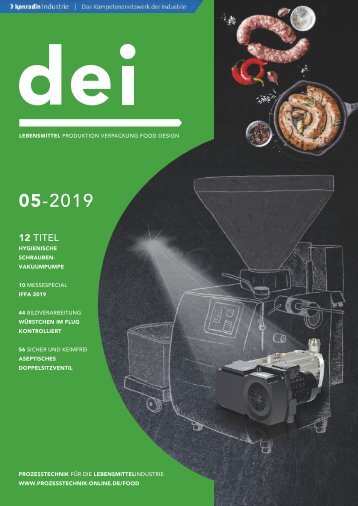
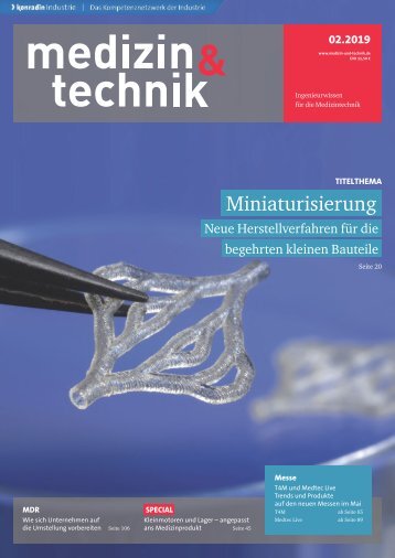
» PCB & ASSEMBLY 3D scan of the printed leadframe The stencil and squeegee unit in the SERIO printer are in a fixed position relative to one another. This means that the best possible position for the stencil is precisely set at the start and will remain accurate over the complete production run, and again and again. A highprecision, camera-based set-up for the stencils is of great importance here. In addition, screws on the bars of the stencil support and the squeegee holder can also be altered if required. This way, the position of the squeegee can be precisely adjusted transverse to the printing direction – absolutely matching the topography of the stencil. The optimum orientation ensuring the machine parts and the stencil are in exact relation to one another also has the advantage of making the peeling process on the stencil top of the Advanced Print Head as gentle as possible, significantly reducing wear. The squeegee blade peeling process takes place on two different surfaces: one on the top of the stencil and one on the deeper surface within the cavity. It must be ensured that the squeegee is printing with continuous force across the entire blade stroke. The pneumatically controlled EKRA squeegee head with closed-loop control guarantees this by permanently comparing the target and current values of the pressure force. In the present version of the Advanced Print Head, an even narrower tolerance window has been achieved. If the stencil steps and cavities are asymmetrically distributed over the print area, the oscillating movement of the squeegee can be limited through adjustment screws to improve the peel-off behavior. Source: Christian Koenen dimensional topography of the measured object. By using position, gray value, and height filter, the pixels which represent the height values of the printed paste volume can be determined. This is then made up of the sum of the pixel heights multiplied by the pixel area. It follows, then, that the smaller the pixels, the more precise the volume calculation. Pixel heights are determined using relative measurements of the area around them. For usual system applications such as those on printed circuit boards and ceramic substrates, this method is the correct and reasonable approach. When we print into a cavity, however, how does this work? In such an application, determining the zero line needed for the measurement of the relative height becomes difficult. Additionally, the user is confronted with a lot of measurement noise due to the influences of the surrounding area such as the high rim of the cavity. So how can we overcome these measurement challenges? If there is not enough space in the cavity, the inspection algorithm calculates the reference height outside the cavity and measures the height in a negative direction. The result is thus inverted. If the space is sufficient to determine the reference height, however, then the walls of the cavity will still distort the measurement. Due to the higher outer surfaces, an interfering signal can occur, since the reference height is probably outside the regular measuring range. Moreover, there is a disturbing shadow effect. This is because the projected moiré pattern (the measuring light) is partially blocked by the edges of the cavity. The Meister S inspection system has been designed to overcome this challenging measurement issue and therefore delivers excellent results. Special filters, known as ‘jig noise filters’, eliminate the measurement noise caused by the edges of the cavity. These filters are also used for the measurement of small 3D measurements and pixel heights All 3D measurements (of the paste application) were based on heights information acquired using the inspection system Meister S. The height information from each single camera pixel combines to provide a three- Shadowing due to the cavity wall Source: Koh Young 30 EPP Europe » 11 | 2021
substrates in a workpiece carrier. The inspection system uses various pieces of information to determine the reference height. If there is not enough space in the cavity, the heights of local and global alignment marks are used, or freely definable reference points can be set. The Meister S uses four 3D projector units to generate the moiré information. By superimposing the information from all four projection modules, shadows can be fully eliminated because the cavity is completely illuminated from all four directions. Last but not least, the small pixel size of 5 μm guarantees a very precise 3D reconstruction of the printed paste, thus ensuring a high repeatability of measurements with a Cgk