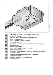
Create successful ePaper yourself
Turn your PDF publications into a flip-book with our unique Google optimized e-Paper software.
ENGLISH<br />
3.8.5 Connecting safety equipment<br />
▶ See Figure 6.5<br />
A dynamic 2-wire photocell can be connected as safety<br />
equipment in the closing direction.<br />
Terminal assignment:<br />
4<br />
Terminal 20<br />
Terminal 18<br />
Terminal 71<br />
Terminal 5<br />
0 V (power supply)<br />
Test signal<br />
Safety equipment signal<br />
+24 V (power supply)<br />
Putting into Service<br />
Warning<br />
Danger of injury during gate travel<br />
If people or objects are in the area<br />
around the gate while the gate is in<br />
motion, this can lead to injuries or<br />
damage.<br />
▶ Make sure that children are not<br />
playing near the gate system.<br />
▶ Make sure that no persons or<br />
objects are in the gate's travel<br />
range.<br />
▶ If the gate system only has one<br />
safety feature, only operate the<br />
sliding gate operator if you are<br />
within sight of the gate's travel<br />
range.<br />
▶ Monitor the gate travel until the gate<br />
has reached the end-of-travel<br />
position.<br />
▶ Only drive or pass through remote<br />
control gate systems when the gate<br />
is at a standstill!<br />
WARNING<br />
Danger of crushing and shearing<br />
Fingers or limbs may be crushed and severed if caught in<br />
the toothed track or between the gate and closing edge<br />
while the gate is in motion.<br />
▶ Whenever the gate is moving, never touch the toothed<br />
track, toothed wheel, and the main or secondary<br />
closing edges.<br />
4.1 Preparation<br />
▶ Before initial start-up, check that all the connecting leads<br />
are correctly installed at the connecting terminals.<br />
▶ Make sure that all DIL switches are set to the factory<br />
setting (OFF) (see Figure 7), the gate is half open and the<br />
operator engaged.<br />
Change the following DIL switches:<br />
▶ DIL switch 1: Installation direction (see Figure 7.1)<br />
– To ON, if the gate closes towards the right.<br />
– To OFF, if the gate closes towards the left.<br />
▶ DIL switch 3: Safety equipment (see Figure 9.3)<br />
– To ON if safety equipment is connected ( see<br />
sections 3.8.5 and 5.3). Is, however, not active during<br />
set-up mode.<br />
4.2 Teaching in the gate's end-of-travel positions<br />
4.2.1 Recording the CLOSE end-of-travel position<br />
▶ See Figure 8.1a<br />
The limit switch (reed contact) must be connected before<br />
teaching in the end-of-travel positions. The limit switch wires<br />
must be connected at the REED terminal.<br />
The option relay has the same function as the red LED during<br />
set-up. The limit switch position can be viewed from afar with<br />
a lamp connected to it (see Figure 6.4).<br />
Teaching in the CLOSE end-of-travel position:<br />
1. Open the gate halfway.<br />
2. Set DIL switch 2 (set-up mode) to ON.<br />
The green LED slowly flashes, the red LED remains lit.<br />
3. Press circuit board button T and keep it pressed.<br />
The gate now travels in CLOSE direction at slow speed.<br />
The gate stops once the limit switch has been reached.<br />
4. Immediately release circuit board button T.<br />
The red LED goes out.<br />
The gate is now in the CLOSE end-of-travel position.<br />
Note:<br />
If the gate travels in the opening direction, DIL switch 1 is in<br />
the wrong position and must be reset. Then repeat steps 1 to<br />
4.<br />
If the position of the gate does not correspond to the desired<br />
CLOSE position, a readjustment must be made.<br />
Readjusting the CLOSE end-of-travel position:<br />
1. Adjust the position of the magnet by moving the magnet<br />
slide.<br />
2. Press circuit board button T until the gate reaches the<br />
readjusted end-of-travel position and the red LED goes<br />
out.<br />
3. Repeat steps 1 + 2 until the desired end-of-travel<br />
position has been reached.<br />
4.2.2 Recording the OPEN end-of travel position<br />
▶ See Figure 8.1b<br />
Teaching in the OPEN end-of-travel position:<br />
1. Press circuit board button T and keep it pressed.<br />
The gate now travels in OPEN direction at slow speed.<br />
2. Release circuit board button T once the desired OPEN<br />
end-of-travel position is reached.<br />
3. Press circuit board button P to confirm this position.<br />
The green LED flashes rapidly for 2 seconds to indicate<br />
that the OPEN end-of-travel position has been recorded<br />
and then goes out.<br />
4.2.3 Recording the partial opening end-of-travel<br />
position<br />
▶ See Figure 8.1c<br />
Teaching in the partial opening end-of-travel position:<br />
1. Press circuit board button T and keep it pressed to move<br />
the gate back towards the CLOSE position.<br />
The green LED will flash slowly.<br />
2. Release circuit board button T once the desired partial<br />
opening end-of-travel position is reached.<br />
3. Press circuit board button P to confirm this position.<br />
The green LED flashes rapidly for 2 seconds to indicate<br />
that the partial opening end-of-travel position has been<br />
recorded and then goes out.<br />
TR10L019-A RE / 05.2010 11