GT650 GT660 GT670 - Repair - Black and Decker
GT650 GT660 GT670 - Repair - Black and Decker
GT650 GT660 GT670 - Repair - Black and Decker

Create successful ePaper yourself
Turn your PDF publications into a flip-book with our unique Google optimized e-Paper software.
Fitting your own extension cable<br />
◆ When making your own extension cable,<br />
fit a 13 Amp plug to one end of the cable<br />
(see “Mains plug replacement”) <strong>and</strong> a female<br />
connector to the other end.<br />
For wiring instructions, see those supplied with<br />
the female connector.<br />
◆ A male connector (see below) is already<br />
attached to the power supply cable on your<br />
tool. It is non-rewireable <strong>and</strong> should not be<br />
removed. If the connector is damaged <strong>and</strong><br />
needs replacement, take the tool to a<br />
<strong>Black</strong> & <strong>Decker</strong> service centre.<br />
female connector male connector<br />
Never wire an extension cable with<br />
anything other than the female connector<br />
supplied <strong>and</strong> a 13 Amp BS1363A<br />
approved plug with the recommended<br />
fuse. Never wire a male connector to the<br />
extension cable. Never wire an extension<br />
cable with a plug of any kind at each end<br />
of the cable. This is extremely dangerous<br />
<strong>and</strong> results in the pins being live, which<br />
may cause a fatal electric shock.<br />
CARTON CONTENTS<br />
The carton contains:<br />
1 Hedgetrimmer<br />
1 Blade sheath<br />
1 Guard<br />
6 Screws<br />
1 Instruction manual<br />
◆ Carefully unpack all parts.<br />
◆ Please note that additional items may be found<br />
in the carton, depending on the letter suffix<br />
following the catalogue number of your tool.<br />
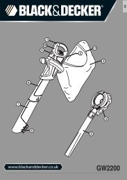
OVERVIEW (fig. A)<br />
1. Front h<strong>and</strong>le switch<br />
2. Trigger switch<br />
3. Lock-off button<br />
4. Front h<strong>and</strong>le<br />
5. Locking knob for front h<strong>and</strong>le<br />
6. Guard<br />
7. Locking h<strong>and</strong>le for cassette<br />
8. H<strong>and</strong>le cover<br />
9. Blade<br />
10. Blade cassette<br />
11. Blade sheath<br />
ASSEMBLY<br />
ENGLISH<br />
Before assembly, make sure that the tool<br />
is switched off <strong>and</strong> unplugged.<br />
Fit the blade sheath over the blades.<br />
You will need a number 2 Posidrive screwdriver for<br />
assembly.<br />
Fitting the front h<strong>and</strong>le (fig. B1 - B3)<br />
◆ Loosen the locking knob (5) a few turns (fig. B1).<br />
◆ Slide the h<strong>and</strong>le (4) into position (A).<br />
◆ Press the h<strong>and</strong>le into the location on the<br />
bottom of the tool (B).<br />
◆ Fit the h<strong>and</strong>le cover (8) in place <strong>and</strong> secure it<br />
with the 4 screws (12) supplied (fig. B2).<br />
◆ Set the front h<strong>and</strong>le (4) to a comfortable<br />
operating position (fig. B3).<br />
◆ Secure the h<strong>and</strong>le by tightening the locking<br />
knob (5).<br />
Fitting the guard (fig. C)<br />
◆ Place the guard (6) onto the tool as shown.<br />
◆ Secure the guard using the two screws (13)<br />
supplied.<br />
Never use the tool without the guard.<br />
Fitting the blade cassette (fig. D1 - D3)<br />
◆ Set the locking h<strong>and</strong>le (7) to the unlocked<br />
position (fig. D1).<br />
◆ Place the blade cassette (10) onto the motor<br />
unit, aligning the 3 pins on the motor unit with<br />
the holes in the cassette.<br />
◆ Set the locking h<strong>and</strong>le to the locked position<br />
(fig. D2) to secure the cassette (fig. D3).<br />
11