

Catálago de Acerogrill.
Catálago de Acerogrill.
Catálago de Acerogrill.

Create successful ePaper yourself
Turn your PDF publications into a flip-book with our unique Google optimized e-Paper software.
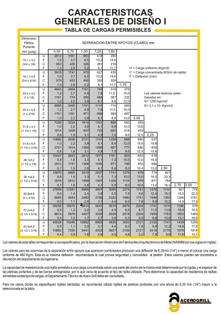
CARACTERISTICAS<br />
GENERALES DE DISEÑO I<br />
TABLA DE CARGAS PERMISIBLES<br />
Dimension<br />
Pletina<br />
Portante<br />
SEPARACION ENTRE APOYOS (CLARO) mts<br />
mm (pulg) 0,50 0,75 1,00 1,25 1,50<br />
U 2612 1161 653 418 290<br />
19,1 x 3,2 F 1,6 3,7 6,5 10,2 14,6<br />
(3/4 x 1/8) C 653 435 326 261 218<br />
F 1,3 2,9 5,2 8,1 11,7 U = Carga uniforme (Kg/m2)<br />
U 3918 1741 979 627 435 C = Carga concentrada (KG/m <strong>de</strong> rejilla)<br />
19,1 x 4,8 F 1,6 3,7 6,5 10,2 14,6 F = Deflexión (mm)<br />
(3/4 x 3/16) C 979 653 490 392 326<br />
F 1,3 2,9 5,2 8,1 11,7 1.75<br />
U 4643 2064 1161 743 516 379<br />
25,4 x 3,2 F 1,2 2,7 4,9 7,6 11,0 15,0 Los valores teóricos estan<br />
(1 x 1/8) C 1161 774 580 464 387 332 basados en:<br />
F 1,0 2,2 3,9 6,1 8,8 12,0 fx= 1250 kg/cm2<br />
U 6965 3095 1741 1114 774 569 E= 2,1 x 10 Kg/cm2<br />
25,4 x 4,8 F 1,2 2,7 4,9 7,6 11,0 15,0<br />
(1 x 3/16) C 1741 1161 871 696 580 497<br />
F 1,0 2,2 3,9 6,1 8,8 12,0 2.00<br />
U 7255 3224 1814 1161 806 592 453<br />
31,8 x 3,2 F 1,0 2,2 3,9 6,1 8,8 12,0 15,6<br />
(1 1/4 x 1/8) C 1814 1209 907 725 605 518 453<br />
F 0,8 1,8 3,1 4,9 7,0 9,6 12,5 2.25<br />
U 10882 4836 2721 1741 1209 888 680 537<br />
31,8 x 4,8 F 1,0 2,2 3,9 6,1 8,8 12,0 15,6 19,8<br />
(1 1/4 x 3/16) C 2721 1814 1360 1088 907 777 680 605<br />
F 0,8 1,8 3,1 4,9 7,0 9,6 12,5 15,8<br />
U 10447 4643 2612 1671 1161 853 653 516<br />
38,1x3,2 F 0,8 1,8 3,3 5,1 7,3 10,0 13,0 16,5<br />
(1 1/2 x 1/8) C 2612 1741 1306 1045 871 746 653 580<br />
F 0,7 1,5 2,6 4,1 5,9 8,0 10,4 13,2 2.50<br />
U 15670 6965 3918 2507 1741 1279 979 774 627<br />
38,1x4,8 F 0,8 1,8 3,3 5,1 7,3 10,0 13,0 16,5 20,3<br />
(1 1/2 x 3/16) C 3918 2612 1959 1567 1306 1119 979 871 784<br />
F 0,7 1,5 2,6 4,1 5,9 8,0 10,4 13,2 16,3 2.75 3.00<br />
U 27858 12381 6965 4457 3095 2274 1741 1376 1114 921 774<br />
50,8x4,8 F 0,6 1,4 2,4 3,8 5,5 7,5 9,8 12,4 15,3 18,5 22,0<br />
(2 x 3/16) C 6965 4643 3482 2786 2322 1990 1741 1548 1393 1266 1161<br />
F<br />
U<br />
0,5<br />
35258<br />
1,1<br />
15670<br />
2,0<br />
2<br />
8814<br />
3,1<br />
5641<br />
4,4<br />
3918<br />
6,0<br />
2878<br />
7,8<br />
2204<br />
9,9<br />
1741<br />
12,2<br />
1410<br />
14,8<br />
1166<br />
17,6<br />
979<br />
57,2x4,8 F 0,5 1,2 2,2 3,4 4,9 6,6 8,7 11,0 13,6 16,4 19,5<br />
(2 1/4 x 3/16) C 8814 5876 4407 3526 2938 2518 2204 1959 1763 1603 1469<br />
F 0,4 1,0 1,7 2,7 3,9 5,3 6,9 8,8 10,8 13,1 15,6<br />
U 43528 19346 10882 6965 4836 3553 2721 2150 1741 1439 1209<br />
63,5x4,8 F 0,5 1,1 2,0 3,1 4,4 6,0 7,8 9,9 12,2 14,8 17,6<br />
(2 1/2 x 3/16) C 10882 7255 5441 4353 3627 3109 2721 2418 2176 1979 1814<br />
F 0,4 0,9 1,6 2,4 3,5 4,8 3,2 7,9 9,8 11,8 14,1<br />
Los valores <strong>de</strong> esta tabla correspon<strong>de</strong>n a los especificados, por la Asociación Americana <strong>de</strong> Fabricantes Arquitectónicos <strong>de</strong> Metal (NAAMM por sus siglas en inglés)<br />
Los valores para las columnas <strong>de</strong> la separación entre apoyos que aparecen sombreados producen una <strong>de</strong>flexión <strong>de</strong> 6,35mm (1/4”) o menor al colocar una carga<br />
uniforme <strong>de</strong> 480 Kg/m. Esta es la máxima <strong>de</strong>flexión recomendada la cual provee seguridad y comodidad al peatón. Estos valores pue<strong>de</strong>n ser excedidos a<br />
discreción <strong>de</strong>l <strong>de</strong>partamento <strong>de</strong> ingeniería.<br />
La capacidad <strong>de</strong> resistencia <strong>de</strong> una rejilla sometida a una carga concentrada sobre una parte <strong>de</strong>l ancho <strong>de</strong> la misma está <strong>de</strong>terminada por la rigi<strong>de</strong>z y el espesor <strong>de</strong><br />
las pletinas portantes y <strong>de</strong> las barras entregiradas, por lo que varía <strong>de</strong> acuerdo al tipo <strong>de</strong> rejilla utilizado. Para <strong>de</strong>terminar la capacidad <strong>de</strong> resistencia <strong>de</strong> rejillas<br />
sometidas a este tipo <strong>de</strong> cargas, el Departamento Técnico <strong>de</strong> Acero Grill <strong>de</strong>be ser consultado.<br />
Para los casos don<strong>de</strong> se especifiquen rejillas <strong>de</strong>ntadas, se recomienda utilizar rejillas <strong>de</strong> pletinas portantes con una altura <strong>de</strong> 6,35 mm (1/4”) mayor a la<br />
seleccionada en la tabla.<br />
ACEROGRILL