VSE/200.01 istr. nuove - Tribpt
VSE/200.01 istr. nuove - Tribpt
VSE/200.01 istr. nuove - Tribpt

You also want an ePaper? Increase the reach of your titles
YUMPU automatically turns print PDFs into web optimized ePapers that Google loves.
GB INSTALLATION<br />
INSTRUCTIONS<br />
<strong>VSE</strong>/<strong>200.01</strong> SELECTOR<br />
FOR INTERCOM UNITS<br />
This selector allows the installation of<br />
groups of intercom receivers in<br />
installation with standard receivers<br />
(system 200).<br />
The selector is equipped with a continuous<br />
tone generator for internal<br />
calls between intercom units.<br />
The appliance permits internal conversation<br />
between intercom receivers,<br />
even during communication<br />
between the entry panel and another<br />
occupant.<br />
During internal or external communication,<br />
a red LED illuminates on the<br />
receivers (if are equipped) to indicate<br />
that the line is engaged. During<br />
internal conversations between intercom<br />
receivers, the selector guarantees<br />
complete audio privacy and<br />
hence, conversation confidentiality,<br />
with respect to the entry panel.<br />
The selector permits, in video entry<br />
systems, the installation of the intercom<br />
handset, provided an EKC/200<br />
capacitor is also installed in the mod.<br />
C/200.<br />
In audio entry system the EKC/200<br />
capacitor must be used in installation<br />
with secrecy of speech and<br />
C/200 receivers.<br />
With this selector you can create<br />
systems whereby receivers are activated<br />
by the same call or an individual<br />
call.<br />
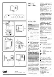
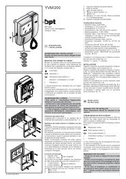
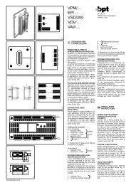
The selector for intercom receivers<br />
may be installed in the wall support,<br />
figure 2, in the XC/200 receiver, figure<br />
3, in a standard embedding box<br />
(90x90x40 mm) or on a DIN rail (EN<br />
50022), figure 4.<br />
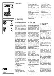
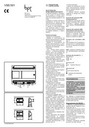
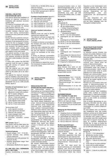
Function of each terminal, figure 1<br />
Terminal block IN<br />
5 − 14.5÷17.5V supply voltage to<br />
6 + selector (video entry system)<br />
5 − 11V supply voltage to<br />
21 + selector (audio entry system)<br />
7 call no. 1 from entry panel<br />
8 audio signal from entry panel<br />
9 audio signal to entry panel<br />
7A call no. 2 from entry panel<br />
7B call no. 3 from entry panel<br />
Terminal block OUT<br />
8 audio signal to receiver<br />
9 audio signal from receiver<br />
13 intercom call common<br />
17 output engaged (red LED)<br />
18 stair light control input<br />
19 automatic activation control<br />
input<br />
SW1 jumper, figure 1<br />
This jumper must be fitted when the<br />
selector are used in audio entry<br />
systems without secrecy of speech.<br />
Technical features<br />
• Supply voltage: 14.5 ÷ 17.5V DC.<br />
• Current demand: max. 200mA<br />
(20mA quiescent).<br />
• Continuous tone call generator for<br />
intercom facility.<br />
• Working temperature range: from<br />
0 °C to +35 °C.<br />
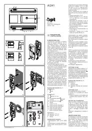
• Dimensions: 60x44x16 mm, figure 5.<br />
P/3 AND XP/3 CALL EXPANSION<br />
WITH 3 BUTTONS<br />
Enables transforming a standard<br />
2<br />
C/200 (P/3) or XC/200 (XP/3) into an<br />
intercom handset.<br />
A maximum of 4 P/3 can be installed<br />
in the C/200 handset and 2 XP/3 in<br />
the XC/200 handset.<br />
Function of each terminal, figure 6-7<br />
12 call output from entry panel<br />
7 call input from entry panel<br />
13 intercom call common<br />
14 call to handset no. 1 (4-7-10)<br />
15 call to handset no. 2 (5-8-11)<br />
16 call to handset no. 3 (6-9-12)<br />
Intercom handset instructions<br />
for use<br />
Different tones are used to identify<br />
internal from external calls.<br />
The intercom call tone is single note<br />
whilst that from the entry panel is<br />
dual note.<br />
To initiate an internal conversation lift<br />
the handset and press the desired<br />
intercom button.<br />
When the call is attended the audio<br />
line to the entry panel is disconnected<br />
and the intercom conversation<br />
cannot be overheard at the entry<br />
panel.<br />
If during an intercom conversation<br />
there is a call from the entry panel a<br />
softer note is heard in the handset<br />
loudspeaker.<br />
In this instance to attend the call it is<br />
first necessary to replace both handset<br />
on the cradle.<br />
D INSTALLATIONS-<br />
ANLEITUNG<br />
WÄHLSCHALTER FÜR<br />
INTERCOM-ANLAGEN <strong>VSE</strong>/<strong>200.01</strong><br />
Der Wählschalter erlaubt die<br />
Zuschaltung von Innensprechstellen<br />
mit Intercom-Funktion in Anlagen mit<br />
standarder Innensprechstellen<br />
(System 200). Er ist mit einem Dauertonerzeuger<br />
für Anrufe zwischen<br />
Innensprechstellen ausgestattet.<br />
Das Gerät erlaubt Gespräche swischen<br />
Intercom-Innensprechstellen<br />
auch während eines Gespräches<br />
zwischen einer Außenstation und<br />
einer anderen Innensprechstellen.<br />
Während eines internen oder externen<br />
Gespräches zeigt eine rote LED<br />
den Sprechgarnituren falls da an,<br />
daß die Leitung besetzt ist.<br />
Während eines Gespräches zwischen<br />
Intercom-Sprechstellen,<br />
gewährleistet der Wählschalter die<br />
vollständige Trennung des Audiosignals<br />
(und damit den Mithörschutz)<br />
in Hinsicht auf die Außenstation.<br />
Das Gerät erlaubt, in Video-<br />
Türsprechanlagen, den Einsatz der<br />
Intercom-Sprechgarnitur, sofern der<br />
Kondensator EKC/200, in der mod.<br />
C/200, vorhanden ist.<br />
In Haussprechanlagen muß der<br />
Kondensator EKC/200 in Anlagen<br />
mit Mithörsperre und Sprechgarnitur<br />
C/200 verwendet werden.<br />
Mit diesem Wählschalter können<br />
Anlagen mit Innensprechstellen<br />
installiert werden, die von demselben<br />
Anruf oder von einem spezifischen<br />
Anruf eingeschaltet werden.<br />
Der Wählschalter für Intercom-<br />
Innensprechstellen kann in dem<br />
Wandmontagehalter (Abb. 2), in der<br />
Sprechgarnitur C/200 (Abb. 3), in<br />
einer normalen Abzweigdose<br />
(90x90x40 mm) oder auf DIN<br />
Schiene (EN 50022) (Abb. 5) installiert<br />
werden.<br />
Belegung der Klemmleisten<br />
(Abb. 1)<br />
Klemmleiste IN<br />
5 − 14,5÷17,5V Stromversorgung<br />
6 + des Wählschalters<br />
(Video-Türsprechanlagen)<br />
5 − 11V Stromversorgung des<br />
21 + Wählschalters<br />
(Haussprechanlagen)<br />
7 Ruf Nr. 1 von der Außenstation<br />
8 Audiosignal von der Außenstation<br />
9 Audiosignal zur Außenstation<br />
7A Ruf Nr. 2 von der Außenstation<br />
7B Ruf Nr. 3 von der Außenstation<br />
Klemmleiste OUT<br />
8 Audiosignal zum Innensprechstelle<br />
9 Audiosignal vom Innensprechstelle<br />
13 Sammelleiter für Intercom-Anruf<br />
17 Ausgang für Besetztanzeige<br />
(rote LED)<br />
18 Eingang für Treppenlicht<br />
19 Eingang für Selbsteinschaltung<br />
Brücke SW1 (Abb. 1)<br />
Diese Brücke muß, wenn an der<br />
Wähler in Sprechanlagen ohne<br />
Mithörsperre benutzt (System 200),<br />
eingeschaltet werden.<br />
Technische Daten<br />
• Stromversorgung: 14,5 ÷ 17,5V DC.<br />
• Stromaufnahme: max. 200mA<br />
(20mA Ruhestrom).<br />
• Dauertonerzeuger für Intercom-<br />
Anrufe.<br />
• Betriebstemperatur: 0 °C bis +35<br />
°C.<br />
• Abmessungen: 60x44x16 mm (Abb.<br />
5).<br />
RUFERWEITERUNG<br />
MIT 3 TASTEN P/3 UND XP/3<br />
Verwandelt eine einfache Sprechgarnitur<br />
C/200 (P/3) oder XC/200<br />
(XP/3) in ein Intercom-Gerät.<br />
An der Sprechgarnitur C/200 lassen<br />
sich maximal 4 P/3 und XC/200 swei<br />
XP/3 installieren.<br />
Belegung der Klemmleisten<br />
(Abb. 6-7)<br />
12 Ausgang Anruf zur Außenstation<br />
7 Eingang Anruf zur Außenstation<br />
13 Sammelleiter für Intercom-Anruf<br />
14 Ruf zur Hörer Nr. 1 (4-7-10)<br />
15 Ruf zur Hörer Nr. 2 (5-8-11)<br />
16 Ruf zur Hörer Nr. 3 (6-9-12)<br />
Bedienungsanleitungen<br />
für Intercom-Sprechgarnitur<br />
Unterschiedlicher Rufton zur<br />
Rufunterscheidung von internen und<br />
externen Anrufen.<br />
Der interne Rufton ist ein<br />
Enfachrufton gegenüber über dem<br />
Zweiklangton für den externen Ruf.<br />
Für eine interne Sprechverbindung<br />
ist der Hörer abzunehmen und die<br />
entsprechende Intercomtaste zu<br />
drücken.<br />
Für den Fall, dass zuvor die<br />
Sprechverbindung zur Außenstation<br />
bestand, wird durch den internen<br />
Ruf die Verbindung zur Außenstation<br />
unterbrochen, wobei das interne<br />
Gespräch an der Außenstation nicht<br />
mitgehört werden kann. Bei Anruf<br />
von der Außenstation während eines<br />
internen Gespräches ist der<br />
Zweiklang-Rufton über den<br />
Lautsprecher der Sprechgarnitur<br />
hörbar.<br />
Um das Gespräch mit der<br />
Außenstation aufzunehmen, muss<br />
erst der Hörer aufgelegt, bzw. die<br />
Hörergabel betätigt werden.<br />
F<br />
INSTRUCTIONS<br />
POUR L’INSTALLATION<br />
SELECTEUR POUR POSTES<br />
A INTERCOMMUNICATION<br />
<strong>VSE</strong>/<strong>200.01</strong><br />
Le sélecteur permet d’insérer des<br />
groupes de postes intérieurs à intercommunication<br />
dans des installations<br />
avec postes intérieurs standard<br />
(système 200).<br />
Il est équipé d’un générateur à note<br />
continue pour l’appel entre les<br />
postes à intercommunication.<br />
L’appareil permet d’effectuer des<br />
conversations entre des postes à<br />
intercommunication même durant<br />
une communication entre le poste<br />
extérieur et un autre locataire.<br />
Pendant une communication interne<br />
ou externe (avec le poste extérieur),<br />
l’éclairage d’une LED rouge (si présent)<br />
sur les postes signale que la<br />
ligne est occupée.<br />
Pendant une conversation entre des<br />
postes à intercommunication, le<br />
sélecteur garantit la parfaite séparation<br />
audio (et donc la discrétion) par<br />
rapport au poste extérieur.<br />
L’appareil permet, dans installation<br />
portier vidéo, d’utiliser le combiné<br />
téléphonique à intercommunication,<br />
moyennant l’introduction préalable,<br />
dans le mod. C/200, du condensateur<br />
EKC/200.<br />
Avec le portier électronique le condensateur<br />
EKC/200 doit être utilisé<br />
dans installations avec secret de<br />
conversation et combiné téléphonique<br />
C/200.<br />
On peut réaliser, avec ce sélecteur,<br />
des installations avec des postes<br />
intérieurs activés par le même appel<br />
ou bien par un appel individuel.<br />
Le sélecteur pour postes à intercommunication<br />
peut être installé aussi<br />
bien dans le support mural (fig. 2),<br />
dans le combiné téléphonique<br />
XC/200 (fig. 3), dans un boîtier de<br />
dérivation normal (90x90x40 mm) ou<br />
sur rail DIN (EN 50022) (fig. 4).<br />
Fonction des bornes (fig. 1)<br />
Bornier IN<br />
5 − 14,5 ÷ 17,5V alimentation<br />
6 + sélecteur (portier vidéo)<br />
5 − 11V alimentation sélecteur<br />
21 + (portier électronique)<br />
7 appel n. 1 depuis le poste extérieur<br />
8 audio depuis le poste extérieur<br />
9 audio vers le poste extérieur<br />
7A appel n. 2 depuis le poste extérieur<br />
7B appel n. 3 depuis le poste extérieur