scheda tecnica accessorio VRCV - VRCH
scheda tecnica accessorio VRCV - VRCH
scheda tecnica accessorio VRCV - VRCH

You also want an ePaper? Increase the reach of your titles
YUMPU automatically turns print PDFs into web optimized ePapers that Google loves.
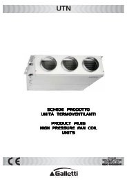
<strong>VRCV</strong> - <strong>VRCH</strong><br />
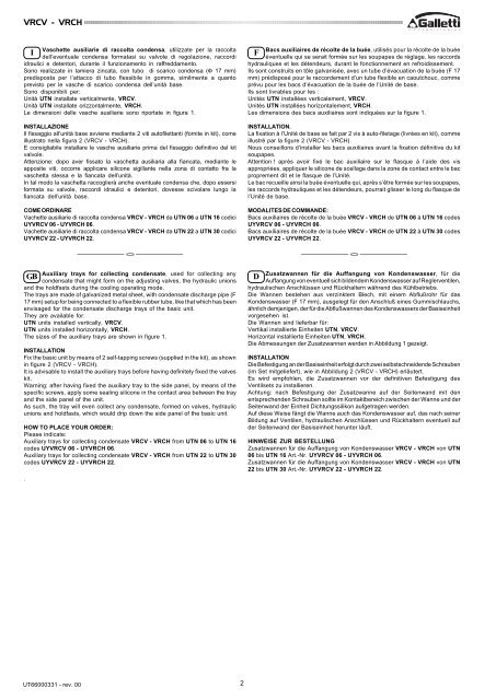
Vaschette ausiliarie di raccolta condensa, utilizzate per la raccolta<br />
I<br />
dell’eventuale condensa formatasi su valvole di regolazione, raccordi<br />
idraulici e detentori, durante il funzionamento in raffreddamento.<br />
Sono realizzate in lamiera zincata, con tubo di scarico condensa (Φ 17 mm)<br />
predisposta per l’attacco di tubo flessibile in gomma, similmente a quanto<br />
previsto per le vasche di scarico condensa dell’unità base.<br />
Sono disponibili per:<br />
Unità UTN installate verticalmente, <strong>VRCV</strong>.<br />
Unità UTN installate orizzontalmente, <strong>VRCH</strong>.<br />
Le dimensioni delle vasche ausiliarie sono riportate in figura 1.<br />
INSTALLAZIONE<br />
Il fissaggio all’unità base avviene mediante 2 viti autofilettanti (fornite in kit), come<br />
illustrato nella figura 2 (<strong>VRCV</strong> - <strong>VRCH</strong>).<br />
E consigliabile installare le vasche ausiliarie prima del fissaggio definitivo del kit<br />
valvole.<br />
Attenzione: dopo aver fissato la vaschetta ausiliaria alla fiancata, mediante le<br />
apposite viti, occorre applicare silicone sigillante nella zona di contatto fra la<br />
vaschetta stessa e la fiancata dell’unità.<br />
In tal modo la vaschetta raccoglierà anche eventuale condensa che, dopo essersi<br />
formata su valvole, raccordi idraulici e detentori, dovesse scivolare lungo la<br />
fiancata dell’unità base.<br />
COME ORDINARE<br />
Vachette ausiliarie di raccolta condensa <strong>VRCV</strong> - <strong>VRCH</strong> da UTN 06 a UTN 16 codici<br />
UY<strong>VRCV</strong> 06 - UY<strong>VRCH</strong> 06.<br />
Vachette ausiliarie di raccolta condensa <strong>VRCV</strong> - <strong>VRCH</strong> da UTN 22 a UTN 30 codici<br />
UY<strong>VRCV</strong> 22 - UY<strong>VRCH</strong> 22.<br />
Bacs auxiliaires de récolte de la buée, utilisés pour la récolte de la buée<br />
F<br />
éventuelle qui se serait formée sur les soupapes de réglage, les raccords<br />
hydrauliques et les détendeurs, durant le fonctionnement en refroidissement.<br />
Ils sont construits en tôle galvanisée, avec un tube d’évacuation de la buée (F 17<br />
mm) prédisposé pour le raccordement d’un tube flexible en caoutchouc, comme<br />
prévu pour les bacs d’évacuation de la buée de l’Unité de base.<br />
Ils sont livrables pour les :<br />
Unités UTN installées verticalement, <strong>VRCV</strong>.<br />
Unités UTN installées horizontalement, <strong>VRCH</strong>.<br />
Les dimensions des bacs auxiliaires sont indiquées sur la figure 1.<br />
INSTALLATION.<br />
La fixation à l’Unité de base se fait par 2 vis à auto-filetage (livrées en kit), comme<br />
illustré par la figure 2 (<strong>VRCV</strong> - <strong>VRCH</strong>).<br />
Nous conseillons d’installer les bacs auxiliaires avant la fixation définitive du kit<br />
soupapes.<br />
Attention ! après avoir fixé le bac auxiliaire sur le flasque à l’aide des vis<br />
appropriées, appliquer le silicone de scellage dans la zone de contact entre le bac<br />
proprement dit et le flasque de l’Unité.<br />
Le bac recueille ainsi la buée éventuelle qui, après s’être formée sur les soupapes,<br />
les raccords hydrauliques et les détendeurs, pourrait glisser le long du flasque de<br />
l’Unité de base.<br />
MODALITES DE COMMANDE:<br />
Bacs auxiliaires de récolte de la buée <strong>VRCV</strong> - <strong>VRCH</strong> de UTN 06 à UTN 16 codes<br />
UY<strong>VRCV</strong> 06 - UY<strong>VRCH</strong> 06.<br />
Bacs auxiliaires de récolte de la buée <strong>VRCV</strong> - <strong>VRCH</strong> de UTN 22 à UTN 30 codes<br />
UY<strong>VRCV</strong> 22 - UY<strong>VRCH</strong> 22.<br />
Auxiliary trays for collecting condensate, used for collecting any<br />
GB<br />
condensate that might form on the adjusting valves, the hydraulic unions<br />
and the holdfasts during the cooling operating mode.<br />
The trays are made of galvanized metal sheet, with condensate discharge pipe (F<br />
17 mm) setup for being connected to a flexible rubber tube, like that which has been<br />
envisaged for the condensate discharge trays of the basic unit.<br />
They are available for:<br />
UTN units installed vertically, <strong>VRCV</strong>.<br />
UTN units installed horizontally, <strong>VRCH</strong>.<br />
The sizes of the auxiliary trays are shown in figure 1.<br />
INSTALLATION<br />
Fix the basic unit by means of 2 self-tapping screws (supplied in the kit), as shown<br />
in figure 2 (<strong>VRCV</strong> - <strong>VRCH</strong>).<br />
It is advisable to install the auxiliary trays before having definitely fixed the valves<br />
kit.<br />
Warning: after having fixed the auxiliary tray to the side panel, by means of the<br />
specific screws, apply some sealing silicone in the contact area between the tray<br />
and the side panel of the unit.<br />
As such, the tray will even collect any condensate, formed on valves, hydraulic<br />
unions and holdfasts, which would drip down the side panel of the basic unit.<br />
HOW TO PLACE YOUR ORDER:<br />
Please indicate:<br />
Auxiliary trays for collecting condensate <strong>VRCV</strong> - <strong>VRCH</strong> from UTN 06 to UTN 16<br />
codes UY<strong>VRCV</strong> 06 - UY<strong>VRCH</strong> 06.<br />
Auxiliary trays for collecting condensate <strong>VRCV</strong> - <strong>VRCH</strong> from UTN 22 to UTN 30<br />
codes UY<strong>VRCV</strong> 22 - UY<strong>VRCH</strong> 22.<br />
.<br />
Zusatzwannen für die Auffangung von Kondenswasser, für die<br />
D<br />
Auffangung von eventuell sich bildendem Kondenswasser auf Reglerventilen,<br />
hydraulischen Anschlüssen und Rückhaltern während des Kühlbetriebs.<br />
Die Wannen bestehen aus verzinktem Blech, mit einem Abflußrohr für das<br />
Kondenswasser (F 17 mm), ausgelegt für den Anschluß eines Gummischlauchs,<br />
ähnlich demjenigen, der für die Abflußwannen des Kondenswassers der Basiseinheit<br />
vorgesehen ist.<br />
Die Wannen sind lieferbar für:<br />
Vertikal installierte Einheiten UTN, <strong>VRCV</strong>.<br />
Horizontal installierte Einheiten UTN, <strong>VRCH</strong>.<br />
Die Abmessungen der Zusatzwannen werden in Abbildung 1 gezeigt.<br />
INSTALLATION<br />
Die Befestigung an der Basiseinheit erfolgt durch zwei selbstschneidende Schrauben<br />
(im Set mitgeliefert), wie in Abbildung 2 (<strong>VRCV</strong> - <strong>VRCH</strong>) erläutert.<br />
Es wird empfohlen, die Zusatzwannen vor der definitiven Befestigung des<br />
Ventilsets zu installieren.<br />
Achtung: nach Befestigung der Zusatzwanne auf der Seitenwand mit den<br />
entsprechenden Schrauben sollte im Kontaktbereich zwischen der Wanne und der<br />
Seitenwand der Einheit Dichtungssilikon aufgetragen werden.<br />
Auf diese Weise fängt die Wanne auch das Kondenswasser auf, das nach seiner<br />
Bildung auf Ventilen, hydraulischen Anschlüssen und Rückhaltern eventuell auf<br />
der Seitenwand der Basiseinheit herunter läuft.<br />
HINWEISE ZUR BESTELLUNG<br />
Zusatzwannen für die Auffangung von Kondenswasser <strong>VRCV</strong> - <strong>VRCH</strong> von UTN<br />
06 bis UTN 16 Art.-Nr. UY<strong>VRCV</strong> 06 - UY<strong>VRCH</strong> 06.<br />
Zusatzwannen für die Auffangung von Kondenswasser <strong>VRCV</strong> - <strong>VRCH</strong> von UTN<br />
22 bis UTN 30 Art.-Nr. UY<strong>VRCV</strong> 22 - UY<strong>VRCH</strong> 22.<br />
UT66000331 - rev. 00<br />
2