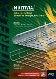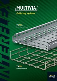
Cable tray systems Sistema de bandejas portacables - Interflex
Cable tray systems Sistema de bandejas portacables - Interflex
Cable tray systems Sistema de bandejas portacables - Interflex

You also want an ePaper? Increase the reach of your titles
YUMPU automatically turns print PDFs into web optimized ePapers that Google loves.
94<br />
General technical information<br />
Información técnica general<br />
Electrical continuity<br />
and ground connection<br />
Metallic cable <strong>tray</strong> <strong>systems</strong> should present an a<strong>de</strong>quate<br />
electrical continuity to ensure an equipotential connection<br />
and one or many ground connections if necessary<br />
(CEI 61537-01).<br />
According to continuity assay no. 11.1 of CEI 61537-01 values<br />
of impedance in MULTIVIA cable <strong>tray</strong>s and joining materials<br />
do not exceed 50 mΩ through the union of two cable <strong>tray</strong>s<br />
and 5 mΩ per metre of cable <strong>tray</strong> without the union.<br />
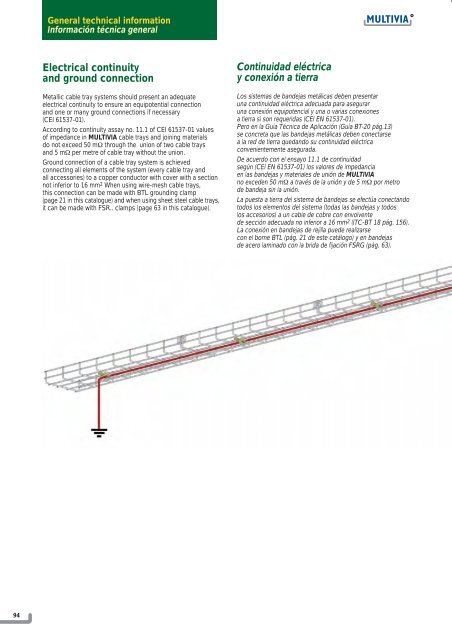
Ground connection of a cable <strong>tray</strong> system is achieved<br />
connecting all elements of the system (every cable <strong>tray</strong> and<br />
all accessories) to a copper conductor with cover with a section<br />
not inferior to 16 mm 2 When using wire-mesh cable <strong>tray</strong>s,<br />
this connection can be ma<strong>de</strong> with BTL grounding clamp<br />
(page 21 in this catalogue) and when using sheet steel cable <strong>tray</strong>s,<br />
it can be ma<strong>de</strong> with FSR.. clamps (page 63 in this catalogue).<br />
Continuidad eléctrica<br />
y conexión a tierra<br />
Los sistemas <strong>de</strong> ban<strong>de</strong>jas metálicas <strong>de</strong>ben presentar<br />
una continuidad eléctrica a<strong>de</strong>cuada para asegurar<br />
una conexión equipotencial y una o varias conexiones<br />
a tierra si son requeridas (CEI EN 61537-01).<br />
Pero en la Guía Técnica <strong>de</strong> Aplicación (Guía BT-20 pág.13)<br />
se concreta que las ban<strong>de</strong>jas metálicas <strong>de</strong>ben conectarse<br />
a la red <strong>de</strong> tierra quedando su continuidad eléctrica<br />
convenientemente asegurada.<br />
De acuerdo con el ensayo 11.1 <strong>de</strong> continuidad<br />
según (CEI EN 61537-01) los valores <strong>de</strong> impedancia<br />
en las ban<strong>de</strong>jas y materiales <strong>de</strong> unión <strong>de</strong> MULTIVIA<br />
no exce<strong>de</strong>n 50 mΩ a través <strong>de</strong> la unión y <strong>de</strong> 5 mΩ por metro<br />
<strong>de</strong> ban<strong>de</strong>ja sin la unión.<br />
La puesta a tierra <strong>de</strong>l sistema <strong>de</strong> ban<strong>de</strong>jas se efectúa conectando<br />
todos los elementos <strong>de</strong>l sistema (todas las ban<strong>de</strong>jas y todos<br />
los accesorios) a un cable <strong>de</strong> cobre con envolvente<br />
<strong>de</strong> sección a<strong>de</strong>cuada no inferior a 16 mm 2 (ITC-BT 18 pág. 156).<br />
La conexión en ban<strong>de</strong>jas <strong>de</strong> rejilla pue<strong>de</strong> realizarse<br />
con el borne BTL (pág. 21 <strong>de</strong> este catálogo) y en ban<strong>de</strong>jas<br />
<strong>de</strong> acero laminado con la brida <strong>de</strong> fijación FSRG (pág. 63).