1 - InstalacjeB2B
1 - InstalacjeB2B
1 - InstalacjeB2B
You also want an ePaper? Increase the reach of your titles
YUMPU automatically turns print PDFs into web optimized ePapers that Google loves.
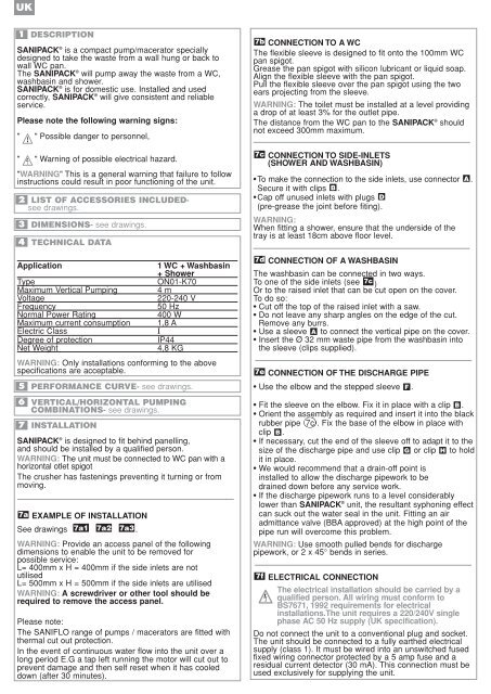
UK<br />
1<br />
DESCRIPTION<br />
SANIPACK ® is a compact pump/macerator specially<br />
designed to take the waste from a wall hung or back to<br />
wall WC pan.<br />
The SANIPACK ® will pump away the waste from a WC,<br />
washbasin and shower.<br />
SANIPACK ® is for domestic use. Installed and used<br />
correctly, SANIPACK ® will give consistent and reliable<br />
service.<br />
Please note the following warning signs:<br />
" " Possible danger to personnel,<br />
" " Warning of possible electrical hazard.<br />
"WARNING" This is a general warning that failure to follow<br />
instructions could result in poor functioning of the unit.<br />
2 LIST OF ACCESSORIES INCLUDEDsee<br />
drawings.<br />
3<br />
4<br />
DIMENSIONS- see drawings.<br />
TECHNICAL DATA<br />
Application 1 WC + Washbasin<br />
+ Shower<br />
Type ON01-K70<br />
Maximum Vertical Pumping 4 m<br />
Voltage 220-240 V<br />
Frequency 50 Hz<br />
Normal Power Rating 400 W<br />
Maximum current consumption 1,8 A<br />
Electric Class I<br />
Degree of protection IP44<br />
Net Weight 4,8 KG<br />
WARNING: Only installations conforming to the above<br />
specifications are acceptable.<br />
5<br />
6<br />
7<br />
PERFORMANCE CURVE- see drawings.<br />
VERTICAL/HORIZONTAL PUMPING<br />
COMBINATIONS- see drawings.<br />
INSTALLATION<br />
SANIPACK ® is designed to fit behind panelling,<br />
and should be installed by a qualified person.<br />
WARNING: The unit must be connected to WC pan with a<br />
horizontal otlet spigot<br />
The crusher has fastenings preventing it turning or from<br />
moving.<br />
7a EXAMPLE OF INSTALLATION<br />
See drawings 7a1 7a2 7a3 .<br />
WARNING: Provide an access panel of the following<br />
dimensions to enable the unit to be removed for<br />
possible service:<br />
L= 400mm x H = 400mm if the side inlets are not<br />
utilised<br />
L= 500mm x H = 500mm if the side inlets are utilised<br />
WARNING: A screwdriver or other tool should be<br />
required to remove the access panel.<br />
Please note:<br />
The SANIFLO range of pumps / macerators are fitted with<br />
thermal cut out protection.<br />
In the event of continuous water flow into the unit over a<br />
long period E.G a tap left running the motor will cut out to<br />
prevent damage and then self reset when it has cooled<br />
down (after 30 minutes).<br />
CONNECTION TO A WC<br />
The flexible sleeve is designed to fit onto the 100mm WC<br />
pan spigot.<br />
Grease the pan spigot with silicon lubricant or liquid soap.<br />
Align the flexible sleeve with the pan spigot.<br />
Pull the flexible sleeve over the pan spigot using the two<br />
ears projecting from the sleeve.<br />
WARNING: The toilet must be installed at a level providing<br />
a drop of at least 3% for the outlet pipe.<br />
The distance from the WC pan to the SANIPACK ® 7b<br />
should<br />
not exceed 300mm maximum.<br />
7c<br />
CONNECTION TO SIDE-INLETS<br />
(SHOWER AND WASHBASIN)<br />
•To make the connection to the side inlets, use connector A .<br />
Secure it with clips B .<br />
•Cap off unused inlets with plugs D<br />
(pre-grease the joint before fiting).<br />
WARNING:<br />
When fitting a shower, ensure that the underside of the<br />
tray is at least 18cm above floor level.<br />
7d CONNECTION OF A WASHBASIN<br />
The washbasin can be connected in two ways.<br />
To one of the side inlets (see 7c )<br />
Or to the raised inlet that can be cut open on the cover.<br />
To do so:<br />
• Cut off the top of the raised inlet with a saw.<br />
• Do not leave any sharp angles on the edge of the cut.<br />
Remove any burrs.<br />
• Use a sleeve A to connect the vertical pipe on the cover.<br />
• Insert the Ø 32 mm waste pipe from the washbasin into<br />
the sleeve (clips supplied).<br />
7e CONNECTION OF THE DISCHARGE PIPE<br />
• Use the elbow and the stepped sleeve F .<br />
• Fit the sleeve on the elbow. Fix it in place with a clip .<br />
• Orient the assembly as required and insert it into the black<br />
rubber pipe 7c . Fix the base of the elbow in place with<br />
clip .<br />
• If necessary, cut the end of the sleeve off to adapt it to the<br />
size of the discharge pipe and use clip or clip to hold<br />
it in place.<br />
• We would recommend that a drain-off point is<br />
installed to allow the discharge pipework to be<br />
drained down before any service work.<br />
• If the discharge pipework runs to a level considerably<br />
lower than SANIPACK ® B<br />
B<br />
G H<br />
unit, the resultant syphoning effect<br />
can suck out the water seal in the unit. Fitting an air<br />
admittance valve (BBA approved) at the high point of the<br />
pipe run will overcome this problem.<br />
WARNING: Use smooth pulled bends for discharge<br />
pipework, or 2 x 45° bends in series.<br />
7f ELECTRICAL CONNECTION<br />
The electrical installation should be carried by a<br />
qualified person. All wiring must conform to<br />
BS7671, 1992 requirements for electrical<br />
installations.The unit requires a 220/240V single<br />
phase AC 50 Hz supply (UK specification).<br />
Do not connect the unit to a conventional plug and socket.<br />
The unit should be connected to a fully earthed electrical<br />
supply (class 1). It must be wired into an unswitched fused<br />
fixed wiring connector protected by a 5 amp fuse and a<br />
residual current detector (30 mA). This connection must be<br />
used exclusively for supplying the unit.


