


Create successful ePaper yourself
Turn your PDF publications into a flip-book with our unique Google optimized e-Paper software.
• Installation on concrete slab compulsory and necessary for warranty to be valid. Thickness: 20 <strong>cm</strong> minimum. Ensure that slab is completely<br />
smooth and level.<br />
• Swimming pool should be oriented so that skimmer inlet(s) face(s) prevailing wind, in order to optimise surface particle filtration.<br />
Fit the planks together using the sacrifice part provided for this purpose.<br />
7<br />
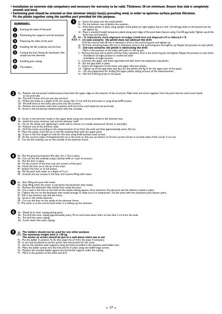
SUMMARY:<br />
- Erecting the sides of the pool<br />
- Positioning the supports and the brackets<br />
- Preparing the sides of the pool<br />
- Installing the felt underlay and the liner<br />
- Cutting the liner, fitting the backwash inlet<br />
nozzle and the skimmer<br />
- Installing pine coping<br />
- The ladders<br />
1a - Insert the posts into the metal plinths<br />
1b - Put the bottom row of planks into position.<br />
1c - Hold these planks in place using upright metal plates (at right angles). Secure with 12x160 japy bolts at the bottom but do<br />
not tighten up.<br />
1d - Place a standard length temporary plank along each edge of the pool basin. Secure using 12x120 japy bolts. Tighten up all the<br />
bolts (top and bottom).<br />
1e - To imperatively check alignment of wedges (chalk line) and diagonals (10 m ribbon); A = B<br />
1f - 1st case scenario: the plinth does not obstruct the drill:<br />
Drill the central hole (8 mm in diameter), drive in the anchoring pins and tighten up.<br />
1g - Drill the remaining holes (20 mm in diameter), drive in the anchoring pins and tighten up. Repeat the process on each plinth.<br />
1h - 2nd case scenario: the plinth is obstructing the drill:<br />
Mark in the position of the holes with paint or felt tip pen.<br />
1i - Remove the post and its plinth, drill the holes, reposition, drive in the anchoring pins and tighten. Repeat the process on each plinth.<br />
- Installation of angle junction in reinforced steel<br />
- Installation of angle junction<br />
1j - Unscrew the upper and lower japy bolts and take down the temporary top planks.<br />
1k - Put the japy bolts in place.<br />
1l - Check the alignment of the lower and upper skimmer planks.<br />
1m - Tighten up all the japy bolts (see fig. J for the plinths and fig. K for the upper part of the post).<br />
1n - Do the preparation for drilling the upper planks, taking account of the measurements.<br />
1o - Nail the finishing strips to the posts.<br />
2a - Position the horizontal reinforcements level with the upper edge on the exterior of the structure. Make level and screw together from the pool interior, until screw heads<br />
to not protrude.<br />
2b - Pre-drill 3 holes of 6 mm (on the corners).<br />
2c - Widen the holes to a depth of 45 mm using a flat 12 mm drill bit and screw in using three 6x90 screws.<br />
2d - Pre-drill three 6 mm holes and screw into the corners.<br />
2e - Position the consoles, mark their position, drill and screw until heads do not protrude.<br />
2f - Screw in the horizontal reinforcement with the consoles.<br />
3a - Screw in the skimmer intake in the upper plank using two screws provided in the skimmer box.<br />
3b - Install the outer skimmer seal and the skimmer itself.<br />
3c - Fix on the whole unit tightening it really well to ensure it is totally waterproof. (Screw in manually.)<br />
3d - Position one of the skimmer seals.<br />
3e - Drill the tracks according to the measurements (3 <strong>cm</strong> from the ends and then approximately every 20 <strong>cm</strong>).<br />
3f - Place the plastic track flat on to the felt underlay, flush with the upper plank.<br />
3g - Screw in the first length of track for the liner using 4x40 stainless steel screws.<br />
3h - At the corners, make a V-shaped partial cut in the track so that you can bend it to fit into corners. Screw in on both sides of the corner 3 <strong>cm</strong> out.<br />
3i - Cut the felt underlay out on the outside of the skimmer frame.<br />
4a - Put the ground protection felt (dim. 2m x 7m) in place.<br />
4b - Cut out the felt underlay using a Stanley knife or a pair of scissors.<br />
4c - Put the liner in place.<br />
4d - Fit the corners of the liner into the corners of the pool.<br />
4e - Hook the liner on to the lip of the track.<br />
4f - Stretch the liner to its full extent.<br />
4g - Fill the pool with water to a depth of 2 <strong>cm</strong>.<br />
4h - Smooth out any creases in the liner and resume filling with water.<br />
5a - Start filling the pool with water.<br />
5b - Stop filling when the water is just below the backwash inlet nozzle.<br />
5c - Position the backwash inlet nozzle from inside the pool.<br />
5d - Cut a hole in the liner at the level of the nozzle, leaving approx. 2mm clearance. Put the joint and the delivery nozzle in place.<br />
5e - Tighten the nut on the backwash inlet nozzle enough to make sure it is waterproof. Do the same with the automatic pool cleaner point.<br />
5f - Put in the skimmer seal and the frame.<br />
5g - Screw in the whole skimmer.<br />
5h - Cut out the liner on the inside of the skimmer frame.<br />
5i -The water is at the correct level when it is halfway up the skimmer.<br />
6a - Detail of an inner coping joining point.<br />
6b - Pre-drill the inner coping approximately every 70 <strong>cm</strong> and screw down. Start no less than 3 <strong>cm</strong> from the ends.<br />
6c - Pre-drill the outer coping.<br />
6d - Screw down the outer coping.<br />
The ladders should not be used for any other purpose<br />
The maximum weight limit is 150 kg<br />
The means of access should be put in a safe place when not in use<br />
7a - Put the ladder in position. To do that, expel the air from the steps if necessary.<br />
7b - It can only be placed at certain points. See instructions for the cover.<br />
7c - Secure the stainless steel supports using the bolts provided in the stainless steel ladder box.<br />
7d - Place the ladder socket into the hole and fix in place using two 6x60 hinge screws.<br />
7e - Position the wooden ladder against the horizontal support under the coping.<br />
7f - Mark in the position of the holes and drill.<br />
17