

ENGLISH - Ideal Industries Inc.
ENGLISH - Ideal Industries Inc.
ENGLISH - Ideal Industries Inc.

You also want an ePaper? Increase the reach of your titles
YUMPU automatically turns print PDFs into web optimized ePapers that Google loves.
• Two line by 16 character full alphanumeric LCD with icons for clear results<br />
• Tests for shield continuity, shorts, opens, miswires, reversals and split pairs with remote connected<br />
• Cable Test – One ended testing for shorts, opens and split pairs (no remote connected)<br />
• Test results displayed in wire map format with message line for shorts and split pairs<br />
• Displays PASS and sounds beep (optional) for T568A/B<br />
• Will display wiremap for 10Base-T and Token Ring with remote connected<br />
• Length measurement in feet or meters using cable capacitance method<br />
• UTP and STP length measurements with and without remote attached<br />
• Coax mapping with up to eight coax remotes<br />
• Tone generator mode sends four different tones on all conductors, selected pair or selected pin<br />
• Auto-off in any mode and low power consumption for long battery life<br />
• Low battery symbol indicates when to change battery<br />
• Will identify if connected to network device during length test<br />
• 9 volt battery included<br />
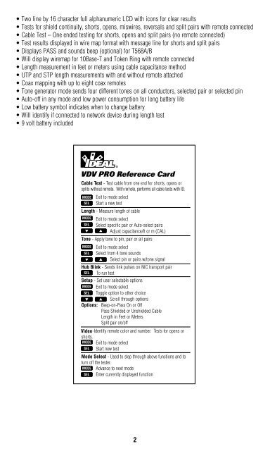
VDV PRO Reference Card<br />
DESCRIPTION<br />
The VDV Pro can be powered on by pressing any of the four buttons. VDV Pro powers off automatically<br />
after 20 minutes of continuous testing of a single cable. Disconnecting the cable restores the tester to<br />
normal function. Most power-on modes will timeout in 20 minutes. The tone mode will power off after<br />
2 1 ⁄ 2 hours. The VDV Pro will turn on in the last mode used before turning off. The back light is toggled<br />
on and off by holding down SEL for 2 seconds or more. At power on, the back light is always on. The<br />
back light turns off automatically 3 minutes after being turned on. (with or without test activity)<br />
Upon completion of the test, the wire map, ID and any faults are displayed.<br />
• The top line of numbers on the display represents the connector pins on the main unit.<br />
• The second line of pin numbers is the connector pin numbers of the remote.<br />
• If there is a miswire, the numbers on the second line will indicate the pin numbers detected.<br />
• If no connection was detected for some of the pins, the second line will be blank in those pin locations.<br />
• If a short is detected, the second line will have a flashing “ ”in that position, and the specific short<br />
condition displayed on the third line. *<br />
• If a split pair is detected, the pins affected will flash on the second display line. The specific split<br />
condition will be displayed on the third line.<br />
• If there are multiple errors to display on the third line, the messages will be displayed in sequence<br />
until all are displayed.<br />
• Under “ID”, the number of the remote being used will be displayed.<br />
There are five modes of operation as described below plus a setup function. In any mode, pressing the<br />
MODE button causes the mode select screen to be displayed. The OFF message is usually the first one<br />
displayed. Continued pressing of the MODE button will cycle through the other modes. Pressing the<br />
SEL button causes the currently displayed mode to be entered.<br />
Cable Test – If there is no remote, press any of the buttons to turn on the VDV Pro. The tester<br />
will then test for shorts, opens, and split pairs. The results are displayed as messages on the LCD.<br />
Whenever a new cable assembly is inserted for testing, press the SEL button to start a new test cycle.<br />
Partial and erroneous results can occur if not done.<br />
Typical Cable Parameters<br />
Cable pF/ft pF/m<br />
Data CAT3 19.0 62.5<br />
CAT5/5E 15.0 49.0<br />
CAT6 15.0 49.0<br />
Coax RG6/U 16.25 53.0<br />
RG11/U 16.25 53.0<br />
RG58/U 27.5 90.0<br />
RG59/U 16.25 53.0<br />
Typical Cable Parameters<br />
Cable pF/ft pF/m<br />
Security Wire<br />
22 AWG, Jacketed 24.0 78.5<br />
22 AWG, Unjacketed 14.0 46.0<br />
20 AWG, Unjacketed 16.0 52.5<br />
18 AWG, Unjacketed 17.0 55.0<br />
Split pair on/off<br />
Length – The length mode measures the length of a cable by measuring its capacitance and using the<br />
capacitance per unit of length (length constant) to calculate the length. The length is displayed on the LCD<br />
along with the current value of the length constant. The SEL button changes the pair being measured in<br />
a 1-2, 3-6, 4-5, 7-8 and auto-select sequence. The pair number is displayed next to the length except<br />
in auto-select mode. If a selected pair has a fault, the fault replaces the length reading on the LCD. In<br />
auto-select mode, the VDV Pro automatically selects a pair without a fault. Use the auto-select or 1-2 pair<br />
settings to measure the length of a coax cable connected to the F-connector. The length<br />
constant is changed with the up and down arrows. The CAL icon is on while adjusting the constant.<br />
Note: If the far end of the cable is connected to a Network Device (Hub, Switch, etc.), the VDV Pro will<br />
display “Network??”.<br />
2<br />
3


