und Bedienungsanleitung für ABUS Fenster-Universalschloss FTS ...
und Bedienungsanleitung für ABUS Fenster-Universalschloss FTS ...
und Bedienungsanleitung für ABUS Fenster-Universalschloss FTS ...

Create successful ePaper yourself
Turn your PDF publications into a flip-book with our unique Google optimized e-Paper software.
D Montage- <strong>und</strong> <strong>Bedienungsanleitung</strong> für <strong>ABUS</strong> <strong>Fenster</strong>-<strong>Universalschloss</strong> <strong>FTS</strong> 96<br />
G <strong>ABUS</strong> Installation and operation instructions for <strong>ABUS</strong> universal window lock <strong>FTS</strong> 96<br />
Abb./fig./<br />
schéma/<br />
afb./ill. 1<br />
D Diese Anleitung ist wie folgt untergliedert:<br />
I. Allgemeine Hinweise IV. Werkzeug<br />
II. Einsatzmöglichkeit V. Montageanleitung<br />
III. Packungsinhalt<br />
VI. Bedienung<br />
I. Allgemeine Hinweise<br />
Das <strong>Fenster</strong>-<strong>Universalschloss</strong> <strong>FTS</strong> 96 ist nach den strengen Prüfanforderungen<br />
der DIN 18104-1 <strong>und</strong> VdS 2536 anerkannt. Durch DIN Certco ist <strong>FTS</strong> 96<br />
zertifiziert „EINBRUCHHEMMEND DIN-geprüft“. <strong>FTS</strong> 96 bietet zusätzlich<br />
Schutz gegen unberechtigtes Eindringen in ihre Räume. Gemäß DIN 18104-1<br />
wird empfohlen, dass pro 1 Meter <strong>Fenster</strong>höhe rechts <strong>und</strong> links jeweils eine<br />
Zusatzsicherung montiert wird (pro <strong>Fenster</strong>). Polizei <strong>und</strong> Versicherer empfehlen<br />
dieses ebenfalls.<br />
Die optimale Schutzwirkung erreichen Sie, wenn Sie entsprechend dieser<br />
Montage- <strong>und</strong> <strong>Bedienungsanleitung</strong> vorgehen.<br />
Die Befestigungsschrauben sollten zur Vermeidung von Überdrehung mit<br />
einem geeigneten Werkzeug eingeschraubt <strong>und</strong> von Hand angezogen werden.<br />
Ausschließlich <strong>ABUS</strong>-Befestigungsmaterial einsetzen.<br />
Für eventuell auftretende Verletzungen bzw. Schäden, die bei der Montage<br />
<strong>und</strong>/oder durch unsachgemäße Handhabung entstehen, übernimmt der<br />
Hersteller keine Haftung!<br />
Ein Zugang des gesamten Objektes muss von außen mittels Schlüssel zu<br />
öffnen sein.<br />
II. Einsatzmöglichkeit<br />
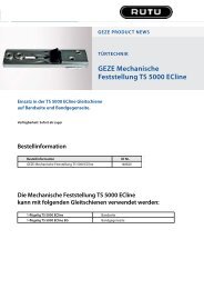
<strong>FTS</strong> 96 wird auf der Griffseite des <strong>Fenster</strong>s oder der <strong>Fenster</strong>tür montiert<br />
<strong>und</strong> eignet sich für alle gängigen nach innen öffnende <strong>Fenster</strong>/<strong>Fenster</strong>türen<br />
mit Dreh- oder -Dreh-Kipp-Beschlägen (Abb. 1). Die Montage kann auf den<br />
Werkstoffen Kunststoff, Holz oder Alu erfolgen. Die <strong>Fenster</strong>/<strong>Fenster</strong>türen<br />
können nach rechts oder links öffnen.<br />
<strong>FTS</strong> 96 wird gr<strong>und</strong>sätzlich auf der Innenseite montiert, der Schlosskasten auf<br />
dem <strong>Fenster</strong>flügel <strong>und</strong> der Schließkasten auf dem Rahmen.<br />
Bei schlechten Befestigungsmöglichkeiten (Weichholz- oder Kunststofffenster)<br />
sollten mehrere Sicherungen <strong>und</strong> zusätzlich Befestigungsmittel (Befestigungsanker<br />
oder Verb<strong>und</strong>mörtel) eingesetzt werden. Hierzu verwenden Sie<br />
bitte den <strong>ABUS</strong>-Befestigungsanker BA (Kunststoff-, Weichholz-, Alufenster)<br />
oder alternativ das <strong>ABUS</strong>-Befestigungsset IM 100 (Kunststofffenster).<br />
Zu IM 100 benötigen Sie einen geeigneten Verb<strong>und</strong>mörtel,<br />
z.B. der Marke Fischer FIS VS 150C, Hilti HFX oder ein ähnliches Produkt.<br />
<strong>ABUS</strong> BA <strong>und</strong> <strong>ABUS</strong> IM 100 sowie Verb<strong>und</strong>mörtel sind im Handel erhältlich.<br />
Die in Abb. 2 zusätzlich gezeigten <strong>ABUS</strong>-Produkte (FAS) sind ebenfalls im<br />
Handel erhältlich.<br />
III. Packungsinhalt (Abb. 3)<br />
1. 1 Schlosskasten<br />
2. 1 Schließkasten<br />
3. 1 Anschraubleiste<br />
4. 1 Abdeckhaube Schlosskasten<br />
5. 1 Abdeckhaube Schließkasten<br />
6. 2 Unterlegscheiben keilförmig<br />
7. 1 Satz Unterlagen für Rahmenleiste je 1x1, 2, 4, 8 mm<br />
8. Schrauben:<br />
8 Stück 5,5 x 60 mm 1 Stück M6 x 35 mm<br />
2 Stück 4,2 x 16 mm 3 Stück M6 x 25 mm<br />
2 Stück 4,2 x 9,5 mm<br />
IV. Montagewerkzeug<br />
Kreuzschlitzschraubendreher<br />
Schlitzschraubendreher<br />
Bohrmaschine<br />
Feile, Säge zum Kürzen der Schrauben, ggf. Schraubstock<br />
1 Inbusschlüssel SW 4<br />
G These instructions are organised in the following sections:<br />
I. General instructions IV. Tools<br />
II. Possible uses V. Installation instructions<br />
III. Pack contents<br />
VI. Operation<br />
I. General instructions<br />
The universal window lock <strong>FTS</strong> 96 is recognised as complying with the<br />
strict test requirements of DIN 18104-1 and VdS 2536.<br />
<strong>FTS</strong> 96 is certified by DIN Certco as “BURGLAR RETARDANT DIN tested”.<br />
<strong>FTS</strong> 96 offers additional protection from unauthorised intruders in your rooms.<br />
DIN 18104-1 recommends that an additional security device should be<br />
fitted on the left and right for every meter in height (per window).<br />
The police and insurance companies also give the same recommendation.<br />
Optimum protection can be achieved by proceeding according to these<br />
installation and operation instructions. To prevent the risk of overtightening,<br />
the fastening screws should by screwed in using a suitable tool and tightened<br />
by hand. Only use <strong>ABUS</strong> fastening material.<br />
The manufacturer does not assume any liability for possible injuries<br />
or damages caused during installation and/or by incorrect handling!<br />
II. Application<br />
<strong>FTS</strong> 96 is mounted on the handle side of the window or French door<br />
and is suitable for all common windows/French doors openingto the<br />
inside with turn or turn-and-tilt hardware (fig. 1).<br />
The lock can be fitted to wood, PVC or aluminium.<br />
The windows/French doors can open to the right or left.<br />
<strong>FTS</strong> 96 is always fitted on the inside, with the lock case on the casement<br />
and the striking plate on the frame.<br />
In poor fixture conditions (soft or hollow or foam base and PVC windows<br />
with and without metal inlay and wooden windows) and/or good possibilities<br />
for intrusion from the outside, more security devices and additional fastenings<br />
should be used (composite mortar or fixing bolts). If the frame itself is too<br />
weak for sensible retrofitting, it may be necessary for example to reinforce the<br />
frame.<br />
To do so, please use the <strong>ABUS</strong> fixing bolt BA or alternatively for PVC frames,<br />
the <strong>ABUS</strong> fastening set IM 100. For IM 100 you need a suitable composite<br />
mortar, e.g. Fischer FIS VS 150C or similar. <strong>ABUS</strong> BA and <strong>ABUS</strong> IM 100 are<br />
available from retail stores together with composite mortar.<br />
The <strong>ABUS</strong> products (FAS) shown in fig. 2 are also available from retail<br />
stores.<br />
III. Pack contents (fig. 3)<br />
1. 1 lock case<br />
2. 1 striking plate<br />
3. 1 screw-on strip<br />
4. 1 cover cap for lock case<br />
5. 1 cover cap for locking case<br />
6. 2 wedge-shaped washers<br />
7. 1 set of spacers for the frame strip 1x1, 2, 4, 8 mm each<br />
8. Screws:<br />
8 each 5.5 x 60 mm<br />
2 each 4.2 x 16 mm<br />
2 each 4.2 x 9,5 mm<br />
1 each M6 x 35 mm<br />
3 each M6 x 25 mm<br />
Abb./fig./<br />
schéma/<br />
afb./ill. 2<br />
4<br />
<strong>FTS</strong><br />
<strong>FTS</strong><br />
1<br />
FAS<br />
FAS<br />
5<br />
<strong>Fenster</strong>flügel<br />
Window<br />
Battant de fenêtre<br />
Raam<br />
Battente<br />
2<br />
3<br />
120<br />
51<br />
FAS<br />
7<br />
51 3 18<br />
<strong>FTS</strong><br />
<strong>FTS</strong><br />
max. 29<br />
28<br />
<strong>Fenster</strong>rahmen<br />
Frame<br />
Cadre<br />
Kozijn<br />
Telaio<br />
IV. Installation tools<br />
Phillips screwdriver<br />
Slotted recess screwdriver<br />
Drill<br />
Saw, file for shortening the screws, possibly vice<br />
1 hex key, width across flats 4<br />
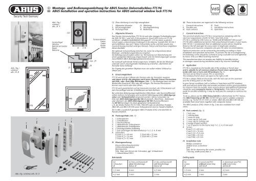
Bohrtabelle<br />
Drilling table<br />
Abb./fig./schéma/afb./ill. 3<br />
6<br />
8<br />
für<br />
Schrauben<br />
Ø<br />
5,5 mm<br />
4,2 mm<br />
In Holz <strong>und</strong> Kunststoff<br />
ohne Metalleinlage<br />
Bohrer Ø<br />
4 mm<br />
3 mm<br />
In Alu <strong>und</strong> Kunststoff<br />
mit Metalleinlage<br />
Bohrer Ø<br />
4,5 mm<br />
3 mm<br />
for<br />
screws<br />
Ø<br />
5.5 mm<br />
4.2 mm<br />
in wood and PVC<br />
without metal inlay<br />
drill bit Ø<br />
4 mm<br />
3 mm<br />
in aluminium and PVC<br />
with metal inlay<br />
drill bit Ø<br />
4.5 mm<br />
3 mm
F Instructions de montage pour serrure<br />
de fenêtre universelle <strong>ABUS</strong> <strong>FTS</strong> 96<br />
n Montage- en gebruiksaanwijzing<br />
voor <strong>ABUS</strong> universeel bijzetslot <strong>FTS</strong> 96<br />
I Istruzioni di montaggio ed uso della<br />
serratura universale per finestre <strong>ABUS</strong> <strong>FTS</strong> 96<br />
classificatie<br />
manuele test<br />
zelfstandig<br />
inbraakwerendheidsklasse<br />
NEN5096/ENV1630<br />
RC 3<br />
contacttijd /<br />
gereedschapsset<br />
5 min. / B<br />
gebruik BA-anker<br />
houten kozijnen kunststof kozijnen<br />
zonder<br />
<strong>ABUS</strong> bevestigingsanker<br />
in combinatie met<br />
<strong>ABUS</strong> bevestigingsanker<br />
F Ce manuel comporte les chapitres suivants:<br />
I. Conseils d’ordre général IV. Outillage<br />
II. Application V. Instructions de montage<br />
III. Liste de colisage<br />
VI. Utilisation<br />
I. Conseils d’ordre général<br />
La serrure de fenêtre universelle <strong>FTS</strong> 96 satisfait aux exigences de contrôle<br />
sévères des normes DIN 18104-1 et VdS 2536. Le certificat DIN indique que<br />
<strong>FTS</strong> 96 a obtenu la qualification «anti-effraction DIN». <strong>FTS</strong> 96 offre en plus<br />
une protection contre les intrusions par effraction dans votre logement.<br />
Selon la norme DIN 18104-1, il est recommandé de monter une sécurité<br />
complémentaire par mètre de hauteur de fenêtre, à gauche comme à droite<br />
(par fenêtre). La police et les compagnies d’assurance le recommandent<br />
également.<br />
Pour un effet de protection optimal, suivez les instructions de ce manuel<br />
d’installation et d’utilisation. Afin d’éviter un serrage abusif, vissez et serrez<br />
les vis de fixation à la main et avec un outillage adéquat. Utilisez exclusivement<br />
des accessoires <strong>ABUS</strong>.<br />
Le fabricant n’assume aucune responsabilité pour d’éventuels blessures<br />
ou dégâts causés pendant l’installation et/ou par suite de manipulations<br />
inappropriées!<br />
L’ensemble doit être accessible de l’extérieur afin de l’ouvrir au moyen<br />
d’une clé.<br />
II. Application<br />
<strong>FTS</strong> 96 est monté du côté de la poignée de la fenêtre ou de la porte-fenêtre<br />
et convient pour toutes les fenêtres/portes-fenêtres courantes, ouvrant vers<br />
l’intérieur et pourvues de quincaillerie battante ou oscillo-battante (schéma 1).<br />
L’installation peut être effectuée sur des châssis en bois, en PVC ou en<br />
aluminium. Les fenêtres/portes-fenêtres peuvent s’ouvrir à gauche ou à droite.<br />
<strong>FTS</strong> 96 est monté en principe du côté intérieur, la gâche sur l’ouvrant et<br />
la serrure sur le dormant.<br />
En cas de possibilités de fixation défavorables (fenêtres en bois ou en PVC),<br />
plusieurs sécurités et des fixations supplémentaires (plots d’ancrage ou<br />
mortier) doivent être prévues.<br />
Pour cela, utilisez l’ancre de fixation <strong>ABUS</strong> BA (pour fenêtres en PVC,<br />
en bois tendre ou en aluminium) ou l’ensemble de fixation <strong>ABUS</strong> IM 100<br />
(pour fenêtres en PVC). Pour IM 100, un mortier approprié est requis, par<br />
exemple FIS VS 150C de la marque Fischer, HFX de la marque Hilti ou un<br />
produit similaire. <strong>ABUS</strong> BA et <strong>ABUS</strong> IM 100 ainsi que le mortier de fixation<br />
sont disponibles dans le commerce.<br />
Les produits <strong>ABUS</strong> complémentaires illustrés en schéma 2 (FAS) sont<br />
également disponibles dans le commerce.<br />
III. Liste de colisage (schéma 3)<br />
1. 1 boîtier<br />
2. 1 gâche<br />
3. 1 platine de fixation<br />
4. 1 cache pour boîtier<br />
5. 1 cache pour gâche<br />
6. 2 entretoises coniques<br />
7. 1 ensemble d’entretoises pour dormant chacun 1x1, 2, 4, 8 mm<br />
8. Vis:<br />
8 pièces 5,5 x 60 mm 1 pièces M6 x 35 mm<br />
2 pièces 4,2 x 16 mm 3 pièces M6 x 25 mm<br />
2 pièces 4,2 x 9,5 mm<br />
IV. Outillage de montage<br />
Tournevis cruciforme<br />
Tournevis plat<br />
Perceuse<br />
Lime, scie pour raccourcir les vis, tournevis<br />
1 clé à six-pans SW 4<br />
Tableau de perçage<br />
n Deze montage- en gebruiksaanwijzing is als volgt onderverdeeld:<br />
I. Algemeen IV. Gereedschap<br />
II. Toepassingsmogelijkheden V. Montage-instructies<br />
III. Verpakkingsinhoud<br />
VI. Gebruik<br />
I. Algemeen<br />
Bijzetgrendel voor naar binnen draaiende draai/kiep elementen.<br />
<strong>FTS</strong> 96 is volgens keuringseisen NEN 5096 SKG gecertificeerd.<br />
De <strong>FTS</strong> 96 biedt daarnaast bescherming tegen onbevoegd binnendringen<br />
van uw woning. Advies: monteer aan de sluitzijde voor maximale veiligheid<br />
2 stuks per 1 meter raamhoogte. Op kunststof zonder metalen kern dient<br />
u dit slot in combinatie met <strong>ABUS</strong> BA bevestigingsanker te monteren.<br />
Optioneel verkrijgbaar, zie voor montage in de handleiding van BA.<br />
Optimale veiligheid wordt bereikt door nauwkeurig opvolgen van deze<br />
montage- en gebruiksaanwijzing. Om overexpansie of doldraaien van de<br />
bevestigingsschroeven te vermijden, draait u handmatig en met passend<br />
gereedschap de schroeven vast.<br />
Voor eventueel verwondingen en/of schade tijdens montage en/of<br />
door ondesk<strong>und</strong>ig gebruik ontstaan, aanvaardt de fabrikant geen<br />
aansprakelijkheid!<br />
II. Toepassingsmogelijkheden<br />
De <strong>FTS</strong> 96 wordt aan de sluitzijde van het raam of deur gemonteerd en<br />
is geschikt voor alle gangbare naar binnen draaiende ramen en deuren<br />
met draai(/kiep)-beslag (afb. 1). De montage kan op de materialen hout,<br />
kunststof of aluminium worden uitgevoerd. De ramen/deuren kunnen naar<br />
rechts of links opengaan.<br />
<strong>FTS</strong> 96 wordt principe uitsluitend ann de binnenkant gemonteerd;<br />
de slotkast op het raam of de deur en de sluitkast op het kozijn.<br />
Bij slechte bevestigingsmogelijkheden (zacht hout of kunststof) dienen<br />
meerdere beveiligingen en extra beveiligingsmaterialen te worden toegepast.<br />
Hiervoor kunt u het <strong>ABUS</strong>-bevestigingsanker BA (zacht hout, kunststof,<br />
aluminium) of de <strong>ABUS</strong>-bevestigingsset IM 100 (kunststof) gebruiken.<br />
Voor de IM 100 heeft u een geschikt chemisch anker, bijv. Fischer FIS VS 150C,<br />
Hilti HFX of vergelijkbaar. <strong>ABUS</strong> BA, <strong>ABUS</strong> IM 100 en chemische ankers zijn<br />
in de handel verkrijgbaar.<br />
De in afb. 2 weergegeven <strong>ABUS</strong>-producten (FAS) zijn ook in de handel<br />
verkrijgbaar.<br />
III. Verpakkingsinhoud (afb. 3)<br />
1. 1 slotkast<br />
2. 1 sluitkast<br />
3. 1 montageplaat<br />
4. 1 afdekkap slotkast<br />
5. 1 afdekkap sluitkast<br />
6. 2 wigvormige opvulringen<br />
7. 1 set opvulplaatjes 1x1, 2, 4, 8 mm (elk 1 stuk)<br />
8. Schroeven/bouten:<br />
8 stuks 5,5 x 60 mm<br />
2 stuks 4,2 x 16 mm<br />
2 stuks 4,2 x 9,5 mm<br />
1 stuks M6 x 35 mm<br />
3 stuks M6 x 25 mm<br />
IV. Montagegereedschap<br />
Kruiskopschroevendraaier<br />
Sleufschroevendraaier<br />
Boormachine<br />
Vijl, zaag voor het inkorten van de schroeven, evt. bankschroef<br />
1 inbussleutel 4 mm<br />
Boortabel<br />
I Queste istruzioni si suddividono nel modo seguente:<br />
I. Istruzioni generali IV. Attrezzi<br />
II. Possibilità d´impiego V. Istruzioni di montaggio<br />
III. Contenuto della confezione VI. Uso<br />
I. Istruzioni generali<br />
La sicura per cerniere di finestre <strong>FTS</strong> 96 è conforme ai severi requisiti<br />
di controllo della DIN 18104-1 e della VdS 2536.<br />
Con la DIN Certco essa è certificata come «ANTISCASSO conf. DIN».<br />
La <strong>FTS</strong> 96 garantisce una protezione in più a difesa della Vostra casa.<br />
Secondo DIN 18104-1 si consiglia di montare per ogni metro di altezza<br />
della finestra, una sicura supplementare sul lato destro e una sul lato<br />
sinistro (per ogni finestra). Anche la polizia e le compagnie d’assicurazione<br />
consigliano tali misure.<br />
Si può ottenere una protezione ottimale, procedendo secondo queste istruzioni<br />
di montaggio ed uso. Le viti di fissaggio, per evitarne un serraggio eccessivo,<br />
devono essere avvitate con un utensile adatto e poi serrate a mano.<br />
Impiegare esclusivamente materiale di fissaggio <strong>ABUS</strong>.<br />
Per eventuali ferimenti e/o danni, che si verificano durante il montaggio e/o<br />
per maneggio indebito, il produttore non si assume alcuna responsabilità!<br />
II. Possibilità d’impiego<br />
La <strong>FTS</strong> 96 viene montata sul lato della cerniera della finestra o della portafinestra<br />
ed è adatta per tutte le normali finestre e porte-finestre che si<br />
aprono verso l’interno, con ferramenti girevoli o girevoli- a bilico (ill. 1).<br />
Si può montare la <strong>FTS</strong> 96 su legno, plastica o alluminio.<br />
Le finestre/porte-finestre possono aprirsi verso destra o verso sinistra.<br />
Di solito la <strong>FTS</strong> 96 viene montata all’interno, la lamiera del battente<br />
sul battente della finestra ed il listello del telaio sul telaio.<br />
Se le possibilità di fissaggio sono scadenti (sottofondo morbido o vuoto<br />
o riempito con espanso e finestre in plastica con o senza inserto metallico<br />
e finestre in legno) e le possibilità di effrazione dall’esterno sono buone,<br />
si dovrebbero utilizzare più sicure e mezzi di fissaggio supplementari<br />
(malta o avvitamento passante o bullone di fissaggio).<br />
Se i telai stessi sono troppo deboli, per poterli allestire adeguatamente<br />
in un secondo tempo, potrebbe essere consigliabile rinforzare, per esempio,<br />
i telai stessi.<br />
Allo scopo utilizzare per favore il bullone di fissaggio <strong>ABUS</strong> BA o come<br />
alternativa, nel caso di telai in plastica, il kit di fissaggio <strong>ABUS</strong> IM 100.<br />
Per il IM 100 serve una malta adatta, p.e. della marca Fischer FIS VS 150C<br />
o un prodotto simile. <strong>ABUS</strong> BA e <strong>ABUS</strong> IM 100 come anche la malta si possono<br />
acquistare.<br />
I prodotti <strong>ABUS</strong> mostrati inoltre nel’ill. 2 (FAS) sono anche reperibili in<br />
commercio.<br />
III. Contenuto della confezione (ill. 3)<br />
1. 1 scatola della serratura<br />
2. 1 cassa della serratura<br />
3. 1 listello da avvitare<br />
4. 1 coperchietto della scatola della serratura<br />
5. 1 coperchietto della cassa della serratura<br />
6. 2 rondelle cuneiformi<br />
7. 1 kit di spessori per listello del telaio 1x1, 2, 4, 8 mm ciascuno<br />
8. Viti:<br />
2 viti da 5,5 x 60 mm 1 vite M6 x 35 mm<br />
2 viti da 4,2 x 16 mm 3 viti M6 x 25 mm<br />
2 viti da 4,2 x 9,5 mm<br />
IV. Attrezzi da montaggio<br />
cacciavite a croce<br />
cacciavite per viti a testa intagliata<br />
tarpano<br />
lima, sega per accorciare le viti, in caso morsa<br />
1 chiave ad esagono incassato SW 4<br />
Tabella di trapanazioni<br />
pour<br />
vis<br />
de Ø<br />
dans châssis bois et PVC<br />
sans armature métallique<br />
foret Ø<br />
dans châssis aluminium et PVC<br />
avec armature métallique<br />
foret Ø<br />
voor<br />
schroeven<br />
Ø<br />
in hout en kunststof<br />
zonder metalen kern<br />
boor Ø<br />
in aluminium en kunststof<br />
met metalen kern<br />
boor Ø<br />
per<br />
viti<br />
Ø<br />
in legno e plastica<br />
senza inserto metallico<br />
punta da trapano Ø<br />
in alluminio e plastica<br />
con inserto metallico<br />
punta da trapano Ø<br />
5,5 mm<br />
4 mm<br />
4,5 mm<br />
5,5 mm<br />
4 mm<br />
4,5 mm<br />
5,5 mm<br />
4 mm<br />
4,5 mm<br />
4,2 mm<br />
3 mm<br />
3 mm<br />
4,2 mm<br />
3 mm<br />
3 mm<br />
4,2 mm<br />
3 mm<br />
3 mm
Abb./fig./schéma/afb./ill. 4<br />
Falzhöhe<br />
Rebate height<br />
Recouvrement<br />
Opdekmaat<br />
Altezza<br />
d’incassatura<br />
0 – 29 mm<br />
Abb./fig./<br />
schéma/<br />
afb./ill. 5<br />
Schließkasten<br />
Locking case<br />
Gâche<br />
Sluitkast<br />
Scatola della<br />
serratura<br />
Rahmen<br />
Frame<br />
Cadre<br />
Kozijn<br />
Telaio<br />
Abb./fig./<br />
schéma/<br />
afb./ill. 6<br />
2 mm<br />
3 mm<br />
2 mm<br />
Abb./fig./<br />
schéma/<br />
afb./ill. 7<br />
A<br />
A<br />
Unterlagen für Höhenausgleich<br />
Spacers<br />
Entretoises<br />
Opvulplaatjes<br />
Spessori da livellamento<br />
Tür bzw. <strong>Fenster</strong><br />
Door/Window<br />
Fenêtre<br />
Deur/Raam<br />
Porta risp. Finestra<br />
Schlosskasten<br />
Lock case<br />
Boîtier<br />
Slotkast<br />
Cassa della serratura<br />
C<br />
B<br />
B<br />
C<br />
Abb./fig./<br />
schéma/<br />
afb./ill. 8<br />
3 mm<br />
D V. Montageanleitung:<br />
Wichtige Hinweise:<br />
1. Vor der Montage prüfen Sie bitte die Einstellung des <strong>Fenster</strong>s bzw.<br />
der <strong>Fenster</strong>tür. Stellen Sie sicher, dass sich das <strong>Fenster</strong>/die <strong>Fenster</strong>tür<br />
einwandfrei öffnen <strong>und</strong> schließen lässt.<br />
2. Messen Sie auch nach, ob die in Abb. 1 angegebenen Mindestmaße<br />
an Ihrem <strong>Fenster</strong>/Ihrer <strong>Fenster</strong>tür vorhanden sind.<br />
3. Die Bohrlochtiefen bzw. die Schraubenlängen müssen auf die<br />
örtlichen Gegebenheiten abgestimmt werden.<br />
4. Austreten des Bohrers bzw. der Schrauben auf der Rückseite<br />
vermeiden! Ggf. mit Bohranschlag arbeiten oder die vorhandenen<br />
Schrauben kürzen. Beim Bohren keine beweglichen Teile, Dichtungen<br />
oder Glasscheiben verletzen.<br />
Montage:<br />
Montage des Schlosskastens:<br />
1. Abdeckhaube (4) vom Schlosskasten (1) durch Druck auf Rastpunkte<br />
von unten entfernen (s. Abb. 5). Riegel ausschließen.<br />
2. Schlosskasten (1) in gewünschter Position auf <strong>Fenster</strong>flügel bzw.<br />
Türblatt anhalten, Abstand zur Kante 2 mm (s. Abb. 6).<br />
3. Bohrposition A <strong>und</strong> B (nur bei Kunststofffenstern <strong>und</strong> -türen zusätzlich C)<br />
anzeichnen <strong>und</strong> vorbohren (s. Abb. 7 <strong>und</strong> Bohrtabelle).<br />
4. Schlosskasten (1) anschrauben. Bohrungen A (je nach Falzhöhe)<br />
Schrauben 4,2 x 16 mm oder 4,2 x 9,5 mm (Schraubendreher mit<br />
Magnetspitze verwenden). Bohrungen B (C) Schrauben 5,5 x 60 mm.<br />
Montage des Schließkastens:<br />
Schlosskasten (1) <strong>und</strong> Schließkasten (2) müssen auf gleicher Ebene<br />
liegen (s. Abb. 4). Zum Ausgleich der unterschiedlichen Falzhöhen wird<br />
der Schließkasten (2) unterlegt. Hierzu dienen die Anschraubleiste (3)<br />
<strong>und</strong>/oder die Unterlagen (7).<br />
Falzhöhe: ab 14 mm [mit Anschraubleiste (3) <strong>und</strong> ggf. Unterlagen (7)].<br />
1. Anschraubleiste (3) (14 mm hoch) mittig auf gleiche Höhe <strong>und</strong> im parallelen<br />
Abstand von 3 mm zum Schlosskasten (1) anhalten (s. Abb. 8).<br />
Auf richtige Lage der Anschraubleiste (3) achten (s. Abb. 8 <strong>und</strong> 9).<br />
2. Bohrpositionen C1 <strong>und</strong> C2 anzeichnen <strong>und</strong> vorbohren (s. Abb. 9 <strong>und</strong><br />
Bohrtabelle).<br />
3. Anschraubleiste (3) bei Bedarf (Falzhöhe größer 14 mm) mit Unterlagen<br />
(7) unterfüttern. Mit Schrauben 5,5 x 60 mm festschrauben.<br />
4. Durch die schrägen Schraubenlöcher D im gleichen Winkel zur Wand hin<br />
schräg vorbohren (s. Bohrtabelle). Wenn dieses nicht möglich ist, so kann<br />
auch senkrecht gebohrt werden. Dann in Bohrungen D die beiden keilförmigen<br />
Unterlegscheiben (6) einlegen.<br />
5. In Bohrungen D2 weitere Schrauben 5,5 x 60 mm einschrauben.<br />
6. Abdeckhaube (5) vom Schließkasten (2) durch Druck auf Rastpunkte<br />
von unten entfernen (s. Abb. 10).<br />
7. Schließkasten (2) mit 3 Schrauben M6 x 25 mm auf die Anschraubleiste<br />
(3) schrauben.<br />
G V. Installation instructions:<br />
• Before installation, please check the setting of the window<br />
or French door.<br />
• If necessary, readjust the fittings so that the window (French door)<br />
opens and closes perfectly.<br />
• Also check whether your window/French door complies with the<br />
minimum dimensions shown in fig. 1.<br />
• The depths of the drilled holes and screw lengths must be adjusted<br />
to the local conditions.<br />
• Avoid the drill or screws from coming out at the back!<br />
Possibly work with drill stopper or shorten the existing screws.<br />
• When drilling, do not damage any moving parts, seals or glass panes.<br />
Installation:<br />
Fitting the lock case:<br />
1. Remove the cover cap (4) from the lock case (1) from below by pressing<br />
on the catch points (see fig. 5). Undo the locking bolt.<br />
2. Hold the lock case (1) in the required position against the window<br />
casement or door, at a distance of 2 mm to the edge (see fig. 6).<br />
3. Mark and pre-drill hole position A and B (for PVC windows and doors<br />
also C) (see fig. 7 and drilling table).<br />
4. Screw on lock case (1). For holes A (depending on rebate height),<br />
use screws 4.2 x 16 mm or 4.2 x 9.5 mm (screwdriver with magnetic tip).<br />
Holes B (C) screws 5.5 x 60 mm.<br />
Fitting the striking plate:<br />
The lock case (1) and striking plate (2) must be on the same level<br />
(see fig. 4). To compensate for the differing rebate heights,<br />
the striking plate (2) is lined, using the screw-on strip (3) and/or the<br />
spacers (7).<br />
Rebate height: from 14 mm [with screw-on strip (3) and possibly<br />
shims (7)].<br />
1. Hold the screw-on strip (14 mm high) on the same level and at a parallel<br />
distance of 3 mm to the lock case (1) (see fig. 8). Ensure that the screw-on<br />
strip (3) is in the right position (see fig. 8 and 9).<br />
2. Mark and pre-drill bore holes C1 and C2 (see fig. 9 and drilling table).<br />
3. Line screw-on strip (3) with spacers (7) if necessary (rebate height larger<br />
than 14 mm). Screw tight with screws 5.5 x 60 mm.<br />
4. Drill in the middle through the slanting screw holes D at the same<br />
angle to the wall (see drilling table). If this is not possible, drill vertically.<br />
Then place the two wedge-shaped washers (6) in holes D.<br />
5. Screw 2 more screws 5.5 x 60 mm into holes D.<br />
6. Remove the cover cap (5) from the striking plate (2) from below by<br />
pressing on the catch points (see fig. 10).<br />
7. Screw striking plate (2) to screw-on strip with 3 screws M6 x 25 mm.<br />
Check function:<br />
Locking bolt must run freely into the striking plate (2) when closing.<br />
Abb./fig./<br />
schéma/<br />
afb./ill. 9<br />
D<br />
C1<br />
Abb./fig./<br />
schéma/<br />
afb./ill. 10<br />
Abb./fig./<br />
schéma/<br />
afb./ill. 11<br />
3 mm<br />
Abb./fig./<br />
schéma/<br />
afb./ill. 12<br />
E2<br />
E1<br />
Funktion prüfen:<br />
Riegel müssen beim Einschließen in den Schließkasten (2) frei laufen.<br />
8. Beide Abdeckhauben aufdrücken.<br />
Falzhöhe: 0 bis 13 mm (ggf. mit Unterlagen).<br />
1. Abdeckhaube (5) vom Schließkasten (2) durch Druck auf Rastpunkte<br />
von unten entfernen (s. Abb. 10).<br />
2. Schließkasten (2) mittig auf gleicher Höhe <strong>und</strong> im parallelen Abstand<br />
von 3 mm vom Schlosskasten (1) anhalten (s. Abb. 11).<br />
3. Bohrposition E1 bis E3 anzeichnen (s. Abb. 12) <strong>und</strong> vorbohren<br />
(s. Bohrtabelle).<br />
4. Schließkasten (2) bei Bedarf mit Unterlagen (7) unterfüttern <strong>und</strong> mit<br />
3 Schrauben 5,5 x 60 mm festschrauben.<br />
8. Press on both cover caps.<br />
Rebate height: 0 to 13 mm (possibly with shims).<br />
1. Remove the cover cap (5) from the striking plate (2) from below<br />
by pressing on the catch points (see fig. 10).<br />
2. Hold striking plate (2) centrally on the same level and at a parallel<br />
distance of 3 mm to the lock case (1) (see fig. 11).<br />
3. Mark and pre-drill holes position E1 to E3 (see fig. 12)<br />
(see drilling table).<br />
4. Line striking plate (2) with spacers (7) if necessary and screw tight with<br />
3 screws 5.5 x 60 mm.<br />
Check function:<br />
Locking bolt must run freely into the striking plate (2) when closing.<br />
D<br />
C2<br />
E3<br />
Funktion prüfen:<br />
Riegel müssen beim Einschließen in den Schließkasten (2) frei laufen.<br />
5. Beide Abdeckhauben aufdrücken.<br />
VI. Bedienung<br />
<strong>FTS</strong> 96 lässt sich ohne Schlüssel durch Drehen des Knopfes<br />
verschließen. Zum Öffnen wird der Schlüssel benutzt.<br />
5. Press on both cover caps.<br />
VI. Operation<br />
<strong>FTS</strong> 96 can be locked without a key by turning the knob.<br />
Open with the key.<br />
<strong>ABUS</strong> - Das gute Gefühl der Sicherheit<br />
www.abus.com<br />
D Technische Änderungen vorbehalten. Für Irrtümer <strong>und</strong> Druckfehler keine Haftung. <strong>ABUS</strong> © 2010<br />
G Subject to technical alterations. No liability for mistakes and printing errors. <strong>ABUS</strong> © 2010
F V. Instructions de montage:<br />
n V. Montage-instructies:<br />
I V. Istruzioni per il montaggio:<br />
Indications importantes:<br />
1. Avant l’installation, contrôlez le réglage de la fenêtre ou de la<br />
porte-fenêtre. Assurez-vous que la fenêtre/porte-fenêtre ouvre et<br />
ferme parfaitement.<br />
2. Vérifiez si votre fenêtre/porte-fenêtre comporte les dimensions<br />
minimales indiquées en schéma 1.<br />
3. Les profondeurs de perçage ou les longueurs de vis doivent être<br />
adaptées aux conditions locales.<br />
4. Evitez le dépassement de perçage ou de vis sur la face arrière!<br />
Utilisez le cas échéant une butée de perçage ou raccourcissez les<br />
vis de fixation. Lors du perçage, évitez d’endommager les éléments<br />
mobiles, les joints ou les vitres.<br />
Montage du boîtier:<br />
1. Déposez le cache du boîtier (1) par le bas en appuyant sur des points<br />
d’appui (voir schéma 5). Déverrouillez les pênes.<br />
2. Maintenez le boîtier (1) dans la position désirée sur le vantail ou sur<br />
l’encadrement la fenêtre. Distance du bord 2 mm (voir schéma 6).<br />
3. Tracez et préforez les fixations de vis A et B (et C, uniquement sur des<br />
fenêtres et portes-fenêtres en PVC) (voir schéma 7 et tableau de perçage).<br />
4. Fixez le boîtier (1). Fixations de vis A: (en fonction de la hauteur<br />
de rainure) vis de 4,2 x 16 mm ou de 4,2 x 9,5 mm (utilisez un tournevis<br />
à tête aimantée). Fixations de vis B (C ): vis de 5,5 x 60 mm.<br />
Montage de la gâche:<br />
Le boîtier (1) et la gâche (2) doivent se trouver à la même hauteur<br />
(voir schéma 4). Pour égaliser les différentes hauteurs du recouvrement<br />
la gâche (2) doit être rehaussé. C’est à cela que servent la platine<br />
de fixation (3) et/ou les entretoises (7).<br />
Recouvrement: supérieure à 14 mm [avec platine de fixation (3) et<br />
éventuellement des entretoises (7)].<br />
1. Maintenez la platine de fixation (3) (d’une hauteur de 14 mm) centrée,<br />
à la même hauteur et à une même distance de 3 mm en parallèle au<br />
boîtier (1) (voir schéma 8). Assurez-vous de la bonne position de la<br />
platine de fixation (3) (voir schéma 8 et 9).<br />
2. Tracez et préforez les fixations de vis C1 et C2 (voir schéma 9 et tableau<br />
de perçage).<br />
3. Rehaussez selon les besoins (profondeur de rainure supérieure à 14 mm)<br />
la platine de fixation (3) au moyen des entretoises (7). Fixez-la avec des<br />
vis de 5,5 x 60 mm.<br />
4. Préforez de biais dans le même angle et au travers des fixations de vis D<br />
dans la paroi (voir tableau de perçage). Si cela s’avère impossible,<br />
forez dans le sens perpendiculaire. Dans ce cas, posez les entretoises<br />
coniques (6) dans les trous de fixation D.<br />
5. Installez d’autres vis de 5,5 x 60 mm dans les fixations D2.<br />
6. Déposez le cache (5) de la gâche (2) par le bas en appuyant sur les points<br />
d’appui (voir schéma 10).<br />
7. Fixez la gâche (2) sur la platine de fixation (3) avec 3 vis M6 x 25 mm.<br />
Contrôlez le bon fonctionnement: Lors de la fermeture,<br />
les pênes doivent coulisser librement dans le boîtier de gâche (2).<br />
8. Clipsez les deux caches.<br />
Recouvrement: 0 –13 mm (éventuellement avec entretoises)<br />
1. Déposez le cache (5) de la gâche (2) par le bas en appuyant sur des<br />
points d’appui (voir schéma 9).<br />
2. Maintenez la platine de fixation (2) centrée, à la même hauteur et à une<br />
même distance de 3 mm en parallèle au boîtier (1) (voir schéma 11).<br />
3. Tracez les fixations de vis E1 à E3 (voir schéma 12) et préforez<br />
(voir tableau de perçage).<br />
4. Ajustez la hauteur de la gâche (2) selon les besoins avec des<br />
entretoises (7) et fixez-le avec 3 vis de 5,5 x 60 mm.<br />
Contrôlez le bon fonctionnement: Lors de la fermeture,<br />
les pênes doivent coulisser librement dans la gâche (2).<br />
5. Clipsez les deux caches.<br />
VI. Utilisation: La fermeture de <strong>FTS</strong> 96 s’effectue sans clé,<br />
en tournant le bouton. Pour l’ouverture, la clé est requise.<br />
Belangrijke opmerkingen:<br />
• Voor de montage dient u de afstelling van het raam resp. deur<br />
te controleren. Stel evt. het beslag opnieuw in, zodat het correct<br />
functioneert.<br />
• Meet ook na of de in afb. 1 aangegeven minimum afmetingen<br />
daadwerkelijk op uw raam/deur beschikbaar zijn.<br />
• De boordieptes en schroeflengtes moeten aan het gevelelement<br />
aangepast worden.<br />
• Voorkom doorboren en/of -schroeven. Evt. met een booraanslag<br />
werken, kortere schroeven kopen of inkorten. Bij het boren geen<br />
bewegende delen, afdichtingen of glas beschadigen.<br />
Montage van de slotkast:<br />
1. De afdekkap (4) van de slotkast (1) door druk op de vergrendelingspunten<br />
van onder af verwijderen (zie afb. 5). Schoten uit de slotkast draaien.<br />
2. Slotkast (1) op de gewenste positie op het raam/de deur plaatsen.<br />
Afstand t.o.v. de raamkant resp. deurkant 2 mm (zie afb. 6).<br />
3. Boorpositie A en B (bij kunststof ook C) aftekenen en voorboren<br />
(zie afb. 7 en boortabel).<br />
4. Slotkast (1) monteren. Boorgaten A (afhankelijk van de opdekmaat)<br />
met schroeven 4,2 x 16 mm of 4,2 x 9,5 mm (schroevendraaier met<br />
magneetpunt gebruiken) / boorgaten B (C) met schroeven 5,5 x 60 mm.<br />
Montage van de sluitkast:<br />
Slotkast (1) en sluitpkast (2) moeten op hezelfde niveau liggen<br />
(zie afb. 4). Ter compensatie van de verschillende opdekmaten wordt<br />
de sluitkast (2) opgevuld. Hiervoor dient de montageplaat (3) en evt.<br />
opvulplaatjes (7).<br />
Opdekmaat > 14 mm<br />
1. Montageplaat (3) (14 mm) in het midden op dezelfde hoogte en op<br />
3 mm afstand evenwijdig aan de slotkast (1) tegen het kozijn plaatsen<br />
(zie afb. 8). Op de juiste positie van de montageplaat (3) letten<br />
(zie afb. 8 en 9).<br />
2. Boorgaten C1 en C2 aftekenen en voorboren (zie afb. 9 en boortabel).<br />
3. Montageplaat (3) indien nodig (opdekmaat > 14 mm) met opvulplaatjes<br />
(7) uitvullen en m.b.v. de schroeven 5,5 x 60 mm monteren.<br />
4. De schuine schroefgaten D in dezelfde hoek voorboren (zie boortabel).<br />
Wanneer een schuine schroefverbinding niet mogelijk is,<br />
kan m.b.v. de wigvormige opvulringen (6) in de schroefgaten D ook<br />
recht worden geschroefd.<br />
5. In de boorgaten D2 nog meer schroeven 5,5 x 60 mm monteren.<br />
6. Afdekkap (5) van de sluitplaat (2) door druk op de vergrendelingspunten<br />
van onder af verwijderen (zie afb. 10).<br />
7. Sluitplaat (2) m.b.v. 3 bouten M6 x 25 mm op de montageplaat<br />
monteren (3).<br />
Werking controleren:<br />
De schoten moeten bij het vergendelen vrij in de sluitplaat (2) lopen.<br />
8. Afdekkappen op de slot- en sluitkast drukken.<br />
Opdekmaat 0 tot 13 mm<br />
1. Afdekkap (5) van de sluitkast (2) door druk op de vergrendelingspunten<br />
van onder af verwijderen (zie afb. 10).<br />
2. Sluitplaat (2) in het midden op dezelfde hoogte en op 3 mm afstand<br />
evenwijdig aan de slotkast (1) tegen het kozijn (zie afb. 11).<br />
3. Boorpositie E1 tot E3 aftekenen (zie afb. 12) en voorboren (zie boortabel).<br />
4. Sluitkast (2) indien nodig met opvulplaatjes (7) uitvullen en m.b.v.<br />
3 schroeven 5,5 x 60 mm monteren.<br />
Werking controleren:<br />
De schoten moeten bij het vergendelen vrij in de sluitplaat (2) lopen.<br />
5. Afdekkappen op de slot- en sluitkast drukken.<br />
VI. Gebruik<br />
<strong>FTS</strong> 96 kan zonder sleutel m.b.v. de draaiknop vergrendeld worden.<br />
Voor het ontgrendelen is de sleutel nodig.<br />
Avvertenze importanti:<br />
• Prima del montaggio verificare per favore la regolazione della<br />
finestra risp. della porta finestra.<br />
• Se necessario registrare nuovamente i ferramenti affinché la<br />
finestra (la porta-finestra) si chiuda e si apra perfettamente.<br />
• Verificare anche che le misure minime indicate nell’ill. 1 esistano<br />
nelle vostre finestre/ porte-finestre.<br />
• Le profondità per trapanare i fori, risp. le lunghezze delle viti<br />
devono essere adattate alle condizioni particolari.<br />
• Evitare che la punta del trapano risp. la vite fuoriesca dall’altra<br />
parte!<br />
Se necessario lavorare con arresto del trapano o accorciare le viti.<br />
• Quando si trapana, non danneggiare parti mobili, guarnizioni<br />
o vetri.<br />
Montaggio:<br />
Montaggio della scatola della serratura:<br />
1. Togliere il coperchietto (4) dalla scatola della serratura (1) premendo<br />
sui punti di incastro dal basso (vedi ill. 5). Aprire il chiavistello.<br />
2. Tenere la scatola della serratura (1) nella posizione desiderata sul<br />
battente della finestra risp. della porta, distanza dal bordo 2 mm<br />
(vedi ill. 6).<br />
3. Disegnare fori di trapanazione A e B (con finestre e porte in plastica<br />
anche C) e trapanare (vedi ill. 7 e tabella trapanazioni).<br />
4. Avvitare la scatola della serratura (1). Fori A (secondo altezza d’incastro)<br />
viti 4,2 x 16 mm o 4,2 x 9,5 mm (usare cacciavite con punta magnetica).<br />
Fori B (C) viti 5,5 x 60 mm.<br />
Montaggio della cassa della serratura:<br />
Scatola della serratura (1) e cassa della serratura (2) devono stare sullo<br />
stesso livello (vedi ill. 4) Per compensare le diverse altezze di incastro,<br />
sotto la cassa della serratura (2) si mettono spessori.<br />
Allo scopo si utilizzano il listello da avvitare (3) e/o gli spessori (7).<br />
Altezza d’incassatura: a partire da 14 mm<br />
[con listello da avvitare (3) e in caso spessori (7)].<br />
1. Avvitare il listello (3) (alto 14 mm) centrato alla stessa altezza e tenere a<br />
distanza parallela di 3 mm rispetto alla scatola della serratura (1)<br />
(vedi ill. 8). Fare attenzione alla giusta posizione del listello da avvitare (3)<br />
(vedi ill. 8 e 9).<br />
2. Disegnare le posizioni da trapanare C1 e C2 (vedi ill. 9 e tabella<br />
trapanazioni).<br />
3. Se necessario (altezza d’incastro superiore a 14 mm) mettere sotto<br />
il listello da avvitare degli spessori (7). Avvitare saldamente con<br />
viti 5,5 x 60 mm.<br />
4. Trapanare attraverso i fori obliqui per le viti D con la stessa angolatura,<br />
obliquamente rispetto alla parete (vedi tabella trapanazioni).<br />
Se non fosse possibile, si può trapanare anche perpendicolarmente.<br />
Poi mettere nei fori D le due rondelle a cuneo (6).<br />
5. Nei fori D2 avvitare altre viti 5,5 x 60 mm.<br />
6. Rimuovere il coperchietto (5) dalla cassa della serratura (2) premendo sui<br />
punti di incastro dal basso (vedi ill. 10).<br />
7. Avvitare la cassa della serratura (2) con 3 viti M 6x 25 al listello (3).<br />
Controllare il funzionamento: I chiavistelli devono poter scorrere<br />
liberamente quando si chiudono nella cassa della serratura (2).<br />
8. Applicare premendo i due coperchietti (4 e 5).<br />
Altezza di incastro: da 0 a 13 mm (se necessario con spessori).<br />
1. Rimuovere il coperchietto (5) dalla cassa della serratura (2) premendo sui<br />
punti di incastro dal basso (vedi ill. 10).<br />
2. Tenere la cassa della serratura (2) centrata alla stessa altezza e a distanza<br />
parallela di 3 mm dalla scatola della serratura (1) (vedi ill. 11).<br />
3. Disegnare posizioni di trapanazione da E1 a E3 (vedi ill. 12) e trapanare<br />
(vedi tabella trapanazioni).<br />
4. Se necessario mettere sotto alla cassa della serratura (2) spessori (7)<br />
e avvitare saldamente con 3 viti 5,5 x 60 mm.<br />
Controllare il funzionamento: I chiavistelli devono poter scorrere<br />
liberamente quando si chiudono nella cassa della serratura (2).<br />
5. Applicare premendo i due coperchietti (4 e 5).<br />
VI. Uso<br />
<strong>FTS</strong> 96 si può chiudere senza chiave, girando il pomello<br />
(in caso impostare il codice). Per aprire, si usa la chiave.<br />
www.abus.com<br />
390104 12/10<br />
F Nous nous réservons le droit de toutes modifications techniques. Nous n’assumons aucune responsabilité pour des erreurs ou défauts d’impression éventuels. <strong>ABUS</strong> © 2010<br />
n Technische wijzigingen voorbehouden. Geen aansprakelijkheid voor vergissingen en drukfouten. <strong>ABUS</strong> © 2010<br />
I Ci si riservano modifiche tecniche. Per errori e refusi di stampa non ci si assume alcuna responsabilità. <strong>ABUS</strong> © 2010