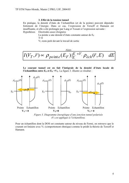
<strong>TP</strong> <strong>STM</strong> Nano-Mon<strong>de</strong>, Master 2 PRO, UJF, 2004/053. Effet <strong>de</strong> la tension tunnelEn pratique, la <strong>de</strong>nsité d’états <strong>de</strong> l’échantillon (et <strong>de</strong> la pointe) peuvent dépendrefortement <strong>de</strong> l’énergie. Dans ce cas, l’expression <strong>de</strong> Tersoff et Hamann estinsuffisante, et elle a été prolongée par Lang et Tossati à l’expression suivante :Hypothèses Electro<strong>de</strong>s assez éloignéesLa pointe a une <strong>de</strong>nsité d’états constante autour <strong>de</strong> E FT=0V T reste petit <strong>de</strong>vant le travail <strong>de</strong> sortieIAlorsV r EE V F TT , ) ∝ ρ po e(F )+∫ ρéch(r,E)( intEFdELe courant tunnel est en fait l’intégrale <strong>de</strong> la <strong>de</strong>nsité d’états locale <strong>de</strong>l’échantillon entre E F et E F +V T . La figure 3. illustre ce résultat :ρpointe( E)ρ éch (E)ρ ( E)ρ )( E)pointeéch (Eρ po inteρ éch (E)eV TE FPointe EchantillonE FE FE FPointe EchantilloneV TV T < 0Pointe EchantillonV T =0V T > 0Figure 3. Diagramme énergétique d’une jonction tunnel polarisée(V T est appliqué à l’échantillon).Pour un échantillon dont la DOS est constante autour du niveau <strong>de</strong> Fermi, on retrouve que lecourant est linéaire avec V T (comportement ohmique) comme le prédit la théorie <strong>de</strong> Tersoff etHamann.4
<strong>TP</strong> NanoMon<strong>de</strong>, Master 2 PRO UJF Année 2004/05Présentation et fonctionnement du <strong>STM</strong>Practical presentation of the <strong>STM</strong> microscopeThe microscope used for this practical work is a commercial <strong>STM</strong> from Easyscan, sold by theNanosurf Company.In general the <strong>STM</strong> microscope contains three parts: the head, the electronic module and thesoftware control.1/ <strong>STM</strong> headThe microscope head is composed by a rigid part where is fixed one or severalpiezoelectric ceramics. A piezoelectric material has the property to <strong>de</strong>form itself when it issubmitted to an external electrical field. In reverse, a mechanical constraint leads to theapparition of electric charges on its surface. The piezoelectric effect has been discovered byCurie in 1880. In the <strong>STM</strong> microscope this effect is used to move the tip on the surface withnanometric resolution.If a voltage is applied between the two faces of a piezoelectric material which areseparated by the distance h, an electric field E = V/h appears between the two faces andinduces a <strong>de</strong>formation of the material δh/h = d 33 .E in the electric field direction, where d 33represents the piezoelectric constant in the polarisation axis. Typically, the piezoelectriccoefficients do not exceed few Å by volt.The <strong>STM</strong> microscope used in this practical works (figure 3), is constituted by two elements:the sample hol<strong>de</strong>r and the tip hol<strong>de</strong>r.Tip hol<strong>de</strong>r: The tip is fixed to a metallic part (which also allows collecting thetunnelling current), this metallic part is glued on a piezoelectric system, which is constitutedby three piezoelectric cubes in or<strong>de</strong>r to allow the displacement of the tip in three spatialdirections. In presence of a sample and in tunnelling regime, the X and Y movements allowmoving the tip across the surface, and the Z direction movement allow keeping the tunnellingcurrent at a constant value.Sample hol<strong>de</strong>r: The sample is glued on a conductive disc. This disc is fixed at thecylin<strong>de</strong>r apex thanks to a magnet placed in the middle of the cylin<strong>de</strong>r. The sample, themetallic disc and the cylin<strong>de</strong>r forms a rigid system. This system can sli<strong>de</strong> on two cylin<strong>de</strong>rtracks in or<strong>de</strong>r to approach to the tip. To measure a tunnelling current, the tip-surface distancemust be reduce to few nanometers, this approach is realised with an inertial approach motor:The displacement of the cylin<strong>de</strong>r is ma<strong>de</strong> by a succession of nano-movements of the supportS stuck to a piezoelectric element. During the practical work, we will study the working mo<strong>de</strong>of this approach system. During this approach phase a tunnelling current can be <strong>de</strong>tected,therefore the approach stops immediately, the tunnelling regime is reached.2/ Electronics controla/ Current-voltage amplifierFor usual tunnelling voltage (from few mV to few volts), the tunnelling current measured bythe <strong>STM</strong> is relatively low (few pA to few nA). This low value is due to the local character ofthe measurement. In or<strong>de</strong>r to measure with accuracy the I T current <strong>de</strong>tected by the tip, thecurrent is amplified and converted in a voltage thought a current-voltage pre-amplifier locatedclose to the <strong>STM</strong> head. The figure 6 is a simplified version of this pre-amplifier:Florence Marchi, Maître <strong>de</strong> Conférence UJF5marchi@grenoble.cnrs.fr - -