

Pioneer DEH-1300R - Installation manual - allemand, anglais, espagnol, français, italien, néerlandais
Pioneer DEH-1300R - Installation manual - allemand, anglais, espagnol, français, italien, néerlandais
Pioneer DEH-1300R - Installation manual - allemand, anglais, espagnol, français, italien, néerlandais

Create successful ePaper yourself
Turn your PDF publications into a flip-book with our unique Google optimized e-Paper software.
<strong>Installation</strong><br />
<br />
Instalación<br />
<br />
INSTALLATION MANUAL<br />
<strong>DEH</strong>-2330R<br />
<strong>DEH</strong>-2300R<br />
<strong>DEH</strong>-2300RB<br />
<strong>DEH</strong>-1330R<br />
<strong>DEH</strong>-<strong>1300R</strong><br />
This product conforms to new cord colors.<br />
Los colores de los cables de este producto se conforman<br />
con un nuevo código de colores.<br />
Dieses Gerät entspricht den neuen kabelfarben.<br />
Le code de couleur des câbles utilisé pour ce produit<br />
est nouveau.<br />
Questo prodotto è conforme ai nuovi codici colori.<br />
De kleuren van de snoeren van dit toestel zijn gewijzigd.<br />
MANUEL D’INSTALLATION<br />
1<br />
53<br />
182<br />
60¡<br />
2<br />
3<br />
4<br />
Fig. 1<br />
Abb. 1<br />
Afb. 1<br />
5<br />
Fig. 3<br />
Abb. 3<br />
Afb. 3<br />
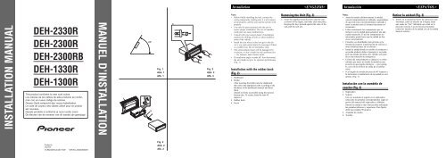
Note:<br />
• Before finally installing the unit, connect the<br />
wiring temporarily, making sure it is all connected<br />
up properly, and the unit and the system work<br />
properly.<br />
• Use only the parts included with the unit to<br />
ensure proper installation. The use of unauthorized<br />
parts can cause malfunctions.<br />
• Consult with your nearest dealer if installation<br />
requires the drilling of holes or other modifications<br />
of the vehicle.<br />
• Install the unit where it does not get in the driver’s<br />
way and cannot injure the passenger if there<br />
is a sudden stop, like an emergency stop.<br />
• The semiconductor laser will be damaged if it<br />
overheats, so don’t install the unit anywhere hot<br />
— for instance, near a heater outlet.<br />
• If installation angle exceeds 60° from horizontal,<br />
the unit might not give its optimum performance.<br />
(Fig. 1)<br />
<strong>Installation</strong> with the rubber bush<br />
(Fig. 2)<br />
1. Dashboard<br />
2. Holder<br />
After inserting the holder into the dashboard,<br />
then select the appropriate tabs according to the<br />
thickness of the dashboard material and bend<br />
them.<br />
(Install as firmly as possible using the top and<br />
bottom tabs. To secure, bend the tabs 90<br />
degrees.)<br />
3. Rubber bush<br />
4. Screw<br />
Removing the Unit (Fig. 3)<br />
5. Insert the supplied extraction keys into the unit,<br />
as shown in the figure, until they click into place.<br />
Keeping the keys pressed against the sides of the<br />
unit, pull the unit out.<br />
Nota:<br />
• Antes de instalar definitivamente la unidad,<br />
conecte temporalmente el cableado, asegurándose<br />
de que todo está convenientemente conectado y<br />
tanto la unidad como el sistema funcionan correctamente.<br />
• Utilice únicamente los componentes que se<br />
incluyen con la unidad para garantizar una adecuada<br />
instalación. El uso de componentes no<br />
autorizados puede hacer que la unidad no funcione<br />
correctamente.<br />
• Consulte a su distribuidor más próximo si la<br />
instalación requiere la perforación de orificios u<br />
otras modificaciones en el vehículo.<br />
• Instale la unidad donde no estorbe al conductor y<br />
no pueda producir daños al pasajero si se produjera<br />
una parada repentina; por ejemplo una parada<br />
en una situación de emergencia.<br />
• El láser del semiconductor se dañará si se sobrecalienta;<br />
por tanto, no instale la unidad en una<br />
posición en que pueda calentarse — (por ejemplo,<br />
cerca de un orificio de salida de la calefacción).<br />
• Si el ángulo de instalación pasa de 60º respecto a<br />
la horizontal, el rendimiento de la unidad no será<br />
óptimo. (Fig. 1)<br />
Instalación con la arandela de<br />
caucho (Fig. 2)<br />
1. Salpicadero<br />
2. Soporte<br />
Una vez insertado el soporte en el salpicadero,<br />
seleccione las pestañas correspondientes según el<br />
grosor del material del salpicadero y dóblelas.<br />
(Instale la unidad lo más firme posible utilizando<br />
las pestañas inferiores y superiores. Para fijarla,<br />
doble las pestañas 90 grados.)<br />
3. Arandela de caucho<br />
4. Tornillo<br />
Retirar la unidad (Fig. 3)<br />
5. Inserte en la unidad las llaves de extracción suministradas,<br />
como se muestra en la figura, hasta<br />
que suene un “clic” indicando que están en la<br />
posición correcta. Con las llaves presionadas<br />
contra los laterales de la unidad, tire de la unidad<br />
hacia el exterior.<br />
Printed in<br />
Imprimé<br />
EW<br />
<br />
Fig. 2<br />
Abb. 2<br />
Afb. 2
Einbau <strong>Installation</strong><br />
<br />
Installazione<br />
<br />
Montage <br />
Hinweis:<br />
• Schließen Sie vor dem Einbau alle Kabel<br />
vorübergehend an und kontrollieren Sie die<br />
Anschlüsse auf Richtigkeit. Überprüfen sind<br />
dann die Funktion des Geräts und Systems.<br />
• Zum Einbau ausschließlich die mitgelieferten<br />
Teile verwenden, um eine korrekte Montage zu<br />
gewährleisten. Die Verwendung von Teilen<br />
anderen Ursprungs kann Störungen zur Folge<br />
haben.<br />
• Falls für den Einbau Löcher zu bohren oder<br />
Änderungen am Fahrzeug vorzunehmen sind,<br />
sollten Sie zuvor Ihren Fachhändler befragen.<br />
• Das Gerät an einer Stelle einbauen, wo es weder<br />
den Fahrer behindert noch den Beifahrer beim<br />
Bremsen verletzen kann.<br />
• Der Halbleiterlaser wird durch Überhitzung<br />
beschädigt. Daher das Gerät keinesfalls an einer<br />
Stelle einbauen, wo es heiß werden kann, wie z.<br />
B. in der Nähe von Heizungsauslässen.<br />
• Falls der Einbauwinkel 60° von der Horizontalen<br />
überschreitet, arbeitet das Gerät unter Umständen<br />
nicht optimal. (Abb. 1)<br />
Einbau mit Gummibuchse<br />
(Abb. 2)<br />
1. Armaturenbrett<br />
2. Einbaukonsole<br />
Nach Einführen der Einbaukonsole in das<br />
Armaturenbrett deren Haltezungen von der Dicke<br />
des Armaturenbretts hineindrücken.<br />
(Die Einbaukonsole mit den oberen und unteren<br />
Zungen sicher befestigen. Zum Sichern die<br />
Haltezunge 90° biegen.)<br />
3. Gummibuchse<br />
4. Schraube<br />
Entnahme des Geräts (Abb. 3)<br />
5. Die beiliegenden Ausziehschlüssel entsprechend<br />
der Abbildung in das Gerät einrasten. Die<br />
Schlüssel gegen die Seiten des Geräts drücken<br />
und das Gerät herausziehen.<br />
Remarque:<br />
• Avant de terminer l’installation de l’appareil,<br />
branchez temporairement les câbles en veillant à<br />
ce que tous les câbles soient correctement connectés<br />
et que l’appareil et la chaîne fonctionnent<br />
parfaitement.<br />
• Utilisez uniquement les pièces fournies avec<br />
l’appareil de manière à en garantir une installation<br />
conforme. L’utilisation de pièces non<br />
autorisées peut provoquer des dysfonctionnements.<br />
• Consultez votre revendeur si l’installation<br />
requiert le perçage de trous ou d’autres modifications<br />
sur le véhicule.<br />
• Installez l’appareil à un endroit où il ne risque<br />
pas de gêner ni de blesser le passager en cas d’arrêt<br />
brutal, par exemple lors d’un freinage en<br />
urgence.<br />
• Le laser à semi-conducteur risque d’être endommagé<br />
en cas de surchauffe; aussi, ne l’installez<br />
pas à des endroits chauds — comme à proximité<br />
d’une bouche de chauffage.<br />
• Si l’angle d’installation dépasse 60° par rapport à<br />
l’horizontale, l’appareil risque de ne pas fournir<br />
de performances optimales. (Fig. 1)<br />
<strong>Installation</strong> avec le manchon en<br />
caoutchouc (Fig. 2)<br />
1. Tableau de bord<br />
2. Support<br />
Après avoir introduit le support dans le tableau<br />
de bord, sélectionnez les pattes appropriées en<br />
fonction de l’ép<strong>ais</strong>seur du matériau du tableau de<br />
bord et repliez-les.<br />
(Installez-le aussi fermement que possible à<br />
l’aide des pattes supérieure et inférieure. Pour le<br />
fixer en position, repliez les pattes de 90 degrés.)<br />
3. Manchon en caoutchouc<br />
4. Vis<br />
Retrait de l’appareil (Fig. 3)<br />
5. Insérez les clés d’extraction fournies dans l’appareil<br />
comme illustré dans la figure jusqu’à ce<br />
qu’elles s’encliquettent. Tout en maintenant les<br />
clés contre les sections latérales de l’appareil,<br />
extrayez celui-ci.<br />
Nota:<br />
• Prima di installare l’apparecchio in modo definitivo,<br />
collegare i cavi in modo provvisorio, per<br />
accertare che tutto sia collegato correttamente, e<br />
che l’apparecchio e il sistema funzionino perfettamente.<br />
• Per garantire un’installazione corretta, usare solo<br />
le parti fornite insieme all’apparecchio.<br />
L’impiego di parti non approvate può causare<br />
difetti di funzionamento.<br />
• Rivolgersi al rivenditore più vicino per informazioni,<br />
se l’installazione richiede l’esecuzione<br />
di fori o altre modifiche alla vettura.<br />
• Installare l’apparecchio in una posizione in cui<br />
non intralci il conducente e non possa causare<br />
danni al passeggero in caso di arresto improvviso,<br />
come un arresto d’emergenza.<br />
• Il laser a semiconduttore può essere danneggiato<br />
dal surriscaldamento, quindi non installare l’apparecchio<br />
in punti molto caldi — per esempio in<br />
vicinanza di una bocchetta di riscaldamento.<br />
• Se l’angolo di installazione supera 60º dall’orizzontale,<br />
è possibile che l’apparecchio non fornisca<br />
le migliori prestazioni. (Fig. 1)<br />
Installazione con boccola di<br />
gomma (Fig. 2)<br />
1. Plancia<br />
2. Supporto<br />
Dopo aver inserito il supporto nella plancia,<br />
scegliere le linguette appropriate in base allo<br />
spessore della plancia e piegarle.<br />
(Installare saldamente servendosi delle linguette<br />
superiori ed inferiori. Per fissare, piegare le<br />
linguette a 90 gradi.)<br />
3. Boccola di gomma<br />
4. Vite<br />
Rimozione dell’apparecchio (Fig. 3)<br />
5. Inserire nell’apparecchio i dispositivi di<br />
estrazione in dotazione, come mostrato in figura,<br />
fino a quando s’innestano in posizione. Estrarre<br />
l’apparecchio tenendo premuti i dispositivi contro<br />
i lati e tirando.z<br />
Opmerking:<br />
• Sluit de draden tijdelijk aan en controleer of alles<br />
goed is aangesloten en het toestel en het systeem<br />
correct werken alvorens het toestel definitief te<br />
monteren.<br />
• Gebruik met het oog op een degelijke montage<br />
alleen de bij dit toestel geleverde onderdelen. Het<br />
gebruik van niet-goedgekeurde onderdelen kan<br />
defecten veroorzaken.<br />
• Neem contact op met uw dichtstbijzijnde handelaar<br />
als voor de montage gaten moeten worden<br />
geboord of andere wijzigingen aan het voertuig<br />
nodig zijn.<br />
• Monteer het toestel op een plaats waar het de<br />
bestuurder niet kan hinderen en geen passagiers<br />
kan verwonden bij een bruuske stopbeweging,<br />
bijvoorbeeld in een noodgeval.<br />
• Aangezien de halfgeleiderlaser zal worden<br />
beschadigd in geval van oververhitting, mag u<br />
het toestel niet monteren in de buurt van een<br />
warmtebron,—bijvoorbeeld dicht bij een verwarmingsuitlaat.<br />
• Als het toestel wordt gemonteerd in een hoek van<br />
meer dan 60º ten opzichte van de horizontale<br />
positie, zal het toestel mogelijk niet optimaal<br />
werken. (Afb. 1)<br />
Montage met behulp van de rubberbus(Afb.<br />
2)<br />
1. Dashboard<br />
2. Houder<br />
Plaats de houder in het dashboard en kies vervolgens<br />
de geschikte lipjes, overeenkomstig de dikte<br />
van het dashboardmateriaal, en buig ze.<br />
(Monteer zo stevig mogelijk met de bovenste en<br />
onderste lipjes. Om de lipjes vast te zetten, buigt<br />
u ze 90 graden.)<br />
3. Rubberbus<br />
4. Schroef<br />
Verwijderen van het toestel (Afb. 3)<br />
5. Steek de meegeleverde uittreksleutels in het toestel,<br />
zoals getoond op de afbeelding, tot ze vastklikken.<br />
Houd de sleutels tegen de zijkanten van<br />
het toestel gedrukt en trek het toestel naar buiten.
Connecting the Units<br />
<br />
5.<br />
Note:<br />
Depending on the kind of vehicle, the functio<br />
of 3* and 5* may be different. In this case, be<br />
sure to connect 2* to 5* and 4* to 3*.<br />
3*<br />
5*<br />
1*<br />
2*<br />
4*<br />
7. Cap (1*)<br />
When not using this terminal,<br />
do not remove the cap.<br />
8. Yellow (3*)<br />
Back-up<br />
(or accessory)<br />
10. Red (5*)<br />
Accessory<br />
(or back-up)<br />
12. Black (ground)<br />
To vehicle (metal) body.<br />
13.ISO connector<br />
Note:<br />
In some vehicles, the ISO connector may be<br />
divided into two. In this case, be sure to<br />
connect to both connectors.<br />
2. Rear output<br />
6. Connect leads of the<br />
same color to each other.<br />
9. Yellow (2*)<br />
To terminal always supplied<br />
with power regardless of<br />
ignition switch position.<br />
11. Red (4*)<br />
To electric terminal controlled<br />
by ignition switch (12 V DC)<br />
ON/OFF.<br />
1. This product<br />
3. Antenna jack<br />
14.Speaker leads<br />
White : Front left +<br />
White/black : Front left ≠<br />
Gray : Front right +<br />
Gray/black : Front right ≠<br />
Green : Rear left +<br />
Green/black : Rear left ≠<br />
Violet : Rear right +<br />
Violet/black : Rear right ≠<br />
4. Fuse<br />
23. Blue/white (6*)<br />
25.<br />
18. Blue/white<br />
To system control terminal of the power amp<br />
(max. 300 mA 12 V DC).<br />
24. Blue/white (7*)<br />
To Auto-antenna relay control<br />
terminal (max. 300 mA 12 V DC).<br />
15. Connecting cords with<br />
RCA pin plugs (sold separately).<br />
17. Yellow/black<br />
If you use a cellular telephone, connect it via the Audio<br />
Mute lead on the cellular telephone. If not, keep the Audio<br />
Mute lead free of any connections.<br />
The pin position of the ISO connector will differ<br />
depends on the type of vehicle. Connect 6* and 7*<br />
when Pin 5 is an antenna control type. In another<br />
type of vehicle, never connect 6* and 7*.<br />
20.Rear speaker (Left)<br />
+<br />
≠<br />
19. System remote control<br />
16. Power amp<br />
(sold separately)<br />
21.Rear speaker (Right)<br />
22. Perform these connections when using<br />
a different amp (sold separately).<br />
+<br />
≠<br />
Fig. 4<br />
Abb. 4<br />
Afb. 4<br />
Note:<br />
• This unit is for vehicles with a 12-volt battery<br />
and negative grounding. Before installing it in a<br />
recreational vehicle, truck, or bus, check the battery<br />
voltage.<br />
• To avoid shorts in the electrical system, be sure<br />
to disconnect the ≠ battery cable before beginning<br />
installation.<br />
• Refer to the owner’s <strong>manual</strong> for details on connecting<br />
the power amp and other units, then<br />
make connections correctly.<br />
• Secure the wiring with cable clamps or adhesive<br />
tape. To protect the wiring, wrap adhesive tape<br />
around them where they lie against metal parts.<br />
• Route and secure all wiring so it cannot touch<br />
any moving parts, such as the gear shift, handbrake<br />
and seat rails. Do not route wiring in<br />
places that get hot, such as near the heater outlet.<br />
If the insulation of the wiring melts or gets torn,<br />
there is a danger of the wiring short-circuiting to<br />
the vehicle body.<br />
• Don’t pass the yellow lead through a hole into<br />
the engine compartment to connect to the battery.<br />
This will damage the lead insulation and cause a<br />
very dangerous short.<br />
• Do not shorten any leads. If you do, the protection<br />
circuit may fail to work when it should.<br />
• Never feed power to other equipment by cutting<br />
the insulation of the power supply lead of the<br />
unit and tapping into the lead. The current capacity<br />
of the lead will be exceeded, causing overheating.<br />
• When replacing fuse, be sure to use only fuse of<br />
the rating prescribed on this unit.<br />
• Since a unique BPTL circuit is employed, never<br />
wire so the speaker leads are directly grounded<br />
or the left and right ≠ speaker leads are common.<br />
• Speakers connected to this unit must be highpower<br />
types with minimum rating of 45 W (50<br />
W)* and impedance of 4 to 8 ohms. Connecting<br />
speakers with output and/or impedance values<br />
other than those noted here may result in the<br />
speakers catching fire, emitting smoke, or<br />
becoming damaged.<br />
*<strong>DEH</strong>-2330R, <strong>DEH</strong>-2300R and <strong>DEH</strong>-2300RB<br />
• When this product’s source is switched ON, a<br />
control signal is output through the blue/white<br />
lead. Connect to an external power amp’s system<br />
remote control or the car’s Auto-antenna relay<br />
control terminal (max. 300 mA 12 V DC). If the<br />
car features a glass antenna, connect to the antenna<br />
booster power supply terminal.<br />
• When an external power amp is being used with<br />
this system, be sure not to connect the blue/white<br />
lead to the amp’s power terminal. Likewise, do<br />
not connect the blue/white lead to the power terminal<br />
of the auto-antenna. Such connection could<br />
cause excessive current drain and malfunction.<br />
• To avoid short-circuiting, cover the disconnected<br />
lead with insulating tape. Especially, insulate the<br />
unused speaker leads without fail. There is a possibility<br />
of short-circuiting if the leads are not<br />
insulated.<br />
• If this unit is installed in a vehicle that does not<br />
have an ACC (accessory) position on the ignition<br />
switch, the red lead of the unit should be connected<br />
to a terminal coupled with ignition switch<br />
ON/OFF operations. If this is not done, the vehicle<br />
battery may be drained when you are away<br />
from the vehicle for several hours.<br />
OFF<br />
ACC<br />
ON<br />
START<br />
ACC position<br />
• The black lead is ground. Please ground this lead<br />
separately from the ground of high-current products<br />
such as power amps.<br />
If you ground the products together and the<br />
ground becomes detached, there is a risk of damage<br />
to the products or fire.<br />
• Cords for this product and those for other products<br />
may be different colors even if they have the<br />
same function. When connecting this product to<br />
another product, refer to the supplied <strong>Installation</strong><br />
<strong>manual</strong>s of both products and connect cords that<br />
have the same function.<br />
OFF<br />
ON<br />
START<br />
No ACC position<br />
Connection Diagram (Fig. 4)<br />
1. This product<br />
2. Rear output<br />
3. Antenna jack<br />
4. Fuse<br />
5. Note:<br />
Depending on the kind of vehicle, the function of<br />
3* and 5* may be different. In this case, be sure<br />
to connect 2* to 5* and 4* to 3*.<br />
6. Connect leads of the same color to each other.<br />
7. Cap (1*)<br />
When not using this terminal, do not remove the<br />
cap.<br />
8. Yellow (3*)<br />
Back-up (or accessory)<br />
9. Yellow (2*)<br />
To terminal always supplied with power regardless<br />
of ignition switch position.<br />
10. Red (5*)<br />
Accessory (or back-up)<br />
11. Red (4*)<br />
To electric terminal controlled by ignition switch<br />
(12 V DC) ON/OFF.<br />
12. Black (ground)<br />
To vehicle (metal) body.<br />
13. ISO connector<br />
Note:<br />
In some vehicles, the ISO connector may be<br />
divided into two. In this case, be sure to connect<br />
to both connectors.<br />
14. Speaker leads<br />
White: Front left +<br />
White/black: Front left ≠<br />
Gray: Front right +<br />
Gray/black: Front right ≠<br />
Green: Rear left +<br />
Green/black: Rear left ≠<br />
Violet: Rear right +<br />
Violet/black: Rear right ≠<br />
15. Connecting cords with RCA pin plugs (sold separately).<br />
16. Power amp (sold separately)<br />
17. Yellow/black<br />
If you use a cellular telephone, connect it via the<br />
Audio Mute lead on the cellular telephone. If not,<br />
keep the Audio Mute lead free of any connections.<br />
18. Blue/white<br />
To system control terminal of the power amp<br />
(max. 300 mA 12 V DC).<br />
19. System remote control<br />
20. Rear speaker (Left)<br />
21. Rear speaker (Right)<br />
22. Perform these connections when using a different<br />
amp (sold separately).<br />
23. Blue/white (6*)<br />
24. Blue/white (7*)<br />
To Auto-antenna relay control terminal (max.<br />
300 mA 12 V DC).<br />
25. The pin position of the ISO connector will differ<br />
depends on the type of vehicle. Connect 6* and 7*<br />
when Pin 5 is an antenna control type. In another<br />
type of vehicle, never connect 6* and 7*.
Conexión de las unidades<br />
<br />
5.<br />
Note:<br />
Depending on the kind of vehicle, the functio<br />
of 3* and 5* may be different. In this case, be<br />
sure to connect 2* to 5* and 4* to 3*.<br />
3*<br />
5*<br />
1*<br />
2*<br />
4*<br />
7. Cap (1*)<br />
When not using this terminal,<br />
do not remove the cap.<br />
8. Yellow (3*)<br />
Back-up<br />
(or accessory)<br />
10. Red (5*)<br />
Accessory<br />
(or back-up)<br />
12. Black (ground)<br />
To vehicle (metal) body.<br />
13.ISO connector<br />
Note:<br />
In some vehicles, the ISO connector may be<br />
divided into two. In this case, be sure to<br />
connect to both connectors.<br />
2. Rear output<br />
6. Connect leads of the<br />
same color to each other.<br />
9. Yellow (2*)<br />
To terminal always supplied<br />
with power regardless of<br />
ignition switch position.<br />
11. Red (4*)<br />
To electric terminal controlled<br />
by ignition switch (12 V DC)<br />
ON/OFF.<br />
1. This product<br />
3. Antenna jack<br />
14.Speaker leads<br />
White : Front left +<br />
White/black : Front left ≠<br />
Gray : Front right +<br />
Gray/black : Front right ≠<br />
Green : Rear left +<br />
Green/black : Rear left ≠<br />
Violet : Rear right +<br />
Violet/black : Rear right ≠<br />
4. Fuse<br />
23. Blue/white (6*)<br />
25.<br />
18. Blue/white<br />
To system control terminal of the power amp<br />
(max. 300 mA 12 V DC).<br />
24. Blue/white (7*)<br />
To Auto-antenna relay control<br />
terminal (max. 300 mA 12 V DC).<br />
15. Connecting cords with<br />
RCA pin plugs (sold separately).<br />
17. Yellow/black<br />
If you use a cellular telephone, connect it via the Audio<br />
Mute lead on the cellular telephone. If not, keep the Audio<br />
Mute lead free of any connections.<br />
The pin position of the ISO connector will differ<br />
depends on the type of vehicle. Connect 6* and 7*<br />
when Pin 5 is an antenna control type. In another<br />
type of vehicle, never connect 6* and 7*.<br />
20.Rear speaker (Left)<br />
+<br />
≠<br />
19. System remote control<br />
16. Power amp<br />
(sold separately)<br />
21.Rear speaker (Right)<br />
22. Perform these connections when using<br />
a different amp (sold separately).<br />
+<br />
≠<br />
Fig. 4<br />
Abb. 4<br />
Afb. 4<br />
Nota:<br />
• Esta unidad está diseñada para vehículos con una<br />
batería de 12 voltios y toma de tierra negativa.<br />
Antes de instalarla en un vehículo recreativo, un<br />
camión o un autobús, compruebe el voltaje.<br />
• Para evitar cortocircuitos, asegúrese de que<br />
desconecta el ≠ cable de la batería antes de<br />
comenzar la instalación.<br />
• Consulte el <strong>manual</strong> del usuario si desea información<br />
adicional sobre el procedimiento para<br />
conectar el amplificador de potencia y las demás<br />
unidades; a continuación, haga correctamente las<br />
conexiones.<br />
• Fije el cableado con mordazas para cable o cinta<br />
adhesiva. Para proteger el cableado, forre con<br />
cinta adhesiva los cables donde rocen con componentes<br />
metálicos.<br />
• Dirija y fije todo el cableado de modo que no<br />
roce con ningún componente móvil (por ejemplo,<br />
la palanca de cambios, el freno de mano o los<br />
carriles de deslizamiento del asiento). No lleve el<br />
cableado por posiciones que se calienten (por<br />
ejemplo cerca de un orificio de salida de la calefacción).<br />
Si el <strong>ais</strong>lamiento del cableado se funde<br />
o se rasga, podría provocar un cortocircuito en la<br />
carrocería del vehículo.<br />
• No pase el cable amarillo a través de un orificio<br />
en el compartimento del motor para conectarlo a<br />
la batería. Podría dañarse el <strong>ais</strong>lamiento del cable<br />
y provocar un cortocircuito muy peligroso.<br />
• No acorte ningún cable. Si lo hace, el circuito de<br />
protección podría dejar de funcionar en el<br />
momento necesario.<br />
• No facilite alimentación a otro equipo cortando<br />
el <strong>ais</strong>lamiento del cable de la fuente de alimentación<br />
de la unidad y empalmando el cable.<br />
La capacidad de corriente del cable podría<br />
sobrepasarse, produciendo calentamiento.<br />
• Cuando sustituya un fusible, asegúrese de que<br />
utiliza únicamente un fusible con el amperaje<br />
prescrito en esta unidad.<br />
• Como se emplea un único circuito BPTL, no<br />
instale nunca el cableado de modo que los cables<br />
de los altavoces estén conectados directamente a<br />
tierra o que los cables de los altavoces derecho e<br />
izquierdo ≠ sean comunes.<br />
• Los altavoces conectados a esta unidad deben ser<br />
de alta potencia, como mínimo de 45 W (50 W)*,<br />
y una impedancia de 4 a 8 ohmios.<br />
Si se conectan altavoces con otros valores de<br />
potencia de salida y/o impedancia que los prescritos<br />
en este <strong>manual</strong>, puede que se quemen,<br />
emitan humo o se dañen.<br />
*<strong>DEH</strong>-2330R, <strong>DEH</strong>-2300R y <strong>DEH</strong>-2300RB<br />
• Si la fuente de este producto está encendida<br />
(ON), se emitirá una señal de control a través del<br />
cable azul/blanco. Conéctelo al terminal de control<br />
remoto del amplificador de potencia externo<br />
o al terminal de control de relé de la antena del<br />
automóvil (máx. 300 mA 12 V CC). Si el<br />
automóvil tiene una antena de fibra de vidrio,<br />
conéctela al terminal de la fuente de alimentación<br />
del amplificador de la antena.<br />
• Si utiliza un amplificador de potencia externo<br />
con este sistema, asegúrese de no conectar el<br />
cable azul/blanco al terminal de alimentación del<br />
amplificador. De igual modo, no conecte el cable<br />
azul/blanco al terminal de alimentación de la<br />
antena del automóvil. Esta conexión podría<br />
provocar un consumo excesivo de corriente y<br />
funcionar mal.<br />
• Para evitar cortocircuitos, cubra el cable pelado<br />
con cinta <strong>ais</strong>lante. Especialmente, no deje de <strong>ais</strong>lar<br />
los cables de los altavoces que no se utilicen.<br />
Si los cables no están <strong>ais</strong>lados, puede producirse<br />
un cortocircuito.<br />
• Si esta unidad se instala en un vehículo que no<br />
tenga una posición ACC (accesorio) en el interruptor<br />
de encendido, el cable rojo de la unidad debe<br />
conectarse a un terminal que esté asociado con el<br />
interruptor de encendido (ON/OFF). Si no se hace<br />
así, la batería del vehículo podría descargarse si<br />
permanece varias horas fuera del vehículo.<br />
OFF<br />
ACC<br />
ON<br />
START<br />
Posición ACC<br />
Sin posición ACC<br />
• El cable negro es la toma de tierra. Conecte a<br />
tierra este cable por separado; es decir, a otra<br />
toma de tierra que no sea la de los productos de<br />
alta corriente (por ejemplo los amplificadores de<br />
potencia).<br />
Si los productos se conectaran juntos a tierra y<br />
esa toma de tierra se soltara, existiría el riesgo de<br />
que se dañaran o incluso que se incendiaran.<br />
• Los cables para esta unidad y aquéllas para las<br />
unidades pueden ser de colores diferentes aun si<br />
tienen la misma función. Cuando se conecta esta<br />
unidad a otra, refiérase a los <strong>manual</strong>es de instalación<br />
de ambas unidades y conecte los cables<br />
que tienen la misma función.<br />
OFF<br />
ON<br />
START<br />
Diagrama de conexión (Fig. 4)<br />
1. Esta unidad<br />
2. Salida posterior<br />
3. Toma de antena<br />
4. Fusible<br />
5. Nota:<br />
Según el tipo de vehículo, la función de 3* y 5*<br />
puede ser diferente. En este caso, asegúrese de<br />
conectar el 2* al 5* y el 4* al 3*.<br />
6. Conecte entre sí los cables del mismo color.<br />
7. Cubierta (1*)<br />
Cuando no utilice este terminal, no quite la<br />
cubierta.<br />
8. Amarillo (3*)<br />
Reserva (o accesorio)<br />
9. Amarillo (2*)<br />
Al terminal que se encuentra siempre bajo tensión,<br />
independientemente de la posición del interruptor<br />
de encendido.<br />
10. Rojo (5*)<br />
Accesorio (o de reserva)<br />
11. Rojo (4*)<br />
Al terminal eléctrico controlado por el interruptor<br />
de encendido (12 V CC) ON/OFF.<br />
12. Negro (tierra)<br />
A la carrocería (metal) del vehículo.<br />
13. Conector ISO<br />
Nota:<br />
En algunos vehículos, el conector ISO puede<br />
estar dividido en dos. En este caso, asegúrese de<br />
conectar ambos conectores.<br />
14. Cables de los altavoces<br />
Blanco: Anterior izquierdo +<br />
Blanco/negro: Anterior izquierdo ≠<br />
Gris: Anterior derecho +<br />
Gris/negro: Anterior derecho ≠<br />
Verde: Posterior izquierdo +<br />
Verde/negro: Posterior izquierdo ≠<br />
Violeta: Posterior derecho +<br />
Violeta/negro: Posterior derecho ≠<br />
15. Conexión de cables con enchufes de patillas<br />
RCA (vendidos por separado).<br />
16. Amplificador de potencia (vendido por separado)<br />
17. Amarillo/negro<br />
Si utiliza un teléfono móvil, conéctelo a través<br />
del cable Audio Mute del teléfono móvil. En caso<br />
contrario, no conecte el cable Audio Mute a<br />
ningún terminal.<br />
18. Azul/blanco<br />
Al terminal de control del sistema del amplificador<br />
de potencia (máx. 300 mA 12 V CC).<br />
19. Control remoto del sistema<br />
20. Altavoz posterior (Izquierdo)<br />
21. Altavoz posterior (Derecho)<br />
22. Haga estas conexiones cuando utilice otro amplificador<br />
(vendido por separado).<br />
23. Azul/blanco (6*)<br />
24. Azul/blanco (7*)<br />
Al terminal de control de relé de la antena del<br />
automóvil (máx. 300 mA 12 V CC).<br />
25. La posición de las patillas del conector ISO puede<br />
ser diferente según el tipo de vehículo. Conecte 6*<br />
y 7* si la Patilla 5 es de tipo control de antena. En<br />
otro tipo de vehículo, no conecte nunca 6* y 7*.
Anschließen der Geräte<br />
<br />
Raccordement des appareils<br />
<br />
Hinweis:<br />
• Dieses Gerät ist auf Fahrzeuge mit 12-V-Batterie<br />
und negativer Erdung (Minuspol an Masse) ausgelegt.<br />
Vor dem Einbau in Wohnmobile, LKWs<br />
oder Busse die Batteriespannung prüfen.<br />
• Unbedingt das Massekabel ≠ der Batterie vor<br />
der Montage abklemmen, um Kurzschlüsse im<br />
elektrischen System auszuschließen.<br />
• Lesen Sie die Einzelheiten zum Anschluss des<br />
Leistungsverstärkers und anderer Komponenten<br />
in der Bedienungsanleitung bevor Sie die<br />
Anschlüsse vornehmen, um Fehler zu vermeiden.<br />
• Die Kabel mit Kabelklemmen oder Klebeband<br />
sichern. Zum Schutz der Kabel sollten Sie sie an<br />
den Stellen, an denen Sie Metallteile berühren<br />
mit Klebeband umwickeln.<br />
• Verlegen und befestigen Sie alle Kabel so, dass<br />
sie keine beweglichen Teile wie Schalthebel,<br />
Handbremshebel und Sitzschienen berühren. Die<br />
Kabel dürfen nicht an heiß werdenden Bereichen<br />
wie z. B. Heizungsauslässe entlanggeführt werden.<br />
Falls die Isolierung von Kabeln schmilzt<br />
oder durchgescheuert wird, besteht Gefahr von<br />
Kurzschlüssen mit der Karosserie.<br />
• Das gelbe Kabel zum Anschluss an die Batterie<br />
keinesfalls durch ein Loch in den Motorraum<br />
führen. Dadurch würde die Isolierung beschädigt,<br />
was einen gefährlichen Kurzschluss zur Folge hat.<br />
• Verkürzen Sie niemals Kabel. Dadurch könnte<br />
die Schutzschaltung nicht ansprechen, wenn es<br />
erforderlich ist.<br />
• Niemals zur Stromversorgung anderer Geräte die<br />
Isolierung am Stromversorgungskabel des Geräts<br />
abschneiden und davon Strom abzapfen. Dadurch<br />
wird die Strombelastbarkeit des Kabels überschritten,<br />
was Überhitzung zur Folge hat.<br />
• Als Ersatzsicherung dürfen nur solche mit dem<br />
vorgeschriebenen Nennwert verwendet werden.<br />
• Aufgrund des speziellen BPTL-Schaltkreises dürfen<br />
Lautsprecherkabel niemals direkt geerdet<br />
oder die Minuskabel ≠ von linkem und rechtem<br />
Kanal verbunden werden.<br />
• Die Lautsprecher, die an dieses Gerät<br />
angeschlossen werden, müssen auf eine<br />
Mindestnennleistung von 45 W (50 W)* und eine<br />
Impedanz von 4 bis 8 Ohm ausgelegt sein.<br />
Falls Lautsprecher mit anderen Leistungsund/oder<br />
Impedanzwerten angeschlossen werden,<br />
können die Lautsprecher in Brand geraten, Rauch<br />
entwickeln oder beschädigt werden.<br />
*<strong>DEH</strong>-2330R, <strong>DEH</strong>-2300R und <strong>DEH</strong>-2300RB<br />
• Beim Einschalten einer Programmquelle in<br />
diesem Gerät wird ein Steuersignal über das<br />
blau/weiße Kabel ausgegeben. Verbinden Sie es<br />
mit dem Fernsteuerungseingang eines<br />
Leistungsverstärkers oder mit dem<br />
Antennenheber-Steueranschluss (max. 300 mA,<br />
12 V Gleichspannung) des Fahrzeugs. Falls das<br />
Fahrzeug mit einer Scheibenantenne ausgestattet<br />
ist, das Kabel mit dem Antennenverstärker-<br />
Stromversorgungsanschluss verbinden.<br />
• Falls ein separater Leistungsverstärker im System<br />
verwendet wird, sollten Sie darauf achten, dass<br />
Sie das blau/weiße Kabel nicht versehentlich an<br />
der Stromversorgungsbuchse des Verstärkers<br />
anschließen. Gleichermaßen darf das blau/weiße<br />
Kabel nicht mit dem Stromversorgungsanschluss<br />
des Antennenhebers angeschlossen werden.<br />
Solche Fehler können eine übermäßige<br />
Stromentnahme und Störungen verursachen.<br />
• Zur Vermeidung von Kurzschlüssen gelöste<br />
Kabel mit Isolierband umwickeln. Unbedingt<br />
unbenutzte Lautsprecherkabel isolieren. Falls die<br />
Kabel nicht isoliert werden, besteht Gefahr von<br />
Kurzschlüssen.<br />
• Falls das Gerät in ein Fahrzeug eingebaut wird,<br />
dessen Zündschalter keine ACC-Position<br />
(Nebenverbraucher) besitzt, sollten Sie das rote<br />
Kabel des Geräts an eine andere Klemme<br />
anschließen, die mit dem Ein-/Ausschalten der<br />
Zündung gekoppelt ist. Anderenfalls kann sich<br />
die Batterie bei abgestelltem Motor innerhalb<br />
weniger Stunden entladen.<br />
OFF<br />
ACC<br />
ON<br />
START<br />
ACC-Position<br />
• Das schwarze Kabel ist das Erdungskabel. Dieses<br />
Kabel ist getrennt vom Masseanschluss von<br />
Hochstromgeräten wie Leistungsverstärkern zu erden.<br />
Falls die Geräte gemeinsam geerdet werden und sich<br />
der Masseanschluss lösen sollte, können Schäden an<br />
den Geräten und sogar Brand resultieren.<br />
• Kabel dieses Geräts und die anderer Geräte können<br />
unterschiedliche Farben haben, auch wenn<br />
sie die gleichen Funktionen haben. Beim<br />
Anschluß dieses Geräts an ein anderes Gerät<br />
unter Bezugnahme auf die mit beiden Geräten<br />
mitgelieferten <strong>Installation</strong>sanleitungen die Kabel<br />
mit derselben Funktion verbinden.<br />
OFF<br />
ON<br />
START<br />
Ohne ACC-Position<br />
Anschlussplan (Abb. 4)<br />
1. Dieses Gerät<br />
2. Ausgang für Hecklautsprecher<br />
3. Antennenbuchse<br />
4. Sicherung<br />
5. Hinweis:<br />
Je nach Fahrzeug können 3* und 5* unterschiedliche<br />
Funktionen aufweisen. In diesem Fall<br />
2* mit 5* und 4* mit 3* verbinden.<br />
6. Kabel gleicher Farbe miteinander verbinden.<br />
7. Kappe (1*)<br />
Diese Kappe nicht entfernen, falls der Anschluss<br />
nicht beschaltet wird.<br />
8. Gelb (3*)<br />
Reserve (oder Zubehör)<br />
9. Gelb (2*)<br />
An eine Klemme anschließen, an der ungeachtet<br />
der Zündschalterstellung stets Strom anliegt.<br />
10. Rot (5*)<br />
Zubehör (oder Reserve)<br />
11. Rot (4*)<br />
An eine Zündschalterklemme (12 V<br />
Gleichspannung) anschließen, die mit dem Ein-<br />
/Ausschalten der Zündung gekoppelt ist.<br />
12. Schwarz (Masse)<br />
An Karosserie (Metallteil)<br />
13. ISO-Auschluß<br />
Hinweis:<br />
Bei manchen Fahrzeugen kann der ISO-Auschluß<br />
in zwei Stecker aufgeteilt sein. In diesem Fall<br />
unbedingt beide Stecker anschließen.<br />
14. Lautsprecherkabel<br />
Weiß: Vorn links +<br />
Weiß/schwarz: Vorn links ≠<br />
Grau: Vorn rechts +<br />
Grau/schwarz: Vorn rechts ≠<br />
Grün: Hinten links +<br />
Grün/schwarz: Hinten links ≠<br />
Violett: Hinten rechts +<br />
Violett/schwarz: Hinten rechts ≠<br />
15. Mit RCA-Stiftsteckerkabeln verbinden (getrennt<br />
erhältlich).<br />
16. Leistungsverstärker (getrennt erhältlich)<br />
17. Gelb/schwarz<br />
Bei Fahrzeugen mit Funktelefon oder<br />
Freisprechanlage mit deren<br />
Stummschaltungsanschluss oder -kabel (AUDIO<br />
MUTE) verbinden. Falls kein Funktelefon etc.<br />
installiert ist, das Stummschaltungskabel nirgendwo<br />
anschließen.<br />
18. Blau/weiß<br />
An Systemsteuerungsanschluss des<br />
Leistungsverstärkers (max. 300 mA, 12 V<br />
Gleichspannung).<br />
19. Systemfernsteuerung<br />
20. Hecklautsprecher (links)<br />
21. Hecklautsprecher (rechts)<br />
22. Diese Anschlüsse bei Verwendung eines separaten<br />
Verstärkers (getrennt erhältlich) ausführen.<br />
23. Blau/weiß (6*)<br />
24. Blau/weiß (7*)<br />
An Antennenheberrel<strong>ais</strong>-Steueranschluss (max.<br />
300 mA, 12 V Gleichspannung).<br />
25. Die Kontaktstiftbelegung von ISO-Auschluß vom<br />
Fahrzeugtyp ab. Falls Kontaktstift 5 zur<br />
Antennenhebersteuerung dient, 6* und 7*<br />
anschließen. Bei anderen Fahrzeugen 6* und 7*<br />
niemals anschließen.<br />
Remarque:<br />
• Cet appareil est conçu pour les véhicules équipés<br />
d’une batterie de 12 volts et d’une masse négative.<br />
Avant de l’installer dans un véhicule de loisirs, un<br />
camion ou un bus, vérifiez la tension de la batterie.<br />
• Pour éviter les courts-circuits dans le système<br />
électrique, débranchez le fil de la batterie ≠<br />
avant d’entamer l’installation.<br />
• Reportez-vous au mode d’emploi pour plus de<br />
détails sur le raccordement à l’amplificateur de<br />
puissance et à d’autres appareils, puis établissez<br />
les connexions correctement.<br />
• Fixez les fils à l’aide de serre-fil ou de bande<br />
adhésive. Pour protéger les fils, enroulez-les de<br />
bande adhésive aux endroits où ils sont en contact<br />
avec des pièces métalliques.<br />
• Cheminez et fixez tous les fil de façon à ce qu’ils<br />
n’entrent pas en contact avec des pièces mobiles,<br />
comme le levier du changement de vitesses, le<br />
frein à main ou les rails des sièges. Ne cheminez<br />
pas les fils à des endroits chauds comme à proximité<br />
des bouches de chauffage. Si la gaine<br />
isolante des fils fond ou se déchire, les fils<br />
risquent d’être en court-circuit avec la carrosserie<br />
du véhicule.<br />
• Ne faites pas passer le fil jaune par un orifice dans<br />
le compartiment moteur pour le raccorder à la batterie.<br />
Cela risque d’endommager la gaine isolante du<br />
fil et de provoquer un court-circuit très dangereux.<br />
• Ne mettez aucun fil en court-circuit. Sinon, le<br />
circuit de protection risque de ne pas fonctionner<br />
lorsqu’il le devrait.<br />
• N’alimentez en aucun cas un autre équipement<br />
en découpant la gaine isolante du fil d’alimentation<br />
et en puisant du courant sur le fil. La capacité<br />
de courant du fil risque d’être dépassée,<br />
provoquant ainsi une surchauffe.<br />
• Lors du remplacement du fusible, utilisez uniquement<br />
un fusible de l’intensité prescrite sur cet<br />
appareil.<br />
• Etant donné qu’un seul circuit BPTL est utilisé,<br />
n’établissez jam<strong>ais</strong> le câblage de façon à mettre<br />
directement les fils des haut-parleurs à la masse<br />
et n’utilisez pas de fil commun pour les haut-parleurs<br />
gauche et droit ≠.<br />
• Les haut-parleurs raccordés à cet appareil doivent<br />
être de type à grande puissance avec une puissance<br />
nominale minimale de 45 W (50 W)* et<br />
une impédance de 4 à 8 ohms.<br />
Le raccordement de haut-parleurs offrant une<br />
puissance de sortie et une impédance différentes<br />
des valeurs prescrites peut entraîner un début<br />
d’incendie, des émissions de fumée ou des dommages<br />
aux haut-parleurs.<br />
*<strong>DEH</strong>-2330R, <strong>DEH</strong>-2300R et <strong>DEH</strong>2300RB<br />
• Lorsque cet appareil source est commuté sur ON, un<br />
signal de commande est transmis via le fil bleu/blanc.<br />
Raccordez-le à la télécommande d’un système d’amplification<br />
de puissance externe ou à la prise de commande<br />
du rel<strong>ais</strong> de l’antenne de la voiture (max. 300<br />
mA 12 V DC). Si la voiture est équipée d’une<br />
antenne intégrée dans une vitre, raccordez-le à la<br />
prise d’alimentation de l’amplificateur d’antenne.<br />
• Si vous utilisez un amplificateur externe avec cet<br />
appareil, ne raccordez pas le fil bleu/blanc à la<br />
prise d’alimentation de l’amplificateur. De même,<br />
ne raccordez pas le fil bleu/blanc à la prise d’alimentation<br />
de l’antenne automatique. Une telle<br />
connexion peut entraîner une consommation de<br />
courant excessive et un dysfonctionnement.<br />
• Pour éviter les courts-circuits, recouvrez le fil<br />
déconnecté de bande isolante. En particulier,<br />
isolez correctement les fils de haut-parleur inutilisés.<br />
Il y a un risque de court-circuit si les fils ne<br />
sont pas isolés.<br />
• Si cet appareil est installé dans un véhicule dont<br />
le contact n’est pas doté d’une position ACC<br />
(accessoires), le fil rouge de l’appareil doit être<br />
branché sur une prise couplée avec la commutation<br />
marche/arrêt (ON/OFF) du contact. Si ce<br />
n’est pas fait, la batterie du véhicule risque de<br />
s’épuiser si vous quittez le véhicule pendant<br />
quelques heures.<br />
OFF<br />
ACC<br />
ON<br />
START<br />
Position ACC<br />
• Le fil noir est la masse. Raccordez ce fil à un<br />
autre point de masse que les équipements gros<br />
consommateurs de courant tels que des amplificateurs<br />
de puissance.<br />
Si vous mettez les équipements ensemble à la<br />
masse et si le fil se détache du point de masse, il<br />
y a un risque de dommages pour ces équipements<br />
voire d’incendie.<br />
• Les câbles de cet appareil et ceux d’autres<br />
appareils peuvent fort bien ne pas être de la<br />
même couleur bien que remplissant la même<br />
fonction. Pour relier cet appareil à un autre<br />
appareil, utilisez le manuel d’installation de chacun<br />
et effectuez les raccordements en ne tenant<br />
compte que de la fonction de chaque câble.<br />
OFF<br />
ON<br />
START<br />
Pas de position ACC<br />
Diagramme de connexion (Fig. 4)<br />
1. Cet appareil<br />
2. Sortie arrière<br />
3. Prise d’antenne<br />
4. Fusible<br />
5. Remarque:<br />
Suivant le type de véhicule, la fonction des<br />
points 3* et 5* peut être différente. Dans ce cas,<br />
raccordez 2* à 5* et 4* à 3*.<br />
6. Raccordez ensemble les fils de même couleur.<br />
7. Capuchon (1*)<br />
Si vous n’utilisez pas cette prise, ne retirez pas le<br />
capuchon.<br />
8. Jaune (3*)<br />
Réserve (ou accessoire)<br />
9. Jaune (2*)<br />
Vers une prise alimentée en permanence, quelle<br />
que soit la position du contact.<br />
10. Rouge (5*)<br />
Accessoire (ou réserve)<br />
11. Rouge (4*)<br />
Vers une prise électrique contrôlée par la commutation<br />
ON/OFF du contact (12 V CC).<br />
12. Noir (masse)<br />
Vers la carrosserie du véhicule (métal).<br />
13. Connecteur ISO<br />
Remarque:<br />
Sur certains véhicules, le connecteur ISO peut<br />
être divisé en deux. Dans ce cas, raccordez les<br />
deux connecteurs.<br />
14. Fils de haut-parleur<br />
Blanc: Avant gauche +<br />
Blanc/noir: Avant gauche ≠<br />
Gris: Avant droit +<br />
Gris/noir: Avant droit ≠<br />
Vert: Arrière gauche +<br />
Vert/noir: Arrière gauche ≠<br />
Violet: Arrière droit +<br />
Violet/noir: Arrière droit ≠<br />
15. Connexion des fils dotés de fiches à broche RCA<br />
(vendus séparément)<br />
16. Amplificateur de puissance (vendu séparément)<br />
17. Jaune/noir<br />
Si vous utilisez un téléphone mobile, raccordezle<br />
via le fil de sourdine du téléphone. Sinon, ne<br />
raccordez pas le fil de sourdine.<br />
18. Bleu/blanc<br />
Vers la prise de commande système de l’amplificateur<br />
de puissance (max. 300 mA 12 V CC).<br />
19. Télécommande système<br />
20. Haut-parleur arrière (gauche)<br />
21. Haut-parleur arrière (droit)<br />
22. Exécutez ces connexions si vous employez un<br />
autre amplificateur (vendu séparément).<br />
23. Bleu/blanc (6*)<br />
24. Bleu/blanc (7*)<br />
Vers la prise de commande du rel<strong>ais</strong> de l’antenne<br />
(max. 300 mA 12 V CC).<br />
25. La position de la broche du connecteur ISO diffère<br />
suivant le type de véhicule. Raccordez 6* et<br />
7* si la broche 5 est une broche de commande<br />
d’antenne. Sur un autre type de véhicule, ne connectez<br />
jam<strong>ais</strong> 6* et 7*.
Collegamento degli apparecchi<br />
<br />
Aansluiten van de toestellen<br />
<br />
Nota:<br />
• Quest’apparecchio è previsto per vetture con batteria<br />
da 12 volt e massa negativa. Prima di installarlo<br />
su un veicolo da turismo, autocarro, o autobus,<br />
controllare la tensione della batteria.<br />
• Per evitare cortocircuiti nell’impianto elettrico,<br />
assicurarsi che il cavo ≠ della batteria sia staccato<br />
prima di cominciare l’installazione.<br />
• Fare riferimento al <strong>manual</strong>e d’uso per dettagli sul<br />
collegamento dell’amplificatore e degli altri<br />
apparecchi, poi collegarli correttamente.<br />
• Fissare i cavi con fascette o con nastro adesivo.<br />
Per proteggere i cavi, avvolgere del nastro adesivo<br />
nei punti in cui si appoggiano contro parti<br />
metalliche.<br />
• Instradare e fissare tutti i cavi in modo che non<br />
possano toccare parti in movimento, quali la leva<br />
del cambio, il freno di stazionamento e le rotaie<br />
dei sedili. Non instradare i cavi in posti che possano<br />
diventare caldi, come in vicinanza delle<br />
bocchette di riscaldamento. Se l’isolamento dei<br />
cavi fonde o si usura, esiste il pericolo di cortocircuiti<br />
verso la carrozzeria del veicolo.<br />
• Non far passare il cavo giallo nel vano motore<br />
attraverso un foro per collegare la batteria.<br />
Questo danneggia l’isolamento de cavo e può<br />
causare un cortocircuito molto pericoloso.<br />
• Non cortocircuitare nessuno dei cavi. Altrimenti<br />
è possibile che il circuito di protezione non funzioni<br />
correttamente in caso di necessità.<br />
• Non alimentare mai altri apparecchi tagliando<br />
l’isolamento del cavo d’alimentazione dell’apparecchio<br />
e prelevando corrente dal tale cavo.<br />
Può essere superata la corrente consentita nel<br />
cavo, con conseguente surriscaldamento.<br />
• Quando si sostituisce il fusibile, accertare che il<br />
fusibile usato abbia il valore nominale previsto<br />
per l’apparecchio.<br />
• Poiché viene impiegato uno speciale circuito<br />
BPTL, non collegare mai i cavi degli altoparlanti<br />
direttamente a massa oppure i cavi ≠ dell’altoparlante<br />
di sinistra e di quello di destra in<br />
comune.<br />
• Gli altoparlanti collegati all’apparecchio devono<br />
essere di grande potenza con un valore nominale<br />
minimo di 45 W (50 W)* e un’impedenza da 4 a<br />
8 ohm.<br />
Se si collegano altoparlanti con valori di potenza<br />
e/o impedenza diversi da quelli indicati, è possibile<br />
che gli altoparlanti prendano fuoco, producano<br />
fumo, o siano danneggiati.<br />
*<strong>DEH</strong>-2330R, <strong>DEH</strong>-2300R e <strong>DEH</strong>-2300RB<br />
• Quando la fonte dell’apparecchio è attivata, viene<br />
inviato un segnale di comando attraverso il cavo<br />
blu/bianco. Collegarlo al telecomando dell’amplificatore<br />
esterno o al terminale di comando relè<br />
dell’antenna automatica della vettura (massimo<br />
300 mA 12 V c.c.). Se la vettura è dotata di<br />
antenna a cristallo, collegarlo al terminale di alimentazione<br />
dell’amplificatore d’antenna.<br />
• Se nel sistema è usato un amplificatore esterno,<br />
fare attenzione a non collegare il cavo blu/bianco<br />
al terminale d’alimentazione dell’amplificatore.<br />
Analogamente, non collegare il cavo blu/bianco<br />
al terminale di alimentazione dell’antenna antenna<br />
automatica. Un siffatto collegamento potrebbe<br />
causare eccessivo assorbimento di corrente e un<br />
funzionamento non corretto.<br />
• Per evitare cortocircuiti, coprire con nastro<br />
isolante il cavo staccato. In particolare, isolare<br />
sempre i cavi degli altoparlanti non usati. Se i<br />
cavi non sono isolati, esiste il rischio di cortocircuiti.<br />
• Se quest’apparecchio è installato su una vettura<br />
non dotata di posizione ACC (accessori) sul blocchetto<br />
di accensione, il cavo rosso dell’apparecchio<br />
deve essere collegato ad un terminale associato<br />
con le operazioni ON/OFF del blocchetto di<br />
accensione. Se non si opera in questo modo, la<br />
batteria del veicolo può scaricarsi se si rimane<br />
lontani dal veicolo per molte ore.<br />
OFF<br />
ACC<br />
ON<br />
START<br />
Posizione ACC<br />
• Il cavo nero è la massa. Collegare a massa questo<br />
cavo separatamente dalla massa di componenti a<br />
forte assorbimento di corrente, quali gli amplificatori<br />
esterni.<br />
Se i componenti sono collegati insieme e la<br />
massa si stacca, esiste il rischio di danni agli<br />
apparecchi o di incendio.<br />
• I cavi per questo apparecchio e quelli per altri<br />
apparecchi possono avere colori diversi, pur<br />
svolgendo la stessa funzione. Per il collegamento<br />
di questo apparecchio ad un’altro, vedere i<br />
<strong>manual</strong>i di installazione di entrambi gli apparecchi,<br />
e provvedere al collegamento dei cavi aventi<br />
la stessa funzione.<br />
OFF<br />
ON<br />
START<br />
Nessuna posizione ACC<br />
Schema di collegamento (Fig. 4)<br />
1. Quest’apparecchio<br />
2. Uscita posteriore<br />
3. Connettore d’antenna<br />
4. Fusibile<br />
5. Nota:<br />
Secondo il tipo di veicolo, la funzione di 3* e di<br />
5* può essere diversa. In tale caso, fare attenzione<br />
a collegare 2* a 5* e 4* a 3*.<br />
6. Collegare tra loro i cavi con lo stesso colore.<br />
7. Cappuccio (1*)<br />
Quando non si usa questo terminale, non rimuovere<br />
il cappuccio.<br />
8. Giallo (3*)<br />
Riserva (o accessorio)<br />
9. Giallo (2*)<br />
A terminali sempre sotto tensione, indipendentemente<br />
dalla posizione del blocchetto di accensione.<br />
10. Rosso (5*)<br />
Accessorio (o riserva)<br />
11. Rosso (4*)<br />
A terminali comandati dal blocchetto di accensione<br />
(12 V c.c.) ON/OFF.<br />
12. Nero (massa)<br />
Alla carrozzeria del veicolo (metallo).<br />
13. Connettore ISO<br />
Nota:<br />
In alcuni veicoli il connettore ISO può essere<br />
diviso in due. In tale caso, fare attenzione a collegare<br />
entrambi i connettori.<br />
14. Cavi degli altoparlanti<br />
Bianco: Anteriore sinistro +<br />
Bianco/nero: Anteriore sinistro ≠<br />
Grigio: Anteriore destro +<br />
Grigio/nero: Anteriore destro ≠<br />
Verde: Posteriore sinistro +<br />
Verde/nero: Posteriore sinistro ≠<br />
Viola: Posteriore destro +<br />
Viola/nero: Posteriore destro ≠<br />
15. Cavi di collegamento con connettori RCA<br />
(acquisto separato).<br />
16. Amplificatore esterno (acquisto separato)<br />
17. Giallo/nero<br />
Se si usa un telefono cellulare, collegarlo tramite<br />
il cavo di silenziamento audio del telefono cellulare.<br />
Altrimenti, lasciare il cavo di silenziamento<br />
audio non collegato.<br />
18. Blu/bianco<br />
Al terminale di comando sistema dell’amplificatore<br />
esterno (massimo 300 mA 12 V c.c.).<br />
19. Telecomando del sistema<br />
20. Altoparlante posteriore (sinistro)<br />
21. Altoparlante posteriore (destro)<br />
22. Eseguire questi collegamenti se si usa un amplificatore<br />
diverso (acquisto separato).<br />
23. Blu/bianco (6*)<br />
24. Blu/bianco (7*)<br />
Al terminale di comando relè dell’antenna automatica<br />
(massimo 300 mA 12 V c.c.).<br />
25. La posizione dei pin del connettore ISO è diversa<br />
secondo il tipo di veicolo. Collegare 6* e 7* quando<br />
il Pin 5 è un tipo di comando antenna. In altri<br />
tipi di veicoli, non collegare mai 6* e 7*.<br />
Opmerking:<br />
• Dit toestel is ontworpen voor voertuigen met een<br />
accu van 12 volt met negatieve aarding.<br />
Controleer de accuspanning voordat u het toestel<br />
monteert in een kampeerauto, vrachtwagen of<br />
bus.<br />
• Om kortsluitingen in het elektrisch systeem te<br />
voorkomen, moet u vóór de montage de massakabel<br />
≠ van de accu loskoppelen.<br />
• Zie de gebruiksaanwijzing voor details m.b.t. het<br />
aansluiten van de vermogensversterker en andere<br />
apparaten en maak de aansluitingen zoals het<br />
hoort.<br />
• Maak de draden vast met kabelklemmen of kleefband.<br />
Bescherm de draden door er kleefband<br />
rond te wikkelen op plaatsen waar ze in contact<br />
komen met metalen delen.<br />
• Leid en bevestig alle draden zodanig dat ze niet<br />
in aanraking kunnen komen met bewegende<br />
delen, zoals de versnellingshendel, de handrem<br />
en de geleiderails van stoelen. Laat geen draden<br />
lopen op plaatsen die warm kunnen worden,<br />
bijvoorbeeld dicht bij de uitlaat van de verwarming.<br />
Als de draadisolatie smelt of doorscheurt,<br />
bestaat er gevaar voor kortsluiting van de draad<br />
naar de carrosserie.<br />
• Steek de gele kabel niet door een gat in het<br />
motorcompartiment om hem aan te sluiten op de<br />
accu. Dit zal beschadiging van de kabelisolatie<br />
en een zeer gevaarlijke kortsluiting veroorzaken.<br />
• Veroorzaak geen kortsluiting tussen kabels.<br />
Anders zal het beveiligingscircuit mogelijk niet<br />
werken wanneer dit nodig is.<br />
• Voorzie nooit andere apparaten van stroom door<br />
de isolatie van de voedingskabel door te snijden<br />
en stroom van de voedingskabel af te tappen. Zo<br />
zou de stroomcapaciteit van de kabel worden<br />
overschreden, met oververhitting tot gevolg.<br />
• Vervang de zekering uitsluitend door een zekering<br />
die de op dit toestel vermelde voorgeschreven<br />
stroomsterkte heeft.<br />
• Daar gebruik wordt gemaakt voor een uniek<br />
BPTL-circuit, mag u de luidsprekerkabels nooit<br />
rechtstreeks met massa verbinden en mag geen<br />
gemeenschappelijke massakabel ≠ worden<br />
gebruikt voor de linker- en rechterluidsprekers.<br />
• De op dit toestel aangesloten luidsprekers moeten<br />
hoogvermogensluidsprekers zijn met een minimaal<br />
uitgangsvermogen van 45 W (50 W)* en<br />
een impedantie van 4 tot 8 ohm.<br />
Wanneer luidsprekers worden aangesloten met<br />
andere dan de voorgeschreven vermogens- en/of<br />
impedantiewaarden, kunnen de luidsprekers vuur<br />
vatten, rook afgeven of beschadigd worden.<br />
*<strong>DEH</strong>-2330R, <strong>DEH</strong>-2300R en <strong>DEH</strong>-2300RB<br />
• Wanneer de bron van dit toestel wordt<br />
ingeschakeld, wordt een besturingssignaal uitgevoerd<br />
via de blauw/witte kabel. Sluit hem aan<br />
op het aansluitpunt van de systeemafstandsbediening<br />
van een externe vermogensversterker of op<br />
het besturingsaansluitpunt van het rel<strong>ais</strong> van de<br />
automatische antenne (max. 300 mA 12 V gelijkstroom).<br />
Als de auto een ruitantenne heeft, sluit<br />
de kabel dan aan op het voedingsaansluitpunt van<br />
de antenneversterker.<br />
• Wanneer u samen met dit toestel een externe vermogensversterker<br />
gebruikt, mag u de blauw/witte<br />
kabel niet aansluiten op de voedingsaansluiting<br />
van de versterker. De blauw/witte kabel mag<br />
evenmin worden aangesloten op de voedingsaansluiting<br />
van de automatische antenne. Dit<br />
zou immers kunnen leiden tot een overmatig<br />
stroomverbruik en storingen.<br />
• Wikkel, om kortsluiting te voorkomen, isolatietape<br />
rond de losgemaakte kabel. Vooral de<br />
ongebruikte luidsprekerkabels moeten absoluut<br />
worden geïsoleerd. Niet-geïsoleerde kabels kunnen<br />
kortsluiting veroorzaken.<br />
• Als dit toestel wordt gemonteerd in een voertuig<br />
waarvan de contactschakelaar geen ACC-positie<br />
heeft (accessoires), moet de rode kabel van het<br />
toestel worden aangesloten op een aansluitpunt<br />
dat gekoppeld is aan de ON/OFF-stand van de<br />
contactschakelaar. Zo niet kan de accu leeg raken<br />
wanneer u het voertuig een paar uur achterlaat.<br />
OFF<br />
ACC<br />
ON<br />
START<br />
ACC-positie<br />
• De zwarte kabel is de massakabel. Verbind deze<br />
kabel met een afzonderlijk massapunt, d.i. een<br />
ander massapunt dan voor de toestellen met hoge<br />
stroomsterkte, zoals vermogensversterkers.<br />
Als u de toestellen met één gemeenschappelijk<br />
massapunt verbindt, bestaat er gevaar voor<br />
beschadiging van de toestellen of brand wanneer<br />
de massa wordt losgekoppeld.<br />
• Snoeren voor dit toestel en overeenkomende<br />
snoeren voor andere toestellen hebben mogelijk<br />
verschillende kleuren ookal is de functie van de<br />
snoeren hetzelfde. Zie voor het verbinden van dit<br />
toestel met een ander toestel daarom de installatiehandleiding<br />
van beide toestellen en verbind<br />
de snoeren met dezelfde functie met elkaar.<br />
OFF<br />
ON<br />
START<br />
Geen ACC-positie<br />
Aansluitschema (Afb. 4)<br />
1. Dit toestel<br />
2. Achterste uitgang<br />
3. Antenneaansluiting<br />
4. Zekering<br />
5. Opmerking:<br />
Afhankelijk van het type van voertuig, kan de<br />
functie van 3* en 5* verschillen. Sluit in dit<br />
geval 2* op 5* en 4* op 3*.<br />
6. Sluit kabels met dezelfde kleur op elkaar aan.<br />
7. Kapje (1*)<br />
Verwijder het kapje niet wanneer u dit aansluitpunt<br />
niet gebruikt.<br />
8. Geel (3*)<br />
Reserve (of accessoire)<br />
9. Geel (2*)<br />
Op aansluitpunt dat altijd van stroom wordt<br />
voorzien, ongeacht de stand van de contactschakelaar.<br />
10. Rood (5*)<br />
Accessoire (of reserve)<br />
11. Rood (4*)<br />
Op elektrisch aansluitpunt dat geregeld wordt<br />
door de ON/OFF-stand van de contactschakelaar<br />
(12 V gelijkstroom).<br />
12. Zwart (massa)<br />
Op carrosserie (metaal).<br />
13. ISO-connector<br />
Opmerking:<br />
Bij sommige voertuigen bestaat de ISO-connector<br />
uit twee delen. In dat geval moet u beide connectors<br />
aansluiten.<br />
14. Luidsprekerkabels<br />
Wit: Links voor +<br />
Wit/zwart: Links voor ≠<br />
Grijs: Rechts voor +<br />
Grijs/zwart: Rechts voor ≠<br />
Groen: Links achter +<br />
Groen/zwart: Links achter ≠<br />
Paars: Rechts achter +<br />
Paars/zwart: Rechts achter ≠<br />
15. Aansluiten van kabels met RCA-penstekkers (los<br />
verkocht).<br />
16. Vermogensversterker (los verkocht)<br />
17. Geel/zwart<br />
Wanneer u een cellulaire telefoon gebruikt, sluit<br />
u deze via de audiodempingskabel op de cellulaire<br />
telefoon aan. Zo niet houdt u de audiodempingskabel<br />
vrij voor andere aansluitingen.<br />
18. Blauw/wit<br />
Naar het systeembesturingsaansluitpunt van de<br />
vermogensversterker (max. 300 mA 12 V gelijkstroom).<br />
19. Systeemafstandsbediening<br />
20. Achterste luidspreker (links)<br />
21. Achterste luidspreker (rechts)<br />
22. Maak deze aansluitingen bij gebruik van een<br />
andere versterker (los verkocht).<br />
23. Blauw/wit (6*)<br />
24. Blauw/wit (7*)<br />
Op het besturingsaansluitpunt van het rel<strong>ais</strong> van<br />
de automatische antenne (max. 300 mA 12 V<br />
gelijkstroom).<br />
25. De positie van de pennen van de ISO-connector<br />
verschilt afhankelijk van het type van voertuig.<br />
Sluit 6* en 7* aan wanneer pen 5 voor antennebesturing<br />
is. Sluit 6* en 7* nooit aan in een<br />
ander type van voertuig.


